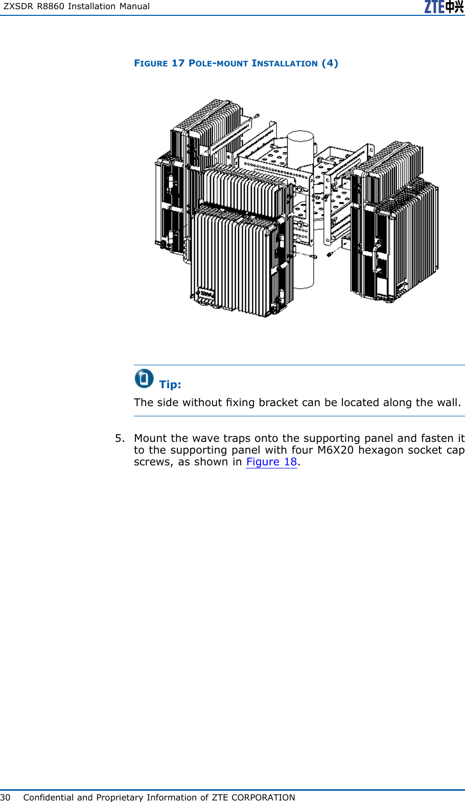
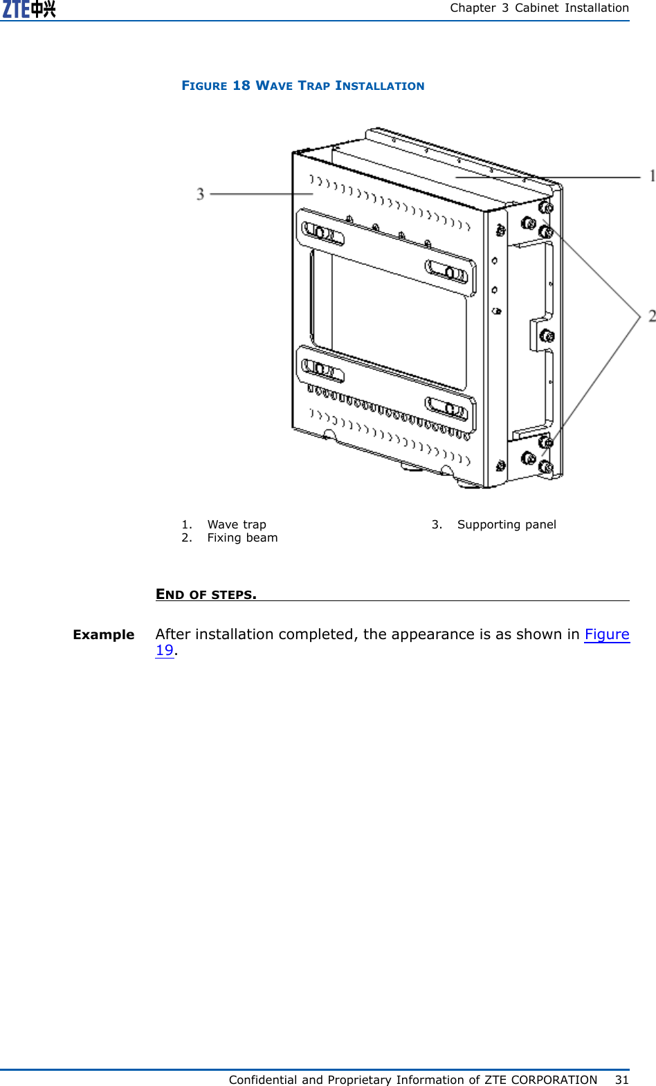
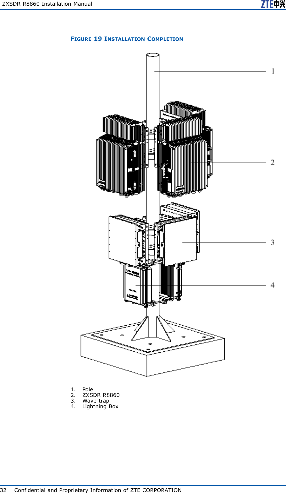
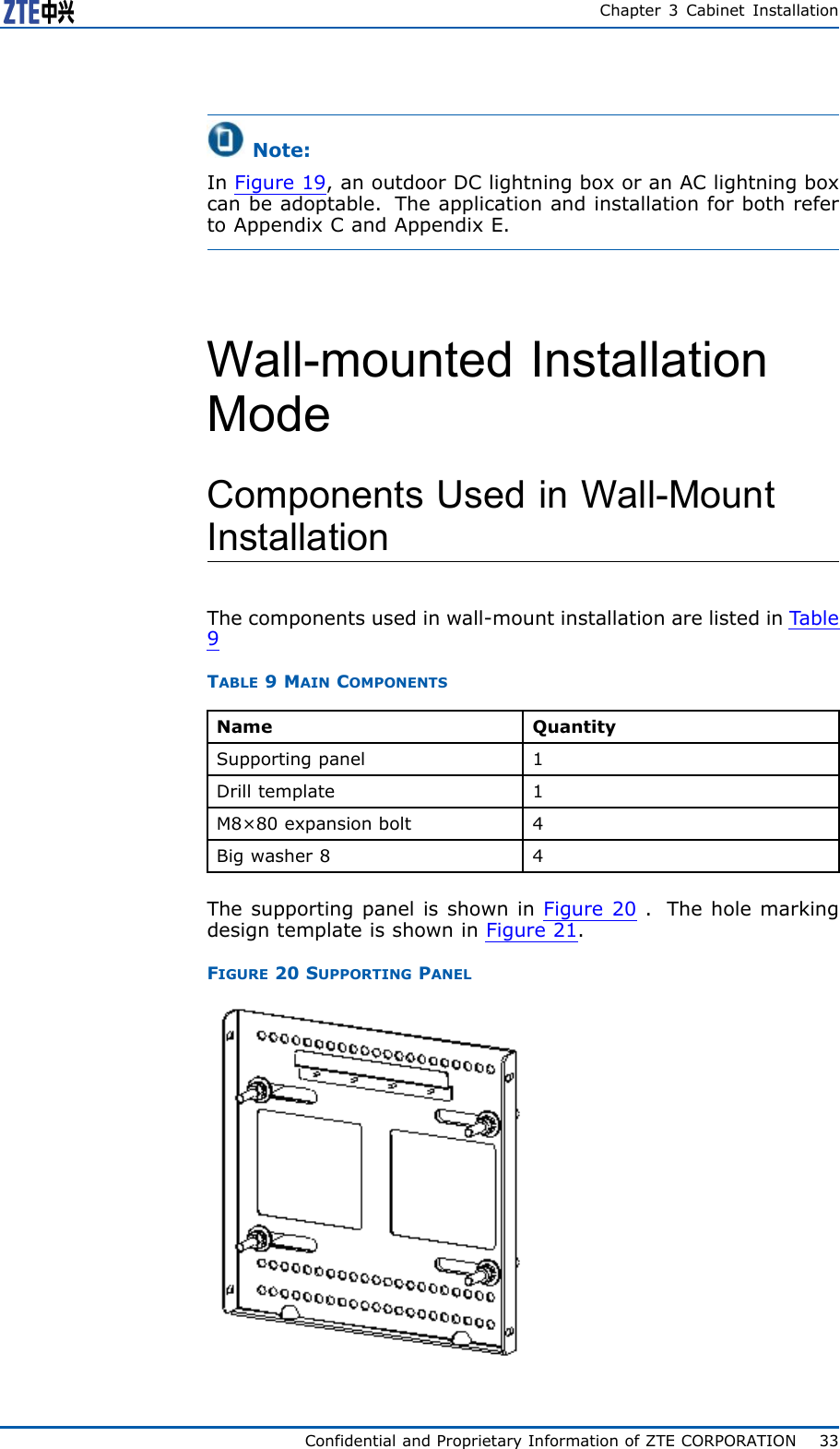
ZTE ZXSDRR8860C206 CDMA Remote Radio Unit User Manual

ZTE Corporation CDMA Remote Radio Unit

User Manual

ZXSDRR8860CDMARemoteRadioUnit-8860InstallationManualZTECORPORATIONZTEPlaza,KejiRoadSouth,Hi-TechIndustrialPark,NanshanDistrict,Shenzhen,P .R.China518057Tel:(86)75526771900Fax:(86)75526770801URL:http://ensupport.zte.com.cnE-mail:support@zte.com.cn
LEGALINFORMATIONCopyright©2006ZTECORPORATION.Thecontentsofthisdocumentareprotectedbycopyrightlawsandinternationaltreaties.Anyreproductionordistributionofthisdocumentoranyportionofthisdocument,inanyformbyanymeans,withoutthepriorwrittenconsentofZTECORPO-RATIONisprohibited.Additionally,thecontentsofthisdocumentareprotectedbycontractualcondentialityobligations.Allcompany,brandandproductnamesaretradeorservicemarks,orregisteredtradeorservicemarks,ofZTECORPORATIONoroftheirrespectiveowners.Thisdocumentisprovided“asis” ,andallexpress,implied,orstatutorywarranties,representationsorconditionsaredis-claimed,includingwithoutlimitationanyimpliedwarrantyofmerchantability,tnessforaparticularpurpose,titleornon-in-fringement.ZTECORPORATIONanditslicensorsshallnotbeliablefordamagesresultingfromtheuseoforrelianceontheinformationcontainedherein.ZTECORPORATIONoritslicensorsmayhavecurrentorpendingintellectualpropertyrightsorapplicationscoveringthesubjectmatterofthisdocument.ExceptasexpresslyprovidedinanywrittenlicensebetweenZTECORPORATIONanditslicensee,theuserofthisdocumentshallnotacquireanylicensetothesubjectmatterherein.ZTECORPORATIONreservestherighttoupgradeormaketechnicalchangetothisproductwithoutfurthernotice.UsersmayvisitZTEtechnicalsupportwebsitehttp://ensupport.zte.com.cntoinquirerelatedinformation.TheultimaterighttointerpretthisproductresidesinZTECORPORATION.RevisionHistoryRevisionNo.RevisionDateRevisionReasonR1.008/30/2008FirstEditionSerialNumber:sjzl20082714
ContentsPreface...............................................................iSafteyDescription.............................................1SafetySpecicationsGuide..............................................1SafetySymbols..............................................................2SafetyInstructions.........................................................3InstallationOverview........................................7ComponentstobeInstalled.............................................7InstallationFlow.............................................................7InstallationPreparation...................................................8EngineeringConditionInspection..................................8ToolsandInstrumentsPreparation................................9On-siteDocuments...................................................10UnpackingAcceptance................................................11CountingGoods................................................11CrateUnpacking...............................................11CartonUnpacking.............................................12AcceptanceandGoodsHandover.........................12CabinetInstallation.........................................15EngineeringIndices.......................................................15InstallationModeInstruction...........................................16Pole-mountedInstallationMode.......................................17ComponentsUsedinPole-mountInstallation.................17InstallingT woZXSDRR8860C806Pole-mountCabinets(WithoutWaveTrap)..........................................19InstallingT woZXSDRR8860C806Pole-mountCabinets(WithWaveTrap)...............................................22InstallingThreeZXSDRR8860C806CabinetsonPole(WithoutWaveTrap)..........................................25InstallingThreeZXSDRR8860C806CabinetonPole(WithWaveTrap)...............................................27Wall-mountedInstallationMode.......................................33
ComponentsUsedinWall-MountInstallation.................33InstallingCabinetonWall(Wall-Mount)........................34FloorGantry-mountedInstallationMode...........................37ComponentsUsedingantry-mountInstallation..............37InstallingCabinetonGantry(WithoutWaveTrap)..........41InstallingCabinetonGantry(WithWaveTrap)...............44SimpliedCabinetIntegratedInstallationMode.................54ComponentsUsedinIntegratedInstallation..................54InstallingIntegratedCabinet.......................................57InstallingSunshield......................................................65ExternalCableInstallation..............................67ExternalCableLayout....................................................67ExternalCableInstallationFlow.......................................69InstallingPowerCable....................................................70InstallingGroundingCable..............................................71InstallingFiberbetweenBBUandRRU..............................72InstallingFiberbetweenRRUandRRU..............................73InstallingEnvironmentMonitoringCable...........................75InstallingAISGControlCable..........................................76InstallingFrequencyPointExtensionCable........................77InstallingJumper...........................................................78MainAntennaFeederSystemInstallation........79MainAntennaFeederSystemStructure............................79MainAntennaFeederSystemInstallationPreparation.........85MainAntennaFeederSystemInstallationFlow..................86AntennaInstallation.......................................................87AntennaInstallationTechnicalSpecications.................87AntennaInstallationPosition.......................................88DirectionalAntennaInstallation...................................88OmniAntennaInstallation..........................................91ConnectJumperandAntenna......................................91FeederInstallation.........................................................92FeederCuttingPrinciple..............................................92FeederInstallationonTopofBuilding...........................93FeederInstallationonTower.......................................94FeederLayoutPrinciples.............................................96FeederFixingProcedures............................................97FeederGroundingPrinciple.........................................97FeederGroundingClipsInstallation..............................99ConnectJumperandFeeder......................................102
InstallingFeederHermetic-window................................102FeederIndoorIngoing..................................................104FeederIndoorArrangementPrinciple..........................104LeadingMainFeederintoRoom................................105InstallingT op-equipmentJumper...............................107PerformingAntennaFeederSystemTest.........................108PerformingOutdoor-connectorWaterproofProcess-ing....................................................................109PerformingFeederHermetic-windowWaterproofProcessing..........................................................111CabinetJumperInstallationDescription..........................114VSWRT est..................................................................115HardwareInstallationInspection..................117CheckingCabinetInstallation........................................117CheckingCableInstallation...........................................117CablesInstallationGeneralSpecication.....................117PowerandGroundingCablesInstallationCheck...........119OpticalFiberInstallationCheck.................................120CheckingMainAntennaSystemInstallation....................120Poweronandoff...........................................123PoweronPreparation...................................................123PowerON...................................................................123PowerOFF..................................................................123Cabinet-combinedInstallation......................125ComponentsUsedinCabinet-combiningInstallation.........125PerformingCabinet-combination....................................127CascadingCabinetInstallation......................129ComponentsUsedinCascadingInstallation.....................129PerformingCabinetCascading.......................................130OAU...............................................................131OAUT echnicalIndices..................................................131OAUAppearanceandInterface......................................132OAUPoleInstallation...................................................134OAUOn-wallInstallation...............................................140OAUCableInstallation.................................................143OLP48-2........................................................149OLP48-2T echnicalIndices............................................149OLP48-2AppearanceandInterface................................149OLP48-2InstallationDescription....................................151
ILP48-3.........................................................157ILP48-3T echnicalIndices.............................................157ILP48-3AppearanceandInterface.................................158ILP48-3InstallationDescription.....................................159ACLightningArrester....................................161ACLightningTechnicalIndices.......................................161ACLightningAppearanceandInterface..........................162ACLightningInstallationDescription..............................163ShieldedGroundingKitInstallation................................168PDM...............................................................173PDMAppearanceandInterface......................................173PDMInstallation..........................................................174Figures..........................................................177Tables...........................................................183ListofGlossary..............................................185
PrefacePurposeZXSDRR8860isanoutdoorremoteRFunit.Composinganinte-gratedBTS,ZXSDRR8860andBBUimplementwirelesstransmis-sionwithincoverageareas,controlofwirelesschannelaswellascommunicationwithBSC.Thismanualprovidesbasicinstallationguideforengineeringper-sonnelwhoperformZXSDRR8860hardwareinstallation.Atthesametime,itservesforthereferencematerialforthepersonnelresponsibleforoperationandmaintenance.IntendedAudienceThisdocumentisintendedforengineersandtechnicianswhoper-forminstallationactivitiesonZXSDRR8841C804remoteradiounit.PrerequisiteSkillandKnowledgeTousethisdocumenteffectively,usersshouldhaveageneralun-derstandingofZXSDRR8860equipmentanditscomponents.Fa-miliaritywiththefollowingishelpful:�cdma2000fundamental�ZXSDRR8860hardwarestructureWhatisinThisManualThismanualcontainsthefollowingchaptersandappendixes:ChapterSummaryChapter1SafetyInstructionDescribesprecautionsinZXSDRR8860installationoroperationmaintenanceaswellasthemeaningsofvarioussafetysymbols.Chapter2InstallationOverviewDescribestherequirementsforZXSDRR8860installationpersonnel,theinstallationowsandinstallationpreparation.Chapter3CabinetInstallationDescribesfourinstallationmodesofZXSDRR8860cabinetandinstallationsituations.Chapter4ExternalCableInstallationDescribestheinstallationmethodsofvariousZXSDRR8860externalcables.Chapter5MainAntennaFeederSystemInstallationDescribestheinstallationowsandinstallationmethodsofZXSDRR8860mainantennafeedersystem.Chapter6HardwareInstallationInspectionDescribestheinspectionmethodsofcabinetandcablesafterinstallationcompletion.ConfidentialandProprietaryInformationofZTECORPORATIONi
ZXSDRR8860InstallationManualChapterSummaryChapter7PoweronandoffDescribesthemethodsandprecautionsofZXSDRR8860poweronandoff.AppendixACabinet-combinedInstallationDescribesthemethodofZXSDRR8860cabinet-combinedinstallation.AppendixBCascadingCabinetInstallationDescribesthemethodofZXSDRR8860cascadingcabinetinstallation.AppendixCOutdoorACUnitOAUDescribestechnicalindices,appearanceinterfaces,installationintroductionandcableconnectionofOAU.AppendixDOutdoorDCLightningBox(OLP48–2)Describestechnicalindices,appearanceinterfaceandinstallationintroductionofoutdoorDClightningbox.AppendixEIndoorDCLightningBox(ILP48–3)Describestechnicalindices,appearanceinterfaceandinstallationintroductionofindoorDClightningbox.AppendixFACLightningBoxDescribesappearanceinterfacesandcableconnectionofAClightningbox.AppendixGPowerDistributionBox(PDM)Describesappearance,interfaceandinstallationintroductionofPDM.iiConfidentialandProprietaryInformationofZTECORPORATION
Chapter1SafteyDescriptionTableofContents:SafetySpecicationsGuide..................................................1SafetySymbols..................................................................2SafetyInstructions.............................................................3SafetySpecificationsGuideThesesafetyinstructionsmustbeconsideredassupplementaryforlocalsafetyregulations.Theprioritymustbegiventolocalsafetyregulationsifthereisanyconictbetweenthetwo.Themaintenancepersonnelmusthavetheknowledgeofsafetyoperationsandmaintenancewithrequiredqualicationandtech-nicalbackground.Warning:Thisdevicecomplieswithpart15oftheFCCRules.Operationissubjecttothefollowingtwoconditions:(1)Thisdevicemaynotcauseharmfulinterference,and(2)thisdevicemustacceptanyinterferencereceived,includinginterferencethatmaycauseunde-siredoperation.Changesormodicationsnotexpresslyapprovedbythepartyresponsibleforcompliancecouldvoidtheuser’sau-thoritytooperatetheequipment.AlltheoperationandmaintenancepersonnelmustfollowthesafetyprecautionsandinstructionsprovidedbyZTECorporationtoavoidanyaccident.Note:ZTECorporationdoesnotbearanyliabilitiesincurredbecauseofviolationoftheuniversalsafetyoperationrequirements,orviola-tionofsafetystandardsfordesigning,manufacturingandusingtheequipment.ConfidentialandProprietaryInformationofZTECORPORATION1
ZXSDRR8860InstallationManualSafetySymbolsTable1listssafetysymbols.TheyaretoprompttheuserofthesafetyprecautionstobeobservedduringZXSDRR8860operationandmaintenance.TABLE1SAFETYSYMBOLSDESCRIPTIONSafetySymbolsMeaningNosmoking:SmokingisforbiddenNoflammables:Noflammablescanbestored.Notouching:Donottouch.Universalalertingsymbol:Generalsafetyattentions.Electricshock:Riskofelectricshock.Electrostatic:Thedevicemaybesensitivetostaticelectricity.Microwave:Bewareofstrongelectromagneticfield.Laser:Bewareofstronglaserbeam.Scald:Bewareofscald.Amongstthesesafetysymbols,theuniversalalarmsymbolsareclassiedintothreelevels:danger ,warning,andcaution.Theformatsandmeaningsofthethreelevelsaredescribedasbelow:Danger:Indicatesapotentiallyhazardoussituationwhich,ifnotavoided,willresultindeathorseriousinjuryofpeople,orequipmentdam-agesandbreakdown.2ConfidentialandProprietaryInformationofZTECORPORATION
Chapter1SafteyDescriptionWarning:Indicatesapotentiallyhazardoussituationwhich,ifnotavoided,couldresultindeathorseriousinjury.Caution:Indicatesapotentiallyhazardoussituationwhich,ifnotavoided,couldresultinseriousinjuries,equipmentdamagesorinterruptionofpartservices.SafetyInstructionsThissectiondescribesthesafetyinstructionsrelatedtoelectricalsafety,antistatic,heavyobjectsandboards.ElectricalSafetyInstructionsThefollowingaretheelectricalsafetyinstructionsabouttools,highvoltage,powercables,holesandlightning:�ToolsUsespecialtoolsratherthancommontoolsforhigh-voltageandACoperations.�HighVoltageDanger:Highvoltageishazardous.Directorindirectcontactwithhighvoltageormainsupplyusingawetobjectcouldresultindeath.�StrictlyfollowlocalsafetyrulestoinstallACpowerequip-ments.�Installationstaffmustbequaliedforperforminghigh-volt-ageandACoperations.�Donotwearanywatch,handchain,bracelet,ringoranyotherconductiveobjectduringsuchoperations.�Preventmoisturefromaccumulatingontheequipmentdur-ingoperationsinadampenvironment.�PowerCableConfidentialandProprietaryInformationofZTECORPORATION3
ZXSDRR8860InstallationManualWarning:Neverinstalloruninstallpowercableswhiletheyarelive.Oth-erwise,thepowercable,whencontactingaconductor ,mayre-sultinsparksorelectricarccausingareorevendamagetoeyes.�Makesuretoshutoffpowersupplybeforeinstallingordis-connectingapowercable.�Beforeconnectingthepowercable,makesurethatthecon-nectingcableanditslabelisappropriatefortheactualin-stallationrequirements.�DrillingHolesWarning:Itisnotallowedtodrillcabinetholeswithoutpermission.�Unqualieddrillingcoulddamagewiringandcablesinsidethecabinet.Additionally,metalpiecesinsidethecabi-netcreatedbythedrillingcouldresultinashortedcircuitboard.Useinsulationprotectionglovesandmovecableswithinthecabinetawayrstwhendrillingisnecessaryonacabinet.�Protecteyesduringdrillingasdustoryingdebrismaydamageeyes.�Cleananydebrisintimeafterdrilling.�LightningDanger:Donotperformhigh-voltage,AC,irontowerormastoperationsinathunderstorm.Thunderstormswouldgiverisetoastrongelectromagneticeldintheatmosphere.Therefore,theequipmentmustbegroundedandprotectedintimeagainstlightningstrikes.AntistaticSafetyInstructionsElectrostatic:Staticelectricityproducedbyhumanbodycandamagestatic-sen-sitivecomponentsoncircuitboard,suchaslarge-scaleintegratedcircuits.�Frictioncausedbyhumanbodyactivitiesistherootcauseofelectrostaticchargeaccumulation.Staticvoltagecarriedbyahumanbodyinadryenvironmentcanbeupto30kV ,andcanremaininthereforalongtime.Anoperatorwithstatic4ConfidentialandProprietaryInformationofZTECORPORATION
Chapter1SafteyDescriptionelectricitymaydischargeelectricitythroughacomponentwhenhe/shetouchestheconductorandcausingdamage.�Wearanantistaticwriststrap(theotherendofwriststrapmustbewellgrounded)beforetouchingtheequipmentorholdingaplug-inboard,circuitboard,IntegratedCircuit(IC)chiporotherdevices,topreventhumanstaticelectricityfromdamag-ingsensitivecomponents.�Aresistorover1MΩshouldbeconnectedinseriesonthecablebetweentheantistaticwriststrapandthegroundingpoint,toprotecttheoperatoragainstaccidentalelectricshock.Resis-tanceover1MΩislowenoughtodischargestaticvoltage.�Theantistaticwriststrapusedmustbesubjecttoregularcheck.Donotreplacethecableofanantistaticwriststrapwithanyothercable.�Donotcontactstatic-sensitiveboardswithanyobjectthateas-ilygeneratesstaticelectricity.Forexample,frictionofpackagebag,transferboxandtransferbeltmadefrominsulationplas-ticmaycausestaticelectricityoncomponents.Dischargeofstaticelectricitymaydamagecomponentswhentheycontactahumanbodyortheground.�Boardshouldonlycontactmaterialssuchasantistaticbag.Keepboardsinantistaticbagsduringstorageandtransporta-tion.�Dischargestaticelectricityofthetestdevicebeforeuse,thatis,groundthetestdevicerst.�DonotplacetheboardnearastrongDCmagneticeld,suchasthecathode-raytubeofamonitor .Keeptheboardatleast10cmaway.HoistingHeavyObjectsWarning:Whenhoistingheavyobjects,ensurethatnobodyisstandingorwalkingunderthehoistedobject.�Ensurethehoistercanmeethoistingrequirementswhendis-assemblingheavyequipment,ormovingandreplacingequip-ment.�Theoperatormustbedulytrainedandqualiedforhoistingoperations.�Hoistingtoolsmustbeinspectedandcompletebeforeservice.�Makesurethathoistingtoolsarexedrmlyonasufcientlysecuredobjectorwallbeforethehoistingoperation.�Givebrieforalinstructionsduringhoistingoperationstopre-ventanymishap.Unplugging/Plug-gingaBoard�Neverplugaboardwithexcessiveforce,toensurethatthepinsonthebackplanedonotgetdeformed.�Plugtheboardrightintotheslotandmakesureboardcircuitfacesdonotcontacteachotherlestanyshortcircuitmayoccur .�Keephandsofftheboardcircuit,components,connectorsandcabletroughwhenholdingaboard.ConfidentialandProprietaryInformationofZTECORPORATION5
ZXSDRR8860InstallationManualOtherSafetyInstructionsNote:Donotperformmaintenanceordebuggingindependently,unlessaqualiedpersonispresent.�Replacinganypartsormakinganychangestotheequipmentmightresultinanunexpecteddanger .Therefore,besurenottoreplaceanypartsorperformanychangestotheequipmentunlessauthorizedotherwise.�ContactZTEofceifyouhaveanyquestion,toensureyoursafety.6ConfidentialandProprietaryInformationofZTECORPORATION
Chapter2InstallationOverviewTableofContents:ComponentstobeInstalled.................................................7InstallationFlow.................................................................7InstallationPreparation.......................................................8ComponentstobeInstalledForZXSDRR8860,thefollowingcomponentswillbeinstalled:�ZXSDRR8860cabinetandcomponentsNote:Theinnercablesandfunctionalmodules/boardsinthecabinetarealreadyinstalledbeforeequipmentdelivery.�Sunshield(usedfortheoutdoorZXSDRR8860installation)�Cables�Antennafeedersystemincludingantenna,jumpersandfeederInstallationFlowTheinstallationowofZXSDRR8860isdemonstratedinFigure1.However ,itisnotrequiredtostrictlyfollowthestepsshowedinthisow.Theactualinstallationproceduresdependontheonsiterequirements.ConfidentialandProprietaryInformationofZTECORPORATION7
ZXSDRR8860InstallationManualFIGURE1INSTALLATIONFLOWInstallationPreparationEngineeringConditionInspectionBeforeinstallingdevices,followtherequirementsofEnvironmentAcceptanceReportandcheckinstallationenvironment.Thefol-lowingcontentisjustasareference.InstallationPositionInspectionZXSDRR8860installationpositionshouldaccordwiththerequire-mentsofengineeringdesign,thespeciedrequirementsasfol-lows:�Avoiddusty,harmful-gasorexplosive-goodsenvironment;�Avoidtheplaceswithbigshockorstrongnoise;�Farawaysubstation;�Farawaypollutionsource;�Avoidanindustrialboilerandheatingboiler;�Farawayhigh-powerwirelessinterferencesource.TemperatureandHumidityInspectionZXSDRR8860temperatureandhumidityinworkenvironmentshouldmeettherequirements,asshownin8ConfidentialandProprietaryInformationofZTECORPORATION
Chapter2InstallationOverviewPowerSupplyInspectionTherequirementsofZXSDRR8860powersupplyaredescribedasfollows.1.DCpowersupply:ZXSDRR8860is–48VDCpowersupplyandthevoltageofpowersupplyis–40VDC~–57VDC.2.IndirectACpowersupply:adoptanoutdoorACunit(OAU);theOAUcanprovide220VACpowersupplyforoneZXSDRB8200C100andoneZXSDRR8860atthesametime.LightningInspectionTheZXSDRR8860lightningrequirementsaredescribedasfollows.�OutdoorInstallationi.ForDCpowersupply,congureanoutdoorDClightningboxOLP48-2.IftheDCpowerisexportedfromtheequipmentroom,thelengthofpowercableismorethan10m(lessthan50m)andtheoutputendofindoorDCpowerisnotconguredwithB-levelorabovelightningdevices,itisre-quiredtocongureanindoorDClightningboxILP48–3intheequipmentroom.ii.ForindirectACpowersupply,itisrequiredtocongureanAClightningbox(ZXPCScombinedarrester).�Forindoorinstallation,ifthepowercableisdistributedout-doors,congurethepowerlightningboxaccordingtothecon-ditionsofoutdoorinstallation.GroundingInspectionZXSDRR8860adoptsanassociatedgroundingmode.Thevalueofgroundingresistanceisnotmorethan5ohm.OtherInspections1.ThecorollarydevicesorcomponentsshouldaccordwiththerequirementsofZXSDRR8860engineeringdesigndrawing.2.ThetransmissiondevicesinterconnectedwithBBUshouldhavebeenprepared.ToolsandInstrumentsPreparationTable2showstoolsandmeterslistrequiredduringinstallation.TABLE2TOOLANDMETERLISTCategoryNameOnefeederconnectorknifeOnewirestripperOnecrimpingpliersSpecial-purposetoolsOnemulti-functionalcrimpingpliersEarthresistancetesterOneelectricpercussiondrillAuxiliaryandsamplebitsOnevacuumcleanerConcretedrillingtoolsPowersocket(two-phaseandthree-phasesocket,withcurrentcapacitygreaterthan15A)ConfidentialandProprietaryInformationofZTECORPORATION9
ZXSDRR8860InstallationManualCategoryNameCrossscrewdrivers(4”,6”and8”each)Flatheadscrewdrivers(4”,6”and8”each)Adjustablewrenches(6’ ,8’,10’and12’)Dual-purposespanners(17”and19”each)Onesetofsocketwrench5kg(11lb)nailhammerOne300WironOne40WironSolderwiresHotblowerOilpaintbrushPliersScissorGeneral-purposetoolsPaperknifeOne50m(164feet)tapemeasureOne5m(16feet)steeltapeOne400mm(16inches)levelbarOneanglemeterOnecompassMeasurementtoolsPlumbAntistaticwriststrapSafetyhelmetProtectiontoolsPairofglovesOnehacksaw(withseveralsawblades)Onepairofsharp-nosepliers(8″)Onepairofdiagonalpliers(8″)Onepairofslipjointpliers(8″)Onepairofvices(8″)ClamptoolsCrowbarChainwheelRopeLadderAuxiliarytoolsForkliftOn-siteDocumentsZXSDRR8860installationneedsthefollowingtechnicaldocumentstobeready.10ConfidentialandProprietaryInformationofZTECORPORATION
Chapter2InstallationOverview�ZXSDRR8860EngineeringExplorationReport�ZXSDRR8860EnvironmentAcceptanceReportZXSDRR8860manualkitincludes:�ZXSDRR8860CommissioningandCongurationManual�ZXSDRR8860OperationandMaintenanceManual�ZXSDRR8860TechnicalManualUnpackingAcceptanceCountingGoodsPrerequisiteThetransportedcargoshouldhavereachedtheinstallationsite.ContextTherepresentativeofcustomerandtheprojectsupervisormustbepresentonsiteduringcountingofgoodsreceived.Ifanypartyisnotpresentatthattime,transportermustholdtheresponsibilityforanydiscrepanciesingoods.Thestepsinvolvedincountinggoodsareasfollows:Steps1.CheckDeliveryChecklistofZTECorporation.Checktotalnum-berofgoods,intactnessofpackingboxes,andcheckwhetherarrivalplaceistheactualinstallationplaceagainstpackinglistnumberattachedtopackingboxes.Ifgoodsareintact,starttounpackandinspectthem.Note:Itisrecommendedtounpackthegoodsafterabout30minutesofreceivingthecargo,sincethereisapossibilityofmoisturecontentduetotemperaturevariationsifany.2.Equipmentinspectionlistandunpackingacceptancereportarepresentintherstpackingcarton.Firstly,openrstpackingcartonandtakeouttheUnpackingAcceptanceReporttocheckwhetherthegoodsreceivedareinaccordancewiththeinspec-tionlist.3.Duringthecountingandunpackinginspectionprocess,ifanymaterialisfoundshort,orgoodsdamaged,thenll-inUnpack-ingAcceptanceFeedbackTableandcontactZTEpromptly.ENDOFSTEPS.CrateUnpackingPrerequisitePreparetheappropriatetoolssuchasstraightscrewdriver ,pliers,andcrowbar .ContextPerformthefollowingstepstoopenthecrate:ConfidentialandProprietaryInformationofZTECORPORATION11
ZXSDRR8860InstallationManualSteps1.Insertastraightscrewdriverintotheslitbetweencrateandfrontcoverboardtomakeitloose;theninsertcrowbartoun-clenchcoverboard.2.Pullthecoverboardoutfromthecrate.3.Removetheotherboardsofthecrate.ENDOFSTEPS.CartonUnpackingPrerequisitePreparetheappropriatetoolssuchasstraightscrewdriver ,diago-nalpliers,andpaperknife.ContextPerformthefollowingstepstounpackthecarton:Steps1.Usediagonalplierstocutpackingstraps.2.Useapaperknifetocutadhesivetapealongtheslitsoncartoncover ,avoiddamaginggoodsinside.3.Openthecarton,andremovethefoamboard.4.Checkthegoodswithinthecarton.Note:�Avoiddamagingtheantistaticbag(Itcanbeusedinthefutureforstorageofspareparts)duringunpacking.�Whiletheequipmentismovedtoahotteranddamperplace,waitfor30minutesbeforeunpackingtheequipment.Otherwise,moisturemaycondenseonthesurfaceoftheequipmentandcausedamage.�Properlydisposeofrecycledesiccants.ENDOFSTEPS.AcceptanceandGoodsHandoverContextPerformthisprocedureforacceptinggoods,andhandingthemovertooperators.Steps1.AcceptanceBaseduponthename,categoryandnumbermentionedontheshippinglist,carefullycheckthegoodspiecebypiece.Makesurethatgoodsfullthefollowingconditions:i.Makesurethattherearenobubbly,peeling,nickandlthmarkonthesurfaceofthechassis.ii.Ensurethatoilpaintonthechassissurfaceisintact.iii.Ensureclampingscrewsaretightandintact.iv.Allthecomponentsareproperlyinstalledattheirrespectivepositions.12ConfidentialandProprietaryInformationofZTECORPORATION
Chapter2InstallationOverviewv.Laydowntheinspectedgoodsaccordingtocategories.2.HandoverAftercompletingtheunpackingprocedure,representativeofcustomerandprojectsupervisorshouldapproveandsignUn-packingforInspectionReport.EachpartyshouldhaveacopyofUnpackingforInspectionReport.Ifthegoodsarestillun-derthesupervisionoftheoperatorevenafteracceptance,thengoodswillnotbehandedovertotheoperatoruntilbothpartiessignonthereport.ENDOFSTEPS.ConfidentialandProprietaryInformationofZTECORPORATION13
ZXSDRR8860InstallationManualThispageisintentionallyblank.14ConfidentialandProprietaryInformationofZTECORPORATION
Chapter3CabinetInstallationTableofContents:EngineeringIndices...........................................................15InstallationModeInstruction...............................................16Pole-mountedInstallationMode...........................................17Wall-mountedInstallationMode...........................................33FloorGantry-mountedInstallationMode...............................37SimpliedCabinetIntegratedInstallationMode.....................54InstallingSunshield..........................................................65EngineeringIndicesTable3describestheengineeringindicesofZXSDRR8860.TABLE3ZXSDRR8860ENGINEERINGINDICESItemIndicesOverallDimensionWidthxHeightxDepth:320mmx500mmx172mmUpperEnclosureDimensionWidthxHeightxDepth:320mmx370mmx72mmLowerEnclosureDimensionWidthxHeightxDepth:320mmx500mmx100mmWeight<22kgPower-48VDC;-40V~-57V220VAC:150V~285V/45Hz~65Hz(viaexternalAC-to-DCconversionlightningbox)WorkTemperature-40℃to55℃-40℉to131℉WorkHumidity5%RH~95%RHPowerConsumptionofNormalWorkUnder-48VDCPowerSupply�1Carrier–OutputPower:20W/C/S–PowerConsumption:170W�2Carrier–OutputPower:20W/C/S–PowerConsumption:200W�3Carrier–OutputPower:20W/C/S–PowerConsumption:230WConfidentialandProprietaryInformationofZTECORPORATION15
ZXSDRR8860InstallationManualThetechnicalindicesoftheindoorDClightningbox,exempliedbyJD40K085C20H2–K1Z,arelistedinTable4,whichissubjecttotheactualeldtechnicalspecicationsforpracticalapplication.TABLE4JD40K085C20H2–K1ZDCLIGHTNINGBOXTECHNICALINDICESItemIndexDimensionsWidthxHeightxDepth:400mmx450mmx100mm(Theheightoftopcoverboxlockexcluded)NominalWorkingVoltage–48VInstallationModeIndoorwall-mountinstallationWorkingTemperature-5℃to70℃WorkingHumidity≤95%RHThetechnicalindicesoftheexternalAC-to-DCconversionlightningbox,exempliedbyGPAD501M54-1A,arelistedinT able5,whichissubjecttotheactualeldtechnicalspecicationsforpracticalapplication.TABLE5GPAD501M54-1AEXTERNALAC-TO-DCCONVERSIONLIGHTNINGBOXTECHNICALINDICESItemIndexDimensionsWidthxHeightxDepth:217mmx288mmx127mmWeight4.65kgInputVoltageMin.value:150VTypicalvalue:220VMax.value:285VInputFrequencyMin.value:45HzTypicalvalue:50HzMax.value:65HzInstallationModePole-mountandwall-mountinstallationWorkingTemperature-40℃+65℃WorkingHumidity5%95%InstallationModeInstructionAccordingtodifferentinstallationenvironments,therearethreemodesofZXSDRR8860installation:�Pole-mountinstallation�Wall-mountinstallation�Gantry-mountinstallation�Simplied-cabinetintegrativeInstallation16ConfidentialandProprietaryInformationofZTECORPORATION
Chapter3CabinetInstallationPole-mountedInstallationModeComponentsUsedinPole-mountInstallationThemaincomponentsusedinpole-mountinstallationinclude:�Poleanchorclampcomponents;�Polexingbracketcomponents.Thepoleanchorclampcomponentsareusedforpole-mountin-stallationofoneortwoZXSDRR8860s.Thepolexingbracketcomponentsareusedforpole-mountinstallationofthreeZXSDRR8860s.Themainpoleanchorclampcomponentsusedinpole-mountin-stallationforsingleZXSDRR8860arelistedinTable6TABLE6MAINCOMPONENTLIST1NameQuantityShortanchorclamp2Longanchorclamp2Standardspringwasher104M10×120hexagonheadbolt(fullthread)4I-typecommonM10hexagonalnut4Flatwasher104Standardspringwasher84M8×40hexagonheadbolt4Bigwasher84Themainpoleanchorclampcomponentsusedinpole-mountin-stallationfortwoZXSDRR8860arelistedinTable7TABLE7MAINCOMPONENTLIST2NameQuantityLonganchorclamp4Standardspringwasher104M10×120hexagonheadbolt(fullthread)4M10×80hexagonheadbolt(fullthread)4ConfidentialandProprietaryInformationofZTECORPORATION17
ZXSDRR8860InstallationManualNameQuantityI-typecommonM10hexagonalnut4Flatwasher104Standardspringwasher88M8×40Hexagonheadbolt8Bigwasher88Themainpolexingbracketcomponentsusedinpole-mountin-stallationforthreeZXSDRR8860arelistedinTable8TABLE8MAINCOMPONENTLIST3NameQuantityPolefixingbracket4Standardspringwasher104M10×120hexagonheadbolt(fullthread)4I-typecommonM10hexagonalnut4Flatwasher104Standardspringwasher812M8×40hexagonheadbolt12Bigwasher812Figure2illustratespoleanchorclampcomponents.Figure3illus-tratespolexingbracketcomponents.FIGURE2POLEANCHORCLAMPCOMPONENTS18ConfidentialandProprietaryInformationofZTECORPORATION
Chapter3CabinetInstallationFIGURE3POLEFIXINGBRACKETCOMPONENTSNote:ThepoleanchorclampcomponentsshowninFigure2isadoptedinonepole-mountinstallation.Thepoleanchorclampcomponentsusedintwopole-mountinstallationonlychangestwoshortanchorclampsintotwolonganchorclamps,thespeciclistdescribedinTable7InstallingTwoZXSDRR8860C806Pole-mountCabinets(WithoutWaveTrap)Steps1.Fixanchorclampsbacktobackontothepole,andaligntheholesandscrewdownabitwithbolts.Adjustspacebetweenanchorclampsbasedonthescrews’positionofsupportingpanelasshowninFigure4.ConfidentialandProprietaryInformationofZTECORPORATION19
ZXSDRR8860InstallationManualFIGURE4POLE-MOUNTINSTALLATION(1)1.I-typecommonM10hexago-nalnut2.Standardspringwasher103.Bigatwasher104.Longanchorclamp5.M10×120hexagonheadbolt(fullthread)Tip:DuringtwoZXSDRR8860cabinetinstallation,thesuggestedpolediameteris60to120mmandtherearetwokindsofboltlengths:�Usetheboltoflength80mmforpolediameterof60mmto90mm;�Usetheboltoflength120mmforpolediameterof90mmto120mm.2.FixtwosupportingpanelsontheanchorclampwithM8boltsandscrewM10boltstightly,asshowninFigure5.20ConfidentialandProprietaryInformationofZTECORPORATION
Chapter3CabinetInstallationFIGURE5POLE-MOUNTINSTALLATION(2)1.M8×40Hexagonheadbolt2.Standardspringwasher83.Bigatwasher84.Insulationange5.Supportingpanel6.Insulationboard7.Longanchorclamp3.MountthetwoZXSDRR8860cabinetsonthesupportingpanelandfastenthecabinetwithfourM6X20hexagonsocketcapscrewsasshowninFigure6.FIGURE6POLE-MOUNTINSTALLATION(3)ConfidentialandProprietaryInformationofZTECORPORATION21
ZXSDRR8860InstallationManualENDOFSTEPS.InstallingTwoZXSDRR8860C806Pole-mountCabinets(WithWaveTrap)ContextWhileinstallingtheZXSDRR8860C806pole-mountinstallationwithtwowavetraps,adoptanchorclamps;forthepole-mountinstallationofthreewavetraps,adoptxingbrackets.Steps1.Fixanchorclampsbacktobackontothepole,aligntheholesandscrewdownabitwithbolts.AdjustspacebetweenanchorclampsasshowninFigure7.FIGURE7POLE-MOUNTINSTALLATION(1)1.I-typecommonM10hexago-nalnut2.Standardspringwasher103.Flatwasher104.Longanchorclamp5.M10×120hexagonheadbolt(fullthread)22ConfidentialandProprietaryInformationofZTECORPORATION
Chapter3CabinetInstallationTip:DuringtwoZXSDRR8860installation,thesuggestedpoledi-ameteris60to120mmandtherearetwokindsofboltlengths:�Usetheboltoflength80mmforpolediameterof60mmto90mm.�Usetheboltoflength120mmforpolediameterof90mmto120mm.2.FixtwosupportingpanelsontheanchorclampswithM8boltsandscrewdownM10bolts,asshowninFigure8.FIGURE8POLE-MOUNTINSTALLATION(2)1.M8×40hexagonheadbolt2.Standardspringwasher83.Bigatwasher84.Insulationange5.Supportingpanel6.Insulationboard7.Longanchorclamp3.RepeattheStep1~Step2toinstalltwoanchorclampsandtwosupportingpanels.4.MountthetwoZXSDRR8860cabinetsontothesupportingpan-elsandfastenthecabinetwithfourM6X20hexagonsocketcapscrewsasshowninFigure9.ConfidentialandProprietaryInformationofZTECORPORATION23
ZXSDRR8860InstallationManualFIGURE9POLE-MOUNTINSTALLATION(3)5.Mountthetwowavetrapsontothesupportingpanelsandfas-tenthemtothesupportingpanelswithfourM6X20hexagonsocketcapscrewsasshowninFigure10.FIGURE10WAVETRAPINSTALLATION1.Wavetrap2.Fixingbeam3.Supportingpanel24ConfidentialandProprietaryInformationofZTECORPORATION
Chapter3CabinetInstallationENDOFSTEPS.InstallingThreeZXSDRR8860C806CabinetsonPole(WithoutWaveTrap)Steps1.Fixthetwosetsofxingbracketsontothepoleandaligntheholesandscrewitabitwithbolts,asshowninFigure11FIGURE11POLE-MOUNTINSTALLATION(1)1.FixingBracket2.M10×120hexagonheadbolt(fullthread)3.Standardspringwasher104.Flatwasher105.I-typecommonM10hexago-nalnut2.Adjustspacebetweenthexingbracketsbasedonthescrews’positionofinsulationboardsatthebackofsupportingpanelsasshowninFigure12.FixthreesupportingpanelsonthexingbracketswithM8bolts.ScrewthexingbracketswithM10bolts.ConfidentialandProprietaryInformationofZTECORPORATION25
ZXSDRR8860InstallationManualFIGURE12POLE-MOUNTINSTALLATION(2)1.Fixingbracket2.Insulationboard3.Supportingpanel4.Insulationange5.Bigatwasher86.Standardspringwasher87.M8×40Hexagonheadbolt3.MounttheZXSDRR8860cabinetsonthesupportingpanelsandfastenthecabinetswithM6X20hexagonsocketcapscrewsasshowninFigure13.FIGURE13POLE-MOUNTINSTALLATION(3)26ConfidentialandProprietaryInformationofZTECORPORATION
Chapter3CabinetInstallationTip:Thesidewithoutxingbracketcanbelocatedalongthewall.ENDOFSTEPS.InstallingThreeZXSDRR8860C806CabinetonPole(WithWaveTrap)ContextWhileinstallingtheZXSDRR8860C806pole-mountinstallationwithtwowavetraps,adoptanchorclamps;forthepole-mountinstallationofthreewavetraps,adoptxingbrackets.Steps1.Fixthetwosetsofxingbracketsontothepoleandaligntheholesandscrewitabitwithbolts,asshowninFigure14.FIGURE14POLE-MOUNTINSTALLATION(1)1.FixingBracket2.M10×120hexagonheadbolt(fullthread)3.Standardspringwasher104.Flatwasher105.I-typecommonM10hexago-nalnut2.Adjustspacebetweenthexingbracketsbasedonthescrews’positionofinsulationboardsatthebackofsupportingpanelsasshowninFigure15.FixthreesupportingpanelsonthexingbracketswithM8bolts.ScrewdownthexingbracketswithM10bolts.ConfidentialandProprietaryInformationofZTECORPORATION27
ZXSDRR8860InstallationManualFIGURE15POLE-MOUNTINSTALLATION(2)1.Fixingbracket2.Insulationboard3.Supportingpanel4.Insulationange5.Bigatwasher86.Standardspringwasher87.M8×40Hexagonheadbolt3.RepeattheStep1~Step2toinstalltwosetsofxingbracketsandthreesetsofsupportingpanels,asshowninFigure16.28ConfidentialandProprietaryInformationofZTECORPORATION
Chapter3CabinetInstallationFIGURE16POLE-MOUNTINSTALLATION(3)1.Supportingpanel4.MounttheZXSDRR8860cabinetsonthesupportingpanelsandfastenthecabinetswithM6X20hexagonsocketcapscrewsasshowninFigure17.ConfidentialandProprietaryInformationofZTECORPORATION29
ZXSDRR8860InstallationManualFIGURE17POLE-MOUNTINSTALLATION(4)Tip:Thesidewithoutxingbracketcanbelocatedalongthewall.5.MountthewavetrapsontothesupportingpanelandfastenittothesupportingpanelwithfourM6X20hexagonsocketcapscrews,asshowninFigure18.30ConfidentialandProprietaryInformationofZTECORPORATION
Chapter3CabinetInstallationFIGURE18WAVETRAPINSTALLATION1.Wavetrap2.Fixingbeam3.SupportingpanelENDOFSTEPS.ExampleAfterinstallationcompleted,theappearanceisasshowninFigure19.ConfidentialandProprietaryInformationofZTECORPORATION31
ZXSDRR8860InstallationManualFIGURE19INSTALLATIONCOMPLETION1.Pole2.ZXSDRR88603.Wavetrap4.LightningBox32ConfidentialandProprietaryInformationofZTECORPORATION
Chapter3CabinetInstallationNote:InFigure19,anoutdoorDClightningboxoranAClightningboxcanbeadoptable.TheapplicationandinstallationforbothrefertoAppendixCandAppendixE.Wall-mountedInstallationModeComponentsUsedinWall-MountInstallationThecomponentsusedinwall-mountinstallationarelistedinT able9TABLE9MAINCOMPONENTSNameQuantitySupportingpanel1Drilltemplate1M8×80expansionbolt4Bigwasher84ThesupportingpanelisshowninFigure20.TheholemarkingdesigntemplateisshowninFigure21.FIGURE20SUPPORTINGPANELConfidentialandProprietaryInformationofZTECORPORATION33
ZXSDRR8860InstallationManualNote:Thesupportingpanel,asthecommoncomponentinZXSDRR8860installation,isusedinthewall-mount,pole-mountandgantry-mountinstallationmodes.FIGURE21HOLEMARKINGDESIGNTEMPLATE(UNIT:MM)InstallingCabinetonWall(Wall-Mount)ContextFigure22illustratesthespacerequirement(Unit:mm)forwall-mountinstallation.34ConfidentialandProprietaryInformationofZTECORPORATION
Chapter3CabinetInstallationFIGURE22SPACEREQUIREMENTFORWALL-MOUNTINSTALLATION(UNIT:MM)Steps1.Firstlymarktheholepositionsonthewallwithholedesigntemplate.Drillthemarkedpointsabout60mmwithpercussivedrillandinstalltheexpansionbolts.2.FixthesupportingpanelonthewallwithboltsasshowninFigure23ConfidentialandProprietaryInformationofZTECORPORATION35
ZXSDRR8860InstallationManualFIGURE23SUPPORTINGPANELINSTALLATIONONWALL1.M8×80expansionbolt2.Insulationboard3.Supportingpanel4.Insulationange5.Bigatwasher86.Standardspringmat87.M8nutl3.MounttheZXSDRR8860cabinetontothesupportingpanel,andfastenthecabinetwithfourM6X20hexagonsocketcapscrewsasshowninFigure24.36ConfidentialandProprietaryInformationofZTECORPORATION
Chapter3CabinetInstallationFIGURE24MOUNTINGCABINET1.Supportingpanel2.M6safeguardscrew3.RetainingboardENDOFSTEPS.FloorGantry-mountedInstallationModeComponentsUsedingantry-mountInstallationThecomponentsusedingantry-mountinstallationincludesagantryandsupportingpanels.ThequantityofsupportingpanelsisconsistentwiththatofZXSDRR8860s.ForeveryZXSDRR8860cabinet,onesupportingpanelisrequired.ConfidentialandProprietaryInformationofZTECORPORATION37
ZXSDRR8860InstallationManualTable10listssomecomponentsofgantry.TABLE10MAINCOMPONENTSNameQuantityGantry1M5X16screw24M10X40tappingscrew6M10X100expansionbolt4Figure25showstheappearanceofgantry.38ConfidentialandProprietaryInformationofZTECORPORATION
Chapter3CabinetInstallationFIGURE25GANTRYAPPEARANCE1.Coverplate2.Uprightcolumn3.Tiltedsupport4.M5X16screw5.Baseplate6.M10X40tappingscrew7.M10X100expansionboltConfidentialandProprietaryInformationofZTECORPORATION39
ZXSDRR8860InstallationManualNote:AdopttheM10X100expansionboltwhileinstallingthegantryonaconcretebaseplate;adopttheM10X40tappingscrewwhilein-stallingthegantryinsideabunker .Table11listssomecomponentsofsupportingpanel.TABLE11MAINCOMPONENTSNameQuantitySupportingpanel1M8×80expansionbolt4Bigwasher84Figure26showstheappearanceofsupportingpanel.FIGURE26SUPPORTINGPANEL40ConfidentialandProprietaryInformationofZTECORPORATION
Chapter3CabinetInstallationNote:Thesupportingpanel,asthecommoncomponentinZXSDRR8860installation,isusedinthewall-mount,pole-mountandgantry-mountinstallationmodes.InstallingCabinetonGantry(WithoutWaveTrap)Steps1.Assemblethegantryi.FixtheuprightcolumnuponthebaseplatewiththeM5X16screws,asshowninFigure27.FIGURE27FIXUPRIGHTCOLUMNANDBASEPLATE1.M5X16screwii.FastenthejunctionbetweenuprightcolumnandcoverplatewiththeM5X16screws,asshowninFigure28.ConfidentialandProprietaryInformationofZTECORPORATION41
ZXSDRR8860InstallationManualFIGURE28FASTENUPRIGHTCOLUMNANDCOVERPLATE1.M5X16screwiii.FastenthetiltedsupportwiththeM5X16screws,asshowninFigure29FIGURE29FASTENTILTEDSUPPORT1.M5X16screw2.InstallthegantryAccordingtothespeciedinstallationpositionintheengineer-ingdesigndrawing,drillthemarkedholesandinstalltheex-pansionbolts.42ConfidentialandProprietaryInformationofZTECORPORATION
Chapter3CabinetInstallationNote:AdopttheM10X100expansionboltwhileinstallingthegantryonaconcretebaseplate;adopttheM10X40tappingscrewwhileinstallingthegantryinsideabunker .3.InstalltheZXSDRR8860i.Fastenthesupportingpanelsontotheproperpositionsofgantrywithbolts.ii.MounttheZXSDRR8860cabinetsontothesupportingpanels,andfastenthecabinetswithfourM6X20hexagonsocketcapscrews.ENDOFSTEPS.ExampleTheappearanceafterinstallationcompletionisasshowninFigure30.ConfidentialandProprietaryInformationofZTECORPORATION43
ZXSDRR8860InstallationManualFIGURE30ZXSDRR8860INDOORGANTRY-MOUNTINSTALLATIONAPPEARANCE(ONLYRRUINSTALLED)InstallingCabinetonGantry(WithWaveTrap)Steps1.Assemblethegantry.44ConfidentialandProprietaryInformationofZTECORPORATION
Chapter3CabinetInstallationi.FixtheuprightcolumnuponthebaseplatewiththeM5X16screws,asshowninFigure31.FIGURE31FIXUPRIGHTCOLUMNANDBASEPLATE1.M5X16screwii.FastenthejunctionbetweenuprightcolumnandcoverplatewiththeM5X16screws,asshowninFigure32.FIGURE32FASTENUPRIGHTCOLUMNANDCOVERPLATE1.M5X16screwConfidentialandProprietaryInformationofZTECORPORATION45
ZXSDRR8860InstallationManualiii.FastenthetiltedsupportwiththeM5X16screws,asshowninFigure33.FIGURE33FASTENTILTEDSUPPORT1.M5X16screw2.Installthegantry.Accordingtothespeciedinstallationpositionintheengineer-ingdesigndrawing,drillthemarkedholesandinstalltheex-pansionbolts.Note:AdopttheM10X100expansionboltwhileinstallingthegantryonaconcretebaseplate;adopttheM10X40tappingscrewwhileinstallingthegantryinsideabunker .3.Installthesupportingbracketofwavetrap.ThesupportingbracketofwavetrapisasshowninFigure34.FastenthesupportingbracketontothegantrywithM8bolts,asshowninFigure35.46ConfidentialandProprietaryInformationofZTECORPORATION
Chapter3CabinetInstallationFIGURE34SUPPORTINGBRACKET1.M8bolt2.Insulationboard3.Supportingbracket4.InstalltheZXSDRR8860.i.Fastenthesupportingpanelsontotheproperpositionsofgantrywithbolts,asshowninFigure35.ConfidentialandProprietaryInformationofZTECORPORATION47
ZXSDRR8860InstallationManualFIGURE35SUPPORTINGBRACKETANDWALL-MOUNTASSEMBLIES1.Gantry2.Supportingbracket3.Supportingpanel4.BBUwall-mountframeii.MounttheZXSDRR8860cabinetsontothesupportingpanels,andfastenthecabinetswithfourM6X20hexagonsocketcapscrews,asshowninFigure36.48ConfidentialandProprietaryInformationofZTECORPORATION
Chapter3CabinetInstallationFIGURE36ZXSDRR8860INSTALLATION5.Installthewavetrap.TheappearanceofwavetrapisasshowninFigure37.InsertthewavetrapintothesupportingbracketandfastenthemwithM6bolts,asshowninFigure38.ConfidentialandProprietaryInformationofZTECORPORATION49
ZXSDRR8860InstallationManualFIGURE37WAVETRAP1.Guideblock2.Wavetrap3.M6bolt4.Frontbafer50ConfidentialandProprietaryInformationofZTECORPORATION
Chapter3CabinetInstallationFIGURE38WAVETRAPINSTALLATIONENDOFSTEPS.ExampleTheZXSDRR8860gantry-mountintegratedinstallationiscom-pleted.TheprolesareasshowninFigure39andFigure40.ConfidentialandProprietaryInformationofZTECORPORATION51
ZXSDRR8860InstallationManualFIGURE39GANTRY-MOUNTINTEGRATEDINSTALLATION1.ZXSDRR88602.ZXSDRB8200C1003.Groundingcopperbar4.Gantry5.Wavetrap52ConfidentialandProprietaryInformationofZTECORPORATION
Chapter3CabinetInstallationFIGURE40GANTRY-MOUNTINTEGRATEDINSTALLATION(SIDE)ConfidentialandProprietaryInformationofZTECORPORATION53
ZXSDRR8860InstallationManualSimplifiedCabinetIntegratedInstallationModeComponentsUsedinIntegratedInstallationTheZXSDRR8860forintegratedinstallationneedsthefollowingcomponents:asimpliedcabinet,anupperxingframeandalowerxingframe.Thedimensionofsimpliedcabinetis1650×600×450(H×W×D;unit:mm),asshowninFigure41.54ConfidentialandProprietaryInformationofZTECORPORATION
Chapter3CabinetInstallationFIGURE41SIMPLIFIEDCABINETAPPEARANCE1.M10×100expansionboltTheupperxingframeisasshowninFigure42.ConfidentialandProprietaryInformationofZTECORPORATION55
ZXSDRR8860InstallationManualFIGURE42UPPERFIXINGFRAME1.Upperxingframe2.Supportingpanel3.M6×16pan—headscrew4.M4×12pan—headscrewTheupperxingframeisasshowninFigure43.56ConfidentialandProprietaryInformationofZTECORPORATION
Chapter3CabinetInstallationFIGURE43LOWERFIXINGFRAME1.M6×16pan—headscrew2.Supportingpanel13.M4×12pan—headscrew4.Lowerxingframe5.M6×16pan—headscrew6.Supportingpanel2InstallingIntegratedCabinetPrerequisiteUnpackingandacceptancefortheZXSDRR8860andthesimpliedcabinetmeetrequirements.Steps1.Installthesimpliedcabinet.Accordingtoaninstallationpositionintheengineeringdesigndocument,drillholesontheindooroor .Theholepositionsandthedimensionareasshownin.FastenthecabinetontheoorwithM10×100expansionbolts.ConfidentialandProprietaryInformationofZTECORPORATION57
ZXSDRR8860InstallationManualFIGURE44HOLEPOSITIONSANDDIMENSION2.InstalltheZXSDRR8860.showsallassembliesforZXSDRR8860integrated-cabinetin-stallation.58ConfidentialandProprietaryInformationofZTECORPORATION
Chapter3CabinetInstallationFIGURE45ZXSDRR8860ASSEMBLIES1.Upperxingframe2.Lowerxingframe3.ZXSDRR8860i.RemovethexingbeamsofZXSDRR8860.TheZXSDRR8860carriestwoxingbeamsusedforwall-mountandpole-mountinstallations,asshownin.Removethexingbeams.ConfidentialandProprietaryInformationofZTECORPORATION59
ZXSDRR8860InstallationManualFIGURE46ZXSDRR8860FIXINGBEAM1.Fixingbeamii.Installthelowerxingframe.InserttheZXSDRR8860tothelowerxingframe.Fastenthesupportingpanel2withtheZXSDRR8860byM6×12pan-headscrewsandfastenthesupporting1withZXSDRR8860byM6×16pan-headscrews,asshownin.60ConfidentialandProprietaryInformationofZTECORPORATION
Chapter3CabinetInstallationFIGURE47LOWERFIXINGFRAMEINSTALLATION1.Pan-headscrewM6×162.an-headscrewM6×12iii.Installtheupperxingframe.InserttheZXSDRR8860tothelowerxingframe.FastenthesupportingpanelofupperxingframewiththeZXSDRR8860byM6×16pan-headscrews,asshownin.ConfidentialandProprietaryInformationofZTECORPORATION61
ZXSDRR8860InstallationManualFIGURE48ZXSDRR8860INSTALLEDWITHUPPERANDLOWERFIXINGFRAME1.M6×16pan-headscrew3.InstalltheZXSDRR8860tothesimpliedcabinet.AligntheguidancechannelontheZXSDRR8860installedwiththeupperandlowerxingframestotherailonethesimpliedcabinet.ThenslidetheZXSDRR8860slowlyintothesimpliedcabinetandfastenthemwithfourM6×16pan-headscrews,asshownin.62ConfidentialandProprietaryInformationofZTECORPORATION
Chapter3CabinetInstallationFIGURE49ZXSDRR8860INSTALLATIONTOSIMPLIFIEDCABINET1.M6×16pan-headscrew4.InstallotherZXSDRR8860s.RepeattheStep2~Step4toinstallotherZXSDRR8860sintothesimpliedcabinet.WhensixZXSDRR8860sareinstalledcompletely,theappearanceisasshownin.ConfidentialandProprietaryInformationofZTECORPORATION63
ZXSDRR8860InstallationManualFIGURE50ZXSDRR8860INSTALLATIONCOMPLETIONENDOFSTEPS.64ConfidentialandProprietaryInformationofZTECORPORATION
Chapter3CabinetInstallationInstallingSunshieldContextThecomponentsusedforinstallingsunshademustbeprepared.showsthesunshadetobeinstalled.FIGURE51SUNSHIELDSTRUCTURE1.Sunshield2.M5screw3.Fixingposition(wedgedontotheboltatthesideofthecommonpartforwallmounting)4.M6screw5.ZXSDRR8860cabinetSteps1.Assemblethesunshadeonsiteandxthebrackettotheshield.ConfidentialandProprietaryInformationofZTECORPORATION65
ZXSDRR8860InstallationManual2.UnscrewthetwoM6screwatthesidetopofthecabinetandinserttheboltsatbothsidesofthewall-mountingcommonparttothesunshade.3.ScrewthetwoM6screwsandfourM5screwsonbothsidesofthecabinetandtightenthem.ENDOFSTEPS.66ConfidentialandProprietaryInformationofZTECORPORATION
Chapter4ExternalCableInstallationTableofContents:ExternalCableLayout........................................................67ExternalCableInstallationFlow...........................................69InstallingPowerCable........................................................70InstallingGroundingCable..................................................71InstallingFiberbetweenBBUandRRU..................................72InstallingFiberbetweenRRUandRRU..................................73InstallingEnvironmentMonitoringCable...............................75InstallingAISGControlCable..............................................76InstallingFrequencyPointExtensionCable............................77InstallingJumper...............................................................78ExternalCableLayoutTheconnectionrelationshipofZXSDRR8860externalcablesisdescribedinT able12.TABLE12ZXSDRR8860EXTERNALCABLECONNECTIONRELATIONSHIPNameConnectionRelationshipDescriptionPowercableConnectstheZXSDRR8860powerinterface(DCIN)tothepowersupplyequipmentinterfaceOneendistheaviationplugandtheotherendisreservedforpowercablemadeonsite.Thelengthofcableisbasedontheengineeringsurvey.ConfidentialandProprietaryInformationofZTECORPORATION67
ZXSDRR8860InstallationManualNameConnectionRelationshipDescriptionGroundingcableConnectsoneZXSDRR8860groundbolttothecopperbarThegroundingcableismadeupofstrandsofflame-retardantwire.ThecrosssectionalareaofZXSDRR8860groundingcableis10mm2.Thecolorofgroundingcableisyellowandgreen.CopperlugsarecrimpedatbothendsoftheZXSDRR8860groundingcable.OpticalFiberTherearetwotypesofZXSDRR8860fiber:BBUconnection/ZXSDRR8860cascading.TherearetwotypesofZXSDRR8860opticalfiber:oneusedinBBUconnectionandtheotherusedincascadingbetweenZXSDRR8860s.EnvironmentmonitoringcableConnectstheZXSDRR8860environmentmonitoringinterfaceMONtotheexternalmonitoringcomponentsorthedrycontact.AendoftheenvironmentmonitoringcableisPINdesign.Bend,with3mlengthintotal,needsmakingbasedontheon-siteengineering.AISGcontrolcableConnectstheZXSDRR8860debugginginterface(AISG)tothecontrolinterfaceofelectrical-adjustmentantenna.AISGisusedforcontroloftheelectrical-adjustmentantenna.FrequencypointextensioncableInterconnectstheZXSDRR8860RXin/RXoutinterfaces.Thefrequencypointextensioncableusuallyadoptsthefinished1/2″jumperwith2mlength.Thejumpercanbeself-madebasedonthereal-timeconditiononsite.AandBendsofjumperareNconnectors(male).Antenna,feederandjumperConnectstheZXSDRR8860tothemainfeeder.TheRFjumperusuallyadoptsthefinished1/2″jumperwith2mlength.Thejumpercanbeself-madebasedonthereal-timeconditiononsite.TheendofjumperisNconnector(male)andtheotherendisDINconnector(female).68ConfidentialandProprietaryInformationofZTECORPORATION
Chapter4ExternalCableInstallationExternalCableInstallationFlowFigure52liststheinstallationowofexternalcable.Thisowcanbeadjustedbasedonthereal-timecondition.FIGURE52EXTERNALCABLEINSTALLATIONFLOWConfidentialandProprietaryInformationofZTECORPORATION69
ZXSDRR8860InstallationManualInstallingPowerCableContextTheZXSDRR8860cabinetadopts-48VDCforpowersupply.EndAistheaviationplugandEndBisreservedforself-madepowercableonsite.Thelengthofpowercableisaccordingtotheengi-neeringsurvey.ZXSDRR8860Figure53showsthestructureofpowercable.FIGURE53POWERCABLESTRUCTURETable13describesthecolorsandspecicationsofinsidecoreca-ble.TABLE13COLORANDSPECIFICATIONColorSpecificationBlue-48VBlack-48VGNDNote:1.Ifthetwo-corecableisadopted,thebluecorecablestandsfor-48Vandtheblackcorecablestandsfor-48VGND;2.Ifthefour-corecableisadopted,thetwobluecorecablesconnectedinparallelstandfor-48Vandtheblackcorecablesconnectedinparallelstandfor-48VGND.Steps1.ConnectEndAofpowercablewithDCINinterfacelocatedatthebottomofZXSDRR8860.2.StriptheprotectivecoatofEndBandconnectitwiththeDCinputpowersourceaccordingtocolorsoftheinsidecorecable.3.MakewaterproofprotectionofEndB.4.Attachlabelsatbothendsofthepowercable.5.Fixthepowercable.ENDOFSTEPS.70ConfidentialandProprietaryInformationofZTECORPORATION
Chapter4ExternalCableInstallationInstallingGroundingCableContextThegroundingcableismadeupofstrandsofame-retardantwire.ThecrosssectionalareaofZXSDRR8860groundingcableis10mm2.Thecolorofgroundingcableisyellowandgreen.CopperlugsarecrimpedatbothendsoftheZXSDRR8860groundingca-ble,asshowninFigure54.FIGURE54GROUNDINGCABLESTRUCTURESteps1.CoverandxacopperlugontheagroundingboltoftheZXSDRR8860cabinet,asshowninFigure55.FIGURE55ZXSDRR8860GROUNDINGBOLT1.GroundingboltConfidentialandProprietaryInformationofZTECORPORATION71
ZXSDRR8860InstallationManual2.Connecttheothercopperlugtotheearth-networkingcopperbarandxitwithabolt,asshowninFigure56.FIGURE56EARTH-NETWORKCOPPERBAR(UNIT:MM)3.Attachthelabelonthegroundingcable.4.Measurethegroundingresistanceandmakesureitlessthan5Ω.ENDOFSTEPS.InstallingFiberbetweenBBUandRRUPrerequisiteTheZXSDRR8860cabinetmustbeinstalledandxedsuccessfully.ContextFigure57showsberconnectionbetweenZXSDRR8860andBBU.FIGURE57FIBERCONNECTIONBETWEENZXSDRR8860ANDBBU1.OutdoorSealComponentWhileconnectingaBBUtoZXSDRR8860,makesurethatthebase-bandRFberinterface(LC1/2)oftheZXSDRR8860isconnectedtotheopticalinterfaceconnectoroftheBBU.72ConfidentialandProprietaryInformationofZTECORPORATION
Chapter4ExternalCableInstallationSteps1.Attachlabelsatbothendsoftheber .2.AdjustthesideofEndAwiththecolormarkandinserttheZXSDRR8860berinterface,andscrewdownthenuts,asshowninFigure58FIGURE58OPTICALFIBERINSTALLATION1.Colormark3.ConnectEndAofthebertothebasebandRFberinterface(LC1/2)oftheZXSDRR8860.4.ConnectEndBoftheber ,whichisaDLCconnector ,totheBBUopticalconnector .5.ScrewdowntheoutdoorsealcomponentatEndAforwater-proong.ENDOFSTEPS.InstallingFiberbetweenRRUandRRUPrerequisiteThecascadingZXSDRR8860cabinetsmustbeinstalledandxedsuccessfully.ContextFigure59showsberconnectionbetweenZXSDRR8860s.ConfidentialandProprietaryInformationofZTECORPORATION73
ZXSDRR8860InstallationManualFIGURE59FIBERCONNECTIONBETWEENZXSDRR8860S1.OutdoorSealComponentWhileinterconnectingtheZXSDRR8860s,makesurethatthetwobasebandRFberinterfaces(LC1/2)oftheZXSDRR8860arecon-nected.Steps1.Attachlabelsatbothendsoftheopticalber .2.AdjustthesideofEndAwiththecolormarkandinserttheZXSDRR8860berinterface,andscrewdownthenuts,asshowninFigure60.FIGURE60OPTICALFIBERINSTALLATION1.Colormark3.ConnectEndAoftheopticalbertothebasebandRFberinterface(LC1/2)oftheZXSDRR8860.4.ConnectEndBoftheopticalbertotheotherbasebandRFberinterface(LC1/2)oftheZXSDRR8860.74ConfidentialandProprietaryInformationofZTECORPORATION
Chapter4ExternalCableInstallation5.ScrewdowntheoutdoorsealcomponentatEndAforwater-proong.ENDOFSTEPS.InstallingEnvironmentMonitoringCablePrerequisiteTheZXSDRR8860cabinetmustbeinstalledandxedsuccessfully.ContextTheenvironmentmonitoringcableprovidesa485interface,usedforZXSDRR8860environmentmonitoring.Inaddition,theca-blealsoprovidesfourextensionaccessesforexternaldrycontactmonitoring.EndAisthe37PINconnector ,andEndBismadebyon-siteengi-neering.Thetotallengthis3m.Figure61showstheappearanceofenvironmentmonitoringcable.FIGURE61ENVIRONMENTMONITORINGCABLETheconnector ,connectingtheenvironmentmonitoringcabletotheZXSDRR8860,adopts37–coreaviationjack.TheconnectoraccordswiththeGJB599specication.TheconnectorappearanceisasshowninFigure62FIGURE62AVIATIONJACKAPPEARANCETable14describestheconnectorpins.ConfidentialandProprietaryInformationofZTECORPORATION75
ZXSDRR8860InstallationManualTABLE14CABLEPINDESCRIPTIONPinCore-CableColorSignalDescription15/16Whiteandblue/blueDrycontact4-/+17/18Whiteandorange/orangeDrycontact3-/+19/20Whiteandgreen/greenDrycontact2-/+21/22Whiteandbrown/brownDrycontact1-/+23/24Redandblue/blueRS485receive25/26Redandorange/orangeRS485transmitSteps1.ConnectEndAtotheMONinterfacelocatedatthebottomofZXSDRR8860.2.ConnectEndBwithexternalmonitoringdevicesordrycon-tacts.3.AttachthelabelatEndB.ENDOFSTEPS.InstallingAISGControlCableContextTheAISGcontrolcableisusedforcontroloftheelectricaladjust-mentantenna.Figure63showsthestructureoftheAISGcontrolcable.FIGURE63AISGCONTROLCABLESTRUCTURETable15describestheserialNo.meaningofAISGcontrolcable.76ConfidentialandProprietaryInformationofZTECORPORATION
Chapter4ExternalCableInstallationTABLE15AISGCONTROLCABLEDESCRIPTIONSerialNo.NameMeaning1TRX_ANT_485_+RS485+2TRX_ANT_485_-RS485-3,4TRX_ANT_28V28V5,6TRX_ANT_28VGND28VGND7,8NCNullSteps1.ConnectEndAtotheZXSDRR8860debugginginterface(AISG)andscrewdownthebolt;2.ConnectEndBtothecontrolinterfaceofelectricaladjustmentantennaandscrewdownthebolt.ENDOFSTEPS.InstallingFrequencyPointExtensionCablePrerequisiteThetwoZXSDRR8860cabinetstobecombinedmustbeinstalledandxedsuccessfully.ContextAfterthecombinationofcabinets,theZXSDRR8860cansupport8carriersectorsatmost.ThetwoZXSDRR8860cabinetsareconnectedthroughtheircon-nectinginterfacessuchasRXinandRXoutbytwofrequencypointextensioncables.Figure64showsthestructureofthefrequencypointcable.EndAandEndBareNconnectors(male).The2M1/2″jumperisoftenusedforthefrequencypointextensioncable.Itmaybepreparedonsiteifnecessary.FIGURE64FREQUENCYPOINTEXTENSIONCABLESteps1.ConnectEndAofthefrequencypointextensioncabletothefrequencypointextensioninterfaceRXINofoneZXSDRR8860;2.ConnectEndBtoRXoutoftheotherZXSDRR8860;ConfidentialandProprietaryInformationofZTECORPORATION77
ZXSDRR8860InstallationManual3.ConnecttheremainingRXin/RXoutinterfacesofthetwocom-binedcabinetswiththeotherfrequencypointextensioncable.ENDOFSTEPS.InstallingJumperContextOneendofRFjumperconnectswiththemainfeederandtheotherendconnectswiththeantennafeederinterfaceofZXSDRR8860cabinet.BeforeinstallingtheRFjumper ,themainfeederisin-stalled.TheRFjumperadoptsthe1/2″jumperwitha2mlength.Thejumpercanalsobeself-madeaccordingtotheon-sitecondition.TheinstallationpositionofRFjumperisasshowninFigure65.FIGURE65RFJUMPERINSTALLATIONPerformthefollowingstepstoinstalltheRFjumper .Steps1.ConnecttheDINconnector(male)ofRFjumperwiththeDINconnector(female)ofmainfeeder .2.ConnecttheDINconnector(male)ofRFjumperwiththeDINconnector(female)ofZXSDRR8860cabinet.3.SealtheconnectorswithwaterproofadhesivetapesandPVCtapes.ENDOFSTEPS.78ConfidentialandProprietaryInformationofZTECORPORATION
Chapter5MainAntennaFeederSystemInstallationTableofContents:MainAntennaFeederSystemStructure................................79MainAntennaFeederSystemInstallationPreparation.............85MainAntennaFeederSystemInstallationFlow......................86AntennaInstallation...........................................................87FeederInstallation.............................................................92InstallingFeederHermetic-window....................................102FeederIndoorIngoing......................................................104PerformingAntennaFeederSystemTest.............................108PerformingOutdoor-connectorWaterproofProcessing...........109PerformingFeederHermetic-windowWaterproofProcess-ing................................................................................111CabinetJumperInstallationDescription..............................114VSWRT est......................................................................115MainAntennaFeederSystemStructureThetypicalcongurationsforZXSDRR8860mainantennafeedersystemdescribedbelowincludes:�ZXSDRR8860congurationwithcommonantenna�ZXSDRR8860congurationwithcommonantenna,AISGdualpoweramplier�ZXSDRR8860congurationwithelectronicadjustmentan-tenna(1)�ZXSDRR8860congurationwithelectronicadjustmentan-tenna(2)�ZXSDRR8860congurationwithelectronicadjustmentan-tenna,AISGdualpoweramplierZXSDRR8860congurationwithcommonantennaInthisconguration,generallyZXSDRR8860installationpositionisnearantennaandtheyareallinstalledonthebuildingtop.ZXSDRR8860isconnectedtotheantennaby1/2″feederdirectly,occasionally5/4″or7/8″feederisadopted,asshowninFigure66.ConfidentialandProprietaryInformationofZTECORPORATION79
ZXSDRR8860InstallationManualFIGURE66ZXSDRR8860CONFIGUREDWITHCOMMONANTENNA.ZXSDRR8860congurationwithcommonantenna,Inthisconguration,generallyZXSDRR8860isinstalledonthetower .ZXSDRR8860isconnectedtotheantennaby5/4″or7/8″feeder ,asshowninFigure67.80ConfidentialandProprietaryInformationofZTECORPORATION
Chapter5MainAntennaFeederSystemInstallationAISGdualpoweramplierFIGURE67ZXSDRR8860CONFIGURATIONWITHCOMMONANTENNA,AISGDUALPOWERAMPLIFIERConfidentialandProprietaryInformationofZTECORPORATION81
ZXSDRR8860InstallationManualZXSDRR8860congurationwithelectronicadjustmentantenna(1)Inthisconguration,generallyZXSDRR8860installedneartheantennaonthebuildingtop.ZXSDRR8860isconnectedtotheantennaby1/2″feederdirectly,occasionally5/4″or7/8″feederisadopted,asshowninFigure68.FIGURE68ZXSDRR8860CONFIGURATIONWITHELECTRONICADJUSTMENTANTENNA(1)ZXSDRR8860congurationwithelectronicInthisconguration,generallyZXSDRR8860isinstallednearthetopofthetower .ZXSDRR8860isconnectedtotheantennaby5/4″or7/8″feederisadopted,asshowninFigure69.82ConfidentialandProprietaryInformationofZTECORPORATION
Chapter5MainAntennaFeederSystemInstallationadjustmentantenna(2)FIGURE69ZXSDRR8860CONFIGURATIONWITHELECTRONICADJUSTMENTANTENNA(2)ConfidentialandProprietaryInformationofZTECORPORATION83
ZXSDRR8860InstallationManualZXSDRR8860congurationwithelectronicadjustmentantenna,AISGdualpoweramplierInthisconguration,generallyZXSDRR8860isinstallednearthetopofthetower .ZXSDRR8860isconnectedtotheantennaby5/4″or7/8″feederisadopted,asshowninFigure70.FIGURE70ZXSDRR8860CONFIGURATIONWITHELECTRONICADJUSTMENTANTENNA.AISGDUALPOWERAMPLIFIER84ConfidentialandProprietaryInformationofZTECORPORATION
Chapter5MainAntennaFeederSystemInstallationMainAntennaFeederSystemInstallationPreparationProperantennainstallationisveryimportanttoZXSDRR8860sys-temreliableoperation.Beforeinstallation,makesurethatinstalla-tionstaffisqualiedandthefollowingrequirementsaresatised.PersonnelRequirementNormally,supervisorsareinchargeofdirectionandsupervision,whereasinstallationpersonnelcarryouttheinstallation.�InstallationSupervisorTherequirementsfortheinstallationsupervisorareasfollows:�Familiarwithallmaterials,toolsandoperationmethods.�Theyareinchargeofassigningdifferentworktotheproperemployeewhoisgoodattheoperation,especiallywhileworkingontheirontower .Note:Safetyisthemostimportantconsiderationwhenassigningwork.�InstallationPersonnelTherequirementsfortheinstallationpersonnelareasfollows:�Installationemployeesarerequiredtoinstallantennasys-temskillfullyunderthedirectionofsupervisor .�Employeesontowermustbequaliedandingoodphysicalstate.�Installationafterdrinkingisforbidden.EnvironmentRequirementPayattentiontofollowingitemsandcheckwhethertheysatisfyrequirementsinengineeringdesign.Normally,theyarecompletedbythenetworkoperator(carrier).�LightningprotectionandgroundingZXSDRR8860isusuallylocatedoutdoors.Thegroundingstakeandoutdoorlightning-protectinggroundingcablesareinstalledbytheoperator ,andthesupervisorshouldconrmlightning-protectinggroundingcablesareinstalledproperly.�PoleandsupportingrackAccomplishinstallationofantennasupportingrackandpoleaccordingtoprojectdesignrequirement.Thestabilityofthesupportingrackandpoleshouldbeinaccordancewiththede-signrequirement.�FeederlayoutFieldengineersneedtodeterminerouteofmainfeederwithoperatorengineersbeforeinstallation.ConfidentialandProprietaryInformationofZTECORPORATION85
ZXSDRR8860InstallationManual�Electronicpowerenvironment�ZXSDRR8860antennaandfeedersystemcannotbeinstalledtooneartopublicelectricpowercables.SafetyPrecautionsEnsurethefollowingprecautionsbeforeantennainstallation:�Takenecessarymeasuresforpersonalandequipmentsafety.�Personnelundertowermustwearsafetyhelmets.�Personnelontowermustwearsafetybelt.�Neverclimbtowerwithlooseclothesandwet/slipperyshoes.�Duringactiveantennaadjustment,wearradiation-shieldingclothingandturnoffpowerampliertoavoidradiationeffects.�Ifpossible,installinsunnyandwindlessdays.Installationisforbiddeninrain,strongwind,thunderandlightning.�Makecautionbrandinengineeringeldandkeeppassengersawayfromengineeringeld,especiallykids.�Whenworkingontower ,putunusedtoolsinatoolbagandpreventthemfromdroppingdownfromtowertohurtpeople.ToolsRequire-mentThefollowingtoolsarerequiredformainantennafeedersysteminstallation:�MeasuretoolsCompass,multimeter ,anglemeter ,andtapemeasure�SpecialtoolsMainfeederconnectormanufacturing,specialtoolsandinstru-mentsfortest�RegulartoolsAdjustablewrench,sharp-nosepliers,diagonalpliers,hacksaw(withseveralsawblades)�ProtectiontoolsSafetyhelmet,safetybelt,safetyrope,gloves,radia-tion-shieldingclothes,multiplepowersocketandsealedcanvastoolbag�OthertoolsToolsforlifting,e.g.LadderMainAntennaFeederSystemInstallationFlowFigure71showstheinstallationowofmainantennafeedersys-tem.86ConfidentialandProprietaryInformationofZTECORPORATION
Chapter5MainAntennaFeederSystemInstallationFIGURE71MAINANTENNAFEEDERSYSTEMINSTALLATIONFLOWAntennaInstallationAntennaInstallationTechnicalSpecificationsTheantennatechnicalspecicationsandtheirdescriptionisgivenbelow.�AntennaheightTheinstallationheightofantennaisdeterminedbynetworkplanningdesign.�AntennaazimuthTheazimuthoftheantennaisdeterminedbynetworkplanningdesign.�AntennadowntiltThedowntiltangleoftheantennaisdeterminedbynetworkplanningdesign.Usuallythedowntiltangleis0°~10°�AntennadirectionConfidentialandProprietaryInformationofZTECORPORATION87
ZXSDRR8860InstallationManualAntennadirectiondependsontheantennaazimuth.Iftwoantennasinonesector ,mustsharethesameazimuth.AntennaInstallationPositionTheantennainstallationpositionmustbeinaccordancewithprojectdesign.Iftheinstallationpositionneedsanymodication,theprojectsupervisormustnegotiatewithoperator’srepresen-tative.TheantennainstallationpositionneedstotakecareforelightningprotectionasshowninFigure72.FIGURE72ANTENNAINSTALLATIONPOSITION1.Lightningrod2.45°Lightningprotectionarea3.Antenna4.GroundingcableFollowingarelightningprotectionrequirementstoinstallanan-tenna:�Theantennashouldbeinstalledwithin45°coverageareaoflightningrod.�Ifthereisnospeciallightningprotectionarrangementliketheabove,installthelightningprotectionsystemontotheantennapole.�Makesurethatthelightningrodiswellgrounded.DirectionalAntennaInstallationContextThedirectionalantennainstallationprocedureisgivenbelow.88ConfidentialandProprietaryInformationofZTECORPORATION
Chapter5MainAntennaFeederSystemInstallationNote:Thefollowingstepsdescribetheinstallationprocessasareferenceforinstallationpersonnel.Duringtheon-siteinstallationprocess,pleasecarefullyreadtheinstallationmanualprovidedwiththean-tenna,andcarryouttheinstallationaccordingtotheactualcon-dition.Performthefollowingstepstoinstalladirectionalantenna:Steps1.Firstlyassemblefastener"C"ontotheupperandlowerendsofantennaasshowinFigure73,thenconnectfasteners"B"and"A"tocompletetheinitialinstallationofthedirectionalantenna.Note:�Allaccessoriesmustbeinstalledwithspringandplainwashers.�Usuallytheantennafasteningaccessoriesandtheangleadjustmentdeviceaccessorieshavealreadybeeninstalledontheantennabeforexingintothetower .FIGURE73DIRECTIONALANTENNAINSTALLATIONConfidentialandProprietaryInformationofZTECORPORATION89
ZXSDRR8860InstallationManual2.Attachtheantennaalongwithxturesontothepole.Donottightenthescrewstootightlytoalloweasyadjustmentofthedirectionanddowntiltoftheantenna.However ,degreeoftightnessmustbehighenoughtoensurethattheantennadoesnotsliddownward.3.Adjusttheantenna’sazimuth.i.Determinetheazimuthoftheantennabyusingacompass,anddeterminetheinstallationdirectionaccordingtotheengineeringdesigndrawing.ii.Turntheantennaslightlytoadjustit’sfacedirectionasshowninFigure73.Atthesametime,measurethedirec-tionoftheantennawithacompassuntiltheerrorcomeswithintheengineeringdesignrequirements(generallynotmorethan5°).iii.Afteradjustingtheazimuthoftheantenna,tightenthefas-tener"A".4.Adjusttheantenna’sdowntilti.Adjustthedowntiltofthemeasurementmetertoobtaintherequiredangleaccordingtotheengineeringdesign.ii.Turnthetopoftheantennaslightly,andlooseorfasttheantennaatitstop.Adjustthedowntiltangleoftheantennatillthemeasurementmeter’sbubblecomestobecenteredasshowninFigure74.FIGURE74ANTENNADOWNTILTADJUSTMENTiii.Afteradjustingthedowntiltoftheantenna,tightenthefas-tener"B.ENDOFSTEPS.ResultThedirectionalantennaisinstalled.90ConfidentialandProprietaryInformationofZTECORPORATION
Chapter5MainAntennaFeederSystemInstallationOmniAntennaInstallationContextPerformfollowingstepstoinstallanOmnidirectionalantenna:Steps1.Determinetheinstallationposition.2.Sealtheantenna’slowerpart(jumper)withthejacketandplacetheantennaasmuchclosetothesupportingpole.3.Ensurethatthetopofthejacketslightlyhigherthanthetopofsupportingpole.4.FastentheantennaontothesupportingpolewithtwoxingclipsasshowninFigure75.Donotfastentheclipswhethertootightlyorloosely.Iffastenedtootightly,thejacketmaybedamaged;iffastentooloosely,theweight-bearingandwind-resistancerequirementscannotbemet.FIGURE75OMNIDIRECTIONALANTENNAINSTALLATION1.Antenna2.Fixingclips3.Antennapole5.Measuretheverticalityoftheantenna,andensurethatan-tennaisvertical.6.Afterensuringtheverticalitytightenthexingclipsrmly.7.Aftertheantennaisinstalledontothesupport,xtheantennasupportontothetower .ENDOFSTEPS.ResultTheOmnidirectionalantennaisinstalled.ConnectJumperandAntennaContextPerformthefollowingstepstoconnectjumperwithantenna.ConfidentialandProprietaryInformationofZTECORPORATION91
ZXSDRR8860InstallationManualNote:Theantennajumpercanbeconnectedbeforetheantennamountedontothepole,andneededtotakethewaterproofmeasurements.Thishighlyreducestheworktime,providegoodconnection,andimproveswaterpreventionquality.Steps1.Connectthejumperconnectortotheantennaport,andtightenitproperly.2.Sealthejumperconnectorandantennaportforwaterprooftreatment.i.Wrapthewaterproofadhesivetapeslowersideofconnec-tors.Keepwrappingdirectionsameastheonethatthejumperistightened.ii.Whilewrapping,extendtheadhesivetapestodoubletheirlength.NotethateverywrappinglayermustbeoverlappedthepreviouslayerbyhalfthewidthofthetapeWrap-pingmustbeextendedupto50mm(2inches)awayfromjumperconnectorposition.iii.Gripthetapewithyourhandstomakethetapetightlyadhered.iv.WrapPVCtapesontopofthewaterproofadhesivetape.Duringtheprocess,makesuretheupperlayeroverlapsthelowerlayerbyhalfthewidthofthetape.ENDOFSTEPS.ResultThejumperisconnectedwithantenna.FeederInstallationFeederCuttingPrincipleDeterminelengthofthefeederaccordingtonalfeederroute,andcutthefeedersaccordingtothelengthrequiredofeachfeeder .Note:Ifthefeederlengthislessthan10meters,use1/2”feeder;ifthefeederlengthis10~30meters,use7/8”feederandifthefeederlengthismorethan30meters,use5/4”feeder .Followingarethetypicalfeedercuttingscenarioobservedon-site:�Iftheantennafeedersystemistobeinstalledonthebuildingroof92ConfidentialandProprietaryInformationofZTECORPORATION
Chapter5MainAntennaFeederSystemInstallation1.Measurethelengthofmainfeederforeachsectoraccordingtothenalfeederroute.2.Addanappropriatemargin(1m(3.3feet)~2m(6.6feet))tothemeasuredlengthswhencuttingthefeeders.3.Aftercuttingonemainfeeder ,attachthetemporarylabelsatbothendsofthefeeder ,suchasANT0andANT2.Attachtheformallabelstothefeederafteritisinstalled.4.Carrythecutfeederstotheroofofthebuilding,andmakesuretheyarenotsqueezedordamagedduringtheprocess.�Iftheantennafeedersystemistobeinstalledonanirontower1.Hoistoneendofthefeedertothetopofthetowerbyusingapulleyblockandpullingrope.Beforehoisting,maketheuppermainfeederconnector .2.Thepersonnelonthetowermustcutthefeederaccordingtothedistancefromthepointwherethefeederenterstheroomtothelightningarresterrack,withanappropriatemarginre-served.Makeatemporarylabelforthelowerpart.Attachtheformallabelstothefeederafteritisinstalled.Caution:Attheendoffeedercuttingprocess,attachlabelatbothends.Temporarylabelscanalsobeattachedtothemiddleofthefeederduringthefeedercuttingprocess.Makesurethatalllabelsareconsistentwiththeactualsituation.Otherwise,thefeedermaynotbeconnectedcorrectlyandthesectorsmaynotcorrespondtothefeeder .FeederInstallationonTopofBuildingPrerequisiteThesupportingpoleandantennaisinstalled.ContextPerformthefollowingstepstoinstallthemainfeederontopofbuilding:Steps1.Firstlydeterminethenalmainfeederroute.2.Cutthemainfeederaccordingtothedeterminedlengthonthenalroute.3.Arrangethemainfeederingoodorderwithoutcrossing.4.Preparetheconnectorsandjumpers.5.Laythefeedersaccordingtothelayingprinciple.6.LaythemainfeederalongtothesupportingpoleasshowninFigure76.ConfidentialandProprietaryInformationofZTECORPORATION93
ZXSDRR8860InstallationManualFIGURE76FEEDERFIXING1.Antenna2.Feeder3.SupportingclipsNote:�Makesurethatthefeederlaidistightened.�Thebendingradiusofthefeederisnolessthan20timesofmainfeederradius.Theradiusofsinglebendisnolessthan90mm(3.54inches),andtherepeatedbendradiusisminimum200mm(7.9inches).7.Connectfeederwiththeantenna.ENDOFSTEPS.ResultThefeederissuccessfullyinstalledonthetopofbuilding.FeederInstallationonTowerPrerequisiteEnsurethatthelabelsareattachedatabout0.3m(1feet)awayfrommainfeederatbothends,andarecorrect.94ConfidentialandProprietaryInformationofZTECORPORATION
Chapter5MainAntennaFeederSystemInstallationContextCaution:�Hoistthemainfeederwithcaretoavoiddamagingit’ssheath.Ifanypartofsheathisdamaged,thenitmaycausetheentirefeedertobediscarded.�Takecareforpersonnelsafetywhenhoistingthefeeders.Thefeederinstallationinvolvesthefollowingssteps:Steps1.Wrapthemainfeederconnectorwithapieceofaxorananti-staticplasticbaglledwithfoam,andthenbindittightlywithcableties.2.Knotandxthecutfeedercablewithhoistingropeattwopoints.Oneis0.4m(1.5/16feet)awayfromthefeedercon-nectorandtheotheroneis3.4m(11.2/16feet)away.Warning:Avoidfeederandit’sconnectorfromcollidingwiththeirontower .3.Afterhoistingmainfeedercablestothetowertop,xupperendofcableatmultiplepointstopreventitfromslippingdownthetower .ThefeederhoistingisshowninFigure77ConfidentialandProprietaryInformationofZTECORPORATION95
ZXSDRR8860InstallationManualFIGURE77HOISTINGFEEDERTOTOWER1.Pulleyblock2.Feederheadwrap3.Feederlabel4.Knotpositionintheupwardrope5.DownwardropeENDOFSTEPS.ResultThefeederishoistedonthetowersuccessfully.FeederLayoutPrinciplesThefeedershouldbelaidinaccordancewiththefollowingprinci-ples:�Themainfeedermustbelaidingoodorderandwithoutcross-ings.�Thefeederroutemustbedeterminedbeforeconnectingthemainfeeder .Marktheactualfeederrouteonadrawingtoavoidreworksduetocrossings.�Theminimumbendingradiusofthemainfeedershouldbegreaterthan20timesofthemainfeederradius.Thebendingradiusofasinglebendshouldbegreaterthan90mm(3.54inches).Theminimumbendingradiusofrepeatedbendsis200mm(8inches).�Ifmorethanonetriplefeederclipsareusedinfeederrouting,thenmaximumdistancebetweentriplefeederclipsshouldbenotmorethan1.65m(5.41feet).96ConfidentialandProprietaryInformationofZTECORPORATION
Chapter5MainAntennaFeederSystemInstallationFeederFixingProceduresContextPerformthefollowingstepstoxthemainfeeder:Steps1.Firstlyarrangethemainfeederinagoodorder .2.Fastenmainfeedersfromtopdownwardwiththetriplefeederclipsafterarrangingthemainfeeders.Figure78showstheappearanceoftriplefeederclip.FIGURE78TRIPLEFEEDERCLIPAPPEARANCENote:Donotfastenfeedersatbothendssimultaneously.3.Keepmainfeedersstraightandinagoodorderwithoutanybulgesbetweenthetriplefeederclips.4.Tightenthetriplefeederclipsrmly.ENDOFSTEPS.ResultThefeederxingiscompleted.FeederGroundingPrincipleThegroundingprinciplesofmainfeederisasfollows:�Toinstallmainantennafeedersystemontower ,mainfeedermustbeinstalledwithfeedergroundingclipsatleastinthreeplaces:�Towerplatform�Theplacewherethemainfeederleavesthetower�TheplacebeforewherethemainfeederisconnectedtothechassisConfidentialandProprietaryInformationofZTECORPORATION97
ZXSDRR8860InstallationManualWhenthemainfeederisover60m(197feet)inlength,feedergroundingclipsmustbeaddedinthemiddle.Generally,agroundingclipmustbeinstalledonthefeederevery20m(65.6feet),asshowninFigure79.FIGURE79FEEDERGROUNDINGSCHEMATICDIAGRAM1.Towerplatform2.Feedergroundingclip3.Feeder4.Cabinetjumper5.Groundingcable6.Groundingbusbar7.Groundgrid�Toinstallthemainantennafeedersystemontheroof,itsan-tennasupportandcablerackmustbeweldedtothelight-ningprotectiongridofthebuilding.Themainfeedermustbegroundedatthreeplaces:98ConfidentialandProprietaryInformationofZTECORPORATION
Chapter5MainAntennaFeederSystemInstallation�Theplacewherefeederleavesthepole�Theplacewherefeederleavestheroof�Theplacebeforewherethemainfeederisconnectedtothejumperofthechassis.�Theoutdoorwiringladderofthemainfeedermustbegrounded.FeederGroundingClipsInstallationThefeedergroundingclipsinstallationofZXSDRR8860isdescribedbelow.GroundingRequirementsEnsurethefollowinggroundingrequirementswhileinstallingfeedergroundingclips:�RoofinstallationmodeInroofinstallation,thefollowingitemsmustbegroundedtobuildgroundingnetwork:�Mainantennassystem�Antennapole�OutdoorcablingrackorcablingladderGroundthemainfeedercableatoneposition,whereitleavesantennapole.Ifthefeedercableisratherlong,addgroundingpointsaccordingtofeederlength.�TowerinstallationmodeUsuallyatleasttwofeedergroundingclipsarerequiredtobeinstalledintowerinstallationmode.Groundthefeedercableatthefollowingpositions:�Whereitleavesantennainstallationpole�WhereitleavesirontowerWhenthefeedercableislongerthan60m(197feet),installagroundingcliponthefeedercableatevery20m(66feet)distance.Ifoutdoorcablingrackoroutdoorcablingladderisused,grounditreliably.Antennapolesandirontowerneedtobegroundedreliably.Figure80illustratesgroundingsystemintowerinstallation.ConfidentialandProprietaryInformationofZTECORPORATION99
ZXSDRR8860InstallationManualFIGURE80GROUNDINGSYSTEM1.Antenna2.Irontowerplatform3.Feedergroundingclip4.Feedercable5.Groundinggrid6.Groundingbar7.Lightningarrester8.Cabinetjumper9.35mm2(2AWG)groundingcable10.ZXSDRR8860cabinetGroundingBarIntroductionGroundinggridandgroundingbarareusuallyinstalledbytheoper-atoremployees.Andthegroundingbarisrequiredtobeinstalledwheretheengineeringdesigndetermineswithexpansionbolts.Figure81illustratesthestructureofthegroundingbar .100ConfidentialandProprietaryInformationofZTECORPORATION
Chapter5MainAntennaFeederSystemInstallationFIGURE81GROUNDINGBARSTRUCTUREInstallationStepsPerformthefollowingstepstoinstallgroundingclip.1.Preparerequiredtoolsincludingpaperknife,atheadscrew-drivers,andwrenchandsharp-nosepliers.2.Peeloff7/8"sheathaccordingtosizeofgroundingclipatthepositions.Figure82illustratesstructureofgroundingclip.FIGURE82GROUNDINGCLIP1.Groundingend2.Groundingcable3.Feedercable4.Groundingspringlock5.Feederexternalcoppercore6.Groundingcablecopperpiece3.Clampthefeederexternalconductorwithgroundingcablecop-persheetandlockingspringplate.4.Laygroundingcablefacingtothegroundingnetwork.Avoidbendingorfolding.Andkeeptheincludedangelbetweengroundingcableandfeedercablelessthan15°.�Intowerinstallationmode,groundingcableisinstalleddownwardsandnallyconnectedtotower�Inroofinstallationmode,groundingcableisinstalledinthesamedirectionwithfeedercables.5.Makejointofgroundingclipandfeederwaterproofusingwa-terproofadhesivetapes,thenuseinsulationtapestocoverthejoint.ConfidentialandProprietaryInformationofZTECORPORATION101
ZXSDRR8860InstallationManual6.Connectthegroundingendofthegroundingcliptotheground-ingnetwork.�Connectittothemaintowerbodyintowerinstallationmode.�Connectittothegroundedcablingrackinroofinstallationmode.Whenconnecting,removethepaintandoxideatconnectionplacewithinaradiusof13mm(8/16inches)aroundthejoint,anddaubtheplacewithantioxidantcreamtoensuregoodelec-triccontact.Afterconnecting,paintthejointwithanticorrosivepaint.Note:Donotinstallgroundingclipincaseofanylightningstrike.ConnectJumperandFeederPrerequisiteFeederconnectorandjumperconnectorisprepared.ContextThefollowingproceduredetailthefeederandjumperconnection.Steps1.Fixthe1/2inchjumperconnectorwiththefeederconnector ,andscrewthemtightly.2.SealtheconnectorswithwaterproofadhesivetapesandPVCtapes.ENDOFSTEPS.ResultThejumperisconnectedwiththefeedersuccessfully.InstallingFeederHermetic-windowContextInstallationrequirementsaredescribedasfollows:�Theinstallationpositionofhermeticwindowshouldbeclosetoacabletraypossibly.�Thehermeticwindowcanbemountedagainstanindoorwalloroutdoorwallandthesideofprotuberantmetalcirclesmustputtowardsoutdoors�Ifthefeederentersintoaroomfromaroof,thehermeticwin-dowcanbemountedontheroofandthesideofprotuberantmetalcirclesmustputtowardsoutdoors.Thefollowdescribesthestepsof12holehermeticwindowinstalledagainstthewall.102ConfidentialandProprietaryInformationofZTECORPORATION
Chapter5MainAntennaFeederSystemInstallationSteps1.Accordingtotherequirementsofengineeringdesigndrawingandthedimensionofhermeticwindow,makesuretheinstal-lationpositionofhermeticwindowonthewallandatthesametimemarkholepositionsofexpansionboltsandahollowroomleftforthehermeticwindow.2.Cuta250mm×250mmsquarebigholeandthendrilleightholesofexpansionblotswithapercussivedrill,asshowninFigure83.FIGURE83INSTALLATIONHOLEPOSITIONS(UNIT:MM)3.Fixafeederhermetic-windowpanelwithexpansionbolts,asshowninFigure84.Whileinstallingexpansionbolts,rstputaatwasherandthenaspringwasher .ConfidentialandProprietaryInformationofZTECORPORATION103
ZXSDRR8860InstallationManualFIGURE84HERMETICWINDOWINSTALLATION1.M8×80expansionbolt2.Feederhermetic-windowpanelENDOFSTEPS.FeederIndoorIngoingFeederIndoorArrangementPrincipleThearrangementprinciplesoffeederintoaroomcomplywiththefollowing:�Therearefourbigholesona12–holefeederhermetic-window.Everybigholehasthreesmallholes,everyofwhichafeederpassesthrough.�AccordingtotheserialNo.ontheengineeringlabelsattachedonthefeeder ,layoutthefeederthroughthreesmallholesinthesamebigholeclockwiseoranticlockwise.104ConfidentialandProprietaryInformationofZTECORPORATION
Chapter5MainAntennaFeederSystemInstallation�Feederlayoutinthehermeticwindowshouldbeconvenientforcapacityexpansion.Donotmodifytheinitialfeederlayoutinthehermeticwindowduringcapacityexpansion,andonlyallowaddingfeederormodifyjumperconnectionofcabinet.�Feederlayoutinthehermeticwindowshouldbeconvenientforlayoutonacabletrayandconnectiontoacabinet.Thefeedershouldbeparallelandnotcrossedduringroutingandconnecting.LeadingMainFeederintoRoomContextFigure85andFigure86showtwocommonmodesofmainfeederintoaroom.Whilethemainfeederisenteringintotheequipmentroom,donotbringwaterintotheequipmentroom.FIGURE85FEEDERINTOROOMMODE(1)1.Feederwindow2.Cabletray3.FeederkitConfidentialandProprietaryInformationofZTECORPORATION105
ZXSDRR8860InstallationManualFIGURE86FEEDERINTOROOMMODE(2)1.Feederwindow2.Cabletray3.FeederkitSteps1.Unscrewafastnesshoopoffeederwindowtoproperextent.Pulloutsealingcoversofsmallholesthatthefeederpassesthrough.2.Leadthemainfeederintotheequipmentroom.Whenthemainfeederentersintoanindoorcabletrayfromanoutdoorcabletray,itisnecessaryfortwoinstallationpersonnel’scooperationrespectivelyindoorsandoutdoors.Inthisway,avoiddamagingthemainfeederandotherindoordevicesbyimproperforceduringinstallation.Screwdownthefastnesshoopuntilthemainfeederispulltothespeciedposition.3.Cutthemainfeeder .Beforeandaftercutting,makesuretem-porarylabelsonthemainfeederintact.106ConfidentialandProprietaryInformationofZTECORPORATION
Chapter5MainAntennaFeederSystemInstallationNote:Accordingtodetailedequipmentenvironment(forexample,cabinetinstallationposition,jumperlengthonthecabinettop,arrestercongurationorarresterrackinstallationposition),thebendingradiusrequirementofmainfeederandthebeautifulrequirementofcablelayoutintheequipmentroom,selectacuttingpositionofmainfeedercable.4.Makeanindoorconnectorofmainfeeder .5.Connectthemainfeederwithanarrester .Note:�Foranarresterwithoutgroundcable,duringinstallation,connectthearrestertothemainfeederdirectly.�Foranarresterwithanarresterrack,duringinstallation,adjusteverymainfeedercarefully.Makesureascrewfas-tenerconnectedwellwhichconnectsthemainfeedercon-nectorwiththearrester .ENDOFSTEPS.InstallingTop-equipmentJumperContextTherequirementsofjumperinstallationareasfollows:�Jumperlayoutfromcabinettoptocabletrayshouldbeparallelandorderly,butnotcrossed.�Duringrouting,thejumpermustpassthroughthecabletrayinnertoitsupperside.Prohibitjumpingthecabletrayoutsidesdirectly.�Thebendingofjumperisreasonableandnatural.Suggestthatthebendingradiusofjumpershouldbetwentytimesmorethanitsdiameter .�Duringlayoutfromcabinettoptocabletray,thetensilestrengthforthejumpershouldbemoderate.�Thejumpershouldbeboundwitheveryrailofcabletray.Thedirectionsofallwirefastenerskeepconsistentandafterbind-ing,thewirefastenersarecutatly.�Labelsmustbeafxedtoallindoorjumpersata100mmdis-tancefrombothendsofjumper .Steps1.Thejumperpassesthroughawiringslotonthetopofcabinet.2.ConnectaDINconnectoroffeedertoanANTinterfaceofRSU.3.ConnecttheotherDINconnectorofjumpertoaDINconnectoroffeeder .ConfidentialandProprietaryInformationofZTECORPORATION107
ZXSDRR8860InstallationManualFigure87showstheinstallationprocess.FIGURE87ANTENNA,FEEDERANDJUMPERINSTALLATION1.Feeder2.Jumper3.RSU4.Wiringslot4.Afxjumperengineeringlabels.ENDOFSTEPS.PerformingAntennaFeederSystemTestSteps1.Afterunpacking,checkwhetherasurfaceofantennaandan-tennaconnectorsareundamaged.2.Afterconnectingantennaandjumper ,andscrewingdowntheconnector ,checktheSVWRwithaSVWRtester .IfThenSVWR≥1.5UnqualiedSVWR1.5Qualied108ConfidentialandProprietaryInformationofZTECORPORATION
Chapter5MainAntennaFeederSystemInstallationNote:Duringmeasuring,moveanantennaorchangethepositionofantenna.IftheSVWRsinalldirectionsareunqualied,itindicatesthattheantennaisfaulty.IftheSVWRsinsomedirectionsareunqualied,checktheantennaafterthewholeantennaandfeedersysteminstalledcompletely.ENDOFSTEPS.PerformingOutdoor-connectorWaterproofProcessingPrerequisiteWhileanoverallinstallationofantennafeedersystemiscompletedandgetsthroughatest,performwaterproofprocessingforacon-nectorbetweenoutdoorjumperandtowertopamplieraswellasaconnectorbetweenjumperandfeederimmediately.ContextTherearetwotypesofadhesivetapesforwaterproofprocessing:waterproofinsulationadhesivetape,asshowninFigure88,andPVCadhesivetape,asshowninFigure89.FIGURE88WATERPROOFINSULATIONADHESIVETAPEConfidentialandProprietaryInformationofZTECORPORATION109
ZXSDRR8860InstallationManualFIGURE89PVCADHESIVETAPESteps1.Cleanoutdustandstainonthefeederconnectororfeedergroundingclip.2.Expandthewaterproofinsulationadhesivetapeandstripoffreleasepaper .Theadhesivetapestickstotheconnectororthefeederwhichis20–50mmawayfromthelowerendofgroundingclip.3.Extendtheadhesivetapetoupto1/2–3/4oftheformerwidth,inordertokeepacertainextensionstrength.Bindthefeederinanoverlappingwayfromlowertoupperandtheup-peradhesivetapecoversahalfoftheloweradhesivetape,asshowninFigure90.FIGURE90WATERPROOFINSULATIONADHESIVETAPEWRAP110ConfidentialandProprietaryInformationofZTECORPORATION
Chapter5MainAntennaFeederSystemInstallationCaution:Theextendedwidthofadhesivetapeisnotover1/2thantheformerwidth,orelsedestroymolecularstructureofadhesivetapeduetoextensiontoomuch.4.Whilewrappingtotheconnector ,repeatitfortwiceandthesequencerespectivelyis:fromuppertolowerandfromlowertoupper .5.Afterwrappingthewaterproofinsulationadhesivetape,presstheadhesivetapeatthebindingwithhandsmakeitafxedtightly.6.WrapalayerPVCadhesivetapearoundthewaterproofinsula-tionadhesivetapetoavoidabrasionandaging.7.WrapthePVCadhesivetapeinanoverlappingmode,similartothewaterproofinsulationadhesivetape.Theoverlappingrateisabout1/2.Wrapthreelayersintotal,andthesequencerespectivelyis:fromlowertoupper ,fromuppertolowerandfromlowertoupper .Makesureproperstretchstrengthduringwrapping.ENDOFSTEPS.ResultTheappearanceofconnectorafterprocessingisasshowninFigure91.FIGURE91CONNECTORAFTERPROCESSINGPerformingFeederHermetic-windowWaterproofProcessingContextTherearetwotypesoffeederhermetic-window:ConfidentialandProprietaryInformationofZTECORPORATION111
ZXSDRR8860InstallationManual�12holefeederhermetic-window�27holefeederhermetic-windowNormally,adoptthe12holefeederhermetic-window,itsdimen-sionasshowninFigure92anditsstructureasshowninFigure93.FIGURE92FEEDERHERMETIC-WINDOWDIMENSION(UNIT:MM)FIGURE9312FEEDERHERMETIC-WINDOWSTRUCTUREInstallationrequirements:�Theinstallationpositionofhermeticwindowshouldbeclosetoacabletray.112ConfidentialandProprietaryInformationofZTECORPORATION
Chapter5MainAntennaFeederSystemInstallation�Thehermeticwindowcanbemountedagainstanindoorwalloroutdoorwallandthesideofprotuberantmetalcirclesmustputtowardsoutdoors.�Ifthefeederentersintoaroomfromaroof,thehermeticwin-dowcanbemountedagainsttheroofandhesideofprotuber-antmetalcirclesmustputtowardsoutdoors.Steps1.Accordingtotherequirementsofengineeringdesigndrawingandthedimensionofhermeticwindow,makesuretheinstal-lationpositionofhermeticwindowonthewallandatthesametimemarkholepositionsofexpansionboltsandahollowroomleftforthehermeticwindow.2.Cuta250mm×250mmsquarebigholeandthendrilleightholesofexpansionblotswithapercussivedrill,asshowninFigure94.FIGURE94INSTALLATIONHOLEPOSITIONS(UNIT:MM)3.Fixafeederhermetic-windowpanelwithexpansionbolts,asshowninFigure95.Whileinstallingexpansionbolts,aatwasherandaspringwashermustbeinstalledinturn.ConfidentialandProprietaryInformationofZTECORPORATION113
ZXSDRR8860InstallationManualAsealingwasherandasealingcovermaybeinstalledtogetherwithfeederenteringintotheroom.FIGURE95FEEDERHERMETIC-WINDOWINSTALLATION1.M8×80expansionbolt2.Feederhermetic-windowpanelENDOFSTEPS.CabinetJumperInstallationDescriptionTheZXSDRR8860cabinetisequippedwithtwoNtypefemalecon-nectors.TheseconnectorsareconnectedtoNtypemaleconnec-torsof1/2"jumpers.ThecabinetjumperconnectionisasshowninFigure96.114ConfidentialandProprietaryInformationofZTECORPORATION
Chapter5MainAntennaFeederSystemInstallationFIGURE96CABINETJUMPERSDINmeansthattheconnectortypeisDIN.NmeansthattheconnectortypeisN."M"indicatesmaleconnectorand"F"indicatesfemaleconnector .Connectthejumperwiththecabinet.Makesuretoconnecttherespectiveconnectorswithsimilartypes,suchasNtypeconnectorofjumpershouldbeconnectedwithNtypeinterfaceofthecabinetandMtypeconnectorofjumpershouldbeconnectedwithMtypeinterfaceofthecabinet.VSWRTestAftertheinstallationofallantennafeedersandjumpers,conductVSWRtest.TheVSWRmustbelessthan1.3.Otherwise,checkallmainantennaandfeedersystem,thatincludes:�Checkwhethertheantennafeeders,connectors,andjumpersareintact.�Ensurethattheconnectionbetweenallpartsareproper .�Checkwhethertheantennafeederinstallationisperfect.ConfidentialandProprietaryInformationofZTECORPORATION115
ZXSDRR8860InstallationManualThispageisintentionallyblank.116ConfidentialandProprietaryInformationofZTECORPORATION
Chapter6HardwareInstallationInspectionTableofContents:CheckingCabinetInstallation............................................117CheckingCableInstallation...............................................117CheckingMainAntennaSystemInstallation........................120CheckingCabinetInstallationSteps1.Ensurethatthecabinetinstallationpositioncomplieswiththeengineeringdesigndrawing.2.Erectcabinetrmlysoastoresistanearthquakemeasuringupto7.0onRichterscale.3.Ensurethathorizontalandverticalerrorislessthan3mm.4.Ensurethatcabinetsurfaceiscleanandtidyandcoveredwellbyoilpaint.Allpartsofthecabinetarecompleteandallmark-ingonthecabinetarecorrect,clearandcomplete.5.Ensureallscrewsarexedtightwithatwashersorspringwashers.ENDOFSTEPS.CheckingCableInstallationCablesInstallationGeneralSpecificationOpticalFiberNote:ConfidentialandProprietaryInformationofZTECORPORATION117
ZXSDRR8860InstallationManualThelengthofopticalberisdecidedbyengineeringsurvey(1Tx,1Rx).Thetechnicalspecicationsofopticalberareasfollows:�TheopticalberisasinglemodewithEndBadoptingtwoDLC/PCconnectors.�Theinsertionlossislessthat0.3dB.�Thereturnlossislessthan45dB.�Ifopticalberistobeusedoutdoor ,then�Takewaterproofandanti-ultravioletprotectionmeasures.�Makesurethatworkingtemperatureisinbetween-40to80oC.�Thesheathofopticalberisblackincolorwithadiameterof7mm.Underthesheath,therearetwocoresopticalwires(yellowandbluecolor)withsubstantialamountofprotectionpadding.�Themaximumdistancebetweencoreopticalwires(includingbothDLC/PCconnectors)andsheathedopticalberis350mm.�ZTEsupplies15m,25m,35m.50m,70m,100m,and130mlongbercables.�The20mmlongblackPyrocondensationcannulashouldbeaddedinbetweenopticalcorewiresandsheathedopticalber .�ThelabelattachedatbothendsshouldsatisfytherequirementsofZTECableDesigningCriteria–LabelDesigningandUsageRequirements.AISGCableThefollowingarethetechnicalspecicationofAISGcable:�Table16illustratestheconnectionrelationshipofbothends.MakesuretoencloseEndAconnectionbyblackcannulacom-pletelyafterconnecting.TABLE16CONNECTIONRELATIONSHIPSerialNumberSignalDefinitionEndAPinNumberEndBPinNumberConnectedCable1485+Pin3Pin1-2485-Pin5Pin2-328VPin6Pin3,4TwocablesfromPin6ofAendareweldedtoPin3and4ofBend.428VGNDPin7Pin5,6TwocablesfromPin7ofAendareweldedtoPin5and6ofBend.�ThePin6andPin7(SeeT able16)areneededtobeweldedwithtwocables.118ConfidentialandProprietaryInformationofZTECORPORATION
Chapter6HardwareInstallationInspection�TheEndAconnectorshouldbeequippedwithmetaldust-proofcover�ThelabelsprintingandpastingshouldsatisfytherequirementsofQ/ZX04.113.4CableDesigningCriteria–LabelDesigningandUsageRequirements.MonitoringCableThefollowingarethetechnicalspecicationofmonitoringcable:�TheEndAisa37-pinfemaleconnector .�EndBisanopenendwithoutanyconnector .TheconnectorattheEndBshouldbepreparedon-siteaccordingtotheon-siterequirements.�MakesurethatconnectorattheEndAisproperlywelded.�ThelabelattachedatbothendsshouldsatisfytherequirementsofZTECableDesigningCriteria–LabelDesigningandUsageRequirements.�Table17showstheconnectionrelationshipofEndA.TABLE17CONNECTIONRELATIONSHIPEndA(Pins)ColorSignalDefinition15/16White/blueDrycontact4-/+17/18White/orangeDrycontact3-/+19/20White/greenDrycontact2-/+21/22White/brownDrycontact1-/+23/24Red/blue485Rx-/+25/26Red/orange485Tx-/+OtherPinsarefreeOthercorewiresarefreePowerandGroundingCablesInstallationCheckContextEnsurethepowerandgroundingcablesinstallationisdoneinac-cordancewiththefollowingchecks:Steps1.Thepowerandgroundingcablesarelaidseparatelyfromothercables.Ifthepowerandgroundingcablesaretobelaidpar-allelwithothercables,thenatleastadistanceof20cmismaintainedbetweenthem.2.Thecablelabelsareintactonbothsidesofpowerandground-ingcables.Thelabelsareattachedatalmost2cmfromcablecopperlug.3.Entirepowerandgroundingcablesaremadefromonematerialwithnoconnectionsinbetween.4.Asinglegroundingpointonthegroundingbusbarjustconnectstoapieceofequipment.5.Copperlugsonbothendsofpowerandgroundingcablesaresolderedorpressedrmly.ConfidentialandProprietaryInformationofZTECORPORATION119
ZXSDRR8860InstallationManual6.Theshortestroutebetweenthegroundingcablesandground-ingbusbarisadopted.7.Powerandgroundingcablesatconnectingterminalsandlughandlesareproperlyinsulatedusingeitherinsulatedtapesorheatshrinktubes.8.Theredundantlengthofpowerandgroundingcablesiscuttoavoidwrappingeachother .ENDOFSTEPS.OpticalFiberInstallationCheckContextThebercableinstallationshouldmeetthefollowingspecica-tions:Steps1.Donotfoldopticalberat90o.Foropticalberthatistobelaidoutdoors,minimaltwistradiusshouldbeatleastgreaterthan90mm.Whereasforopticalberthatistobelaidindoors,minimaltwistradiusshouldbeatleastgreaterthan30mm.2.Afterinstallation,anysurplusopticalbershouldbeputbackinthebercardforconvenience.3.Duringinstallation,minimizeopticalbertwistandturn,asmuchaspossible.4.Thebindingforceshouldbepropertoensurethatbindinggapsareless0.5m.5.Makesurethatlabelsatbothendsofopticalberareintactandclear .ENDOFSTEPS.CheckingMainAntennaSystemInstallationSteps1.Ensuretheheightofantennaisconsistentwiththenetworkplanning,andtheinstallationpositionisconsistentwiththeengineeringdesigndrawing.2.Ensuretheazimuthanddown-tiltoftheantennaisconsistentwiththeengineeringdesigndrawing.3.Ensuretheantennaiswithintheprotectionareaoflightningrod.4.EnsuretheVSWRnotmorethan1.55.Ensureproperconnectionbetweenantennaandjumperaswellasbetweenjumperandmainfeedercorrect.120ConfidentialandProprietaryInformationofZTECORPORATION
Chapter6HardwareInstallationInspection6.Makesurethatthejumperandantennaatthejunctionkeepstraightwithin30cmatleast.ENDOFSTEPS.ConfidentialandProprietaryInformationofZTECORPORATION121
ZXSDRR8860InstallationManualThispageisintentionallyblank.122ConfidentialandProprietaryInformationofZTECORPORATION
Chapter7PoweronandoffTableofContents:PoweronPreparation.......................................................123PowerON.......................................................................123PowerOFF......................................................................123PoweronPreparationContextMakesurethatfollowingconditionsarefullledbeforepowering-onZXSDRR8860:Steps1.Makesurethatinputpowersupplyiswithintheacceptablerange.2.MakesurethatpowercableconnectedtoZXSDRR8860cabinetisproperlygrounded.ENDOFSTEPS.ResultThepreparationtopoweronthecabinetissuccessfullycompleted.PowerONContextPerformthefollowingstepstopower-ontheZXSDRR8860.Steps1.ThereisnopowerswitchONtheZXSDRR8860cabinet.ClosetheexternalpowerswitchtopoweronZXSDRR8860.2.DuringpowerON,ifsomeabnormalphenomenaoccurs,dis-connecttheexternalpowerswitchortheplugimmediately,andcheckthereason.ENDOFSTEPS.PowerOFFContextPerformthefollowingstepstopowerOFFtheZXSDRR8860.ConfidentialandProprietaryInformationofZTECORPORATION123
ZXSDRR8860InstallationManualStepsThereisnopowerswitchontheZXSDRR8860cabinet.DisconnecttheexternalpowerswitchtopoweroffZXSDRR8860.ENDOFSTEPS.124ConfidentialandProprietaryInformationofZTECORPORATION
AppendixACabinet-combinedInstallationTableofContents:ComponentsUsedinCabinet-combiningInstallation....................125PerformingCabinet-combination...............................................127ComponentsUsedinCabinet-combiningInstallationBycombiningcabinets,theZXSDRR8860cansupport8carriersectors.Figure97showstheconnectionforcombiningtwoZXSDRR8860cabinets.ConfidentialandProprietaryInformationofZTECORPORATION125
ZXSDRR8860InstallationManualFIGURE97ZXSDRR8860CABINET-COMBINEDINSTALLATIONCONNECTION1.FrequencyPointExtensionCableNote:TheRRUinFigure97meanstheZXSDRR8860.Thedescriptionofcabinet-combinedconnectionareasfollows:1.TwoZXSDRR8860cabinetsareconnectedbytwofrequencypointextensioncables.2.TwoZXSDRR8860cabinetsprovidesmutualreceivingdiversityforeachother .EachZXSDRR8860isequippedwithofapairofantennatotransmitandreceivesignals.Thecomponentsusedinthecabinet-combinedinstallationarede-scribedasfollows:1.Whileselectingthepole-mountinstallation,refertoCom-ponentsUsedinPole-mountInstallationComponentsUsedinPole-mountInstallation);whileselectingthewall-mountinstallation,refertoComponentsUsedinWall-MountIn-stallationComponentsUsedinWall-mountInstallation;whileselectingthegantry-mountinstallation,refertoCompo-nentsUsedingantry-mountInstallationComponentsUsedinGantry-mountInstallation.2.Twofrequencypointextensioncablesareprepared.126ConfidentialandProprietaryInformationofZTECORPORATION
ChapterACabinet-combinedInstallationPerformingCabinet-combinationSteps1.Selectaproperinstallationmode(pole-mountinstallation,wall-mountinstallationandgantry-mount)accordingtotheactualconditionstoinstalltwoZXSDRR8860.2.Connectthetwofrequencypointextensioncablesasde-scribedbelow:1.ConnectEndAofafrequencypointextensioncabletotheRXininterfaceofaZXSDRR8860andEndBtotheRXoutoftheotherZXSDRR8860.2.ConnectEndAoftheotherfrequencypointextensioncabletotheRXoutoftheZXSDRR8860andEndBtotheRXinoftheotherZXSDRR8860.ENDOFSTEPS.ConfidentialandProprietaryInformationofZTECORPORATION127
ZXSDRR8860InstallationManualThispageisintentionallyblank.128ConfidentialandProprietaryInformationofZTECORPORATION
AppendixBCascadingCabinetInstallationTableofContents:ComponentsUsedinCascadingInstallation................................129PerformingCabinetCascading..................................................130ComponentsUsedinCascadingInstallationMultipleZXSDRR8860cabinetscanbeconnectedinseriesbyus-ingopticalbers,formingachainnetwork.Figure98showsthecascadedcabinets.FIGURE98CASCADEDCABINETCONNECTIONConfidentialandProprietaryInformationofZTECORPORATION129
ZXSDRR8860InstallationManualNote:TheRRUinFigure98meansZXSDRR8860.1.OneZXSDRR8860isconnectedtoanotherZXSDRR8860ortoBBUbyopticalbers.EachZXSDRR8860providestwoopticalportsthatareidentiedbyLC1andLC2respectively.2.Generally,theLC1servetoconnecttheBBUortheupperlevelZXSDRR8860whiletheLC2toconnectthelowerlevelZXSDRR8860.Thecomponentsusedinthecascadinginstallationaredescribedasfollows:1.Whileselectingthepole-mountedinstallation,refertoCom-ponentsUsedinPole-mountInstallationComponentsUsedinPole-mountInstallation);whileselectingthewall-mountedin-stallation,refertoComponentsUsedinWall-MountInstalla-tionComponentsUsedinWall-mountInstallation;whileselect-ingthegantry-mountinstallation,refertoComponentsUsedingantry-mountInstallationComponentsUsedinGantry-mountInstallation.2.Connecttheopticalber .PerformingCabinetCascadingSteps1.Selectaproperinstallationmode(pole-mountorwall-mount)toinstalltheZXSDRR8860cabinet.2.Useopticalberstoconnectcabinetsincascade.Figure99showstheopticalbertoconnectcabinetincascade.FIGURE99ZXSDRR8860OPTICALFIBERFORCASCADEDCABINETFollowingistheconnectionscheme.i.ConnectEndAofopticalbertotheLC1/LC2interfaceofoneZXSDRR8860.ii.ConnectEndBofopticalbertotheLC1/LC2interfaceoftheotherZXSDRR8860.ENDOFSTEPS.ResultThecascadedcabinetsareinstalledsuccessfully.130ConfidentialandProprietaryInformationofZTECORPORATION
AppendixCOAUTableofContents:OAUT echnicalIndices.............................................................131OAUAppearanceandInterface.................................................132OAUPoleInstallation..............................................................134OAUOn-wallInstallation..........................................................140OAUCableInstallation............................................................143OAUTechnicalIndicesTheoutdoorACunit(OAU)isAC/DCpower .OneOAUcanprovide-48VACforoneZXSDRR8860andoneZXSDRR8860C806atthesametimetorealizeindirectACpowersupplyforZXSDRR8860andZXSDRR8860C806.TechnicalIndicesTheOAUisAC/DClarge-powerpowerwithsingle-circuitoutput.TheOAUpossesseshighvoltage-regulationprecision,highoutputefciencyandalargerangeofinputvoltage.Itprovidesunder-voltageprotectionforinputandshortcircuitprotection,overcur-rentprotectionandovertemperatureprotection.Inaddition,theOAUhasD-levellightningfunctionbyitself,adoptsdustproofandwaterproofdesign,andsupportsoutdoorpoleandon-wallinstal-lation.Table18describesthetechnicalindicesofOAU.TABLE18ENGINEERINGTECHNICALINDICESItemIndicesDimensionH×W×D:127mm×217mm×288mmWorktemperature-40℃+65℃(whenthetemperatureisupto60℃,theloadofpowercanbedecreasedby20%)Workhumidity5%RH~95%RHTable19describesinputcharactersofOAU.TABLE19OAUINPUTCHARACTERSItemUnitMinimumValueTypicalValueMaximumValueInputvoltagerangeVac150220285ConfidentialandProprietaryInformationofZTECORPORATION131
ZXSDRR8860InstallationManualItemUnitMinimumValueTypicalValueMaximumValueStartupvoltagerangeVac150280InputfrequencyHz455065StartupimpulsecurrentA10Table20describesoutputcharactersofOAU.TABLE20OAUOUTPUTCHARACTERSItemUnitMinimumValueTypicalValueMaximumValueOutputvoltagerangeVdc-52-54-56OutputcurrentA81012Voltageregulationprecision±2Loadregulationrate±1OutputpowerW540OAUAppearanceandInterfaceAppearanceTheappearanceofOAUisasshowninFigure100.132ConfidentialandProprietaryInformationofZTECORPORATION
ChapterCOAUFIGURE100OAUAPPEARANCEInterfaceTheinterfacesofOAUisasshowninFigure101.FIGURE101OAUINTERFACESConfidentialandProprietaryInformationofZTECORPORATION133
ZXSDRR8860InstallationManualOAUPoleInstallationPrerequisiteUnpackingandacceptanceforoutdoorACunit(OAU)isqualied.ContextTheOAUpole-mountmodecanadoptanchorclampassembliesorxingbracketassemblies.TheanchorclampassembliesareasshowninFigure102andthexingbracketassembliesareasshowninFigure103.FIGURE102ANCHORCLAMPASSEMBLIESFIGURE103FIXINGBRACKETASSEMBLIESSteps1.Installtheanchorclampassembliesorthexingbracketas-semblies.Installtwosetsofanchorclampassembliesortwosetsofxingbracketsontothepoleandscrewdownabitwithbolts.TheanchorclampassembliesasshowninFigure104andthexingbracketsareasshowninFigure105.134ConfidentialandProprietaryInformationofZTECORPORATION
ChapterCOAUFIGURE104TWOSETSOFANCHORCLAMPASSEMBLIES1.I-typecommonM10hexago-nalnut2.Standardspringwasher103.Flatwasher104.Longanchorclamp5.M10×120hexagonheadbolt(fullthread)ConfidentialandProprietaryInformationofZTECORPORATION135
ZXSDRR8860InstallationManualTip:DuringtwoZXSDRR8860installation,thesuggestedpoledi-ameteris60to120mmandtherearetwokindsofboltlengths:�Usetheboltoflength80mmforpolediameterof60mmto90mm.�Usetheboltoflength120mmforpolediameterof90mmto120mm.FIGURE105TWOSETSOFFIXINGBRACKETASSEMBLIES1.FixingBracket2.M10×120hexagonheadbolt(fullthread)3.Standardspringwasher104.Flatwasher105.I-typecommonM10hexago-nalnut2.InstallthebracketofOAU.ThebracketisasshowninFigure106.InstallthebracketsontothepoleinsteadofthesupportingpanelsasshowninFigure107andFigure108.Screwdownthebrackets.136ConfidentialandProprietaryInformationofZTECORPORATION
ChapterCOAUFIGURE106OAUBRACKET1.InstallationpoleFIGURE107TWOSETSOFSUPPORTINGPANELS1.M8×40hexagonheadbolt2.Standardspringwasher83.Bigatwasher84.Insulationange5.Supportingpanel6.Insulationboard7.LonganchorclampConfidentialandProprietaryInformationofZTECORPORATION137
ZXSDRR8860InstallationManualFIGURE108THREESETSOFSUPPORTINGPANELS1.Fixingbracket2.Insulationboard3.Supportingpanel4.Insulationange5.Bigatwasher86.Standardspringwasher87.M8×40hexagonheadbolt3.InstalltheOAU.i.AsshownintheFigure109,fastentheOAUtothebracketswiththeM6hexagonheadscrewsaccordingtothearrow-headdirection.138ConfidentialandProprietaryInformationofZTECORPORATION
ChapterCOAUFIGURE109OAUINSTALLATION(1)1.Installationdirectionii.AsshownintheFigure110,connecttheOAU,atwasher ,springwasherandM8nutwiththeM8hexagonheadscrewsaccordingtothearrowheaddirection.ScrewdowntheM8nutatthebackofbracketinordertofastentheOAUandthebracket.ConfidentialandProprietaryInformationofZTECORPORATION139
ZXSDRR8860InstallationManualFIGURE110OAUINSTALLATION(2)ENDOFSTEPS.OAUOn-wallInstallationPrerequisiteUnpackingandacceptanceforoutdoorACunit(OAU)isqualied.Steps1.Installarack.i.AsshownintheFigure111,drillholeswithM10drillonthewallandknocktheM8expansionpipesintotheholes.Makesuretheexpansionboltserectedwiththewall.140ConfidentialandProprietaryInformationofZTECORPORATION
ChapterCOAUFIGURE111OAURACK1.Installationholeii.Aligninstallationholesonthebrackettoextensionpipesonthewall.Afterhangingthebracket,rotatetheself-drillingscrewassembledwithabigatwasherandaspringwasherintotheexpansionpipe.Screwdowntheboltwithawrench.2.InstalltheOAU.i.AsshownintheFigure112,fastentheOAUtothebracketswiththeM6hexagonheadscrewsaccordingtothearrow-headdirection.ConfidentialandProprietaryInformationofZTECORPORATION141
ZXSDRR8860InstallationManualFIGURE112OAUINSTALLATION(1)1.Installationdirectionii.AsshownintheFigure113,connecttheOAU,atwasher ,springwasherandM8nutwiththeM8hexagonheadscrewsaccordingtothearrowheaddirection.ScrewdowntheM8nutatthebackofbracketinordertofastentheOAUandthebracket.142ConfidentialandProprietaryInformationofZTECORPORATION
ChapterCOAUFIGURE113OAUINSTALLATION(2)ENDOFSTEPS.OAUCableInstallationPrerequisiteTheOAUinstallationiscompleted.ContextTheOAUcanprovide-48VpowersupplyforoneZXSDRB8200C100andoneZXSDRR8860C806atthesametime.IftheOAUisinstalledoutsides,itisrequiredtocongureanAClightningbox.Forindoorinstallation,iftheACpowercableisdis-tributedoutdoors,itisalsorequiredtocongureanAClightningbox.Steps1.Installawaterproofendcap.i.ReferringtotheFigure114andFigure115,loosenoffthewaterproofendcap.ConfidentialandProprietaryInformationofZTECORPORATION143
ZXSDRR8860InstallationManualFIGURE114WATERPROOFENDCAP1.WaterproofendcapFIGURE115LOOSEOFFWATERPROOFENDCAP1.Waterproofendcapii.Removethewaterproofendcapandlooseoffthenutofwaterproofendcap,asshowninFigure116.144ConfidentialandProprietaryInformationofZTECORPORATION
ChapterCOAUFIGURE116WATERPROOFENDCAPSTRUCTURE1.Nut2.Waterproofring3.Waterproofendcapiii.InstallthewaterproofendcapontotheOAUandscrewdownit,asshowninFigure117.FIGURE117WATERPROOFENDCAPINSTALLATION1.Waterproofendcap2.DisassembletheOAUandconnecttheACpowercablewiththeDCpowercable.TheconnectionofACcableisasshowninFigure118.ConfidentialandProprietaryInformationofZTECORPORATION145
ZXSDRR8860InstallationManualCaution:1.WhileconnectingtheACpowercable,rstconnectthePEcable,NcableandLcable.Fordisconnecting,thesequenceisopposite,rsttheLcable,NcableandnallyPEcable.2.Beforepoweron,rstconrmthePEcablegroundingwell.Duringmaintenance,rstdisconnecttheACinputandthenperformotheroperation.3.Aftercutoffthepower ,waitforfourminutesatleastuntilthecapacitydischargeenoughandthenperformmainte-nanceoperationfortheOAU.FIGURE118ACPOWERCABLECONNECTION1.WaterproofendcapNote:Thecablecolordecidesonsite.3.ConnectoneAClightningbox,threeOAUsandthreeZXSDRR8860C806,asshowninFigure119.Fortheconnectionbe-tweenOAUandZXSDRB8200C100,pleaserefertotheFigure119.146ConfidentialandProprietaryInformationofZTECORPORATION
ChapterCOAUFIGURE119ONEACLIGHTNINGBOX,THREEOAUSANDTHREER8860CABLECONNECTION1.ACpowercable(Foroutdoorinstallation,three-coreout-dooraluminum-foilshieldingpowercable;forindoorin-stallation,PVCsheathpowercable;thecablelengthde-pendsonsurveyonsite.)2.Groundingcableofgroundingkit(with1.5mlong)3.Groundingcable(yellow-and-greenre-retardantcable;thelengthislessthan1m)4.ACpowercable(three-coreoutdooraluminum-foilshield-ingpowercable;thecablelengthdependsonsurveyonsite.)5.ACpowercable(three-coreoutdooraluminum-foilshield-ingpowercable;thecablelengthdependsonsurveyonsite.)6.ACpowercable(three-coreoutdooraluminum-foilshield-ingpowercable;thecablelengthdependsonsurveyonsite.)7.DCpowercable(four-core,with2mlong)8.Groundingcable(yellow-and-greenre-retardantcable;thelengthislessthan1m)ENDOFSTEPS.ConfidentialandProprietaryInformationofZTECORPORATION147
ZXSDRR8860InstallationManualThispageisintentionallyblank.148ConfidentialandProprietaryInformationofZTECORPORATION
AppendixDOLP48-2TableofContents:OLP48-2T echnicalIndices.......................................................149OLP48-2AppearanceandInterface...........................................149OLP48-2InstallationDescription...............................................151OLP48-2TechnicalIndicesTheoutdoorDClightningbox(OLP48–2)isusedforsurgeprotec-tionofZXSDRR8860.Thefollowingdescribesitscharacters:�Adoptprotectivecircuitfortwoports,withlowresidualvoltageandgoodprotectiveperformance.�Adoptthetemperature-controlbroken-circuittechnologytoavoidrehazards.�Adoptpressure-sensitiveparallelconnectiontoenduresustain-inglightningstrike.�Adoptanalarmreportfunctionforremotemonitoring.EngineeringTechnicalIndicesTable21describestheengineeringtechnicalindicesofoutdoorDClightningbox.TABLE21ENGINEERINGTECHNICALINDICESItemIndexDimensionH×W×D:297mm×220mm×90mmNominalworkvoltage–48VDCMaximumcontinuousrunningvoltage–75VDCWorktemperature-40℃+65℃Workhumidity10%RH~95%RH25℃OLP48-2AppearanceandInterfaceAppearanceFigure120showstheappearanceofoutdoorDClightningbox.ConfidentialandProprietaryInformationofZTECORPORATION149
ZXSDRR8860InstallationManualFIGURE120OUTDOORDCLIGHTNINGBOXAPPEARANCEInterfaceFigure121showstheinterfacesofoutdoorDClightningbox.150ConfidentialandProprietaryInformationofZTECORPORATION
ChapterDOLP48-2FIGURE121OUTDOORDCLIGHTNINGBOXINTERFACEOLP48-2InstallationDescriptionInstallationFigure122illustratespartstoprovideforpoleinstallationofout-doorDClightningbox.Figure123showstheappearanceafterinstallationcompletion.ConfidentialandProprietaryInformationofZTECORPORATION151
ZXSDRR8860InstallationManualFIGURE122INSTALLATIONPARTS1.CombinedboltM4×102.Plainwasher83.Springwasher84.NutM85.OutdoorDClightningbox6.OLPMsupport(1)7.OLPMsupport(2)8.HexagonboltM8×140152ConfidentialandProprietaryInformationofZTECORPORATION
ChapterDOLP48-2FIGURE123OUTDOORDCLIGHTNINGPOLEINSTALLATION1.Pole2.ZXSDRR8841C8043.Wavetrap4.OutdoorDClightningboxCableConnectionT akeapartacabinetandconnectcablesasshowninFigure124.ConnectoneoutdoorDClightningboxwithone(ortwo)RRU,asshowninFigure125.ConfidentialandProprietaryInformationofZTECORPORATION153
ZXSDRR8860InstallationManualFIGURE124OUTDOORDCLIGHTNINGBOXINTERFACES154ConfidentialandProprietaryInformationofZTECORPORATION
ChapterDOLP48-2Caution:1.Whileconnectingcablesoflightningbox,itisrequiredtoputthecablethroughtheholeofwaterproofconnectoratthebot-tomofbox.2.Firstconnectthegroundcablesandthenconnectothercables.Whiledisconnecting,nallyremovethegroundcable.FIGURE125OUTDOORDCLIGHTNINGCONNECTION1.DCpowercable(two-coreoutdoorshieldedpowercable;theshieldedlayerisgroundinginsidethelight-ingbox;thecablelengthdependsontheon-sitesurvey)2.Groundingcable(yellow-and-greenre-retardantcable;thelengthislessthan1m)3.DCpowercable(four-corewith2mlong)4.Datacable(eight-pairtwisted-pairoutdoordatacablewith3mlong)5.Groundingcable(yellow-and-greenre-retardantcable;thelengthislessthan1.5m)ConfidentialandProprietaryInformationofZTECORPORATION155
ZXSDRR8860InstallationManualThispageisintentionallyblank.156ConfidentialandProprietaryInformationofZTECORPORATION
AppendixEILP48-3TableofContents:ILP48-3T echnicalIndices........................................................157ILP48-3AppearanceandInterface............................................158ILP48-3InstallationDescription................................................159ILP48-3TechnicalIndicesForZXSDRR8860outdoorinstallation,iftheDCpowerisexportedfromtheequipmentroomandtheoutputportofindoorDCpowerisnotconguredwithaB-levelorabovelightningdevices,itisrequiredtoinstallanindoorDClightingbox(ILP48–3)atthesideofequipmentroom.TheindoorDClightningboxcontainsthreeindividualDC-48VDClightnings.Theircharactersaredescribedasfollows:1.Adoptthetemperature-controlbroken-circuittechnologytoavoidrehazards.2.Adoptanalarmreportfunctionforremotemonitoring.3.Adoptdouble-colorindicatorstodirectlyandclearlyindicateworkingstatusEngineeringTechnicalIndicesTable22describestheengineeringtechnicalindicesofindoorDClightningbox.TABLE22ENGINEERINGTECHNICALINDICESItemIndexDimensionH×W×D:450mm×400mm×100mm(notincludetheheightoflockontheuppercover)Nominalworkvoltage–48VDCMaximumcontinuousrunningvoltage–75VDCWorktemperature-5℃+70℃Workhumidity≤95%RHConfidentialandProprietaryInformationofZTECORPORATION157
ZXSDRR8860InstallationManualILP48-3AppearanceandInterfaceAppearanceFigure126showstheappearanceofindoorDClightningbox.FIGURE126INDOORDCLIGHTNINGBOXAPPEARANCEInterfaceFigure127showstheinterfacesofindoorDClightningbox.158ConfidentialandProprietaryInformationofZTECORPORATION
ChapterEILP48-3FIGURE127INDOORDCLIGHTNINGBOXINTERFACESILP48-3InstallationDescriptionInstallationTheindoorDClightingboxadoptsanon-wallinstallationmode.Drillholeonthewallofequipmentroomaccordingtoinstallationpolepositionsonthelightningbox.SelectfourM6×60(ormorelonger)expansionboltstofastenthelightningboxonthewall.CableConnectionFigure128illustratescableconnectionoflightningbox.ConfidentialandProprietaryInformationofZTECORPORATION159
ZXSDRR8860InstallationManualCaution:Firstconnectthegroundingcableandthenothercables.Whiledisconnecting,nallyremovethegroundingcable.FIGURE128INDOORDCLIGHTNINGBOXCABLECONNECTION(NOTCONNECTWITHREMOTEALARM)1.DCpowercable(two-coreoutdoorshieldedpowercable;theshieldedlayerisgroundinginsidethelight-ingbox;thecablelengthdependsontheon-sitesurvey)2.DCpowercable(two-coreoutdoorshieldedpowercable;thecablelengthdependsontheon-sitesur-vey)3.Groundingcable(yellow-and-greenre-retardantcable;thelengthislessthan1.5m)160ConfidentialandProprietaryInformationofZTECORPORATION
AppendixFACLightningArresterTableofContents:ACLightningTechnicalIndices..................................................161ACLightningAppearanceandInterface.....................................162ACLightningInstallationDescription.........................................163ShieldedGroundingKitInstallation...........................................168ACLightningTechnicalIndicesTheprotectivecircuitofAClightningconsistsofpowerprotectionandsignalprotection,respectivelyusedforlightningsurgeprotec-tionofsupplypowerandcircuitinterface.Thecharactersofpowerprotectionaredescribedasfollows:�Adoptseriesprotectivecircuit,withlowresidualvoltageandgoodprotectiveperformance.�Adoptthetemperature-controlbroken-circuittechnologytoavoidrehazards.�Adoptpressure-sensitiveparallelconnectiontoenduresustain-inglightningstrike.Thecharactersofsignalprotectionaredescribedasfollows:�Largedischargecurrent�Lowresidualvoltageandgoodprotectiveperformance�EightsignalprotectioncircuitsEngineeringTechnicalIndicesTable23describestheengineeringtechnicalindicesofAClightningbox.TABLE23ENGINEERINGTECHNICALINDICESItemIndexDimensionH×W×D:297mm×220mm×90mmRatingworkvoltage110/220~240VAC50/60HzMaximumcontinuousrunningvoltage385VACWorktemperature-40℃+70℃ConfidentialandProprietaryInformationofZTECORPORATION161
ZXSDRR8860InstallationManualItemIndexWorkhumidity10%RH~95%RH25℃Altitude≤3000mACLightningAppearanceandInterfaceAppearanceFigure129illustratestheappearanceofAClightningbox.FIGURE129ACLIGHTNINGBOXAPPEARANCEInterfaceFigure130illustratestheinterfacesofAClightningbox.162ConfidentialandProprietaryInformationofZTECORPORATION
ChapterFACLightningArresterFIGURE130ACLIGHTNINGBOXINTERFACEACLightningInstallationDescriptionWhentheZXSDRR8841C804isinstalledoutsides,itisrequiredtocongureAClightningboxforACpowersupply.WhentheZXSDRR8860C806isinstalledoutsides,itisrequiredtocongureAClightningboxatthefrontofoutdoorACunit(OAU)forindirectACpowersupply.InstallationFigure131illustratespartstoprovideforpoleinstallationofAClightningbox.Figure132showstheappearanceafterinstallationcompletion.ConfidentialandProprietaryInformationofZTECORPORATION163
ZXSDRR8860InstallationManualFIGURE131ACLIGHTNINGBOXINSTALLATIONPARTS1.Groundingcopperbar2.SpringwasherM63.FlatwasherM64.NutM65.AClightningbox6.Installationsupport7.CombinedboltM4×108.Fastener164ConfidentialandProprietaryInformationofZTECORPORATION
ChapterFACLightningArresterFIGURE132ACLIGHTNINGPOLEINSTALLATION1.Pole2.ZXSDRR8841C8043.Wavetrap4.AClightningboxCableConnectionUnpackacabinetandconnectcables.ConfidentialandProprietaryInformationofZTECORPORATION165
ZXSDRR8860InstallationManualCaution:1.Firstconnectthegroundingcableandthenothercables.Whiledisconnecting,nallyremovethegroundingcable.2.Thecabletoconnectthelightningboxmustbeputthroughaholeofwaterproofconnectoratthebottomofbox.3.Afterconnectioncompletedandchecked,screwdownallwa-terproofconnectorsandwrapwaterproofconnectorsandca-bleswithwaterproofadhesivetape.ConnectoneAClightningboxwithone(ortwo)ZXSDRR8841C804,asshowninFigure133.FIGURE133ONEACLIGHTNINGBOXANDONE(ORTWO)R8841CABLECONNECTION1.ACpowercable(three-coreout-doorbraidandaluminumfoilshieldingcable;thecablelengthdependsonon-sitesurvey)2.Groundingkitgroundingcable(two-corepowercablewith1.5mlong)3.Groundingcable(yellow-and-greenre-retardantcable;thelengthislessthan1.5m)4.ACpowercable(softcableandthelengthdependsonon-sitesurvey)5.Groundingcable(yellow-and-greenre-retardantcable;thelengthislessthan1.5m)ConnecttwoAClightningboxwiththreeZXSDRR8841C804,asshowninFigure134.166ConfidentialandProprietaryInformationofZTECORPORATION
ChapterFACLightningArresterFIGURE134TWOACLIGHTNINGBOXANDTHREER8841CABLECONNECTION–CabletypereferstoFigure134.ConnectoneAClightningbox,threeOAUswiththreeZXSDRR8860C806,asshowninFigure135.ConfidentialandProprietaryInformationofZTECORPORATION167
ZXSDRR8860InstallationManualFIGURE135ONEACLIGHTNINGBOX,THREEOAUSANDTHREER8860CABLECONNECTION1.ACpowercable(Foroutdoorin-stallation,three-coreoutdooralu-minum-foilshieldingpowercable;forindoorinstallation,PVCsheathpowercable;thecablelengthde-pendsonsurveyonsite.)2.Groundingcableofgroundingkit(with1.5mlong)3.Groundingcable(yellow-and-greenre-retardantcable;thelengthislessthan1m)4.ACpowercable(three-coreout-dooraluminum-foilshieldingpowercable;thecablelengthde-pendsonsurveyonsite.)5.ACpowercable(three-coreout-dooraluminum-foilshieldingpowercable;thecablelengthde-pendsonsurveyonsite.)6.ACpowercable(three-coreout-dooraluminum-foilshieldingpowercable;thecablelengthde-pendsonsurveyonsite.)7.DCpowercable(four-core,with2mlong)8.Groundingcable(yellow-and-greenre-retardantcable;thelengthislessthan1m)ShieldedGroundingKitInstallationPrerequisiteTheshieldedpowercableisinstalled.ContextThissectoronlydescribesinstallationofshieldedgroundingkitofAClightningbox’spowercable.Steps1.Selectaproperinstallationpositionforgroundingkit.Selectanappropriategroundingkitaccordingtodiameterofpowercable.Cutoffsheathofpowercableandxtheshieldedlayerofpowercablewithagroundingkit.Thestructureofground-ingkitisasshowninFigure136.Figure137andFigure138illustratevariousgroundingkitsadoptedfordifferentdiame-ters.168ConfidentialandProprietaryInformationofZTECORPORATION
ChapterFACLightningArresterFIGURE136SHIELDEDGROUNDINGKITSTRUCTURE1.Groundingkitbody2.Squeezescrew3.O–typering44.Flatwasher45.ButtonheadedscrewM4×126.Connectingterminal(dual-hole)7.Shieldedpowercable8.Groundingcable9.Groundingterminal(singlehole)10.Hexagonnut811.Flatwasher812.HexagonboltM8×2513.Springwasher8FIGURE137GROUNDINGBODY1(ADOPTABLEFOR6MM2TWO-COREOUTDOORPOWERCABLE)ConfidentialandProprietaryInformationofZTECORPORATION169
ZXSDRR8860InstallationManualFIGURE138GROUNDINGBODY2(ADOPTABLEFOR16MM2TWO-COREOUTDOORPOWERCABLE)2.Screwdownthedual-holeconnectingterminaltoxonthebodyofgroundingkit.Connecttheconnectingterminalwiththegroundingcable.Protectthejunctionbetweengroundingcableandconnectingterminalwiththermoplasticsleeve.Pullthegroundingcabletowardsthegroundgrid.Thedual-holeconnectingterminalisasshowninFigure139.FIGURE139CONNECTINGTERMINAL(DUAL-HOLE)3.Performwaterproofprocessingforthejunctionbetweengroundingkitandpowercable.Themethodsaredescribedasfollows:i.Wrapwaterproofself-adhesivetapeandthenwrapPVCad-hesivetape.ii.Whilewrappingwaterproofself-adhesivetape,rstwraplayerbylayerfromdowntoup,thenfromuptodownandnallyfromdowntoupagain.Theupperlayershouldcoverhalfofthelowerlayer .4.Fastenthesingle-holeconnectingterminalattheotherendofgroundingcabletothegroundingbarwithM8×25hexagonbolts.Cleanawaypaintandoxidwithin13mmradiusofcon-170ConfidentialandProprietaryInformationofZTECORPORATION
ChapterFACLightningArresternectingposition,andcoverantioxidationpasteonittomakesuregoodelectricalcontact.Afterconnectioncompleted,coveralayerofantirustpaint.Thesingle-holeconnectingterminalisasshowninFigure140.FIGURE140CONNECTINGTERMINAL(SINGLE-HOLE)ENDOFSTEPS.ConfidentialandProprietaryInformationofZTECORPORATION171
ZXSDRR8860InstallationManualThispageisintentionallyblank.172ConfidentialandProprietaryInformationofZTECORPORATION
AppendixGPDMTableofContents:PDMAppearanceandInterface.................................................173PDMInstallation.....................................................................174PDMAppearanceandInterfacePowerdistributionmodule(PDM)isinstalledinasimpliedcabinettotransferDCpowerforZXSDRR8860.PoweronoroffasingleZXSDRR8860bycontrolofswitchesonthePDM.Figure141andFigure142illustratetheappearanceandinterfacesofPDM.FIGURE141POWERDISTRIBUTIONBOXPLANE1.BBUpowerswitch2.RRUpowerswitchFIGURE142POWERDISTRIBUTIONBOX1.–48VGNDoutputcopperbar2.–48Voutputcopperbar3.Powermainswitch4.–48V5.–48VGNDConfidentialandProprietaryInformationofZTECORPORATION173
ZXSDRR8860InstallationManualPDMInstallationContextThepowerdistributionmodule(PDM)isinstalledinanintegra-tivecabinettotransferDCpowerforZXSDRB8200C100,ZXSDRR8841C804orZXSDRR8860C806.Steps1.Checkinstallationofpowerswitches.ThestatusofONandOFFshouldbeconsistentwithsilkscreensonthePDMswitchplane.2.Connectinternalcables.ConnectanendofinternalcabletotheOFFendofpowerswitchesandwrapadhesivetape,asshowninFigure143FIGURE143INSIDECABLETOCONNECTWITHPDM1.Powerswitch2.Connectingterminal3.Internalcable3.InstallthePDMconnectedwithinternalcablestothesimpliedcabinet,asshowninFigure144.174ConfidentialandProprietaryInformationofZTECORPORATION
ChapterGPDMFIGURE144PDMINSTALLATIONTOASIMPLIFIEDCABINET1.ZXSDRR8860C8062.ZXSDRR8860C806xationshelf3.PDM4.ZXSDRB8200C1005.PanscrewM6×166.Simpliedcabinet7.GPSarresterrack8.GPSarrester4.InstallthepowercablesofBBUandRRU.Thepowercablecar-riesfastenersbyitself,installedatabayonetofPDMback,asshowninFigure145.ConfidentialandProprietaryInformationofZTECORPORATION175
ZXSDRR8860InstallationManualFIGURE145BBUANDRRUPOWERCABLEINSTALLATION1.PDM2.Powercable5.Connecttheotherendofinternalcablesto-48Vconnectingterminal.Connectthe-48VendofBBUandRRUpowercablestotheONendofswitches.Connectthe-48VGNDendtothe-48VGNDconnectingterminal.Thenscrewdownboltswithascrewdriver .6.ConnecttheinputpowercablecarriedbyPDMselftothecon-nectingterminal.ENDOFSTEPS.176ConfidentialandProprietaryInformationofZTECORPORATION
FiguresFigure1InstallationFlow.....................................................8Figure2PoleAnchorClampComponents..............................18Figure3PoleFixingBracketComponents..............................19Figure4Pole-mountInstallation(1).....................................20Figure5Pole-mountInstallation(2).....................................21Figure6Pole-mountInstallation(3).....................................21Figure7Pole-mountInstallation(1).....................................22Figure8Pole-mountInstallation(2).....................................23Figure9Pole-mountInstallation(3).....................................24Figure10WaveTrapInstallation..........................................24Figure11Pole-mountInstallation(1)...................................25Figure12Pole-mountInstallation(2)...................................26Figure13Pole-mountInstallation(3)...................................26Figure14Pole-mountInstallation(1)...................................27Figure15Pole-mountInstallation(2)...................................28Figure16Pole-mountInstallation(3)...................................29Figure17Pole-mountInstallation(4)...................................30Figure18WaveTrapInstallation..........................................31Figure19InstallationCompletion........................................32Figure20SupportingPanel.................................................33Figure21HoleMarkingDesignT emplate(Unit:mm)..............34Figure22SpaceRequirementforWall-mountInstallation(Unit:mm).......................................................35Figure23SupportingPanelInstallationonWall.....................36Figure24MountingCabinet................................................37Figure25GantryAppearance..............................................39Figure26SupportingPanel.................................................40Figure27FixUprightColumnandBasePlate.........................41Figure28FastenUprightColumnandCoverPlate..................42Figure29FastenTiltedSupport...........................................42Figure30ZXSDRR8860IndoorGantry-mountInstallationAppearance(onlyRRUinstalled)..........................44Figure31FixUprightColumnandBasePlate.........................45Figure32FastenUprightColumnandCoverPlate..................45ConfidentialandProprietaryInformationofZTECORPORATION177
ZXSDRR8860InstallationManualFigure33FastenTiltedSupport...........................................46Figure34SupportingBracket..............................................47Figure35SupportingBracketandWall-mountAssemblies.......48Figure36ZXSDRR8860Installation.....................................49Figure37WaveTrap..........................................................50Figure38WaveTrapInstallation..........................................51Figure39Gantry-mountIntegratedInstallation.....................52Figure40Gantry-mountIntegratedInstallation(side)............53Figure41SimpliedCabinetAppearance..............................55Figure42UpperFixingFrame.............................................56Figure43LowerFixingFrame.............................................57Figure44HolePositionsandDimension................................58Figure45ZXSDRR8860Assemblies.....................................59Figure46ZXSDRR8860FixingBeam...................................60Figure47LowerFixingFrameInstallation.............................61Figure48ZXSDRR8860InstalledwithUpperandLowerFixingFrame.....................................................62Figure49ZXSDRR8860InstallationtoSimpliedCabinet.......63Figure50ZXSDRR8860InstallationCompletion....................64Figure51SunShieldStructure............................................65Figure52ExternalCableInstallationFlow.............................69Figure53PowerCablestructure..........................................70Figure54GroundingCableStructure....................................71Figure55ZXSDRR8860GroundingBolt...............................71Figure56Earth-networkCopperBar(Unit:mm)...................72Figure57FiberConnectionbetweenZXSDRR8860andBBU...72Figure58OpticalFiberInstallation.......................................73Figure59FiberConnectionbetweenZXSDRR8860s...............74Figure60OpticalFiberInstallation.......................................74Figure61EnvironmentMonitoringCable...............................75Figure62AviationJackAppearance.....................................75Figure63AISGControlCableStructure................................76Figure64FrequencyPointExtensionCable...........................77Figure65RFJumperInstallation.........................................78Figure66ZXSDRR8860ConguredwithCommonAntenna....80Figure67ZXSDRR8860CongurationwithCommonAntenna,AISGDualPowerAmplier....................81Figure68ZXSDRR8860CongurationwithElectronicAdjustmentAntenna(1).....................................82178ConfidentialandProprietaryInformationofZTECORPORATION
FiguresFigure69ZXSDRR8860CongurationwithElectronicAdjustmentAntenna(2).....................................83Figure70ZXSDRR8860CongurationwithElectronicAdjustmentAntenna.AISGDualPowerAmplier...84Figure71MainAntennaFeederSystemInstallationFlow........87Figure72AntennaInstallationPosition.................................88Figure73DirectionalAntennaInstallation.............................89Figure74AntennaDowntiltAdjustment................................90Figure75OmniDirectionalAntennaInstallation.....................91Figure76FeederFixing......................................................94Figure77HoistingFeederT oTower......................................96Figure78TripleFeederClipAppearance................................97Figure79FeederGroundingSchematicDiagram....................98Figure80GROUNDINGSYSTEM.........................................100Figure81GroundingBarStructure.....................................101Figure82GROUNDINGCLIP..............................................101Figure83InstallationHolePositions(Unit:mm)..................103Figure84HermeticWindowInstallation..............................104Figure85FeederintoRoomMode(1).................................105Figure86FeederintoRoomMode(2).................................106Figure87Antenna,FeederandJumperInstallation..............108Figure88WaterproofInsulationAdhesiveTape....................109Figure89PVCAdhesiveT ape............................................110Figure90WaterproofInsulationAdhesiveTapeWrap............110Figure91ConnectorafterProcessing.................................111Figure92FeederHermetic-windowDimension(Unit:mm)....112Figure9312FeederHermetic-windowStructure..................112Figure94InstallationHolePositions(Unit:mm)..................113Figure95FeederHermetic-windowInstallation....................114Figure96CabinetJumpers...............................................115Figure97ZXSDRR8860Cabinet-combinedInstallationConnection.....................................................126Figure98CascadedCabinetConnection..............................129Figure99ZXSDRR8860OpticalFiberforCascadedCabinet..130Figure100OAUAppearance..............................................133Figure101OAUInterfaces................................................133Figure102AnchorClampAssemblies.................................134Figure103FixingBracketAssemblies.................................134Figure104TwoSetsofAnchorClampAssemblies................135Figure105TwoSetsofFixingBracketAssemblies................136ConfidentialandProprietaryInformationofZTECORPORATION179
ZXSDRR8860InstallationManualFigure106OAUBracket...................................................137Figure107TwoSetsofSupportingPanels...........................137Figure108ThreeSetsofSupportingPanels........................138Figure109OAUInstallation(1).........................................139Figure110OAUInstallation(2).........................................140Figure111OAURack.......................................................141Figure112OAUInstallation(1).........................................142Figure113OAUInstallation(2).........................................143Figure114WaterproofEndCap.........................................144Figure115LooseoffWaterproofEndCap............................144Figure116WaterproofEndCapStructure...........................145Figure117WaterproofEndCapInstallation.........................145Figure118ACPowerCableConnection...............................146Figure119OneACLightningBox,ThreeOAUsandThreeR8860CableConnection...................................147Figure120OutdoorDCLightningBoxAppearance................150Figure121OutdoorDCLightningBoxInterface...................151Figure122InstallationParts.............................................152Figure123OutdoorDCLightningPoleInstallation................153Figure124OutdoorDCLightningBoxInterfaces..................154Figure125OutdoorDCLightningConnection......................155Figure126IndoorDCLightningBoxAppearance..................158Figure127IndoorDCLightningBoxInterfaces....................159Figure128IndoorDCLightningBoxCableConnection(notconnectwithremotealarm)..............................160Figure129ACLightningBoxAppearance............................162Figure130ACLightningBoxInterface................................163Figure131ACLightningBoxInstallationParts.....................164Figure132ACLightningPoleInstallation............................165Figure133OneACLightningBoxandOne(ortwo)R8841CableConnection.............................................166Figure134TwoACLightningBoxandThreeR8841CableConnection.....................................................167Figure135OneACLightningBox,ThreeOAUsandThreeR8860CableConnection...................................168Figure136ShieldedGroundingKitStructure.......................169Figure137GroundingBody1(adoptablefor6mm2two-coreoutdoorpowercable).......................................169Figure138GroundingBody2(adoptablefor16mm2two-coreoutdoorpowercable).......................................170180ConfidentialandProprietaryInformationofZTECORPORATION
FiguresFigure139ConnectingT erminal(dual-hole)........................170Figure140ConnectingT erminal(single-hole)......................171Figure141PowerDistributionBoxPlane.............................173Figure142PowerDistributionBox.....................................173Figure143InsideCabletoconnectwithPDM......................174Figure144PDMInstallationtoaSimpliedCabinet..............175Figure145BBUandRRUPowerCableInstallation................176ConfidentialandProprietaryInformationofZTECORPORATION181
ZXSDRR8860InstallationManualThispageisintentionallyblank.182ConfidentialandProprietaryInformationofZTECORPORATION
TablesTable1SafetySymbolsDescription.......................................2Table2ToolandMeterList...................................................9Table3ZXSDRR8860EngineeringIndices............................15Table4JD40K085C20H2–K1ZDCLightningBoxTechnicalIndices.............................................................16Table5GPAD501M54-1AExternalAC-to-DCConversionLightningBoxTechnicalIndices...........................16Table6MainComponentList1............................................17Table7MainComponentList2............................................17Table8MainComponentList3............................................18Table9MainComponents...................................................33Table10MainComponents.................................................38Table11MainComponents.................................................40Table12ZXSDRR8860ExternalCableConnectionRelationship......................................................67Table13ColorandSpecication..........................................70Table14CablePinDescription.............................................76Table15AISGControlCableDescription...............................77Table16ConnectionRelationship.......................................118Table17ConnectionRelationship.......................................119Table18EngineeringTechnicalIndices...............................131Table19OAUInputCharacters..........................................131Table20OAUOutputCharacters........................................132Table21EngineeringTechnicalIndices...............................149Table22EngineeringTechnicalIndices...............................157Table23EngineeringTechnicalIndices...............................161ConfidentialandProprietaryInformationofZTECORPORATION183
ZXSDRR8860InstallationManualThispageisintentionallyblank.184ConfidentialandProprietaryInformationofZTECORPORATION
ListofGlossaryAISG-AntennaInterfaceStandardsGroupBBU-BaseBandUnitVSWR-VoltageStandingWaveRatioConfidentialandProprietaryInformationofZTECORPORATION185

Navigation menu