User Manual

ZXSDRR8860
CDMARemoteRadioUnit-8860
InstallationManual
ZTECORPORATION
ZTEPlaza,KejiRoadSouth,
Hi-TechIndustrialPark,
NanshanDistrict,Shenzhen,
P .R.China
518057
Tel:(86)75526771900
Fax:(86)75526770801
URL:http://ensupport.zte.com.cn
E-mail:support@zte.com.cn

LEGALINFORMATION
Copyright©2006ZTECORPORATION.
Thecontentsofthisdocumentareprotectedbycopyrightlawsandinternationaltreaties.Anyreproductionordistributionof
thisdocumentoranyportionofthisdocument,inanyformbyanymeans,withoutthepriorwrittenconsentofZTECORPO-
RATIONisprohibited.Additionally,thecontentsofthisdocumentareprotectedbycontractualcondentialityobligations.
Allcompany,brandandproductnamesaretradeorservicemarks,orregisteredtradeorservicemarks,ofZTECORPORATION
oroftheirrespectiveowners.
Thisdocumentisprovided“asis” ,andallexpress,implied,orstatutorywarranties,representationsorconditionsaredis-
claimed,includingwithoutlimitationanyimpliedwarrantyofmerchantability,tnessforaparticularpurpose,titleornon-in-
fringement.ZTECORPORATIONanditslicensorsshallnotbeliablefordamagesresultingfromtheuseoforrelianceonthe
informationcontainedherein.
ZTECORPORATIONoritslicensorsmayhavecurrentorpendingintellectualpropertyrightsorapplicationscoveringthesubject
matterofthisdocument.ExceptasexpresslyprovidedinanywrittenlicensebetweenZTECORPORATIONanditslicensee,
theuserofthisdocumentshallnotacquireanylicensetothesubjectmatterherein.
ZTECORPORATIONreservestherighttoupgradeormaketechnicalchangetothisproductwithoutfurthernotice.
UsersmayvisitZTEtechnicalsupportwebsitehttp://ensupport.zte.com.cntoinquirerelatedinformation.
TheultimaterighttointerpretthisproductresidesinZTECORPORATION.
RevisionHistory
RevisionNo.RevisionDateRevisionReason
R1.008/30/2008FirstEdition
SerialNumber:sjzl20082714

Contents
Preface...............................................................i
SafteyDescription.............................................1
SafetySpecicationsGuide..............................................1
SafetySymbols..............................................................2
SafetyInstructions.........................................................3
InstallationOverview........................................7
ComponentstobeInstalled.............................................7
InstallationFlow.............................................................7
InstallationPreparation...................................................8
EngineeringConditionInspection..................................8
ToolsandInstrumentsPreparation................................9
On-siteDocuments...................................................10
UnpackingAcceptance................................................11
CountingGoods................................................11
CrateUnpacking...............................................11
CartonUnpacking.............................................12
AcceptanceandGoodsHandover.........................12
CabinetInstallation.........................................15
EngineeringIndices.......................................................15
InstallationModeInstruction...........................................16
Pole-mountedInstallationMode.......................................17
ComponentsUsedinPole-mountInstallation.................17
InstallingT woZXSDRR8860C806Pole-mountCabinets
(WithoutWaveTrap)..........................................19
InstallingT woZXSDRR8860C806Pole-mountCabinets
(WithWaveTrap)...............................................22
InstallingThreeZXSDRR8860C806CabinetsonPole
(WithoutWaveTrap)..........................................25
InstallingThreeZXSDRR8860C806CabinetonPole
(WithWaveTrap)...............................................27
Wall-mountedInstallationMode.......................................33
ComponentsUsedinWall-MountInstallation.................33
InstallingCabinetonWall(Wall-Mount)........................34
FloorGantry-mountedInstallationMode...........................37
ComponentsUsedingantry-mountInstallation..............37
InstallingCabinetonGantry(WithoutWaveTrap)..........41
InstallingCabinetonGantry(WithWaveTrap)...............44
SimpliedCabinetIntegratedInstallationMode.................54
ComponentsUsedinIntegratedInstallation..................54
InstallingIntegratedCabinet.......................................57
InstallingSunshield......................................................65
ExternalCableInstallation..............................67
ExternalCableLayout....................................................67
ExternalCableInstallationFlow.......................................69
InstallingPowerCable....................................................70
InstallingGroundingCable..............................................71
InstallingFiberbetweenBBUandRRU..............................72
InstallingFiberbetweenRRUandRRU..............................73
InstallingEnvironmentMonitoringCable...........................75
InstallingAISGControlCable..........................................76
InstallingFrequencyPointExtensionCable........................77
InstallingJumper...........................................................78
MainAntennaFeederSystemInstallation........79
MainAntennaFeederSystemStructure............................79
MainAntennaFeederSystemInstallationPreparation.........85
MainAntennaFeederSystemInstallationFlow..................86
AntennaInstallation.......................................................87
AntennaInstallationTechnicalSpecications.................87
AntennaInstallationPosition.......................................88
DirectionalAntennaInstallation...................................88
OmniAntennaInstallation..........................................91
ConnectJumperandAntenna......................................91
FeederInstallation.........................................................92
FeederCuttingPrinciple..............................................92
FeederInstallationonTopofBuilding...........................93
FeederInstallationonTower.......................................94
FeederLayoutPrinciples.............................................96
FeederFixingProcedures............................................97
FeederGroundingPrinciple.........................................97
FeederGroundingClipsInstallation..............................99
ConnectJumperandFeeder......................................102
InstallingFeederHermetic-window................................102
FeederIndoorIngoing..................................................104
FeederIndoorArrangementPrinciple..........................104
LeadingMainFeederintoRoom................................105
InstallingT op-equipmentJumper...............................107
PerformingAntennaFeederSystemTest.........................108
PerformingOutdoor-connectorWaterproofProcess-
ing....................................................................109
PerformingFeederHermetic-windowWaterproof
Processing..........................................................111
CabinetJumperInstallationDescription..........................114
VSWRT est..................................................................115
HardwareInstallationInspection..................117
CheckingCabinetInstallation........................................117
CheckingCableInstallation...........................................117
CablesInstallationGeneralSpecication.....................117
PowerandGroundingCablesInstallationCheck...........119
OpticalFiberInstallationCheck.................................120
CheckingMainAntennaSystemInstallation....................120
Poweronandoff...........................................123
PoweronPreparation...................................................123
PowerON...................................................................123
PowerOFF..................................................................123
Cabinet-combinedInstallation......................125
ComponentsUsedinCabinet-combiningInstallation.........125
PerformingCabinet-combination....................................127
CascadingCabinetInstallation......................129
ComponentsUsedinCascadingInstallation.....................129
PerformingCabinetCascading.......................................130
OAU...............................................................131
OAUT echnicalIndices..................................................131
OAUAppearanceandInterface......................................132
OAUPoleInstallation...................................................134
OAUOn-wallInstallation...............................................140
OAUCableInstallation.................................................143
OLP48-2........................................................149
OLP48-2T echnicalIndices............................................149
OLP48-2AppearanceandInterface................................149
OLP48-2InstallationDescription....................................151
ILP48-3.........................................................157
ILP48-3T echnicalIndices.............................................157
ILP48-3AppearanceandInterface.................................158
ILP48-3InstallationDescription.....................................159
ACLightningArrester....................................161
ACLightningTechnicalIndices.......................................161
ACLightningAppearanceandInterface..........................162
ACLightningInstallationDescription..............................163
ShieldedGroundingKitInstallation................................168
PDM...............................................................173
PDMAppearanceandInterface......................................173
PDMInstallation..........................................................174
Figures..........................................................177
Tables...........................................................183
ListofGlossary..............................................185

Preface
PurposeZXSDRR8860isanoutdoorremoteRFunit.Composinganinte-
gratedBTS,ZXSDRR8860andBBUimplementwirelesstransmis-
sionwithincoverageareas,controlofwirelesschannelaswellas
communicationwithBSC.
Thismanualprovidesbasicinstallationguideforengineeringper-
sonnelwhoperformZXSDRR8860hardwareinstallation.Atthe
sametime,itservesforthereferencematerialforthepersonnel
responsibleforoperationandmaintenance.
Intended
Audience
Thisdocumentisintendedforengineersandtechnicianswhoper-
forminstallationactivitiesonZXSDRR8841C804remoteradio
unit.
PrerequisiteSkill
andKnowledge
Tousethisdocumenteffectively,usersshouldhaveageneralun-
derstandingofZXSDRR8860equipmentanditscomponents.Fa-
miliaritywiththefollowingishelpful:
�cdma2000fundamental
�ZXSDRR8860hardwarestructure
WhatisinThis
Manual
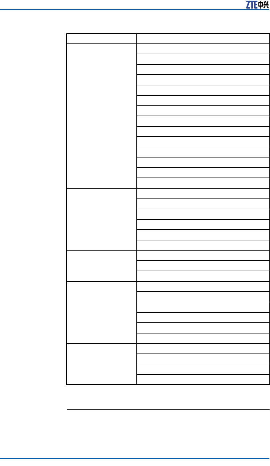
Thismanualcontainsthefollowingchaptersandappendixes:
ChapterSummary
Chapter
1Safety
Instruction
DescribesprecautionsinZXSDRR8860installationor
operationmaintenanceaswellasthemeaningsof
varioussafetysymbols.
Chapter2
Installation
Overview
DescribestherequirementsforZXSDRR8860
installationpersonnel,theinstallationowsand
installationpreparation.
Chapter
3Cabinet
Installation
DescribesfourinstallationmodesofZXSDRR8860
cabinetandinstallationsituations.
Chapter4
External
Cable
Installation
DescribestheinstallationmethodsofvariousZXSDR
R8860externalcables.
Chapter
5Main
Antenna
Feeder
System
Installation
Describestheinstallationowsandinstallationmethods
ofZXSDRR8860mainantennafeedersystem.
Chapter6
Hardware
Installation
Inspection
Describestheinspectionmethodsofcabinetandcables
afterinstallationcompletion.
ConfidentialandProprietaryInformationofZTECORPORATIONi

ZXSDRR8860InstallationManual
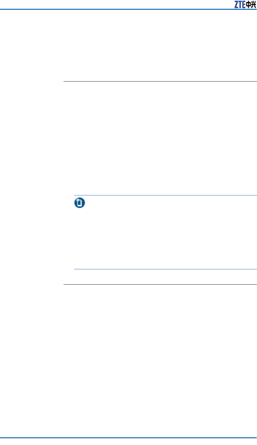
ChapterSummary
Chapter7
Poweron
andoff
DescribesthemethodsandprecautionsofZXSDR
R8860poweronandoff.
Appendix
ACabinet-
combined
Installation
DescribesthemethodofZXSDRR8860cabinet-
combinedinstallation.
AppendixB
Cascading
Cabinet
Installation
DescribesthemethodofZXSDRR8860cascading
cabinetinstallation.
AppendixC
OutdoorAC
UnitOAU
Describestechnicalindices,appearanceinterfaces,
installationintroductionandcableconnectionofOAU.
AppendixD
OutdoorDC
Lightning
Box
(OLP48–2)
Describestechnicalindices,appearanceinterfaceand
installationintroductionofoutdoorDClightningbox.
AppendixE
IndoorDC
Lightning
Box
(ILP48–3)
Describestechnicalindices,appearanceinterfaceand
installationintroductionofindoorDClightningbox.
Appendix
FAC
Lightning
Box
Describesappearanceinterfacesandcableconnection
ofAClightningbox.
Appendix
GPower
Distribution
Box(PDM)
Describesappearance,interfaceandinstallation
introductionofPDM.
iiConfidentialandProprietaryInformationofZTECORPORATION

Chapter1
SafteyDescription
TableofContents:
SafetySpecicationsGuide..................................................1
SafetySymbols..................................................................2
SafetyInstructions.............................................................3
SafetySpecificationsGuide
Thesesafetyinstructionsmustbeconsideredassupplementaryfor
localsafetyregulations.Theprioritymustbegiventolocalsafety
regulationsifthereisanyconictbetweenthetwo.
Themaintenancepersonnelmusthavetheknowledgeofsafety
operationsandmaintenancewithrequiredqualicationandtech-
nicalbackground.
Warning:
Thisdevicecomplieswithpart15oftheFCCRules.Operationis
subjecttothefollowingtwoconditions:(1)Thisdevicemaynot
causeharmfulinterference,and(2)thisdevicemustacceptany
interferencereceived,includinginterferencethatmaycauseunde-
siredoperation.Changesormodicationsnotexpresslyapproved
bythepartyresponsibleforcompliancecouldvoidtheuser’sau-
thoritytooperatetheequipment.
Alltheoperationandmaintenancepersonnelmustfollowthe
safetyprecautionsandinstructionsprovidedbyZTECorporation
toavoidanyaccident.
Note:
ZTECorporationdoesnotbearanyliabilitiesincurredbecauseof
violationoftheuniversalsafetyoperationrequirements,orviola-
tionofsafetystandardsfordesigning,manufacturingandusing
theequipment.
ConfidentialandProprietaryInformationofZTECORPORATION1
ZXSDRR8860InstallationManual
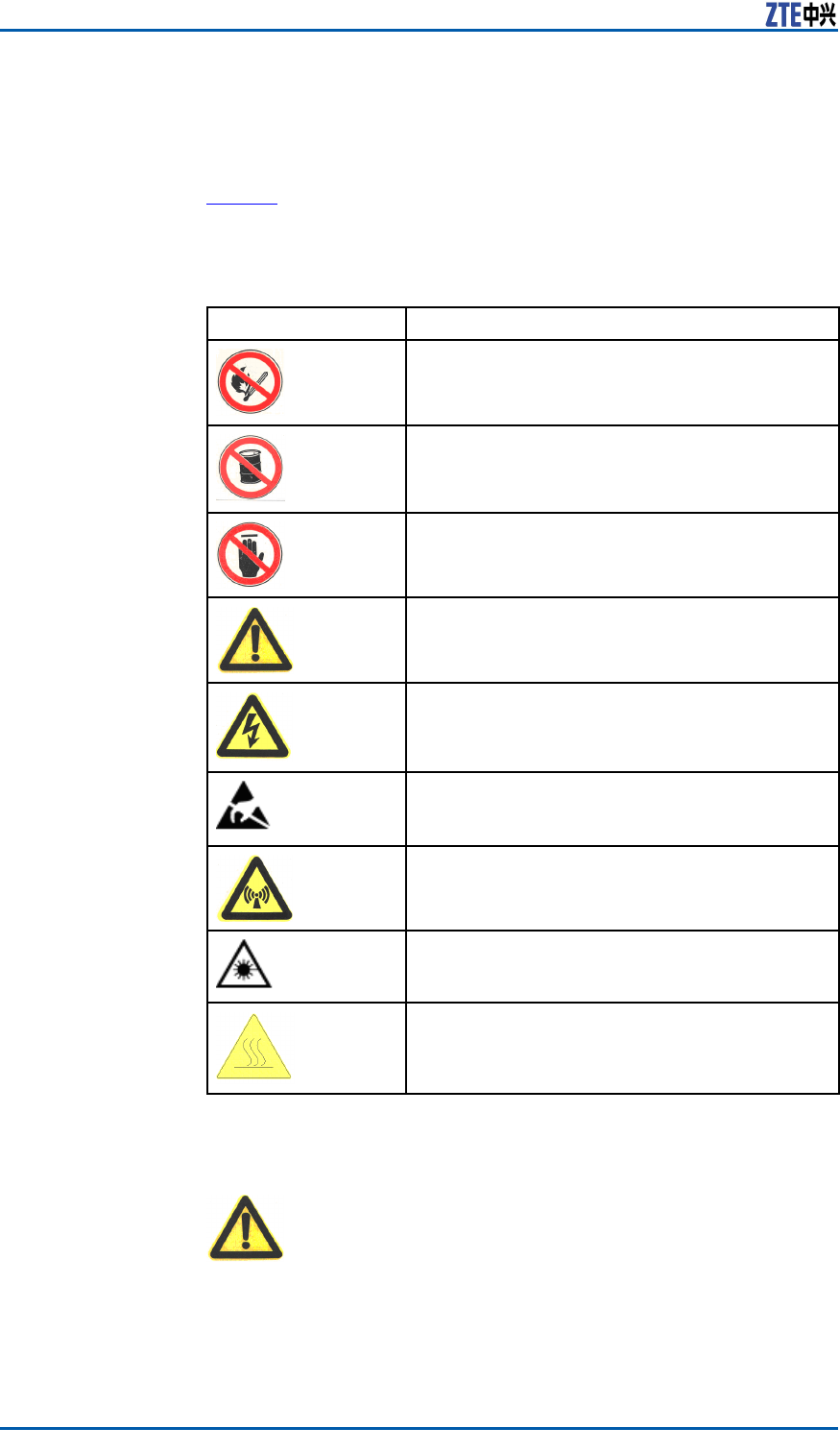
SafetySymbols
Table1listssafetysymbols.Theyaretoprompttheuserofthe
safetyprecautionstobeobservedduringZXSDRR8860operation
andmaintenance.
TABLE1SAFETYSYMBOLSDESCRIPTION
SafetySymbolsMeaning
Nosmoking:Smokingisforbidden
Noflammables:Noflammablescanbestored.
Notouching:Donottouch.
Universalalertingsymbol:Generalsafety
attentions.
Electricshock:Riskofelectricshock.
Electrostatic:Thedevicemaybesensitiveto
staticelectricity.
Microwave:Bewareofstrongelectromagnetic
field.
Laser:Bewareofstronglaserbeam.
Scald:Bewareofscald.
Amongstthesesafetysymbols,theuniversalalarmsymbolsare
classiedintothreelevels:danger ,warning,andcaution.The
formatsandmeaningsofthethreelevelsaredescribedasbelow:
Danger:
Indicatesapotentiallyhazardoussituationwhich,ifnotavoided,
willresultindeathorseriousinjuryofpeople,orequipmentdam-
agesandbreakdown.
2ConfidentialandProprietaryInformationofZTECORPORATION
Chapter1SafteyDescription
Warning:
Indicatesapotentiallyhazardoussituationwhich,ifnotavoided,
couldresultindeathorseriousinjury.
Caution:
Indicatesapotentiallyhazardoussituationwhich,ifnotavoided,
couldresultinseriousinjuries,equipmentdamagesorinterruption
ofpartservices.
SafetyInstructions
Thissectiondescribesthesafetyinstructionsrelatedtoelectrical
safety,antistatic,heavyobjectsandboards.
ElectricalSafety
Instructions
Thefollowingaretheelectricalsafetyinstructionsabouttools,high
voltage,powercables,holesandlightning:
�Tools
Usespecialtoolsratherthancommontoolsforhigh-voltage
andACoperations.
�HighVoltage
Danger:
Highvoltageishazardous.Directorindirectcontactwithhigh
voltageormainsupplyusingawetobjectcouldresultindeath.
�StrictlyfollowlocalsafetyrulestoinstallACpowerequip-
ments.
�Installationstaffmustbequaliedforperforminghigh-volt-
ageandACoperations.
�Donotwearanywatch,handchain,bracelet,ringorany
otherconductiveobjectduringsuchoperations.
�Preventmoisturefromaccumulatingontheequipmentdur-
ingoperationsinadampenvironment.
�PowerCable
ConfidentialandProprietaryInformationofZTECORPORATION3
ZXSDRR8860InstallationManual
Warning:
Neverinstalloruninstallpowercableswhiletheyarelive.Oth-
erwise,thepowercable,whencontactingaconductor ,mayre-
sultinsparksorelectricarccausingareorevendamageto
eyes.
�Makesuretoshutoffpowersupplybeforeinstallingordis-
connectingapowercable.
�Beforeconnectingthepowercable,makesurethatthecon-
nectingcableanditslabelisappropriatefortheactualin-
stallationrequirements.
�DrillingHoles
Warning:
Itisnotallowedtodrillcabinetholeswithoutpermission.
�Unqualieddrillingcoulddamagewiringandcablesinside
thecabinet.Additionally,metalpiecesinsidethecabi-
netcreatedbythedrillingcouldresultinashortedcircuit
board.Useinsulationprotectionglovesandmovecables
withinthecabinetawayrstwhendrillingisnecessaryon
acabinet.
�Protecteyesduringdrillingasdustoryingdebrismay
damageeyes.
�Cleananydebrisintimeafterdrilling.
�Lightning
Danger:
Donotperformhigh-voltage,AC,irontowerormastoperations
inathunderstorm.
Thunderstormswouldgiverisetoastrongelectromagnetic
eldintheatmosphere.Therefore,theequipmentmustbe
groundedandprotectedintimeagainstlightningstrikes.
AntistaticSafety
InstructionsElectrostatic:
Staticelectricityproducedbyhumanbodycandamagestatic-sen-
sitivecomponentsoncircuitboard,suchaslarge-scaleintegrated
circuits.
�Frictioncausedbyhumanbodyactivitiesistherootcauseof
electrostaticchargeaccumulation.Staticvoltagecarriedbya
humanbodyinadryenvironmentcanbeupto30kV ,and
canremaininthereforalongtime.Anoperatorwithstatic
4ConfidentialandProprietaryInformationofZTECORPORATION

Chapter1SafteyDescription
electricitymaydischargeelectricitythroughacomponentwhen
he/shetouchestheconductorandcausingdamage.
�Wearanantistaticwriststrap(theotherendofwriststrapmust
bewellgrounded)beforetouchingtheequipmentorholding
aplug-inboard,circuitboard,IntegratedCircuit(IC)chipor
otherdevices,topreventhumanstaticelectricityfromdamag-
ingsensitivecomponents.
�Aresistorover1MΩshouldbeconnectedinseriesonthecable
betweentheantistaticwriststrapandthegroundingpoint,to
protecttheoperatoragainstaccidentalelectricshock.Resis-
tanceover1MΩislowenoughtodischargestaticvoltage.
�Theantistaticwriststrapusedmustbesubjecttoregular
check.Donotreplacethecableofanantistaticwriststrap
withanyothercable.
�Donotcontactstatic-sensitiveboardswithanyobjectthateas-
ilygeneratesstaticelectricity.Forexample,frictionofpackage
bag,transferboxandtransferbeltmadefrominsulationplas-
ticmaycausestaticelectricityoncomponents.Dischargeof
staticelectricitymaydamagecomponentswhentheycontact
ahumanbodyortheground.
�Boardshouldonlycontactmaterialssuchasantistaticbag.
Keepboardsinantistaticbagsduringstorageandtransporta-
tion.
�Dischargestaticelectricityofthetestdevicebeforeuse,that
is,groundthetestdevicerst.
�DonotplacetheboardnearastrongDCmagneticeld,such
asthecathode-raytubeofamonitor .Keeptheboardatleast
10cmaway.
HoistingHeavy
Objects
Warning:
Whenhoistingheavyobjects,ensurethatnobodyisstandingor
walkingunderthehoistedobject.
�Ensurethehoistercanmeethoistingrequirementswhendis-
assemblingheavyequipment,ormovingandreplacingequip-
ment.
�Theoperatormustbedulytrainedandqualiedforhoisting
operations.
�Hoistingtoolsmustbeinspectedandcompletebeforeservice.
�Makesurethathoistingtoolsarexedrmlyonasufciently
securedobjectorwallbeforethehoistingoperation.
�Givebrieforalinstructionsduringhoistingoperationstopre-
ventanymishap.
Unplugging/Plug-
gingaBoard
�Neverplugaboardwithexcessiveforce,toensurethatthe
pinsonthebackplanedonotgetdeformed.
�Plugtheboardrightintotheslotandmakesureboardcircuit
facesdonotcontacteachotherlestanyshortcircuitmayoccur .
�Keephandsofftheboardcircuit,components,connectorsand
cabletroughwhenholdingaboard.
ConfidentialandProprietaryInformationofZTECORPORATION5

ZXSDRR8860InstallationManual
OtherSafety
Instructions
Note:
Donotperformmaintenanceordebuggingindependently,unless
aqualiedpersonispresent.
�Replacinganypartsormakinganychangestotheequipment
mightresultinanunexpecteddanger .Therefore,besurenot
toreplaceanypartsorperformanychangestotheequipment
unlessauthorizedotherwise.
�ContactZTEofceifyouhaveanyquestion,toensureyour
safety.
6ConfidentialandProprietaryInformationofZTECORPORATION

Chapter2
InstallationOverview
TableofContents:
ComponentstobeInstalled.................................................7
InstallationFlow.................................................................7
InstallationPreparation.......................................................8
ComponentstobeInstalled
ForZXSDRR8860,thefollowingcomponentswillbeinstalled:
�ZXSDRR8860cabinetandcomponents
Note:
Theinnercablesandfunctionalmodules/boardsinthecabinet
arealreadyinstalledbeforeequipmentdelivery.
�Sunshield(usedfortheoutdoorZXSDRR8860installation)
�Cables
�Antennafeedersystemincludingantenna,jumpersandfeeder
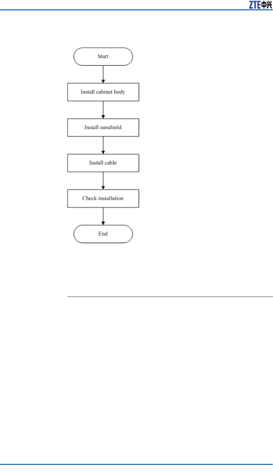
InstallationFlow
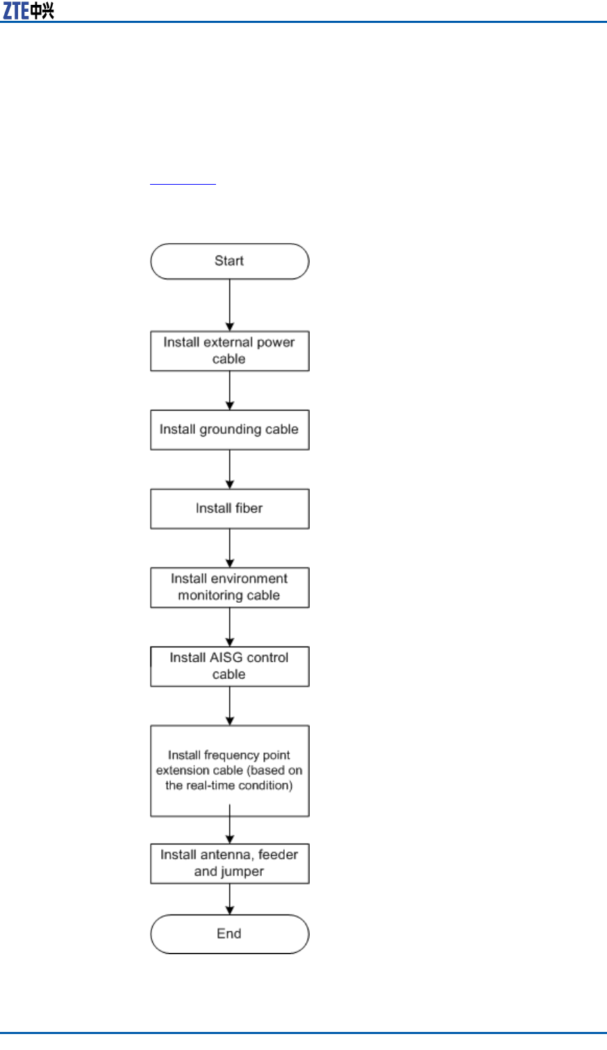
TheinstallationowofZXSDRR8860isdemonstratedinFigure1
.However ,itisnotrequiredtostrictlyfollowthestepsshowedin
thisow.Theactualinstallationproceduresdependontheonsite
requirements.
ConfidentialandProprietaryInformationofZTECORPORATION7
ZXSDRR8860InstallationManual
FIGURE1INSTALLATIONFLOW
InstallationPreparation
EngineeringConditionInspection
Beforeinstallingdevices,followtherequirementsofEnvironment
AcceptanceReportandcheckinstallationenvironment.Thefol-
lowingcontentisjustasareference.
Installation
Position
Inspection
ZXSDRR8860installationpositionshouldaccordwiththerequire-
mentsofengineeringdesign,thespeciedrequirementsasfol-
lows:
�Avoiddusty,harmful-gasorexplosive-goodsenvironment;
�Avoidtheplaceswithbigshockorstrongnoise;
�Farawaysubstation;
�Farawaypollutionsource;
�Avoidanindustrialboilerandheatingboiler;
�Farawayhigh-powerwirelessinterferencesource.
Temperature
andHumidity
Inspection
ZXSDRR8860temperatureandhumidityinworkenvironment
shouldmeettherequirements,asshownin
8ConfidentialandProprietaryInformationofZTECORPORATION

Chapter2InstallationOverview
PowerSupply
Inspection
TherequirementsofZXSDRR8860powersupplyaredescribedas
follows.
1.DCpowersupply:ZXSDRR8860is–48VDCpowersupplyand
thevoltageofpowersupplyis–40VDC~–57VDC.
2.IndirectACpowersupply:adoptanoutdoorACunit(OAU);
theOAUcanprovide220VACpowersupplyforoneZXSDR
B8200C100andoneZXSDRR8860atthesametime.
Lightning
Inspection
TheZXSDRR8860lightningrequirementsaredescribedasfollows.
�OutdoorInstallation
i.ForDCpowersupply,congureanoutdoorDClightningbox
OLP48-2.IftheDCpowerisexportedfromtheequipment
room,thelengthofpowercableismorethan10m(less
than50m)andtheoutputendofindoorDCpowerisnot
conguredwithB-levelorabovelightningdevices,itisre-
quiredtocongureanindoorDClightningboxILP48–3in
theequipmentroom.
ii.ForindirectACpowersupply,itisrequiredtocongurean
AClightningbox(ZXPCScombinedarrester).
�Forindoorinstallation,ifthepowercableisdistributedout-
doors,congurethepowerlightningboxaccordingtothecon-
ditionsofoutdoorinstallation.
Grounding
Inspection
ZXSDRR8860adoptsanassociatedgroundingmode.Thevalue
ofgroundingresistanceisnotmorethan5ohm.
OtherInspections1.Thecorollarydevicesorcomponentsshouldaccordwiththe
requirementsofZXSDRR8860engineeringdesigndrawing.
2.ThetransmissiondevicesinterconnectedwithBBUshouldhave
beenprepared.
ToolsandInstrumentsPreparation
Table2showstoolsandmeterslistrequiredduringinstallation.
TABLE2TOOLANDMETERLIST
CategoryName
Onefeederconnectorknife
Onewirestripper
Onecrimpingpliers
Special-purposetools
Onemulti-functionalcrimpingpliersEarth
resistancetester
Oneelectricpercussiondrill
Auxiliaryandsamplebits
Onevacuumcleaner
Concretedrillingtools
Powersocket(two-phaseandthree-phase
socket,withcurrentcapacitygreaterthan15
A)
ConfidentialandProprietaryInformationofZTECORPORATION9
ZXSDRR8860InstallationManual
CategoryName
Crossscrewdrivers(4”,6”and8”each)
Flatheadscrewdrivers(4”,6”and8”each)
Adjustablewrenches(6’ ,8’,10’and12’)
Dual-purposespanners(17”and19”each)
Onesetofsocketwrench
5kg(11lb)nailhammer
One300Wiron
One40Wiron
Solderwires
Hotblower
Oilpaintbrush
Pliers
Scissor
General-purposetools
Paperknife
One50m(164feet)tapemeasure
One5m(16feet)steeltape
One400mm(16inches)levelbar
Oneanglemeter
Onecompass
Measurementtools
Plumb
Antistaticwriststrap
Safetyhelmet
Protectiontools
Pairofgloves
Onehacksaw(withseveralsawblades)
Onepairofsharp-nosepliers(8″)
Onepairofdiagonalpliers(8″)
Onepairofslipjointpliers(8″)
Onepairofvices(8″)
Clamptools
Crowbar
Chainwheel
Rope
Ladder
Auxiliarytools
Forklift
On-siteDocuments
ZXSDRR8860installationneedsthefollowingtechnicaldocuments
tobeready.
10ConfidentialandProprietaryInformationofZTECORPORATION

Chapter2InstallationOverview
�ZXSDRR8860EngineeringExplorationReport
�ZXSDRR8860EnvironmentAcceptanceReport
ZXSDRR8860manualkitincludes:
�ZXSDRR8860CommissioningandCongurationManual
�ZXSDRR8860OperationandMaintenanceManual
�ZXSDRR8860TechnicalManual
UnpackingAcceptance
CountingGoods
PrerequisiteThetransportedcargoshouldhavereachedtheinstallationsite.
ContextTherepresentativeofcustomerandtheprojectsupervisormustbe
presentonsiteduringcountingofgoodsreceived.Ifanypartyis
notpresentatthattime,transportermustholdtheresponsibility
foranydiscrepanciesingoods.
Thestepsinvolvedincountinggoodsareasfollows:
Steps1.CheckDeliveryChecklistofZTECorporation.Checktotalnum-
berofgoods,intactnessofpackingboxes,andcheckwhether
arrivalplaceistheactualinstallationplaceagainstpackinglist
numberattachedtopackingboxes.Ifgoodsareintact,start
tounpackandinspectthem.
Note:
Itisrecommendedtounpackthegoodsafterabout30minutes
ofreceivingthecargo,sincethereisapossibilityofmoisture
contentduetotemperaturevariationsifany.
2.Equipmentinspectionlistandunpackingacceptancereportare
presentintherstpackingcarton.Firstly,openrstpacking
cartonandtakeouttheUnpackingAcceptanceReporttocheck
whetherthegoodsreceivedareinaccordancewiththeinspec-
tionlist.
3.Duringthecountingandunpackinginspectionprocess,ifany
materialisfoundshort,orgoodsdamaged,thenll-inUnpack-
ingAcceptanceFeedbackTableandcontactZTEpromptly.
ENDOFSTEPS.
CrateUnpacking
PrerequisitePreparetheappropriatetoolssuchasstraightscrewdriver ,pliers,
andcrowbar .
ContextPerformthefollowingstepstoopenthecrate:
ConfidentialandProprietaryInformationofZTECORPORATION11
ZXSDRR8860InstallationManual
Steps1.Insertastraightscrewdriverintotheslitbetweencrateand
frontcoverboardtomakeitloose;theninsertcrowbartoun-
clenchcoverboard.
2.Pullthecoverboardoutfromthecrate.
3.Removetheotherboardsofthecrate.
ENDOFSTEPS.
CartonUnpacking
PrerequisitePreparetheappropriatetoolssuchasstraightscrewdriver ,diago-
nalpliers,andpaperknife.
ContextPerformthefollowingstepstounpackthecarton:
Steps1.Usediagonalplierstocutpackingstraps.
2.Useapaperknifetocutadhesivetapealongtheslitsoncarton
cover ,avoiddamaginggoodsinside.
3.Openthecarton,andremovethefoamboard.
4.Checkthegoodswithinthecarton.
Note:
�Avoiddamagingtheantistaticbag(Itcanbeusedinthe
futureforstorageofspareparts)duringunpacking.
�Whiletheequipmentismovedtoahotteranddamper
place,waitfor30minutesbeforeunpackingtheequipment.
Otherwise,moisturemaycondenseonthesurfaceofthe
equipmentandcausedamage.
�Properlydisposeofrecycledesiccants.
ENDOFSTEPS.
AcceptanceandGoodsHandover
ContextPerformthisprocedureforacceptinggoods,andhandingthem
overtooperators.
Steps1.Acceptance
Baseduponthename,categoryandnumbermentionedonthe
shippinglist,carefullycheckthegoodspiecebypiece.Make
surethatgoodsfullthefollowingconditions:
i.Makesurethattherearenobubbly,peeling,nickandlth
markonthesurfaceofthechassis.
ii.Ensurethatoilpaintonthechassissurfaceisintact.
iii.Ensureclampingscrewsaretightandintact.
iv.Allthecomponentsareproperlyinstalledattheirrespective
positions.
12ConfidentialandProprietaryInformationofZTECORPORATION

Chapter2InstallationOverview
v.Laydowntheinspectedgoodsaccordingtocategories.
2.Handover
Aftercompletingtheunpackingprocedure,representativeof
customerandprojectsupervisorshouldapproveandsignUn-
packingforInspectionReport.Eachpartyshouldhaveacopy
ofUnpackingforInspectionReport.Ifthegoodsarestillun-
derthesupervisionoftheoperatorevenafteracceptance,then
goodswillnotbehandedovertotheoperatoruntilbothparties
signonthereport.
ENDOFSTEPS.
ConfidentialandProprietaryInformationofZTECORPORATION13

ZXSDRR8860InstallationManual
Thispageisintentionallyblank.
14ConfidentialandProprietaryInformationofZTECORPORATION

Chapter3
CabinetInstallation
TableofContents:
EngineeringIndices...........................................................15
InstallationModeInstruction...............................................16
Pole-mountedInstallationMode...........................................17
Wall-mountedInstallationMode...........................................33
FloorGantry-mountedInstallationMode...............................37
SimpliedCabinetIntegratedInstallationMode.....................54
InstallingSunshield..........................................................65
EngineeringIndices
Table3describestheengineeringindicesofZXSDRR8860.
TABLE3ZXSDRR8860ENGINEERINGINDICES
ItemIndices
OverallDimensionWidthxHeightxDepth:320mmx500mm
x172mm
UpperEnclosure
Dimension
WidthxHeightxDepth:320mmx370mm
x72mm
LowerEnclosure
Dimension
WidthxHeightxDepth:320mmx500mm
x100mm
Weight<22kg
Power-48VDC;-40V~-57V
220VAC:150V~285V/45Hz~65
Hz(viaexternalAC-to-DCconversion
lightningbox)
WorkTemperature-40℃to55℃-40℉to131℉
WorkHumidity5%RH~95%RH
PowerConsumptionof
NormalWorkUnder-48V
DCPowerSupply
�1Carrier
–OutputPower:20W/C/S
–PowerConsumption:170W
�2Carrier
–OutputPower:20W/C/S
–PowerConsumption:200W
�3Carrier
–OutputPower:20W/C/S
–PowerConsumption:230W
ConfidentialandProprietaryInformationofZTECORPORATION15
ZXSDRR8860InstallationManual
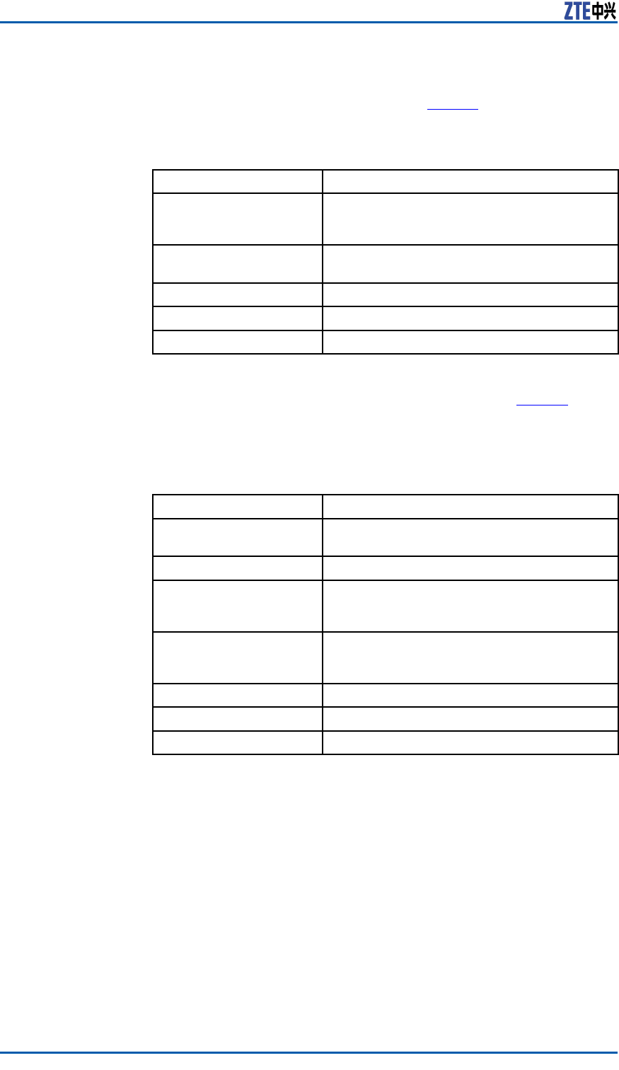
ThetechnicalindicesoftheindoorDClightningbox,exemplied
byJD40K085C20H2–K1Z,arelistedinTable4,whichissubjectto
theactualeldtechnicalspecicationsforpracticalapplication.
TABLE4JD40K085C20H2–K1ZDCLIGHTNINGBOXTECHNICALINDICES
ItemIndex
DimensionsWidthxHeightxDepth:400mmx450
mmx100mm(Theheightoftopcoverbox
lockexcluded)
NominalWorking
Voltage
–48V
InstallationModeIndoorwall-mountinstallation
WorkingTemperature-5℃to70℃
WorkingHumidity≤95%RH
ThetechnicalindicesoftheexternalAC-to-DCconversionlightning
box,exempliedbyGPAD501M54-1A,arelistedinT able5,which
issubjecttotheactualeldtechnicalspecicationsforpractical
application.
TABLE5GPAD501M54-1AEXTERNALAC-TO-DCCONVERSIONLIGHTNING
BOXTECHNICALINDICES
ItemIndex
DimensionsWidthxHeightxDepth:217mmx288
mmx127mm
Weight4.65kg
InputVoltageMin.value:150V
Typicalvalue:220V
Max.value:285V
InputFrequencyMin.value:45Hz
Typicalvalue:50Hz
Max.value:65Hz
InstallationModePole-mountandwall-mountinstallation
WorkingTemperature-40℃+65℃
WorkingHumidity5%95%
InstallationModeInstruction
Accordingtodifferentinstallationenvironments,therearethree
modesofZXSDRR8860installation:
�Pole-mountinstallation
�Wall-mountinstallation
�Gantry-mountinstallation
�Simplied-cabinetintegrativeInstallation
16ConfidentialandProprietaryInformationofZTECORPORATION

Chapter3CabinetInstallation
Pole-mountedInstallation
Mode
ComponentsUsedinPole-mount
Installation
Themaincomponentsusedinpole-mountinstallationinclude:
�Poleanchorclampcomponents;
�Polexingbracketcomponents.
Thepoleanchorclampcomponentsareusedforpole-mountin-
stallationofoneortwoZXSDRR8860s.Thepolexingbracket
componentsareusedforpole-mountinstallationofthreeZXSDR
R8860s.
Themainpoleanchorclampcomponentsusedinpole-mountin-
stallationforsingleZXSDRR8860arelistedinTable6
TABLE6MAINCOMPONENTLIST1
NameQuantity
Shortanchorclamp2
Longanchorclamp2
Standardspringwasher104
M10×120hexagonheadbolt(full
thread)
4
I-typecommonM10hexagonal
nut
4
Flatwasher104
Standardspringwasher84
M8×40hexagonheadbolt4
Bigwasher84
Themainpoleanchorclampcomponentsusedinpole-mountin-
stallationfortwoZXSDRR8860arelistedinTable7
TABLE7MAINCOMPONENTLIST2
NameQuantity
Longanchorclamp4
Standardspringwasher104
M10×120hexagonheadbolt(full
thread)
4
M10×80hexagonheadbolt(full
thread)
4
ConfidentialandProprietaryInformationofZTECORPORATION17
ZXSDRR8860InstallationManual
NameQuantity
I-typecommonM10hexagonal
nut
4
Flatwasher104
Standardspringwasher88
M8×40Hexagonheadbolt8
Bigwasher88
Themainpolexingbracketcomponentsusedinpole-mountin-
stallationforthreeZXSDRR8860arelistedinTable8
TABLE8MAINCOMPONENTLIST3
NameQuantity
Polefixingbracket4
Standardspringwasher104
M10×120hexagonheadbolt(full
thread)
4
I-typecommonM10hexagonal
nut
4
Flatwasher104
Standardspringwasher812
M8×40hexagonheadbolt12
Bigwasher812
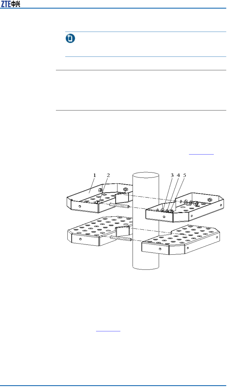
Figure2illustratespoleanchorclampcomponents.Figure3illus-
tratespolexingbracketcomponents.
FIGURE2POLEANCHORCLAMPCOMPONENTS
18ConfidentialandProprietaryInformationofZTECORPORATION
Chapter3CabinetInstallation
FIGURE3POLEFIXINGBRACKETCOMPONENTS
Note:
ThepoleanchorclampcomponentsshowninFigure2isadoptedin
onepole-mountinstallation.Thepoleanchorclampcomponents
usedintwopole-mountinstallationonlychangestwoshortanchor
clampsintotwolonganchorclamps,thespeciclistdescribedin
Table7
InstallingTwoZXSDRR8860C806
Pole-mountCabinets(WithoutWave
Trap)
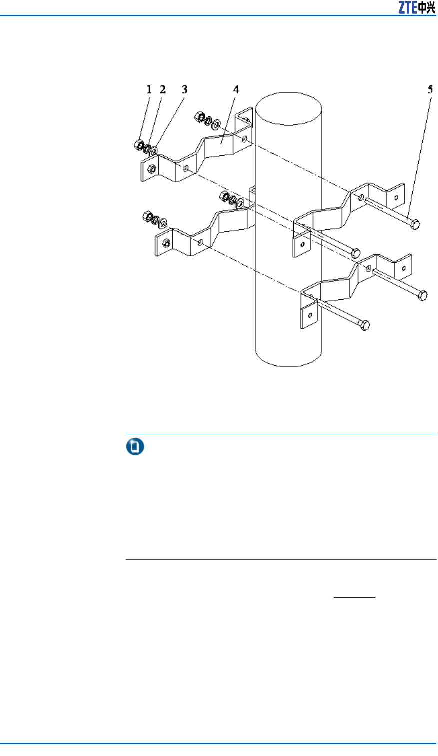
Steps1.Fixanchorclampsbacktobackontothepole,andalignthe
holesandscrewdownabitwithbolts.Adjustspacebetween
anchorclampsbasedonthescrews’positionofsupporting
panelasshowninFigure4.
ConfidentialandProprietaryInformationofZTECORPORATION19
ZXSDRR8860InstallationManual
FIGURE4POLE-MOUNTINSTALLATION(1)
1.I-typecommonM10hexago-
nalnut
2.Standardspringwasher10
3.Bigatwasher10
4.Longanchorclamp
5.M10×120hexagonheadbolt
(fullthread)
Tip:
DuringtwoZXSDRR8860cabinetinstallation,thesuggested
polediameteris60to120mmandtherearetwokindsofbolt
lengths:
�Usetheboltoflength80mmforpolediameterof60mm
to90mm;
�Usetheboltoflength120mmforpolediameterof90mm
to120mm.
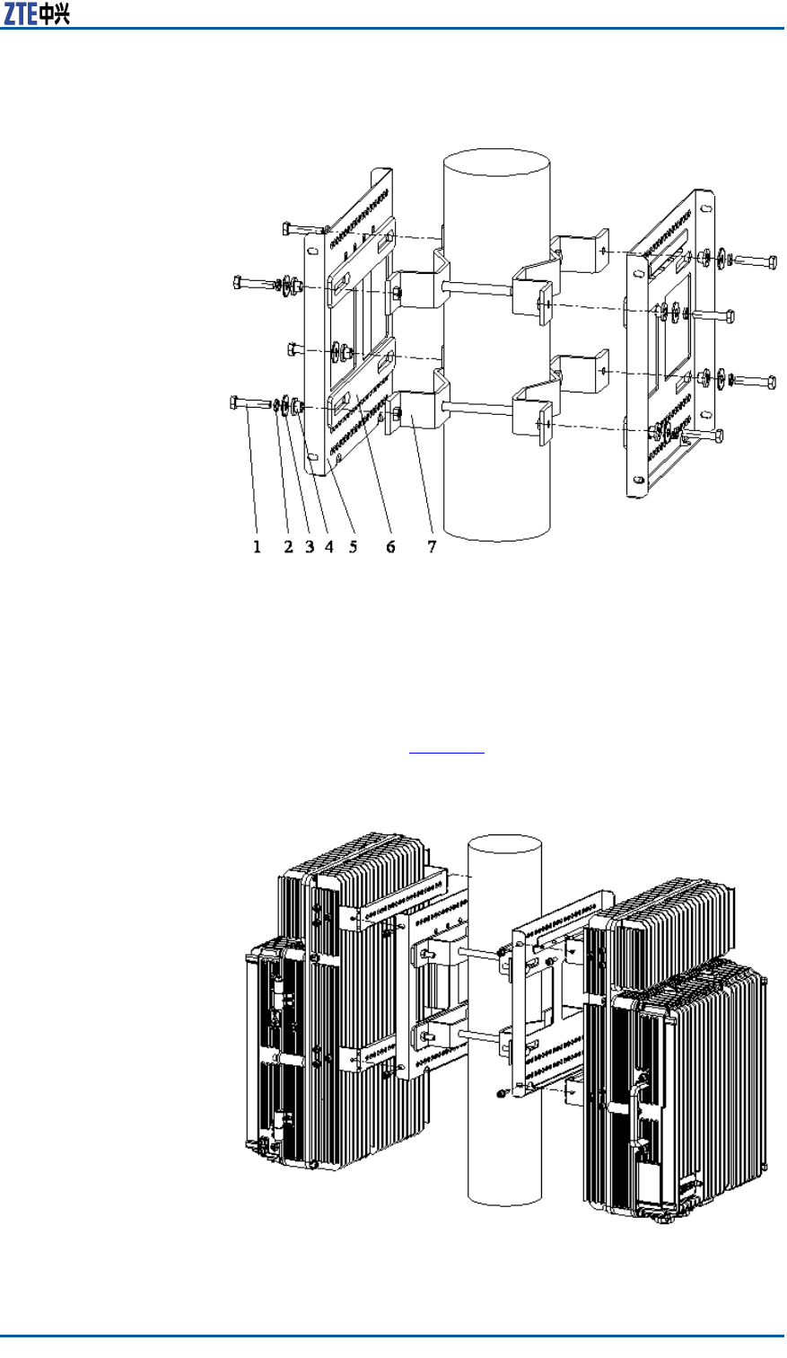
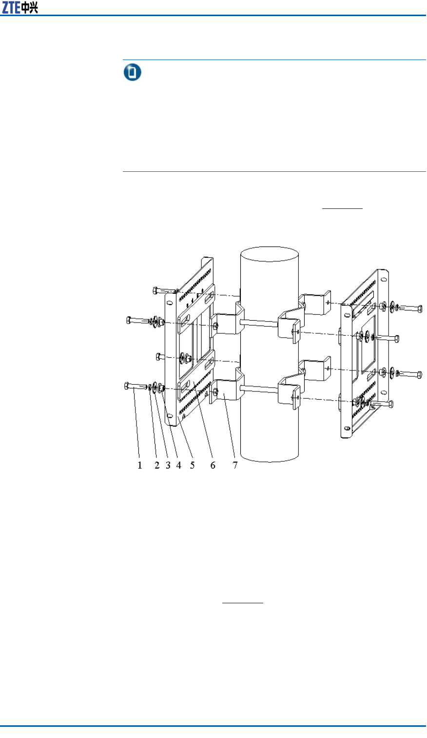
2.FixtwosupportingpanelsontheanchorclampwithM8bolts
andscrewM10boltstightly,asshowninFigure5.
20ConfidentialandProprietaryInformationofZTECORPORATION
Chapter3CabinetInstallation
FIGURE5POLE-MOUNTINSTALLATION(2)
1.M8×40Hexagonheadbolt
2.Standardspringwasher8
3.Bigatwasher8
4.Insulationange
5.Supportingpanel
6.Insulationboard
7.Longanchorclamp
3.MountthetwoZXSDRR8860cabinetsonthesupportingpanel
andfastenthecabinetwithfourM6X20hexagonsocketcap
screwsasshowninFigure6.
FIGURE6POLE-MOUNTINSTALLATION(3)
ConfidentialandProprietaryInformationofZTECORPORATION21
ZXSDRR8860InstallationManual
ENDOFSTEPS.
InstallingTwoZXSDRR8860C806
Pole-mountCabinets(WithWave
Trap)
ContextWhileinstallingtheZXSDRR8860C806pole-mountinstallation
withtwowavetraps,adoptanchorclamps;forthepole-mount
installationofthreewavetraps,adoptxingbrackets.
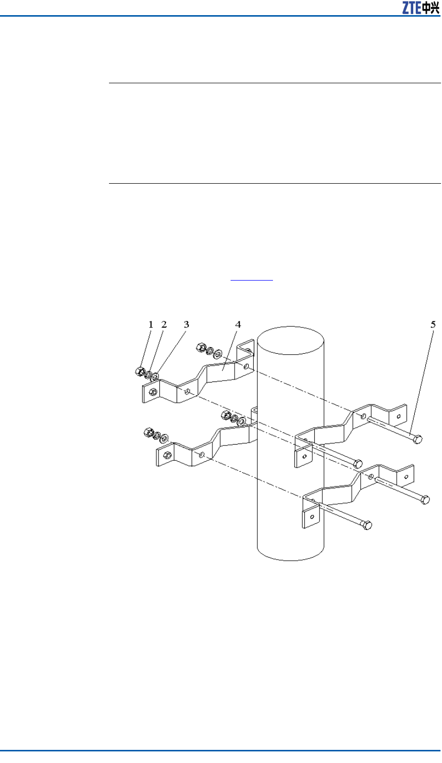
Steps1.Fixanchorclampsbacktobackontothepole,aligntheholes
andscrewdownabitwithbolts.Adjustspacebetweenanchor
clampsasshowninFigure7.
FIGURE7POLE-MOUNTINSTALLATION(1)
1.I-typecommonM10hexago-
nalnut
2.Standardspringwasher10
3.Flatwasher10
4.Longanchorclamp
5.M10×120hexagonheadbolt
(fullthread)
22ConfidentialandProprietaryInformationofZTECORPORATION
Chapter3CabinetInstallation
Tip:
DuringtwoZXSDRR8860installation,thesuggestedpoledi-
ameteris60to120mmandtherearetwokindsofboltlengths:
�Usetheboltoflength80mmforpolediameterof60mm
to90mm.
�Usetheboltoflength120mmforpolediameterof90mm
to120mm.
2.FixtwosupportingpanelsontheanchorclampswithM8bolts
andscrewdownM10bolts,asshowninFigure8.
FIGURE8POLE-MOUNTINSTALLATION(2)
1.M8×40hexagonheadbolt
2.Standardspringwasher8
3.Bigatwasher8
4.Insulationange
5.Supportingpanel
6.Insulationboard
7.Longanchorclamp
3.RepeattheStep1~Step2toinstalltwoanchorclampsandtwo
supportingpanels.
4.MountthetwoZXSDRR8860cabinetsontothesupportingpan-
elsandfastenthecabinetwithfourM6X20hexagonsocketcap
screwsasshowninFigure9.
ConfidentialandProprietaryInformationofZTECORPORATION23
ZXSDRR8860InstallationManual
FIGURE9POLE-MOUNTINSTALLATION(3)
5.Mountthetwowavetrapsontothesupportingpanelsandfas-
tenthemtothesupportingpanelswithfourM6X20hexagon
socketcapscrewsasshowninFigure10.
FIGURE10WAVETRAPINSTALLATION
1.Wavetrap
2.Fixingbeam
3.Supportingpanel
24ConfidentialandProprietaryInformationofZTECORPORATION
Chapter3CabinetInstallation
ENDOFSTEPS.
InstallingThreeZXSDRR8860C806
CabinetsonPole(WithoutWave
Trap)
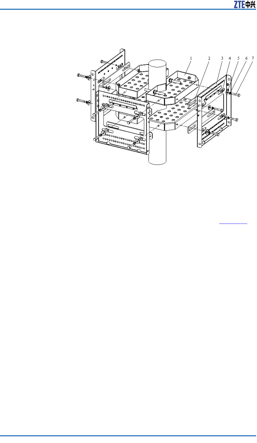
Steps1.Fixthetwosetsofxingbracketsontothepoleandalignthe
holesandscrewitabitwithbolts,asshowninFigure11
FIGURE11POLE-MOUNTINSTALLATION(1)
1.FixingBracket
2.M10×120hexagonheadbolt
(fullthread)
3.Standardspringwasher10
4.Flatwasher10
5.I-typecommonM10hexago-
nalnut
2.Adjustspacebetweenthexingbracketsbasedonthescrews’
positionofinsulationboardsatthebackofsupportingpanels
asshowninFigure12.Fixthreesupportingpanelsonthe
xingbracketswithM8bolts.Screwthexingbracketswith
M10bolts.
ConfidentialandProprietaryInformationofZTECORPORATION25
ZXSDRR8860InstallationManual
FIGURE12POLE-MOUNTINSTALLATION(2)
1.Fixingbracket
2.Insulationboard
3.Supportingpanel
4.Insulationange
5.Bigatwasher8
6.Standardspringwasher8
7.M8×40Hexagonheadbolt
3.MounttheZXSDRR8860cabinetsonthesupportingpanelsand
fastenthecabinetswithM6X20hexagonsocketcapscrewsas
showninFigure13.
FIGURE13POLE-MOUNTINSTALLATION(3)
26ConfidentialandProprietaryInformationofZTECORPORATION
Chapter3CabinetInstallation
Tip:
Thesidewithoutxingbracketcanbelocatedalongthewall.
ENDOFSTEPS.
InstallingThreeZXSDRR8860C806
CabinetonPole(WithWaveTrap)
ContextWhileinstallingtheZXSDRR8860C806pole-mountinstallation
withtwowavetraps,adoptanchorclamps;forthepole-mount
installationofthreewavetraps,adoptxingbrackets.
Steps1.Fixthetwosetsofxingbracketsontothepoleandalignthe
holesandscrewitabitwithbolts,asshowninFigure14.
FIGURE14POLE-MOUNTINSTALLATION(1)
1.FixingBracket
2.M10×120hexagonheadbolt
(fullthread)
3.Standardspringwasher10
4.Flatwasher10
5.I-typecommonM10hexago-
nalnut
2.Adjustspacebetweenthexingbracketsbasedonthescrews’
positionofinsulationboardsatthebackofsupportingpanels
asshowninFigure15.Fixthreesupportingpanelsonthexing
bracketswithM8bolts.Screwdownthexingbracketswith
M10bolts.
ConfidentialandProprietaryInformationofZTECORPORATION27
ZXSDRR8860InstallationManual
FIGURE15POLE-MOUNTINSTALLATION(2)
1.Fixingbracket
2.Insulationboard
3.Supportingpanel
4.Insulationange
5.Bigatwasher8
6.Standardspringwasher8
7.M8×40Hexagonheadbolt
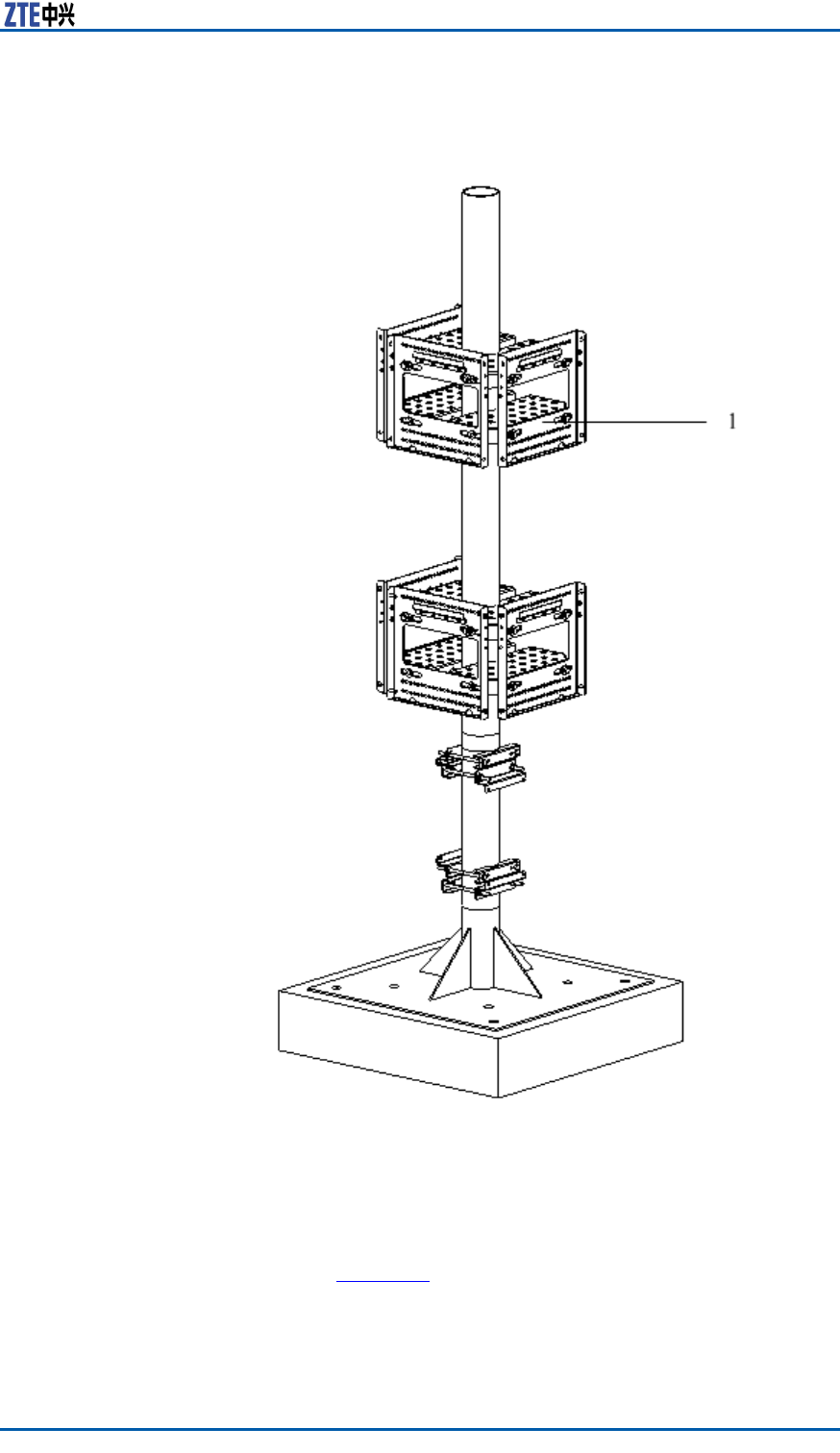
3.RepeattheStep1~Step2toinstalltwosetsofxingbrackets
andthreesetsofsupportingpanels,asshowninFigure16.
28ConfidentialandProprietaryInformationofZTECORPORATION
ZXSDRR8860InstallationManual
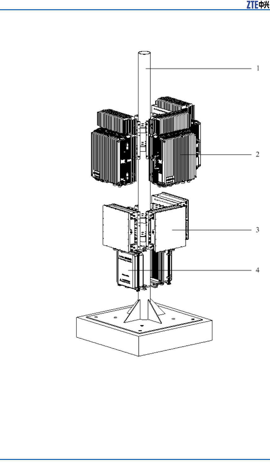
FIGURE19INSTALLATIONCOMPLETION
1.Pole
2.ZXSDRR8860
3.Wavetrap
4.LightningBox
32ConfidentialandProprietaryInformationofZTECORPORATION
Chapter3CabinetInstallation
Note:
InFigure19,anoutdoorDClightningboxoranAClightningbox
canbeadoptable.Theapplicationandinstallationforbothrefer
toAppendixCandAppendixE.
Wall-mountedInstallation
Mode
ComponentsUsedinWall-Mount
Installation
Thecomponentsusedinwall-mountinstallationarelistedinT able
9
TABLE9MAINCOMPONENTS
NameQuantity
Supportingpanel1
Drilltemplate1
M8×80expansionbolt4
Bigwasher84
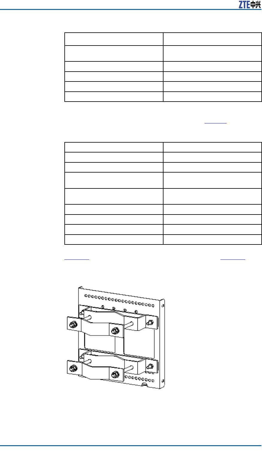
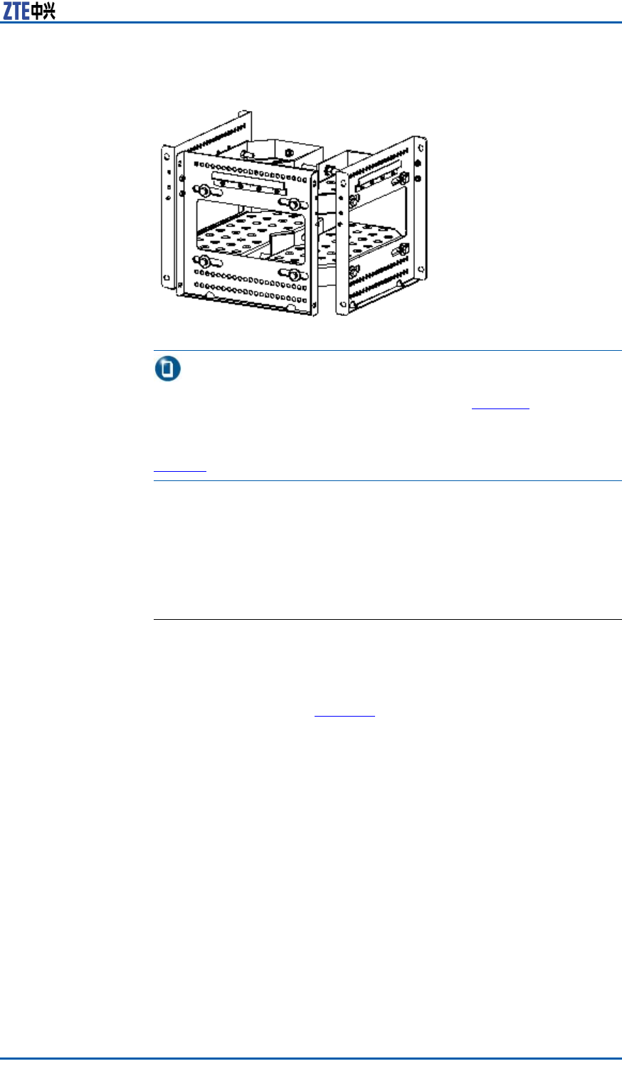
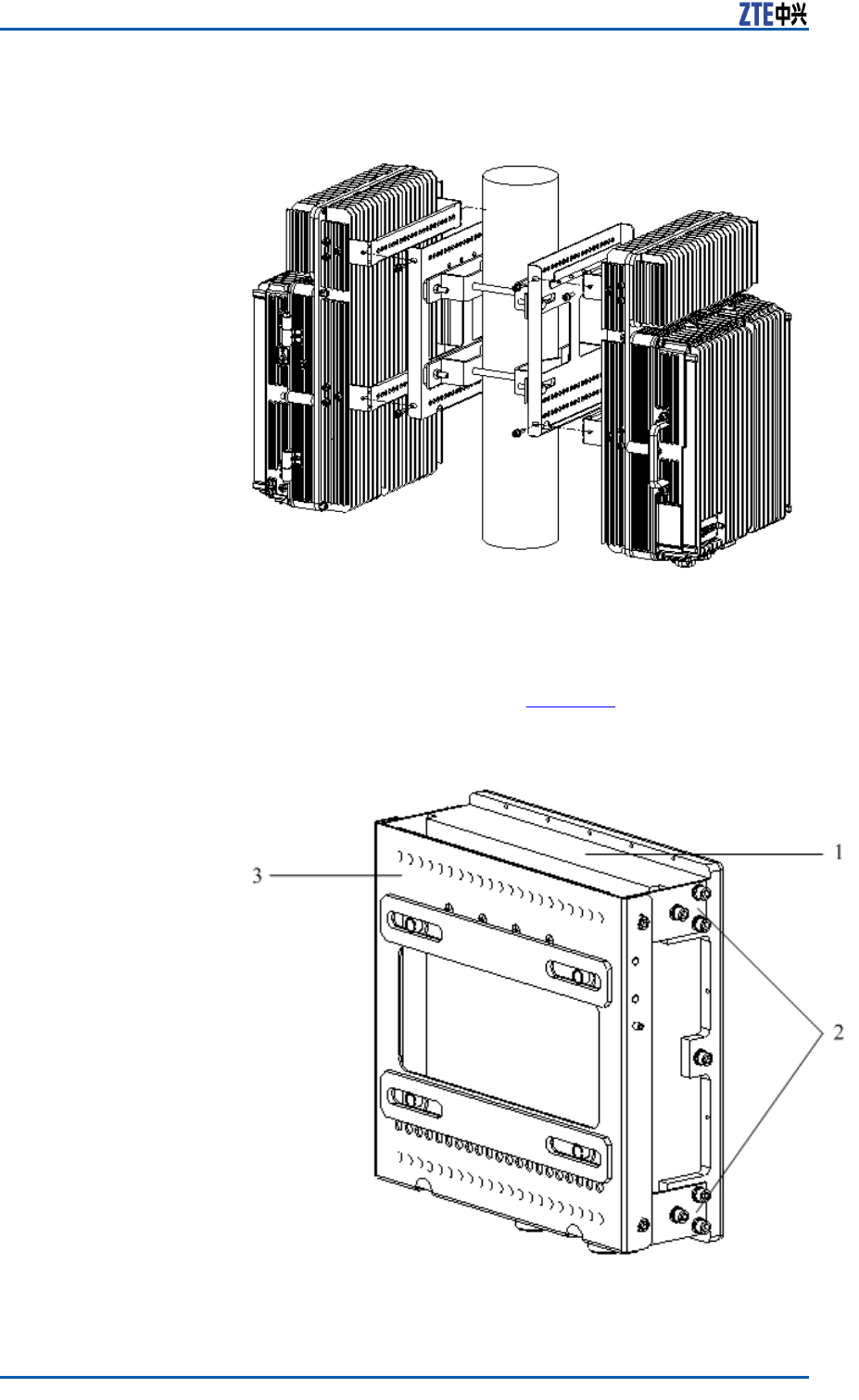
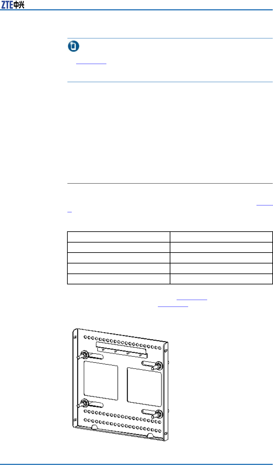
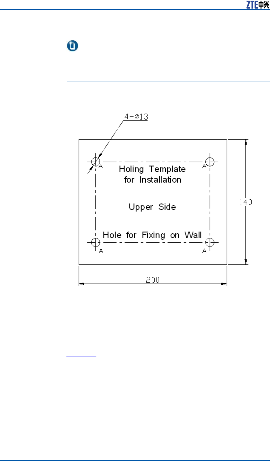
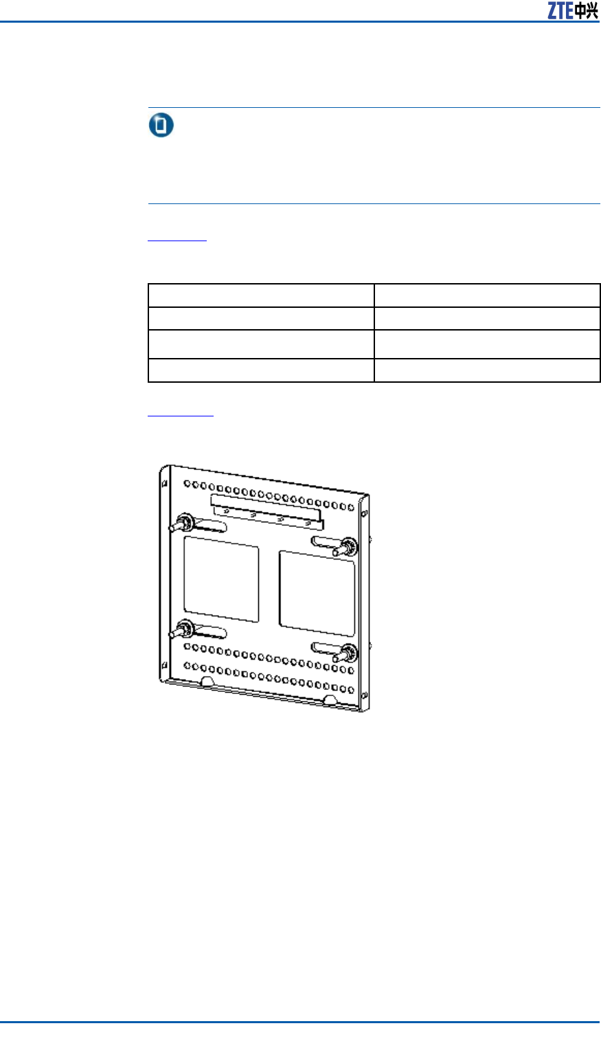
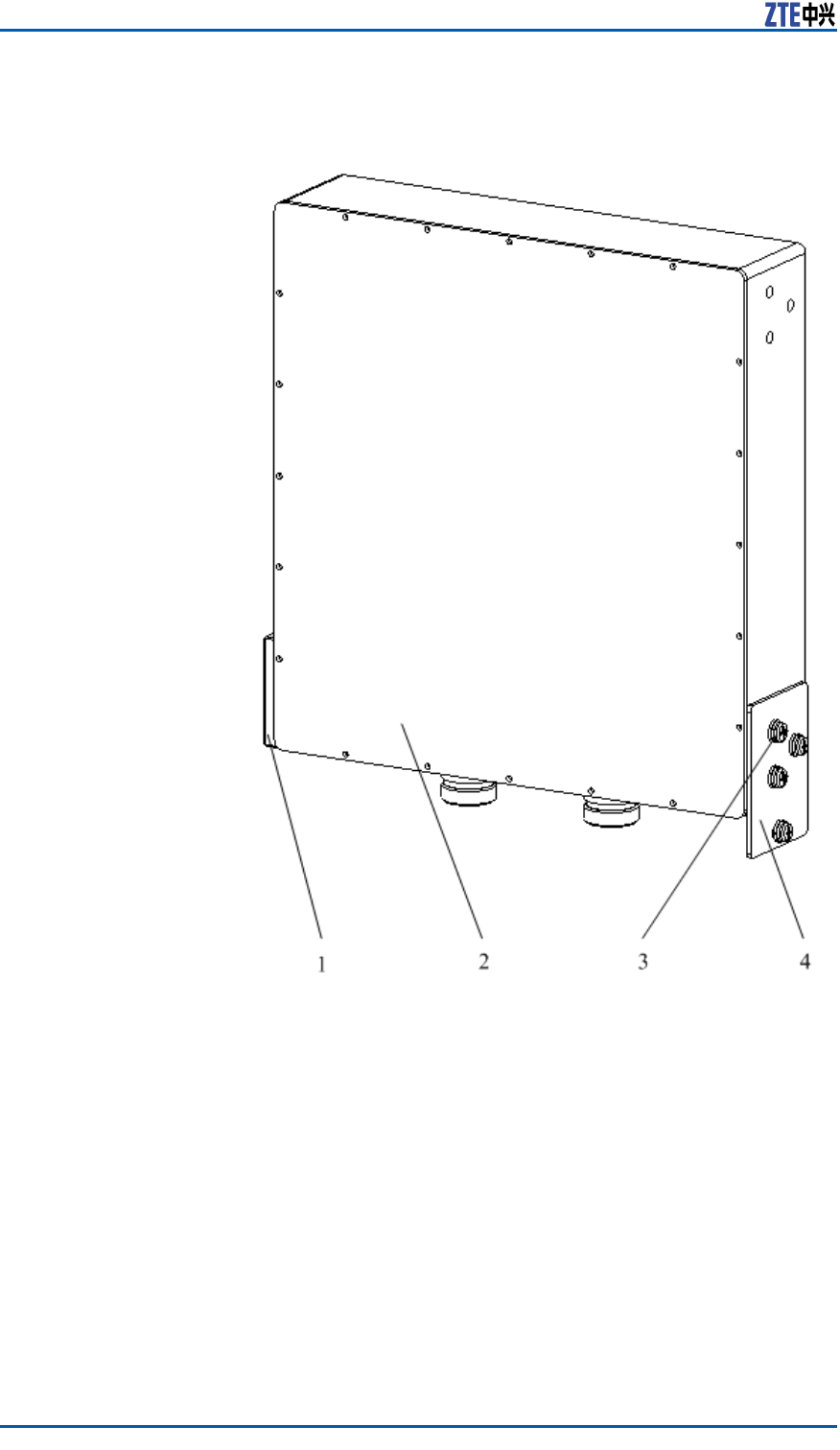
ThesupportingpanelisshowninFigure20.Theholemarking
designtemplateisshowninFigure21.
FIGURE20SUPPORTINGPANEL
ConfidentialandProprietaryInformationofZTECORPORATION33
ZXSDRR8860InstallationManual
Note:
Thesupportingpanel,asthecommoncomponentinZXSDRR8860
installation,isusedinthewall-mount,pole-mountandgantry-
mountinstallationmodes.
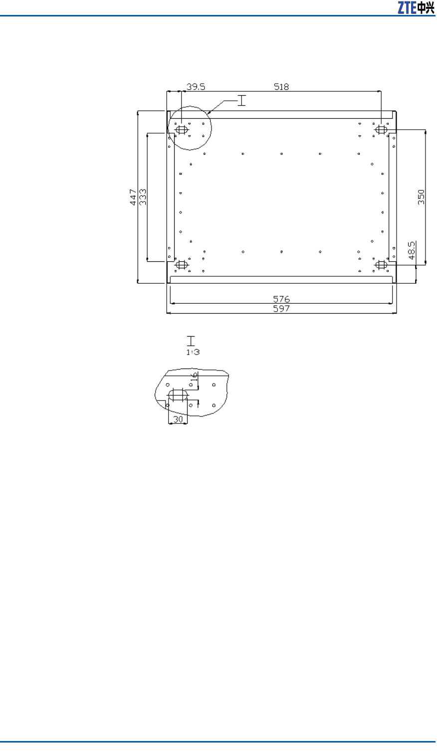
FIGURE21HOLEMARKINGDESIGNTEMPLATE(UNIT:MM)
InstallingCabinetonWall
(Wall-Mount)
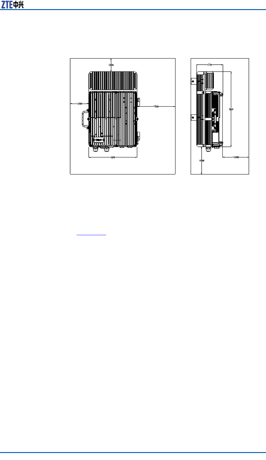
ContextFigure22illustratesthespacerequirement(Unit:mm)forwall-
mountinstallation.
34ConfidentialandProprietaryInformationofZTECORPORATION
Chapter3CabinetInstallation
FIGURE22SPACEREQUIREMENTFORWALL-MOUNTINSTALLATION(UNIT:
MM)
Steps1.Firstlymarktheholepositionsonthewallwithholedesign
template.Drillthemarkedpointsabout60mmwithpercussive
drillandinstalltheexpansionbolts.
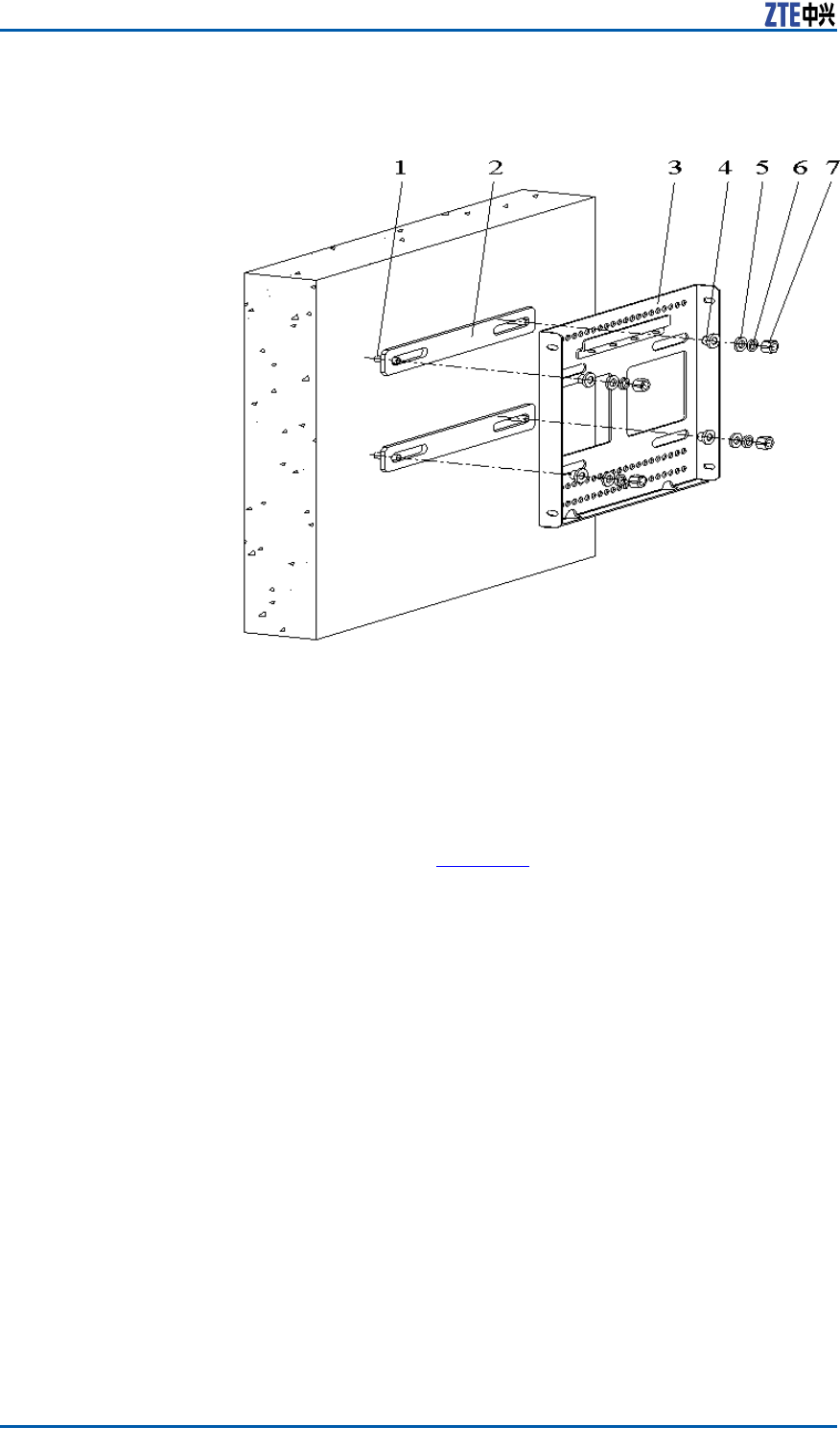
2.Fixthesupportingpanelonthewallwithboltsasshownin
Figure23
ConfidentialandProprietaryInformationofZTECORPORATION35
ZXSDRR8860InstallationManual
FIGURE23SUPPORTINGPANELINSTALLATIONONWALL
1.M8×80expansionbolt
2.Insulationboard
3.Supportingpanel
4.Insulationange
5.Bigatwasher8
6.Standardspringmat8
7.M8nut
l
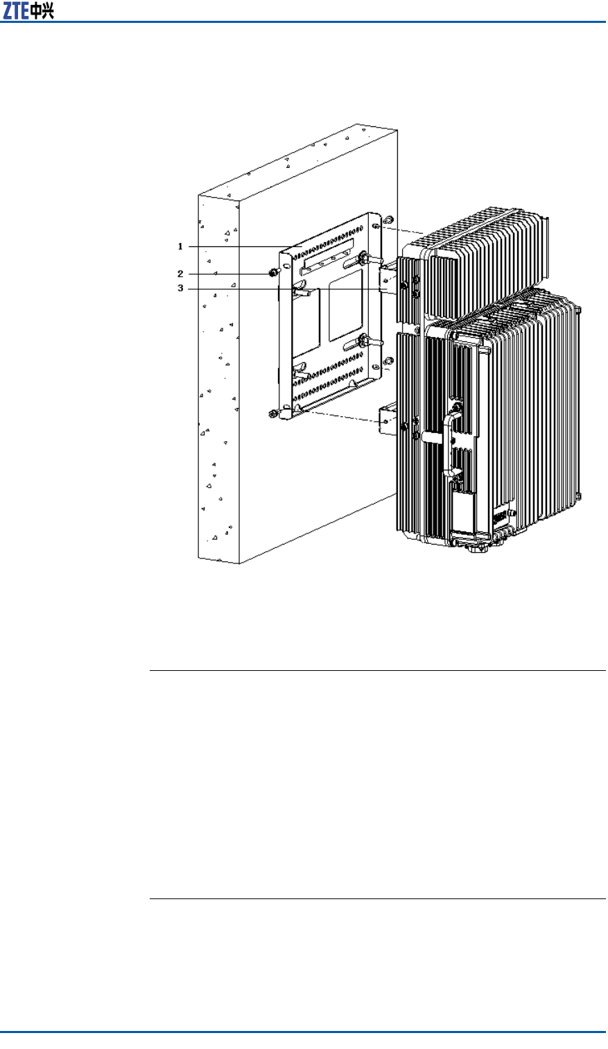
3.MounttheZXSDRR8860cabinetontothesupportingpanel,
andfastenthecabinetwithfourM6X20hexagonsocketcap
screwsasshowninFigure24.
36ConfidentialandProprietaryInformationofZTECORPORATION
Chapter3CabinetInstallation
FIGURE24MOUNTINGCABINET
1.Supportingpanel
2.M6safeguardscrew
3.Retainingboard
ENDOFSTEPS.
FloorGantry-mounted
InstallationMode
ComponentsUsedingantry-mount
Installation
Thecomponentsusedingantry-mountinstallationincludesa
gantryandsupportingpanels.Thequantityofsupportingpanels
isconsistentwiththatofZXSDRR8860s.ForeveryZXSDRR8860
cabinet,onesupportingpanelisrequired.
ConfidentialandProprietaryInformationofZTECORPORATION37

Chapter3CabinetInstallation
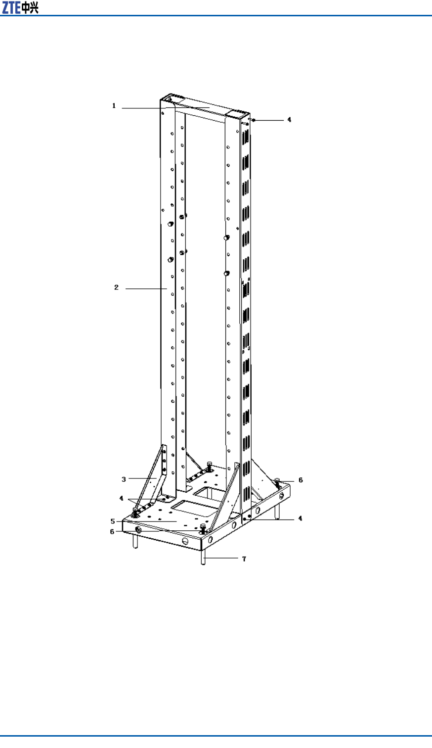
FIGURE25GANTRYAPPEARANCE
1.Coverplate
2.Uprightcolumn
3.Tiltedsupport
4.M5X16screw
5.Baseplate
6.M10X40tappingscrew
7.M10X100expansionbolt
ConfidentialandProprietaryInformationofZTECORPORATION39
ZXSDRR8860InstallationManual
Note:
AdopttheM10X100expansionboltwhileinstallingthegantryon
aconcretebaseplate;adopttheM10X40tappingscrewwhilein-
stallingthegantryinsideabunker .
Table11listssomecomponentsofsupportingpanel.
TABLE11MAINCOMPONENTS
NameQuantity
Supportingpanel1
M8×80expansionbolt4
Bigwasher84
Figure26showstheappearanceofsupportingpanel.
FIGURE26SUPPORTINGPANEL
40ConfidentialandProprietaryInformationofZTECORPORATION
Chapter3CabinetInstallation
Note:
Thesupportingpanel,asthecommoncomponentinZXSDRR8860
installation,isusedinthewall-mount,pole-mountandgantry-
mountinstallationmodes.
InstallingCabinetonGantry(Without
WaveTrap)
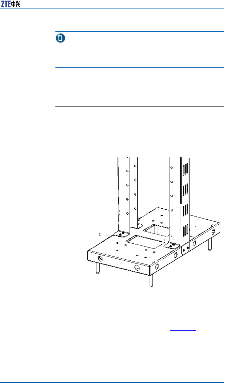
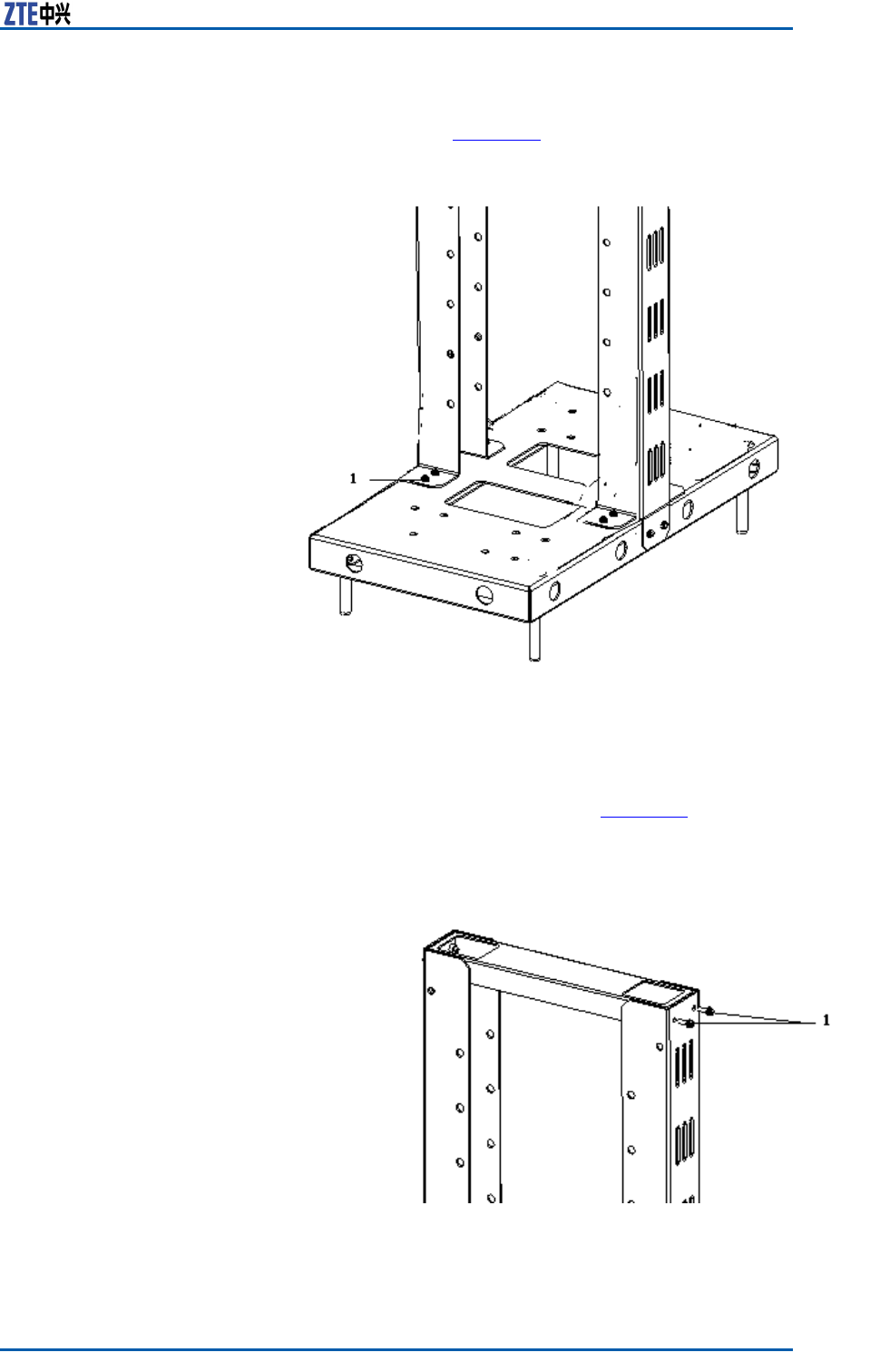
Steps1.Assemblethegantry
i.FixtheuprightcolumnuponthebaseplatewiththeM5X16
screws,asshowninFigure27.
FIGURE27FIXUPRIGHTCOLUMNANDBASEPLATE
1.M5X16screw
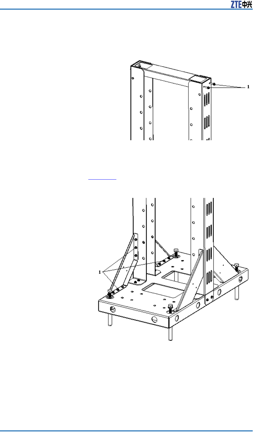
ii.Fastenthejunctionbetweenuprightcolumnandcoverplate
withtheM5X16screws,asshowninFigure28.
ConfidentialandProprietaryInformationofZTECORPORATION41
ZXSDRR8860InstallationManual
FIGURE28FASTENUPRIGHTCOLUMNANDCOVERPLATE
1.M5X16screw
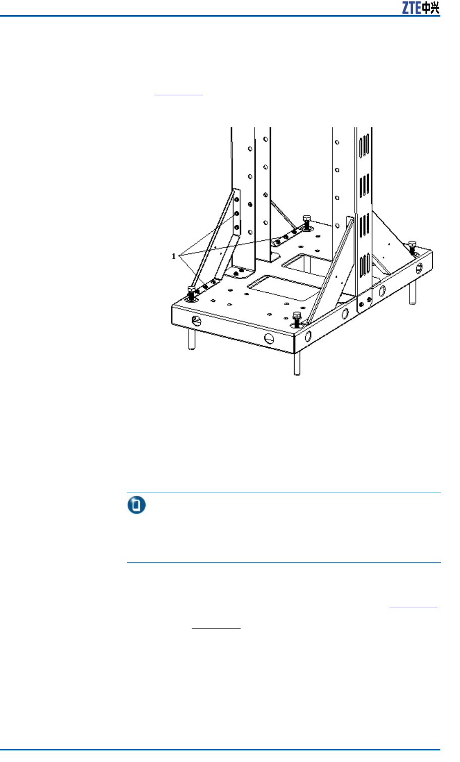
iii.FastenthetiltedsupportwiththeM5X16screws,asshown
inFigure29
FIGURE29FASTENTILTEDSUPPORT
1.M5X16screw
2.Installthegantry
Accordingtothespeciedinstallationpositionintheengineer-
ingdesigndrawing,drillthemarkedholesandinstalltheex-
pansionbolts.
42ConfidentialandProprietaryInformationofZTECORPORATION

Chapter3CabinetInstallation
Note:
AdopttheM10X100expansionboltwhileinstallingthegantry
onaconcretebaseplate;adopttheM10X40tappingscrew
whileinstallingthegantryinsideabunker .
3.InstalltheZXSDRR8860
i.Fastenthesupportingpanelsontotheproperpositionsof
gantrywithbolts.
ii.MounttheZXSDRR8860cabinetsontothesupporting
panels,andfastenthecabinetswithfourM6X20hexagon
socketcapscrews.
ENDOFSTEPS.
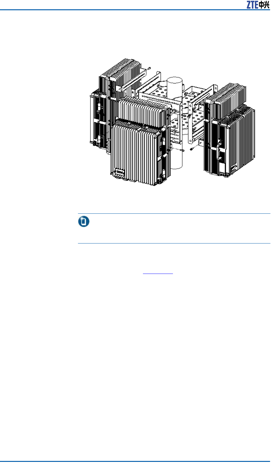
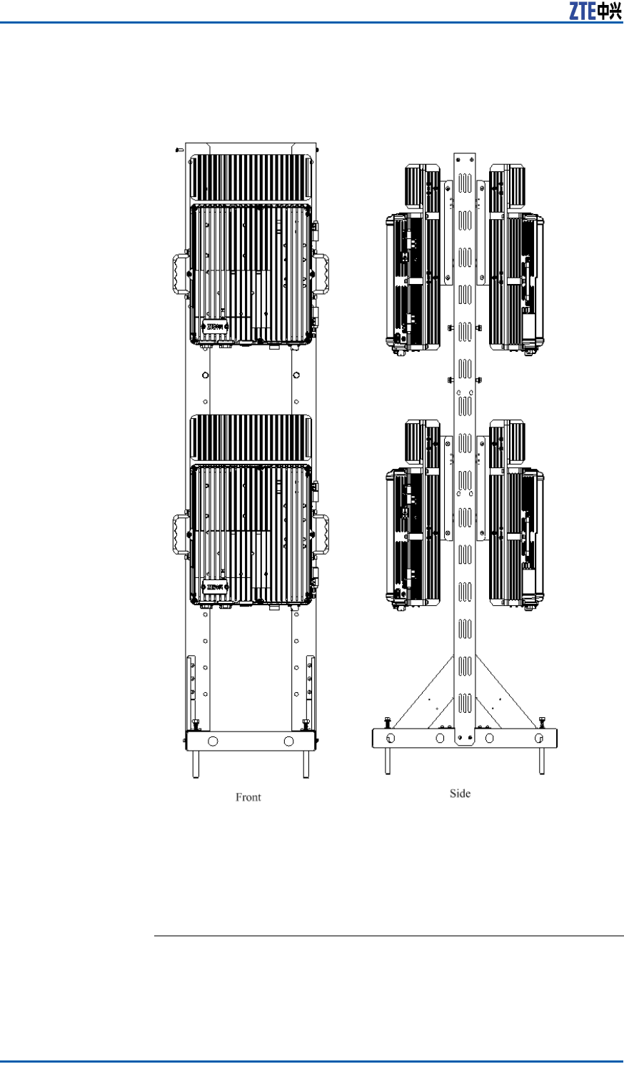
ExampleTheappearanceafterinstallationcompletionisasshowninFigure
30.
ConfidentialandProprietaryInformationofZTECORPORATION43
ZXSDRR8860InstallationManual
FIGURE30ZXSDRR8860INDOORGANTRY-MOUNTINSTALLATION
APPEARANCE(ONLYRRUINSTALLED)
InstallingCabinetonGantry(With
WaveTrap)
Steps1.Assemblethegantry.
44ConfidentialandProprietaryInformationofZTECORPORATION
Chapter3CabinetInstallation
i.FixtheuprightcolumnuponthebaseplatewiththeM5X16
screws,asshowninFigure31.
FIGURE31FIXUPRIGHTCOLUMNANDBASEPLATE
1.M5X16screw
ii.Fastenthejunctionbetweenuprightcolumnandcoverplate
withtheM5X16screws,asshowninFigure32.
FIGURE32FASTENUPRIGHTCOLUMNANDCOVERPLATE
1.M5X16screw
ConfidentialandProprietaryInformationofZTECORPORATION45
ZXSDRR8860InstallationManual
iii.FastenthetiltedsupportwiththeM5X16screws,asshown
inFigure33.
FIGURE33FASTENTILTEDSUPPORT
1.M5X16screw
2.Installthegantry.
Accordingtothespeciedinstallationpositionintheengineer-
ingdesigndrawing,drillthemarkedholesandinstalltheex-
pansionbolts.
Note:
AdopttheM10X100expansionboltwhileinstallingthegantry
onaconcretebaseplate;adopttheM10X40tappingscrew
whileinstallingthegantryinsideabunker .
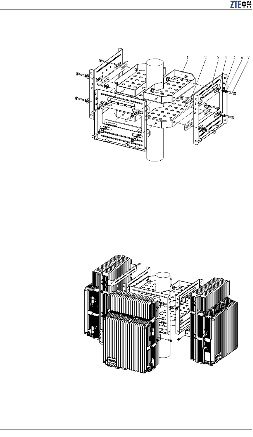
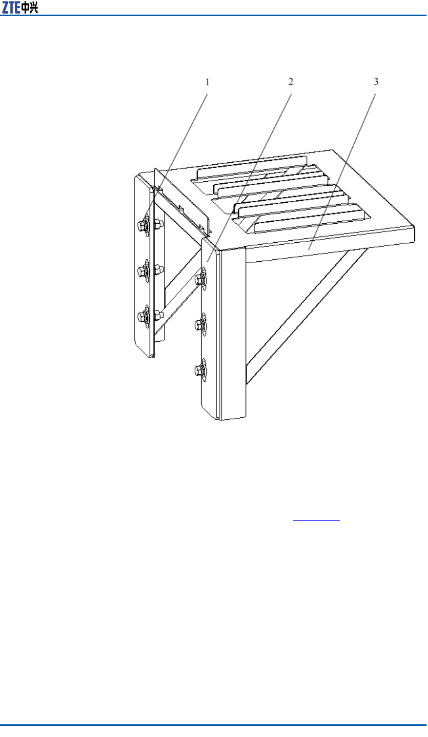
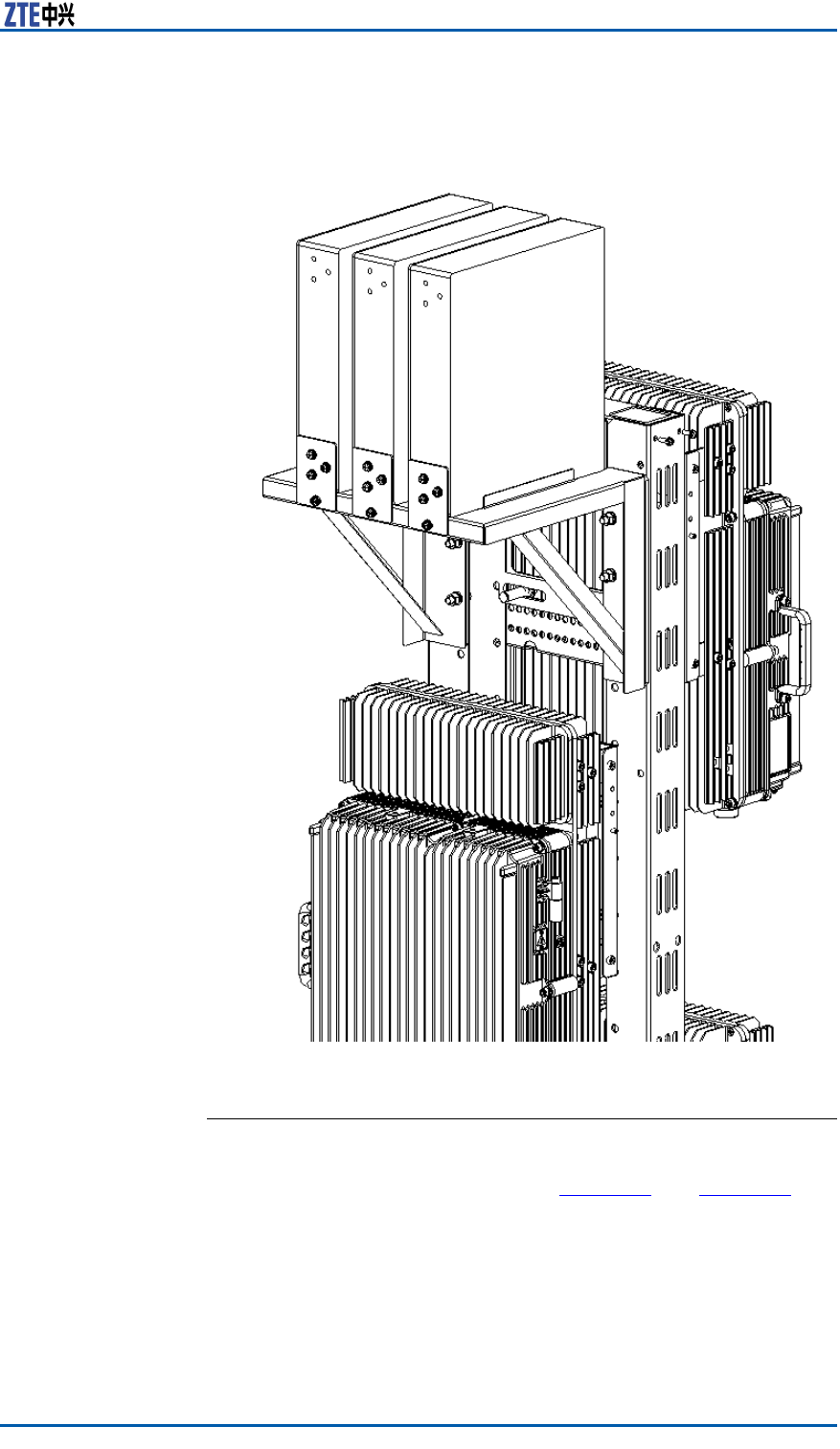
3.Installthesupportingbracketofwavetrap.
ThesupportingbracketofwavetrapisasshowninFigure34.
FastenthesupportingbracketontothegantrywithM8bolts,
asshowninFigure35.
46ConfidentialandProprietaryInformationofZTECORPORATION
ZXSDRR8860InstallationManual
FIGURE35SUPPORTINGBRACKETANDWALL-MOUNTASSEMBLIES
1.Gantry
2.Supportingbracket
3.Supportingpanel
4.BBUwall-mountframe
ii.MounttheZXSDRR8860cabinetsontothesupporting
panels,andfastenthecabinetswithfourM6X20hexagon
socketcapscrews,asshowninFigure36.
48ConfidentialandProprietaryInformationofZTECORPORATION
ZXSDRR8860InstallationManual
FIGURE37WAVETRAP
1.Guideblock
2.Wavetrap
3.M6bolt
4.Frontbafer
50ConfidentialandProprietaryInformationofZTECORPORATION
ZXSDRR8860InstallationManual
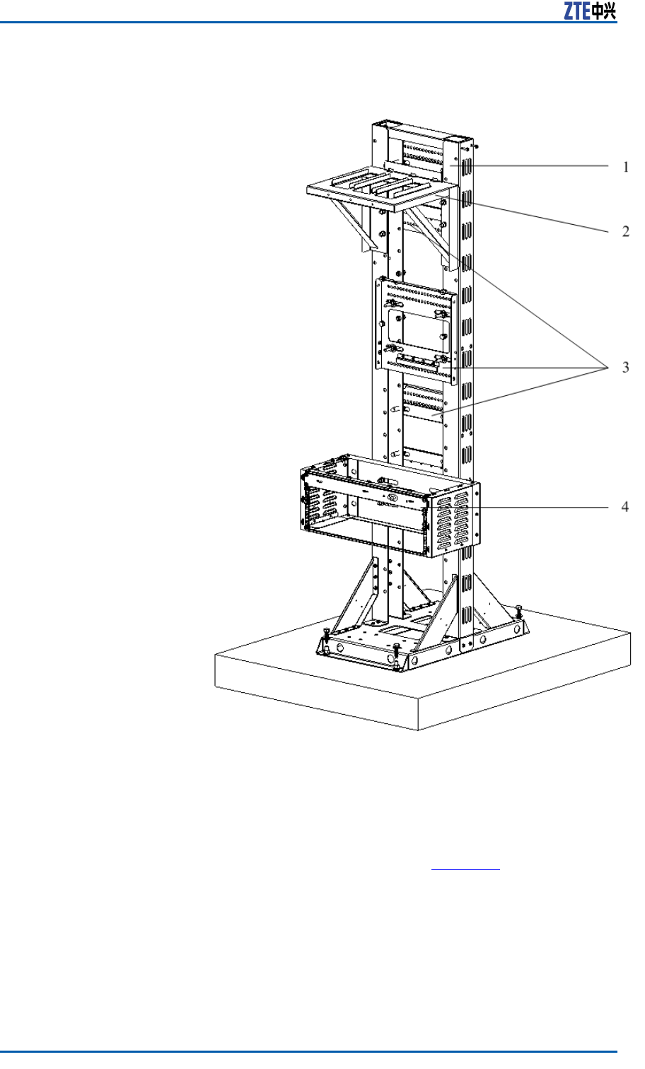
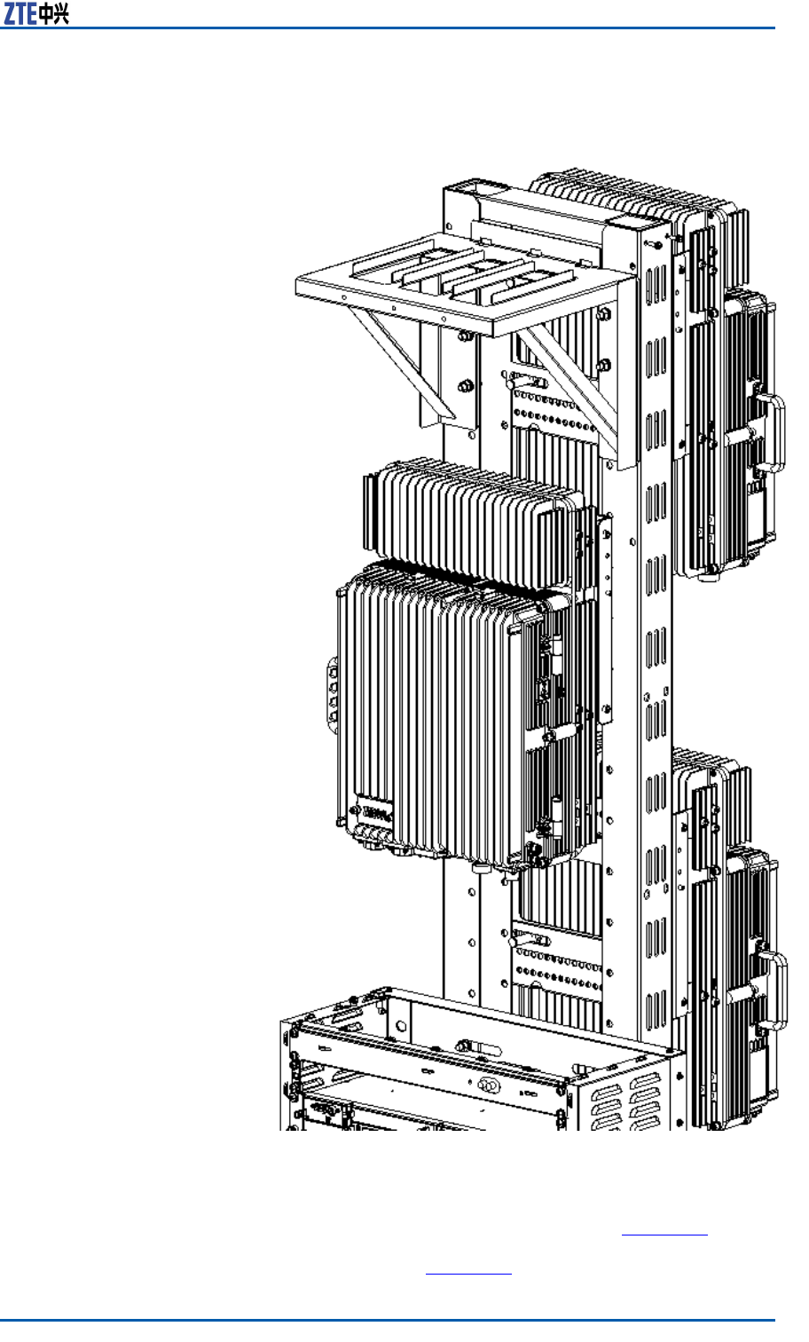
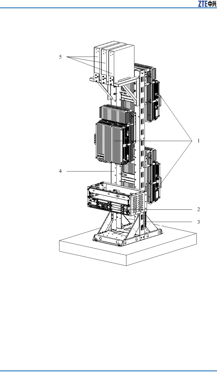
FIGURE39GANTRY-MOUNTINTEGRATEDINSTALLATION
1.ZXSDRR8860
2.ZXSDRB8200C100
3.Groundingcopperbar
4.Gantry
5.Wavetrap
52ConfidentialandProprietaryInformationofZTECORPORATION
Chapter3CabinetInstallation
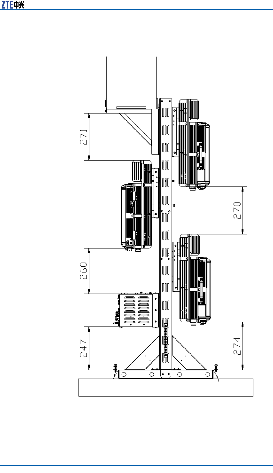
FIGURE40GANTRY-MOUNTINTEGRATEDINSTALLATION(SIDE)
ConfidentialandProprietaryInformationofZTECORPORATION53

ZXSDRR8860InstallationManual
SimplifiedCabinetIntegrated
InstallationMode
ComponentsUsedinIntegrated
Installation
TheZXSDRR8860forintegratedinstallationneedsthefollowing
components:asimpliedcabinet,anupperxingframeanda
lowerxingframe.
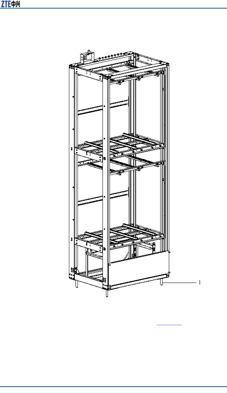
Thedimensionofsimpliedcabinetis1650×600×450(H×W×D;
unit:mm),asshowninFigure41.
54ConfidentialandProprietaryInformationofZTECORPORATION
Chapter3CabinetInstallation
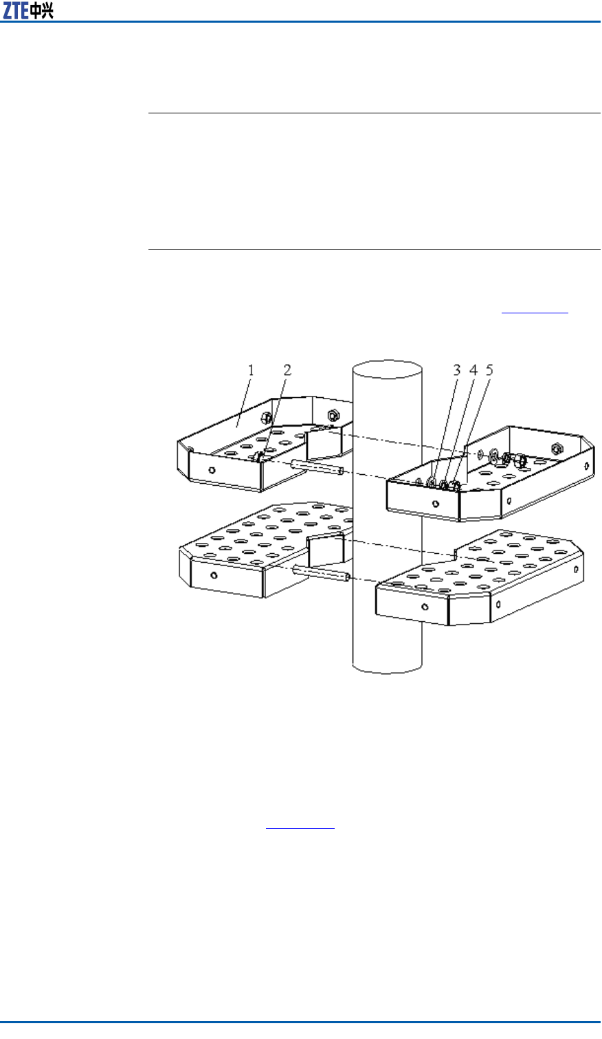
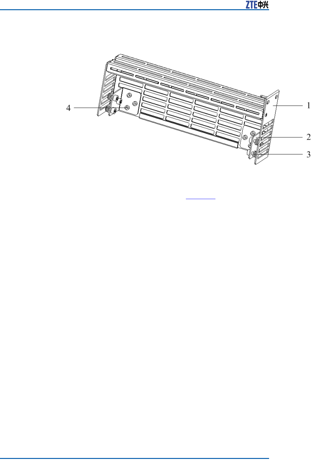
FIGURE43LOWERFIXINGFRAME
1.M6×16pan—headscrew
2.Supportingpanel1
3.M4×12pan—headscrew
4.Lowerxingframe
5.M6×16pan—headscrew
6.Supportingpanel2
InstallingIntegratedCabinet
PrerequisiteUnpackingandacceptancefortheZXSDRR8860andthesimplied
cabinetmeetrequirements.
Steps1.Installthesimpliedcabinet.
Accordingtoaninstallationpositionintheengineeringdesign
document,drillholesontheindooroor .Theholepositions
andthedimensionareasshownin.Fastenthecabinetonthe
oorwithM10×100expansionbolts.
ConfidentialandProprietaryInformationofZTECORPORATION57
ZXSDRR8860InstallationManual
FIGURE44HOLEPOSITIONSANDDIMENSION
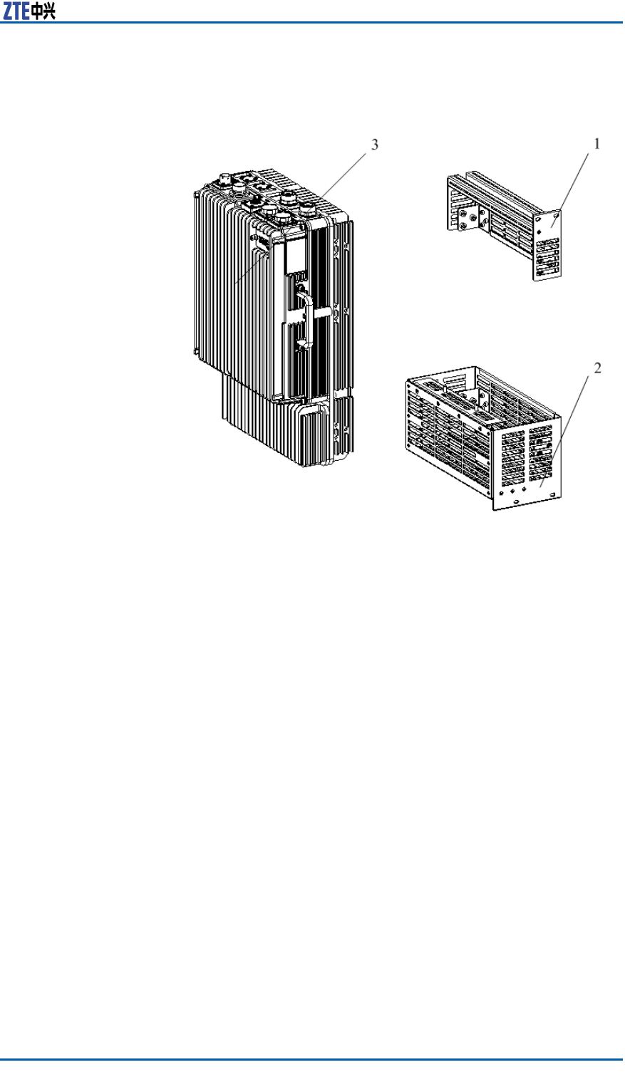
2.InstalltheZXSDRR8860.
showsallassembliesforZXSDRR8860integrated-cabinetin-
stallation.
58ConfidentialandProprietaryInformationofZTECORPORATION
Chapter3CabinetInstallation
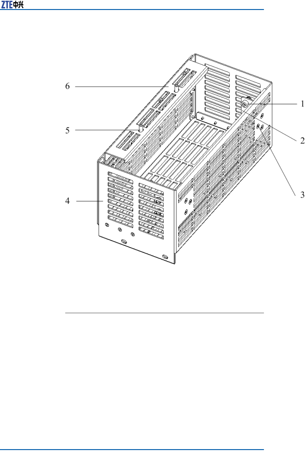
FIGURE45ZXSDRR8860ASSEMBLIES
1.Upperxingframe
2.Lowerxingframe
3.ZXSDRR8860
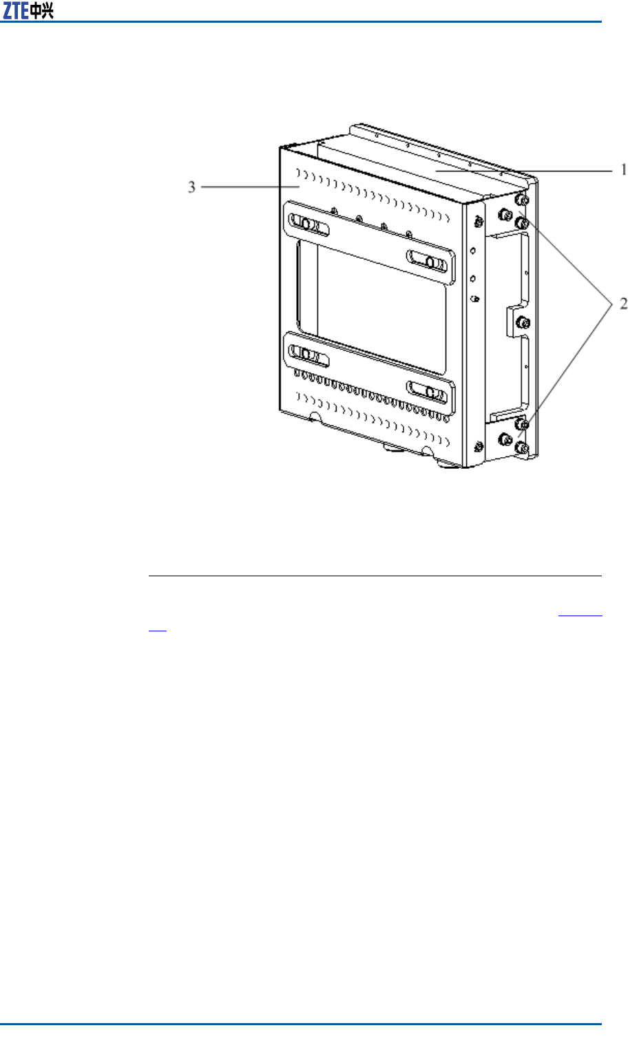
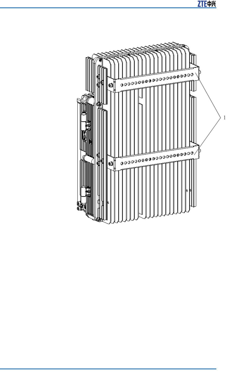
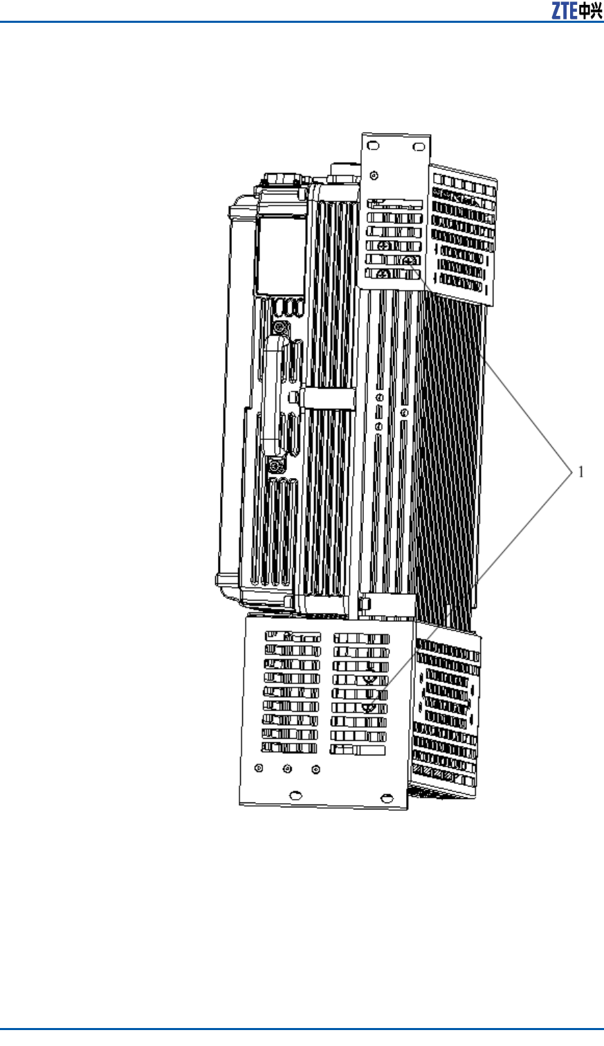
i.RemovethexingbeamsofZXSDRR8860.
TheZXSDRR8860carriestwoxingbeamsusedforwall-
mountandpole-mountinstallations,asshownin.Remove
thexingbeams.
ConfidentialandProprietaryInformationofZTECORPORATION59
ZXSDRR8860InstallationManual
FIGURE46ZXSDRR8860FIXINGBEAM
1.Fixingbeam
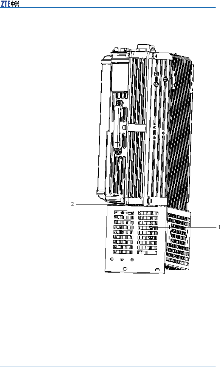
ii.Installthelowerxingframe.
InserttheZXSDRR8860tothelowerxingframe.Fasten
thesupportingpanel2withtheZXSDRR8860byM6×12
pan-headscrewsandfastenthesupporting1withZXSDR
R8860byM6×16pan-headscrews,asshownin.
60ConfidentialandProprietaryInformationofZTECORPORATION
Chapter3CabinetInstallation
FIGURE47LOWERFIXINGFRAMEINSTALLATION
1.Pan-headscrewM6×162.an-headscrewM6×12
iii.Installtheupperxingframe.
InserttheZXSDRR8860tothelowerxingframe.Fasten
thesupportingpanelofupperxingframewiththeZXSDR
R8860byM6×16pan-headscrews,asshownin.
ConfidentialandProprietaryInformationofZTECORPORATION61
ZXSDRR8860InstallationManual
FIGURE48ZXSDRR8860INSTALLEDWITHUPPERANDLOWER
FIXINGFRAME
1.M6×16pan-headscrew
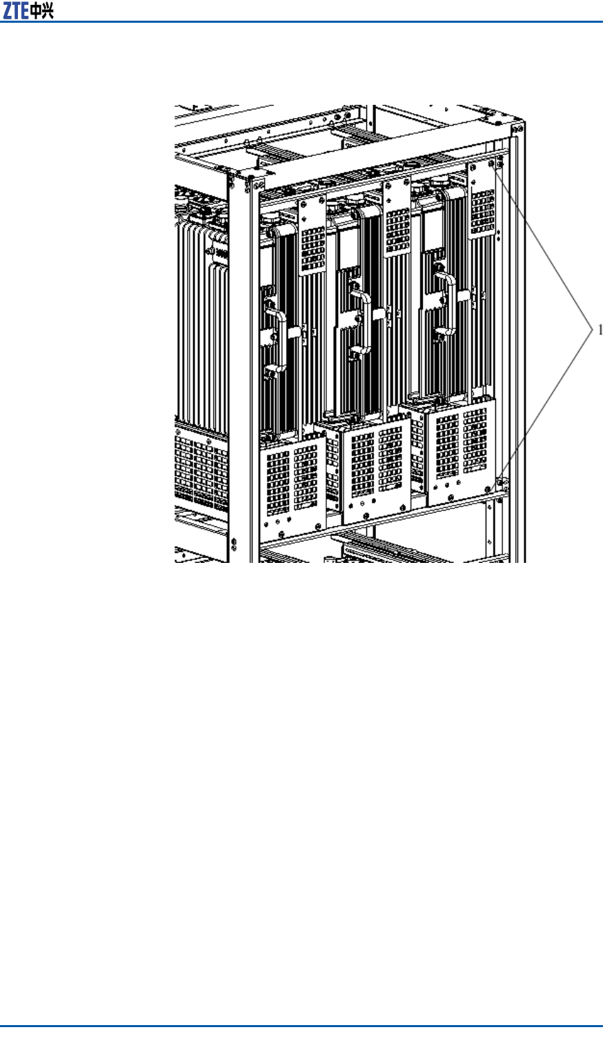
3.InstalltheZXSDRR8860tothesimpliedcabinet.
AligntheguidancechannelontheZXSDRR8860installedwith
theupperandlowerxingframestotherailonethesimplied
cabinet.ThenslidetheZXSDRR8860slowlyintothesimplied
cabinetandfastenthemwithfourM6×16pan-headscrews,as
shownin.
62ConfidentialandProprietaryInformationofZTECORPORATION
Chapter3CabinetInstallation
FIGURE49ZXSDRR8860INSTALLATIONTOSIMPLIFIEDCABINET
1.M6×16pan-headscrew
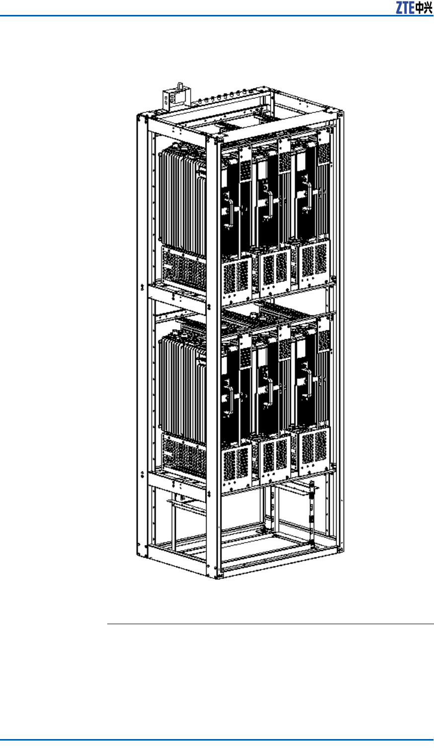
4.InstallotherZXSDRR8860s.
RepeattheStep2~Step4toinstallotherZXSDRR8860sinto
thesimpliedcabinet.WhensixZXSDRR8860sareinstalled
completely,theappearanceisasshownin.
ConfidentialandProprietaryInformationofZTECORPORATION63
ZXSDRR8860InstallationManual
FIGURE50ZXSDRR8860INSTALLATIONCOMPLETION
ENDOFSTEPS.
64ConfidentialandProprietaryInformationofZTECORPORATION
Chapter3CabinetInstallation
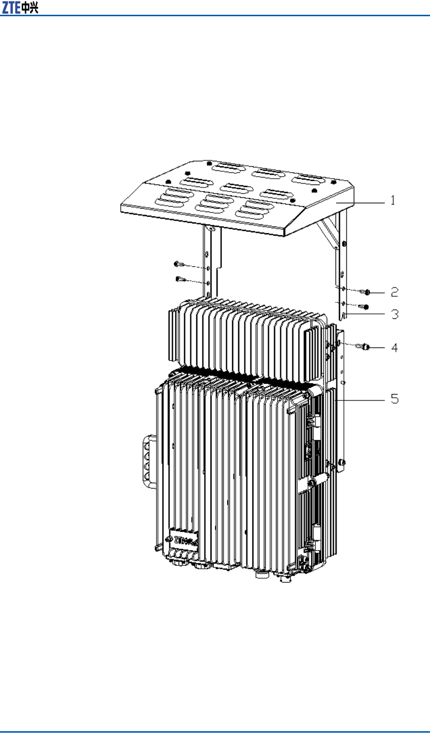
InstallingSunshield
ContextThecomponentsusedforinstallingsunshademustbeprepared.
showsthesunshadetobeinstalled.
FIGURE51SUNSHIELDSTRUCTURE
1.Sunshield
2.M5screw
3.Fixingposition(wedgedontothe
boltatthesideofthecommonpart
forwallmounting)
4.M6screw
5.ZXSDRR8860cabinet
Steps1.Assemblethesunshadeonsiteandxthebrackettothe
shield.
ConfidentialandProprietaryInformationofZTECORPORATION65

ZXSDRR8860InstallationManual
2.UnscrewthetwoM6screwatthesidetopofthecabinetand
inserttheboltsatbothsidesofthewall-mountingcommon
parttothesunshade.
3.ScrewthetwoM6screwsandfourM5screwsonbothsidesof
thecabinetandtightenthem.
ENDOFSTEPS.
66ConfidentialandProprietaryInformationofZTECORPORATION

Chapter4
ExternalCable
Installation
TableofContents:
ExternalCableLayout........................................................67
ExternalCableInstallationFlow...........................................69
InstallingPowerCable........................................................70
InstallingGroundingCable..................................................71
InstallingFiberbetweenBBUandRRU..................................72
InstallingFiberbetweenRRUandRRU..................................73
InstallingEnvironmentMonitoringCable...............................75
InstallingAISGControlCable..............................................76
InstallingFrequencyPointExtensionCable............................77
InstallingJumper...............................................................78
ExternalCableLayout
TheconnectionrelationshipofZXSDRR8860externalcablesis
describedinT able12.
TABLE12ZXSDRR8860EXTERNALCABLECONNECTIONRELATIONSHIP
NameConnection
Relationship
Description
PowercableConnectstheZXSDR
R8860powerinterface
(DCIN)tothepower
supplyequipment
interface
Oneendisthe
aviationplugandthe
otherendisreserved
forpowercablemade
onsite.Thelengthof
cableisbasedonthe
engineeringsurvey.
ConfidentialandProprietaryInformationofZTECORPORATION67

ZXSDRR8860InstallationManual
NameConnection
Relationship
Description
GroundingcableConnectsoneZXSDR
R8860groundboltto
thecopperbar
Thegroundingcableis
madeupofstrandsof
flame-retardantwire.
Thecrosssectional
areaofZXSDRR8860
groundingcableis
10mm2.The
colorofgrounding
cableisyellowand
green.Copperlugs
arecrimpedatboth
endsoftheZXSDR
R8860grounding
cable.
OpticalFiberTherearetwotypes
ofZXSDRR8860fiber:
BBUconnection
/ZXSDRR8860
cascading.
Therearetwotypesof
ZXSDRR8860optical
fiber:oneusedin
BBUconnectionand
theotherusedin
cascadingbetween
ZXSDRR8860s.
Environment
monitoringcable
ConnectstheZXSDR
R8860environment
monitoringinterface
MONtothe
externalmonitoring
componentsorthe
drycontact.
Aendofthe
environment
monitoringcable
isPINdesign.Bend,
with3mlengthin
total,needsmaking
basedontheon-site
engineering.
AISGcontrolcableConnectstheZXSDR
R8860debugging
interface(AISG)
tothecontrol
interfaceof
electrical-adjustment
antenna.
AISGisusedfor
controlofthe
electrical-adjustment
antenna.
Frequencypoint
extensioncable
Interconnects
theZXSDRR8860
RXin/RXout
interfaces.
Thefrequencypoint
extensioncable
usuallyadoptsthe
finished1/2″jumper
with2mlength.
Thejumpercanbe
self-madebased
onthereal-time
conditiononsite.
AandBends
ofjumperareN
connectors(male).
Antenna,feederand
jumper
ConnectstheZXSDR
R8860tothemain
feeder.
TheRFjumperusually
adoptsthefinished
1/2″jumperwith2m
length.Thejumper
canbeself-made
basedonthereal-time
conditiononsite.
TheendofjumperisN
connector(male)and
theotherendisDIN
connector(female).
68ConfidentialandProprietaryInformationofZTECORPORATION
ZXSDRR8860InstallationManual
InstallingPowerCable
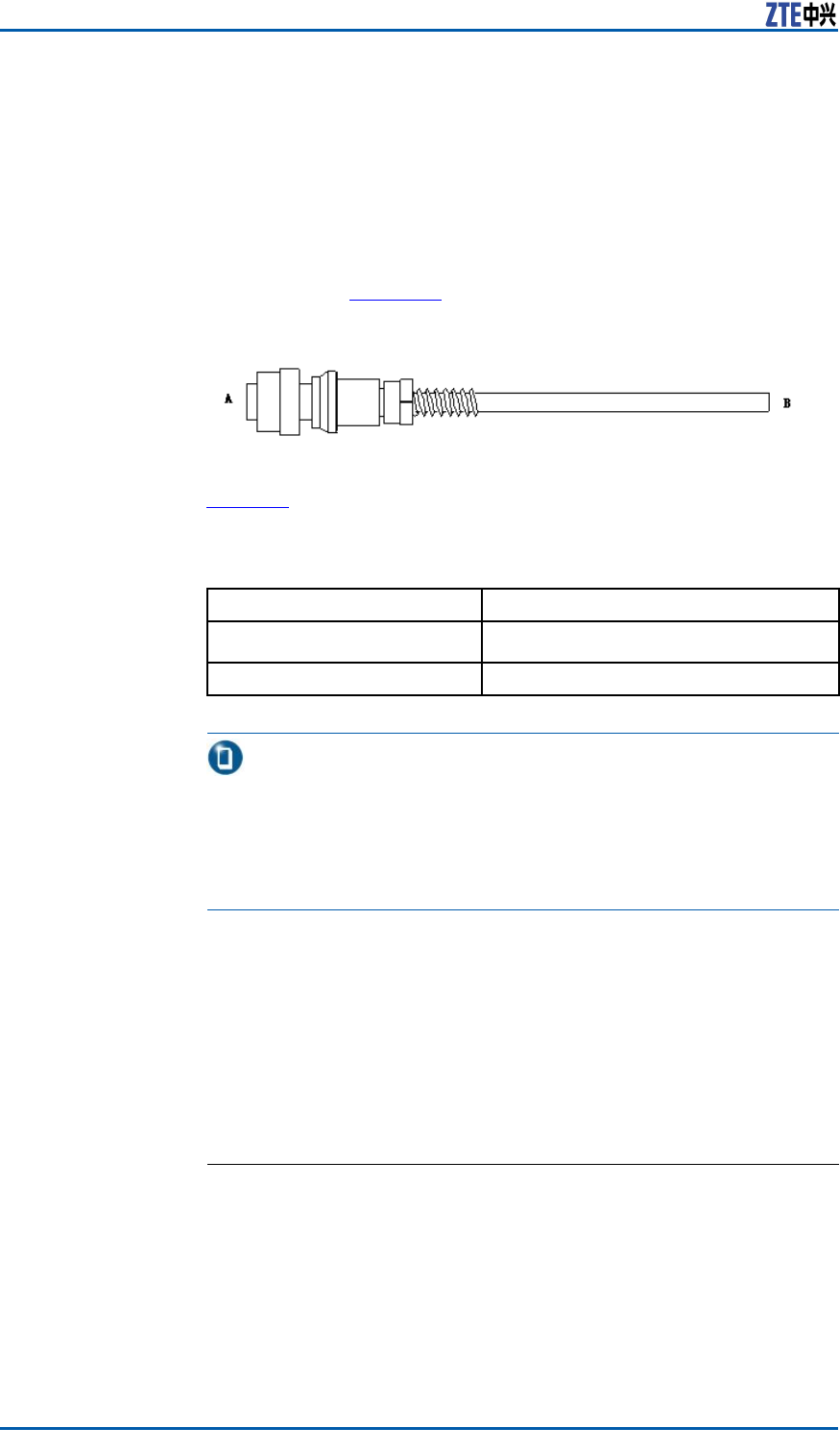
ContextTheZXSDRR8860cabinetadopts-48VDCforpowersupply.End
AistheaviationplugandEndBisreservedforself-madepower
cableonsite.Thelengthofpowercableisaccordingtotheengi-
neeringsurvey.
ZXSDRR8860Figure53showsthestructureofpowercable.
FIGURE53POWERCABLESTRUCTURE
Table13describesthecolorsandspecicationsofinsidecoreca-
ble.
TABLE13COLORANDSPECIFICATION
ColorSpecification
Blue-48V
Black-48VGND
Note:
1.Ifthetwo-corecableisadopted,thebluecorecablestands
for-48Vandtheblackcorecablestandsfor-48VGND;
2.Ifthefour-corecableisadopted,thetwobluecorecables
connectedinparallelstandfor-48Vandtheblackcorecables
connectedinparallelstandfor-48VGND.
Steps1.ConnectEndAofpowercablewithDCINinterfacelocatedat
thebottomofZXSDRR8860.
2.StriptheprotectivecoatofEndBandconnectitwiththeDC
inputpowersourceaccordingtocolorsoftheinsidecorecable.
3.MakewaterproofprotectionofEndB.
4.Attachlabelsatbothendsofthepowercable.
5.Fixthepowercable.
ENDOFSTEPS.
70ConfidentialandProprietaryInformationofZTECORPORATION
Chapter4ExternalCableInstallation
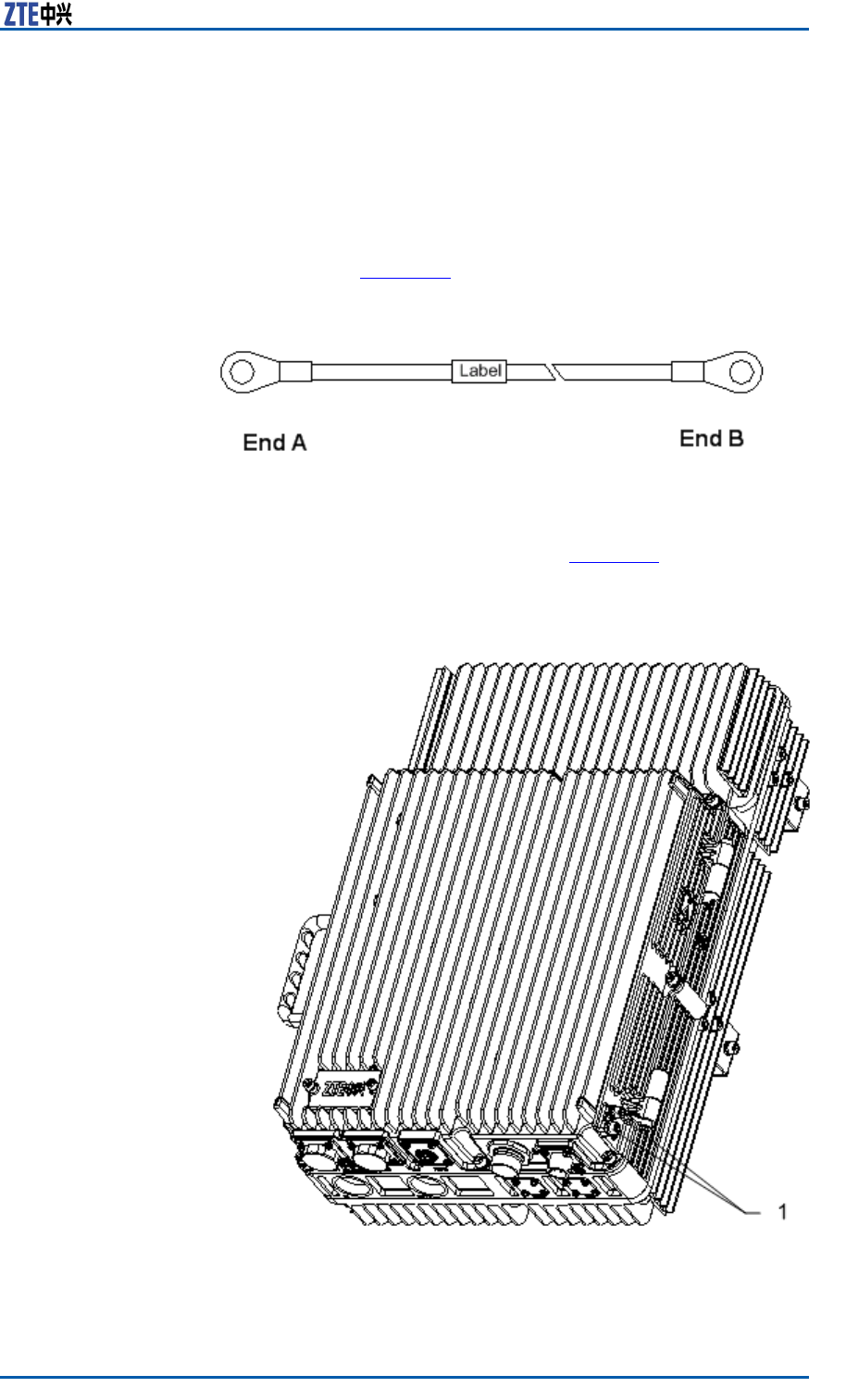
InstallingGroundingCable
ContextThegroundingcableismadeupofstrandsofame-retardantwire.
ThecrosssectionalareaofZXSDRR8860groundingcableis10
mm2.Thecolorofgroundingcableisyellowandgreen.Copper
lugsarecrimpedatbothendsoftheZXSDRR8860groundingca-
ble,asshowninFigure54.
FIGURE54GROUNDINGCABLESTRUCTURE
Steps1.Coverandxacopperlugontheagroundingboltofthe
ZXSDRR8860cabinet,asshowninFigure55.
FIGURE55ZXSDRR8860GROUNDINGBOLT
1.Groundingbolt
ConfidentialandProprietaryInformationofZTECORPORATION71
ZXSDRR8860InstallationManual
2.Connecttheothercopperlugtotheearth-networkingcopper
barandxitwithabolt,asshowninFigure56.
FIGURE56EARTH-NETWORKCOPPERBAR(UNIT:MM)
3.Attachthelabelonthegroundingcable.
4.Measurethegroundingresistanceandmakesureitlessthan
5Ω.
ENDOFSTEPS.
InstallingFiberbetween
BBUandRRU
PrerequisiteTheZXSDRR8860cabinetmustbeinstalledandxedsuccessfully.
ContextFigure57showsberconnectionbetweenZXSDRR8860andBBU.
FIGURE57FIBERCONNECTIONBETWEENZXSDRR8860ANDBBU
1.OutdoorSealComponent
WhileconnectingaBBUtoZXSDRR8860,makesurethatthebase-
bandRFberinterface(LC1/2)oftheZXSDRR8860isconnected
totheopticalinterfaceconnectoroftheBBU.
72ConfidentialandProprietaryInformationofZTECORPORATION
Chapter4ExternalCableInstallation
Steps1.Attachlabelsatbothendsoftheber .
2.AdjustthesideofEndAwiththecolormarkandinsertthe
ZXSDRR8860berinterface,andscrewdownthenuts,as
showninFigure58
FIGURE58OPTICALFIBERINSTALLATION
1.Colormark
3.ConnectEndAofthebertothebasebandRFberinterface
(LC1/2)oftheZXSDRR8860.
4.ConnectEndBoftheber ,whichisaDLCconnector ,tothe
BBUopticalconnector .
5.ScrewdowntheoutdoorsealcomponentatEndAforwater-
proong.
ENDOFSTEPS.
InstallingFiberbetween
RRUandRRU
PrerequisiteThecascadingZXSDRR8860cabinetsmustbeinstalledandxed
successfully.
ContextFigure59showsberconnectionbetweenZXSDRR8860s.
ConfidentialandProprietaryInformationofZTECORPORATION73
ZXSDRR8860InstallationManual
FIGURE59FIBERCONNECTIONBETWEENZXSDRR8860S
1.OutdoorSealComponent
WhileinterconnectingtheZXSDRR8860s,makesurethatthetwo
basebandRFberinterfaces(LC1/2)oftheZXSDRR8860arecon-
nected.
Steps1.Attachlabelsatbothendsoftheopticalber .
2.AdjustthesideofEndAwiththecolormarkandinsertthe
ZXSDRR8860berinterface,andscrewdownthenuts,as
showninFigure60.
FIGURE60OPTICALFIBERINSTALLATION
1.Colormark
3.ConnectEndAoftheopticalbertothebasebandRFber
interface(LC1/2)oftheZXSDRR8860.
4.ConnectEndBoftheopticalbertotheotherbasebandRF
berinterface(LC1/2)oftheZXSDRR8860.
74ConfidentialandProprietaryInformationofZTECORPORATION
Chapter4ExternalCableInstallation
5.ScrewdowntheoutdoorsealcomponentatEndAforwater-
proong.
ENDOFSTEPS.
InstallingEnvironment
MonitoringCable
PrerequisiteTheZXSDRR8860cabinetmustbeinstalledandxedsuccessfully.
ContextTheenvironmentmonitoringcableprovidesa485interface,used
forZXSDRR8860environmentmonitoring.Inaddition,theca-
blealsoprovidesfourextensionaccessesforexternaldrycontact
monitoring.
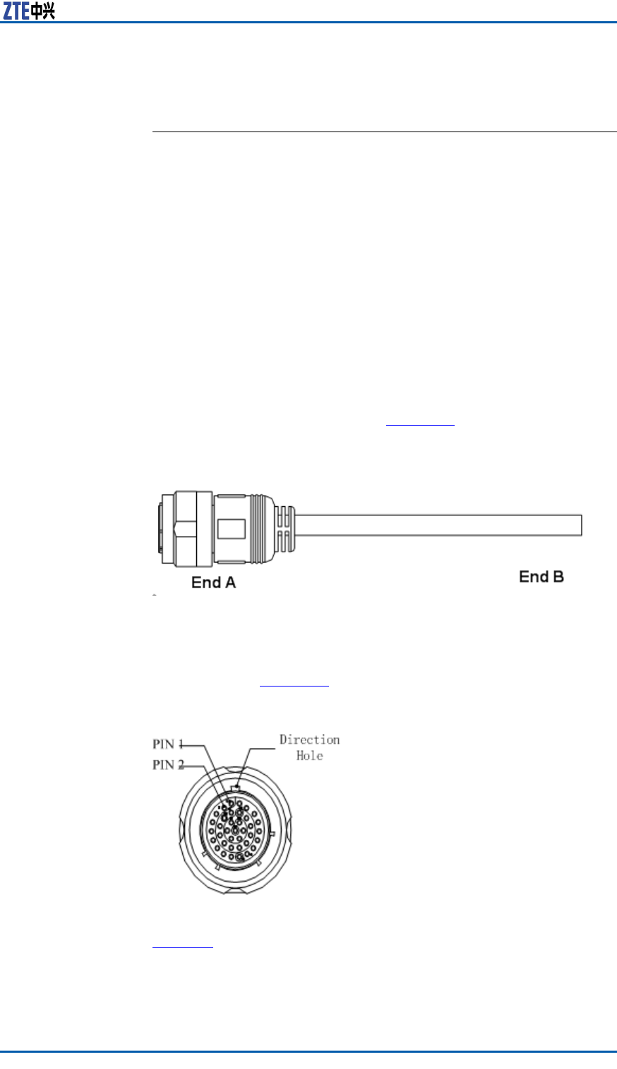
EndAisthe37PINconnector ,andEndBismadebyon-siteengi-
neering.Thetotallengthis3m.Figure61showstheappearance
ofenvironmentmonitoringcable.
FIGURE61ENVIRONMENTMONITORINGCABLE
Theconnector ,connectingtheenvironmentmonitoringcableto
theZXSDRR8860,adopts37–coreaviationjack.Theconnector
accordswiththeGJB599specication.Theconnectorappearance
isasshowninFigure62
FIGURE62AVIATIONJACKAPPEARANCE
Table14describestheconnectorpins.
ConfidentialandProprietaryInformationofZTECORPORATION75
ZXSDRR8860InstallationManual
TABLE14CABLEPINDESCRIPTION
PinCore-CableColorSignalDescription
15/16Whiteandblue/blueDrycontact4-/+
17/18Whiteand
orange/orange
Drycontact3-/+
19/20Whiteand
green/green
Drycontact2-/+
21/22Whiteand
brown/brown
Drycontact1-/+
23/24Redandblue/blueRS485receive
25/26Redandorange/ora
nge
RS485transmit
Steps1.ConnectEndAtotheMONinterfacelocatedatthebottomof
ZXSDRR8860.
2.ConnectEndBwithexternalmonitoringdevicesordrycon-
tacts.
3.AttachthelabelatEndB.
ENDOFSTEPS.
InstallingAISGControl
Cable
ContextTheAISGcontrolcableisusedforcontroloftheelectricaladjust-
mentantenna.
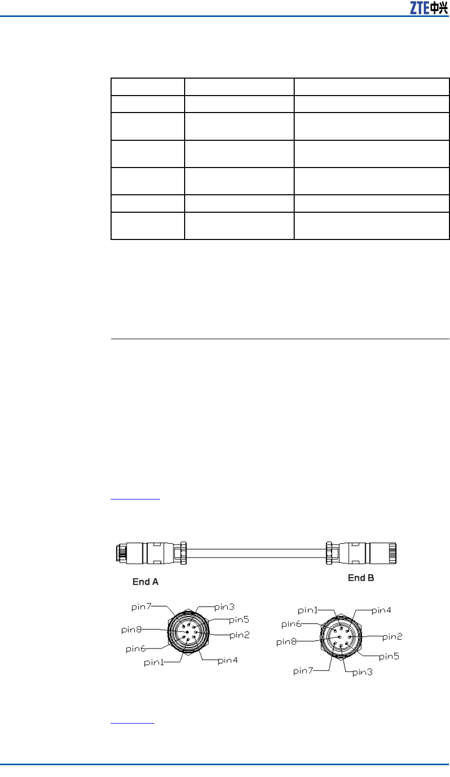
Figure63showsthestructureoftheAISGcontrolcable.
FIGURE63AISGCONTROLCABLESTRUCTURE
Table15describestheserialNo.meaningofAISGcontrolcable.
76ConfidentialandProprietaryInformationofZTECORPORATION

Chapter4ExternalCableInstallation
TABLE15AISGCONTROLCABLEDESCRIPTION
SerialNo.NameMeaning
1TRX_ANT_485_+RS485+
2TRX_ANT_485_-RS485-
3,4TRX_ANT_28V28V
5,6TRX_ANT_28VGND28VGND
7,8NCNull
Steps1.ConnectEndAtotheZXSDRR8860debugginginterface
(AISG)andscrewdownthebolt;
2.ConnectEndBtothecontrolinterfaceofelectricaladjustment
antennaandscrewdownthebolt.
ENDOFSTEPS.
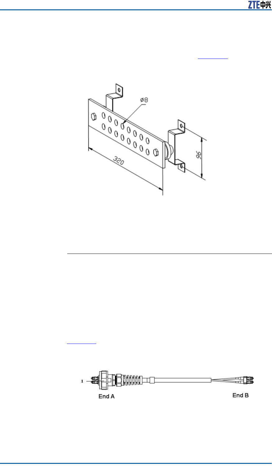
InstallingFrequencyPoint
ExtensionCable
PrerequisiteThetwoZXSDRR8860cabinetstobecombinedmustbeinstalled
andxedsuccessfully.
ContextAfterthecombinationofcabinets,theZXSDRR8860cansupport
8carriersectorsatmost.
ThetwoZXSDRR8860cabinetsareconnectedthroughtheircon-
nectinginterfacessuchasRXinandRXoutbytwofrequencypoint
extensioncables.Figure64showsthestructureofthefrequency
pointcable.EndAandEndBareNconnectors(male).
The2M1/2″jumperisoftenusedforthefrequencypointextension
cable.Itmaybepreparedonsiteifnecessary.
FIGURE64FREQUENCYPOINTEXTENSIONCABLE
Steps1.ConnectEndAofthefrequencypointextensioncabletothe
frequencypointextensioninterfaceRXINofoneZXSDRR8860;
2.ConnectEndBtoRXoutoftheotherZXSDRR8860;
ConfidentialandProprietaryInformationofZTECORPORATION77
ZXSDRR8860InstallationManual
3.ConnecttheremainingRXin/RXoutinterfacesofthetwocom-
binedcabinetswiththeotherfrequencypointextensioncable.
ENDOFSTEPS.
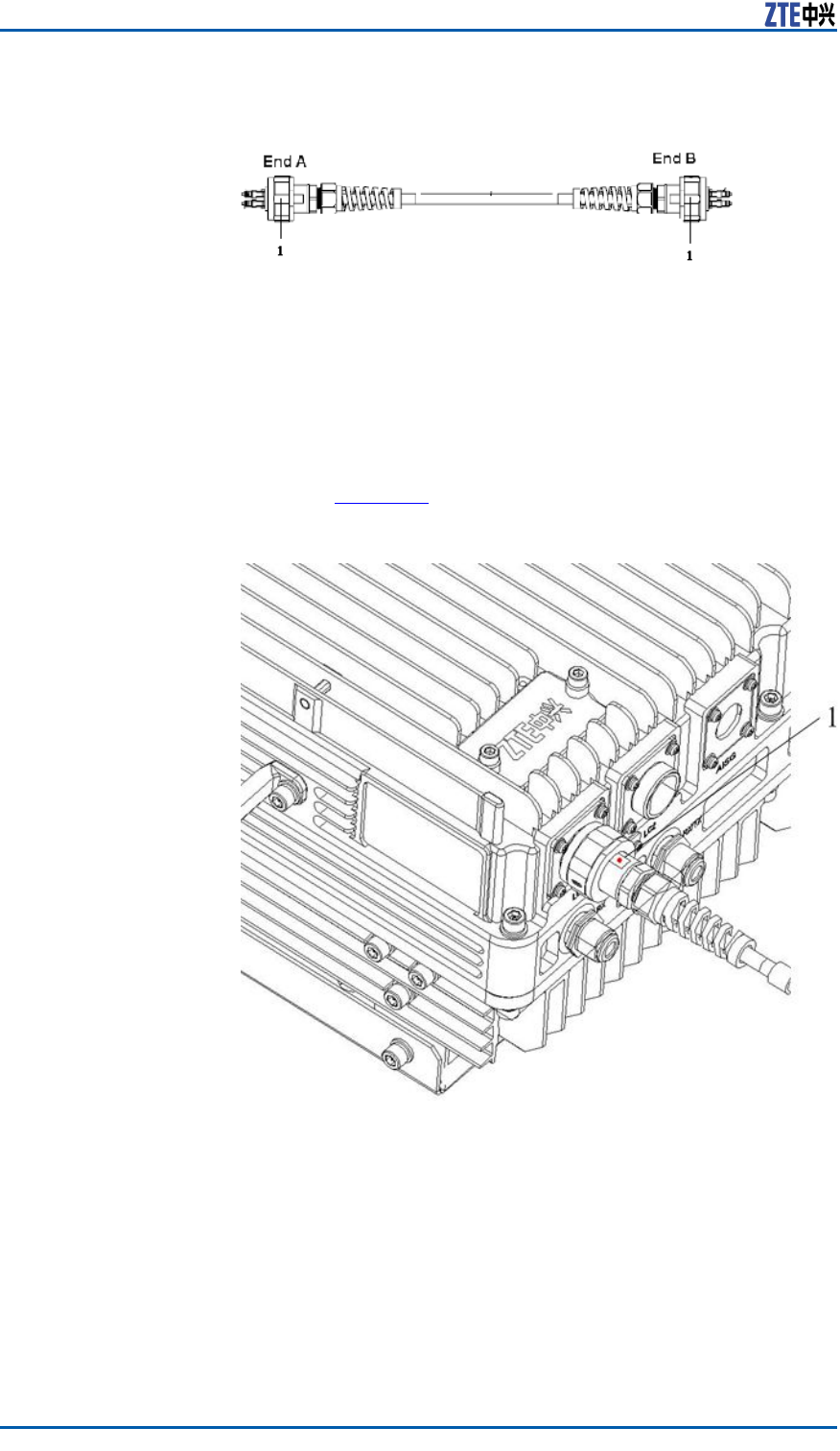
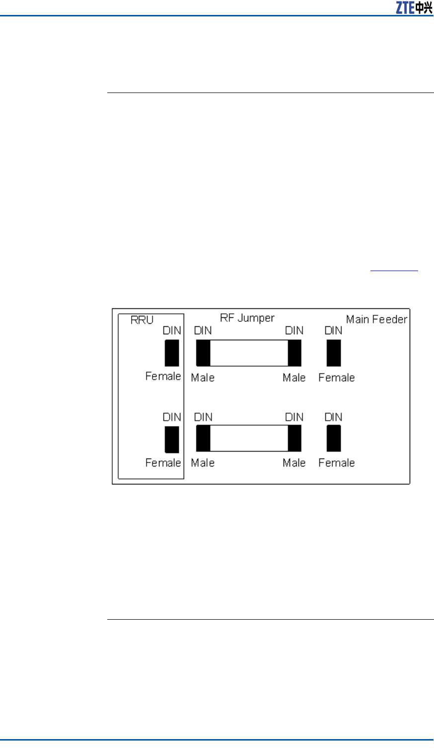
InstallingJumper
ContextOneendofRFjumperconnectswiththemainfeederandtheother
endconnectswiththeantennafeederinterfaceofZXSDRR8860
cabinet.BeforeinstallingtheRFjumper ,themainfeederisin-
stalled.
TheRFjumperadoptsthe1/2″jumperwitha2mlength.The
jumpercanalsobeself-madeaccordingtotheon-sitecondition.
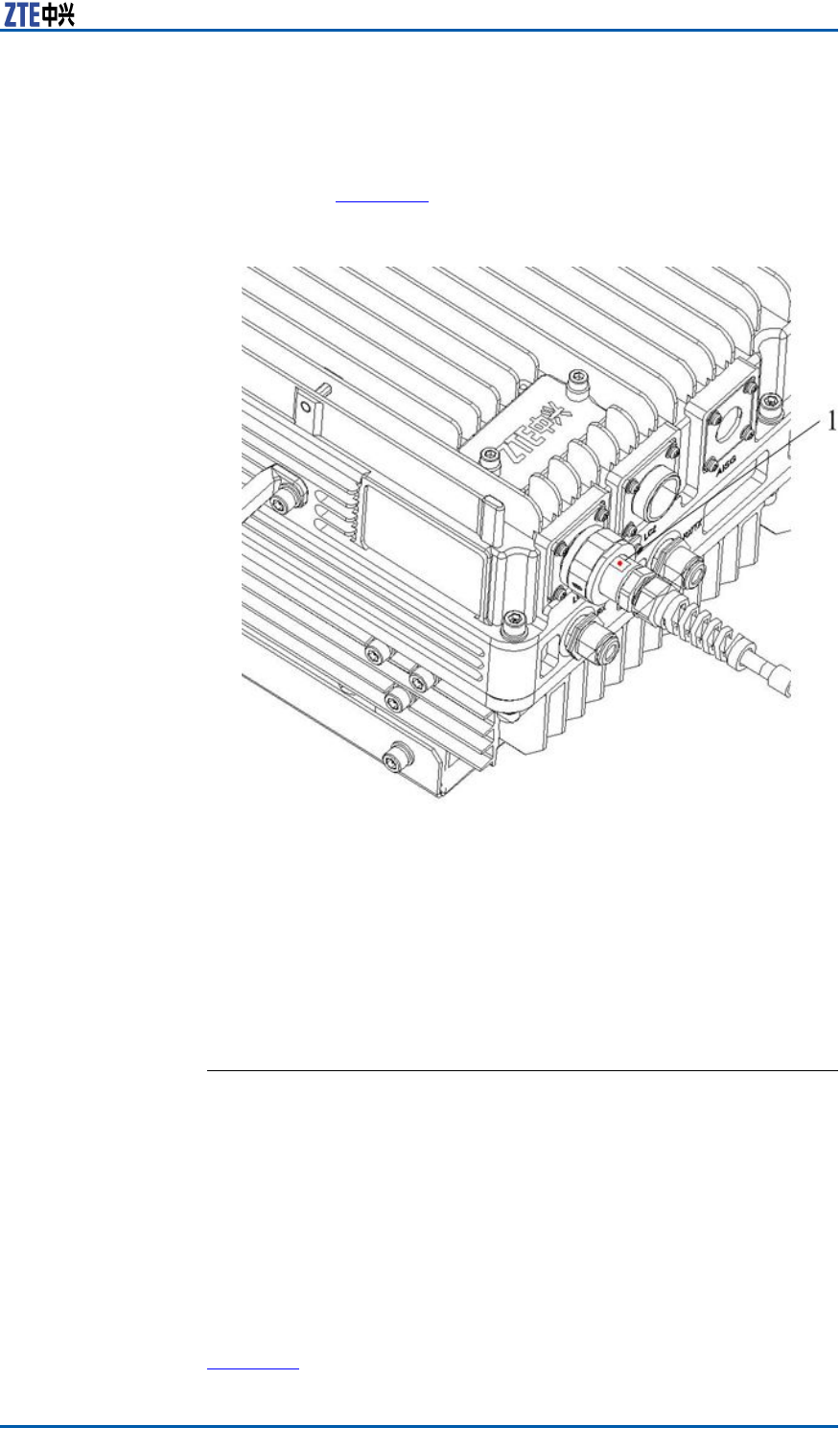
TheinstallationpositionofRFjumperisasshowninFigure65.
FIGURE65RFJUMPERINSTALLATION
PerformthefollowingstepstoinstalltheRFjumper .
Steps1.ConnecttheDINconnector(male)ofRFjumperwiththeDIN
connector(female)ofmainfeeder .
2.ConnecttheDINconnector(male)ofRFjumperwiththeDIN
connector(female)ofZXSDRR8860cabinet.
3.SealtheconnectorswithwaterproofadhesivetapesandPVC
tapes.
ENDOFSTEPS.
78ConfidentialandProprietaryInformationofZTECORPORATION

Chapter5
MainAntennaFeeder
SystemInstallation
TableofContents:
MainAntennaFeederSystemStructure................................79
MainAntennaFeederSystemInstallationPreparation.............85
MainAntennaFeederSystemInstallationFlow......................86
AntennaInstallation...........................................................87
FeederInstallation.............................................................92
InstallingFeederHermetic-window....................................102
FeederIndoorIngoing......................................................104
PerformingAntennaFeederSystemTest.............................108
PerformingOutdoor-connectorWaterproofProcessing...........109
PerformingFeederHermetic-windowWaterproofProcess-
ing................................................................................111
CabinetJumperInstallationDescription..............................114
VSWRT est......................................................................115
MainAntennaFeeder
SystemStructure
ThetypicalcongurationsforZXSDRR8860mainantennafeeder
systemdescribedbelowincludes:
�ZXSDRR8860congurationwithcommonantenna
�ZXSDRR8860congurationwithcommonantenna,AISGdual
poweramplier
�ZXSDRR8860congurationwithelectronicadjustmentan-
tenna(1)
�ZXSDRR8860congurationwithelectronicadjustmentan-
tenna(2)
�ZXSDRR8860congurationwithelectronicadjustmentan-
tenna,AISGdualpoweramplier
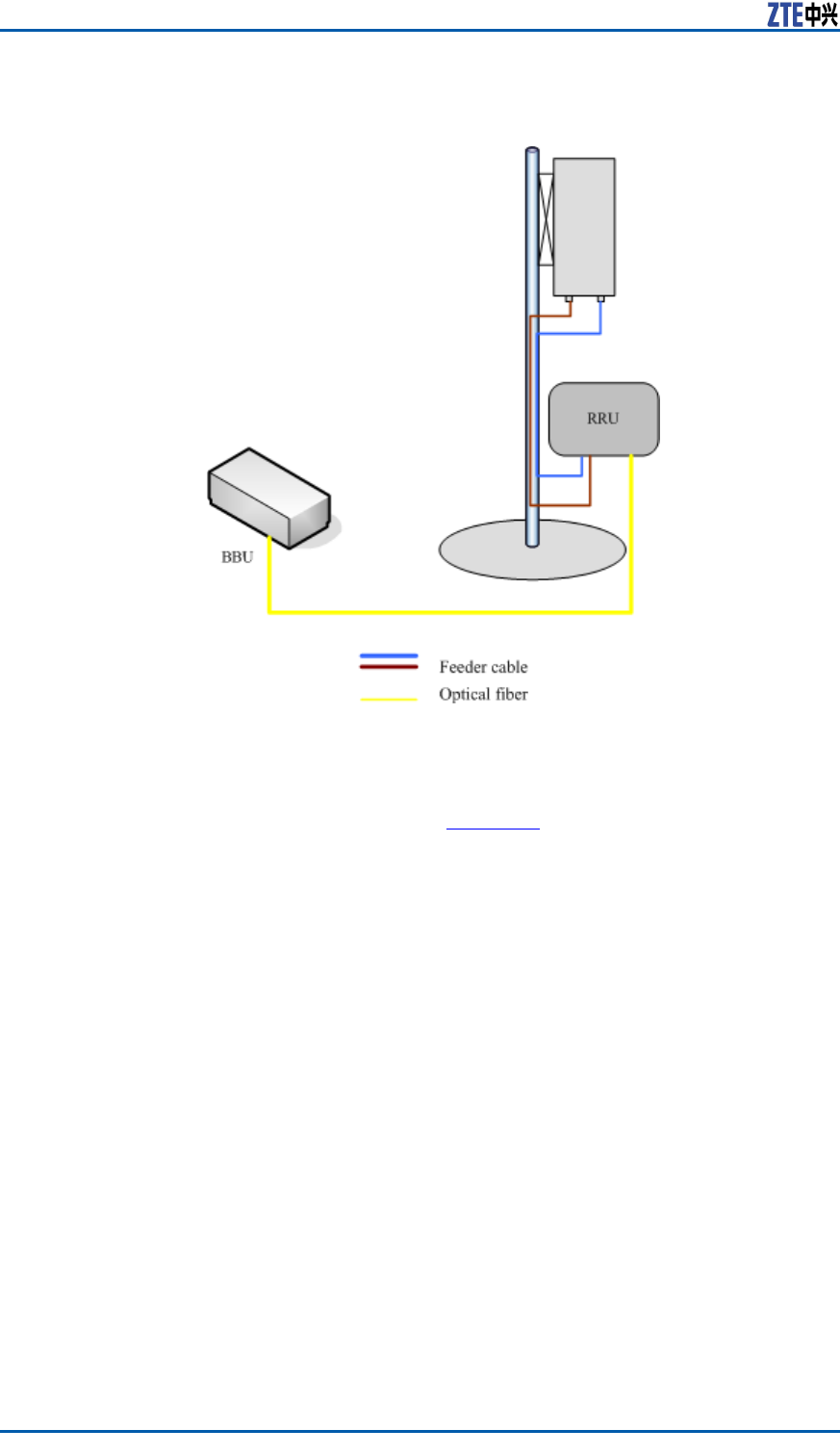
ZXSDRR8860
congurationwith
commonantenna
Inthisconguration,generallyZXSDRR8860installationposition
isnearantennaandtheyareallinstalledonthebuildingtop.
ZXSDRR8860isconnectedtotheantennaby1/2″feederdirectly,
occasionally5/4″or7/8″feederisadopted,asshowninFigure66.
ConfidentialandProprietaryInformationofZTECORPORATION79
ZXSDRR8860InstallationManual
FIGURE66ZXSDRR8860CONFIGUREDWITHCOMMONANTENNA
.
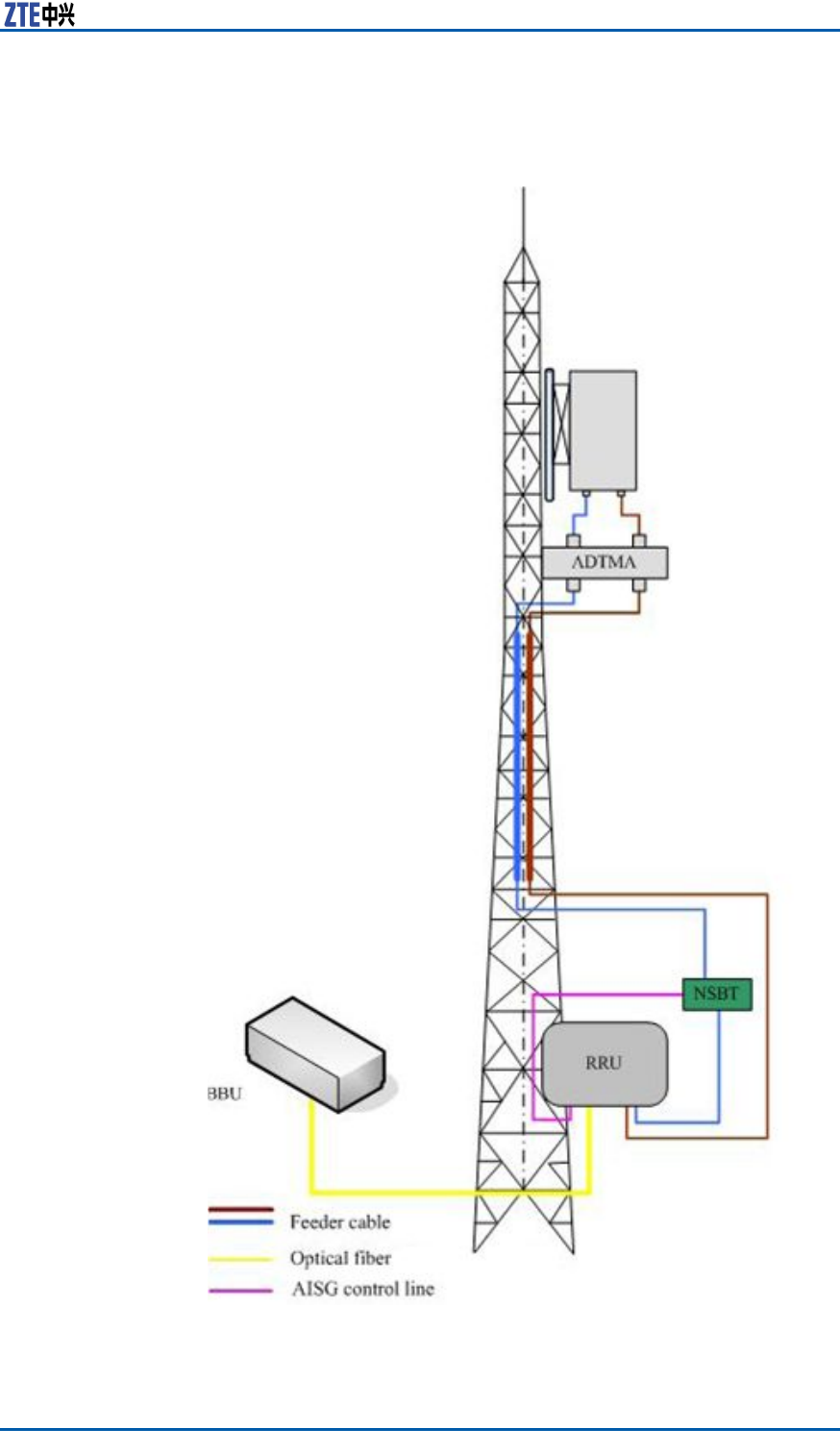
ZXSDRR8860
congurationwith
commonantenna,
Inthisconguration,generallyZXSDRR8860isinstalledonthe
tower .ZXSDRR8860isconnectedtotheantennaby5/4″or
7/8″feeder ,asshowninFigure67.
80ConfidentialandProprietaryInformationofZTECORPORATION
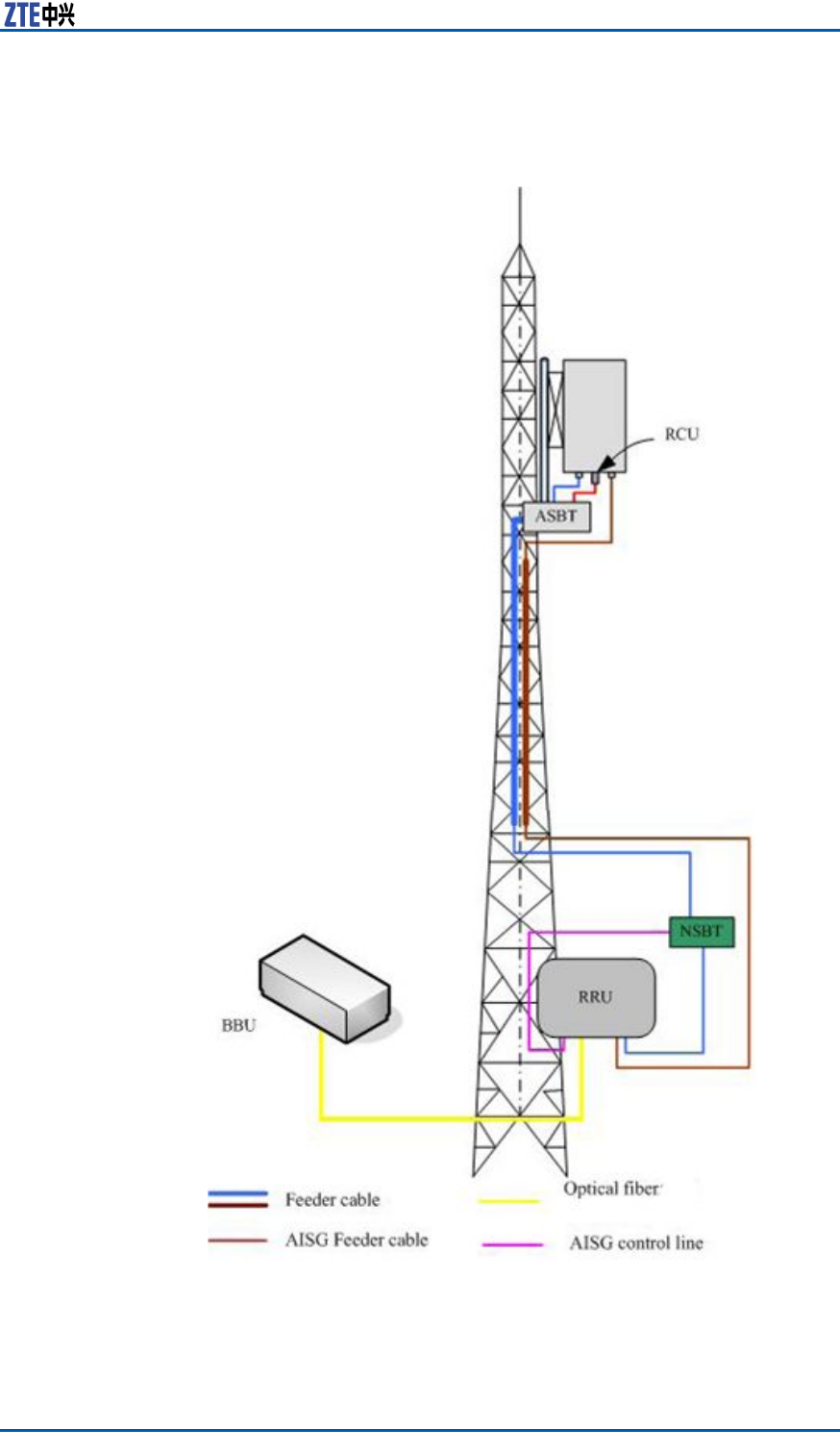
Chapter5MainAntennaFeederSystemInstallation
AISGdualpower
amplierFIGURE67ZXSDRR8860CONFIGURATIONWITHCOMMONANTENNA,
AISGDUALPOWERAMPLIFIER
ConfidentialandProprietaryInformationofZTECORPORATION81
ZXSDRR8860InstallationManual
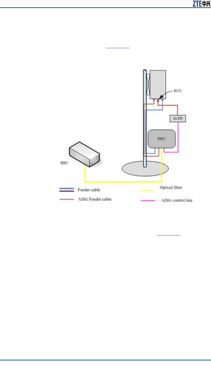
ZXSDRR8860
conguration
withelectronic
adjustment
antenna(1)
Inthisconguration,generallyZXSDRR8860installednearthe
antennaonthebuildingtop.ZXSDRR8860isconnectedtothe
antennaby1/2″feederdirectly,occasionally5/4″or7/8″feederis
adopted,asshowninFigure68.
FIGURE68ZXSDRR8860CONFIGURATIONWITHELECTRONIC
ADJUSTMENTANTENNA(1)
ZXSDRR8860
conguration
withelectronic
Inthisconguration,generallyZXSDRR8860isinstallednearthe
topofthetower .ZXSDRR8860isconnectedtotheantennaby
5/4″or7/8″feederisadopted,asshowninFigure69.
82ConfidentialandProprietaryInformationofZTECORPORATION
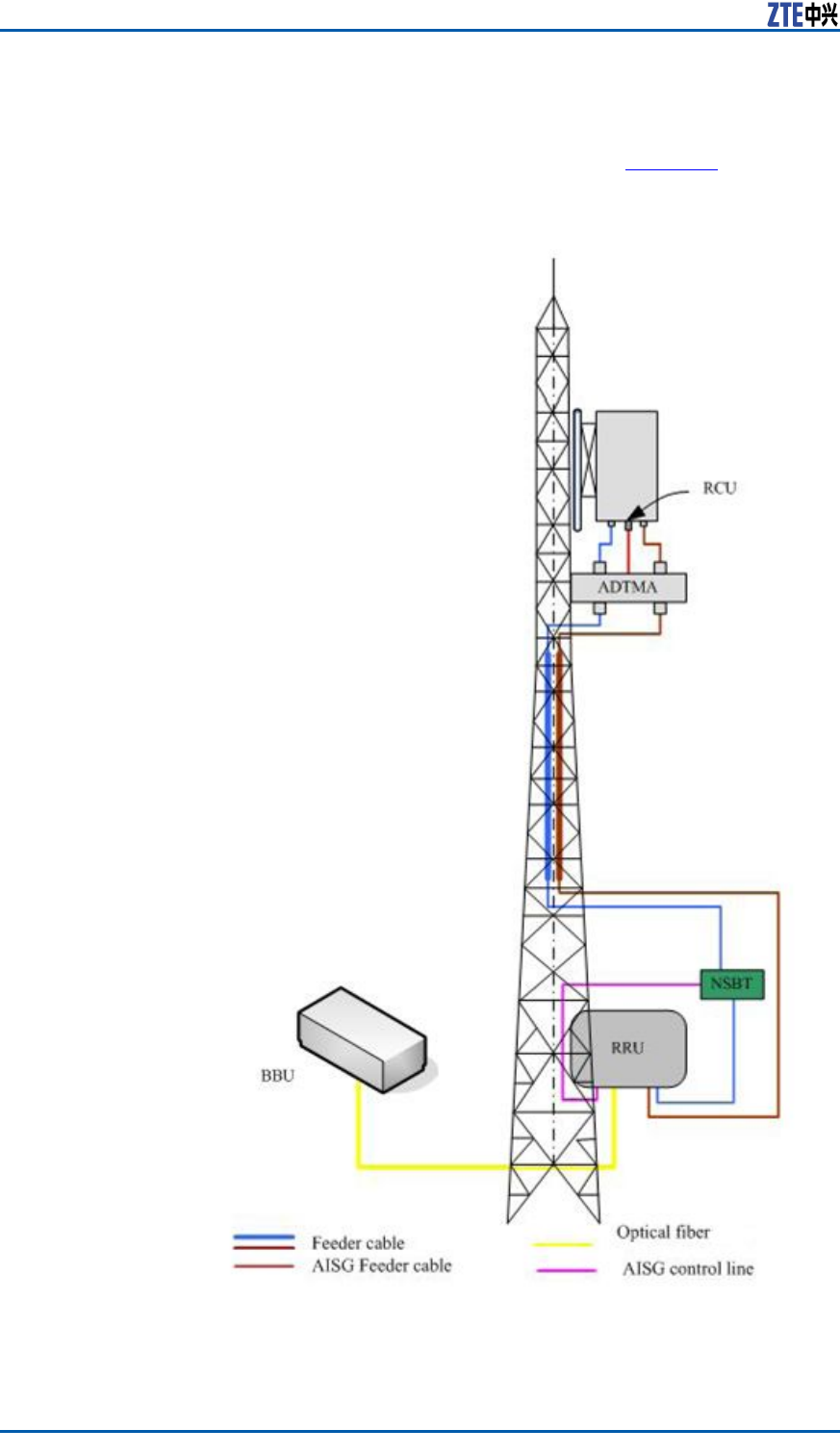
Chapter5MainAntennaFeederSystemInstallation
adjustment
antenna(2)FIGURE69ZXSDRR8860CONFIGURATIONWITHELECTRONIC
ADJUSTMENTANTENNA(2)
ConfidentialandProprietaryInformationofZTECORPORATION83
ZXSDRR8860InstallationManual
ZXSDRR8860
conguration
withelectronic
adjustment
antenna,AISG
dualpower
amplier
Inthisconguration,generallyZXSDRR8860isinstallednearthe
topofthetower .ZXSDRR8860isconnectedtotheantennaby
5/4″or7/8″feederisadopted,asshowninFigure70.
FIGURE70ZXSDRR8860CONFIGURATIONWITHELECTRONIC
ADJUSTMENTANTENNA.AISGDUALPOWERAMPLIFIER
84ConfidentialandProprietaryInformationofZTECORPORATION

Chapter5MainAntennaFeederSystemInstallation
MainAntennaFeeder
SystemInstallation
Preparation
ProperantennainstallationisveryimportanttoZXSDRR8860sys-
temreliableoperation.Beforeinstallation,makesurethatinstalla-
tionstaffisqualiedandthefollowingrequirementsaresatised.
Personnel
Requirement
Normally,supervisorsareinchargeofdirectionandsupervision,
whereasinstallationpersonnelcarryouttheinstallation.
�InstallationSupervisor
Therequirementsfortheinstallationsupervisorareasfollows:
�Familiarwithallmaterials,toolsandoperationmethods.
�Theyareinchargeofassigningdifferentworktotheproper
employeewhoisgoodattheoperation,especiallywhile
workingontheirontower .
Note:
Safetyisthemostimportantconsiderationwhenassigning
work.
�InstallationPersonnel
Therequirementsfortheinstallationpersonnelareasfollows:
�Installationemployeesarerequiredtoinstallantennasys-
temskillfullyunderthedirectionofsupervisor .
�Employeesontowermustbequaliedandingoodphysical
state.
�Installationafterdrinkingisforbidden.
Environment
Requirement
Payattentiontofollowingitemsandcheckwhethertheysatisfy
requirementsinengineeringdesign.Normally,theyarecompleted
bythenetworkoperator(carrier).
�Lightningprotectionandgrounding
ZXSDRR8860isusuallylocatedoutdoors.Thegrounding
stakeandoutdoorlightning-protectinggroundingcablesare
installedbytheoperator ,andthesupervisorshouldconrm
lightning-protectinggroundingcablesareinstalledproperly.
�Poleandsupportingrack
Accomplishinstallationofantennasupportingrackandpole
accordingtoprojectdesignrequirement.Thestabilityofthe
supportingrackandpoleshouldbeinaccordancewiththede-
signrequirement.
�Feederlayout
Fieldengineersneedtodeterminerouteofmainfeederwith
operatorengineersbeforeinstallation.
ConfidentialandProprietaryInformationofZTECORPORATION85

ZXSDRR8860InstallationManual
�Electronicpowerenvironment
�ZXSDRR8860antennaandfeedersystemcannotbeinstalled
tooneartopublicelectricpowercables.
Safety
Precautions
Ensurethefollowingprecautionsbeforeantennainstallation:
�Takenecessarymeasuresforpersonalandequipmentsafety.
�Personnelundertowermustwearsafetyhelmets.
�Personnelontowermustwearsafetybelt.
�Neverclimbtowerwithlooseclothesandwet/slipperyshoes.
�Duringactiveantennaadjustment,wearradiation-shielding
clothingandturnoffpowerampliertoavoidradiationeffects.
�Ifpossible,installinsunnyandwindlessdays.Installationis
forbiddeninrain,strongwind,thunderandlightning.
�Makecautionbrandinengineeringeldandkeeppassengers
awayfromengineeringeld,especiallykids.
�Whenworkingontower ,putunusedtoolsinatoolbagand
preventthemfromdroppingdownfromtowertohurtpeople.
ToolsRequire-
ment
Thefollowingtoolsarerequiredformainantennafeedersystem
installation:
�Measuretools
Compass,multimeter ,anglemeter ,andtapemeasure
�Specialtools
Mainfeederconnectormanufacturing,specialtoolsandinstru-
mentsfortest
�Regulartools
Adjustablewrench,sharp-nosepliers,diagonalpliers,hacksaw
(withseveralsawblades)
�Protectiontools
Safetyhelmet,safetybelt,safetyrope,gloves,radia-
tion-shieldingclothes,multiplepowersocketandsealed
canvastoolbag
�Othertools
Toolsforlifting,e.g.Ladder
MainAntennaFeeder
SystemInstallationFlow
Figure71showstheinstallationowofmainantennafeedersys-
tem.
86ConfidentialandProprietaryInformationofZTECORPORATION
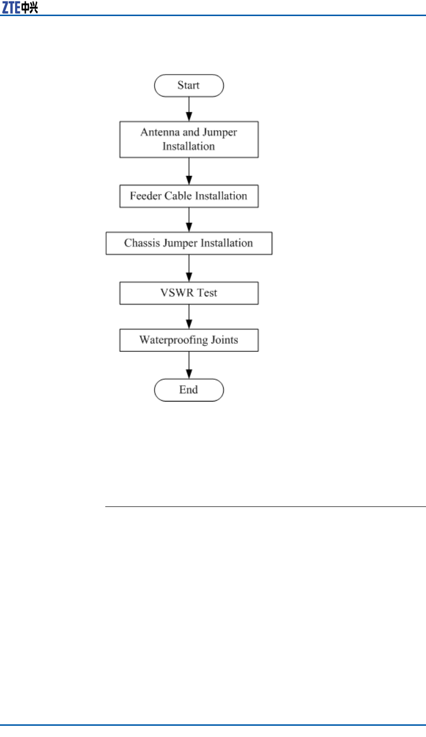
Chapter5MainAntennaFeederSystemInstallation
FIGURE71MAINANTENNAFEEDERSYSTEMINSTALLATIONFLOW
AntennaInstallation
AntennaInstallationTechnical
Specifications
Theantennatechnicalspecicationsandtheirdescriptionisgiven
below.
�Antennaheight
Theinstallationheightofantennaisdeterminedbynetwork
planningdesign.
�Antennaazimuth
Theazimuthoftheantennaisdeterminedbynetworkplanning
design.
�Antennadowntilt
Thedowntiltangleoftheantennaisdeterminedbynetwork
planningdesign.Usuallythedowntiltangleis0°~10°
�Antennadirection
ConfidentialandProprietaryInformationofZTECORPORATION87
ZXSDRR8860InstallationManual
Antennadirectiondependsontheantennaazimuth.Iftwo
antennasinonesector ,mustsharethesameazimuth.
AntennaInstallationPosition
Theantennainstallationpositionmustbeinaccordancewith
projectdesign.Iftheinstallationpositionneedsanymodication,
theprojectsupervisormustnegotiatewithoperator’srepresen-
tative.
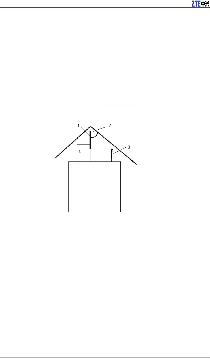
Theantennainstallationpositionneedstotakecareforelightning
protectionasshowninFigure72.
FIGURE72ANTENNAINSTALLATIONPOSITION
1.Lightningrod
2.45°Lightningprotectionarea
3.Antenna
4.Groundingcable
Followingarelightningprotectionrequirementstoinstallanan-
tenna:
�Theantennashouldbeinstalledwithin45°coverageareaof
lightningrod.
�Ifthereisnospeciallightningprotectionarrangementlikethe
above,installthelightningprotectionsystemontotheantenna
pole.
�Makesurethatthelightningrodiswellgrounded.
DirectionalAntennaInstallation
ContextThedirectionalantennainstallationprocedureisgivenbelow.
88ConfidentialandProprietaryInformationofZTECORPORATION
Chapter5MainAntennaFeederSystemInstallation
Note:
Thefollowingstepsdescribetheinstallationprocessasareference
forinstallationpersonnel.Duringtheon-siteinstallationprocess,
pleasecarefullyreadtheinstallationmanualprovidedwiththean-
tenna,andcarryouttheinstallationaccordingtotheactualcon-
dition.
Performthefollowingstepstoinstalladirectionalantenna:
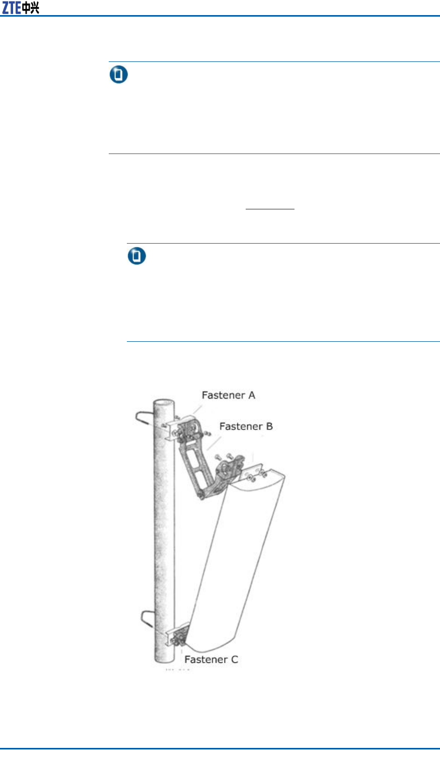
Steps1.Firstlyassemblefastener"C"ontotheupperandlowerends
ofantennaasshowinFigure73,thenconnectfasteners"B"
and"A"tocompletetheinitialinstallationofthedirectional
antenna.
Note:
�Allaccessoriesmustbeinstalledwithspringandplain
washers.
�Usuallytheantennafasteningaccessoriesandtheangle
adjustmentdeviceaccessorieshavealreadybeeninstalled
ontheantennabeforexingintothetower .
FIGURE73DIRECTIONALANTENNAINSTALLATION
ConfidentialandProprietaryInformationofZTECORPORATION89
ZXSDRR8860InstallationManual
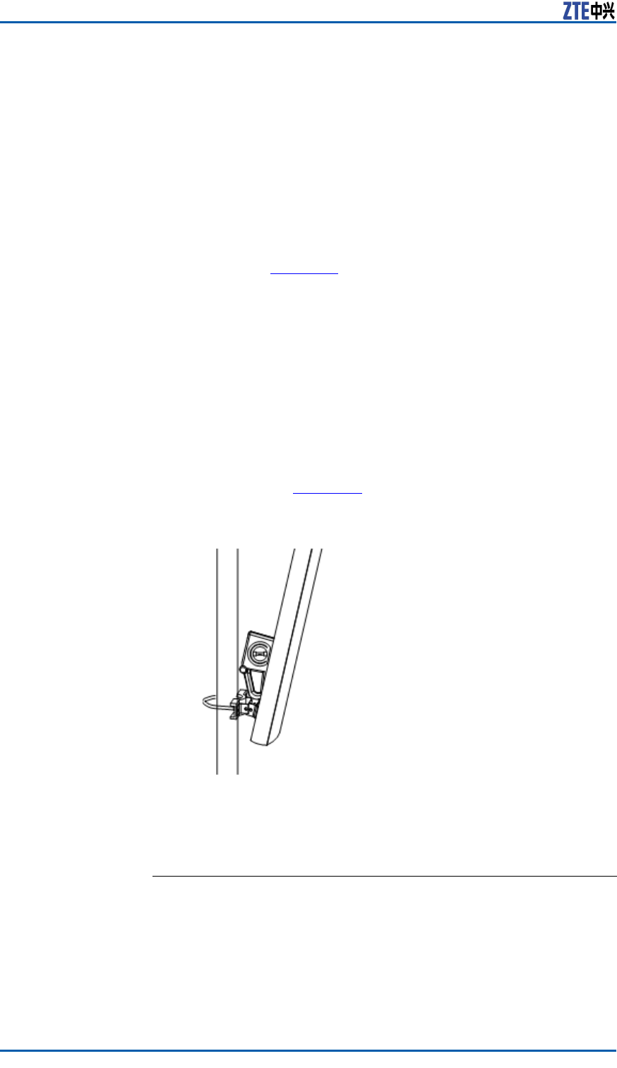
2.Attachtheantennaalongwithxturesontothepole.Donot
tightenthescrewstootightlytoalloweasyadjustmentofthe
directionanddowntiltoftheantenna.However ,degreeof
tightnessmustbehighenoughtoensurethattheantennadoes
notsliddownward.
3.Adjusttheantenna’sazimuth.
i.Determinetheazimuthoftheantennabyusingacompass,
anddeterminetheinstallationdirectionaccordingtothe
engineeringdesigndrawing.
ii.Turntheantennaslightlytoadjustit’sfacedirectionas
showninFigure73.Atthesametime,measurethedirec-
tionoftheantennawithacompassuntiltheerrorcomes
withintheengineeringdesignrequirements(generallynot
morethan5°).
iii.Afteradjustingtheazimuthoftheantenna,tightenthefas-
tener"A".
4.Adjusttheantenna’sdowntilt
i.Adjustthedowntiltofthemeasurementmetertoobtain
therequiredangleaccordingtotheengineeringdesign.
ii.Turnthetopoftheantennaslightly,andlooseorfastthe
antennaatitstop.Adjustthedowntiltangleoftheantenna
tillthemeasurementmeter’sbubblecomestobecentered
asshowninFigure74.
FIGURE74ANTENNADOWNTILTADJUSTMENT
iii.Afteradjustingthedowntiltoftheantenna,tightenthefas-
tener"B.
ENDOFSTEPS.
ResultThedirectionalantennaisinstalled.
90ConfidentialandProprietaryInformationofZTECORPORATION
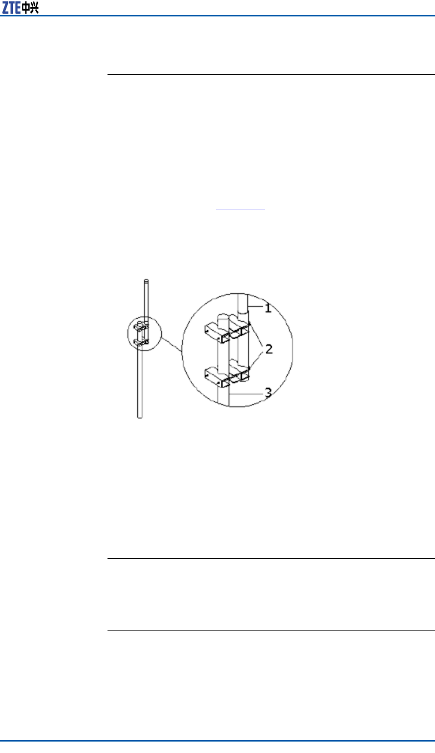
Chapter5MainAntennaFeederSystemInstallation
OmniAntennaInstallation
ContextPerformfollowingstepstoinstallanOmnidirectionalantenna:
Steps1.Determinetheinstallationposition.
2.Sealtheantenna’slowerpart(jumper)withthejacketand
placetheantennaasmuchclosetothesupportingpole.
3.Ensurethatthetopofthejacketslightlyhigherthanthetop
ofsupportingpole.
4.Fastentheantennaontothesupportingpolewithtwoxing
clipsasshowninFigure75.Donotfastentheclipswhether
tootightlyorloosely.Iffastenedtootightly,thejacketmaybe
damaged;iffastentooloosely,theweight-bearingandwind-
resistancerequirementscannotbemet.
FIGURE75OMNIDIRECTIONALANTENNAINSTALLATION
1.Antenna
2.Fixingclips
3.Antennapole
5.Measuretheverticalityoftheantenna,andensurethatan-
tennaisvertical.
6.Afterensuringtheverticalitytightenthexingclipsrmly.
7.Aftertheantennaisinstalledontothesupport,xtheantenna
supportontothetower .
ENDOFSTEPS.
ResultTheOmnidirectionalantennaisinstalled.
ConnectJumperandAntenna
ContextPerformthefollowingstepstoconnectjumperwithantenna.
ConfidentialandProprietaryInformationofZTECORPORATION91

ZXSDRR8860InstallationManual
Note:
Theantennajumpercanbeconnectedbeforetheantenna
mountedontothepole,andneededtotakethewaterproof
measurements.Thishighlyreducestheworktime,providegood
connection,andimproveswaterpreventionquality.
Steps1.Connectthejumperconnectortotheantennaport,andtighten
itproperly.
2.Sealthejumperconnectorandantennaportforwaterproof
treatment.
i.Wrapthewaterproofadhesivetapeslowersideofconnec-
tors.Keepwrappingdirectionsameastheonethatthe
jumperistightened.
ii.Whilewrapping,extendtheadhesivetapestodoubletheir
length.Notethateverywrappinglayermustbeoverlapped
thepreviouslayerbyhalfthewidthofthetapeWrap-
pingmustbeextendedupto50mm(2inches)awayfrom
jumperconnectorposition.
iii.Gripthetapewithyourhandstomakethetapetightly
adhered.
iv.WrapPVCtapesontopofthewaterproofadhesivetape.
Duringtheprocess,makesuretheupperlayeroverlaps
thelowerlayerbyhalfthewidthofthetape.
ENDOFSTEPS.
ResultThejumperisconnectedwithantenna.
FeederInstallation
FeederCuttingPrinciple
Determinelengthofthefeederaccordingtonalfeederroute,and
cutthefeedersaccordingtothelengthrequiredofeachfeeder .
Note:
Ifthefeederlengthislessthan10meters,use1/2”feeder;ifthe
feederlengthis10~30meters,use7/8”feederandifthefeeder
lengthismorethan30meters,use5/4”feeder .
Followingarethetypicalfeedercuttingscenarioobservedon-site:
�Iftheantennafeedersystemistobeinstalledonthe
buildingroof
92ConfidentialandProprietaryInformationofZTECORPORATION

Chapter5MainAntennaFeederSystemInstallation
1.Measurethelengthofmainfeederforeachsectoraccordingto
thenalfeederroute.
2.Addanappropriatemargin(1m(3.3feet)~2m(6.6feet))
tothemeasuredlengthswhencuttingthefeeders.
3.Aftercuttingonemainfeeder ,attachthetemporarylabelsat
bothendsofthefeeder ,suchasANT0andANT2.Attachthe
formallabelstothefeederafteritisinstalled.
4.Carrythecutfeederstotheroofofthebuilding,andmakesure
theyarenotsqueezedordamagedduringtheprocess.
�Iftheantennafeedersystemistobeinstalledonaniron
tower
1.Hoistoneendofthefeedertothetopofthetowerbyusinga
pulleyblockandpullingrope.Beforehoisting,maketheupper
mainfeederconnector .
2.Thepersonnelonthetowermustcutthefeederaccordingto
thedistancefromthepointwherethefeederenterstheroom
tothelightningarresterrack,withanappropriatemarginre-
served.Makeatemporarylabelforthelowerpart.Attachthe
formallabelstothefeederafteritisinstalled.
Caution:
Attheendoffeedercuttingprocess,attachlabelatbothends.
Temporarylabelscanalsobeattachedtothemiddleofthefeeder
duringthefeedercuttingprocess.Makesurethatalllabelsare
consistentwiththeactualsituation.Otherwise,thefeedermay
notbeconnectedcorrectlyandthesectorsmaynotcorrespondto
thefeeder .
FeederInstallationonTopofBuilding
PrerequisiteThesupportingpoleandantennaisinstalled.
ContextPerformthefollowingstepstoinstallthemainfeederontopof
building:
Steps1.Firstlydeterminethenalmainfeederroute.
2.Cutthemainfeederaccordingtothedeterminedlengthonthe
nalroute.
3.Arrangethemainfeederingoodorderwithoutcrossing.
4.Preparetheconnectorsandjumpers.
5.Laythefeedersaccordingtothelayingprinciple.
6.Laythemainfeederalongtothesupportingpoleasshownin
Figure76.
ConfidentialandProprietaryInformationofZTECORPORATION93
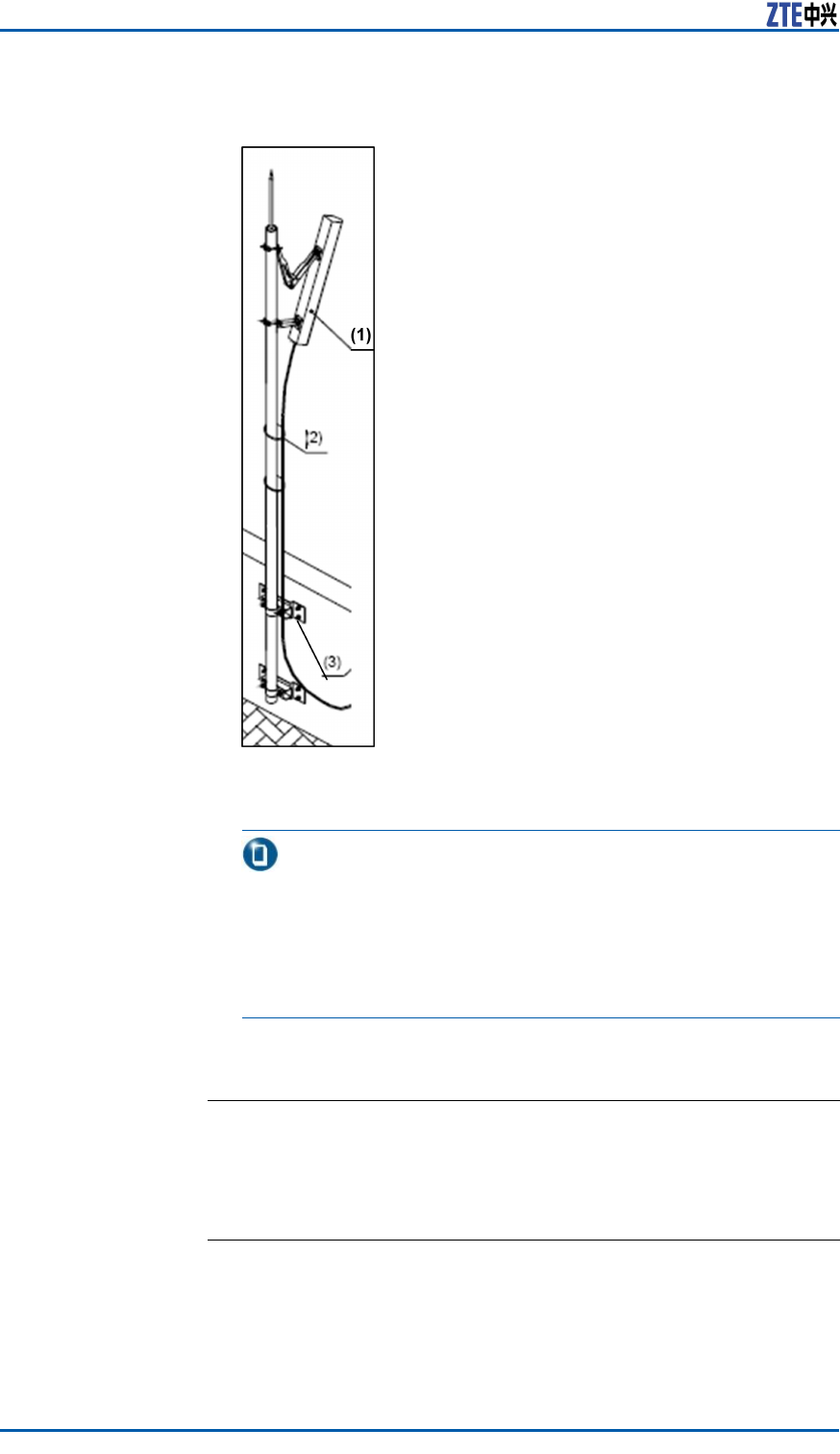
ZXSDRR8860InstallationManual
FIGURE76FEEDERFIXING
1.Antenna
2.Feeder
3.Supportingclips
Note:
�Makesurethatthefeederlaidistightened.
�Thebendingradiusofthefeederisnolessthan20times
ofmainfeederradius.Theradiusofsinglebendisnoless
than90mm(3.54inches),andtherepeatedbendradius
isminimum200mm(7.9inches).
7.Connectfeederwiththeantenna.
ENDOFSTEPS.
ResultThefeederissuccessfullyinstalledonthetopofbuilding.
FeederInstallationonTower
PrerequisiteEnsurethatthelabelsareattachedatabout0.3m(1feet)away
frommainfeederatbothends,andarecorrect.
94ConfidentialandProprietaryInformationofZTECORPORATION

Chapter5MainAntennaFeederSystemInstallation
Context
Caution:
�Hoistthemainfeederwithcaretoavoiddamagingit’ssheath.
Ifanypartofsheathisdamaged,thenitmaycausetheentire
feedertobediscarded.
�Takecareforpersonnelsafetywhenhoistingthefeeders.
Thefeederinstallationinvolvesthefollowingssteps:
Steps1.Wrapthemainfeederconnectorwithapieceofaxorananti-
staticplasticbaglledwithfoam,andthenbindittightlywith
cableties.
2.Knotandxthecutfeedercablewithhoistingropeattwo
points.Oneis0.4m(1.5/16feet)awayfromthefeedercon-
nectorandtheotheroneis3.4m(11.2/16feet)away.
Warning:
Avoidfeederandit’sconnectorfromcollidingwiththeiron
tower .
3.Afterhoistingmainfeedercablestothetowertop,xupper
endofcableatmultiplepointstopreventitfromslippingdown
thetower .
ThefeederhoistingisshowninFigure77
ConfidentialandProprietaryInformationofZTECORPORATION95
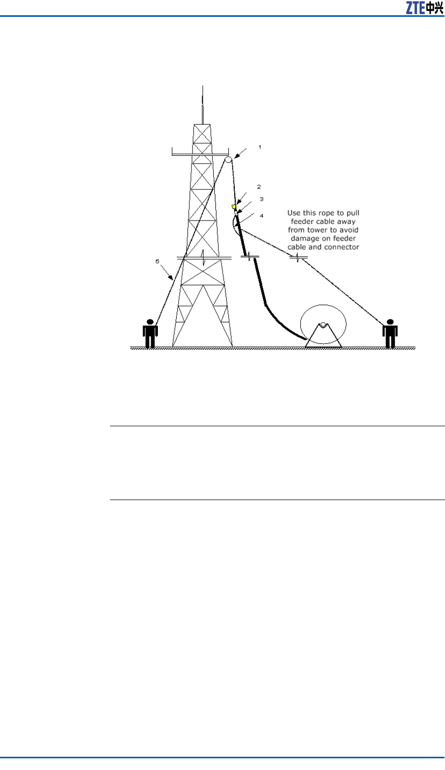
ZXSDRR8860InstallationManual
FIGURE77HOISTINGFEEDERTOTOWER
1.Pulleyblock
2.Feederheadwrap
3.Feederlabel
4.Knotpositionintheupward
rope
5.Downwardrope
ENDOFSTEPS.
ResultThefeederishoistedonthetowersuccessfully.
FeederLayoutPrinciples
Thefeedershouldbelaidinaccordancewiththefollowingprinci-
ples:
�Themainfeedermustbelaidingoodorderandwithoutcross-
ings.
�Thefeederroutemustbedeterminedbeforeconnectingthe
mainfeeder .Marktheactualfeederrouteonadrawingto
avoidreworksduetocrossings.
�Theminimumbendingradiusofthemainfeedershouldbe
greaterthan20timesofthemainfeederradius.Thebending
radiusofasinglebendshouldbegreaterthan90mm(3.54
inches).Theminimumbendingradiusofrepeatedbendsis
200mm(8inches).
�Ifmorethanonetriplefeederclipsareusedinfeederrouting,
thenmaximumdistancebetweentriplefeederclipsshouldbe
notmorethan1.65m(5.41feet).
96ConfidentialandProprietaryInformationofZTECORPORATION
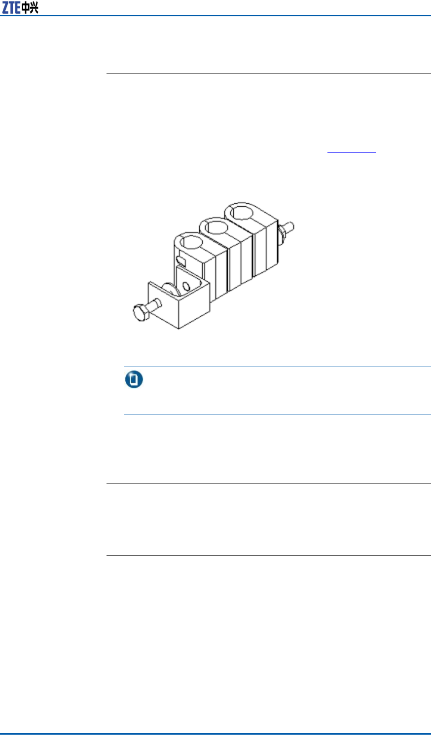
Chapter5MainAntennaFeederSystemInstallation
FeederFixingProcedures
ContextPerformthefollowingstepstoxthemainfeeder:
Steps1.Firstlyarrangethemainfeederinagoodorder .
2.Fastenmainfeedersfromtopdownwardwiththetriplefeeder
clipsafterarrangingthemainfeeders.Figure78showsthe
appearanceoftriplefeederclip.
FIGURE78TRIPLEFEEDERCLIPAPPEARANCE
Note:
Donotfastenfeedersatbothendssimultaneously.
3.Keepmainfeedersstraightandinagoodorderwithoutany
bulgesbetweenthetriplefeederclips.
4.Tightenthetriplefeederclipsrmly.
ENDOFSTEPS.
ResultThefeederxingiscompleted.
FeederGroundingPrinciple
Thegroundingprinciplesofmainfeederisasfollows:
�Toinstallmainantennafeedersystemontower ,mainfeeder
mustbeinstalledwithfeedergroundingclipsatleastinthree
places:
�Towerplatform
�Theplacewherethemainfeederleavesthetower
�Theplacebeforewherethemainfeederisconnectedtothe
chassis
ConfidentialandProprietaryInformationofZTECORPORATION97
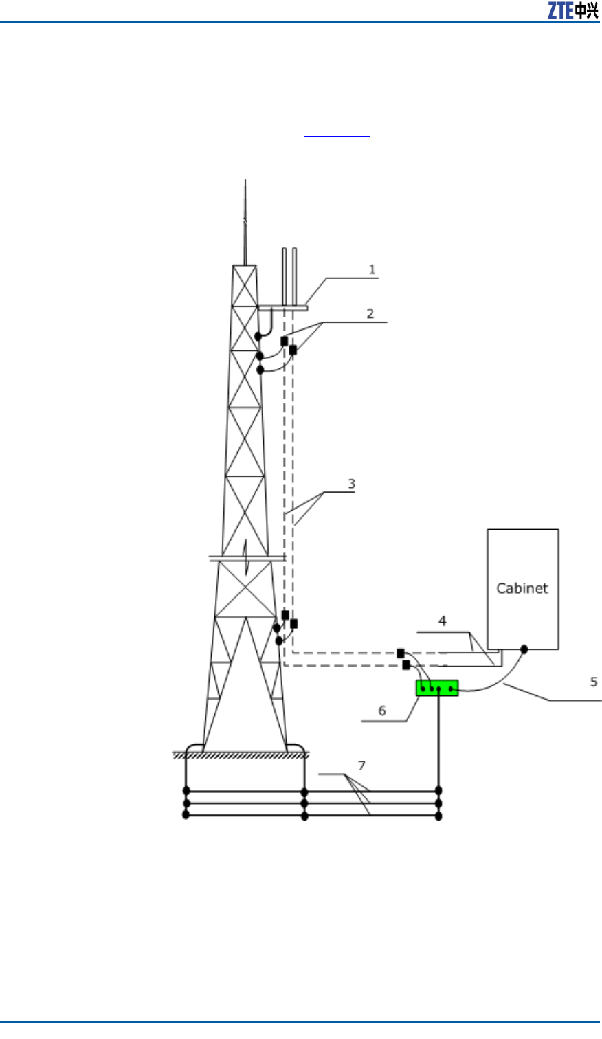
ZXSDRR8860InstallationManual
Whenthemainfeederisover60m(197feet)inlength,feeder
groundingclipsmustbeaddedinthemiddle.Generally,a
groundingclipmustbeinstalledonthefeederevery20m(65.6
feet),asshowninFigure79.
FIGURE79FEEDERGROUNDINGSCHEMATICDIAGRAM
1.Towerplatform
2.Feedergroundingclip
3.Feeder
4.Cabinetjumper
5.Groundingcable
6.Groundingbusbar
7.Groundgrid
�Toinstallthemainantennafeedersystemontheroof,itsan-
tennasupportandcablerackmustbeweldedtothelight-
ningprotectiongridofthebuilding.Themainfeedermust
begroundedatthreeplaces:
98ConfidentialandProprietaryInformationofZTECORPORATION

Chapter5MainAntennaFeederSystemInstallation
�Theplacewherefeederleavesthepole
�Theplacewherefeederleavestheroof
�Theplacebeforewherethemainfeederisconnectedtothe
jumperofthechassis.
�Theoutdoorwiringladderofthemainfeedermustbe
grounded.
FeederGroundingClipsInstallation
ThefeedergroundingclipsinstallationofZXSDRR8860isdescribed
below.
Grounding
Requirements
Ensurethefollowinggroundingrequirementswhileinstalling
feedergroundingclips:
�Roofinstallationmode
Inroofinstallation,thefollowingitemsmustbegroundedto
buildgroundingnetwork:
�Mainantennassystem
�Antennapole
�Outdoorcablingrackorcablingladder
Groundthemainfeedercableatoneposition,whereitleaves
antennapole.Ifthefeedercableisratherlong,addgrounding
pointsaccordingtofeederlength.
�Towerinstallationmode
Usuallyatleasttwofeedergroundingclipsarerequiredtobe
installedintowerinstallationmode.Groundthefeedercable
atthefollowingpositions:
�Whereitleavesantennainstallationpole
�Whereitleavesirontower
Whenthefeedercableislongerthan60m(197feet),install
agroundingcliponthefeedercableatevery20m(66feet)
distance.
Ifoutdoorcablingrackoroutdoorcablingladderisused,
grounditreliably.
Antennapolesandirontowerneedtobegroundedreliably.
Figure80illustratesgroundingsystemintowerinstallation.
ConfidentialandProprietaryInformationofZTECORPORATION99
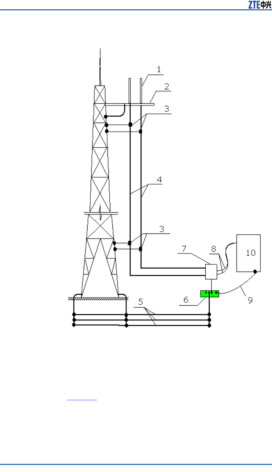
ZXSDRR8860InstallationManual
FIGURE80GROUNDINGSYSTEM
1.Antenna
2.Irontowerplatform
3.Feedergroundingclip
4.Feedercable
5.Groundinggrid
6.Groundingbar
7.Lightningarrester
8.Cabinetjumper
9.35mm2(2AWG)groundingcable
10.ZXSDRR8860cabinet
GroundingBar
Introduction
Groundinggridandgroundingbarareusuallyinstalledbytheoper-
atoremployees.Andthegroundingbarisrequiredtobeinstalled
wheretheengineeringdesigndetermineswithexpansionbolts.
Figure81illustratesthestructureofthegroundingbar .
100ConfidentialandProprietaryInformationofZTECORPORATION
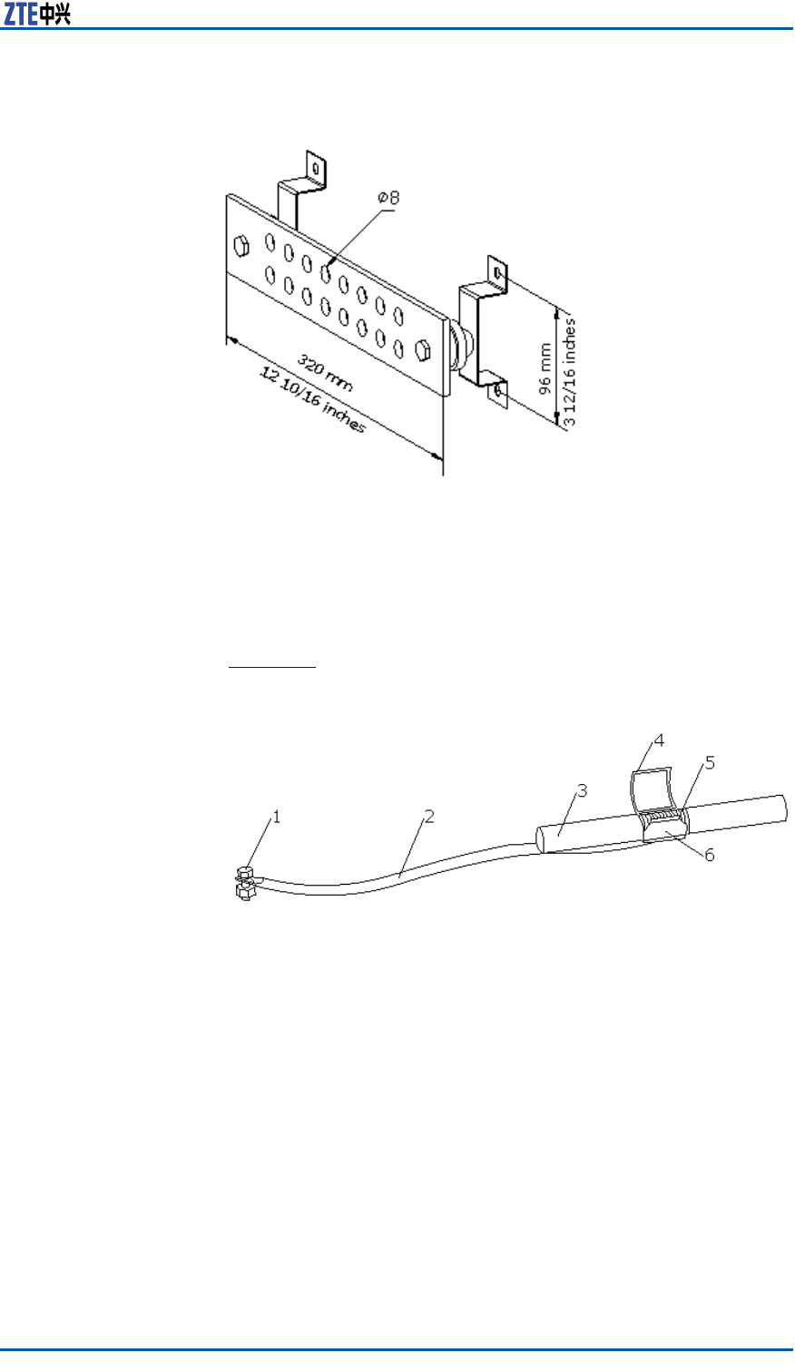
Chapter5MainAntennaFeederSystemInstallation
FIGURE81GROUNDINGBARSTRUCTURE
InstallationStepsPerformthefollowingstepstoinstallgroundingclip.
1.Preparerequiredtoolsincludingpaperknife,atheadscrew-
drivers,andwrenchandsharp-nosepliers.
2.Peeloff7/8"sheathaccordingtosizeofgroundingclipatthe
positions.
Figure82illustratesstructureofgroundingclip.
FIGURE82GROUNDINGCLIP
1.Groundingend
2.Groundingcable
3.Feedercable
4.Groundingspringlock
5.Feederexternalcoppercore
6.Groundingcablecopperpiece
3.Clampthefeederexternalconductorwithgroundingcablecop-
persheetandlockingspringplate.
4.Laygroundingcablefacingtothegroundingnetwork.Avoid
bendingorfolding.Andkeeptheincludedangelbetween
groundingcableandfeedercablelessthan15°.
�Intowerinstallationmode,groundingcableisinstalled
downwardsandnallyconnectedtotower
�Inroofinstallationmode,groundingcableisinstalledinthe
samedirectionwithfeedercables.
5.Makejointofgroundingclipandfeederwaterproofusingwa-
terproofadhesivetapes,thenuseinsulationtapestocoverthe
joint.
ConfidentialandProprietaryInformationofZTECORPORATION101

ZXSDRR8860InstallationManual
6.Connectthegroundingendofthegroundingcliptotheground-
ingnetwork.
�Connectittothemaintowerbodyintowerinstallation
mode.
�Connectittothegroundedcablingrackinroofinstallation
mode.
Whenconnecting,removethepaintandoxideatconnection
placewithinaradiusof13mm(8/16inches)aroundthejoint,
anddaubtheplacewithantioxidantcreamtoensuregoodelec-
triccontact.Afterconnecting,paintthejointwithanticorrosive
paint.
Note:
Donotinstallgroundingclipincaseofanylightningstrike.
ConnectJumperandFeeder
PrerequisiteFeederconnectorandjumperconnectorisprepared.
ContextThefollowingproceduredetailthefeederandjumperconnection.
Steps1.Fixthe1/2inchjumperconnectorwiththefeederconnector ,
andscrewthemtightly.
2.SealtheconnectorswithwaterproofadhesivetapesandPVC
tapes.
ENDOFSTEPS.
ResultThejumperisconnectedwiththefeedersuccessfully.
InstallingFeeder
Hermetic-window
ContextInstallationrequirementsaredescribedasfollows:
�Theinstallationpositionofhermeticwindowshouldbecloseto
acabletraypossibly.
�Thehermeticwindowcanbemountedagainstanindoorwall
oroutdoorwallandthesideofprotuberantmetalcirclesmust
puttowardsoutdoors
�Ifthefeederentersintoaroomfromaroof,thehermeticwin-
dowcanbemountedontheroofandthesideofprotuberant
metalcirclesmustputtowardsoutdoors.
Thefollowdescribesthestepsof12holehermeticwindowinstalled
againstthewall.
102ConfidentialandProprietaryInformationofZTECORPORATION
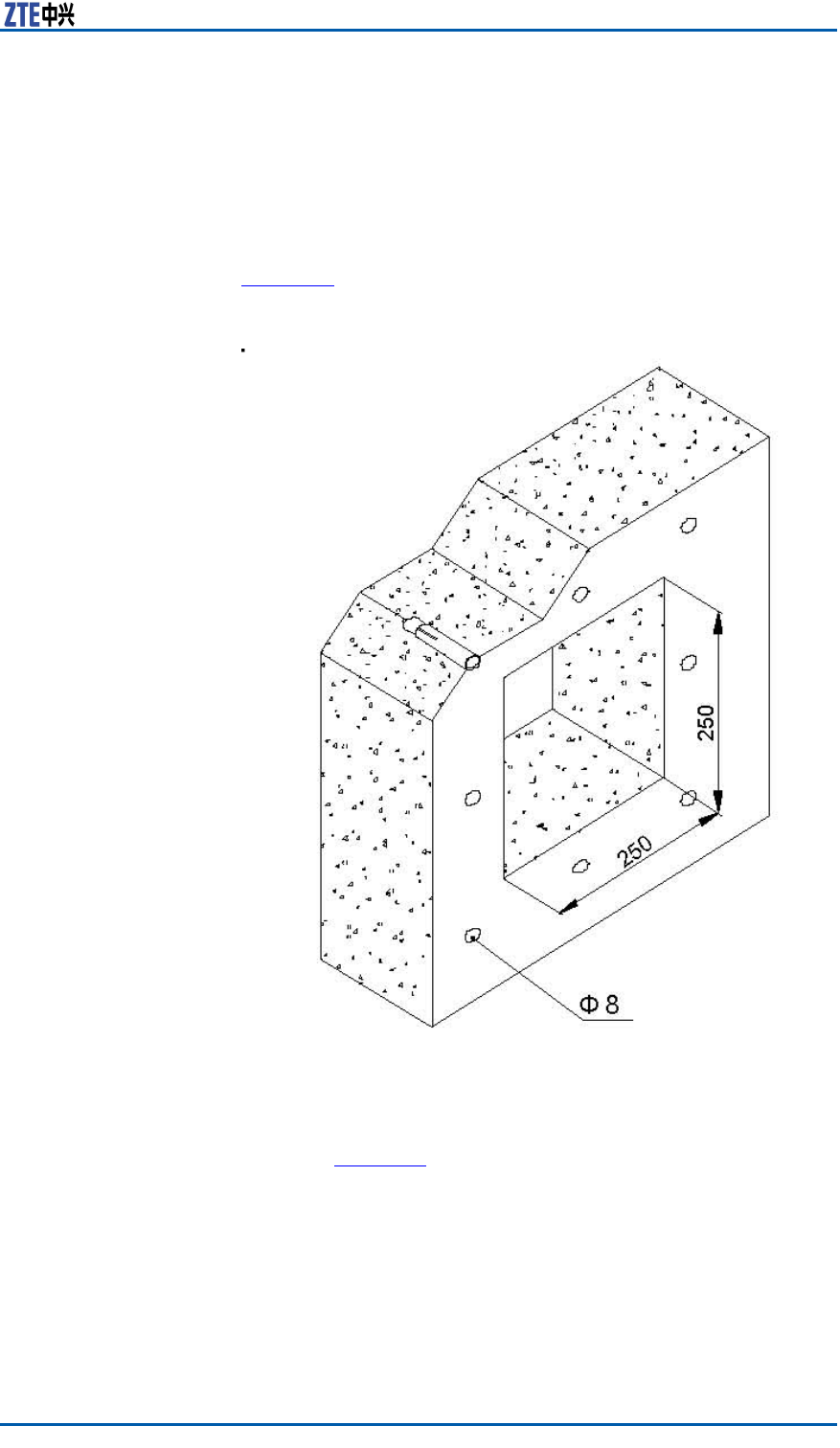
Chapter5MainAntennaFeederSystemInstallation
Steps1.Accordingtotherequirementsofengineeringdesigndrawing
andthedimensionofhermeticwindow,makesuretheinstal-
lationpositionofhermeticwindowonthewallandatthesame
timemarkholepositionsofexpansionboltsandahollowroom
leftforthehermeticwindow.
2.Cuta250mm×250mmsquarebigholeandthendrilleight
holesofexpansionblotswithapercussivedrill,asshownin
Figure83.
FIGURE83INSTALLATIONHOLEPOSITIONS(UNIT:MM)
3.Fixafeederhermetic-windowpanelwithexpansionbolts,as
showninFigure84.Whileinstallingexpansionbolts,rstput
aatwasherandthenaspringwasher .
ConfidentialandProprietaryInformationofZTECORPORATION103
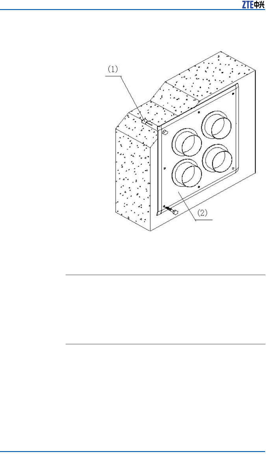
ZXSDRR8860InstallationManual
FIGURE84HERMETICWINDOWINSTALLATION
1.M8×80expansionbolt2.Feederhermetic-window
panel
ENDOFSTEPS.
FeederIndoorIngoing
FeederIndoorArrangementPrinciple
Thearrangementprinciplesoffeederintoaroomcomplywiththe
following:
�Therearefourbigholesona12–holefeederhermetic-window.
Everybigholehasthreesmallholes,everyofwhichafeeder
passesthrough.
�AccordingtotheserialNo.ontheengineeringlabelsattached
onthefeeder ,layoutthefeederthroughthreesmallholesin
thesamebigholeclockwiseoranticlockwise.
104ConfidentialandProprietaryInformationofZTECORPORATION
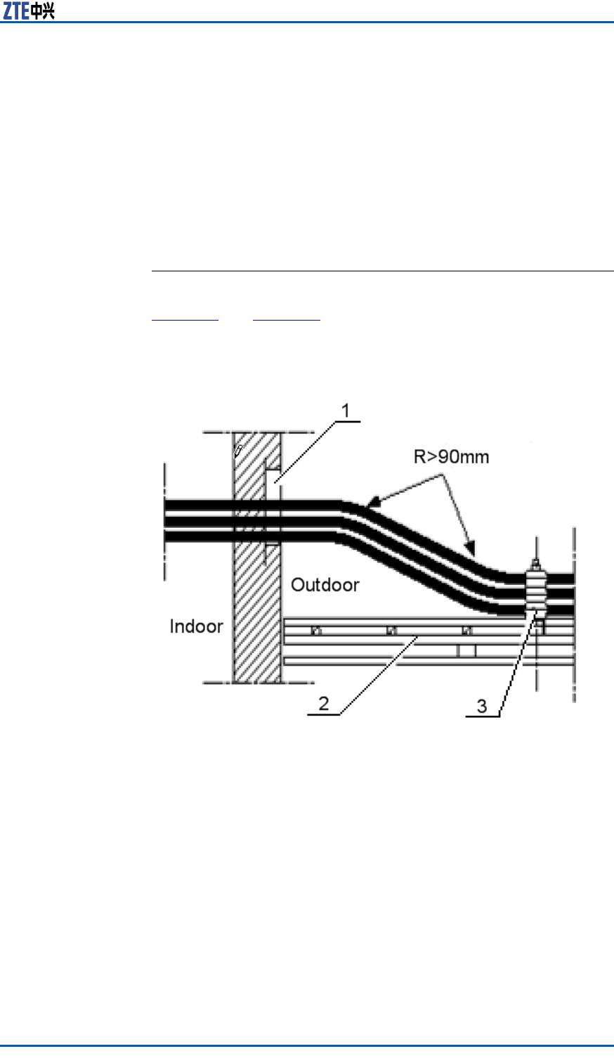
Chapter5MainAntennaFeederSystemInstallation
�Feederlayoutinthehermeticwindowshouldbeconvenientfor
capacityexpansion.Donotmodifytheinitialfeederlayoutin
thehermeticwindowduringcapacityexpansion,andonlyallow
addingfeederormodifyjumperconnectionofcabinet.
�Feederlayoutinthehermeticwindowshouldbeconvenient
forlayoutonacabletrayandconnectiontoacabinet.The
feedershouldbeparallelandnotcrossedduringroutingand
connecting.
LeadingMainFeederintoRoom
ContextFigure85andFigure86showtwocommonmodesofmainfeeder
intoaroom.Whilethemainfeederisenteringintotheequipment
room,donotbringwaterintotheequipmentroom.
FIGURE85FEEDERINTOROOMMODE(1)
1.Feederwindow
2.Cabletray
3.Feederkit
ConfidentialandProprietaryInformationofZTECORPORATION105
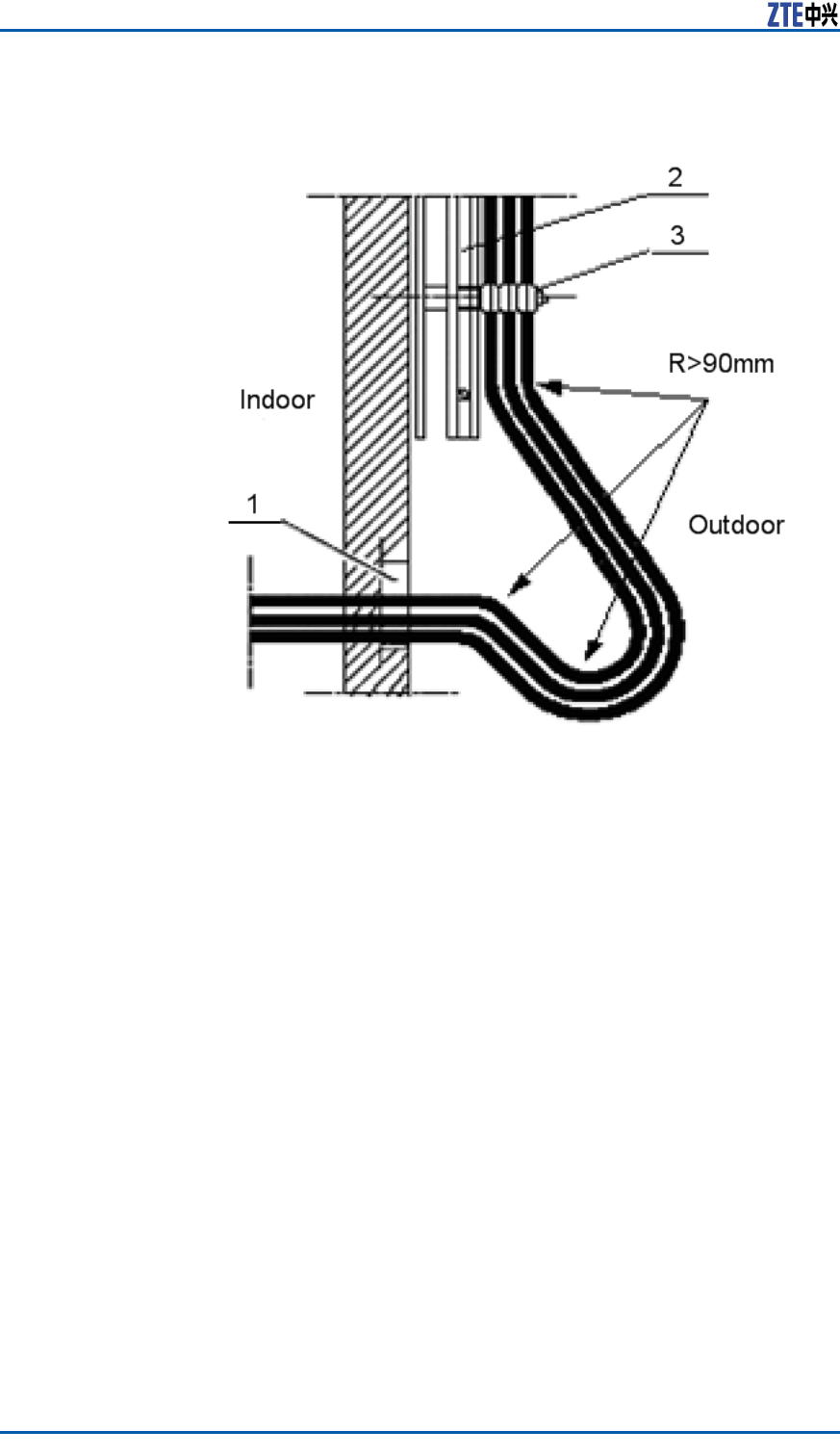
ZXSDRR8860InstallationManual
FIGURE86FEEDERINTOROOMMODE(2)
1.Feederwindow
2.Cabletray
3.Feederkit
Steps1.Unscrewafastnesshoopoffeederwindowtoproperextent.
Pulloutsealingcoversofsmallholesthatthefeederpasses
through.
2.Leadthemainfeederintotheequipmentroom.Whenthemain
feederentersintoanindoorcabletrayfromanoutdoorcable
tray,itisnecessaryfortwoinstallationpersonnel’scooperation
respectivelyindoorsandoutdoors.Inthisway,avoiddamaging
themainfeederandotherindoordevicesbyimproperforce
duringinstallation.Screwdownthefastnesshoopuntilthe
mainfeederispulltothespeciedposition.
3.Cutthemainfeeder .Beforeandaftercutting,makesuretem-
porarylabelsonthemainfeederintact.
106ConfidentialandProprietaryInformationofZTECORPORATION

Chapter5MainAntennaFeederSystemInstallation
Note:
Accordingtodetailedequipmentenvironment(forexample,
cabinetinstallationposition,jumperlengthonthecabinettop,
arrestercongurationorarresterrackinstallationposition),the
bendingradiusrequirementofmainfeederandthebeautiful
requirementofcablelayoutintheequipmentroom,selecta
cuttingpositionofmainfeedercable.
4.Makeanindoorconnectorofmainfeeder .
5.Connectthemainfeederwithanarrester .
Note:
�Foranarresterwithoutgroundcable,duringinstallation,
connectthearrestertothemainfeederdirectly.
�Foranarresterwithanarresterrack,duringinstallation,
adjusteverymainfeedercarefully.Makesureascrewfas-
tenerconnectedwellwhichconnectsthemainfeedercon-
nectorwiththearrester .
ENDOFSTEPS.
InstallingTop-equipmentJumper
ContextTherequirementsofjumperinstallationareasfollows:
�Jumperlayoutfromcabinettoptocabletrayshouldbeparallel
andorderly,butnotcrossed.
�Duringrouting,thejumpermustpassthroughthecabletray
innertoitsupperside.Prohibitjumpingthecabletrayoutsides
directly.
�Thebendingofjumperisreasonableandnatural.Suggestthat
thebendingradiusofjumpershouldbetwentytimesmorethan
itsdiameter .
�Duringlayoutfromcabinettoptocabletray,thetensile
strengthforthejumpershouldbemoderate.
�Thejumpershouldbeboundwitheveryrailofcabletray.The
directionsofallwirefastenerskeepconsistentandafterbind-
ing,thewirefastenersarecutatly.
�Labelsmustbeafxedtoallindoorjumpersata100mmdis-
tancefrombothendsofjumper .
Steps1.Thejumperpassesthroughawiringslotonthetopofcabinet.
2.ConnectaDINconnectoroffeedertoanANTinterfaceofRSU.
3.ConnecttheotherDINconnectorofjumpertoaDINconnector
offeeder .
ConfidentialandProprietaryInformationofZTECORPORATION107
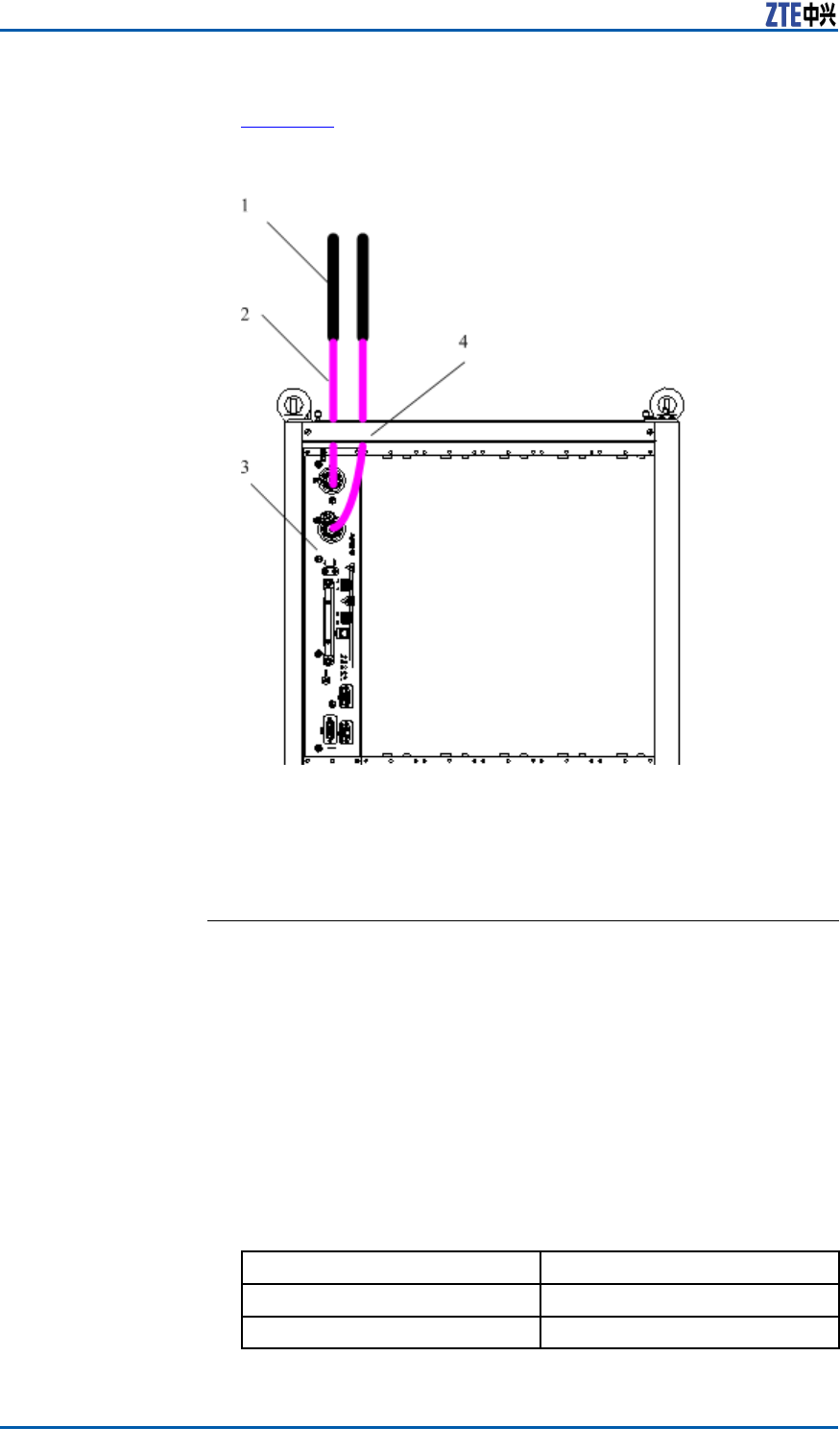
ZXSDRR8860InstallationManual
Figure87showstheinstallationprocess.
FIGURE87ANTENNA,FEEDERANDJUMPERINSTALLATION
1.Feeder
2.Jumper
3.RSU
4.Wiringslot
4.Afxjumperengineeringlabels.
ENDOFSTEPS.
PerformingAntennaFeeder
SystemTest
Steps1.Afterunpacking,checkwhetherasurfaceofantennaandan-
tennaconnectorsareundamaged.
2.Afterconnectingantennaandjumper ,andscrewingdownthe
connector ,checktheSVWRwithaSVWRtester .
IfThen
SVWR≥1.5Unqualied
SVWR1.5Qualied
108ConfidentialandProprietaryInformationofZTECORPORATION
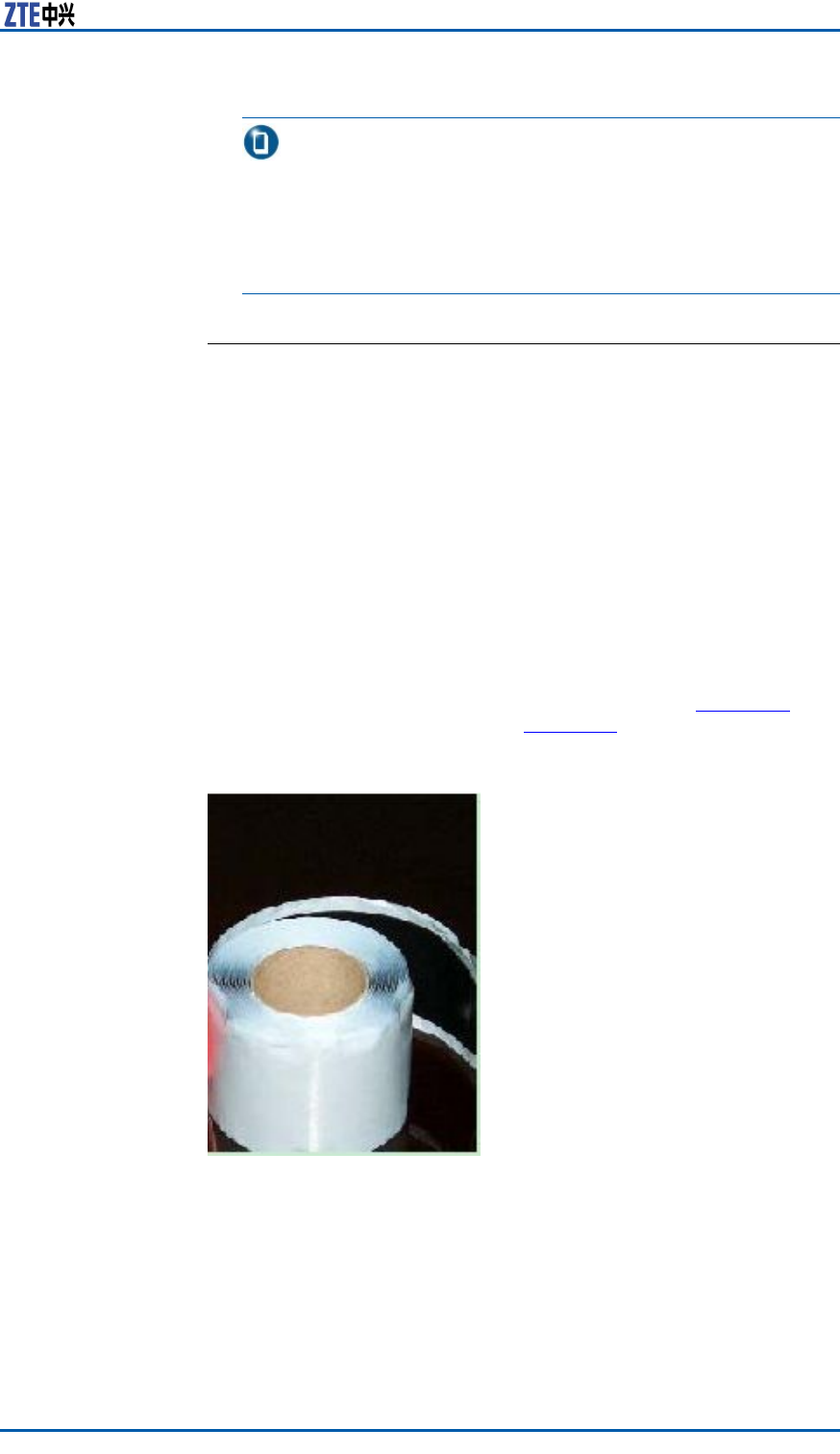
Chapter5MainAntennaFeederSystemInstallation
Note:
Duringmeasuring,moveanantennaorchangetheposition
ofantenna.IftheSVWRsinalldirectionsareunqualied,it
indicatesthattheantennaisfaulty.IftheSVWRsinsome
directionsareunqualied,checktheantennaafterthewhole
antennaandfeedersysteminstalledcompletely.
ENDOFSTEPS.
PerformingOutdoor-connec
torWaterproofProcessing
PrerequisiteWhileanoverallinstallationofantennafeedersystemiscompleted
andgetsthroughatest,performwaterproofprocessingforacon-
nectorbetweenoutdoorjumperandtowertopamplieraswellas
aconnectorbetweenjumperandfeederimmediately.
ContextTherearetwotypesofadhesivetapesforwaterproofprocessing:
waterproofinsulationadhesivetape,asshowninFigure88,and
PVCadhesivetape,asshowninFigure89.
FIGURE88WATERPROOFINSULATIONADHESIVETAPE
ConfidentialandProprietaryInformationofZTECORPORATION109
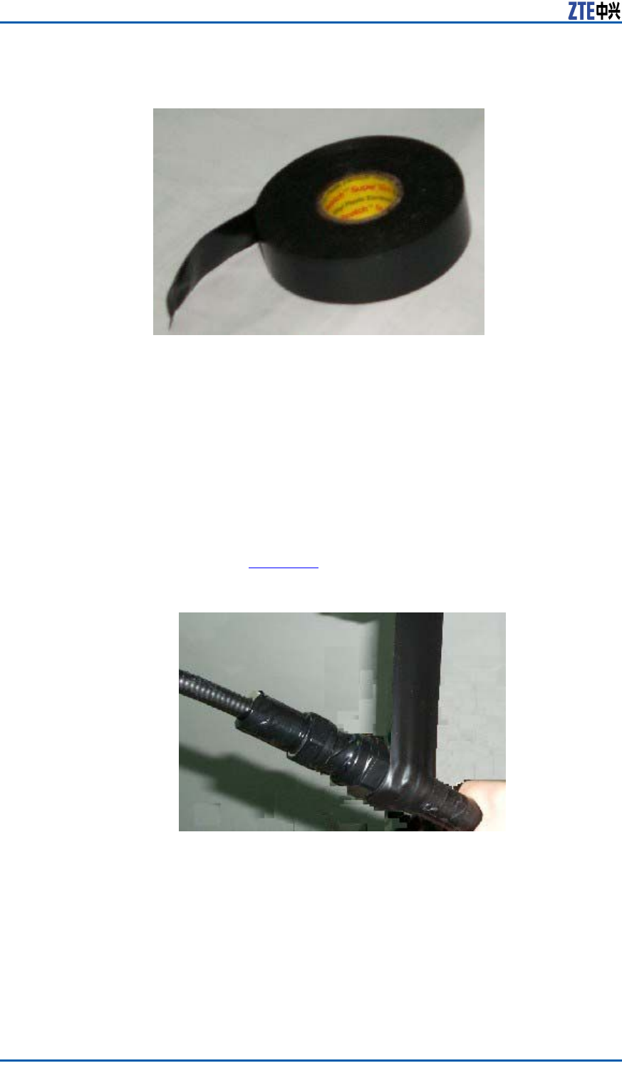
ZXSDRR8860InstallationManual
FIGURE89PVCADHESIVETAPE
Steps1.Cleanoutdustandstainonthefeederconnectororfeeder
groundingclip.
2.Expandthewaterproofinsulationadhesivetapeandstripoff
releasepaper .Theadhesivetapestickstotheconnectoror
thefeederwhichis20–50mmawayfromthelowerendof
groundingclip.
3.Extendtheadhesivetapetoupto1/2–3/4oftheformer
width,inordertokeepacertainextensionstrength.Bindthe
feederinanoverlappingwayfromlowertoupperandtheup-
peradhesivetapecoversahalfoftheloweradhesivetape,as
showninFigure90.
FIGURE90WATERPROOFINSULATIONADHESIVETAPEWRAP
110ConfidentialandProprietaryInformationofZTECORPORATION
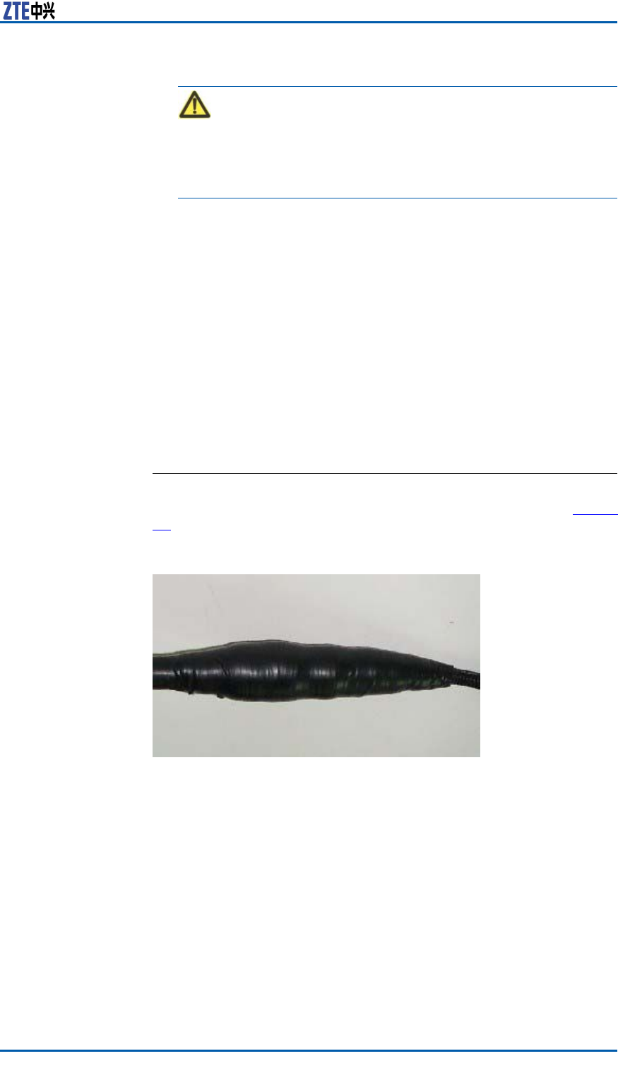
Chapter5MainAntennaFeederSystemInstallation
Caution:
Theextendedwidthofadhesivetapeisnotover1/2thanthe
formerwidth,orelsedestroymolecularstructureofadhesive
tapeduetoextensiontoomuch.
4.Whilewrappingtotheconnector ,repeatitfortwiceandthe
sequencerespectivelyis:fromuppertolowerandfromlower
toupper .
5.Afterwrappingthewaterproofinsulationadhesivetape,press
theadhesivetapeatthebindingwithhandsmakeitafxed
tightly.
6.WrapalayerPVCadhesivetapearoundthewaterproofinsula-
tionadhesivetapetoavoidabrasionandaging.
7.WrapthePVCadhesivetapeinanoverlappingmode,similarto
thewaterproofinsulationadhesivetape.Theoverlappingrate
isabout1/2.Wrapthreelayersintotal,andthesequence
respectivelyis:fromlowertoupper ,fromuppertolowerand
fromlowertoupper .Makesureproperstretchstrengthduring
wrapping.
ENDOFSTEPS.
ResultTheappearanceofconnectorafterprocessingisasshowninFigure
91.
FIGURE91CONNECTORAFTERPROCESSING
PerformingFeeder
Hermetic-window
WaterproofProcessing
ContextTherearetwotypesoffeederhermetic-window:
ConfidentialandProprietaryInformationofZTECORPORATION111
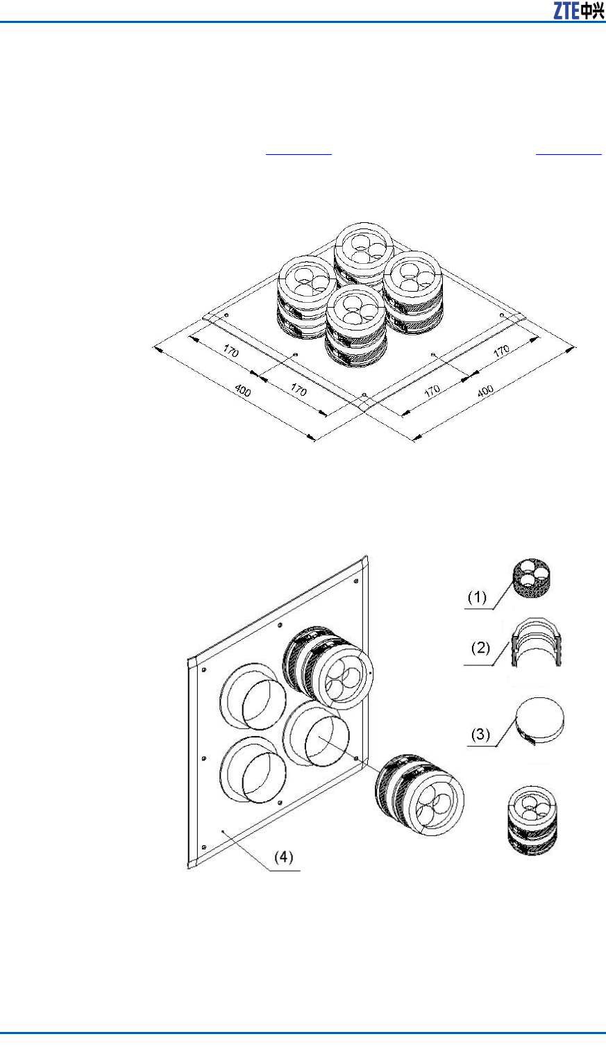
ZXSDRR8860InstallationManual
�12holefeederhermetic-window
�27holefeederhermetic-window
Normally,adoptthe12holefeederhermetic-window,itsdimen-
sionasshowninFigure92anditsstructureasshowninFigure93.
FIGURE92FEEDERHERMETIC-WINDOWDIMENSION(UNIT:MM)
FIGURE9312FEEDERHERMETIC-WINDOWSTRUCTURE
Installationrequirements:
�Theinstallationpositionofhermeticwindowshouldbecloseto
acabletray.
112ConfidentialandProprietaryInformationofZTECORPORATION
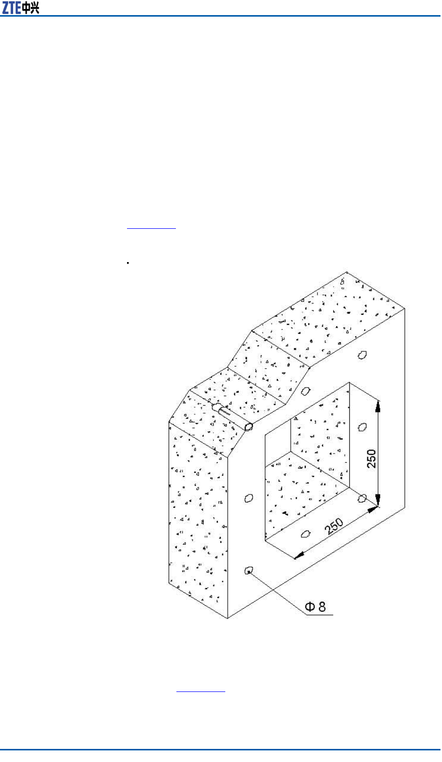
Chapter5MainAntennaFeederSystemInstallation
�Thehermeticwindowcanbemountedagainstanindoorwall
oroutdoorwallandthesideofprotuberantmetalcirclesmust
puttowardsoutdoors.
�Ifthefeederentersintoaroomfromaroof,thehermeticwin-
dowcanbemountedagainsttheroofandhesideofprotuber-
antmetalcirclesmustputtowardsoutdoors.
Steps1.Accordingtotherequirementsofengineeringdesigndrawing
andthedimensionofhermeticwindow,makesuretheinstal-
lationpositionofhermeticwindowonthewallandatthesame
timemarkholepositionsofexpansionboltsandahollowroom
leftforthehermeticwindow.
2.Cuta250mm×250mmsquarebigholeandthendrilleight
holesofexpansionblotswithapercussivedrill,asshownin
Figure94.
FIGURE94INSTALLATIONHOLEPOSITIONS(UNIT:MM)
3.Fixafeederhermetic-windowpanelwithexpansionbolts,as
showninFigure95.
Whileinstallingexpansionbolts,aatwasherandaspring
washermustbeinstalledinturn.
ConfidentialandProprietaryInformationofZTECORPORATION113
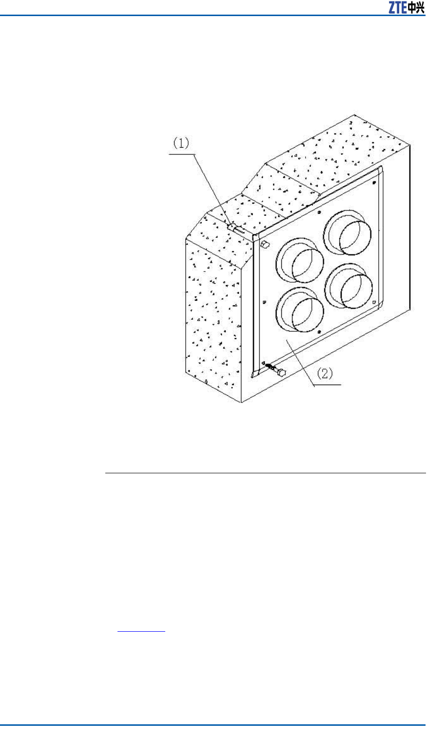
ZXSDRR8860InstallationManual
Asealingwasherandasealingcovermaybeinstalledtogether
withfeederenteringintotheroom.
FIGURE95FEEDERHERMETIC-WINDOWINSTALLATION
1.M8×80expansionbolt2.Feederhermetic-window
panel
ENDOFSTEPS.
CabinetJumperInstallation
Description
TheZXSDRR8860cabinetisequippedwithtwoNtypefemalecon-
nectors.TheseconnectorsareconnectedtoNtypemaleconnec-
torsof1/2"jumpers.Thecabinetjumperconnectionisasshown
inFigure96.
114ConfidentialandProprietaryInformationofZTECORPORATION
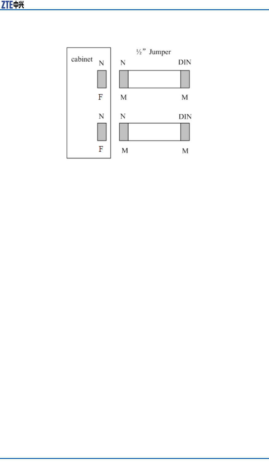
Chapter5MainAntennaFeederSystemInstallation
FIGURE96CABINETJUMPERS
DINmeansthattheconnectortypeisDIN.
NmeansthattheconnectortypeisN.
"M"indicatesmaleconnectorand"F"indicatesfemaleconnector .
Connectthejumperwiththecabinet.Makesuretoconnectthe
respectiveconnectorswithsimilartypes,suchasNtypeconnector
ofjumpershouldbeconnectedwithNtypeinterfaceofthecabinet
andMtypeconnectorofjumpershouldbeconnectedwithMtype
interfaceofthecabinet.
VSWRTest
Aftertheinstallationofallantennafeedersandjumpers,conduct
VSWRtest.TheVSWRmustbelessthan1.3.Otherwise,check
allmainantennaandfeedersystem,thatincludes:
�Checkwhethertheantennafeeders,connectors,andjumpers
areintact.
�Ensurethattheconnectionbetweenallpartsareproper .
�Checkwhethertheantennafeederinstallationisperfect.
ConfidentialandProprietaryInformationofZTECORPORATION115

ZXSDRR8860InstallationManual
Thispageisintentionallyblank.
116ConfidentialandProprietaryInformationofZTECORPORATION

Chapter6
HardwareInstallation
Inspection
TableofContents:
CheckingCabinetInstallation............................................117
CheckingCableInstallation...............................................117
CheckingMainAntennaSystemInstallation........................120
CheckingCabinet
Installation
Steps1.Ensurethatthecabinetinstallationpositioncomplieswiththe
engineeringdesigndrawing.
2.Erectcabinetrmlysoastoresistanearthquakemeasuring
upto7.0onRichterscale.
3.Ensurethathorizontalandverticalerrorislessthan3mm.
4.Ensurethatcabinetsurfaceiscleanandtidyandcoveredwell
byoilpaint.Allpartsofthecabinetarecompleteandallmark-
ingonthecabinetarecorrect,clearandcomplete.
5.Ensureallscrewsarexedtightwithatwashersorspring
washers.
ENDOFSTEPS.
CheckingCableInstallation
CablesInstallationGeneral
Specification
OpticalFiber
Note:
ConfidentialandProprietaryInformationofZTECORPORATION117

ZXSDRR8860InstallationManual
Thelengthofopticalberisdecidedbyengineeringsurvey(1Tx,
1Rx).
Thetechnicalspecicationsofopticalberareasfollows:
�TheopticalberisasinglemodewithEndBadoptingtwo
DLC/PCconnectors.
�Theinsertionlossislessthat0.3dB.
�Thereturnlossislessthan45dB.
�Ifopticalberistobeusedoutdoor ,then
�Takewaterproofandanti-ultravioletprotectionmeasures.
�Makesurethatworkingtemperatureisinbetween-40to
80oC.
�Thesheathofopticalberisblackincolorwithadiameterof
7mm.Underthesheath,therearetwocoresopticalwires
(yellowandbluecolor)withsubstantialamountofprotection
padding.
�Themaximumdistancebetweencoreopticalwires(including
bothDLC/PCconnectors)andsheathedopticalberis350mm.
�ZTEsupplies15m,25m,35m.50m,70m,100m,and130
mlongbercables.
�The20mmlongblackPyrocondensationcannulashouldbe
addedinbetweenopticalcorewiresandsheathedopticalber .
�Thelabelattachedatbothendsshouldsatisfytherequirements
ofZTECableDesigningCriteria–LabelDesigningandUsage
Requirements.
AISGCableThefollowingarethetechnicalspecicationofAISGcable:
�Table16illustratestheconnectionrelationshipofbothends.
MakesuretoencloseEndAconnectionbyblackcannulacom-
pletelyafterconnecting.
TABLE16CONNECTIONRELATIONSHIP
Serial
Number
Signal
Definit
ion
EndAPin
Number
EndBPin
Number
Connected
Cable
1485+Pin3Pin1-
2485-Pin5Pin2-
328VPin6Pin3,4Twocablesfrom
Pin6ofAend
areweldedto
Pin3and4of
Bend.
428VGNDPin7Pin5,6Twocablesfrom
Pin7ofAend
areweldedto
Pin5and6of
Bend.
�ThePin6andPin7(SeeT able16)areneededtobewelded
withtwocables.
118ConfidentialandProprietaryInformationofZTECORPORATION

Chapter6HardwareInstallationInspection
�TheEndAconnectorshouldbeequippedwithmetaldust-proof
cover
�Thelabelsprintingandpastingshouldsatisfytherequirements
ofQ/ZX04.113.4CableDesigningCriteria–LabelDesigning
andUsageRequirements.
MonitoringCableThefollowingarethetechnicalspecicationofmonitoringcable:
�TheEndAisa37-pinfemaleconnector .
�EndBisanopenendwithoutanyconnector .Theconnectorat
theEndBshouldbepreparedon-siteaccordingtotheon-site
requirements.
�MakesurethatconnectorattheEndAisproperlywelded.
�Thelabelattachedatbothendsshouldsatisfytherequirements
ofZTECableDesigningCriteria–LabelDesigningandUsage
Requirements.
�Table17showstheconnectionrelationshipofEndA.
TABLE17CONNECTIONRELATIONSHIP
EndA(Pins)ColorSignalDefinition
15/16White/blueDrycontact4-/+
17/18White/orangeDrycontact3-/+
19/20White/greenDrycontact2-/+
21/22White/brownDrycontact1-/+
23/24Red/blue485Rx-/+
25/26Red/orange485Tx-/+
OtherPinsarefreeOthercorewiresare
free
PowerandGroundingCables
InstallationCheck
ContextEnsurethepowerandgroundingcablesinstallationisdoneinac-
cordancewiththefollowingchecks:
Steps1.Thepowerandgroundingcablesarelaidseparatelyfromother
cables.Ifthepowerandgroundingcablesaretobelaidpar-
allelwithothercables,thenatleastadistanceof20cmis
maintainedbetweenthem.
2.Thecablelabelsareintactonbothsidesofpowerandground-
ingcables.Thelabelsareattachedatalmost2cmfromcable
copperlug.
3.Entirepowerandgroundingcablesaremadefromonematerial
withnoconnectionsinbetween.
4.Asinglegroundingpointonthegroundingbusbarjustconnects
toapieceofequipment.
5.Copperlugsonbothendsofpowerandgroundingcablesare
solderedorpressedrmly.
ConfidentialandProprietaryInformationofZTECORPORATION119

ZXSDRR8860InstallationManual
6.Theshortestroutebetweenthegroundingcablesandground-
ingbusbarisadopted.
7.Powerandgroundingcablesatconnectingterminalsandlug
handlesareproperlyinsulatedusingeitherinsulatedtapesor
heatshrinktubes.
8.Theredundantlengthofpowerandgroundingcablesiscutto
avoidwrappingeachother .
ENDOFSTEPS.
OpticalFiberInstallationCheck
ContextThebercableinstallationshouldmeetthefollowingspecica-
tions:
Steps1.Donotfoldopticalberat90o.Foropticalberthatistobelaid
outdoors,minimaltwistradiusshouldbeatleastgreaterthan
90mm.Whereasforopticalberthatistobelaidindoors,
minimaltwistradiusshouldbeatleastgreaterthan30mm.
2.Afterinstallation,anysurplusopticalbershouldbeputback
inthebercardforconvenience.
3.Duringinstallation,minimizeopticalbertwistandturn,as
muchaspossible.
4.Thebindingforceshouldbepropertoensurethatbindinggaps
areless0.5m.
5.Makesurethatlabelsatbothendsofopticalberareintact
andclear .
ENDOFSTEPS.
CheckingMainAntenna
SystemInstallation
Steps1.Ensuretheheightofantennaisconsistentwiththenetwork
planning,andtheinstallationpositionisconsistentwiththe
engineeringdesigndrawing.
2.Ensuretheazimuthanddown-tiltoftheantennaisconsistent
withtheengineeringdesigndrawing.
3.Ensuretheantennaiswithintheprotectionareaoflightning
rod.
4.EnsuretheVSWRnotmorethan1.5
5.Ensureproperconnectionbetweenantennaandjumperaswell
asbetweenjumperandmainfeedercorrect.
120ConfidentialandProprietaryInformationofZTECORPORATION

Chapter6HardwareInstallationInspection
6.Makesurethatthejumperandantennaatthejunctionkeep
straightwithin30cmatleast.
ENDOFSTEPS.
ConfidentialandProprietaryInformationofZTECORPORATION121

ZXSDRR8860InstallationManual
Thispageisintentionallyblank.
122ConfidentialandProprietaryInformationofZTECORPORATION

Chapter7
Poweronandoff
TableofContents:
PoweronPreparation.......................................................123
PowerON.......................................................................123
PowerOFF......................................................................123
PoweronPreparation
ContextMakesurethatfollowingconditionsarefullledbeforepowering-on
ZXSDRR8860:
Steps1.Makesurethatinputpowersupplyiswithintheacceptable
range.
2.MakesurethatpowercableconnectedtoZXSDRR8860cabinet
isproperlygrounded.
ENDOFSTEPS.
ResultThepreparationtopoweronthecabinetissuccessfullycompleted.
PowerON
ContextPerformthefollowingstepstopower-ontheZXSDRR8860.
Steps1.ThereisnopowerswitchONtheZXSDRR8860cabinet.Close
theexternalpowerswitchtopoweronZXSDRR8860.
2.DuringpowerON,ifsomeabnormalphenomenaoccurs,dis-
connecttheexternalpowerswitchortheplugimmediately,and
checkthereason.
ENDOFSTEPS.
PowerOFF
ContextPerformthefollowingstepstopowerOFFtheZXSDRR8860.
ConfidentialandProprietaryInformationofZTECORPORATION123

ZXSDRR8860InstallationManual
StepsThereisnopowerswitchontheZXSDRR8860cabinet.Disconnect
theexternalpowerswitchtopoweroffZXSDRR8860.
ENDOFSTEPS.
124ConfidentialandProprietaryInformationofZTECORPORATION

AppendixA
Cabinet-combined
Installation
TableofContents:
ComponentsUsedinCabinet-combiningInstallation....................125
PerformingCabinet-combination...............................................127
ComponentsUsed
inCabinet-combining
Installation
Bycombiningcabinets,theZXSDRR8860cansupport8carrier
sectors.Figure97showstheconnectionforcombiningtwoZXSDR
R8860cabinets.
ConfidentialandProprietaryInformationofZTECORPORATION125
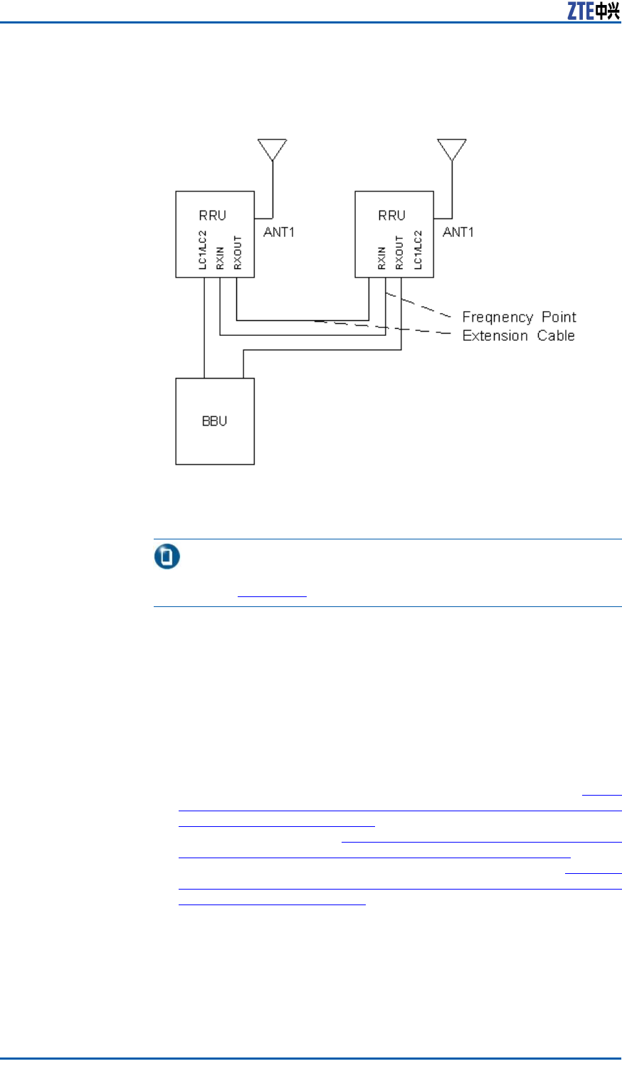
ZXSDRR8860InstallationManual
FIGURE97ZXSDRR8860CABINET-COMBINEDINSTALLATION
CONNECTION
1.FrequencyPointExtensionCable
Note:
TheRRUinFigure97meanstheZXSDRR8860.
Thedescriptionofcabinet-combinedconnectionareasfollows:
1.TwoZXSDRR8860cabinetsareconnectedbytwofrequency
pointextensioncables.
2.TwoZXSDRR8860cabinetsprovidesmutualreceivingdiversity
foreachother .EachZXSDRR8860isequippedwithofapair
ofantennatotransmitandreceivesignals.
Thecomponentsusedinthecabinet-combinedinstallationarede-
scribedasfollows:
1.Whileselectingthepole-mountinstallation,refertoCom-
ponentsUsedinPole-mountInstallationComponentsUsed
inPole-mountInstallation);whileselectingthewall-mount
installation,refertoComponentsUsedinWall-MountIn-
stallationComponentsUsedinWall-mountInstallation;while
selectingthegantry-mountinstallation,refertoCompo-
nentsUsedingantry-mountInstallationComponentsUsedin
Gantry-mountInstallation.
2.Twofrequencypointextensioncablesareprepared.
126ConfidentialandProprietaryInformationofZTECORPORATION

ChapterACabinet-combinedInstallation
PerformingCabinet-combin
ation
Steps1.Selectaproperinstallationmode(pole-mountinstallation,
wall-mountinstallationandgantry-mount)accordingtothe
actualconditionstoinstalltwoZXSDRR8860.
2.Connectthetwofrequencypointextensioncablesasde-
scribedbelow:
1.ConnectEndAofafrequencypointextensioncabletothe
RXininterfaceofaZXSDRR8860andEndBtotheRXout
oftheotherZXSDRR8860.
2.ConnectEndAoftheotherfrequencypointextensioncable
totheRXoutoftheZXSDRR8860andEndBtotheRXinof
theotherZXSDRR8860.
ENDOFSTEPS.
ConfidentialandProprietaryInformationofZTECORPORATION127

ZXSDRR8860InstallationManual
Thispageisintentionallyblank.
128ConfidentialandProprietaryInformationofZTECORPORATION

AppendixB
CascadingCabinet
Installation
TableofContents:
ComponentsUsedinCascadingInstallation................................129
PerformingCabinetCascading..................................................130
ComponentsUsedin
CascadingInstallation
MultipleZXSDRR8860cabinetscanbeconnectedinseriesbyus-
ingopticalbers,formingachainnetwork.Figure98showsthe
cascadedcabinets.
FIGURE98CASCADEDCABINETCONNECTION
ConfidentialandProprietaryInformationofZTECORPORATION129
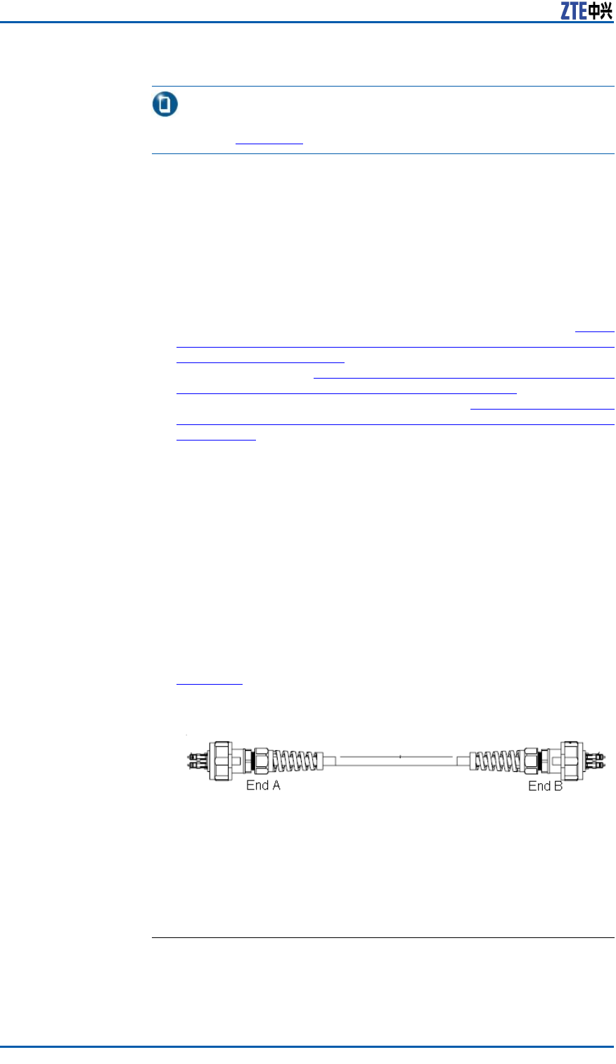
ZXSDRR8860InstallationManual
Note:
TheRRUinFigure98meansZXSDRR8860.
1.OneZXSDRR8860isconnectedtoanotherZXSDRR8860orto
BBUbyopticalbers.EachZXSDRR8860providestwooptical
portsthatareidentiedbyLC1andLC2respectively.
2.Generally,theLC1servetoconnecttheBBUortheupperlevel
ZXSDRR8860whiletheLC2toconnectthelowerlevelZXSDR
R8860.
Thecomponentsusedinthecascadinginstallationaredescribed
asfollows:
1.Whileselectingthepole-mountedinstallation,refertoCom-
ponentsUsedinPole-mountInstallationComponentsUsedin
Pole-mountInstallation);whileselectingthewall-mountedin-
stallation,refertoComponentsUsedinWall-MountInstalla-
tionComponentsUsedinWall-mountInstallation;whileselect-
ingthegantry-mountinstallation,refertoComponentsUsedin
gantry-mountInstallationComponentsUsedinGantry-mount
Installation.
2.Connecttheopticalber .
PerformingCabinet
Cascading
Steps1.Selectaproperinstallationmode(pole-mountorwall-mount)
toinstalltheZXSDRR8860cabinet.
2.Useopticalberstoconnectcabinetsincascade.
Figure99showstheopticalbertoconnectcabinetincascade.
FIGURE99ZXSDRR8860OPTICALFIBERFORCASCADEDCABINET
Followingistheconnectionscheme.
i.ConnectEndAofopticalbertotheLC1/LC2interfaceof
oneZXSDRR8860.
ii.ConnectEndBofopticalbertotheLC1/LC2interfaceof
theotherZXSDRR8860.
ENDOFSTEPS.
ResultThecascadedcabinetsareinstalledsuccessfully.
130ConfidentialandProprietaryInformationofZTECORPORATION

AppendixC
OAU
TableofContents:
OAUT echnicalIndices.............................................................131
OAUAppearanceandInterface.................................................132
OAUPoleInstallation..............................................................134
OAUOn-wallInstallation..........................................................140
OAUCableInstallation............................................................143
OAUTechnicalIndices
TheoutdoorACunit(OAU)isAC/DCpower .OneOAUcanprovide
-48VACforoneZXSDRR8860andoneZXSDRR8860C806atthe
sametimetorealizeindirectACpowersupplyforZXSDRR8860
andZXSDRR8860C806.
TechnicalIndicesTheOAUisAC/DClarge-powerpowerwithsingle-circuitoutput.
TheOAUpossesseshighvoltage-regulationprecision,highoutput
efciencyandalargerangeofinputvoltage.Itprovidesunder-
voltageprotectionforinputandshortcircuitprotection,overcur-
rentprotectionandovertemperatureprotection.Inaddition,the
OAUhasD-levellightningfunctionbyitself,adoptsdustproofand
waterproofdesign,andsupportsoutdoorpoleandon-wallinstal-
lation.
Table18describesthetechnicalindicesofOAU.
TABLE18ENGINEERINGTECHNICALINDICES
ItemIndices
DimensionH×W×D:127mm×217mm×288mm
Worktemperat
ure
-40℃+65℃(whenthetemperatureisupto60℃,
theloadofpowercanbedecreasedby20%)
Workhumidity5%RH~95%RH
Table19describesinputcharactersofOAU.
TABLE19OAUINPUTCHARACTERS
ItemUnit
Minimum
Value
Typical
Value
Maximum
Value
Inputvolt
agerangeVac150220285
ConfidentialandProprietaryInformationofZTECORPORATION131
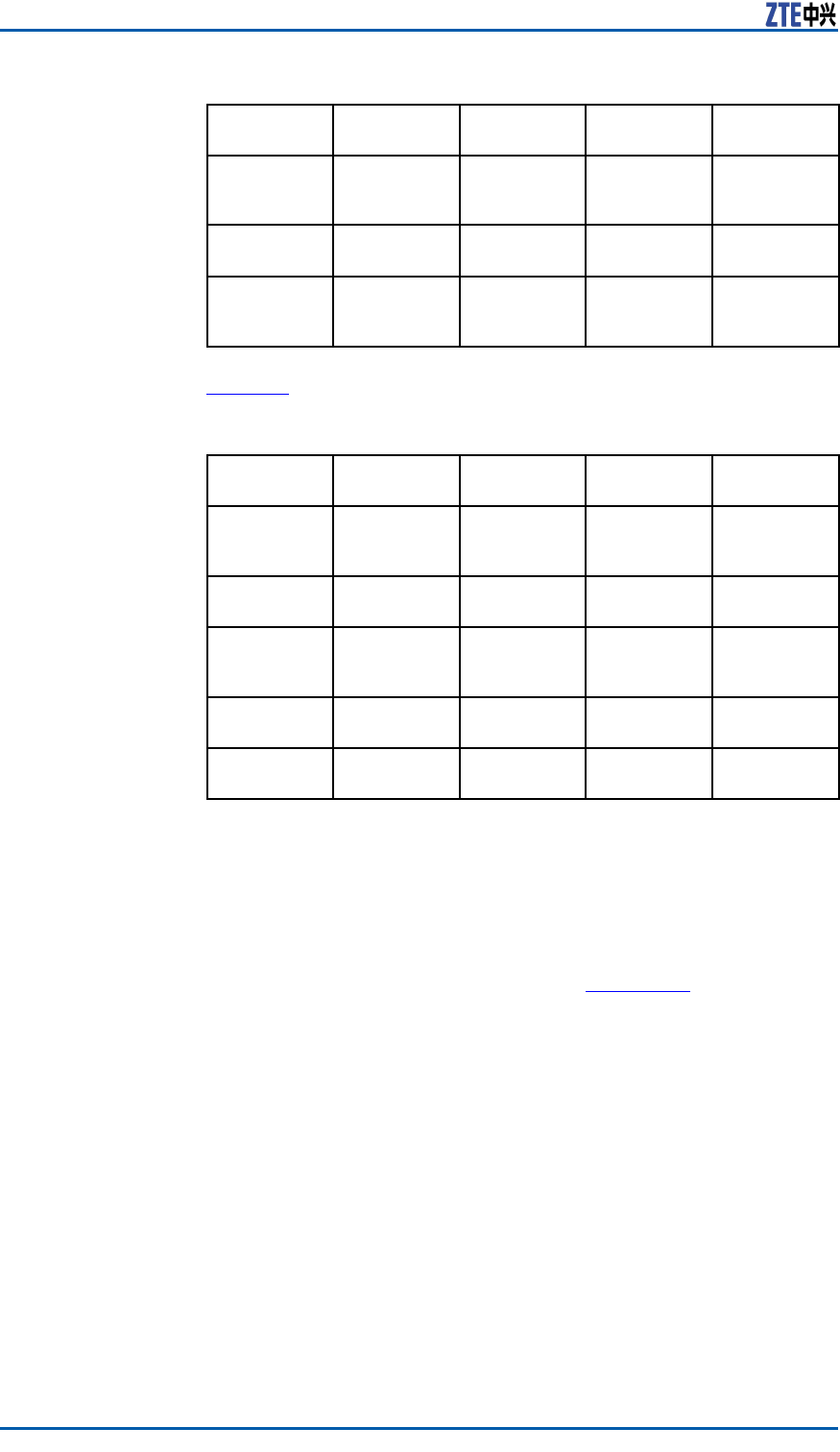
ZXSDRR8860InstallationManual
ItemUnit
Minimum
Value
Typical
Value
Maximum
Value
Startup
voltage
rangeVac150280
Inputfreq
uencyHz455065
Startup
impulse
currentA10
Table20describesoutputcharactersofOAU.
TABLE20OAUOUTPUTCHARACTERS
ItemUnit
Minimum
Value
Typical
Value
Maximum
Value
Output
voltage
rangeVdc-52-54-56
Output
currentA81012
Voltage
regulation
precision±2
Loadregula
tionrate±1
Output
powerW540
OAUAppearanceand
Interface
AppearanceTheappearanceofOAUisasshowninFigure100.
132ConfidentialandProprietaryInformationofZTECORPORATION
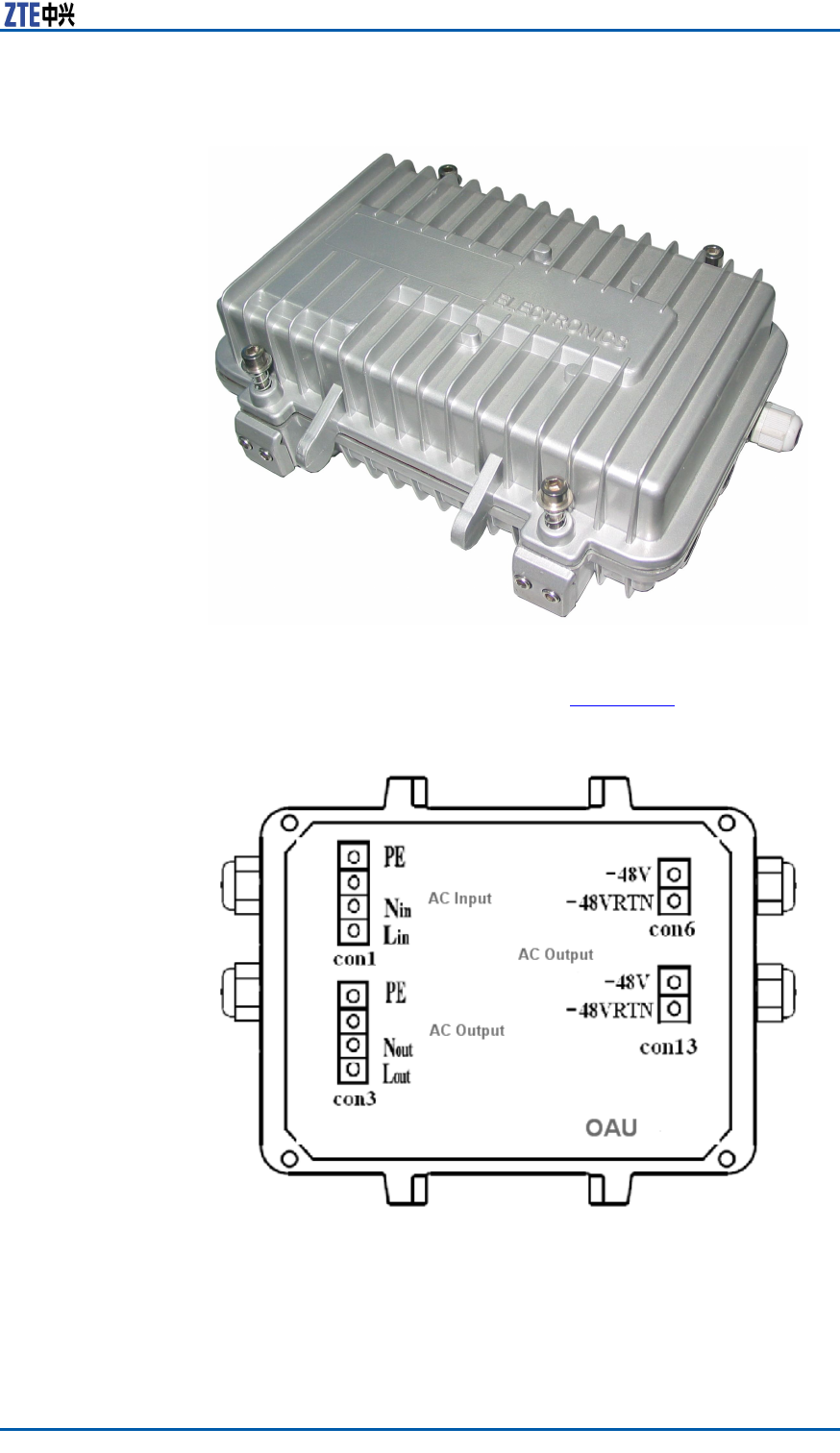
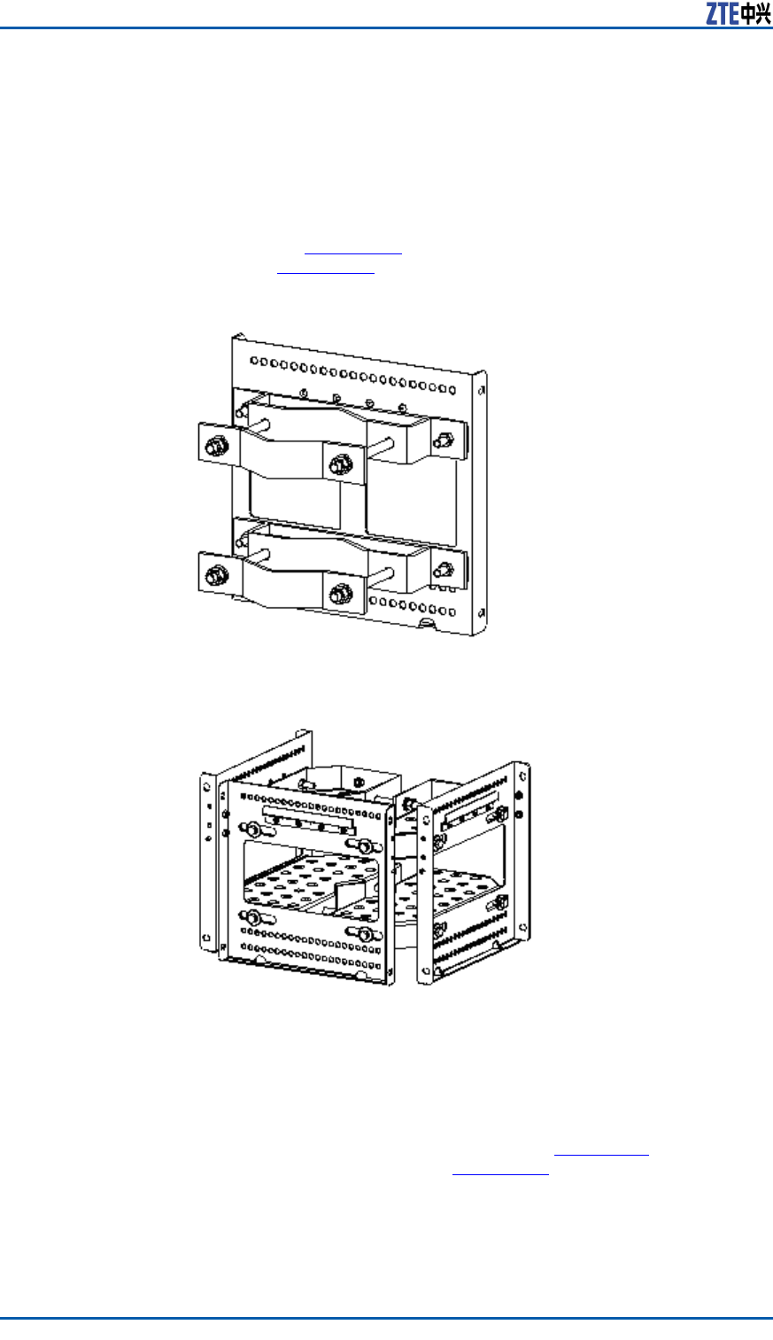
ZXSDRR8860InstallationManual
OAUPoleInstallation
PrerequisiteUnpackingandacceptanceforoutdoorACunit(OAU)isqualied.
ContextTheOAUpole-mountmodecanadoptanchorclampassemblies
orxingbracketassemblies.Theanchorclampassembliesare
asshowninFigure102andthexingbracketassembliesareas
showninFigure103.
FIGURE102ANCHORCLAMPASSEMBLIES
FIGURE103FIXINGBRACKETASSEMBLIES
Steps1.Installtheanchorclampassembliesorthexingbracketas-
semblies.
Installtwosetsofanchorclampassembliesortwosetsofxing
bracketsontothepoleandscrewdownabitwithbolts.The
anchorclampassembliesasshowninFigure104andthexing
bracketsareasshowninFigure105.
134ConfidentialandProprietaryInformationofZTECORPORATION
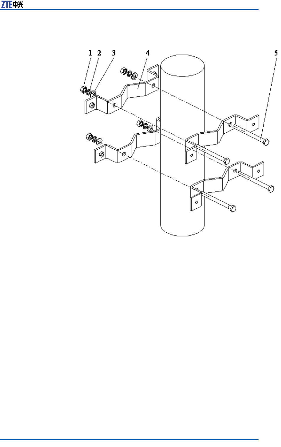
ChapterCOAU
FIGURE104TWOSETSOFANCHORCLAMPASSEMBLIES
1.I-typecommonM10hexago-
nalnut
2.Standardspringwasher10
3.Flatwasher10
4.Longanchorclamp
5.M10×120hexagonheadbolt
(fullthread)
ConfidentialandProprietaryInformationofZTECORPORATION135
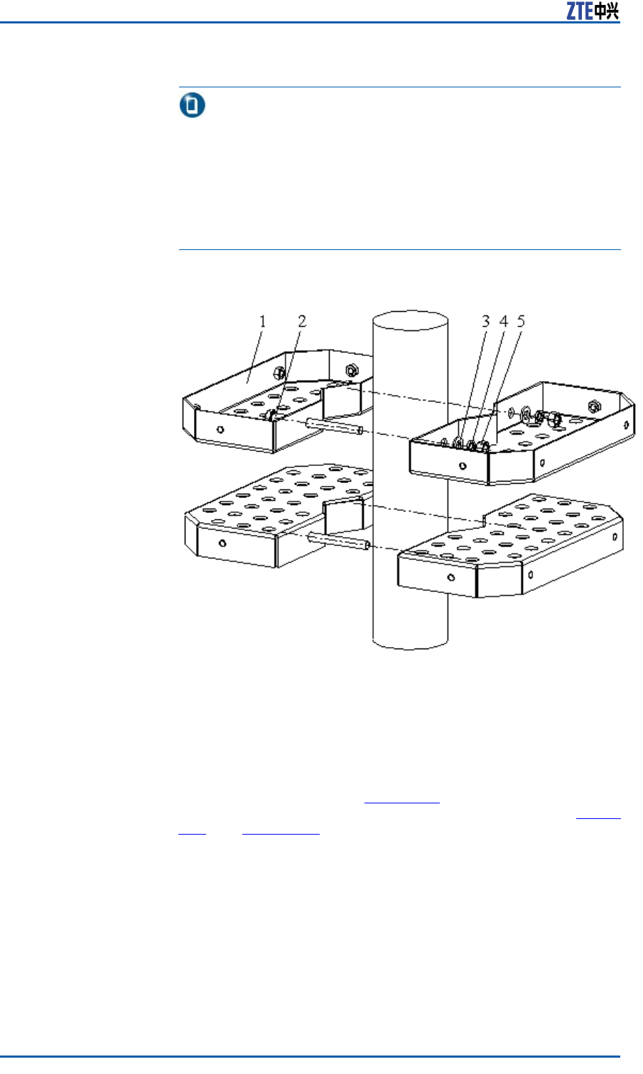
ZXSDRR8860InstallationManual
Tip:
DuringtwoZXSDRR8860installation,thesuggestedpoledi-
ameteris60to120mmandtherearetwokindsofboltlengths:
�Usetheboltoflength80mmforpolediameterof60mm
to90mm.
�Usetheboltoflength120mmforpolediameterof90mm
to120mm.
FIGURE105TWOSETSOFFIXINGBRACKETASSEMBLIES
1.FixingBracket
2.M10×120hexagonheadbolt
(fullthread)
3.Standardspringwasher10
4.Flatwasher10
5.I-typecommonM10hexago-
nalnut
2.InstallthebracketofOAU.
ThebracketisasshowninFigure106.Installthebracketsonto
thepoleinsteadofthesupportingpanelsasshowninFigure
107andFigure108.Screwdownthebrackets.
136ConfidentialandProprietaryInformationofZTECORPORATION
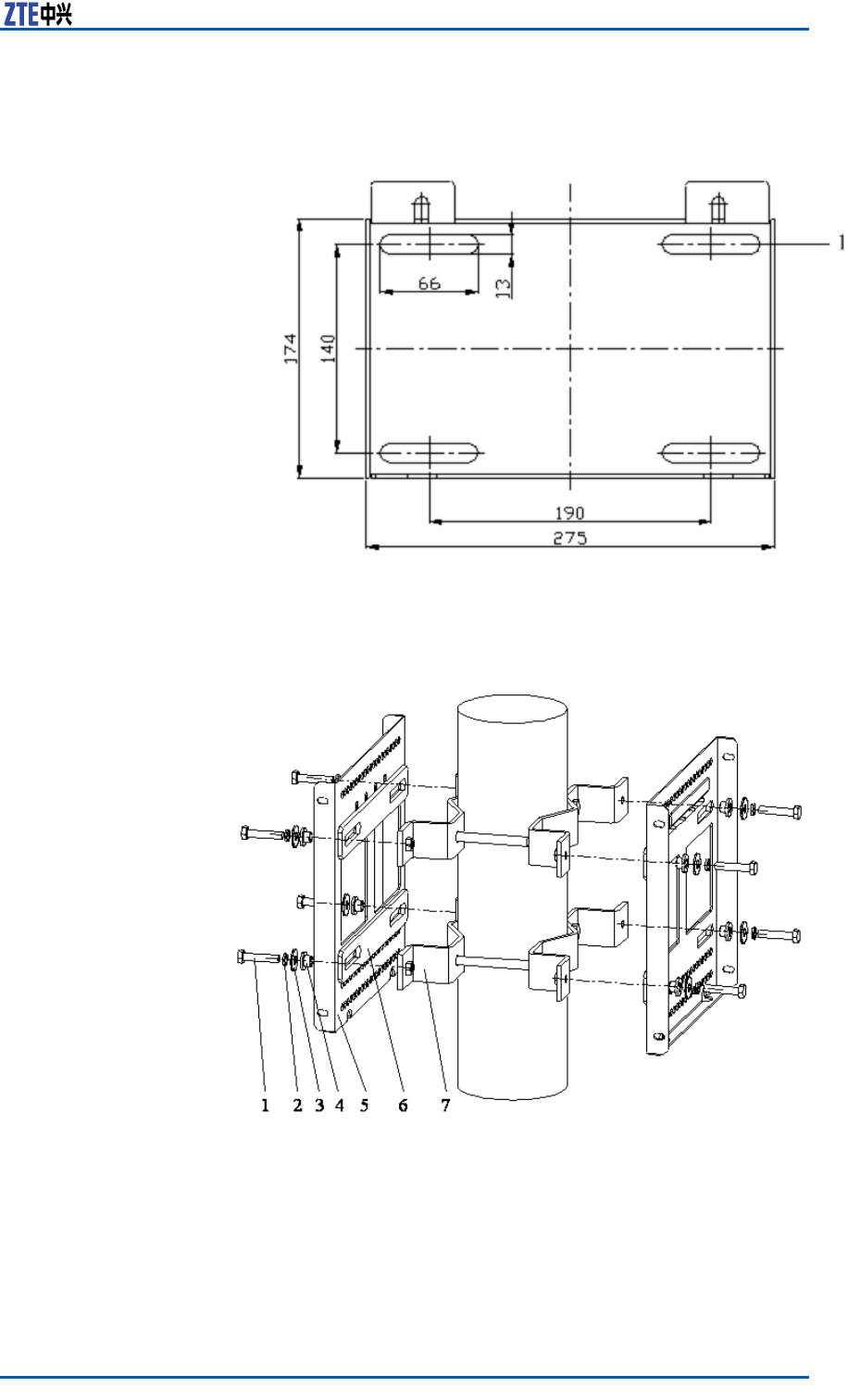
ChapterCOAU
FIGURE106OAUBRACKET
1.Installationpole
FIGURE107TWOSETSOFSUPPORTINGPANELS
1.M8×40hexagonheadbolt
2.Standardspringwasher8
3.Bigatwasher8
4.Insulationange
5.Supportingpanel
6.Insulationboard
7.Longanchorclamp
ConfidentialandProprietaryInformationofZTECORPORATION137
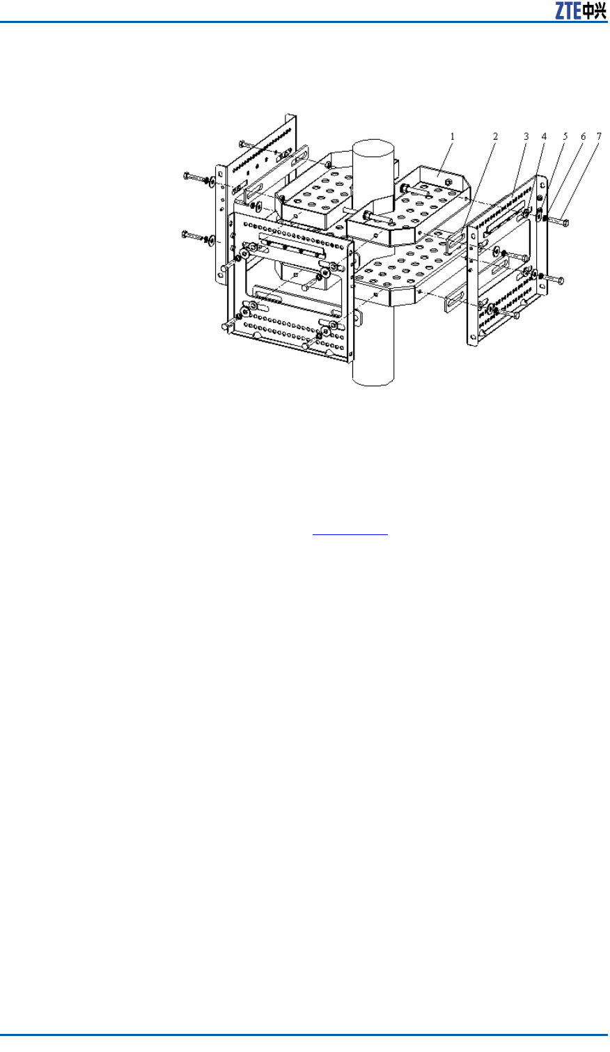
ZXSDRR8860InstallationManual
FIGURE108THREESETSOFSUPPORTINGPANELS
1.Fixingbracket
2.Insulationboard
3.Supportingpanel
4.Insulationange
5.Bigatwasher8
6.Standardspringwasher8
7.M8×40hexagonheadbolt
3.InstalltheOAU.
i.AsshownintheFigure109,fastentheOAUtothebrackets
withtheM6hexagonheadscrewsaccordingtothearrow-
headdirection.
138ConfidentialandProprietaryInformationofZTECORPORATION
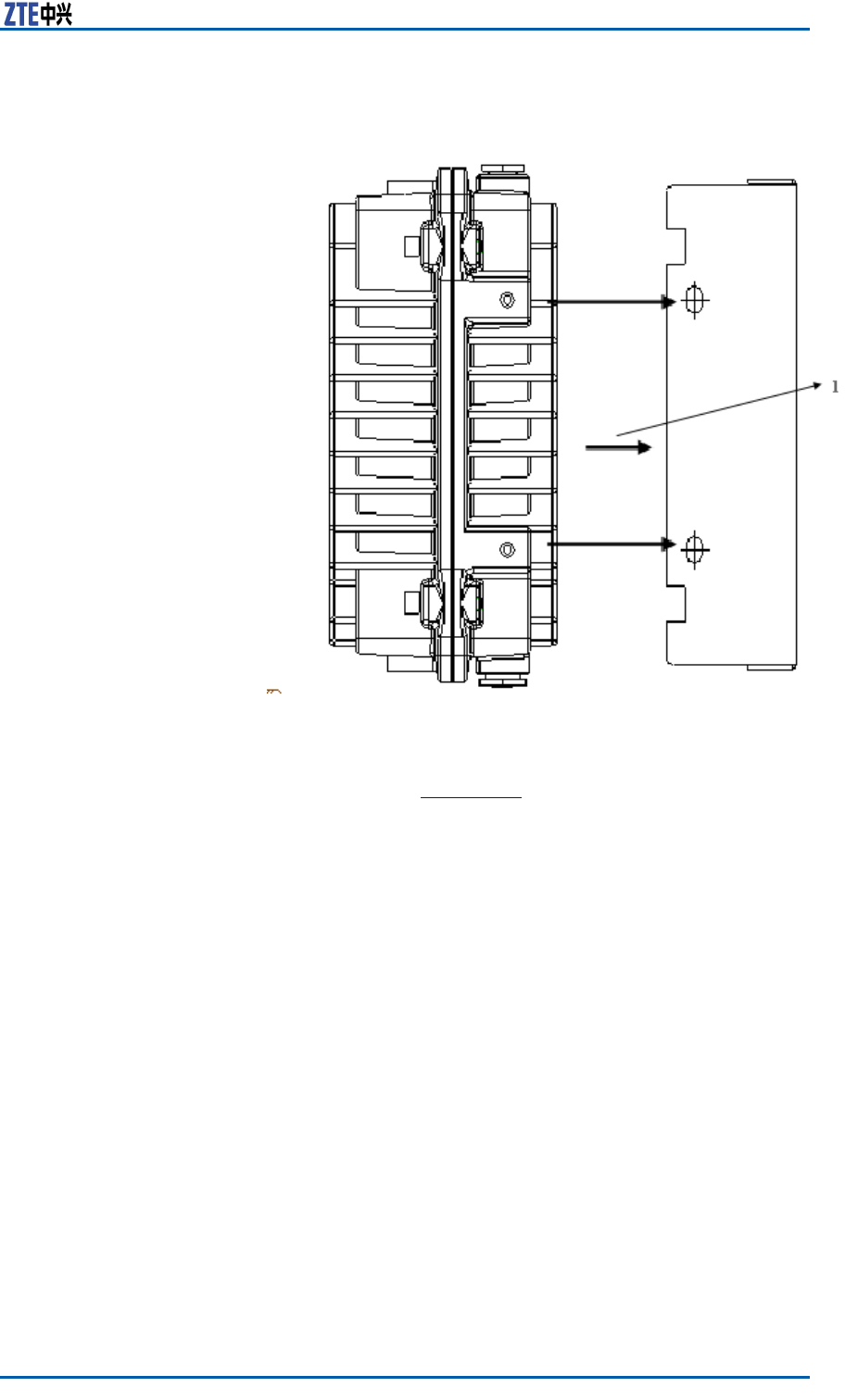
ChapterCOAU
FIGURE109OAUINSTALLATION(1)
1.Installationdirection
ii.AsshownintheFigure110,connecttheOAU,atwasher ,
springwasherandM8nutwiththeM8hexagonheadscrews
accordingtothearrowheaddirection.ScrewdowntheM8
nutatthebackofbracketinordertofastentheOAUand
thebracket.
ConfidentialandProprietaryInformationofZTECORPORATION139
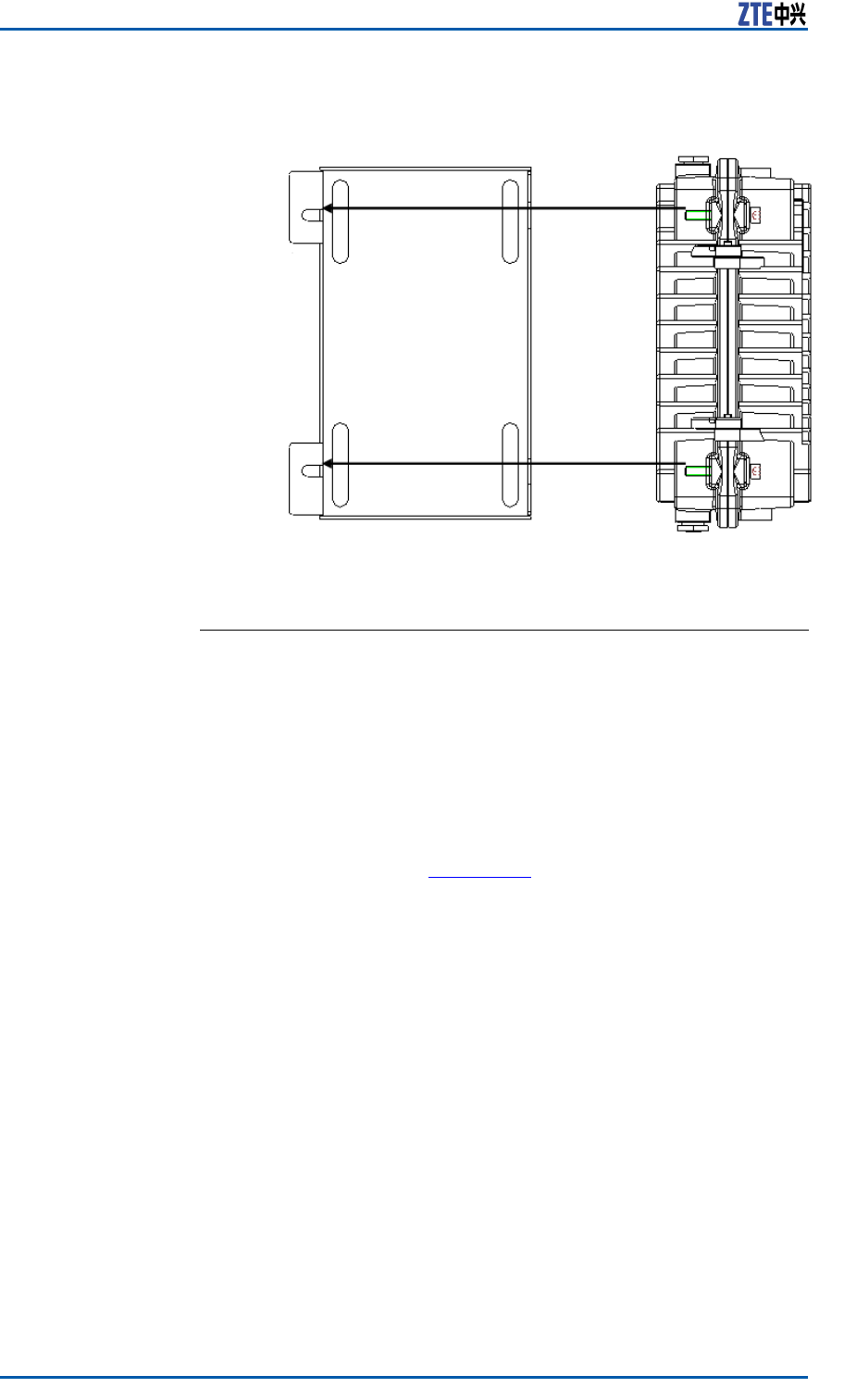
ZXSDRR8860InstallationManual
FIGURE110OAUINSTALLATION(2)
ENDOFSTEPS.
OAUOn-wallInstallation
PrerequisiteUnpackingandacceptanceforoutdoorACunit(OAU)isqualied.
Steps1.Installarack.
i.AsshownintheFigure111,drillholeswithM10drillon
thewallandknocktheM8expansionpipesintotheholes.
Makesuretheexpansionboltserectedwiththewall.
140ConfidentialandProprietaryInformationofZTECORPORATION
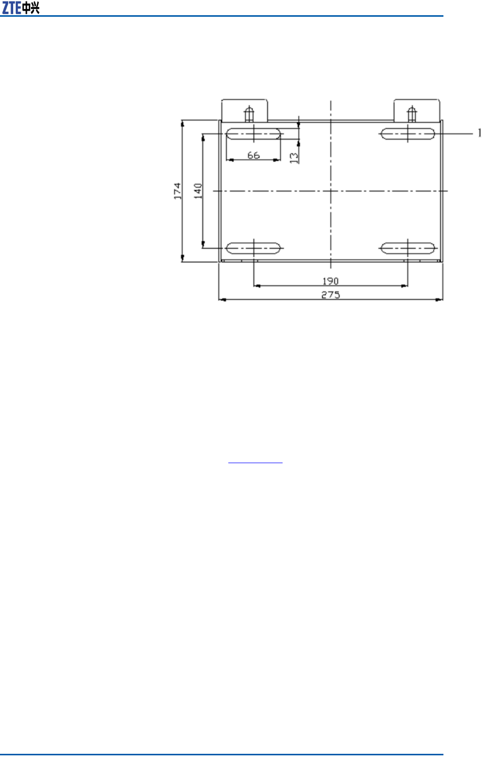
ChapterCOAU
FIGURE111OAURACK
1.Installationhole
ii.Aligninstallationholesonthebrackettoextensionpipes
onthewall.Afterhangingthebracket,rotatetheself-
drillingscrewassembledwithabigatwasherandaspring
washerintotheexpansionpipe.Screwdowntheboltwith
awrench.
2.InstalltheOAU.
i.AsshownintheFigure112,fastentheOAUtothebrackets
withtheM6hexagonheadscrewsaccordingtothearrow-
headdirection.
ConfidentialandProprietaryInformationofZTECORPORATION141
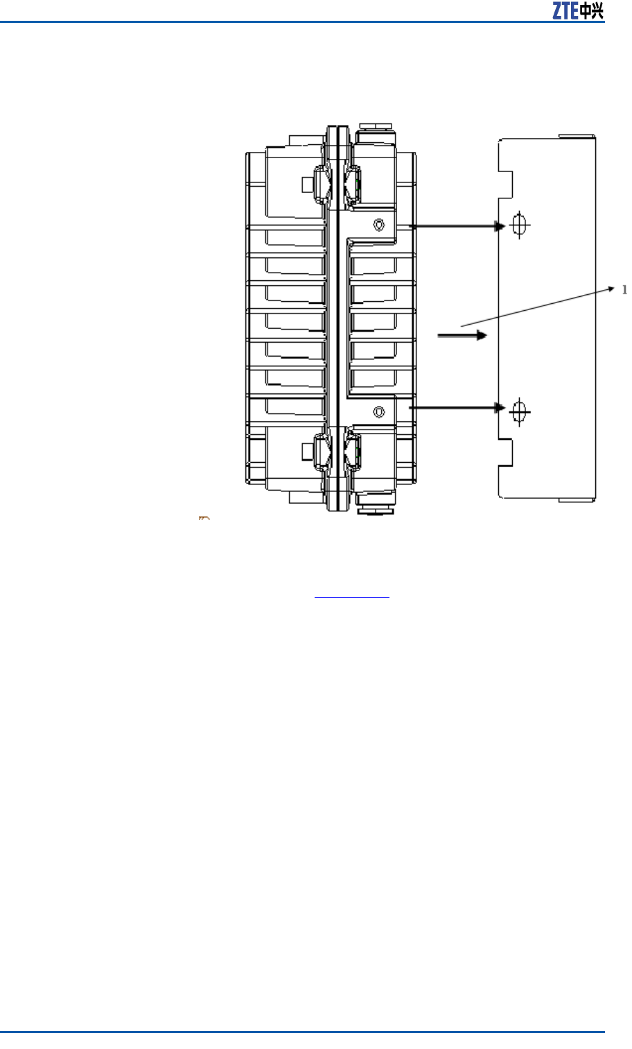
ZXSDRR8860InstallationManual
FIGURE112OAUINSTALLATION(1)
1.Installationdirection
ii.AsshownintheFigure113,connecttheOAU,atwasher ,
springwasherandM8nutwiththeM8hexagonheadscrews
accordingtothearrowheaddirection.ScrewdowntheM8
nutatthebackofbracketinordertofastentheOAUand
thebracket.
142ConfidentialandProprietaryInformationofZTECORPORATION
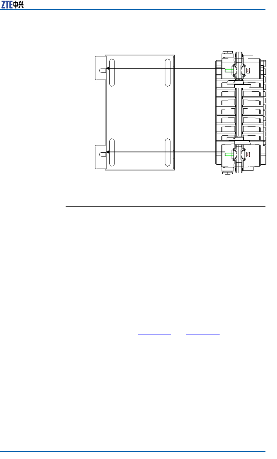
ChapterCOAU
FIGURE113OAUINSTALLATION(2)
ENDOFSTEPS.
OAUCableInstallation
PrerequisiteTheOAUinstallationiscompleted.
ContextTheOAUcanprovide-48VpowersupplyforoneZXSDRB8200
C100andoneZXSDRR8860C806atthesametime.
IftheOAUisinstalledoutsides,itisrequiredtocongureanAC
lightningbox.Forindoorinstallation,iftheACpowercableisdis-
tributedoutdoors,itisalsorequiredtocongureanAClightning
box.
Steps1.Installawaterproofendcap.
i.ReferringtotheFigure114andFigure115,loosenoffthe
waterproofendcap.
ConfidentialandProprietaryInformationofZTECORPORATION143
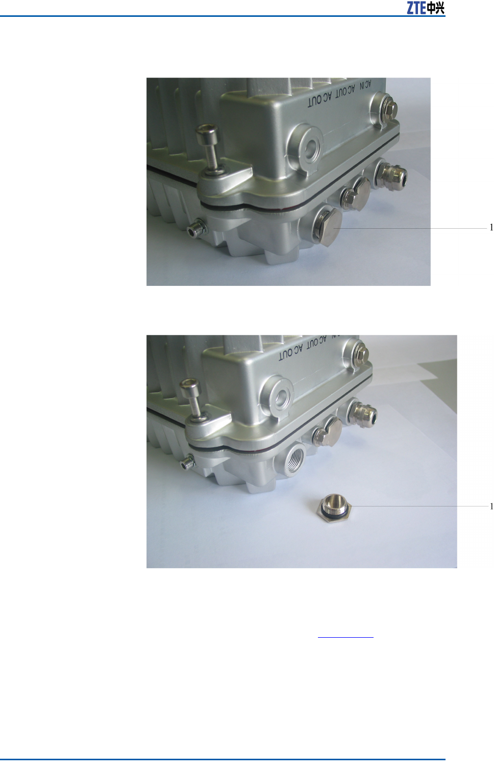
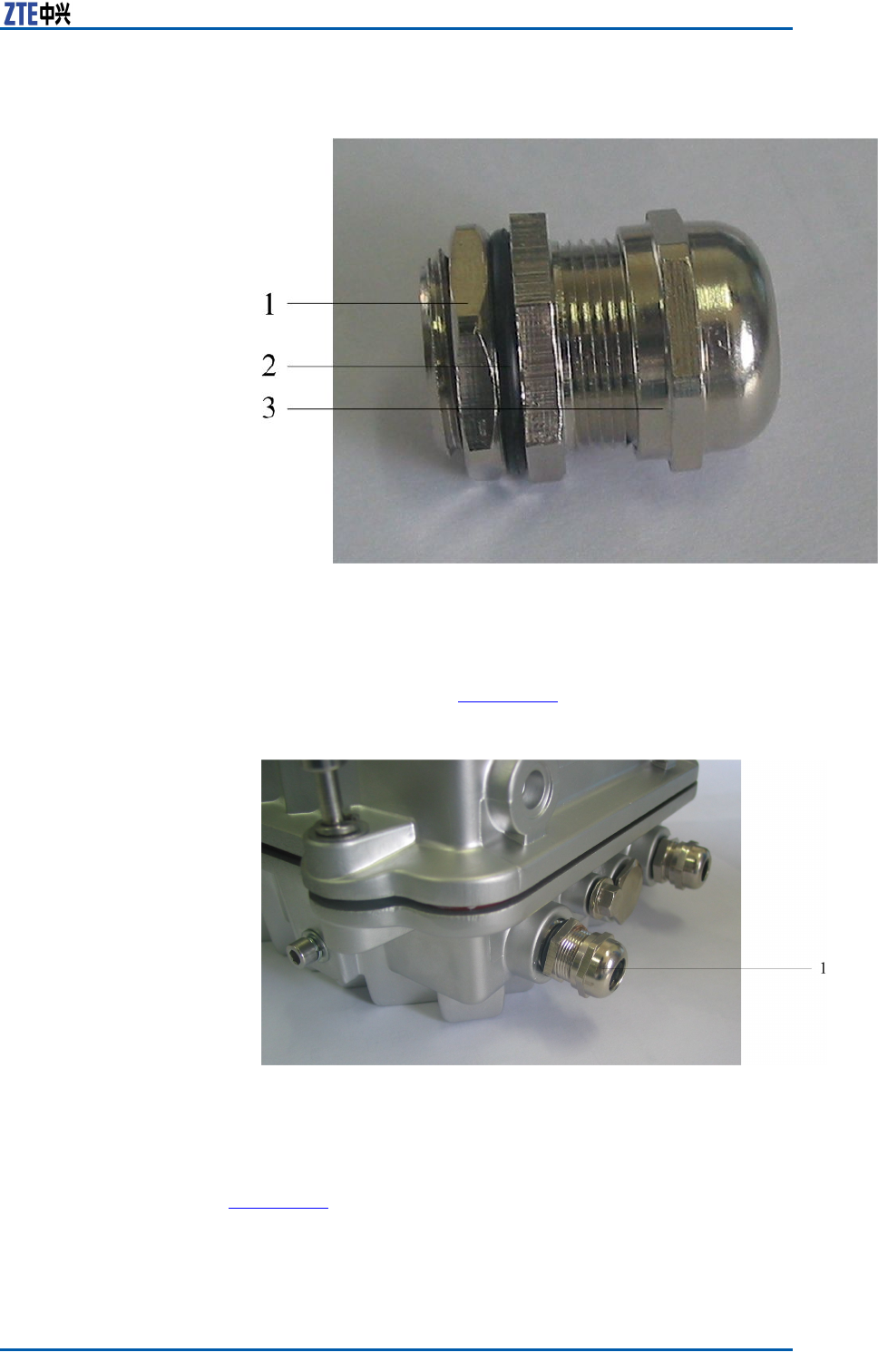
ChapterCOAU
FIGURE116WATERPROOFENDCAPSTRUCTURE
1.Nut
2.Waterproofring
3.Waterproofendcap
iii.InstallthewaterproofendcapontotheOAUandscrew
downit,asshowninFigure117.
FIGURE117WATERPROOFENDCAPINSTALLATION
1.Waterproofendcap
2.DisassembletheOAUandconnecttheACpowercablewiththe
DCpowercable.TheconnectionofACcableisasshownin
Figure118.
ConfidentialandProprietaryInformationofZTECORPORATION145
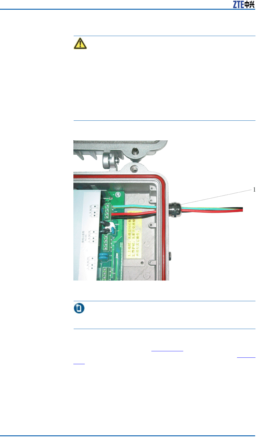
ZXSDRR8860InstallationManual
Caution:
1.WhileconnectingtheACpowercable,rstconnectthePE
cable,NcableandLcable.Fordisconnecting,thesequence
isopposite,rsttheLcable,NcableandnallyPEcable.
2.Beforepoweron,rstconrmthePEcablegroundingwell.
Duringmaintenance,rstdisconnecttheACinputandthen
performotheroperation.
3.Aftercutoffthepower ,waitforfourminutesatleastuntil
thecapacitydischargeenoughandthenperformmainte-
nanceoperationfortheOAU.
FIGURE118ACPOWERCABLECONNECTION
1.Waterproofendcap
Note:
Thecablecolordecidesonsite.
3.ConnectoneAClightningbox,threeOAUsandthreeZXSDR
R8860C806,asshowninFigure119.Fortheconnectionbe-
tweenOAUandZXSDRB8200C100,pleaserefertotheFigure
119.
146ConfidentialandProprietaryInformationofZTECORPORATION
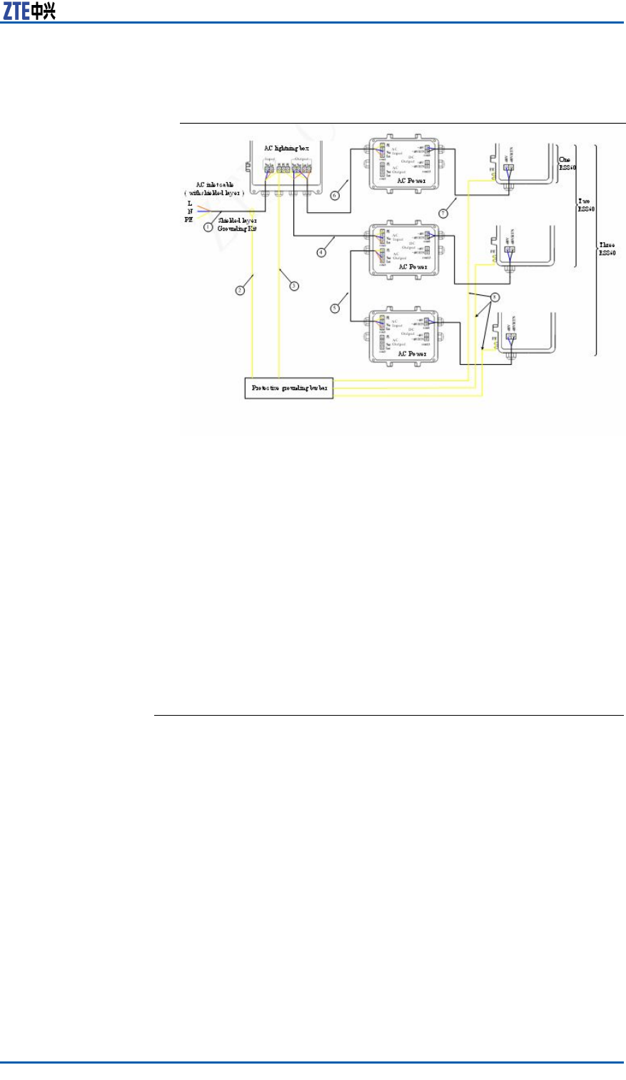
ChapterCOAU
FIGURE119ONEACLIGHTNINGBOX,THREEOAUSANDTHREE
R8860CABLECONNECTION
1.ACpowercable(Foroutdoor
installation,three-coreout-
dooraluminum-foilshielding
powercable;forindoorin-
stallation,PVCsheathpower
cable;thecablelengthde-
pendsonsurveyonsite.)
2.Groundingcableofgrounding
kit(with1.5mlong)
3.Groundingcable(yellow-and-
greenre-retardantcable;
thelengthislessthan1m)
4.ACpowercable(three-core
outdooraluminum-foilshield-
ingpowercable;thecable
lengthdependsonsurveyon
site.)
5.ACpowercable(three-core
outdooraluminum-foilshield-
ingpowercable;thecable
lengthdependsonsurveyon
site.)
6.ACpowercable(three-core
outdooraluminum-foilshield-
ingpowercable;thecable
lengthdependsonsurveyon
site.)
7.DCpowercable(four-core,
with2mlong)
8.Groundingcable(yellow-and-
greenre-retardantcable;
thelengthislessthan1m)
ENDOFSTEPS.
ConfidentialandProprietaryInformationofZTECORPORATION147

ZXSDRR8860InstallationManual
Thispageisintentionallyblank.
148ConfidentialandProprietaryInformationofZTECORPORATION

AppendixD
OLP48-2
TableofContents:
OLP48-2T echnicalIndices.......................................................149
OLP48-2AppearanceandInterface...........................................149
OLP48-2InstallationDescription...............................................151
OLP48-2TechnicalIndices
TheoutdoorDClightningbox(OLP48–2)isusedforsurgeprotec-
tionofZXSDRR8860.Thefollowingdescribesitscharacters:
�Adoptprotectivecircuitfortwoports,withlowresidualvoltage
andgoodprotectiveperformance.
�Adoptthetemperature-controlbroken-circuittechnologyto
avoidrehazards.
�Adoptpressure-sensitiveparallelconnectiontoenduresustain-
inglightningstrike.
�Adoptanalarmreportfunctionforremotemonitoring.
Engineering
TechnicalIndices
Table21describestheengineeringtechnicalindicesofoutdoorDC
lightningbox.
TABLE21ENGINEERINGTECHNICALINDICES
ItemIndex
DimensionH×W×D:297mm×220mm×90mm
Nominalworkvoltage–48VDC
Maximumcontinuous
runningvoltage
–75VDC
Worktemperature-40℃+65℃
Workhumidity10%RH~95%RH25℃
OLP48-2Appearanceand
Interface
AppearanceFigure120showstheappearanceofoutdoorDClightningbox.
ConfidentialandProprietaryInformationofZTECORPORATION149
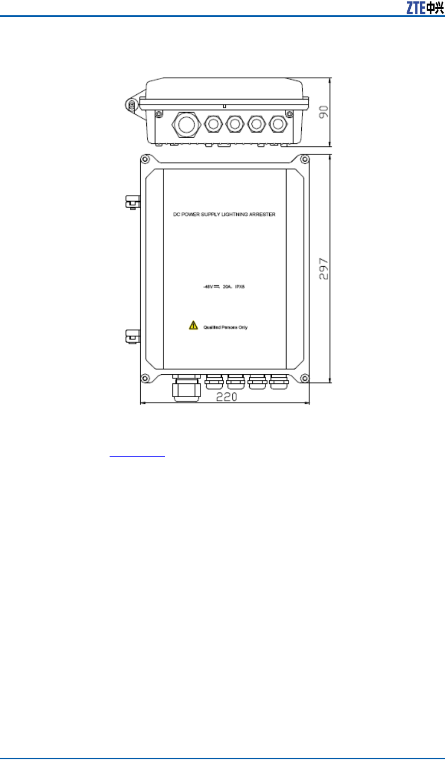
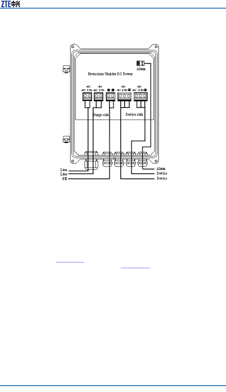
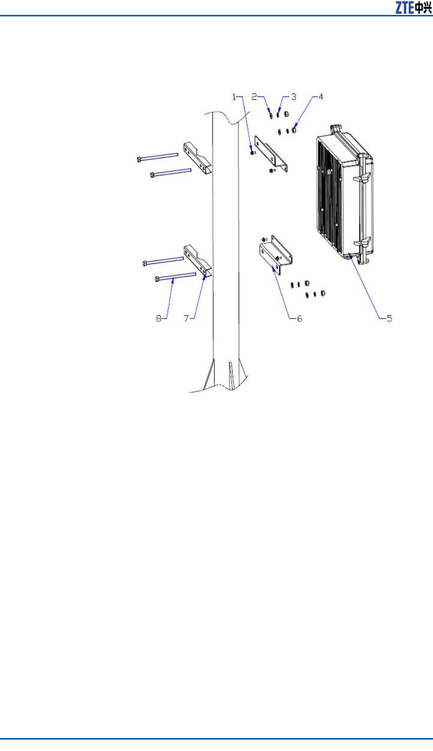
ZXSDRR8860InstallationManual
FIGURE122INSTALLATIONPARTS
1.CombinedboltM4×10
2.Plainwasher8
3.Springwasher8
4.NutM8
5.OutdoorDClightningbox
6.OLPMsupport(1)
7.OLPMsupport(2)
8.HexagonboltM8×140
152ConfidentialandProprietaryInformationofZTECORPORATION
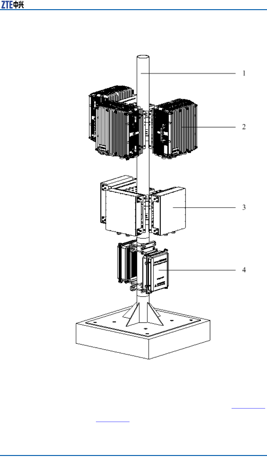
ChapterDOLP48-2
FIGURE123OUTDOORDCLIGHTNINGPOLEINSTALLATION
1.Pole
2.ZXSDRR8841C804
3.Wavetrap
4.OutdoorDClightningbox
CableConnectionT akeapartacabinetandconnectcablesasshowninFigure124.
ConnectoneoutdoorDClightningboxwithone(ortwo)RRU,as
showninFigure125.
ConfidentialandProprietaryInformationofZTECORPORATION153
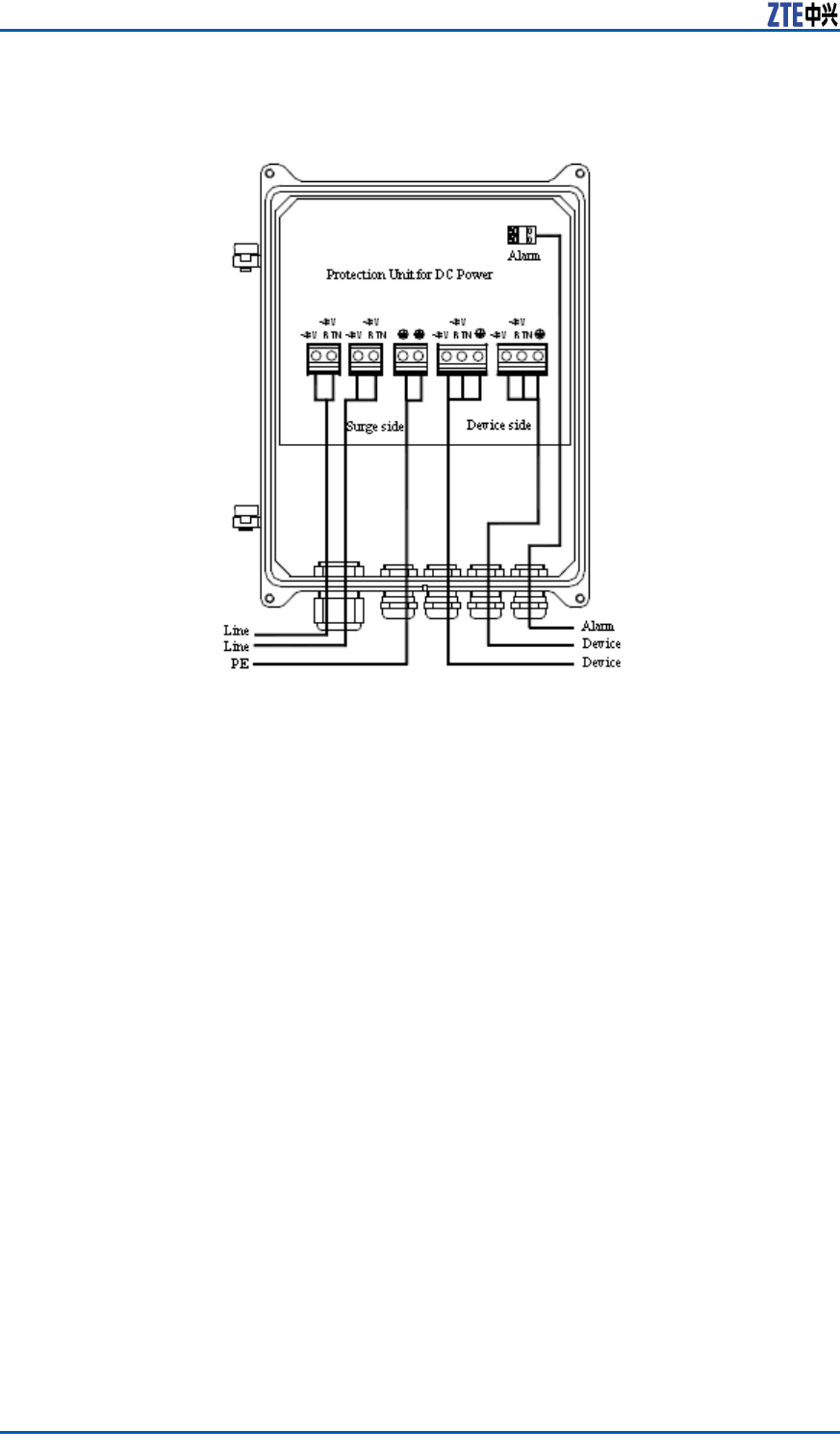
ZXSDRR8860InstallationManual
FIGURE124OUTDOORDCLIGHTNINGBOXINTERFACES
154ConfidentialandProprietaryInformationofZTECORPORATION
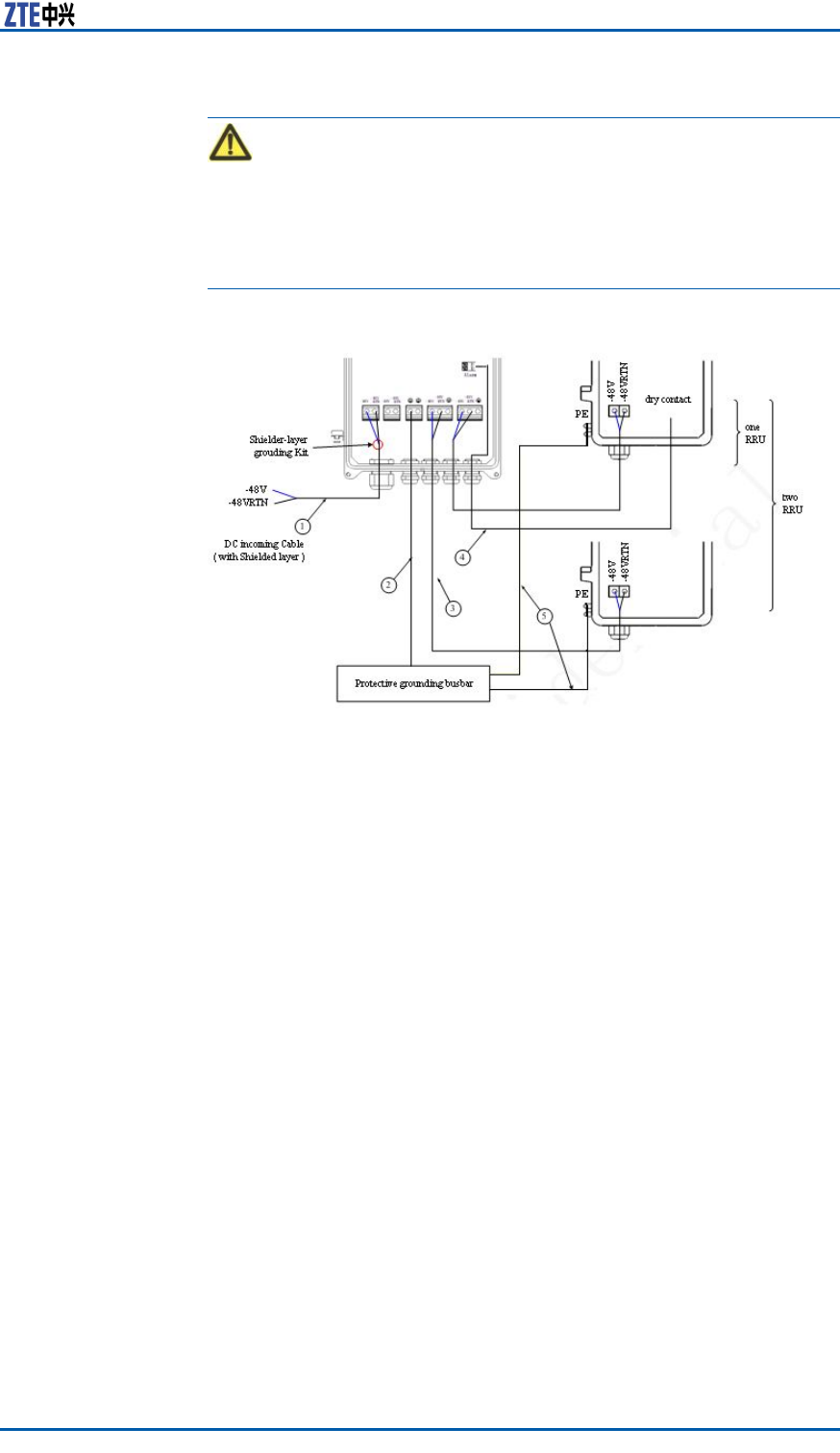
ChapterDOLP48-2
Caution:
1.Whileconnectingcablesoflightningbox,itisrequiredtoput
thecablethroughtheholeofwaterproofconnectoratthebot-
tomofbox.
2.Firstconnectthegroundcablesandthenconnectothercables.
Whiledisconnecting,nallyremovethegroundcable.
FIGURE125OUTDOORDCLIGHTNINGCONNECTION
1.DCpowercable(two-coreoutdoor
shieldedpowercable;theshielded
layerisgroundinginsidethelight-
ingbox;thecablelengthdepends
ontheon-sitesurvey)
2.Groundingcable(yellow-and-
greenre-retardantcable;the
lengthislessthan1m)
3.DCpowercable(four-corewith2
mlong)
4.Datacable(eight-pairtwisted-pair
outdoordatacablewith3mlong)
5.Groundingcable(yellow-and-
greenre-retardantcable;the
lengthislessthan1.5m)
ConfidentialandProprietaryInformationofZTECORPORATION155

ZXSDRR8860InstallationManual
Thispageisintentionallyblank.
156ConfidentialandProprietaryInformationofZTECORPORATION

AppendixE
ILP48-3
TableofContents:
ILP48-3T echnicalIndices........................................................157
ILP48-3AppearanceandInterface............................................158
ILP48-3InstallationDescription................................................159
ILP48-3TechnicalIndices
ForZXSDRR8860outdoorinstallation,iftheDCpowerisexported
fromtheequipmentroomandtheoutputportofindoorDCpower
isnotconguredwithaB-levelorabovelightningdevices,itis
requiredtoinstallanindoorDClightingbox(ILP48–3)attheside
ofequipmentroom.
TheindoorDClightningboxcontainsthreeindividualDC-48VDC
lightnings.Theircharactersaredescribedasfollows:
1.Adoptthetemperature-controlbroken-circuittechnologyto
avoidrehazards.
2.Adoptanalarmreportfunctionforremotemonitoring.
3.Adoptdouble-colorindicatorstodirectlyandclearlyindicate
workingstatus
Engineering
TechnicalIndices
Table22describestheengineeringtechnicalindicesofindoorDC
lightningbox.
TABLE22ENGINEERINGTECHNICALINDICES
ItemIndex
DimensionH×W×D:450mm×400mm×100mm(not
includetheheightoflockontheupper
cover)
Nominalworkvoltage–48VDC
Maximumcontinuous
runningvoltage
–75VDC
Worktemperature-5℃+70℃
Workhumidity≤95%RH
ConfidentialandProprietaryInformationofZTECORPORATION157
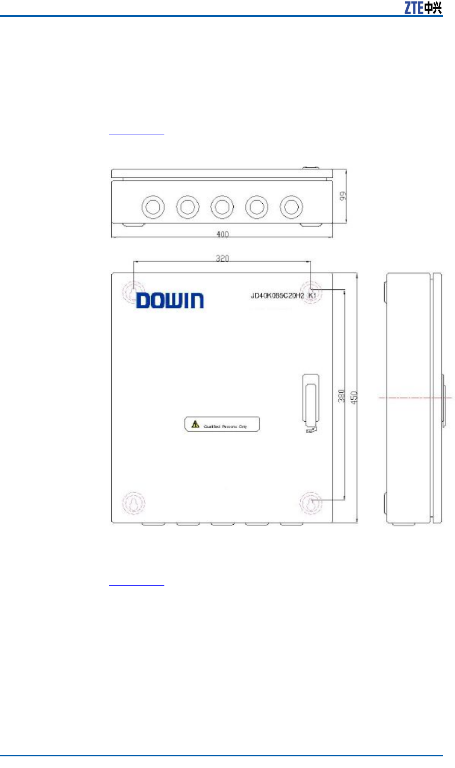
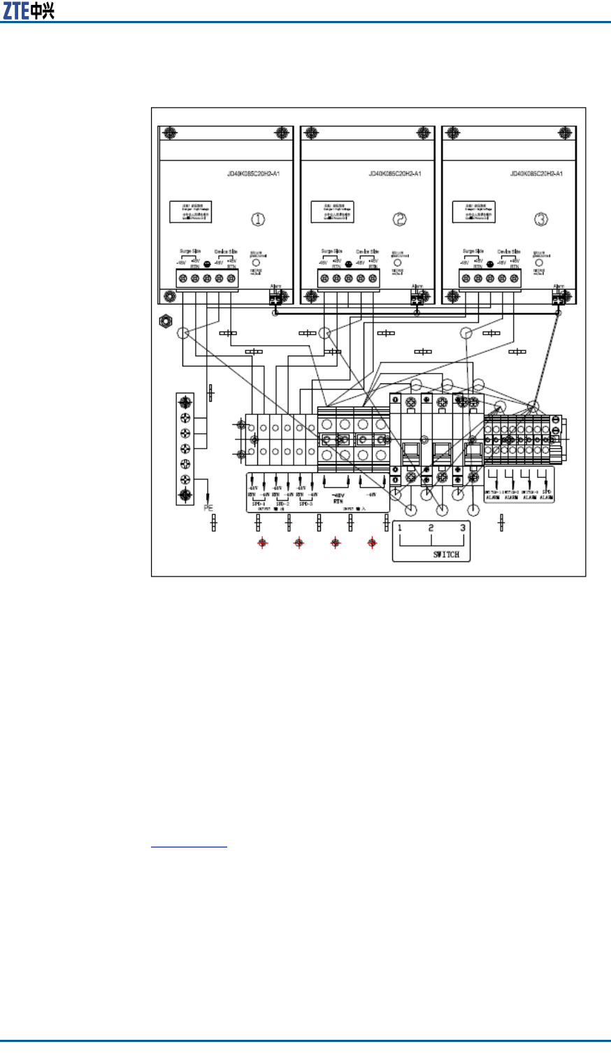
ChapterEILP48-3
FIGURE127INDOORDCLIGHTNINGBOXINTERFACES
ILP48-3Installation
Description
InstallationTheindoorDClightingboxadoptsanon-wallinstallationmode.
Drillholeonthewallofequipmentroomaccordingtoinstallation
polepositionsonthelightningbox.SelectfourM6×60(ormore
longer)expansionboltstofastenthelightningboxonthewall.
CableConnectionFigure128illustratescableconnectionoflightningbox.
ConfidentialandProprietaryInformationofZTECORPORATION159
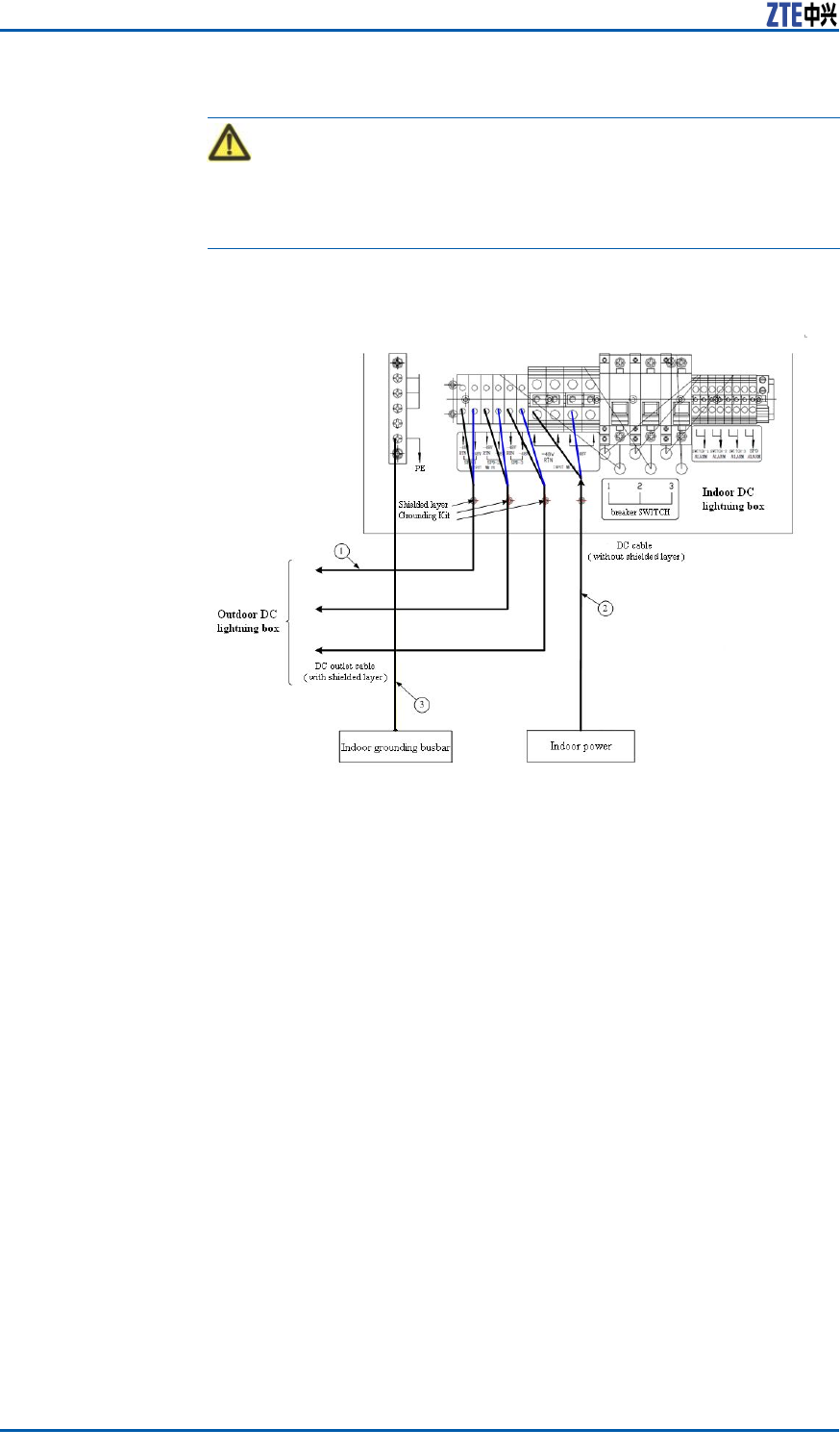
ZXSDRR8860InstallationManual
Caution:
Firstconnectthegroundingcableandthenothercables.While
disconnecting,nallyremovethegroundingcable.
FIGURE128INDOORDCLIGHTNINGBOXCABLECONNECTION(NOT
CONNECTWITHREMOTEALARM)
1.DCpowercable(two-coreoutdoor
shieldedpowercable;theshielded
layerisgroundinginsidethelight-
ingbox;thecablelengthdepends
ontheon-sitesurvey)
2.DCpowercable(two-coreoutdoor
shieldedpowercable;thecable
lengthdependsontheon-sitesur-
vey)
3.Groundingcable(yellow-and-
greenre-retardantcable;the
lengthislessthan1.5m)
160ConfidentialandProprietaryInformationofZTECORPORATION

AppendixF
ACLightningArrester
TableofContents:
ACLightningTechnicalIndices..................................................161
ACLightningAppearanceandInterface.....................................162
ACLightningInstallationDescription.........................................163
ShieldedGroundingKitInstallation...........................................168
ACLightningTechnical
Indices
TheprotectivecircuitofAClightningconsistsofpowerprotection
andsignalprotection,respectivelyusedforlightningsurgeprotec-
tionofsupplypowerandcircuitinterface.
Thecharactersofpowerprotectionaredescribedasfollows:
�Adoptseriesprotectivecircuit,withlowresidualvoltageand
goodprotectiveperformance.
�Adoptthetemperature-controlbroken-circuittechnologyto
avoidrehazards.
�Adoptpressure-sensitiveparallelconnectiontoenduresustain-
inglightningstrike.
Thecharactersofsignalprotectionaredescribedasfollows:
�Largedischargecurrent
�Lowresidualvoltageandgoodprotectiveperformance
�Eightsignalprotectioncircuits
Engineering
TechnicalIndices
Table23describestheengineeringtechnicalindicesofAClightning
box.
TABLE23ENGINEERINGTECHNICALINDICES
ItemIndex
DimensionH×W×D:297mm×220mm×90mm
Ratingworkvoltage110/220~240VAC50/60Hz
Maximumcontinuous
runningvoltage
385VAC
Worktemperature-40℃+70℃
ConfidentialandProprietaryInformationofZTECORPORATION161
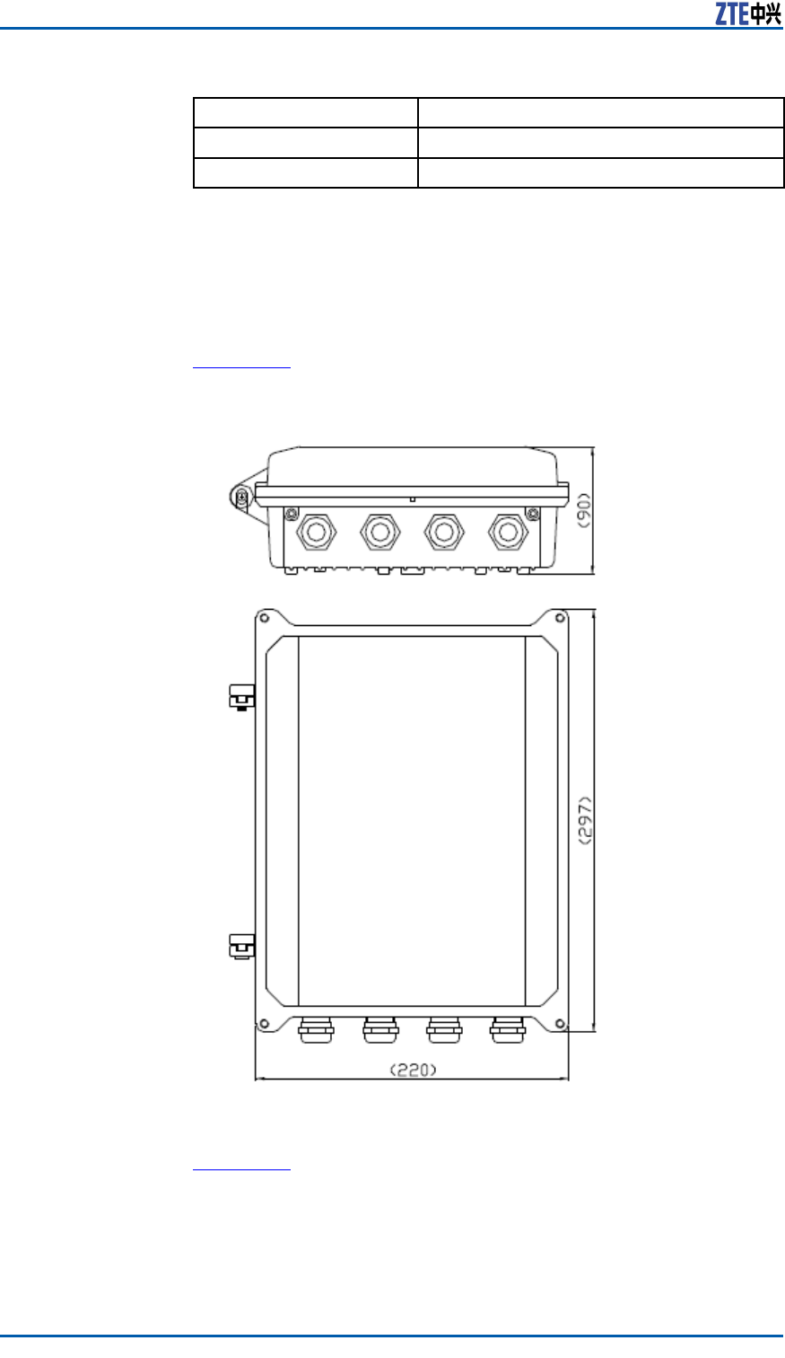
ZXSDRR8860InstallationManual
ItemIndex
Workhumidity10%RH~95%RH25℃
Altitude≤3000m
ACLightningAppearance
andInterface
AppearanceFigure129illustratestheappearanceofAClightningbox.
FIGURE129ACLIGHTNINGBOXAPPEARANCE
InterfaceFigure130illustratestheinterfacesofAClightningbox.
162ConfidentialandProprietaryInformationofZTECORPORATION
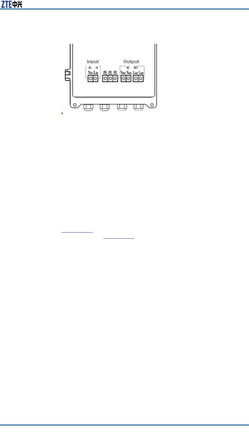
ChapterFACLightningArrester
FIGURE130ACLIGHTNINGBOXINTERFACE
ACLightningInstallation
Description
WhentheZXSDRR8841C804isinstalledoutsides,itisrequiredto
congureAClightningboxforACpowersupply.WhentheZXSDR
R8860C806isinstalledoutsides,itisrequiredtocongureAC
lightningboxatthefrontofoutdoorACunit(OAU)forindirectAC
powersupply.
InstallationFigure131illustratespartstoprovideforpoleinstallationofAC
lightningbox.Figure132showstheappearanceafterinstallation
completion.
ConfidentialandProprietaryInformationofZTECORPORATION163
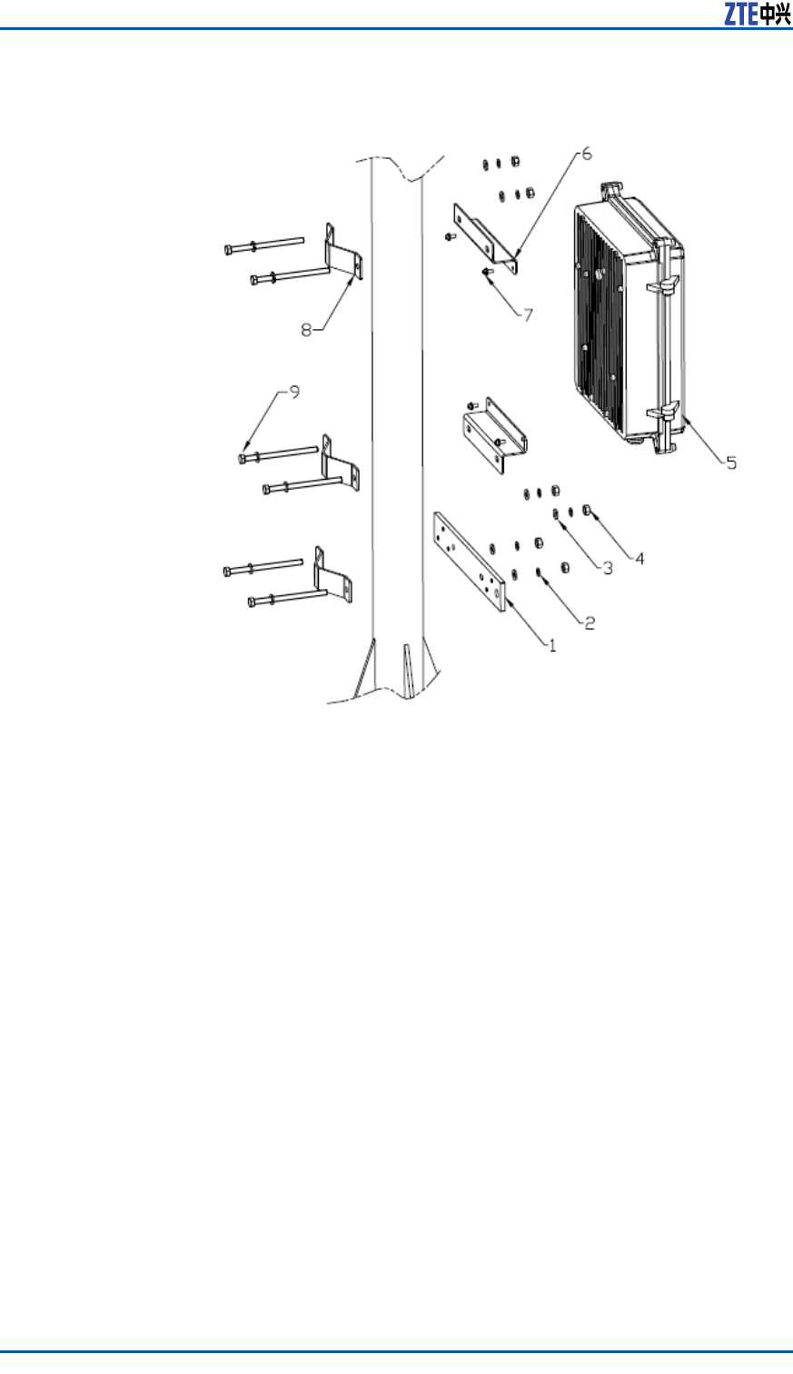
ZXSDRR8860InstallationManual
FIGURE131ACLIGHTNINGBOXINSTALLATIONPARTS
1.Groundingcopperbar
2.SpringwasherM6
3.FlatwasherM6
4.NutM6
5.AClightningbox
6.Installationsupport
7.CombinedboltM4×10
8.Fastener
164ConfidentialandProprietaryInformationofZTECORPORATION
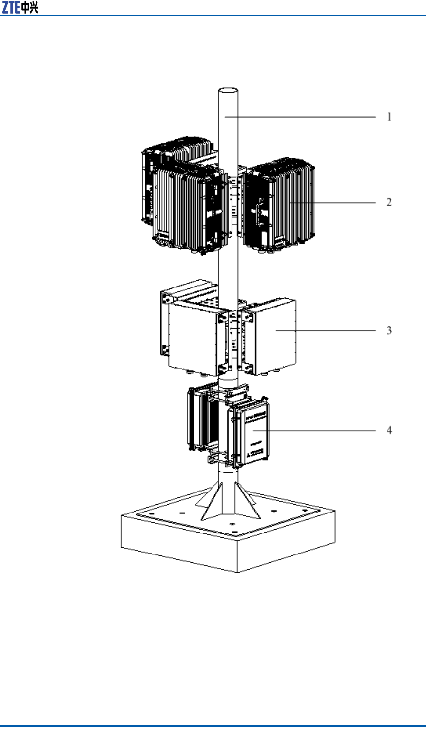
ChapterFACLightningArrester
FIGURE132ACLIGHTNINGPOLEINSTALLATION
1.Pole
2.ZXSDRR8841C804
3.Wavetrap
4.AClightningbox
CableConnectionUnpackacabinetandconnectcables.
ConfidentialandProprietaryInformationofZTECORPORATION165
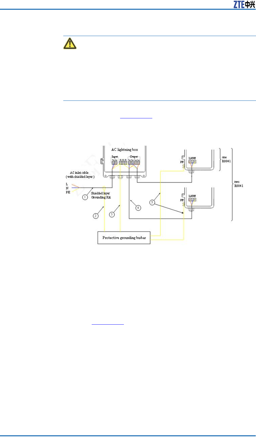
ZXSDRR8860InstallationManual
Caution:
1.Firstconnectthegroundingcableandthenothercables.While
disconnecting,nallyremovethegroundingcable.
2.Thecabletoconnectthelightningboxmustbeputthrougha
holeofwaterproofconnectoratthebottomofbox.
3.Afterconnectioncompletedandchecked,screwdownallwa-
terproofconnectorsandwrapwaterproofconnectorsandca-
bleswithwaterproofadhesivetape.
ConnectoneAClightningboxwithone(ortwo)ZXSDRR8841
C804,asshowninFigure133.
FIGURE133ONEACLIGHTNINGBOXANDONE(ORTWO)R8841CABLE
CONNECTION
1.ACpowercable(three-coreout-
doorbraidandaluminumfoil
shieldingcable;thecablelength
dependsonon-sitesurvey)
2.Groundingkitgroundingcable
(two-corepowercablewith1.5m
long)
3.Groundingcable(yellow-and-
greenre-retardantcable;the
lengthislessthan1.5m)
4.ACpowercable(softcableandthe
lengthdependsonon-sitesurvey)
5.Groundingcable(yellow-and-
greenre-retardantcable;the
lengthislessthan1.5m)
ConnecttwoAClightningboxwiththreeZXSDRR8841C804,as
showninFigure134.
166ConfidentialandProprietaryInformationofZTECORPORATION
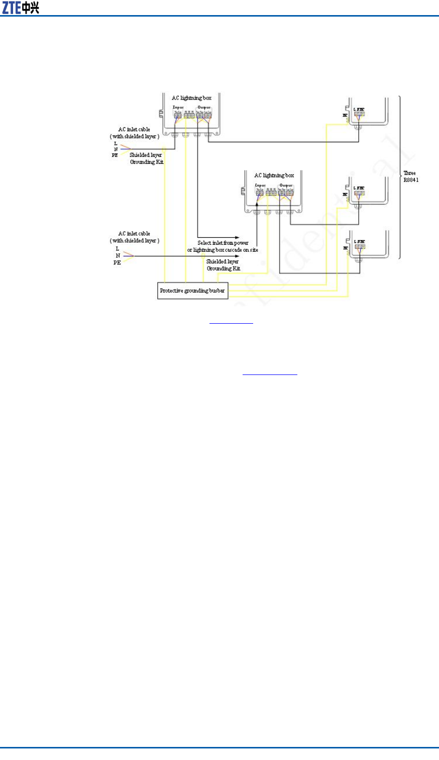
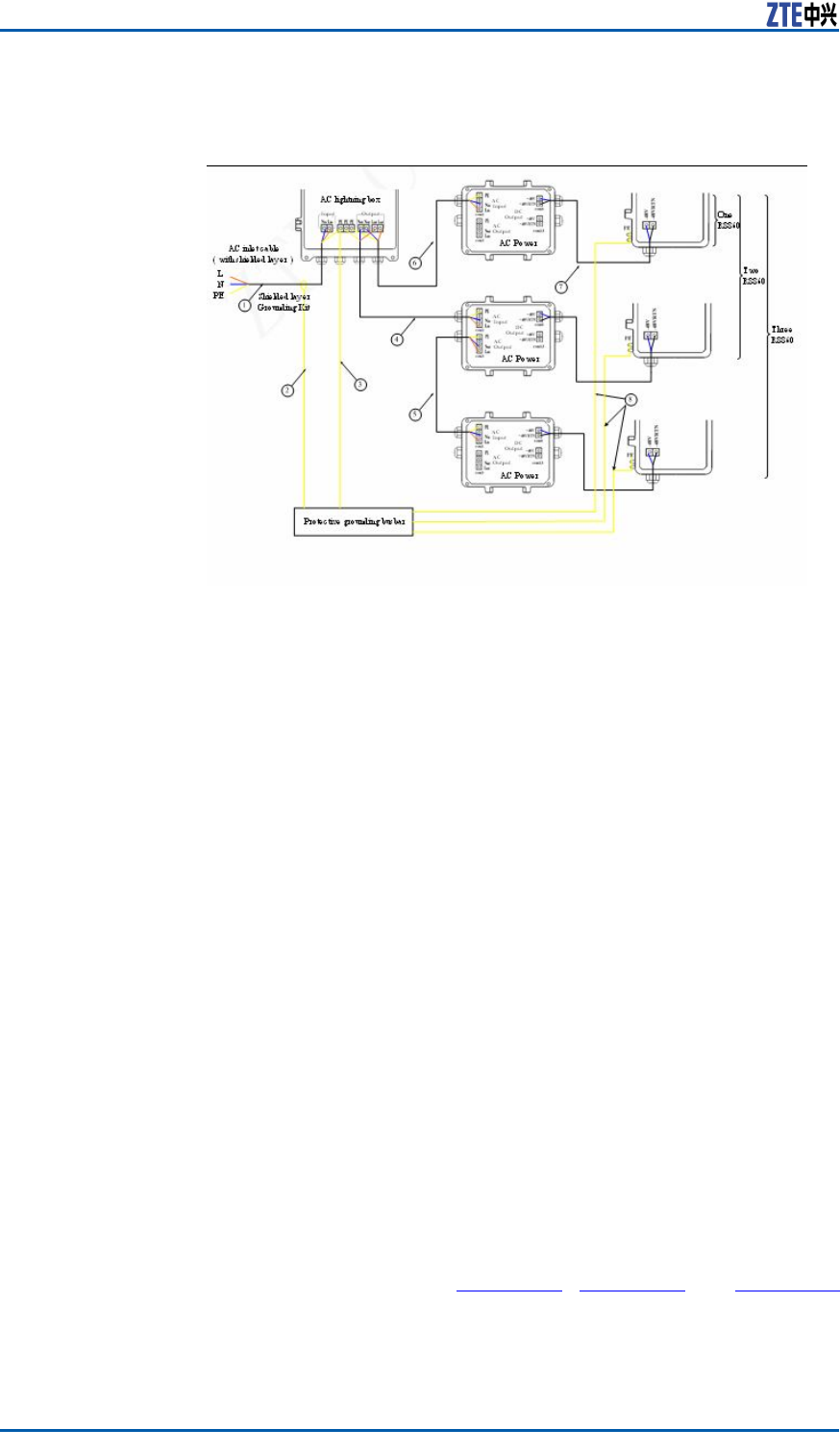
ZXSDRR8860InstallationManual
FIGURE135ONEACLIGHTNINGBOX,THREEOAUSANDTHREER8860
CABLECONNECTION
1.ACpowercable(Foroutdoorin-
stallation,three-coreoutdooralu-
minum-foilshieldingpowercable;
forindoorinstallation,PVCsheath
powercable;thecablelengthde-
pendsonsurveyonsite.)
2.Groundingcableofgroundingkit
(with1.5mlong)
3.Groundingcable(yellow-and-
greenre-retardantcable;the
lengthislessthan1m)
4.ACpowercable(three-coreout-
dooraluminum-foilshielding
powercable;thecablelengthde-
pendsonsurveyonsite.)
5.ACpowercable(three-coreout-
dooraluminum-foilshielding
powercable;thecablelengthde-
pendsonsurveyonsite.)
6.ACpowercable(three-coreout-
dooraluminum-foilshielding
powercable;thecablelengthde-
pendsonsurveyonsite.)
7.DCpowercable(four-core,with2
mlong)
8.Groundingcable(yellow-and-
greenre-retardantcable;the
lengthislessthan1m)
ShieldedGroundingKit
Installation
PrerequisiteTheshieldedpowercableisinstalled.
ContextThissectoronlydescribesinstallationofshieldedgroundingkitof
AClightningbox’spowercable.
Steps1.Selectaproperinstallationpositionforgroundingkit.Select
anappropriategroundingkitaccordingtodiameterofpower
cable.Cutoffsheathofpowercableandxtheshieldedlayer
ofpowercablewithagroundingkit.Thestructureofground-
ingkitisasshowninFigure136.Figure137andFigure138
illustratevariousgroundingkitsadoptedfordifferentdiame-
ters.
168ConfidentialandProprietaryInformationofZTECORPORATION
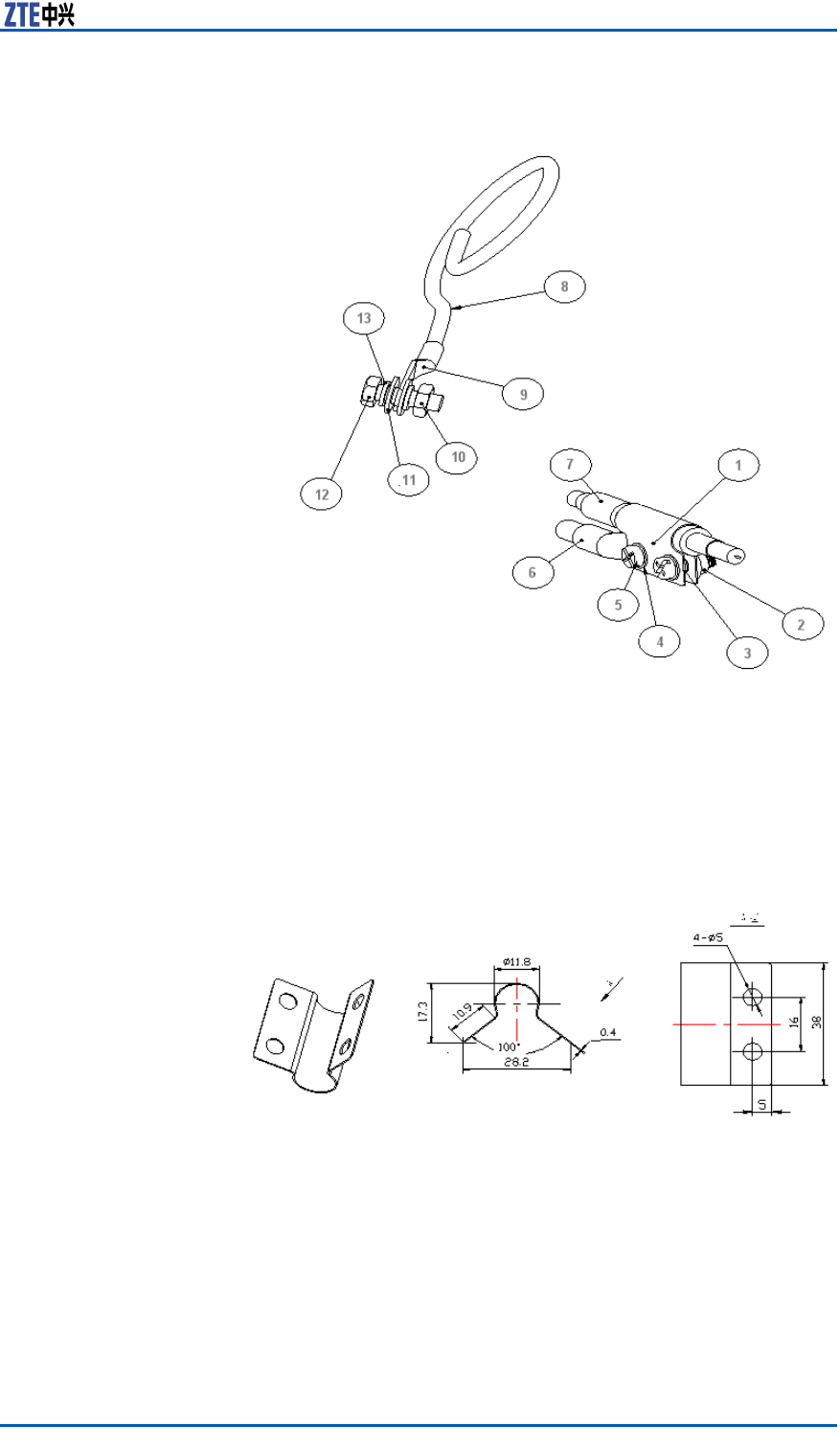
ChapterFACLightningArrester
FIGURE136SHIELDEDGROUNDINGKITSTRUCTURE
1.Groundingkitbody
2.Squeezescrew
3.O–typering4
4.Flatwasher4
5.ButtonheadedscrewM4×12
6.Connectingterminal(dual-
hole)
7.Shieldedpowercable
8.Groundingcable
9.Groundingterminal(single
hole)
10.Hexagonnut8
11.Flatwasher8
12.HexagonboltM8×25
13.Springwasher8
FIGURE137GROUNDINGBODY1(ADOPTABLEFOR6MM2TWO-CORE
OUTDOORPOWERCABLE)
ConfidentialandProprietaryInformationofZTECORPORATION169
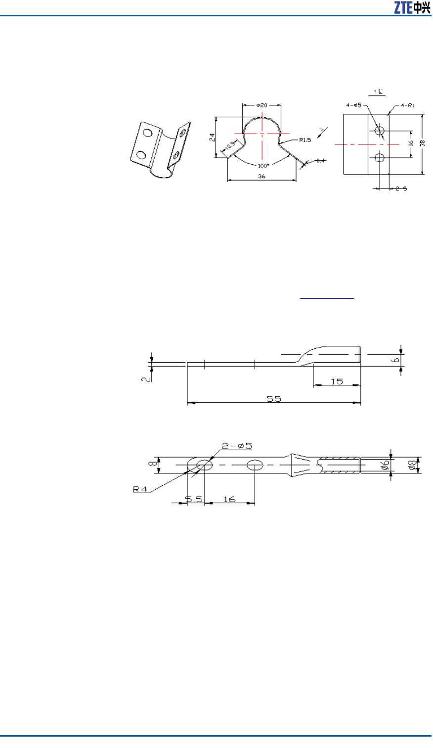
ZXSDRR8860InstallationManual
FIGURE138GROUNDINGBODY2(ADOPTABLEFOR16MM2TWO-CORE
OUTDOORPOWERCABLE)
2.Screwdownthedual-holeconnectingterminaltoxonthe
bodyofgroundingkit.Connecttheconnectingterminalwith
thegroundingcable.Protectthejunctionbetweengrounding
cableandconnectingterminalwiththermoplasticsleeve.Pull
thegroundingcabletowardsthegroundgrid.Thedual-hole
connectingterminalisasshowninFigure139.
FIGURE139CONNECTINGTERMINAL(DUAL-HOLE)
3.Performwaterproofprocessingforthejunctionbetween
groundingkitandpowercable.Themethodsaredescribedas
follows:
i.Wrapwaterproofself-adhesivetapeandthenwrapPVCad-
hesivetape.
ii.Whilewrappingwaterproofself-adhesivetape,rstwrap
layerbylayerfromdowntoup,thenfromuptodownand
nallyfromdowntoupagain.Theupperlayershouldcover
halfofthelowerlayer .
4.Fastenthesingle-holeconnectingterminalattheotherend
ofgroundingcabletothegroundingbarwithM8×25hexagon
bolts.Cleanawaypaintandoxidwithin13mmradiusofcon-
170ConfidentialandProprietaryInformationofZTECORPORATION
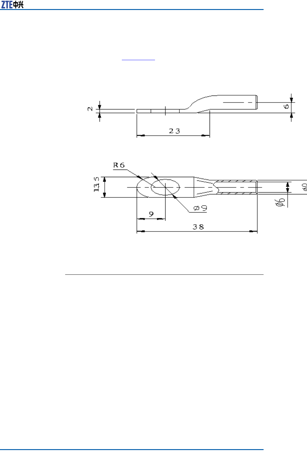
ChapterFACLightningArrester
nectingposition,andcoverantioxidationpasteonittomake
suregoodelectricalcontact.Afterconnectioncompleted,cover
alayerofantirustpaint.Thesingle-holeconnectingterminal
isasshowninFigure140.
FIGURE140CONNECTINGTERMINAL(SINGLE-HOLE)
ENDOFSTEPS.
ConfidentialandProprietaryInformationofZTECORPORATION171

ZXSDRR8860InstallationManual
Thispageisintentionallyblank.
172ConfidentialandProprietaryInformationofZTECORPORATION
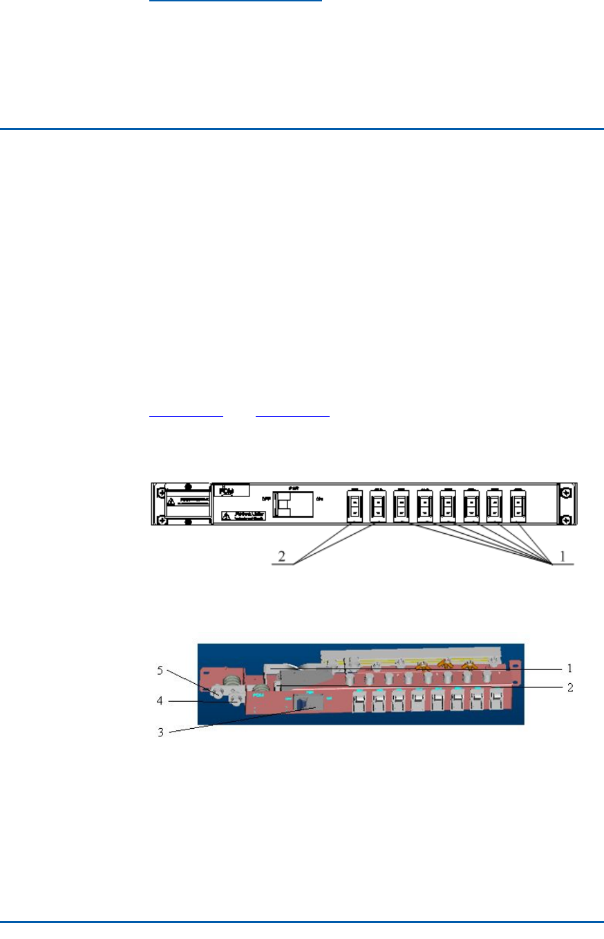
AppendixG
PDM
TableofContents:
PDMAppearanceandInterface.................................................173
PDMInstallation.....................................................................174
PDMAppearanceand
Interface
Powerdistributionmodule(PDM)isinstalledinasimpliedcabinet
totransferDCpowerforZXSDRR8860.Poweronoroffasingle
ZXSDRR8860bycontrolofswitchesonthePDM.
Figure141andFigure142illustratetheappearanceandinterfaces
ofPDM.
FIGURE141POWERDISTRIBUTIONBOXPLANE
1.BBUpowerswitch2.RRUpowerswitch
FIGURE142POWERDISTRIBUTIONBOX
1.–48VGNDoutputcopperbar
2.–48Voutputcopperbar
3.Powermainswitch
4.–48V
5.–48VGND
ConfidentialandProprietaryInformationofZTECORPORATION173
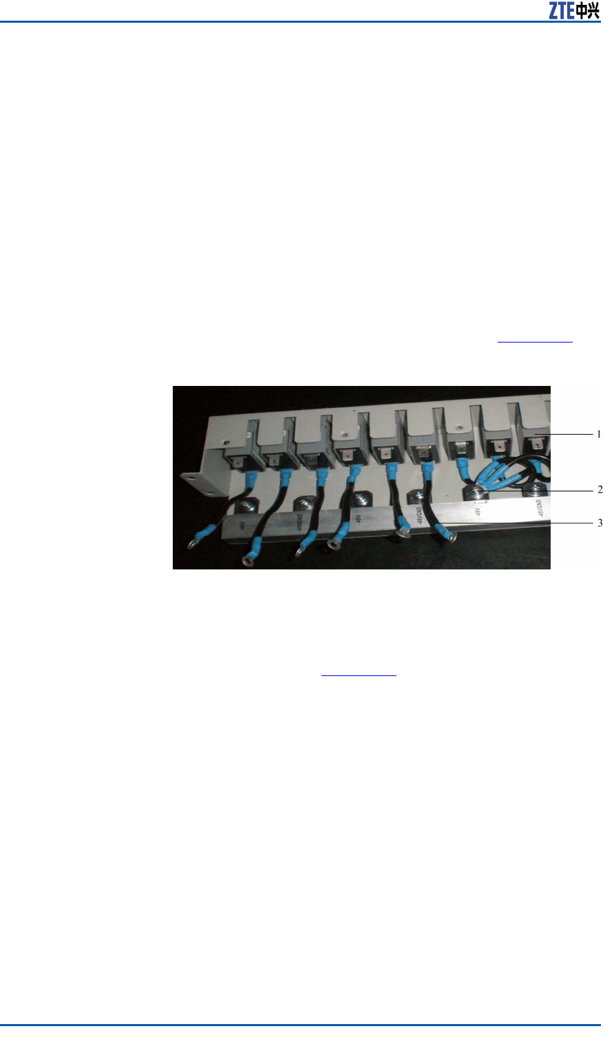
ZXSDRR8860InstallationManual
PDMInstallation
ContextThepowerdistributionmodule(PDM)isinstalledinanintegra-
tivecabinettotransferDCpowerforZXSDRB8200C100,ZXSDR
R8841C804orZXSDRR8860C806.
Steps1.Checkinstallationofpowerswitches.ThestatusofONandOFF
shouldbeconsistentwithsilkscreensonthePDMswitchplane.
2.Connectinternalcables.
ConnectanendofinternalcabletotheOFFendofpower
switchesandwrapadhesivetape,asshowninFigure143
FIGURE143INSIDECABLETOCONNECTWITHPDM
1.Powerswitch
2.Connectingterminal
3.Internalcable
3.InstallthePDMconnectedwithinternalcablestothesimplied
cabinet,asshowninFigure144.
174ConfidentialandProprietaryInformationofZTECORPORATION
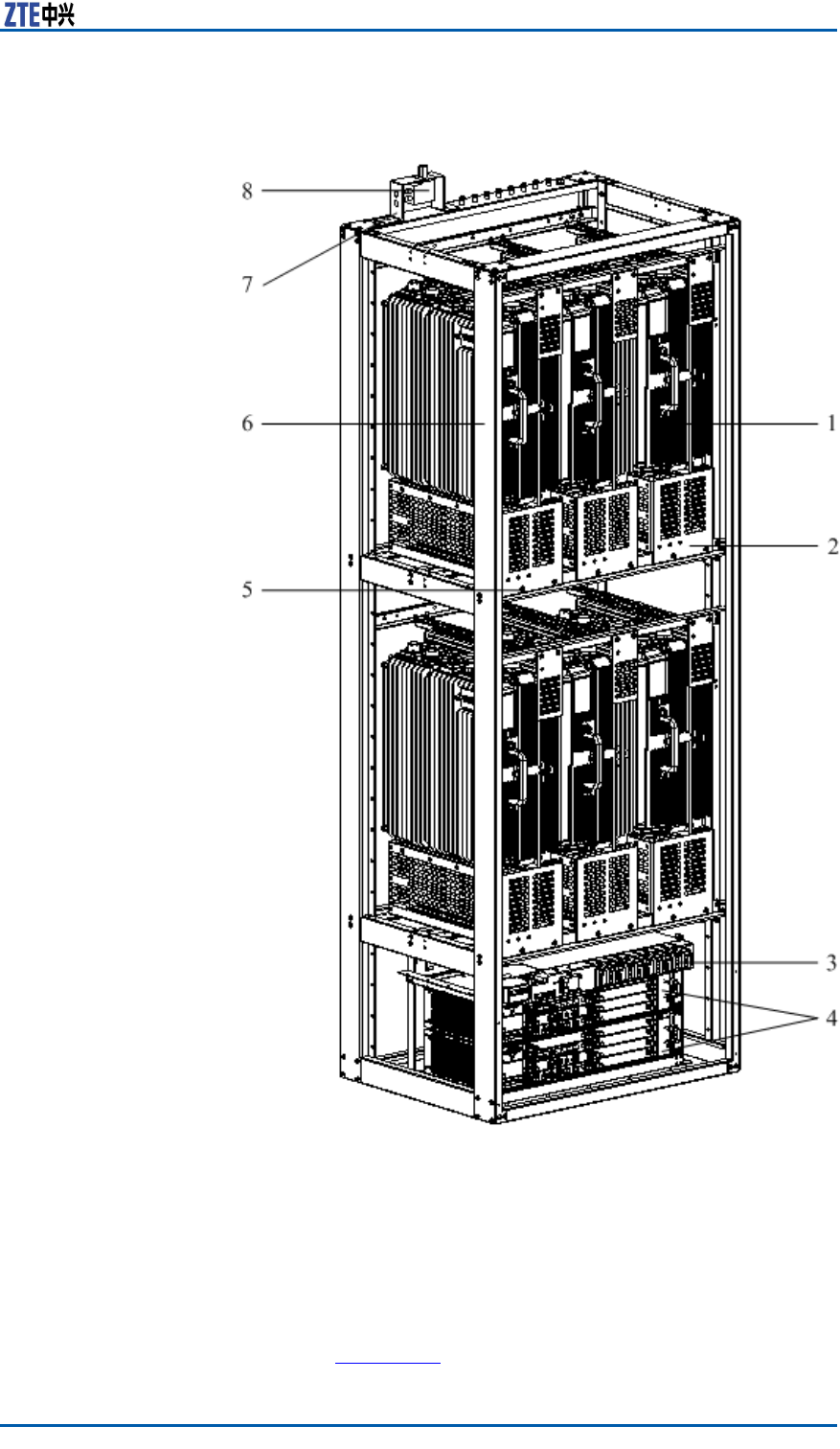
ChapterGPDM
FIGURE144PDMINSTALLATIONTOASIMPLIFIEDCABINET
1.ZXSDRR8860C806
2.ZXSDRR8860C806xation
shelf
3.PDM
4.ZXSDRB8200C100
5.PanscrewM6×16
6.Simpliedcabinet
7.GPSarresterrack
8.GPSarrester
4.InstallthepowercablesofBBUandRRU.Thepowercablecar-
riesfastenersbyitself,installedatabayonetofPDMback,as
showninFigure145.
ConfidentialandProprietaryInformationofZTECORPORATION175
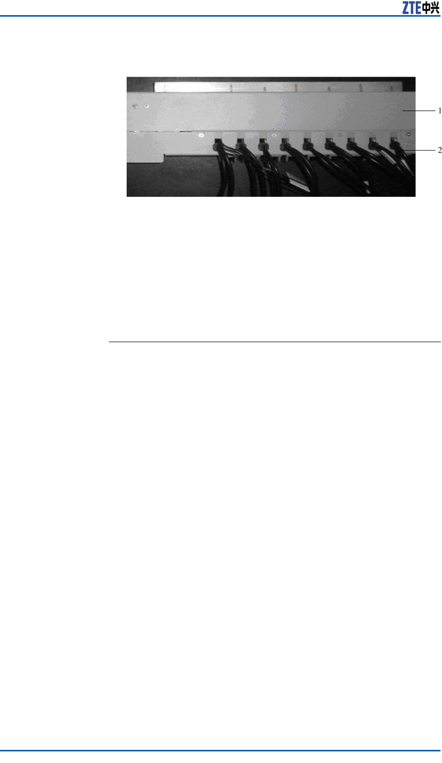
ZXSDRR8860InstallationManual
FIGURE145BBUANDRRUPOWERCABLEINSTALLATION
1.PDM2.Powercable
5.Connecttheotherendofinternalcablesto-48Vconnecting
terminal.Connectthe-48VendofBBUandRRUpowercables
totheONendofswitches.Connectthe-48VGNDendtothe
-48VGNDconnectingterminal.Thenscrewdownboltswitha
screwdriver .
6.ConnecttheinputpowercablecarriedbyPDMselftothecon-
nectingterminal.
ENDOFSTEPS.
176ConfidentialandProprietaryInformationofZTECORPORATION

Figures
Figure1InstallationFlow.....................................................8
Figure2PoleAnchorClampComponents..............................18
Figure3PoleFixingBracketComponents..............................19
Figure4Pole-mountInstallation(1).....................................20
Figure5Pole-mountInstallation(2).....................................21
Figure6Pole-mountInstallation(3).....................................21
Figure7Pole-mountInstallation(1).....................................22
Figure8Pole-mountInstallation(2).....................................23
Figure9Pole-mountInstallation(3).....................................24
Figure10WaveTrapInstallation..........................................24
Figure11Pole-mountInstallation(1)...................................25
Figure12Pole-mountInstallation(2)...................................26
Figure13Pole-mountInstallation(3)...................................26
Figure14Pole-mountInstallation(1)...................................27
Figure15Pole-mountInstallation(2)...................................28
Figure16Pole-mountInstallation(3)...................................29
Figure17Pole-mountInstallation(4)...................................30
Figure18WaveTrapInstallation..........................................31
Figure19InstallationCompletion........................................32
Figure20SupportingPanel.................................................33
Figure21HoleMarkingDesignT emplate(Unit:mm)..............34
Figure22SpaceRequirementforWall-mountInstallation
(Unit:mm).......................................................35
Figure23SupportingPanelInstallationonWall.....................36
Figure24MountingCabinet................................................37
Figure25GantryAppearance..............................................39
Figure26SupportingPanel.................................................40
Figure27FixUprightColumnandBasePlate.........................41
Figure28FastenUprightColumnandCoverPlate..................42
Figure29FastenTiltedSupport...........................................42
Figure30ZXSDRR8860IndoorGantry-mountInstallation
Appearance(onlyRRUinstalled)..........................44
Figure31FixUprightColumnandBasePlate.........................45
Figure32FastenUprightColumnandCoverPlate..................45
ConfidentialandProprietaryInformationofZTECORPORATION177

ZXSDRR8860InstallationManual
Figure33FastenTiltedSupport...........................................46
Figure34SupportingBracket..............................................47
Figure35SupportingBracketandWall-mountAssemblies.......48
Figure36ZXSDRR8860Installation.....................................49
Figure37WaveTrap..........................................................50
Figure38WaveTrapInstallation..........................................51
Figure39Gantry-mountIntegratedInstallation.....................52
Figure40Gantry-mountIntegratedInstallation(side)............53
Figure41SimpliedCabinetAppearance..............................55
Figure42UpperFixingFrame.............................................56
Figure43LowerFixingFrame.............................................57
Figure44HolePositionsandDimension................................58
Figure45ZXSDRR8860Assemblies.....................................59
Figure46ZXSDRR8860FixingBeam...................................60
Figure47LowerFixingFrameInstallation.............................61
Figure48ZXSDRR8860InstalledwithUpperandLower
FixingFrame.....................................................62
Figure49ZXSDRR8860InstallationtoSimpliedCabinet.......63
Figure50ZXSDRR8860InstallationCompletion....................64
Figure51SunShieldStructure............................................65
Figure52ExternalCableInstallationFlow.............................69
Figure53PowerCablestructure..........................................70
Figure54GroundingCableStructure....................................71
Figure55ZXSDRR8860GroundingBolt...............................71
Figure56Earth-networkCopperBar(Unit:mm)...................72
Figure57FiberConnectionbetweenZXSDRR8860andBBU...72
Figure58OpticalFiberInstallation.......................................73
Figure59FiberConnectionbetweenZXSDRR8860s...............74
Figure60OpticalFiberInstallation.......................................74
Figure61EnvironmentMonitoringCable...............................75
Figure62AviationJackAppearance.....................................75
Figure63AISGControlCableStructure................................76
Figure64FrequencyPointExtensionCable...........................77
Figure65RFJumperInstallation.........................................78
Figure66ZXSDRR8860ConguredwithCommonAntenna....80
Figure67ZXSDRR8860CongurationwithCommon
Antenna,AISGDualPowerAmplier....................81
Figure68ZXSDRR8860CongurationwithElectronic
AdjustmentAntenna(1).....................................82
178ConfidentialandProprietaryInformationofZTECORPORATION

Figures
Figure69ZXSDRR8860CongurationwithElectronic
AdjustmentAntenna(2).....................................83
Figure70ZXSDRR8860CongurationwithElectronic
AdjustmentAntenna.AISGDualPowerAmplier...84
Figure71MainAntennaFeederSystemInstallationFlow........87
Figure72AntennaInstallationPosition.................................88
Figure73DirectionalAntennaInstallation.............................89
Figure74AntennaDowntiltAdjustment................................90
Figure75OmniDirectionalAntennaInstallation.....................91
Figure76FeederFixing......................................................94
Figure77HoistingFeederT oTower......................................96
Figure78TripleFeederClipAppearance................................97
Figure79FeederGroundingSchematicDiagram....................98
Figure80GROUNDINGSYSTEM.........................................100
Figure81GroundingBarStructure.....................................101
Figure82GROUNDINGCLIP..............................................101
Figure83InstallationHolePositions(Unit:mm)..................103
Figure84HermeticWindowInstallation..............................104
Figure85FeederintoRoomMode(1).................................105
Figure86FeederintoRoomMode(2).................................106
Figure87Antenna,FeederandJumperInstallation..............108
Figure88WaterproofInsulationAdhesiveTape....................109
Figure89PVCAdhesiveT ape............................................110
Figure90WaterproofInsulationAdhesiveTapeWrap............110
Figure91ConnectorafterProcessing.................................111
Figure92FeederHermetic-windowDimension(Unit:mm)....112
Figure9312FeederHermetic-windowStructure..................112
Figure94InstallationHolePositions(Unit:mm)..................113
Figure95FeederHermetic-windowInstallation....................114
Figure96CabinetJumpers...............................................115
Figure97ZXSDRR8860Cabinet-combinedInstallation
Connection.....................................................126
Figure98CascadedCabinetConnection..............................129
Figure99ZXSDRR8860OpticalFiberforCascadedCabinet..130
Figure100OAUAppearance..............................................133
Figure101OAUInterfaces................................................133
Figure102AnchorClampAssemblies.................................134
Figure103FixingBracketAssemblies.................................134
Figure104TwoSetsofAnchorClampAssemblies................135
Figure105TwoSetsofFixingBracketAssemblies................136
ConfidentialandProprietaryInformationofZTECORPORATION179

ZXSDRR8860InstallationManual
Figure106OAUBracket...................................................137
Figure107TwoSetsofSupportingPanels...........................137
Figure108ThreeSetsofSupportingPanels........................138
Figure109OAUInstallation(1).........................................139
Figure110OAUInstallation(2).........................................140
Figure111OAURack.......................................................141
Figure112OAUInstallation(1).........................................142
Figure113OAUInstallation(2).........................................143
Figure114WaterproofEndCap.........................................144
Figure115LooseoffWaterproofEndCap............................144
Figure116WaterproofEndCapStructure...........................145
Figure117WaterproofEndCapInstallation.........................145
Figure118ACPowerCableConnection...............................146
Figure119OneACLightningBox,ThreeOAUsandThree
R8860CableConnection...................................147
Figure120OutdoorDCLightningBoxAppearance................150
Figure121OutdoorDCLightningBoxInterface...................151
Figure122InstallationParts.............................................152
Figure123OutdoorDCLightningPoleInstallation................153
Figure124OutdoorDCLightningBoxInterfaces..................154
Figure125OutdoorDCLightningConnection......................155
Figure126IndoorDCLightningBoxAppearance..................158
Figure127IndoorDCLightningBoxInterfaces....................159
Figure128IndoorDCLightningBoxCableConnection(not
connectwithremotealarm)..............................160
Figure129ACLightningBoxAppearance............................162
Figure130ACLightningBoxInterface................................163
Figure131ACLightningBoxInstallationParts.....................164
Figure132ACLightningPoleInstallation............................165
Figure133OneACLightningBoxandOne(ortwo)R8841
CableConnection.............................................166
Figure134TwoACLightningBoxandThreeR8841Cable
Connection.....................................................167
Figure135OneACLightningBox,ThreeOAUsandThree
R8860CableConnection...................................168
Figure136ShieldedGroundingKitStructure.......................169
Figure137GroundingBody1(adoptablefor6mm2two-core
outdoorpowercable).......................................169
Figure138GroundingBody2(adoptablefor16mm2two-core
outdoorpowercable).......................................170
180ConfidentialandProprietaryInformationofZTECORPORATION

Figures
Figure139ConnectingT erminal(dual-hole)........................170
Figure140ConnectingT erminal(single-hole)......................171
Figure141PowerDistributionBoxPlane.............................173
Figure142PowerDistributionBox.....................................173
Figure143InsideCabletoconnectwithPDM......................174
Figure144PDMInstallationtoaSimpliedCabinet..............175
Figure145BBUandRRUPowerCableInstallation................176
ConfidentialandProprietaryInformationofZTECORPORATION181

ZXSDRR8860InstallationManual
Thispageisintentionallyblank.
182ConfidentialandProprietaryInformationofZTECORPORATION

Tables
Table1SafetySymbolsDescription.......................................2
Table2ToolandMeterList...................................................9
Table3ZXSDRR8860EngineeringIndices............................15
Table4JD40K085C20H2–K1ZDCLightningBoxTechnical
Indices.............................................................16
Table5GPAD501M54-1AExternalAC-to-DCConversion
LightningBoxTechnicalIndices...........................16
Table6MainComponentList1............................................17
Table7MainComponentList2............................................17
Table8MainComponentList3............................................18
Table9MainComponents...................................................33
Table10MainComponents.................................................38
Table11MainComponents.................................................40
Table12ZXSDRR8860ExternalCableConnection
Relationship......................................................67
Table13ColorandSpecication..........................................70
Table14CablePinDescription.............................................76
Table15AISGControlCableDescription...............................77
Table16ConnectionRelationship.......................................118
Table17ConnectionRelationship.......................................119
Table18EngineeringTechnicalIndices...............................131
Table19OAUInputCharacters..........................................131
Table20OAUOutputCharacters........................................132
Table21EngineeringTechnicalIndices...............................149
Table22EngineeringTechnicalIndices...............................157
Table23EngineeringTechnicalIndices...............................161
ConfidentialandProprietaryInformationofZTECORPORATION183

ZXSDRR8860InstallationManual
Thispageisintentionallyblank.
184ConfidentialandProprietaryInformationofZTECORPORATION

ListofGlossary
AISG-AntennaInterfaceStandardsGroup
BBU-BaseBandUnit
VSWR-VoltageStandingWaveRatio
ConfidentialandProprietaryInformationofZTECORPORATION185