ZTE ZXV10H100 Home Gateway User Manual H100 en
ZTE Corporation Home Gateway H100 en
UserManual.wiki
>
ZTE
>
ZXV10H100 User Manual
Users Manual
Navigation menu
Upload a User Manual
Namespaces
Wiki Guide
HTML
PDF
Info
Views
User Manual
Discussion / Help
Navigation
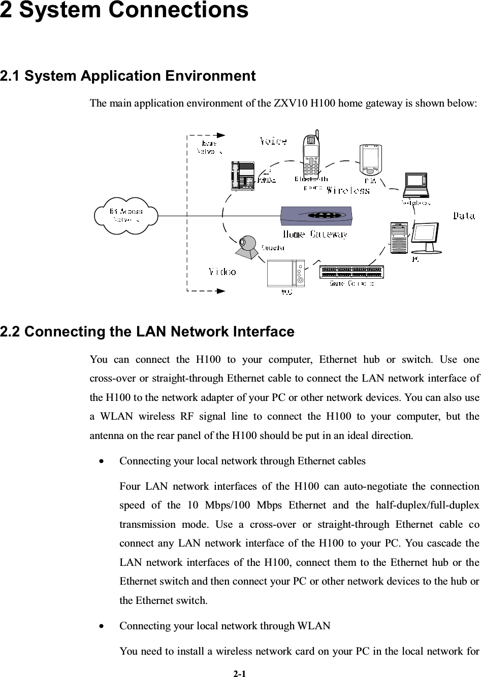
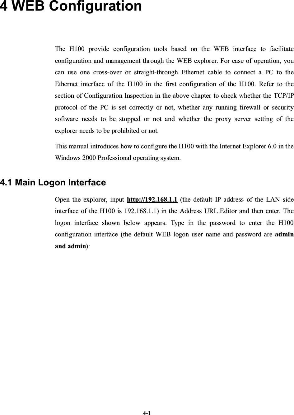
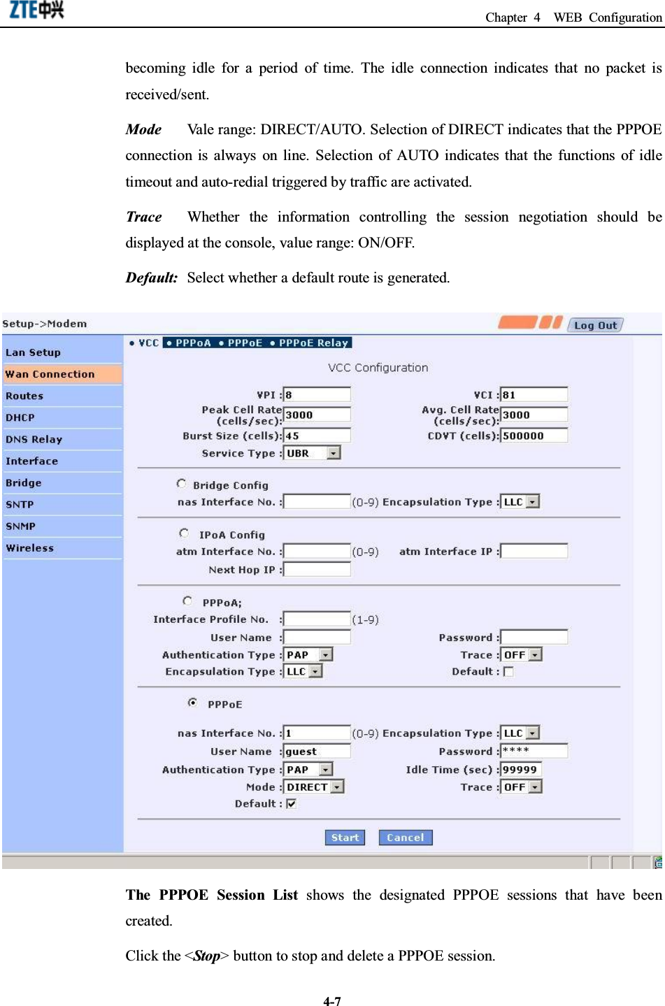
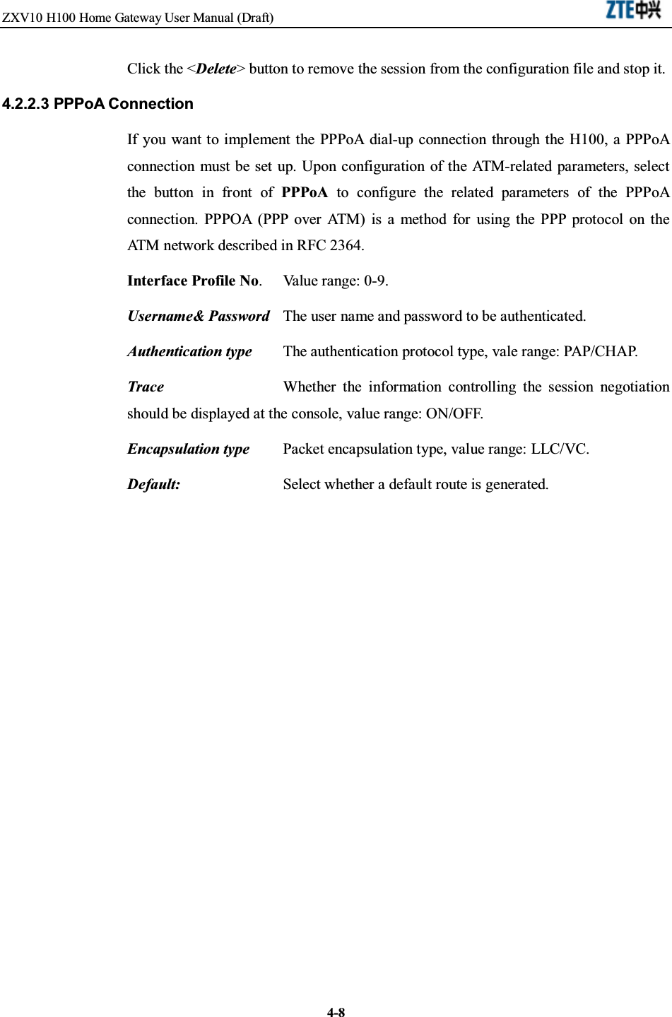
![PrefaceManual DescriptionThank you for choosing the wireless Local Area Network (LAN) product-ZXV10H100 of ZTE Corporation.The ZXV10 H100 home gateway is a modular access gateway in the center of a homenetwork. It links multiple devices through Internet connections and provides users withsafe communication, entertainment and storage functions.How to Use This ManualThis manual describes in detail the installation and configuration methods of thisproduct. Before installation or use of this product, please read this manual carefully tocomprehensively understand the functions of this product.ConventionsThis manual contains the following conventions in symbols, keyboard operations,mouse operations and warning marks.1. SymbolsThe information with an angular bracket stands for a key name, button name orthe information that is input at the terminal by an operator. The information witha square bracket stands for the man-machine interface, menu bar, data table, andfield name. A multi-level menu is separated with an arrow. For example, themulti-level menu [File→New→Folder] stands for the menu item [Folder] underthe submenu [New] under the menu [File].2. Keyboard operation conventionFormat MeaningCharacters in angle bracketsKey or button name. For example, <Enter>, <Tab>,<Backspace> and <a> mean carriage return, tab key, backspacekey and letter "a” in lower case.<key 1+ key 2>Press several keys on the keyboard at the same time. Forexample, <Ctrl + Alt + A> means pressing “Ctrl”, “Alt”, and “A”at the same time.](https://usermanual.wiki/ZTE/ZXV10H100/User-Guide-685325-Page-5.png)
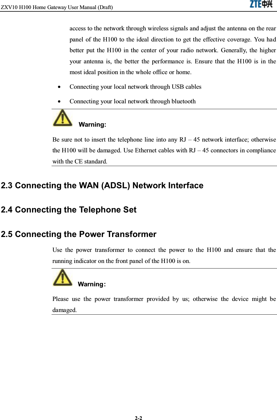
![3-13 Client Settings3.1 TCP/IP InstallationIf your client PC is not installed with the TCP/IP protocol, please refer to the followingsettings:Click the <Start> button, select [Settings] and then click the [Network and Dial-upConnections] icon;Double click the [Local Connections] icon and then click the <Properties> button inthe [Local Connections] tab;Click the <Install…> button and then double click the [Protocols] icon;Select [Internet Protocol (TCP/IP)] and then click the <OK> button to finish theprotocol installation.](https://usermanual.wiki/ZTE/ZXV10H100/User-Guide-685325-Page-19.png)
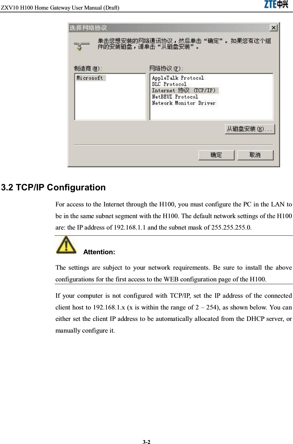
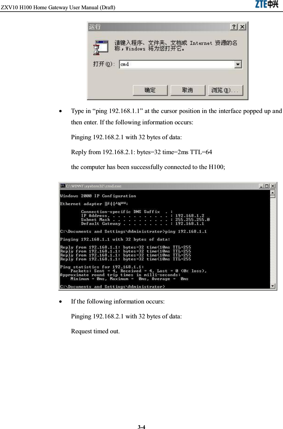
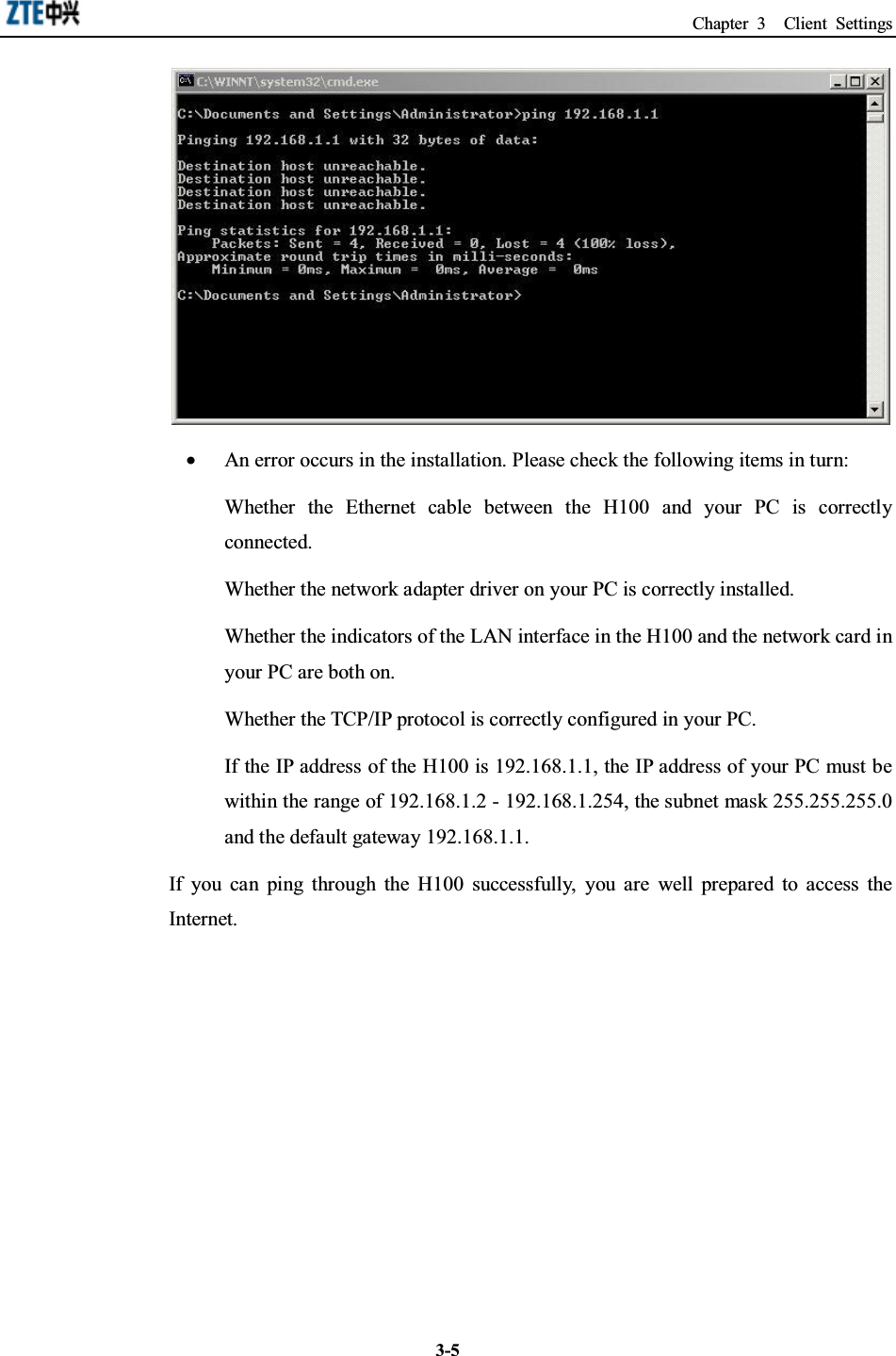
![Chapter 3 Client Settings3-33.3 Configuration InspectionAfter the above preparations, switch on the H100, and you will see that the powerindicator is on. At the same time, the H100 executes the device start-up process anddetects the connected devices. You can see from the indicators which devices havebeen connected to the H100 successfully. The indicators of the network interfacesconnecting to successfully connected devices will be solid on.You may also use the PING command to check the network connection status of the PCand the H100. For example, the steps for connection through the Ethernet interface in[Local Connections] in the Windows 2000 operating system are as follows:•Click the [Start→Run] menu;•Type in “CMD” in the dialog box popped up and then enter;](https://usermanual.wiki/ZTE/ZXV10H100/User-Guide-685325-Page-21.png)
![ZXV10 H100 Home Gateway User Manual (Draft)4-24.2 Basic ConfigurationClick the <Setup> button in the WEB interface to enter the basic configuration of theH100. In the basic configuration, you can configure the parameters such as LANinterface parameter, ADSL WAN connection parameter, static route and RIPdynamic route protocol, DHCP Server and DHCP Relay, DNS Relay, Bridgeconnection, STP (Spanning Tree Protocol), SNTP (Simple Network Time Protocol),SNMP (Simple Network Management Protocol) and WLAN (IEEE802.11b/g)parameter.4.2.1 LAN Interface InformationClick the LAN Setup link in the left of the interface to enter the [LAN Setup]interface, where you can configure the IP address of the Ethernet interface of the H100.LAN IP address: IP address of Ethernet interface eth0LAN netmask: Subnet mask of Ethernet interface eth0](https://usermanual.wiki/ZTE/ZXV10H100/User-Guide-685325-Page-26.png)
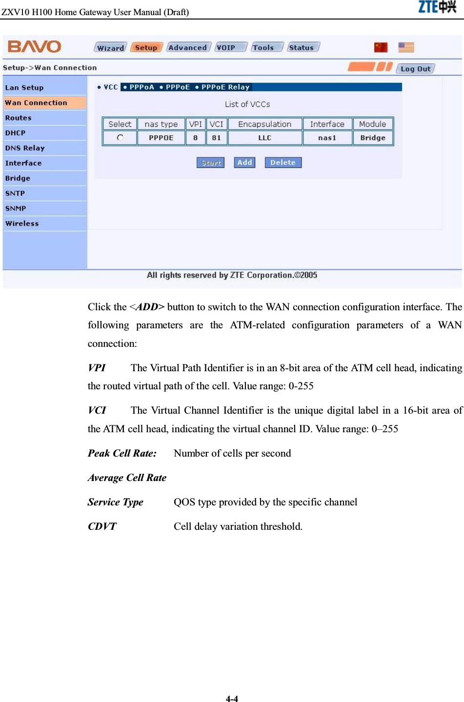
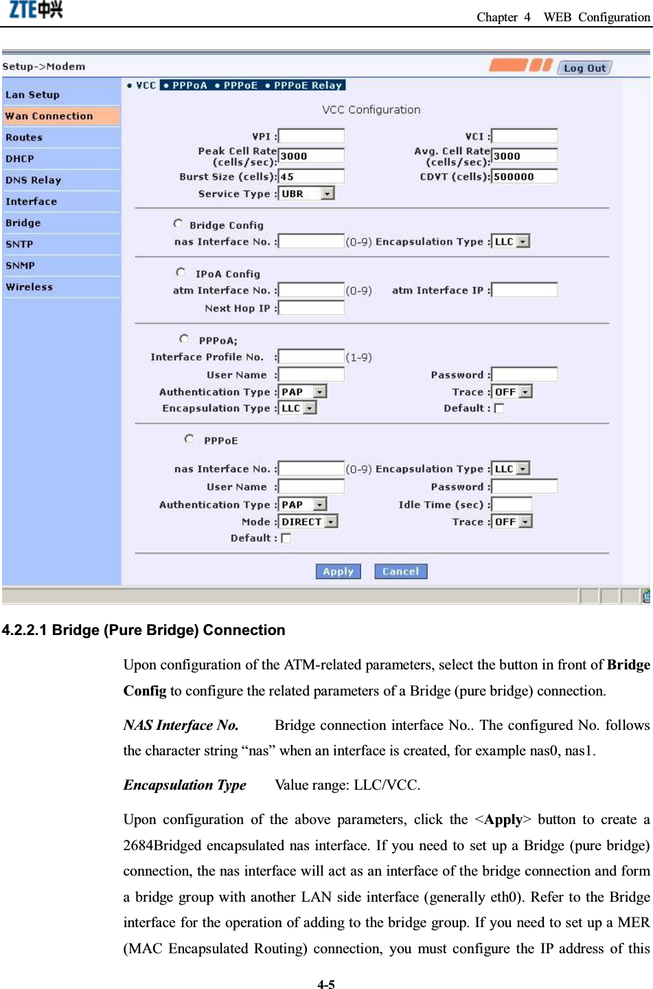
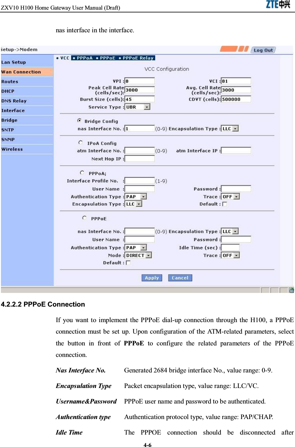
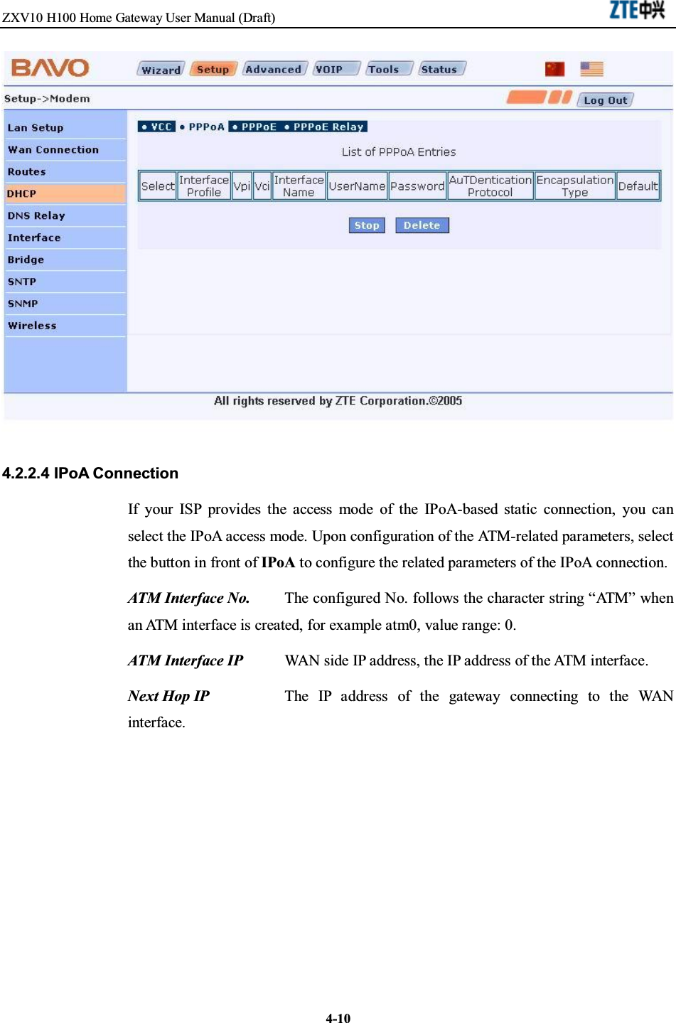
![Chapter 4 WEB Configuration4-34.2.2 ADSL WAN ConnectionClick the WAN Connection link in the left of the interface to enter the [WA NConnection] interface, where you can set ADSL-based access modes, such as Bridge,PPPoE, PPPoA and IPoA.Attention:For the PPPoE, PPPoA and IPoA connection modes, the Network Address Translation(NAT) function is activated in the H100 by default.The first [WAN Connection] interface shows the list of configured VCCs (VirtualChannel Connection) in the H100. You may use the <Start/Stop>, <Add> and <Delete>buttons to start/stop, add or delete an ADSL link.](https://usermanual.wiki/ZTE/ZXV10H100/User-Guide-685325-Page-27.png)
![Chapter 4 WEB Configuration4-114.2.3 Static RouteClick the Routes link in the left of the interface to enter the route configurationinterface of the H100. In the [Route] tab, you can configure and view the static routeinformation of the H100. The main interface shows the static route list of the H100.You can configure a new route, modify or delete the existing routes. The [RIP] tab inthe interface is used to configure the dynamic route protocol RIP of the H100.If you need to add a new route, designate the destination network ID, subnet mask,next hop IP and click the <Add> button. Once a route is added, the route list will berefreshed. To add a host-based route, input the destination network ID and the next hopIP address. In this case, the [Destination Subnet Mask] option is invalid.If you need to add a network-based route, please check the [Network Based Route]checkbox to enable the [Destination Subnet Mask] box and input a proper value.](https://usermanual.wiki/ZTE/ZXV10H100/User-Guide-685325-Page-35.png)
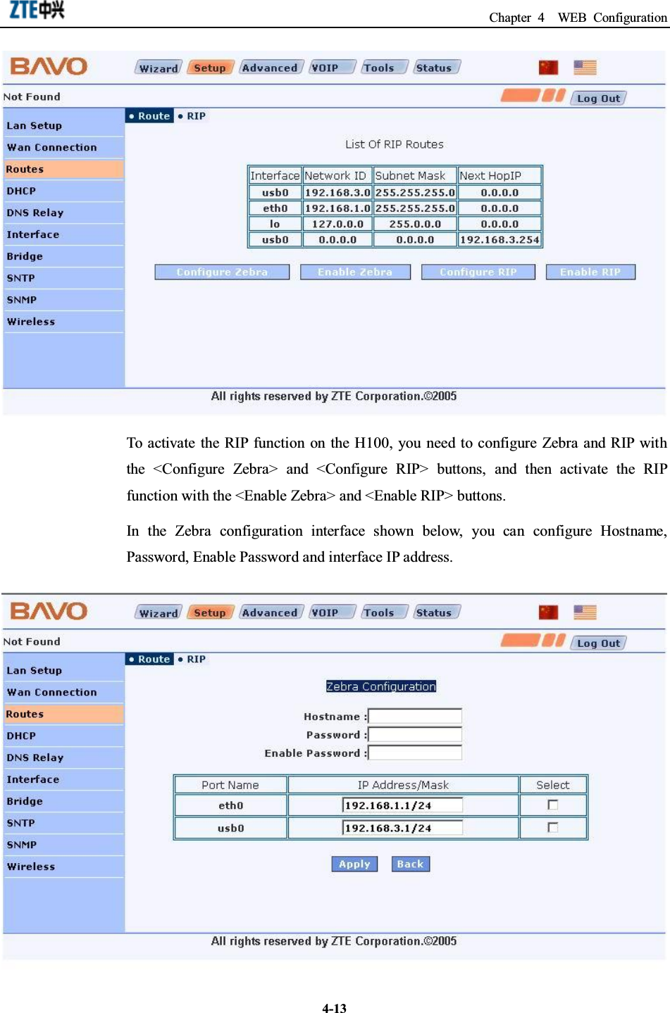
![ZXV10 H100 Home Gateway User Manual (Draft)4-12If you need to modify an existing route, select it in the route list. Its configuration isshown in the set box. Modify the next hop IP address and click the <Modify> button.If you need to delete an existing route, select it and click the <Delete> button. Afterthat, the route list is refreshed.4.2.4 RIP Dynamic RouteClick the [RIP] tab in the main route configuration interface to enter the configurationinterface of the dynamic route protocol RIP, as shown below. The main RIPconfiguration interface shows the route table information of the system.](https://usermanual.wiki/ZTE/ZXV10H100/User-Guide-685325-Page-36.png)

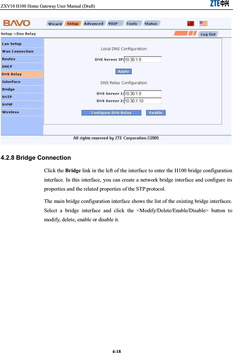
![Chapter 4 WEB Configuration4-174.2.7 DNS RelayDNS Relay Configuration Interface:DNS Server IP The DNS server IP address at the LAN side set in [Local DNSConfiguration] option. Upon configuration, you should click the <Apply> button.DNS Server 1 and DNS Server 2 When the DNS relay function is configured, the IPaddresses of the DNS servers should be filled in the [DNS Server 1] and [DNS Server2] boxes. Click the <Configure DNS Relay> button to complete the setting.DNS Relay To enable the DNS relay function, click the <Enable> button. Uponenabling of the DNS relay function, the content displayed on the button changes toDisable.](https://usermanual.wiki/ZTE/ZXV10H100/User-Guide-685325-Page-41.png)
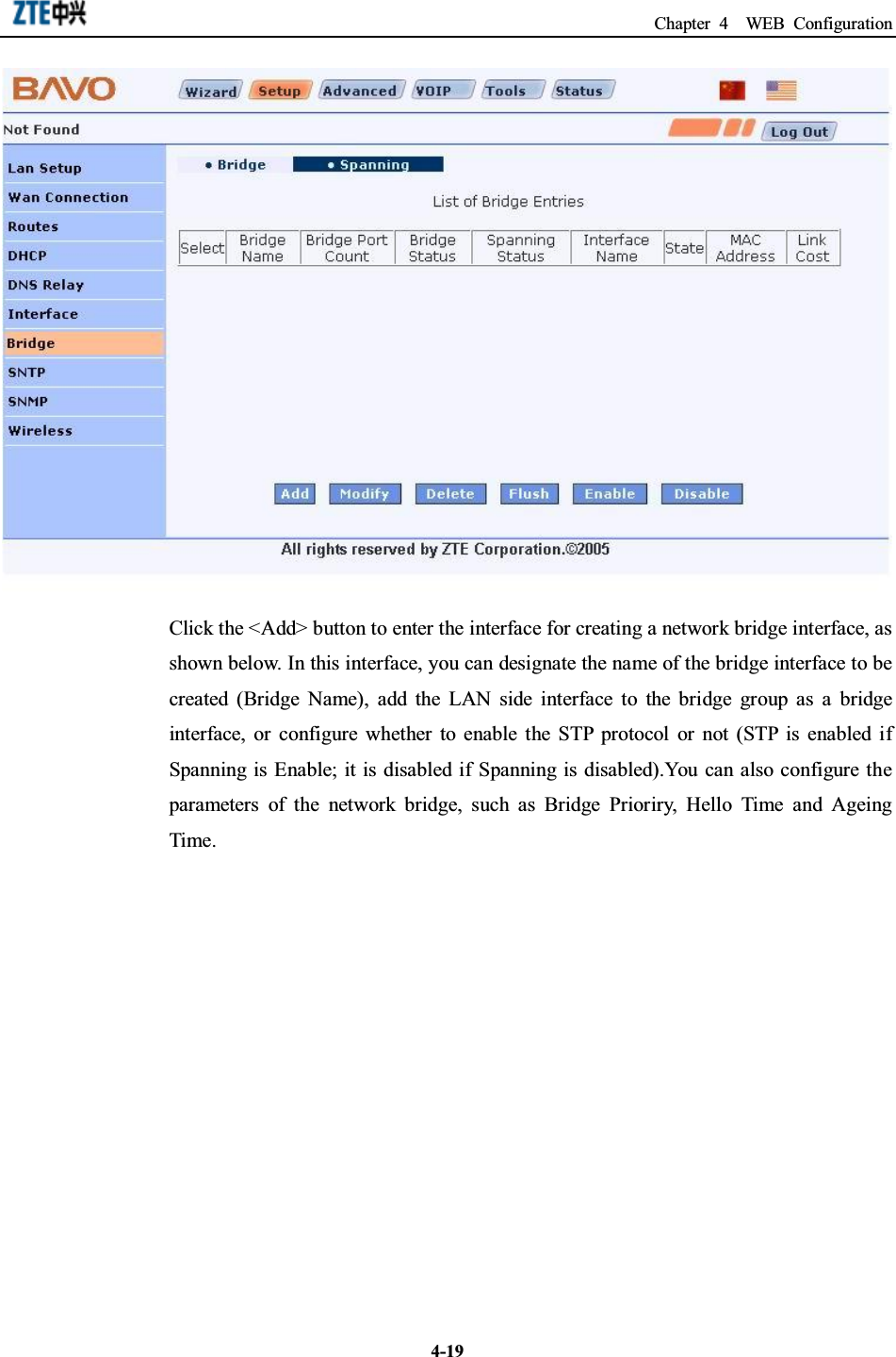
![ZXV10 H100 Home Gateway User Manual (Draft)4-20Click the [Spanning] tab in the bridge configuration interface to enter the STPparameter configuration interface, as shown below. In this interface, you can configurethe Link Cost property of the member ports in the network bridge.](https://usermanual.wiki/ZTE/ZXV10H100/User-Guide-685325-Page-44.png)