Users Manual

Confidential
ZXV10 H100 Home Gateway
User Manual (Draft)
ZTE CORPORATION

ZXV10H100HomeGateway
User Manual (Draft)
Manual Version
Product Version V1.0
Copyright © 2004 ZTE Corporation
All rights reserved.
No part of this documentation may be excerpted, reproduced, translated, annotated or
duplicated, in any form or by any means without the prior written permission of ZTE
Corporation.
ZTE CORPORATION
ZTE Plaza, Keji Road South, Hi-Tech Industrial Park, Nanshan District, Shenzhen, P.R.China
Website: http://www.zte.com.cn
Postcode: 518057
Customer Support Center: (+86755) 26771900 800-9830-9830
Fax: (+86755) 26770801
Email: support@zte.com.cn
****
S.N.:

FAX: +86-755-26770160
Suggestions and Feedback
To improve the quality of ZTE product documentation and offer better services to our customers, we hope
you can give us your suggestions and comments on our documentation and fax this form to
+86-755-26770160; or mail to “Marketing center 3rd floor ZTE Plaza, Keji Road South, Hi-Tech Industrial
Park, Nanshan District, Shenzhen, P. R. China”. Our postcode is 518057.
Document name ZXV10 H100 Home Gateway User Manual (Draft)
Product version V1.0 Document version
Equipment installation time
Your information
Name Company
Postcode Company address
Telephone E-mail
Presentation: How is information presented? (Introductions, procedures, illustrations, others)
Good Fair Average Poor Bad
Accessibility: Can you find the information you want? (Table of contents, Index, headings,
numbering, others)
Good Fair Average Poor Bad
Your evaluation
of this
documentation
Intelligibility: Can you understand it when you find it? (Language, vocabulary, readability, others)
Good Fair Average Poor Bad
Presentation:
Accessibility:
Your suggestions
for improvement
of this
documentation
Intelligibility:
Your other
suggestions on
ZTE product
documentation

Preface
Manual Description
Thank you for choosing the wireless Local Area Network (LAN) product-ZXV10
H100 of ZTE Corporation.
The ZXV10 H100 home gateway is a modular access gateway in the center of a home
network. It links multiple devices through Internet connections and provides users with
safe communication, entertainment and storage functions.
How to Use This Manual
This manual describes in detail the installation and configuration methods of this
product. Before installation or use of this product, please read this manual carefully to
comprehensively understand the functions of this product.
Conventions
This manual contains the following conventions in symbols, keyboard operations,
mouse operations and warning marks.
1. Symbols
The information with an angular bracket stands for a key name, button name or
the information that is input at the terminal by an operator. The information with
a square bracket stands for the man-machine interface, menu bar, data table, and
field name. A multi-level menu is separated with an arrow. For example, the
multi-level menu [File→New→Folder] stands for the menu item [Folder] under
the submenu [New] under the menu [File].
2. Keyboard operation convention
Format Meaning
Characters in angle brackets
Key or button name. For example, <Enter>, <Tab>,
<Backspace> and <a> mean carriage return, tab key, backspace
key and letter "a” in lower case.
<key 1+ key 2>
Press several keys on the keyboard at the same time. For
example, <Ctrl + Alt + A> means pressing “Ctrl”, “Alt”, and “A”
at the same time.

Format Meaning
<key, key 2>
Press the first key, and then release it and then press the second
key.For example, <Alt, F> means pressing the “Alt” key, and
then releasing it and then pressing the “F” key.
3. Mouse operation convention
Format Meaning
Click Press and release the left mouse button promptly
Double-click Quickly press twice the left button of the mouse and then release
it.
Right-click Quickly press and release the right button of the mouse
Drag Press and hold the left button of the mouse and move the mouse
4. Identifier
Four eye-catching symbols will appear in this manual to indicate the places
worthy of special attentions during operation:
Attention , Caution ,Warning ,and Danger:
alerting you to some important instructions.
Statement: The actual product may differ from what is described in this
manual due to frequent update of ZTE products and fast development of
technologies. Please contact the local ZTE office for the latest updating
information of the product.
CAUTION: changes or modifications made in the radio phone,
not expressly approved by ZTE, will void the user's authority to
operate the equipment.
-i-
Contents
1 Introduction of the Product ................................................................................................................... 1-1
1.1 Introduction of the Product ............................................................................................................ 1-1
1.2 Packing List of the Product............................................................................................................ 1-1
1.3 Features of the Product .................................................................................................................. 1-1
1.4 Appearance of the Product ............................................................................................................. 1-2
1.5 System Requirements..................................................................................................................... 1-4
2 System Connections ................................................................................................................................ 2-1
2.1 System Application Environment .................................................................................................. 2-1
2.2 Connecting the LAN Network Interface........................................................................................ 2-1
2.3 Connecting the WAN (ADSL) Network Interface ......................................................................... 2-2
2.4 Connecting the Telephone Set........................................................................................................ 2-2
2.5 Connecting the Power Transformer ............................................................................................... 2-2
3 Client Settings ......................................................................................................................................... 3-1
3.1 TCP/IP Installation......................................................................................................................... 3-1
3.2 TCP/IP Configuration .................................................................................................................... 3-2
3.3 Configuration Inspection ............................................................................................................... 3-3
4 WEB Configuration................................................................................................................................ 4-3
4.1 Main Logon Interface .................................................................................................................... 4-3
4.2 Basic Configuration ....................................................................................................................... 4-3
4.2.1 LAN Interface Information ................................................................................................. 4-3
4.2.2 ADSL WAN Connection ..................................................................................................... 4-3
4.2.3 Static Route......................................................................................................................... 4-3
4.2.4 RIP Dynamic Route ............................................................................................................4-3
-ii-
4.2.5 DHCP Server ...................................................................................................................... 4-3
4.2.6 DHCP Relay ....................................................................................................................... 4-3
4.2.7 DNS Relay.......................................................................................................................... 4-3
4.2.8 Bridge Connection.............................................................................................................. 4-3
4.2.9 SNTP .................................................................................................................................. 4-3
4.2.10 SNMP ............................................................................................................................... 4-3
4.2.11 WLAN .............................................................................................................................. 4-3
4.3 Advanced Configuration................................................................................................................ 4-3
4.3.1 ADSL Mode Configuration ................................................................................................ 4-3
4.3.2 Firewall Configuration ....................................................................................................... 4-3
4.3.3 MAC Filter ......................................................................................................................... 4-3
4.3.4 IPQoS ................................................................................................................................. 4-3
4.3.5 UPnP................................................................................................................................... 4-3
4.3.6 VLAN ................................................................................................................................. 4-3
4.3.7 Bluetooth ............................................................................................................................ 4-3
4.4 VOIP Configuration....................................................................................................................... 4-3
4.4.1 Protocol Selection/Switchover............................................................................................ 4-3
4.4.2 SIP Configuration ............................................................................................................... 4-3
4.4.3 MGCP Configuration..........................................................................................................4-3
4.4.4 Voice Configuration............................................................................................................ 4-3
4.5 Other Operation Tools ................................................................................................................... 4-3
4.5.1 Configuring the Save and Restore ...................................................................................... 4-3
4.5.2 Device Reset Operation ...................................................................................................... 4-3
4.5.3 Network Connectivity Test Tool: PING.............................................................................. 4-3
4.5.4 ATM OAM Loopback......................................................................................................... 4-3
4.6 Equipment Status and Statistics..................................................................................................... 4-3

-iii-
Appendix A Radio Client Configuration................................................................................................. A-3
Appendix B FAQ....................................................................................................................................... B-3
Appendix C Technical Specification........................................................................................................ C-3
1-1
1 Introduction of the Product
1.1 Introduction of the Product
Thank you for choosing the wireless Local Area Network (LAN) product-ZXV10
H100 of ZTE Corporation.
The ZXV10 H100 home gateway is a modular access gateway in the center of a home
network. It links multiple devices through Internet connections and provides users with
safe communication, entertainment and storage functions.
1.2 Packing List of the Product
The package of the H100 product should contain the following components:
•One H100 host
•One DC power transformer
•One RJ45 10/100BaseT Ethernet cross-connect connection line and one
•parallel connection line
•Two RJ11 telephone lines
•USB Slave connection line
•One Manual and Toolkit CD
•One user manual
•Guarantee card
•Certificate of quality
If any of the above components is missing or damaged, please contact your dealer. In
case of replacement, please keep the package and existing components of the product
well.
1.3 Features of the Product
•Interface Features

ZXV10 H100 Home Gateway User Manual (Draft)
1-2
WAN si de:
ADSL interface: Built-in splitter, compatible with ADSL/ADSL2/2+
LAN side:
Fast Ethernet port: four, RJ-45, 10/100Mbps, complies with the IEEE802.3
and IEEEE802.3u standards
WLAN interface: Complies with the IEEE 802.11g/b standard, built-in antenna
Blue Tooth interface: Supports Core V1.2, built-in antenna
POTS interface: RJ11, 2-port
USB interface: 1 master (V2.0) & 1 slave (V1.1)
Extended interface (optional):
Card Bus: One, supports the 16-bit PCMCIA and 32-bit CARDBUS cards
•Technical Features
It implements two functions: data access and IP voice. The data exchange and
forwarding functions of Layer 2 and Layer 3 are implemented for data access
and the IP voice function is implemented according to different signaling
protocols and related network devices. In addition to providing the above
functions, the product gives much consideration to security, QOS and network
management, such as multi-level authentication based on devices, users and
services, encryption of data channels, implementation of QOS requirements
matching the local devices and network according to services with different
requirements, network management based on multiple management modes.
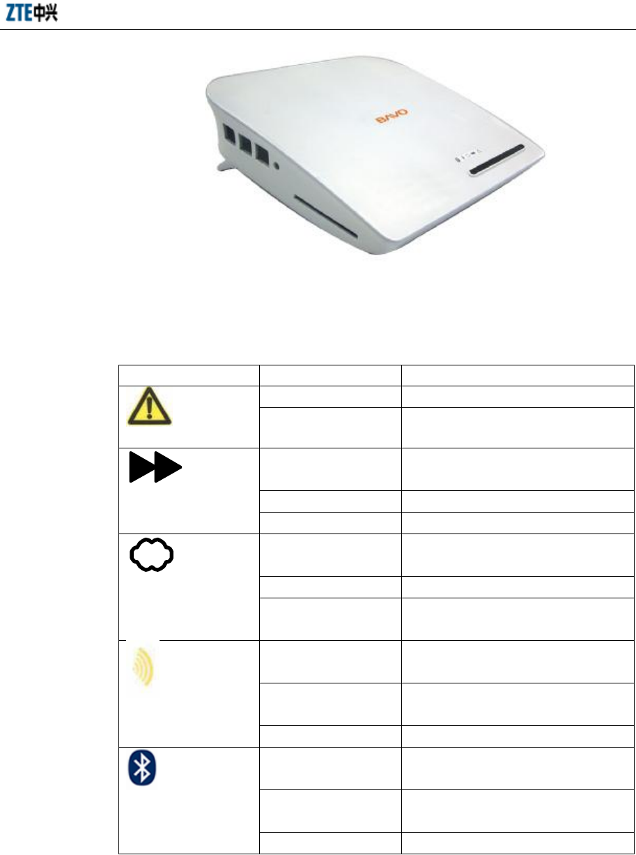
1.4 Appearance of the Product
The planform of the H100 is shown below:
Chapter 1 Introduction of the Product
1-3
The indicators on the front panel of the ZXV10 H100 are shown below:
The meanings of the indicators on the front panel of the ZXV10 H100 are show in the
table below:
Indicators Status Description
On Power-on self-test failure
Fault indicator. Flashing To be determined
The green indicator is
solid on
The device is powered on and the version
is being loaded/upgraded
Off The device is powered off
Run indicator
Flashing The device runs normally
The green indicator is
solid on
The ADSL synchronization is normal and
so is the link connection
Off The link is not set up yet
ADSL LINK indicator
Flashing The link is being set up through
hand-shake negotiation
The green indicator is
solid on
Working (switched on with the WLAN
button)
Off Stops working (switched off with the
WLAN button)
WLAN indicator
Flashing Flashing according to the network traffic
The green indicator is
solid on
Working (switched on with the Bluetooth
button)
Off Stops working (switched off with the
Bluetooth button)
Bluetooth indicator
Flashing Flashing according to the network traffic
The meanings of the indicators on the rear panel of the ZXV10 H100 are show in the
table below:
The meanings of the indicators on the rear panel of the ZXV10 H100 are show in the
ZXV10 H100 Home Gateway User Manual (Draft)
1-4
table below:
Indicators Status Description
The green indicator is solid
on
The physical link connection is normal
Off The device is powered off/the network cable is
unconnected
LAN 1 2 3 4
Flashing Flashing according to the network traffic
On the rear panel of the ZXV10 H100, are two RJ–45 LAN network interfaces, three
RJ–11 interfaces, the reset button and the power supply slot. The details are shown in
the table below:
Buttons Description
Reset button Default functions of the reset button
WLAN button Switch on/off the Wi-Fi function
Bluetooth button Switch on/off the Bluetooth function
1.5 System Requirements
Hardware Requirements
•You need an ADSL modem to access the services provided by the Internet
Service Provider (ISP);
•One PC installed with a 10 Mbps,100 Mbps or 10/100 Mbps Ethernet card;
•If necessary, a Ethernet hub and Ethernet cables can be added to construct a
small and medium Intranet;
Software Requirements
•Each computer accessed into the network should be installed with the network
card driver and the TCP/IP protocol and have correct network settings;
•The H100 has a fixed IP address, or a dynamic IP address allocated from the
DHCP server, or an IP address allocated in the PPPOE dial-up. You also need to
set the gateway server address and the DNS server address provided by your
ISP;
•The Windows 98/Me/2000/NT/Xp or Linux operating system should run
normally;
•One PC of the LAN should be installed with the WEB explorer (Microsoft

Chapter 1 Introduction of the Product
1-5
Internet Explorer 5.0 or later, or Netscape Communicator 4.0 or later) should be
installed in.
2-1
2 System Connections
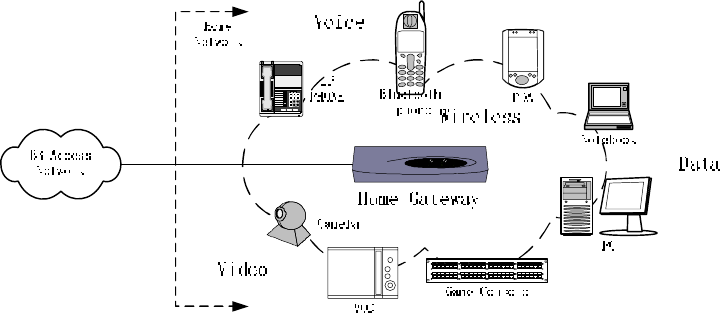
2.1 System Application Environment
The main application environment of the ZXV10 H100 home gateway is shown below:
PWR
OK
WIC0
ACT/CH0
ACT/CH1
WIC0
ACT/CH0
ACT/CH1
ETH
ACT
COL
12 3
45 6
78 9
*8 #
2.2 Connecting the LAN Network Interface
You can connect the H100 to your computer, Ethernet hub or switch. Use one
cross-over or straight-through Ethernet cable to connect the LAN network interface of
the H100 to the network adapter of your PC or other network devices. You can also use
a WLAN wireless RF signal line to connect the H100 to your computer, but the
antenna on the rear panel of the H100 should be put in an ideal direction.
•Connecting your local network through Ethernet cables
Four LAN network interfaces of the H100 can auto-negotiate the connection
speed of the 10 Mbps/100 Mbps Ethernet and the half-duplex/full-duplex
transmission mode. Use a cross-over or straight-through Ethernet cable co
connect any LAN network interface of the H100 to your PC. You cascade the
LAN network interfaces of the H100, connect them to the Ethernet hub or the
Ethernet switch and then connect your PC or other network devices to the hub or
the Ethernet switch.
•Connecting your local network through WLAN
You need to install a wireless network card on your PC in the local network for
ZXV10 H100 Home Gateway User Manual (Draft)
2-2
access to the network through wireless signals and adjust the antenna on the rear
panel of the H100 to the ideal direction to get the effective coverage. You had
better put the H100 in the center of your radio network. Generally, the higher
your antenna is, the better the performance is. Ensure that the H100 is in the
most ideal position in the whole office or home.
•Connecting your local network through USB cables
•Connecting your local network through bluetooth
Warning:
Be sure not to insert the telephone line into any RJ – 45 network interface; otherwise
the H100 will be damaged. Use Ethernet cables with RJ – 45 connectors in compliance
with the CE standard.
2.3 Connecting the WAN (ADSL) Network Interface
2.4 Connecting the Telephone Set
2.5 Connecting the Power Transformer
Use the power transformer to connect the power to the H100 and ensure that the
running indicator on the front panel of the H100 is on.
Warning:
Please use the power transformer provided by us; otherwise the device might be
damaged.
3-1
3 Client Settings
3.1 TCP/IP Installation
If your client PC is not installed with the TCP/IP protocol, please refer to the following
settings:
Click the <Start> button, select [Settings] and then click the [Network and Dial-up
Connections] icon;
Double click the [Local Connections] icon and then click the <Properties> button in
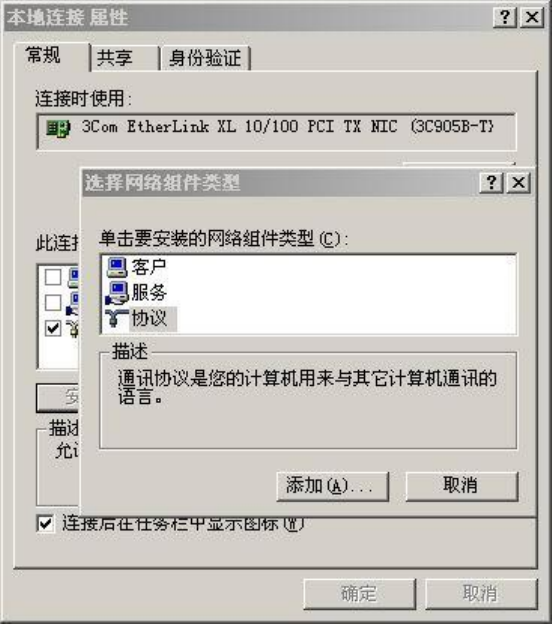
the [Local Connections] tab;
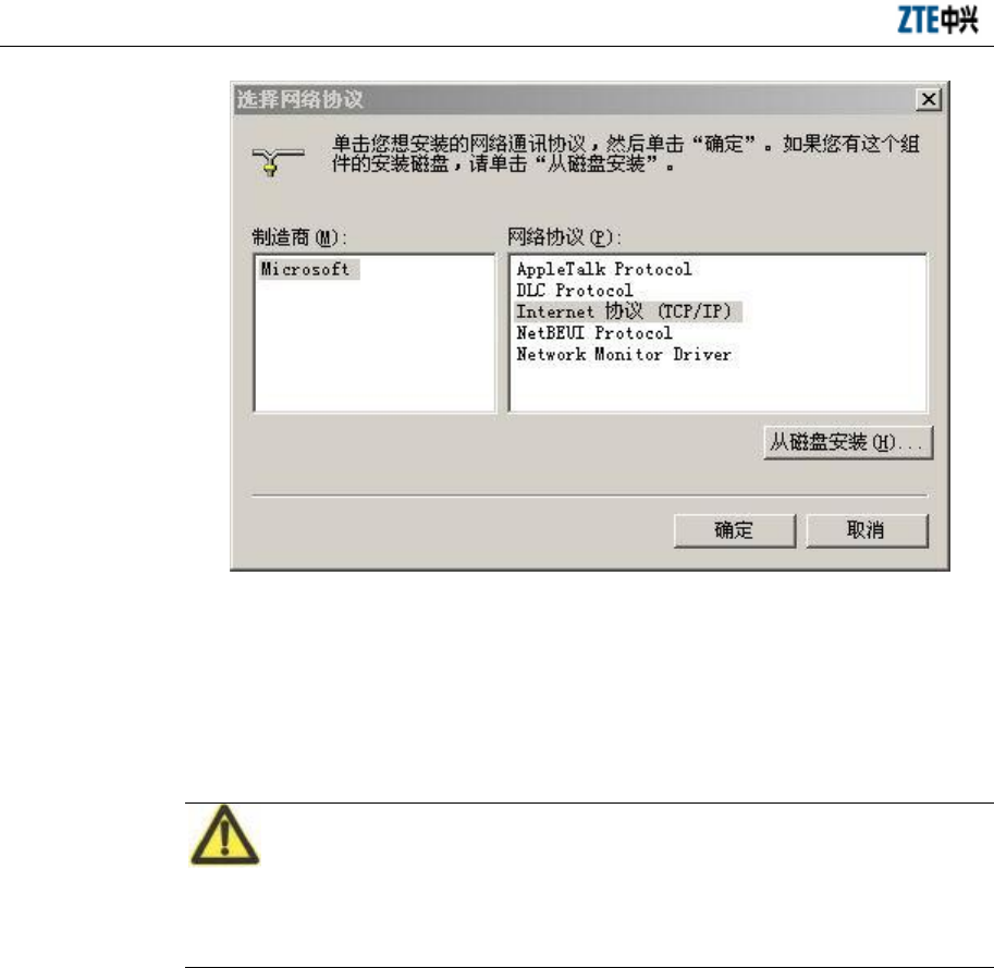
Click the <Install…> button and then double click the [Protocols] icon;
Select [Internet Protocol (TCP/IP)] and then click the <OK> button to finish the
protocol installation.
ZXV10 H100 Home Gateway User Manual (Draft)
3-2
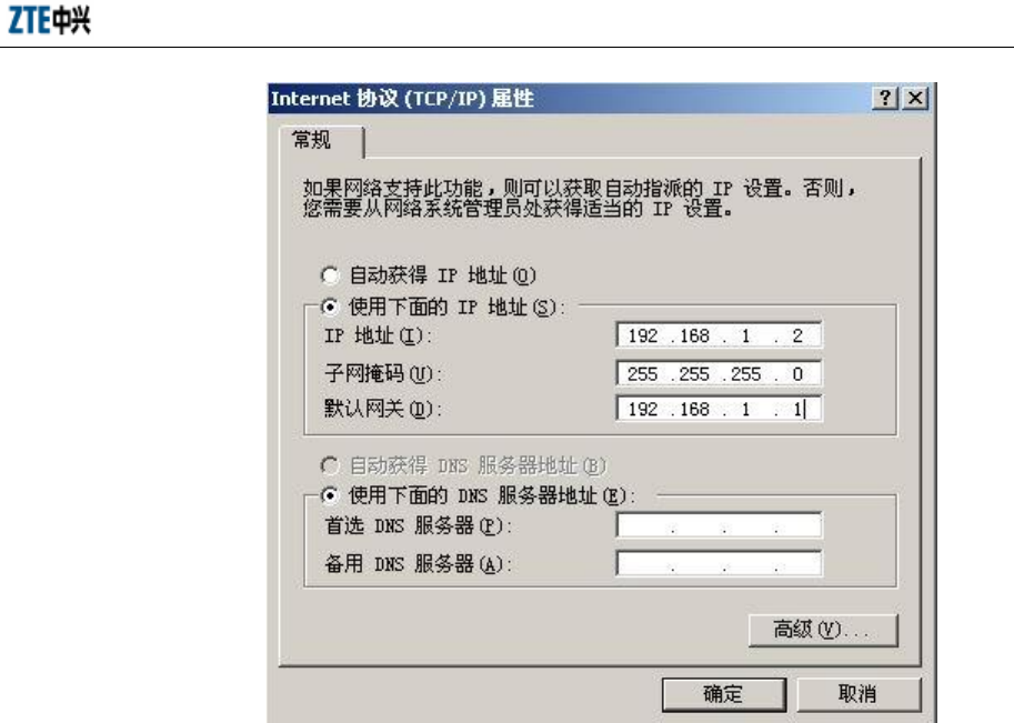
3.2 TCP/IP Configuration
For access to the Internet through the H100, you must configure the PC in the LAN to
be in the same subnet segment with the H100. The default network settings of the H100
are: the IP address of 192.168.1.1 and the subnet mask of 255.255.255.0.
Attention:
The settings are subject to your network requirements. Be sure to install the above
configurations for the first access to the WEB configuration page of the H100.
If your computer is not configured with TCP/IP, set the IP address of the connected
client host to 192.168.1.x (x is within the range of 2 – 254), as shown below. You can
either set the client IP address to be automatically allocated from the DHCP server, or
manually configure it.
Chapter 3 Client Settings
3-3
3.3 Configuration Inspection
After the above preparations, switch on the H100, and you will see that the power
indicator is on. At the same time, the H100 executes the device start-up process and
detects the connected devices. You can see from the indicators which devices have
been connected to the H100 successfully. The indicators of the network interfaces
connecting to successfully connected devices will be solid on.
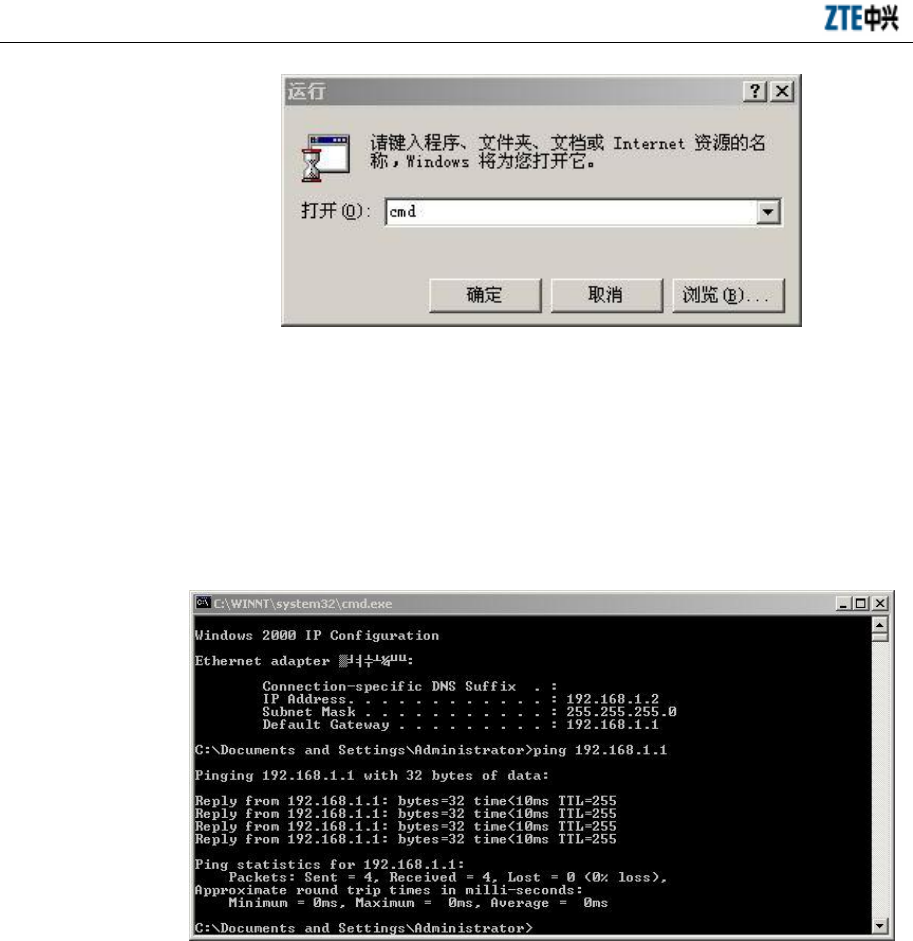
You may also use the PING command to check the network connection status of the PC
and the H100. For example, the steps for connection through the Ethernet interface in
[Local Connections] in the Windows 2000 operating system are as follows:
•Click the [Start→Run] menu;
•Type in “CMD” in the dialog box popped up and then enter;
ZXV10 H100 Home Gateway User Manual (Draft)
3-4
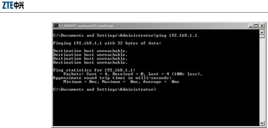
•Type in “ping 192.168.1.1” at the cursor position in the interface popped up and
then enter. If the following information occurs:
Pinging 192.168.2.1 with 32 bytes of data:
Reply from 192.168.2.1: bytes=32 time=2ms TTL=64
the computer has been successfully connected to the H100;
•If the following information occurs:
Pinging 192.168.2.1 with 32 bytes of data:
Request timed out.
Chapter 3 Client Settings
3-5
•An error occurs in the installation. Please check the following items in turn:
Whether the Ethernet cable between the H100 and your PC is correctly
connected.
Whether the network adapter driver on your PC is correctly installed.
Whether the indicators of the LAN interface in the H100 and the network card in
your PC are both on.
Whether the TCP/IP protocol is correctly configured in your PC.
If the IP address of the H100 is 192.168.1.1, the IP address of your PC must be
within the range of 192.168.1.2 - 192.168.1.254, the subnet mask 255.255.255.0
and the default gateway 192.168.1.1.
If you can ping through the H100 successfully, you are well prepared to access the
Internet.

4-1
4 WEB Configuration
The H100 provide configuration tools based on the WEB interface to facilitate
configuration and management through the WEB explorer. For ease of operation, you
can use one cross-over or straight-through Ethernet cable to connect a PC to the
Ethernet interface of the H100 in the first configuration of the H100. Refer to the
section of Configuration Inspection in the above chapter to check whether the TCP/IP
protocol of the PC is set correctly or not, whether any running firewall or security
software needs to be stopped or not and whether the proxy server setting of the
explorer needs to be prohibited or not.
This manual introduces how to configure the H100 with the Internet Explorer 6.0 in the
Windows 2000 Professional operating system.
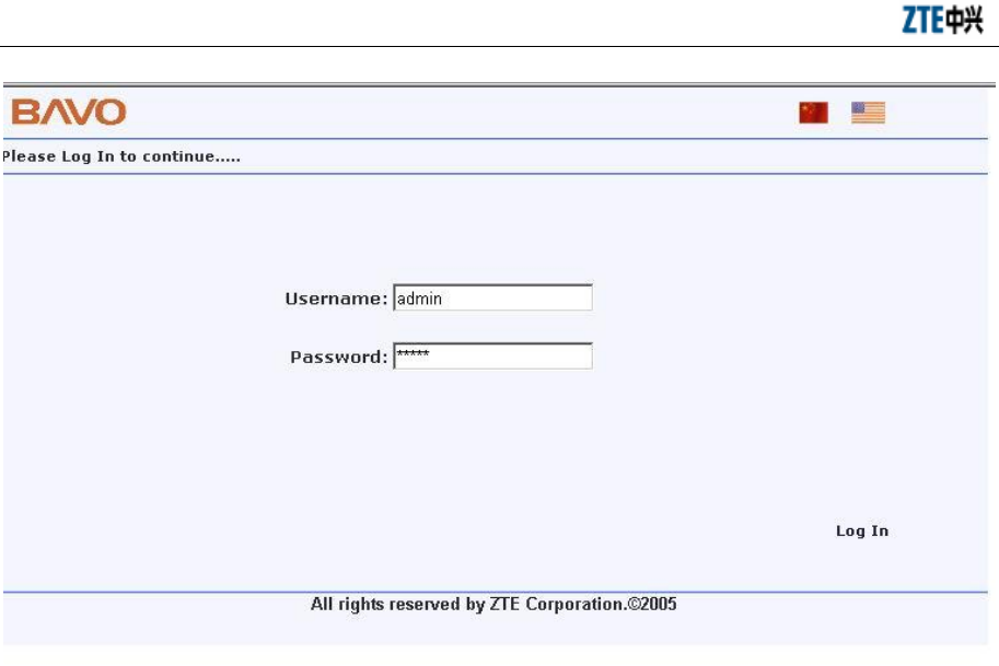
4.1 Main Logon Interface
Open the explorer, input http://192.168.1.1 (the default IP address of the LAN side
interface of the H100 is 192.168.1.1) in the Address URL Editor and then enter. The
logon interface shown below appears. Type in the password to enter the H100
configuration interface (the default WEB logon user name and password are admin
and admin):
ZXV10 H100 Home Gateway User Manual (Draft)
4-2
4.2 Basic Configuration
Click the <Setup> button in the WEB interface to enter the basic configuration of the
H100. In the basic configuration, you can configure the parameters such as LAN
interface parameter, ADSL WAN connection parameter, static route and RIP
dynamic route protocol, DHCP Server and DHCP Relay, DNS Relay, Bridge
connection, STP (Spanning Tree Protocol), SNTP (Simple Network Time Protocol),
SNMP (Simple Network Management Protocol) and WLAN (IEEE802.11b/g)
parameter.
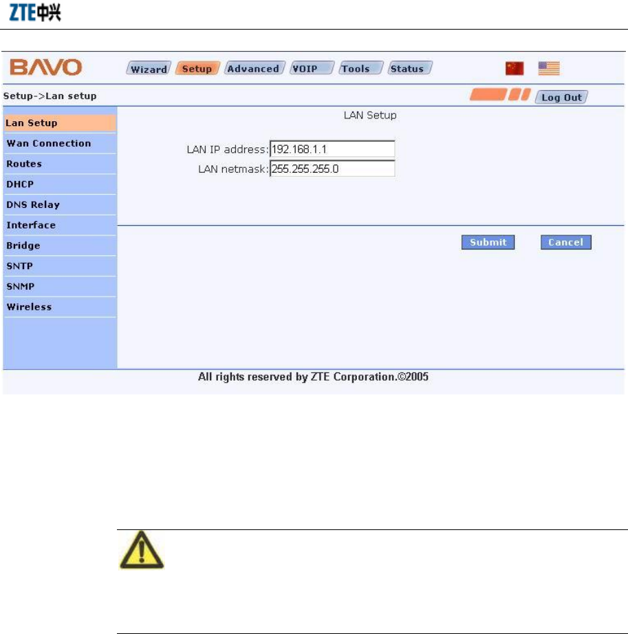
4.2.1 LAN Interface Information
Click the LAN Setup link in the left of the interface to enter the [LAN Setup]
interface, where you can configure the IP address of the Ethernet interface of the H100.
LAN IP address: IP address of Ethernet interface eth0
LAN netmask: Subnet mask of Ethernet interface eth0
Chapter 4 WEB Configuration
4-3
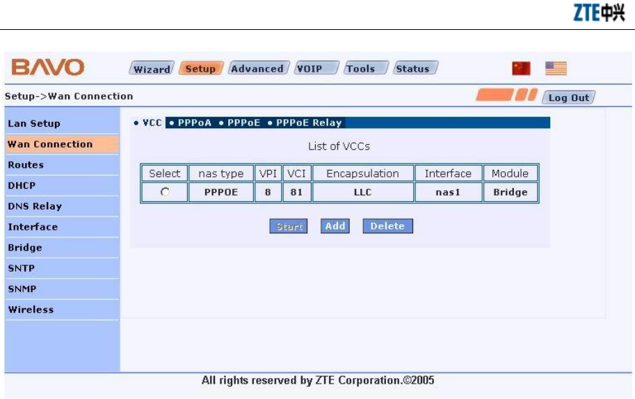
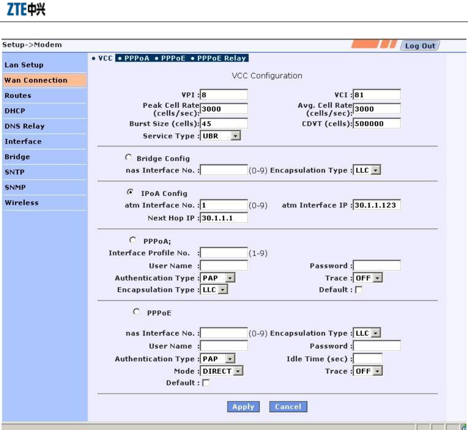
4.2.2 ADSL WAN Connection
Click the WAN Connection link in the left of the interface to enter the [WA N
Connection] interface, where you can set ADSL-based access modes, such as Bridge,
PPPoE, PPPoA and IPoA.
Attention:
For the PPPoE, PPPoA and IPoA connection modes, the Network Address Translation
(NAT) function is activated in the H100 by default.
The first [WAN Connection] interface shows the list of configured VCCs (Virtual
Channel Connection) in the H100. You may use the <Start/Stop>, <Add> and <Delete>
buttons to start/stop, add or delete an ADSL link.
ZXV10 H100 Home Gateway User Manual (Draft)
4-4
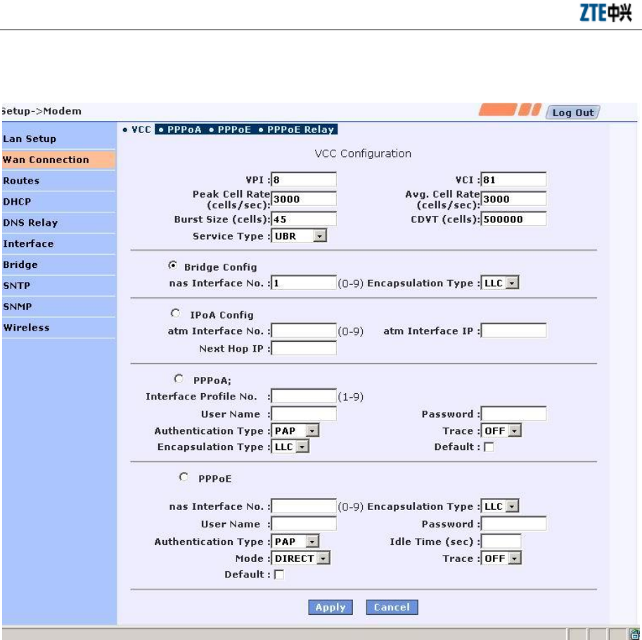
Click the <ADD> button to switch to the WAN connection configuration interface. The
following parameters are the ATM-related configuration parameters of a WAN
connection:
VPI The Virtual Path Identifier is in an 8-bit area of the ATM cell head, indicating
the routed virtual path of the cell. Value range: 0-255
VCI The Virtual Channel Identifier is the unique digital label in a 16-bit area of
the ATM cell head, indicating the virtual channel ID. Value range: 0–255
Peak Cell Rate: Number of cells per second
Average Cell Rate
Service Type QOS type provided by the specific channel
CDVT Cell delay variation threshold.

Chapter 4 WEB Configuration
4-5
4.2.2.1 Bridge (Pure Bridge) Connection
Upon configuration of the ATM-related parameters, select the button in front of Bridge
Config to configure the related parameters of a Bridge (pure bridge) connection.
NAS Interface No. Bridge connection interface No.. The configured No. follows
the character string “nas” when an interface is created, for example nas0, nas1.
Encapsulation Type Value range: LLC/VCC.
Upon configuration of the above parameters, click the <Apply>buttontocreatea
2684Bridged encapsulated nas interface. If you need to set up a Bridge (pure bridge)
connection, the nas interface will act as an interface of the bridge connection and form
a bridge group with another LAN side interface (generally eth0). Refer to the Bridge
interface for the operation of adding to the bridge group. If you need to set up a MER
(MAC Encapsulated Routing) connection, you must configure the IP address of this
ZXV10 H100 Home Gateway User Manual (Draft)
4-6
nas interface in the interface.
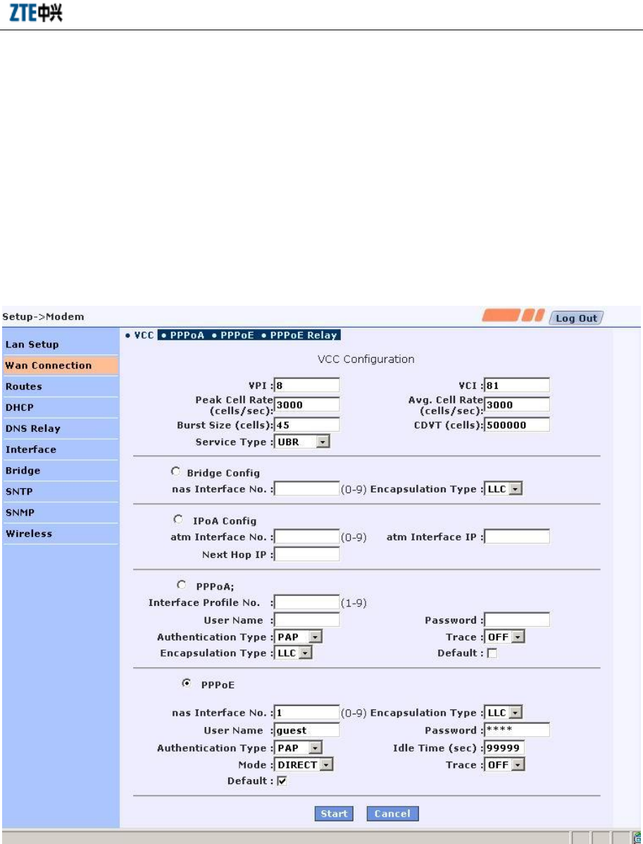
4.2.2.2 PPPoE Connection
If you want to implement the PPPoE dial-up connection through the H100, a PPPoE
connection must be set up. Upon configuration of the ATM-related parameters, select
thebuttoninfrontofPPPoE to configure the related parameters of the PPPoE
connection.
Nas Interface No. Generated 2684 bridge interface No., value range: 0-9.
Encapsulation Type Packet encapsulation type, value range: LLC/VC.
Username&Password PPPoE user name and password to be authenticated.
Authentication type Authentication protocol type, value range: PAP/CHAP.
Idle Time The PPPOE connection should be disconnected after
Chapter 4 WEB Configuration
4-7
becoming idle for a period of time. The idle connection indicates that no packet is
received/sent.
Mode Vale range: DIRECT/AUTO. Selection of DIRECT indicates that the PPPOE
connection is always on line. Selection of AUTO indicates that the functions of idle
timeout and auto-redial triggered by traffic are activated.
Trace Whether the information controlling the session negotiation should be
displayed at the console, value range: ON/OFF.
Default: Select whether a default route is generated.
The PPPOE Session List shows the designated PPPOE sessions that have been
created.
Click the <Stop> button to stop and delete a PPPOE session.

ZXV10 H100 Home Gateway User Manual (Draft)
4-8
Click the <Delete> button to remove the session from the configuration file and stop it.
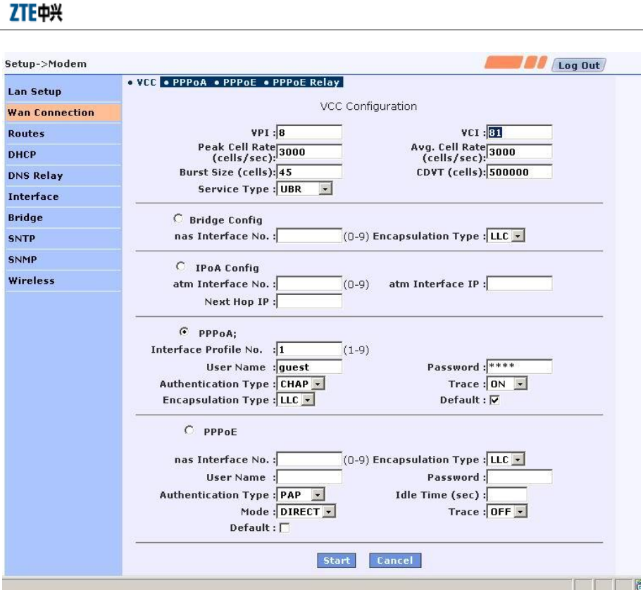
4.2.2.3 PPPoA Connection
If you want to implement the PPPoA dial-up connection through the H100, a PPPoA
connection must be set up. Upon configuration of the ATM-related parameters, select
the button in front of PPPoA to configure the related parameters of the PPPoA
connection. PPPOA (PPP over ATM) is a method for using the PPP protocol on the
ATM network described in RFC 2364.
Interface Profile No. Value range: 0-9.
Username& Password The user name and password to be authenticated.
Authentication type The authentication protocol type, vale range: PAP/CHAP.
Trace Whether the information controlling the session negotiation
should be displayed at the console, value range: ON/OFF.
Encapsulation type Packet encapsulation type, value range: LLC/VC.
Default: Select whether a default route is generated.
Chapter 4 WEB Configuration
4-9
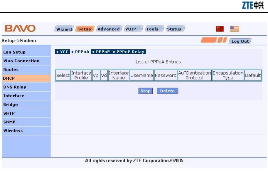
The PPPOA Session List shows the designated PPPOE sessions that have been
created.
Click the <Stop> button to stop and delete a PPPOA session.
Click the <Delete> button to remove the session from the configuration file and stop it.
ZXV10 H100 Home Gateway User Manual (Draft)
4-10
4.2.2.4 IPoA Connection
If your ISP provides the access mode of the IPoA-based static connection, you can
select the IPoA access mode. Upon configuration of the ATM-related parameters, select
the button in front of IPoA to configure the related parameters of the IPoA connection.
ATM Interface No. The configured No. follows the character string “ATM” when
an ATM interface is created, for example atm0, value range: 0.
ATM Interface IP WAN side IP address, the IP address of the ATM interface.
Next Hop IP The IP address of the gateway connecting to the WAN
interface.
Chapter 4 WEB Configuration
4-11
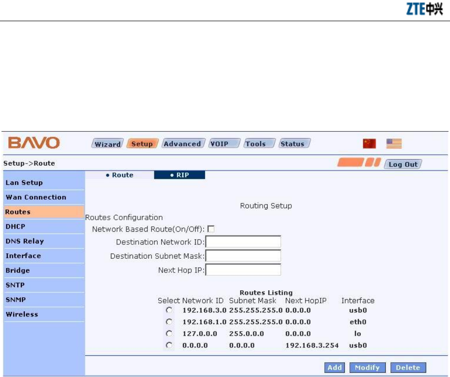
4.2.3 Static Route
Click the Routes link in the left of the interface to enter the route configuration
interface of the H100. In the [Route] tab, you can configure and view the static route
information of the H100. The main interface shows the static route list of the H100.
You can configure a new route, modify or delete the existing routes. The [RIP] tab in
the interface is used to configure the dynamic route protocol RIP of the H100.
If you need to add a new route, designate the destination network ID, subnet mask,
next hop IP and click the <Add> button. Once a route is added, the route list will be
refreshed. To add a host-based route, input the destination network ID and the next hop
IP address. In this case, the [Destination Subnet Mask] option is invalid.
If you need to add a network-based route, please check the [Network Based Route]
checkbox to enable the [Destination Subnet Mask] box and input a proper value.
ZXV10 H100 Home Gateway User Manual (Draft)
4-12
If you need to modify an existing route, select it in the route list. Its configuration is
shown in the set box. Modify the next hop IP address and click the <Modify> button.
If you need to delete an existing route, select it and click the <Delete> button. After
that, the route list is refreshed.
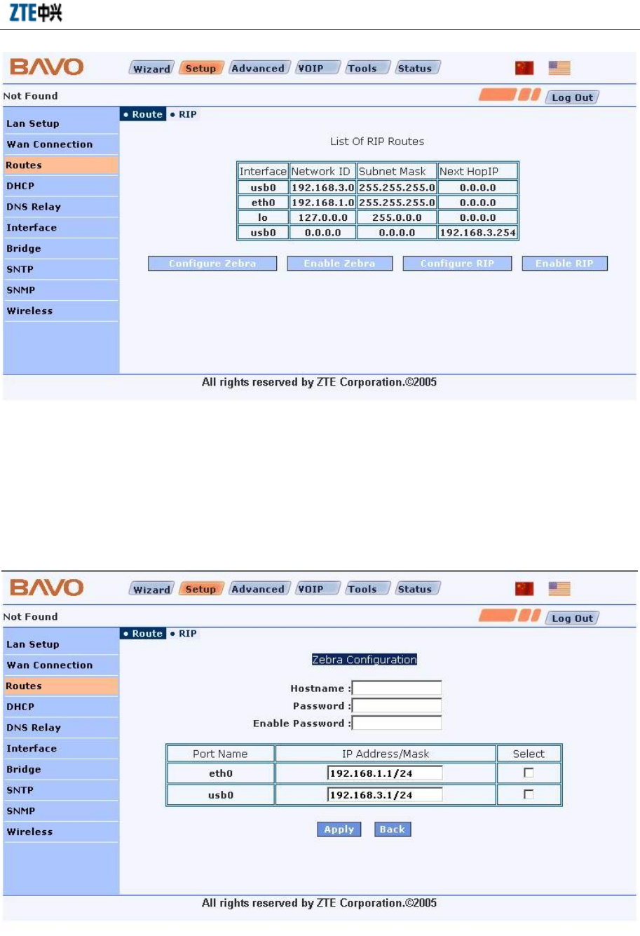
4.2.4 RIP Dynamic Route
Click the [RIP] tab in the main route configuration interface to enter the configuration
interface of the dynamic route protocol RIP, as shown below. The main RIP
configuration interface shows the route table information of the system.
Chapter 4 WEB Configuration
4-13
To activate the RIP function on the H100, you need to configure Zebra and RIP with
the <Configure Zebra> and <Configure RIP> buttons, and then activate the RIP
function with the <Enable Zebra> and <Enable RIP> buttons.
In the Zebra configuration interface shown below, you can configure Hostname,
Password, Enable Password and interface IP address.
ZXV10 H100 Home Gateway User Manual (Draft)
4-14
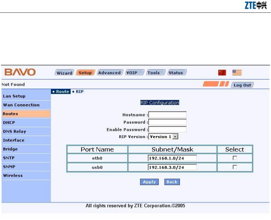
In the RIP configuration interface shown below, you can configure Hostname,
Password, Enable Password and RIP Version (RIP version No.) and the interface where
the RIP is activated.
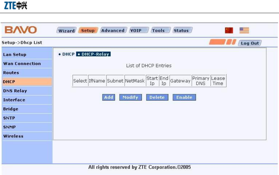
4.2.5 DHCP Server
The DHCP Server List Interface shows the configuration parameters of the current
DHCP server. The DHCP server configuration interface will show up when you click
the <Add>or <Modify> button. In this interface, you can set the configurations of the
DHCP server.
In this interface, you can also Enable or Disable the DHCP server. The content
displayed on the button changes according to the running status of the DHCP server.
“Enable” is displayed in the disabled status and “Disable” is displayed in the enabled
status.
To modify the existing server configurations, select the server, click the <Modify>
button and then complete the modification in the DHCP server configuration interface.
When the related interface is disabled, you can perform the Modify and Delete
operations on the existing server configurations.
Chapter 4 WEB Configuration
4-15
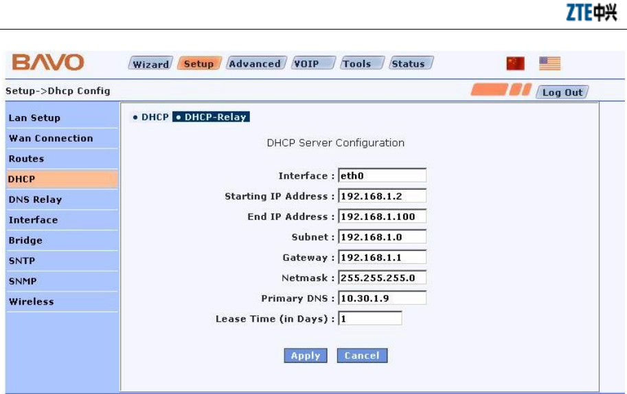
In the DHCP Server Configuration Interface, you can set the configurations of the
DHCP server.
Interface The interface for starting the DHCP server.
Starting IP Address The starting address from the IP address pool allocated by the
DHCP server.
End IP Address The end address from the IP address pool allocated by the
DHCP server.
Subnet The subnet that the IP belongs to.
Gateway The gateway IP address needed for communication of the
DHCP client on the network.
Netmask The subnet mask value.
Primary DNS The main DNS address, the DNS server IP address allocated
to the user to resolve all DNS requests.
Lease Time (In Days) Lease time (unit: day), the period for the DHCP server to
lease IP addresses, range: 1 - 10 days.
ZXV10 H100 Home Gateway User Manual (Draft)
4-16
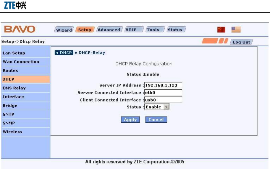
4.2.6 DHCP Relay
The DHCP Relay Configuration Interface shows the status of the DHCP Relay
module and the related configuration parameters.
Status The current status of the DHCP Relay module.
Server IP Address The IP address of the DHCP server.
Server Connected Interface The interface of the H100 connecting to the DHCP server,
whose name should be a valid character string.
Client Connected Interface The interface of the H100 connecting to the DHCP client,
whose name should be a valid character string.
Status Status selection to designate the status of the DHCP Relay function
Chapter 4 WEB Configuration
4-17
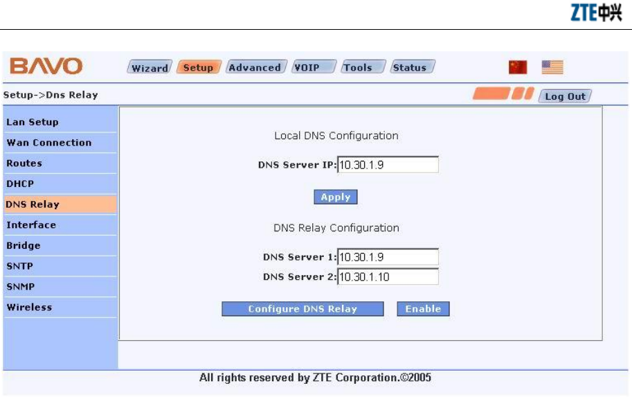
4.2.7 DNS Relay
DNS Relay Configuration Interface:
DNS Server IP The DNS server IP address at the LAN side set in [Local DNS
Configuration] option. Upon configuration, you should click the <Apply> button.
DNS Server 1 and DNS Server 2 When the DNS relay function is configured, the IP
addresses of the DNS servers should be filled in the [DNS Server 1] and [DNS Server
2] boxes. Click the <Configure DNS Relay> button to complete the setting.
DNS Relay To enable the DNS relay function, click the <Enable> button. Upon
enabling of the DNS relay function, the content displayed on the button changes to
Disable.
ZXV10 H100 Home Gateway User Manual (Draft)
4-18
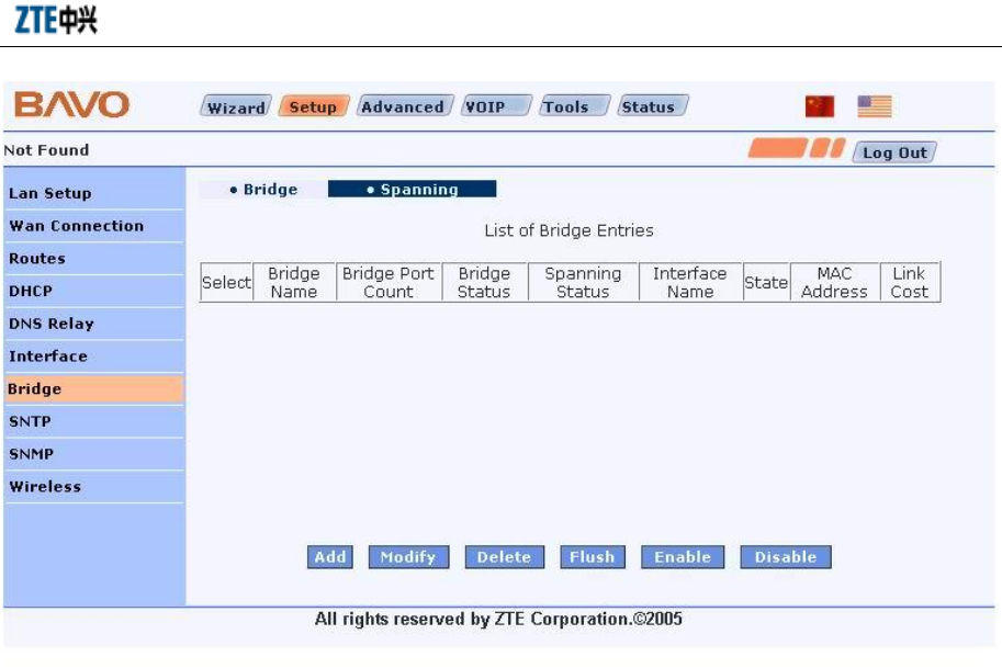
4.2.8 Bridge Connection
Click the Bridge link in the left of the interface to enter the H100 bridge configuration
interface. In this interface, you can create a network bridge interface and configure its
properties and the related properties of the STP protocol.
The main bridge configuration interface shows the list of the existing bridge interfaces.
Select a bridge interface and click the <Modify/Delete/Enable/Disable> button to
modify, delete, enable or disable it.
Chapter 4 WEB Configuration
4-19
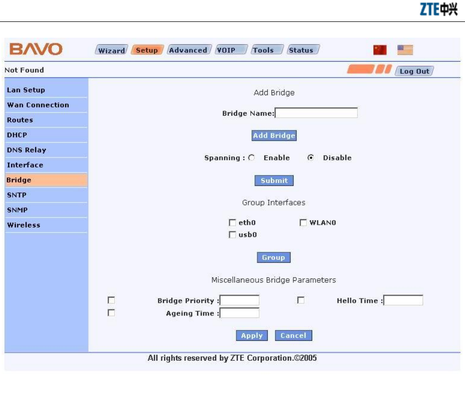
Click the <Add> button to enter the interface for creating a network bridge interface, as
shown below. In this interface, you can designate the name of the bridge interface to be
created (Bridge Name), add the LAN side interface to the bridge group as a bridge
interface, or configure whether to enable the STP protocol or not (STP is enabled if
Spanning is Enable; it is disabled if Spanning is disabled).You can also configure the
parameters of the network bridge, such as Bridge Prioriry, Hello Time and Ageing
Time.
ZXV10 H100 Home Gateway User Manual (Draft)
4-20
Click the [Spanning] tab in the bridge configuration interface to enter the STP
parameter configuration interface, as shown below. In this interface, you can configure
the Link Cost property of the member ports in the network bridge.