ZTE QP 100_A6 1208 Qp100
User Manual: ZTE qp100
Open the PDF directly: View PDF ![]() .
.
Page Count: 4
MODEL
Output
Output Number
QP-100-G QP-100-GB
Rated Current
Current Range
Rated Power
Ripple & Noise (max.)
Voltage Adj. Range
Voltage Tolerance
Line Regulation
Load Regulation
Setup, Rise Time
Hold up Time (Typ.)
CH1 CH2 CH1 CH2 CH3 CH1 CH2 CH1 CH2 CH3
13.8V 13.8V 13.8V 13.8V 5V 27.6V 27.6V 27.6V 27.6V 5V
5.3A 2A 4.2A 2A 3A 2.15A 1.5A 1.6A 1.5A 3A
0~7A --------- 0~6.5A 0~3.2A 0~3.4A 0~3.3A 0~3.2A
100.74W
100mV 100mV 100mV 100mV 100mV 100mV
CH1:10%
±1% ±1% ±3% ±1% ±1% ±3%
±0.5% ±0.5% ±0.5% ±0.5% ±0.5% ±0.5%
800ms, 50ms/230VAC 800ms, 50ms/115VAC at full load
Input
Voltage Range
Frequency Range
Efficiency (Typ.) at 230Vac
AC Current (Typ.)
Inrush Current (Typ.)
Leakage Current
90 ~ 264VAC 127 ~ 373VDC (Withstand 300VAC surge for 5sec. Without damage)
2A /115VAC 1.2A / 230VAC
Cold Start 35A / 115VAC 70A / 230VAC
Protection
Over Load
Over Voltage
Above 110% rated output power
Protection type : Hiccup mode, recovers automatically after fault condition is removed
115% ~ 140% rated output voltage
Protection type : latch-off mode
Environment
Working Temp.
Working Humidity
Storage Temp., Humidity
Temp. Coefficient
Vibration
-20°C ~ +70°C (Refer to output load de-rating curve)
20 ~ 90% RH non-condensing
-40 ~ +85°C, 10 ~90%
±0.03%/°C (0 ~ 50°C) on CH1
10 ~ 500Hz, 2G 10min./1 cycle, period for 60 min. each along X,Y,Z axes
Safety & EMC
Safety Standards
EMI Conduction & Radiation
Isolation Resistance
EMS Immunity
Harmonic Current
Withstand Voltage
Meet UL60950-1 / TUV EN60950-1 Approved
I/P - O/P : 3KVAC I/P - FG : 1.5KVAC O/P-FG : 0.5KVAC
EN55022 : 2006+A1:2007 Class B
I/P - O/P: 100M Ω / 500VDC
EN61000-4-2,3,4,5,6,8,11; ENV50204; EN55024
EN61000-3-2 :2006 Class A, EN61000-3-3 : 1995+A1 : 2005
Others
MTBF
Battery cut off 10V±4%
Packing
Dimension (L*W*H)(mm)
123x95x31mm
1. All parameters NOT specially mentioned are measured at 230VAC input, rated load and 25°C of ambient temperature.
2. Ripple & noise are measured at 20MHz of bandwidth by using a 12" twisted pair-wire terminated with a 0.1uf & 47 uf parallel capacitor.
3. Tolerance: includes set up tolerance, line regulation and load regulation.
4. Line regulation is measured from low line to high line at rated load.
5. Load regulation is measured from 0% to 100% rayed load.
6. The power supply is considered a component which will be installed into a final equipment. The final equipment must be re-confirmed that it still
meets EMC directives.
7.Length of aet up time is measured at cold first start. Turning ON/OFF the power supply very quickly may lead to increase of the set up time.
Note
DC Voltage Range
50ms / 230VAC 10ms /115VAC at full load
QP-100-LBQP-100-L
±0.5% ±0.5% ±1% ±0.5% ±0.5% ±1%
--------- --------- ---------
100.56W 100.74W 100.56W
CH1:10%
--------- --------- ---------
---------
--------- --------- ---------
---------
--------- --------- ---------
---------
47Hz ~ 63Hz
86% 85% 87% 85%
For earth <1mA / 264VAC
20V±5%
Function AC OK
BAT Low
TTL open collector output Relay contact output TTL open collector output Relay contact output
Battery low voltage <12V±3% Battery low voltage <22V±3%
--------- --------- --------- ---------
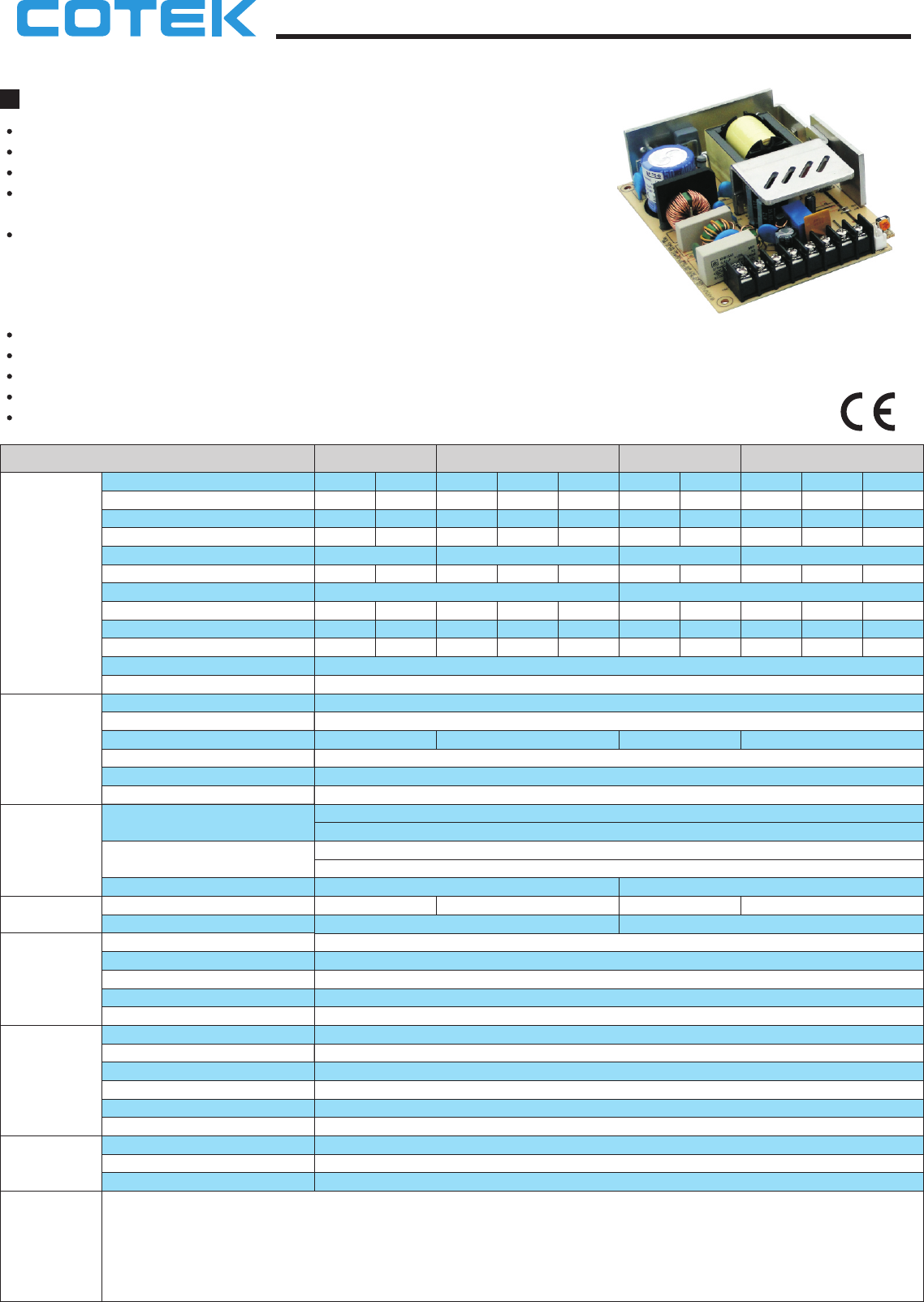
100W 1~3 Output with battery Charger QP-100 series
Features :
Universal AC input / Full range
Protections: Short circuit / Over load / Over voltage
Brown-out (Low AC Input Voltage)
Battery low protection
High efficiency, long life and high reliability
3 years warranty
Withstand 2G vibration test
Alarm signal for AC OK and Battery low
(TTL open collector output or Relay contact output)
All using 105°c long life electrolytic capacitors
Battery polarity protection
Auto switch when power off (UPS function)
Built-in constant current limiting circuit
(by Resettable Fuses)
Cooling by free air convection
REV. A6
10/12/08
1
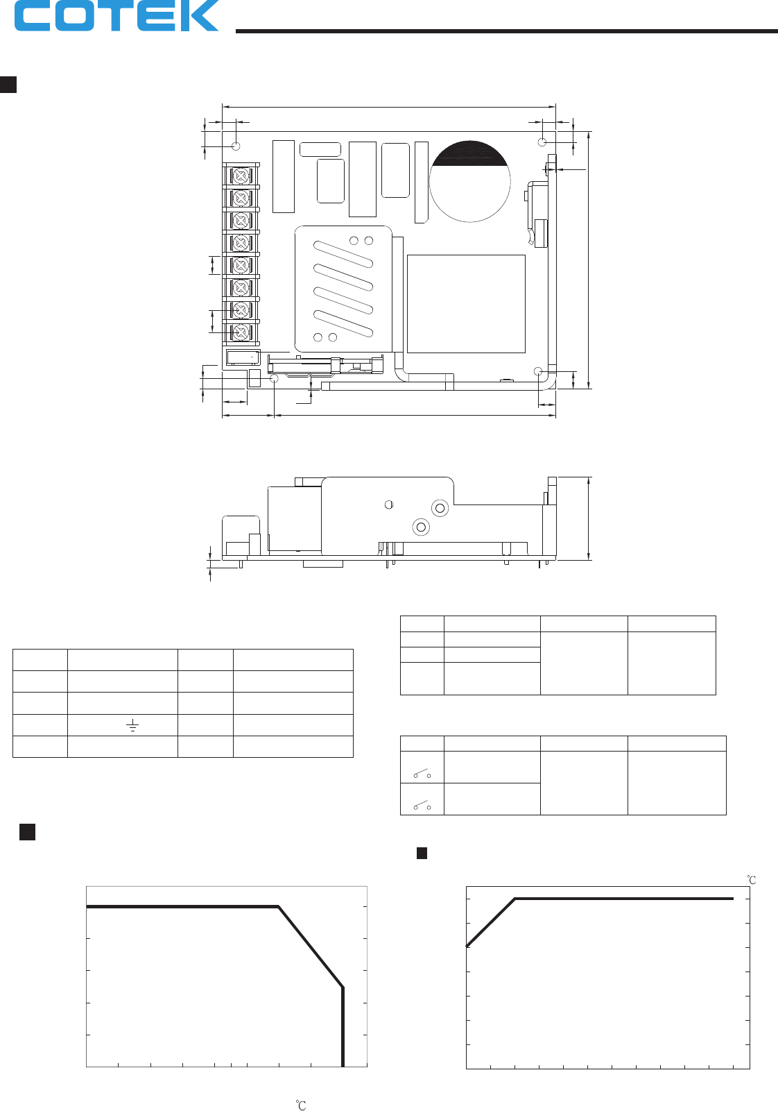
Mechanical Specification
Unit:mmUnit:mm
Terminal Pin No. Assignment(CN1)
Pin No. Assignment Pin No. Assignment
1
2
3
4
AC/L
AC/N
DC Output com
FG
5
6
7
8
DC output V+
BAT+
BAT-
DC/DC Output +5V
(GB/LB only)
Mechanical Specification
Output Derating VS Input Voltage
INPUT VOLTAGE (VAC) 60Hz
90 10095 120115 160140 200180 240220 264
LOAD (%)
Ta=25
90
100
80
70
60
50
40
AMBIENT TEMPERATURE ( )
LOAD (%)
-20 0 2010 30 35 40
20
40
80
60
100
6050 70 (HORIZONTAL)
Alarm output Connector(CN2): JST B3B-XH or equivalent
Pin No.
1
2
3
Assignment
AC OK
BAT LOW
Mating Housing
JST XHP-3
or equivalent
Terminal
SXH-001 T-P0.6
Pin No.Assignment
AC OK
Mating Housing
JST XHP-4
or equivalent
Terminal
12
34Bat. Low or equivalent
QP-100-G/L
QP-100-GB/LB
JST
SXH-001 T-P0.6
JST
Alarm output Connector(CN2): JST B4B-XH or equivalent
or equivalent
G (13.8V/20mA)
L (27.6V/20mA)
8.25 6.65
4
5.5
0.2
3
31
CN1
1
2
3
4
5
6
7
8
CN2
9
19.1 103.9
3.9
6.5
6.5
0.4
95
5 5
123
100W 1~3 Output with battery Charger QP-100 series
REV. A6
10/12/08
2
CN2
1
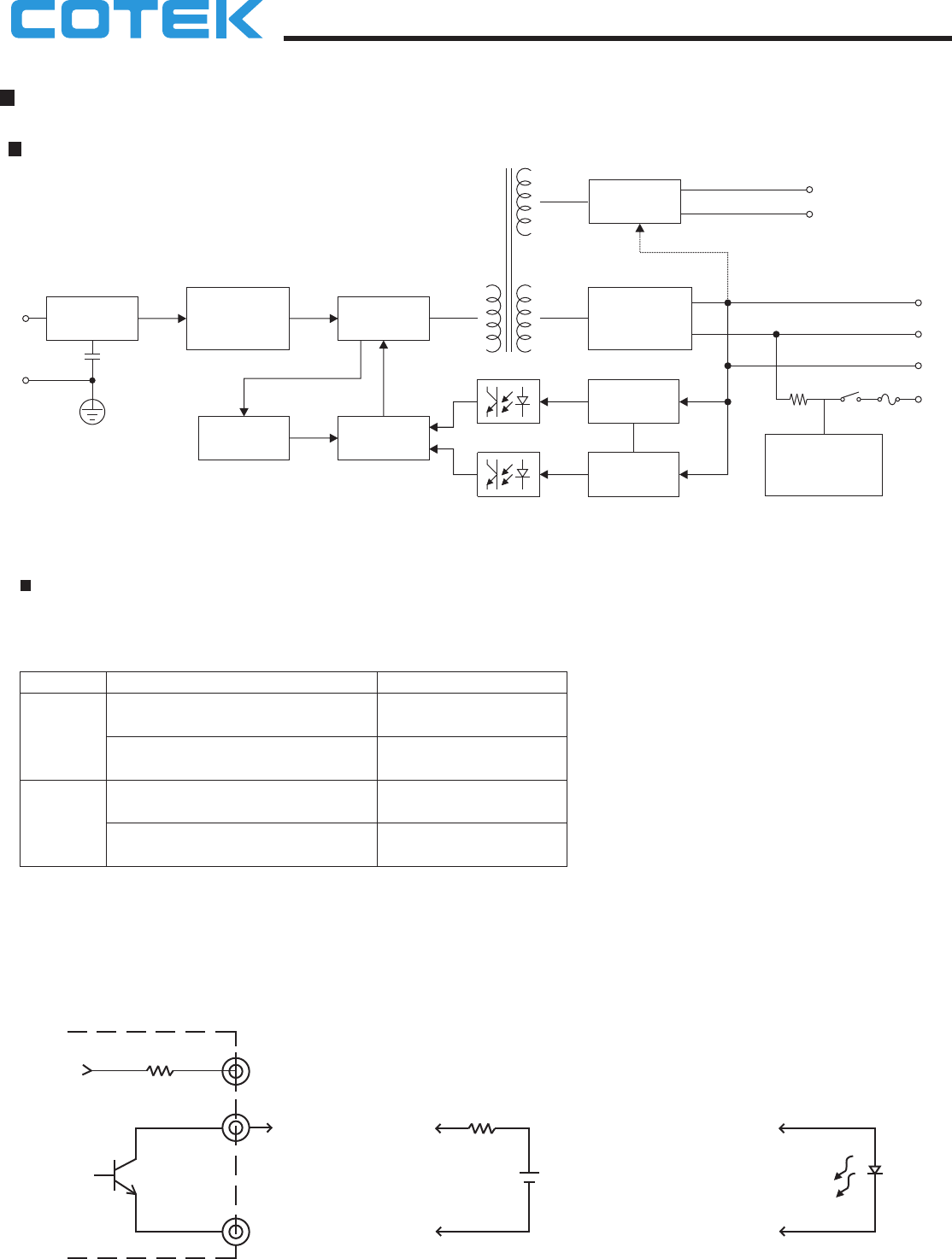
Block Diagram
EMI FILTER
RECTIFIER
&
FILTER
POWER
SWITCHING
O.L.P. PWM
CONTROL
DETECTION
CIRCUIT
O.V.P.
RECTIFIERS
&
FILTER
Battery Charger
&
Back up Control
V+
COM
B+
B-
I/P
FG
ALARM
CIRCUIT
AC OK
Bat. Low
For QP-100-G/L
Alarm Signal for AC OK and Battery Low
(1) Alarm Signal is sent out through " AC OK " & " Battery Low " pins.
(2) An external voltage source is required for this function.The maximum applied voltage is 50V and the maximum sink current is 30mA.
(3) Table3 .1 explain the alarm function built-in the power supply
Function Output of alarm
(0.3V max. at 30mA)
(0.3V max. at 30mA)
voltage 30mA max.)
voltage 30mA max.)
Low
Low
High or open(External applied
High or open(External applied
Description
The signal is "Low" when the power supply
The signal is "Low" when the voltage of
The signal is "High" when the voltage of
The signal turns to be "High" when the power
turns on
battery is under G:12V , L:22V
battery is above G:12V , L:22V
supply turns OFF
AC OK
Battery
Low
Table 3.1 Explanation of Alarm Signal
External voltage and R
(The max. Sink is 30mA and 50V)
R
V
AC OK (Battery low)
Internal circuit of AC OK (Battery Low)
V+
or
CN1 Pin4 DC output com
CN2 Pin3
CN2 Pin1(Pin2)
CN2 Pin1(Pin2)
CN2 Pin3
G: 13.8V/20mA
L: 27.6V/20mA
100W 1~3 Output with battery Charger QP-100 series
REV. A6
10/12/08
3
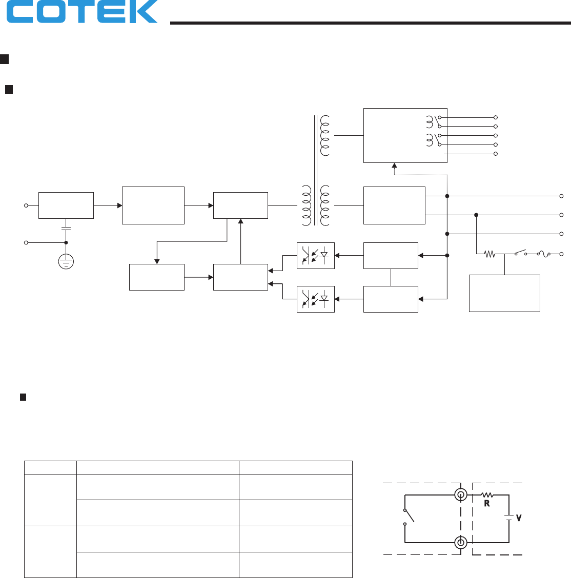
Alarm Signal for AC OK and Battery Low
(1) Alarm Signal is sent out through " AC OK " & " Battery Low " pins. (relay contact type)
(2) An external voltage source is required for this function.The maximum applied voltage is 30V and the maximum sink current is 1 A.
(3) Table 4 .1 explain the alarm function built-in the power supply
Function Output of alarm
voltage 1A max.)
voltage 1A max.)
Low or short
High or open(External applied
High or open(External applied
Description
The signal is "Low" when the power supply
The signal is "Low" when the voltage of
The signal is "High" when the voltage of
The signal turns to be "High" when the power
turns on
battery is under GB:12V , LB:22V
battery is above GB:12V , LB:22V
supply turns OFF
AC OK
Battery
Low
Table 4.1 Explanation of Alarm Signal
EMI FILTER
RECTIFIER
&
FILTER
POWER
SWITCHING
O.L.P. PWM
CONTROL
DETECTION
CIRCUIT
O.V.P.
RECTIFIERS
&
FILTER
Battery Charger
&
Back up Control
V+
COM
B+
B-
I/P
FG
ALARM
CIRCUIT
&
SWITCHING
FILTER
AC OK
Bat. Low
+5V
ALARM
CIRCUIT
&
SWITCHING
FILTER
For QP-100-GB/LB
Low or short
AC OK(Battery low)
CN2 Pin1(Pin3)
Externalvoltagesource(V)
andresistor(R)
(Themax.Sinkis1A and30V)
lnternalcircuitof AC OK(BatteryLow)
CN2 Pin2(Pin4)
Block Diagram
100W 1~3 Output with battery Charger QP-100 series
REV. A6
10/12/08
4
