ZUNIDATA SYSTEMS AD1000 POS system User Manual rev2
ZUNIDATA SYSTEMS, INC POS system rev2
UserManual.wiki
>
ZUNIDATA SYSTEMS
>
AD1000 User Manual
User Manual_rev2.pdf
Navigation menu
Upload a User Manual
Namespaces
Wiki Guide
HTML
PDF
Info
Views
User Manual
Discussion / Help
Navigation
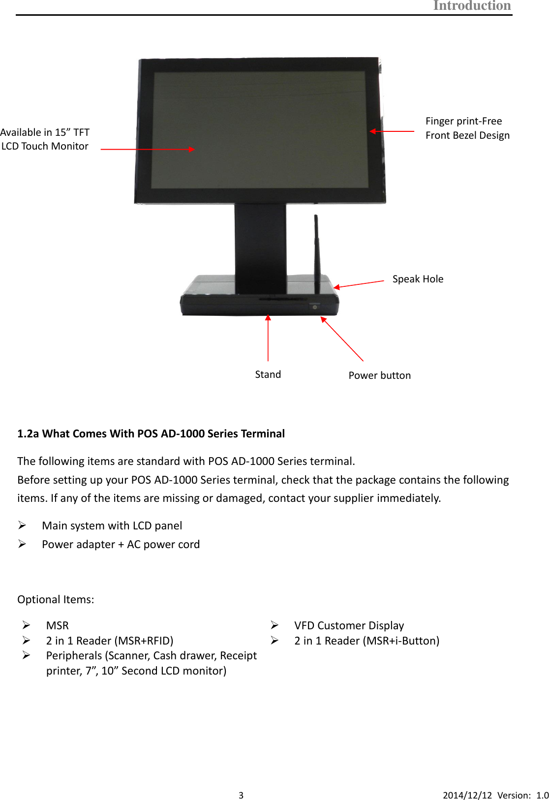
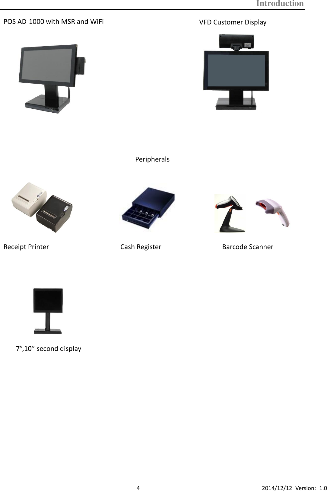
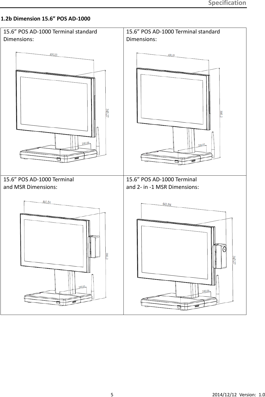
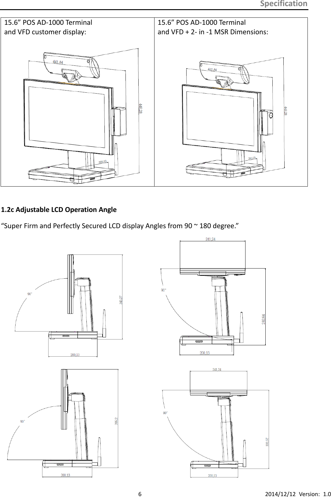
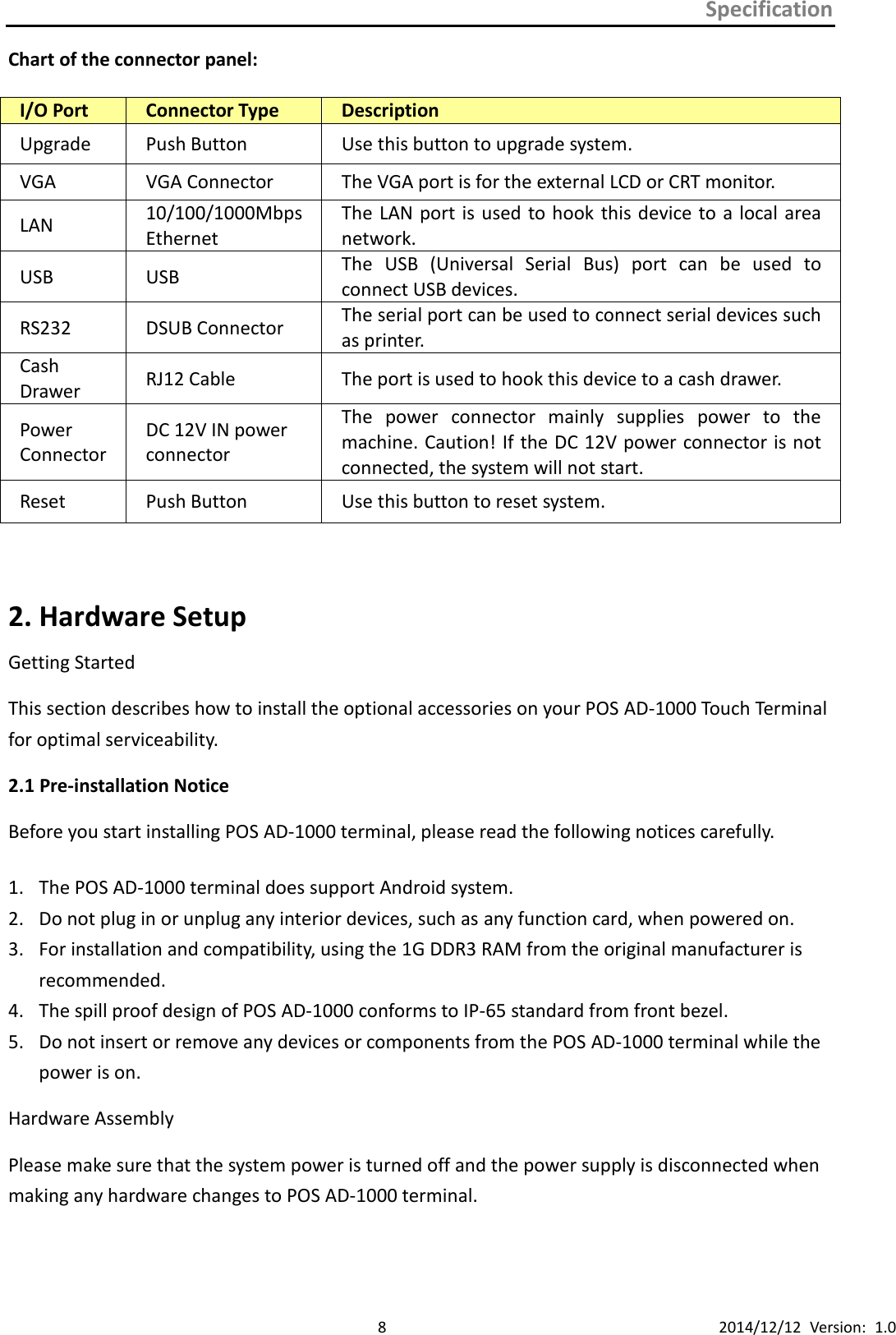
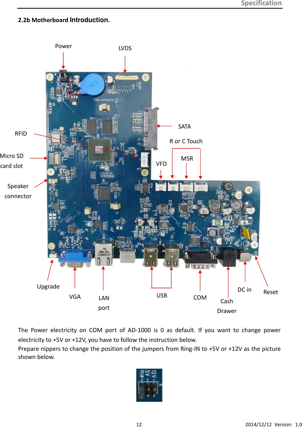
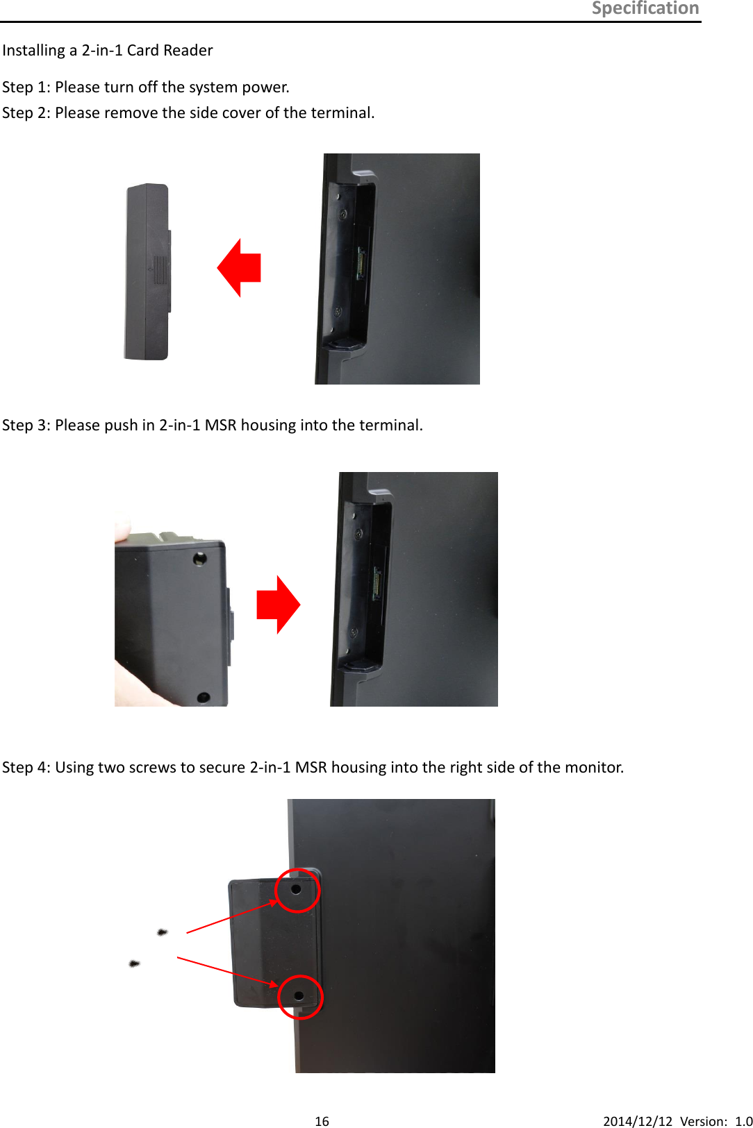
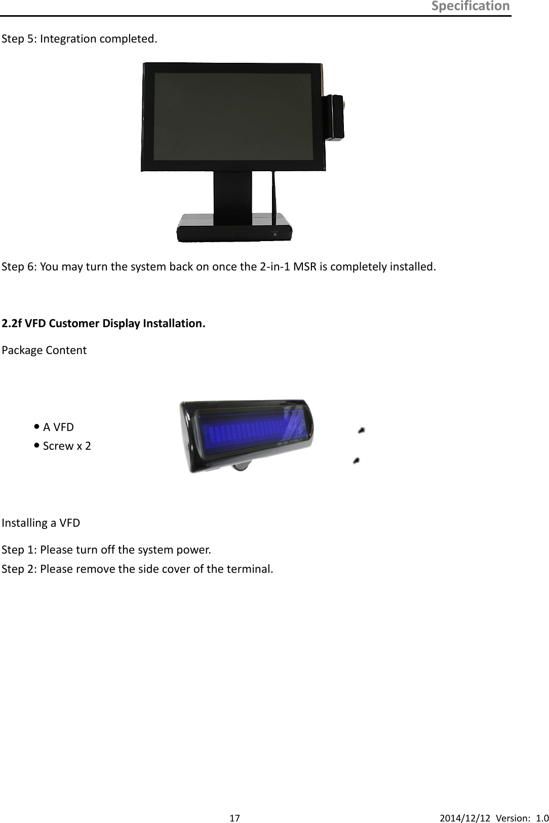
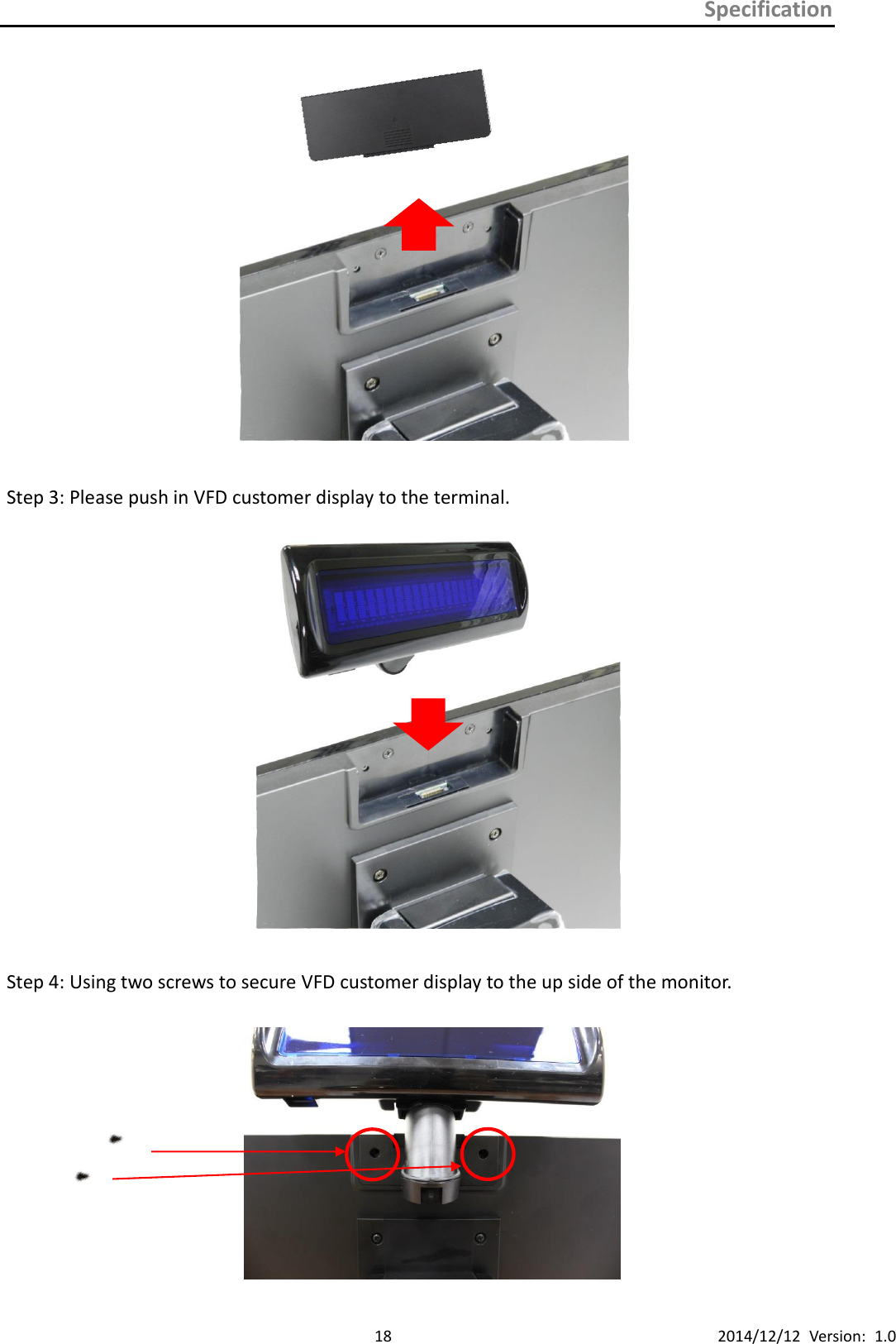
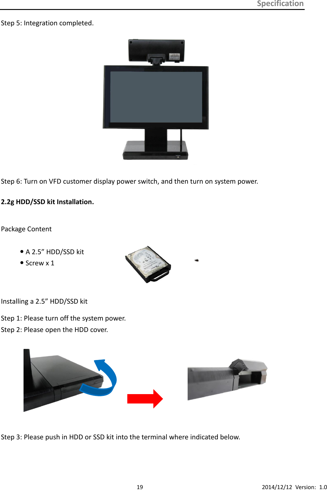
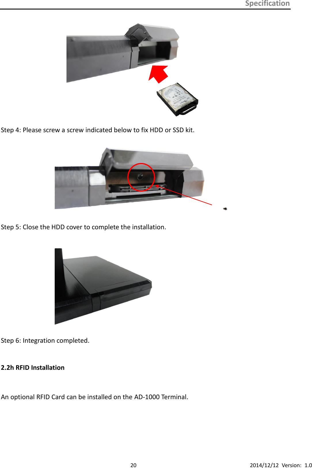
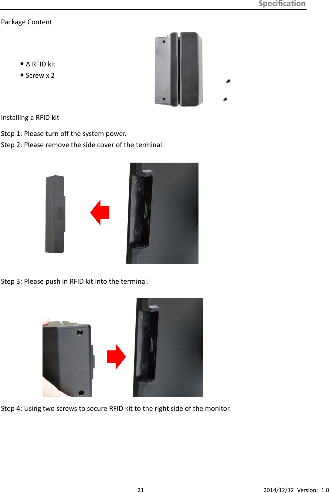
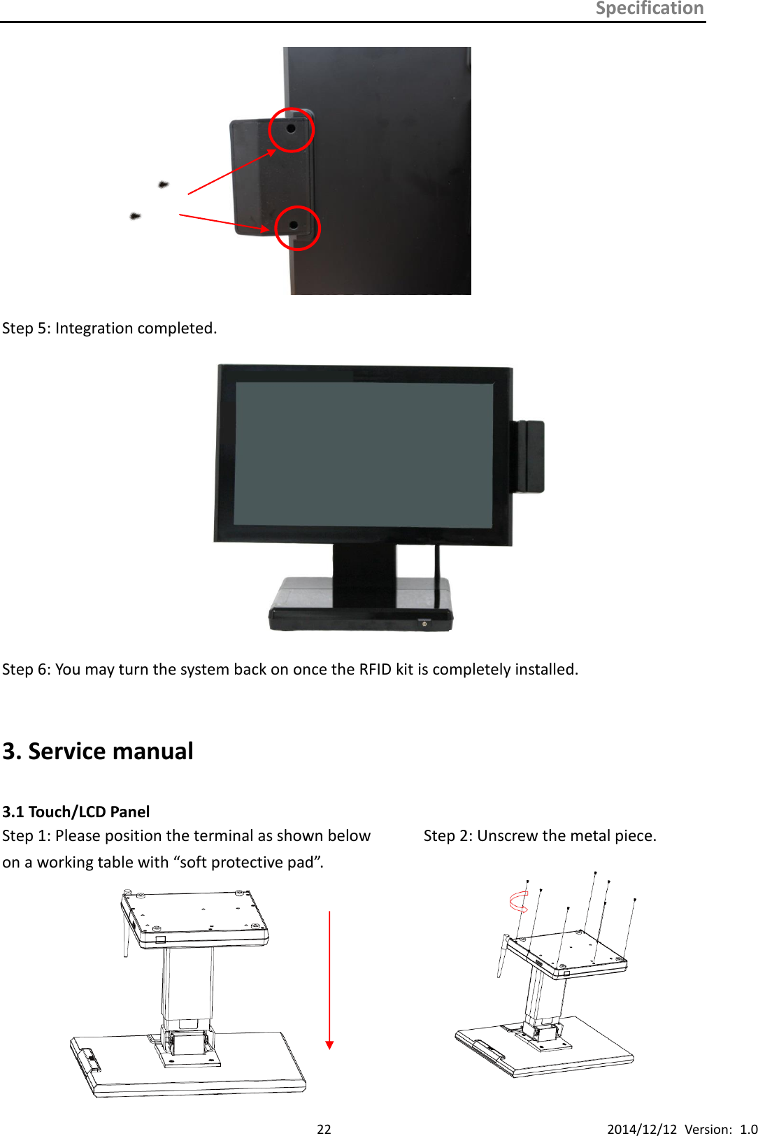
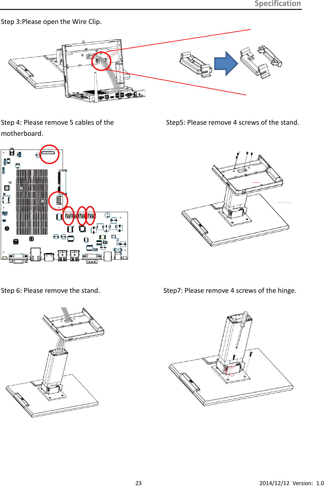
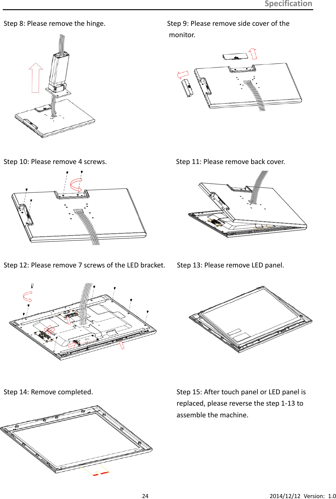
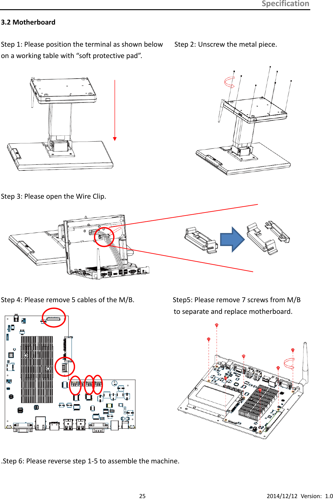
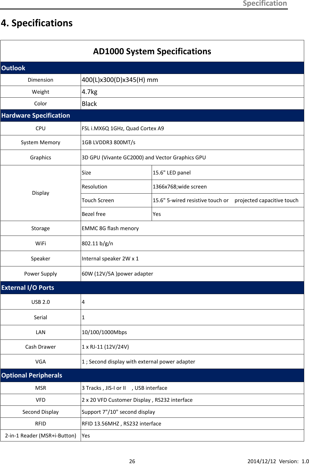
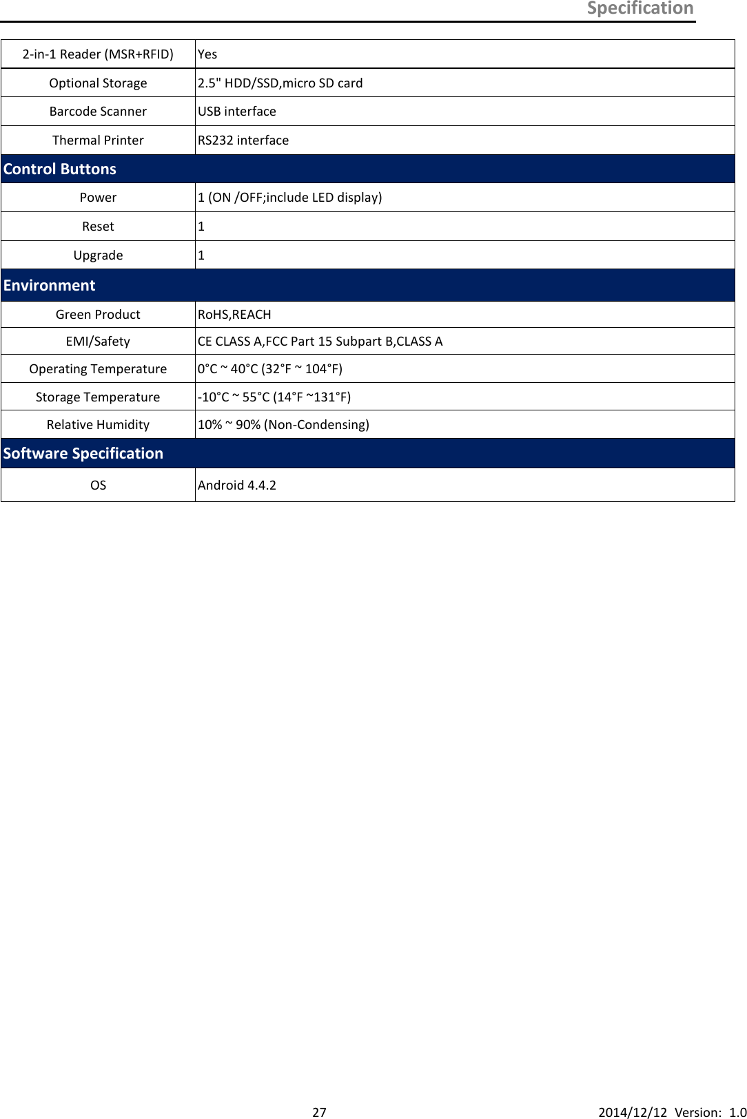
![Specification 7 2014/12/12 Version: 1.0 1.3 Features POS AD-1000 Series terminal comes equipped with the following features: Low power consumption LV (Low Voltage) design of the device is embedded with a unique chipset renders power saving function. Saving cost of ownership Modular design provides the owner with the following benefits: (a) cost effectiveness, (b) customization flexibility, and (c) Easy maintenance. Compact size/Aesthetic design Slimmest in the POS industry standard [Standard: 400(W) x 200(D) x 345(H) mm, Highest: 400(W) x 200(D) x 395(H) mm]. This elegant, economic POS system feathers a sleek, compact design base that saves counter space and adds appeal to the service environment. Dust/water proof AD-1000 features a highly durable, rigorously tested design that is reliable and dependable in rugged environments. Environment protection Environmental friendly, RoHS compliant product. High Stability The AD-1000 has a longer overall system MTBF to provide a higher stability during operation. 1.4 Connector Panels The connector panel is located at the bottom of the main unit base. To clearly see the panel you must open the base cover. Upgrade VGA LAN USB RS232 Cash Drawer DC-in Reset](https://usermanual.wiki/ZUNIDATA-SYSTEMS/AD1000/User-Guide-2558483-Page-13.png)