ZUNIDATA SYSTEMS AD1000 POS system User Manual rev2
ZUNIDATA SYSTEMS, INC POS system rev2
User Manual_rev2.pdf
Flexible / Classy / High Performance
POS AD1000 Series
USER’S MANUAL
Android POS systems
Freescale i.MX6 Dual/Quad Core Processor technology
Version: 1.1
Date: December 25, 2014

Preface
2014/12/12 Version: 1.0
ii
About this Manual
Thank you for purchasing POS AD-1000 Series All-in-One system. This terminal offers all the
enhanced features and is easy to connect to various optional devices for optimal performance.
This user manual describes how you setup and connect your terminal.
Copyright
The information in this guide is subject to change without prior notice.© Copyright 2014
All rights reserved. This product and related documentation are protected by copyright and are
distributed under licenses restricting their use, copying, and distribution. No part of this
documentation may be reproduced in any form by any means without prior written
authorization of the manufacturer and its licensors, if any.

Preface
2014/12/12 Version: 1.0
iii
Federal Communications Commission (FCC)
Declaration of Conformity
This device complies with part 15 of the FCC Rules. Operation is subject to the following two
conditions:
1. This device may not cause harmful interference.
2. This device must accept any interference received, including interference that may cause
undesirable operation.
This equipment has been tested and found to comply within the limit of a Class A digital device,
pursuant to Part 15 of the FCC Rules. These limits are designed to provide reasonable protection
against harmful interference in a residential installation. This equipment generates, uses, and can
radiate radio frequency energy and, if not installed and used in accordance with the instructions,
may cause harmful interference to radio communications. However, there is no guarantee that
interference will not occur in a particular installation. If this equipment does cause harmful
interference to radio or television reception, which can be determined by turning the equipment
off and on, the user is encouraged to try to correct the interference by one or more of the
following measures:
Reorient or relocate the interference receiving antenna.
Increase the distance of separation between the equipment and interference receiver.
Connect the equipment to a power outlet on a circuit different from that to which the
interference receiver is connected.
Consult the dealer or an experienced radio/TV technician for help.
WARNING:
Use the included AC power cord so as not to interfere with radio and television reception.
If you use other cables, it may cause interference with radio and television reception.
WARNING:
TO PREVENT FIRE OR SHOCK HAZARD, DO NOT EXPOSE THIS APPLIANCE TO RAIN OR MOISTURE.
WARNING:
This is a equipment of Class A. This device could cause interferences in residential areas; in the case of interferences
it can be demand from the user to provide appropriate solutions for it.
WARNING:
The use of shielded cables for connection of the monitor to the graphics card is required to assure compliance with
FCC regulations. Changes or modifications to this unit not expressly approved by the party responsible for
compliance could void the user’s authority to operate this equipment.
RoHS
This device complies with Part 15 of the FCC Rules. Operation is subject to the following two
conditions: (1) This device may not cause harmful interference, and (2) this device must accept
any interference received, including interference that may cause undesired operation.
This equipment has been tested and found to comply with the limits for a Class A digital device,
pursuant to Part 15 of the FCC Rules. These limits are designed to provide reasonable protection
against harmful interference in a residential installation. This equipment generates, uses and can
radiate radio frequency energy and, if not installed and used in accordance with the instructions,
may cause harmful interference to radio communications. However, there is no guarantee that
interference will not occur in a particular installation. If this equipment does cause harmful
interference to radio or television reception, which can be determined by turning the equipment
off and on, the user is encouraged to try to correct the interference by one of the following
measures:
- Reorient or relocate the receiving antenna.
- Increase the separation between the equipment and receiver.
- Connect the equipment into an outlet on a circuit different from that to which the receiver is
connected.
- Consult the dealer or an experienced radio/TV technician for help.
FCC Caution: Any changes or modifications not expressly approved by the party responsible for
compliance could void the user's authority to operate this equipment.
This transmitter must not be co-located or operating in conjunction with any other antenna or
transmitter.
This equipment complies with FCC radiation exposure limits set forth for an uncontrolled
environment. This equipment should be installed and operated with minimum distance 20cm
between the radiator & your body.

Important Safety Information
2014/12/12 Version: 1.0
iv
BEFORE YOU PROCEED
Read the safety notices and the User’s Manual carefully before using the product.
Keep the box and packaging in case the product needs to be shipped in the future.
Follow the product and warning label instructions.
For safety reasons, only qualified service personnel should open the terminal.
Any changes or modifications that do not follow the instructions in this manual will void
this product/s warranty.
! SAFETY PRECAUTIONS
In the interest of safety, please observe the following precautions:
Power Requirement:
This product is designed to operate on 110~240V AC 50/60Hz in Europe and U.S.A.
Never connect to any outlet or power supply having a different voltage or frequency.
! POWER SUPPLY SAFETY NOTICE
Disconnect this terminal from the AC outlet before cleaning. Use only a moistened cloth for
cleaning.
Check the voltage of the power source when connecting the equipment to the power
outlet. Make sure the voltage of the power outlet conforms within voltage range of the
terminal. Failure to comply may cause the electric shock or damage to the terminal. If you
are not sure of the electricity voltage that you are using, contact your local electricity
company.
To avoid electric shocks, disconnect the power cord from the electrical outlet before
relocating the system.
Do not overload electric power outlets to avoid fire or electric shocks.
Protect the power cord from being walked on or pinched particularly at plug.
If the equipment is not used for a long time, disconnect the equipment from the mains to
avoid damage.
Never allow liquid into ventilation openings. This could cause fire or electrical shock.

Important Safety Information
2014/12/12 Version: 1.0
v
! OPERATING INSTRUCTIONS
Keep the User’s Manual for future reference.
Follow the product label instructions.
Lay this terminal on a stable surface when installing. Heavy objects placed on the product
can cause damage or obstruct proper ventilation.
If one of the following situations arises, notify a qualified service technician immediately:
a. The power cord or plug is damaged.
b. Liquid has been split on to the terminal.
c. The terminal has been dropped and damaged.
d. The terminal does not function according to the user manual.
e. The terminal has obvious signs of damage.
Ventilation slots and holes are provided on the sides of this unit. Do not block any
ventilation openings to prevent the equipment from overheat.
Do not place the unit locations with high humidity and dust. They can cause extensive
damage. Avoid places where unit is likely to be exposed to oily fumes and vapors.
Places exposed to direct sunlight, or near heating appliances can attain extremely high
temperatures, which may deform the cabinet, or can become a prime cause of damage.
The operating ambient temperature range is 41 ゚F - 95 ゚F (0 ゚C to 35 ゚C), and humidity of
10% - 90%. When using the unit on the system rack, be sure to keep this ambient
temperature inside the range.
Avoid shaky places or hot-springs areas where hydrogen sulfide and acidic ions are likely to
be generated.
When transporting this unit, make sure it is not likely to be subjected to impacts. They can
be a prime cause for damage.

Introduction
2014/12/12 Version: 1.0
vi
CONTENTS
1. Introduction ..................................................................................................................................... 1
Welcome ...................................................................................................................................... 1
1.1 How to Use This Manual ................................................................................................ 1
1.2 A Visual Tour of POS AD-1000 Series Terminal .............................................................. 2
1.2a What Comes With POS AD-1000 Series Terminal ................................................ 3
1.2b Dimension 15.6” POS AD-1000 ............................................................................ 5
1.2c Adjustable LCD Operation Angle .......................................................................... 6
1.3 Features .......................................................................................................................... 7
1.4 Connector Panels ........................................................................................................... 7
2. Hardware Setup................................................................................................................................ 8
Getting Started ............................................................................................................................. 8
2.1 Pre-installation Notice .................................................................................................... 8
Hardware Assembly ..................................................................................................................... 8
2.2a WiFi Installation .................................................................................................... 9
2.2b Motherboard Introduction................................................................................. 12
2.2c Micro SD card Installation. ................................................................................. 13
2.2d Magnetic Stripe Reader Installation. ................................................................. 14
2.2e 2-in-1 Card Reader Installation. ......................................................................... 15
2.2f VFD Customer Display Installation. ..................................................................... 17
2.2g HDD/SSD kit Installation. .................................................................................... 19
2.2h RFID Installation ................................................................................................. 20
3. Service manual ............................................................................................................................... 22
3.1 Touch/LCD Panel .......................................................................................................... 22
3.2 Motherboard ................................................................................................................ 25
4. Specifications ................................................................................................................................. 26

Introduction
1 2014/12/12 Version: 1.0
1. Introduction
Welcome
Congratulations on your purchase of POS AD-1000 Series Terminal. Your easy-to-use POS
terminal is designed to help you enhance your business flexibility by offering a superior customer
experience.
1.1 How to Use This Manual
This manual contains all the information needed for setting up a POS AD-1000 Series Terminal. In
addition, you can also consult the manual for the operation system and added peripheral
hardware.
Provides an introduction to POS AD-1000 Series Terminal and this user’s manual.
Provides all necessary information for all hardware setup.
List all the specifications of POS AD-1000 Series Terminal and information for the
motherboard configuration.
Provides information for troubleshooting POS AD-1000 Series Terminal.
Introduction
2 2014/12/12 Version: 1.0
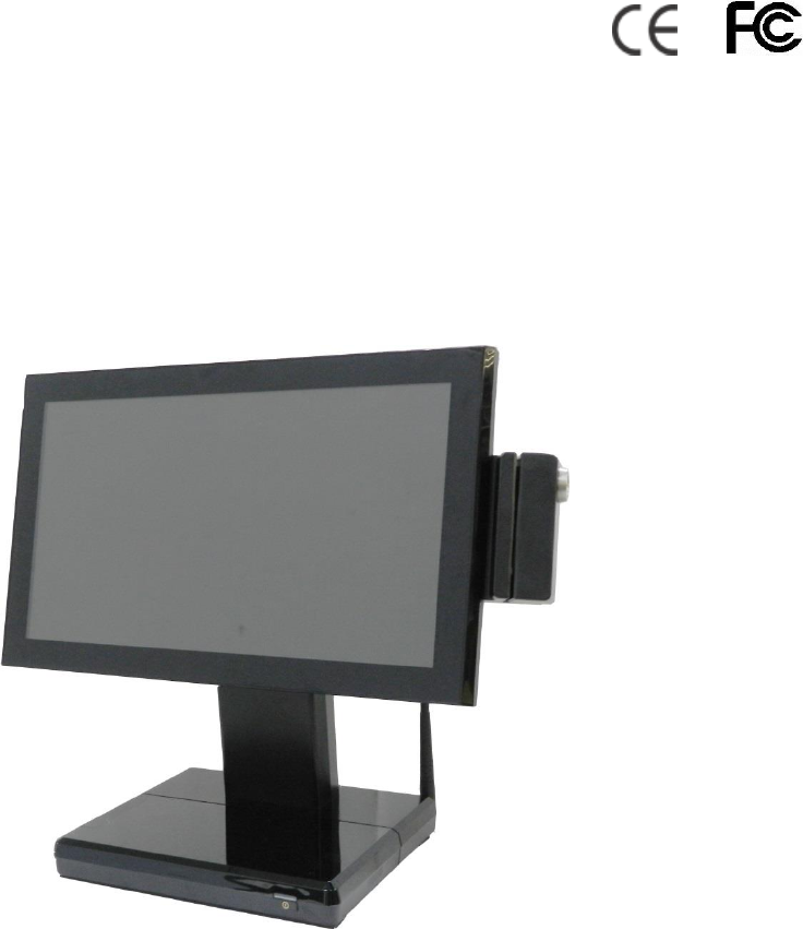
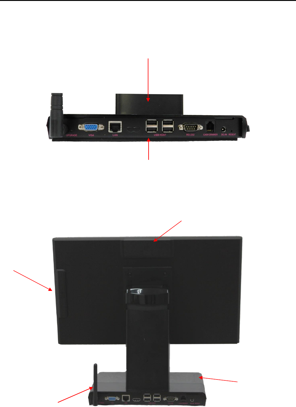
1.2 A Visual Tour of POS AD-1000 Series Terminal
Before you start, take a few moments to become familiar with POS AD-1000 Series Terminal.
Easy to reach I/O Connector Ports
(Back Side of Machine)
Elegant, Solid, Fashionable Compact Design
VFD Mounting Cover
Removable Hard drive
Extraction slot
MSR Mounting
Cover
WiFi
Introduction
3 2014/12/12 Version: 1.0
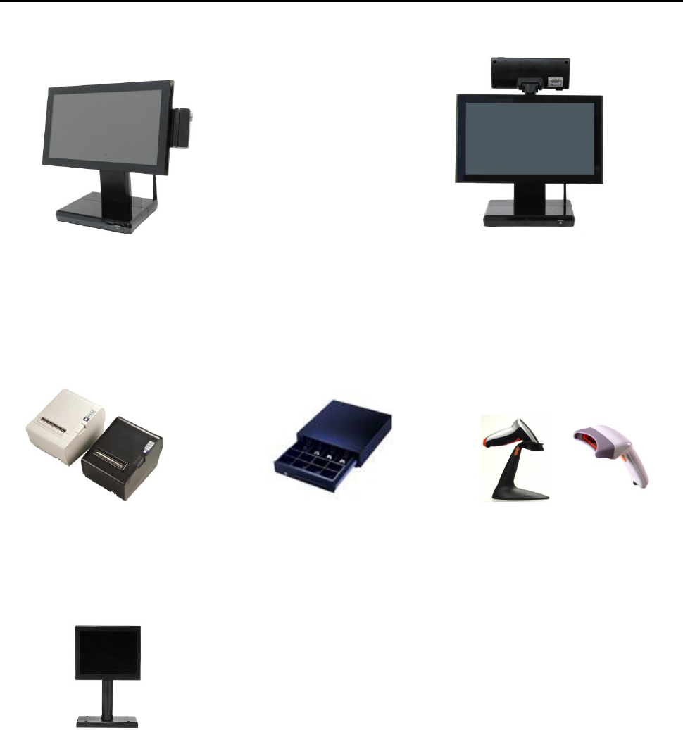
1.2a What Comes With POS AD-1000 Series Terminal
The following items are standard with POS AD-1000 Series terminal.
Before setting up your POS AD-1000 Series terminal, check that the package contains the following
items. If any of the items are missing or damaged, contact your supplier immediately.
Main system with LCD panel
Power adapter + AC power cord
Optional Items:
MSR
VFD Customer Display
2 in 1 Reader (MSR+RFID)
Peripherals (Scanner, Cash drawer, Receipt
printer, 7”, 10” Second LCD monitor)
2 in 1 Reader (MSR+i-Button)
Available in 15” TFT
LCD Touch Monitor
Finger print-Free
Front Bezel Design
Speak Hole
Stand
Power button
Introduction
4 2014/12/12 Version: 1.0
POS AD-1000 with MSR and WiFi
Peripherals
Receipt Printer Cash Register Barcode Scanner
7”,10” second display
VFD Customer Display
Specification
5 2014/12/12 Version: 1.0
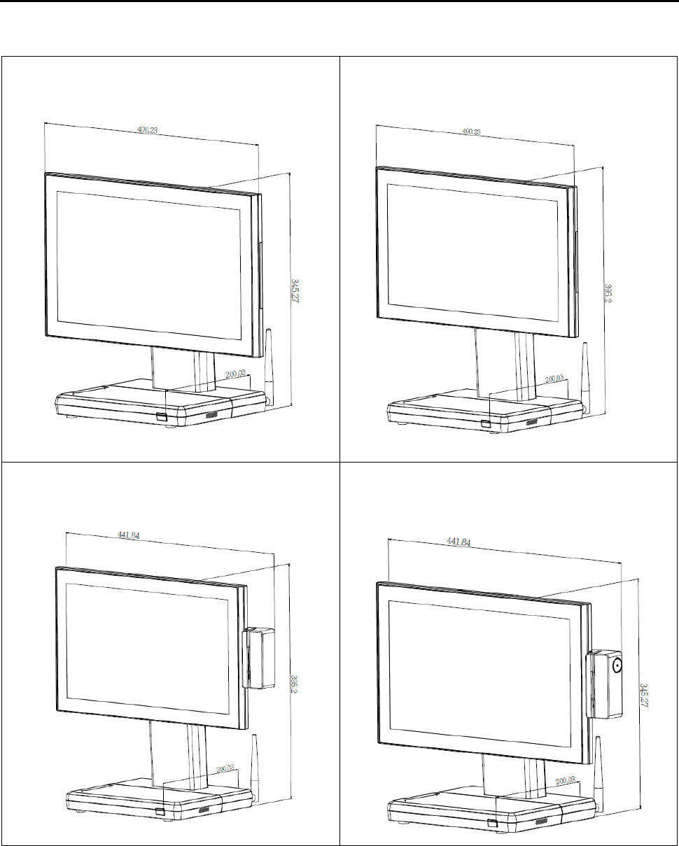
1.2b Dimension 15.6” POS AD-1000
15.6” POS AD-1000 Terminal standard
Dimensions:
15.6” POS AD-1000 Terminal standard
Dimensions:
15.6” POS AD-1000 Terminal
and MSR Dimensions:
15.6” POS AD-1000 Terminal
and 2- in -1 MSR Dimensions:
Specification
6 2014/12/12 Version: 1.0
15.6” POS AD-1000 Terminal
and VFD customer display:
15.6” POS AD-1000 Terminal
and VFD + 2- in -1 MSR Dimensions:
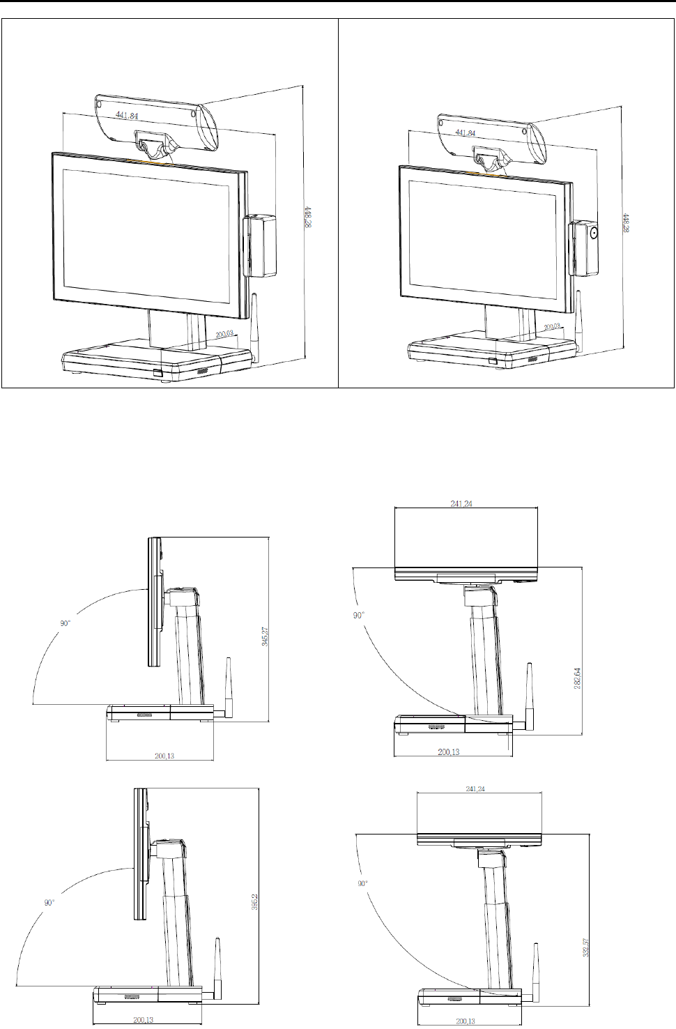
1.2c Adjustable LCD Operation Angle
“Super Firm and Perfectly Secured LCD display Angles from 90 ~ 180 degree.”
Specification
7 2014/12/12 Version: 1.0
1.3 Features
POS AD-1000 Series terminal comes equipped with the following features:
Low power consumption
LV (Low Voltage) design of the device is embedded
with a unique chipset renders power saving function.
Saving cost of ownership
Modular design provides the owner with the
following benefits:
(a) cost effectiveness,
(b) customization flexibility, and
(c) Easy maintenance.
Compact size/Aesthetic design
Slimmest in the POS industry standard [Standard:
400(W) x 200(D) x 345(H) mm, Highest: 400(W) x
200(D) x 395(H) mm]. This elegant, economic POS
system feathers a sleek, compact design base that
saves counter space and adds appeal to the service
environment.
Dust/water proof
AD-1000 features a highly durable, rigorously tested
design that is reliable and dependable in rugged
environments.
Environment protection
Environmental friendly, RoHS compliant product.
High Stability
The AD-1000 has a longer overall system MTBF to
provide a higher stability during operation.
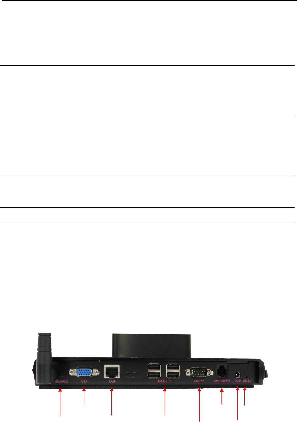
1.4 Connector Panels
The connector panel is located at the bottom of the main unit base. To clearly see the panel you
must open the base cover.
Upgrade
VGA
LAN
USB
RS232
Cash
Drawer
DC-in
Reset

Specification
8 2014/12/12 Version: 1.0
Chart of the connector panel:
I/O Port
Connector Type
Description
Upgrade
Push Button
Use this button to upgrade system.
VGA
VGA Connector
The VGA port is for the external LCD or CRT monitor.
LAN
10/100/1000Mbps
Ethernet
The LAN port is used to hook this device to a local area
network.
USB
USB
The USB (Universal Serial Bus) port can be used to
connect USB devices.
RS232
DSUB Connector
The serial port can be used to connect serial devices such
as printer.
Cash
Drawer
RJ12 Cable
The port is used to hook this device to a cash drawer.
Power
Connector
DC 12V IN power
connector
The power connector mainly supplies power to the
machine. Caution! If the DC 12V power connector is not
connected, the system will not start.
Reset
Push Button
Use this button to reset system.
2. Hardware Setup
Getting Started
This section describes how to install the optional accessories on your POS AD-1000 Touch Terminal
for optimal serviceability.
2.1 Pre-installation Notice
Before you start installing POS AD-1000 terminal, please read the following notices carefully.
1. The POS AD-1000 terminal does support Android system.
2. Do not plug in or unplug any interior devices, such as any function card, when powered on.
3. For installation and compatibility, using the 1G DDR3 RAM from the original manufacturer is
recommended.
4. The spill proof design of POS AD-1000 conforms to IP-65 standard from front bezel.
5. Do not insert or remove any devices or components from the POS AD-1000 terminal while the
power is on.
Hardware Assembly
Please make sure that the system power is turned off and the power supply is disconnected when
making any hardware changes to POS AD-1000 terminal.
Specification
9 2014/12/12 Version: 1.0
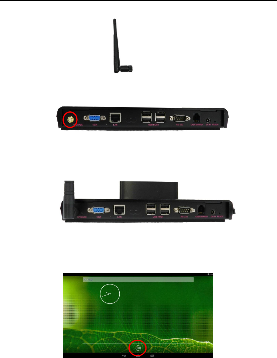
2.2a WiFi Installation
Package Content
A external antenna
Step 1: Please secure external antenna to rear panel of the terminal.
Step 2: Please secure external antenna to rear panel of the terminal.
Step 3: Integration completed..
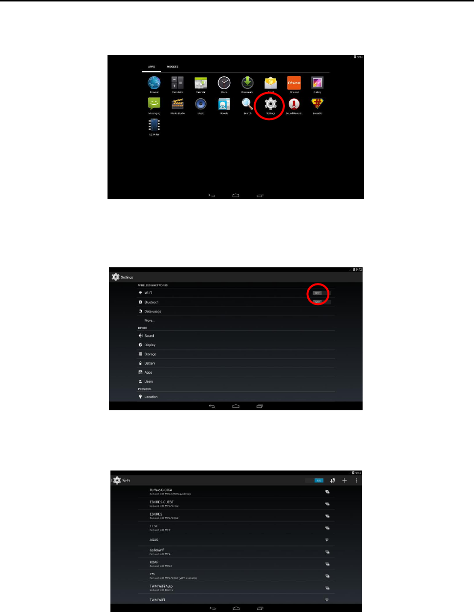
Step 4: Setting WiFi in the system.
Step5: Please press home key in the screen.
Specification
10 2014/12/12 Version: 1.0
Step6: Please press settings icon in the screen.
Step7: Please setting WiFi status from off to on .
Step8: Please select AP as below.
Specification
11 2014/12/12 Version: 1.0
Step9: Please key-in password then press connect button as below.
Step10: WiFi icon will display in the screen.
Step11: WiFi setting completed.
Specification
12 2014/12/12 Version: 1.0
2.2b Motherboard Introduction.
The Power electricity on COM port of AD-1000 is 0 as default. If you want to change power
electricity to +5V or +12V, you have to follow the instruction below.
Prepare nippers to change the position of the jumpers from Ring-IN to +5V or +12V as the picture
shown below.
LVDS
Power
RFID
SATA
VFD
MSR
R or C Touch
VGA
LAN
port
USB
COM
DC in
Cash
Drawer
Upgrade
Reset
Micro SD
card slot
Speaker
connector
Specification
13 2014/12/12 Version: 1.0
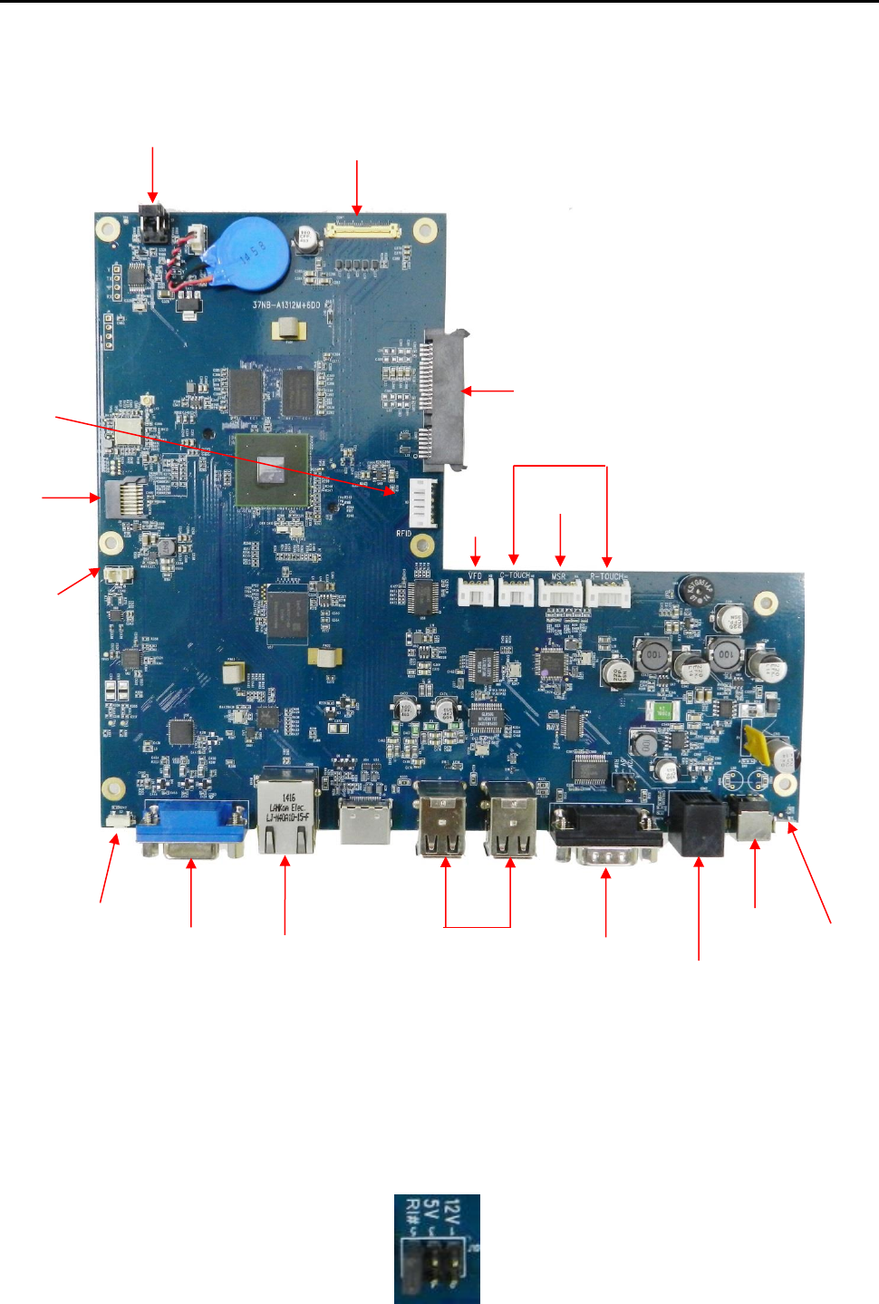
2.2c Micro SD card Installation.
Package Content
A micro SD card
Installing a Micro SD card
1. Please turn off the system power.
2. Turn over the AD-1000, the Micro SD Card socket is found under the case.
3. Unscrew the metal piece.
4. Plug-in the Micro SD Card as below.
5. Replace the metal piece and retighten the screw.
Specification
14 2014/12/12 Version: 1.0
6. You may turn the system back on once the Micro SD card is completely installed.
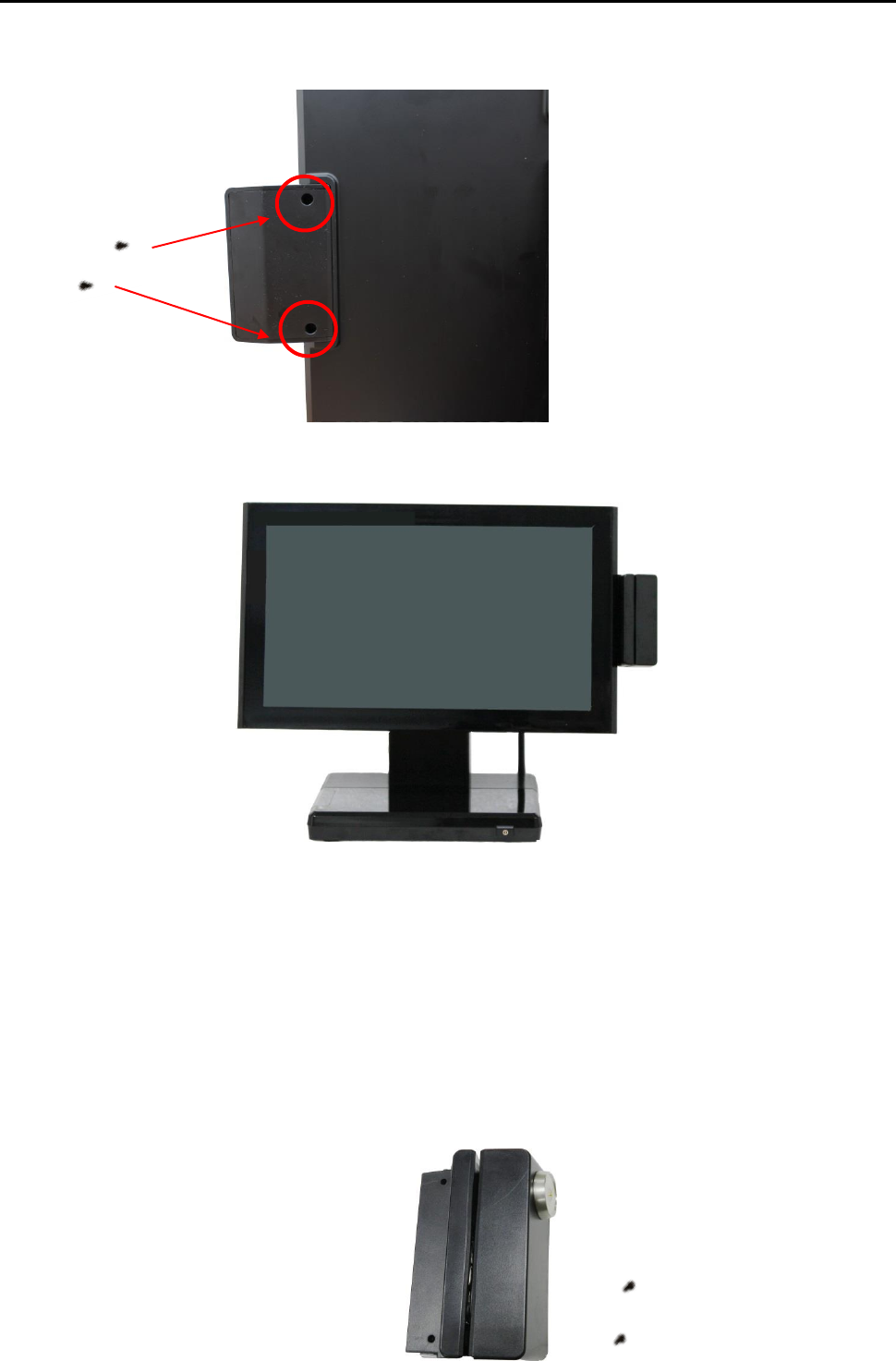
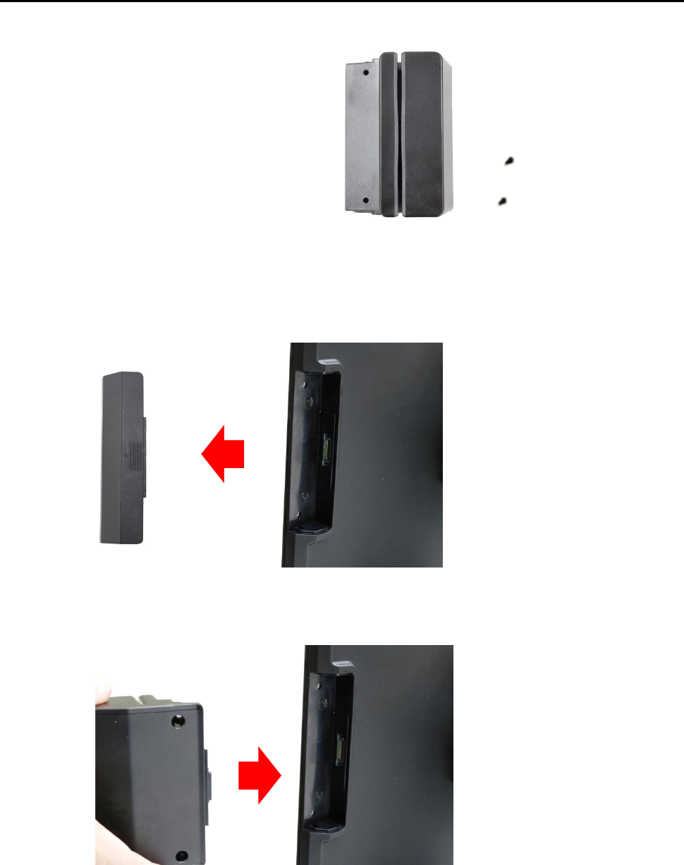
2.2d Magnetic Stripe Reader Installation.
An optional Magnetic Stripe Reader (MSR) can be installed on the right side of AD-1000 Terminal.
Package Content
An MSR housing
Screw x 2
Installing an MSR
Step 1: Please turn off the system power.
Step 2: Please remove the side cover of the terminal.
Step 3: Please push in MSR housing into the terminal.
Specification
15 2014/12/12 Version: 1.0
Step 4: Using two screws to secure MSR housing to the right side of the monitor.
Step 5: Integration completed.
Step 6: You may turn the system back on once the MSR is completely installed.
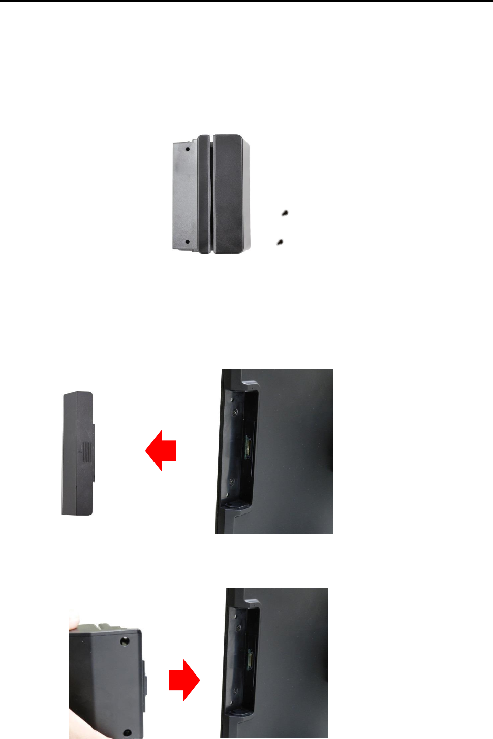
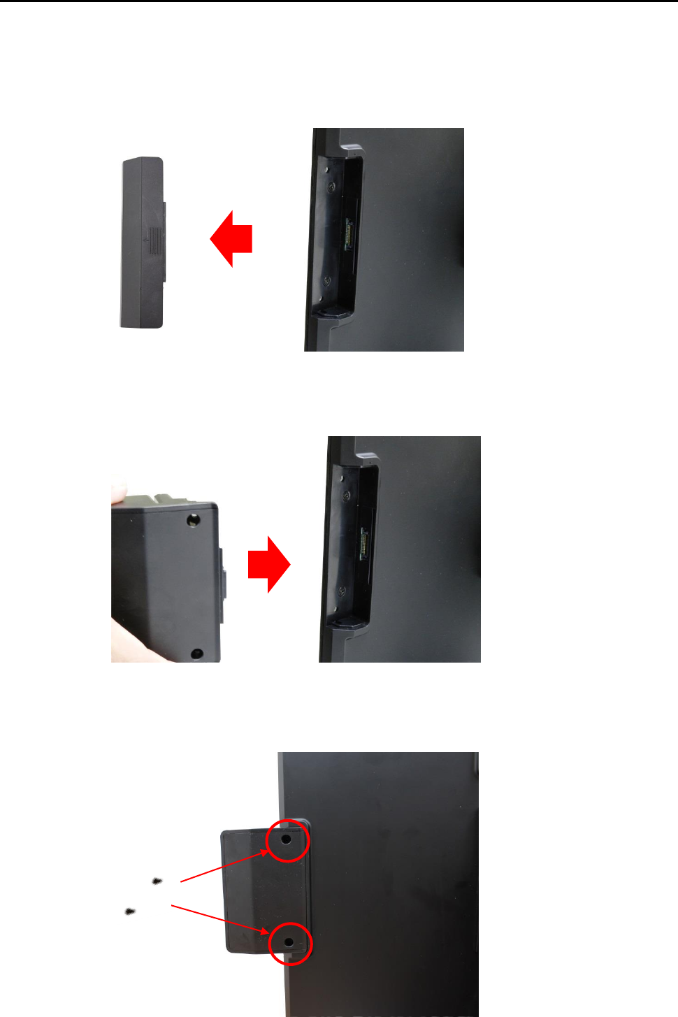
2.2e 2-in-1 Card Reader Installation.
An optional 2-in-1/ 3-in-1Card Reader can be installed on the right side of AD-1000 Terminal.
Package Content
A 2-in-1 Card Reader housing
Screw x 2
Specification
16 2014/12/12 Version: 1.0
Installing a 2-in-1 Card Reader
Step 1: Please turn off the system power.
Step 2: Please remove the side cover of the terminal.
Step 3: Please push in 2-in-1 MSR housing into the terminal.
Step 4: Using two screws to secure 2-in-1 MSR housing into the right side of the monitor.
Specification
17 2014/12/12 Version: 1.0
Step 5: Integration completed.
Step 6: You may turn the system back on once the 2-in-1 MSR is completely installed.
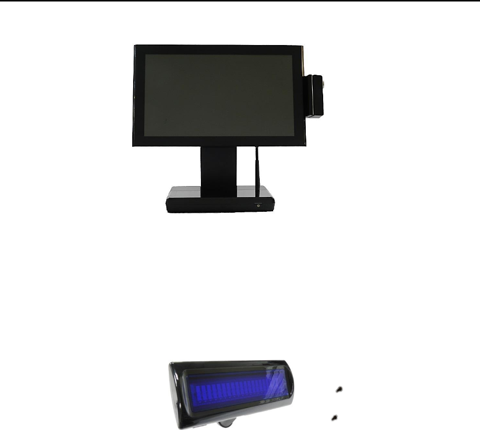
2.2f VFD Customer Display Installation.
Package Content
A VFD
Screw x 2
Installing a VFD
Step 1: Please turn off the system power.
Step 2: Please remove the side cover of the terminal.
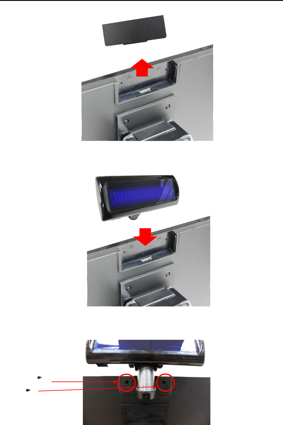
Specification
18 2014/12/12 Version: 1.0
Step 3: Please push in VFD customer display to the terminal.
Step 4: Using two screws to secure VFD customer display to the up side of the monitor.
Specification
19 2014/12/12 Version: 1.0
Step 5: Integration completed.
Step 6: Turn on VFD customer display power switch, and then turn on system power.
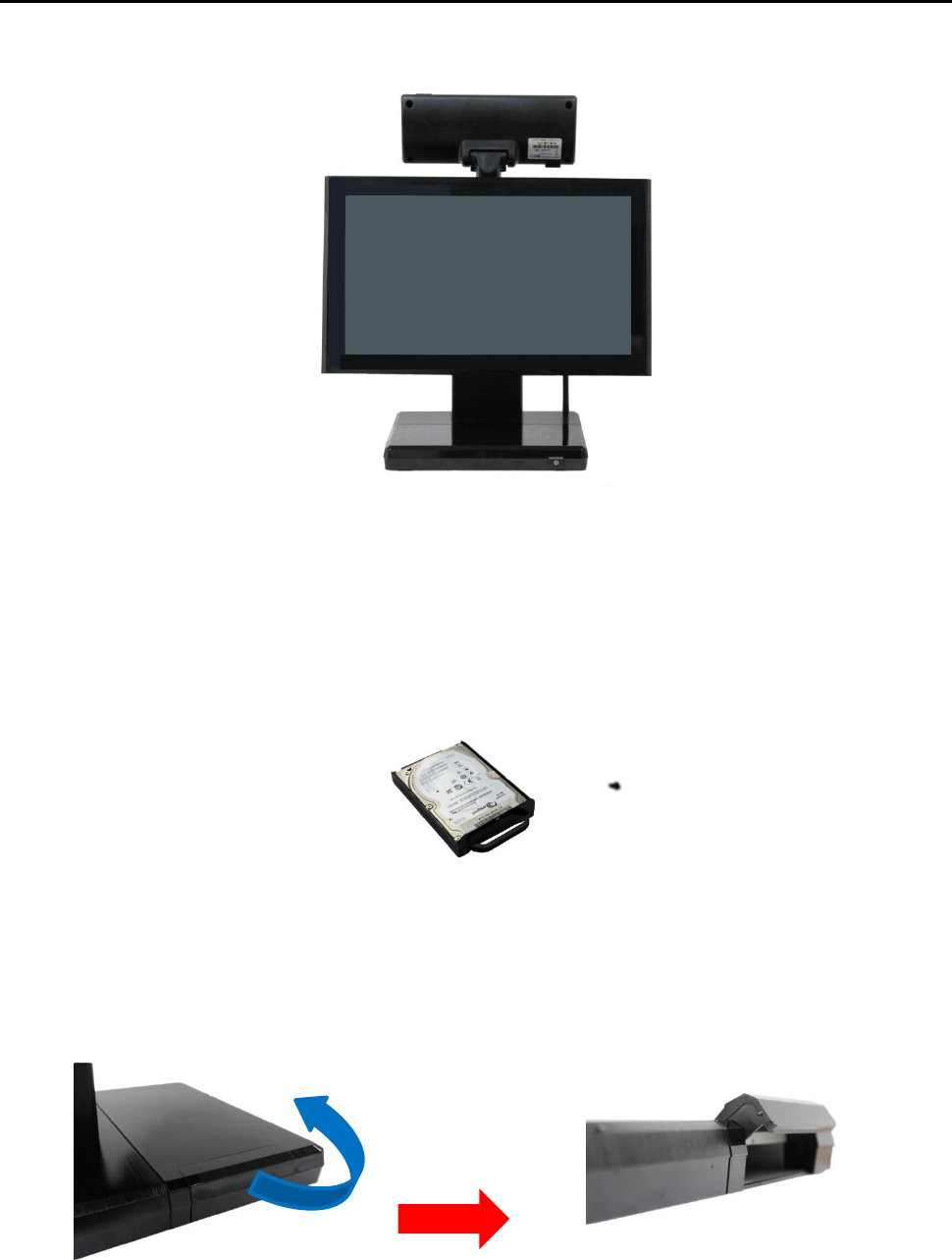
2.2g HDD/SSD kit Installation.
Package Content
A 2.5” HDD/SSD kit
Screw x 1
Installing a 2.5” HDD/SSD kit
Step 1: Please turn off the system power.
Step 2: Please open the HDD cover.
Step 3: Please push in HDD or SSD kit into the terminal where indicated below.
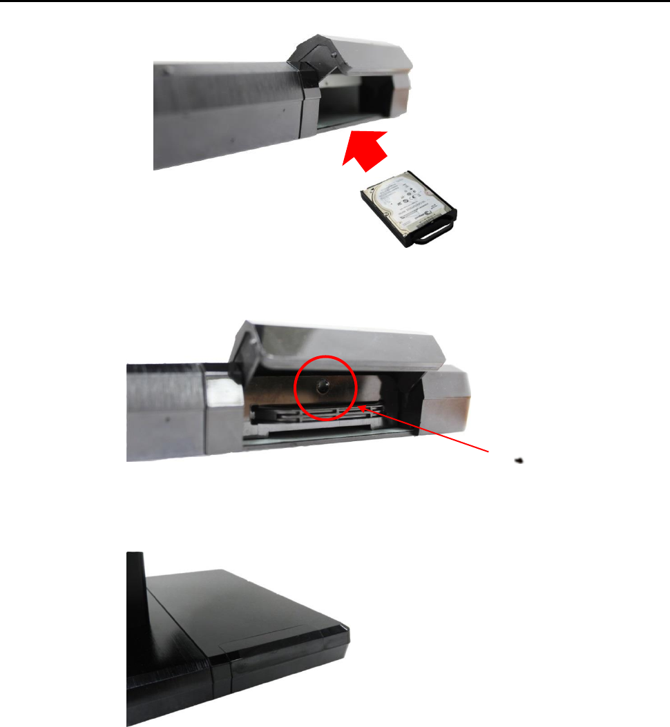
Specification
20 2014/12/12 Version: 1.0
Step 4: Please screw a screw indicated below to fix HDD or SSD kit.
Step 5: Close the HDD cover to complete the installation.
Step 6: Integration completed.
2.2h RFID Installation
An optional RFID Card can be installed on the AD-1000 Terminal.
Specification
21 2014/12/12 Version: 1.0
Package Content
A RFID kit
Screw x 2
Installing a RFID kit
Step 1: Please turn off the system power.
Step 2: Please remove the side cover of the terminal.
Step 3: Please push in RFID kit into the terminal.
Step 4: Using two screws to secure RFID kit to the right side of the monitor.
Specification
22 2014/12/12 Version: 1.0
Step 5: Integration completed.
Step 6: You may turn the system back on once the RFID kit is completely installed.
3. Service manual
3.1 Touch/LCD Panel
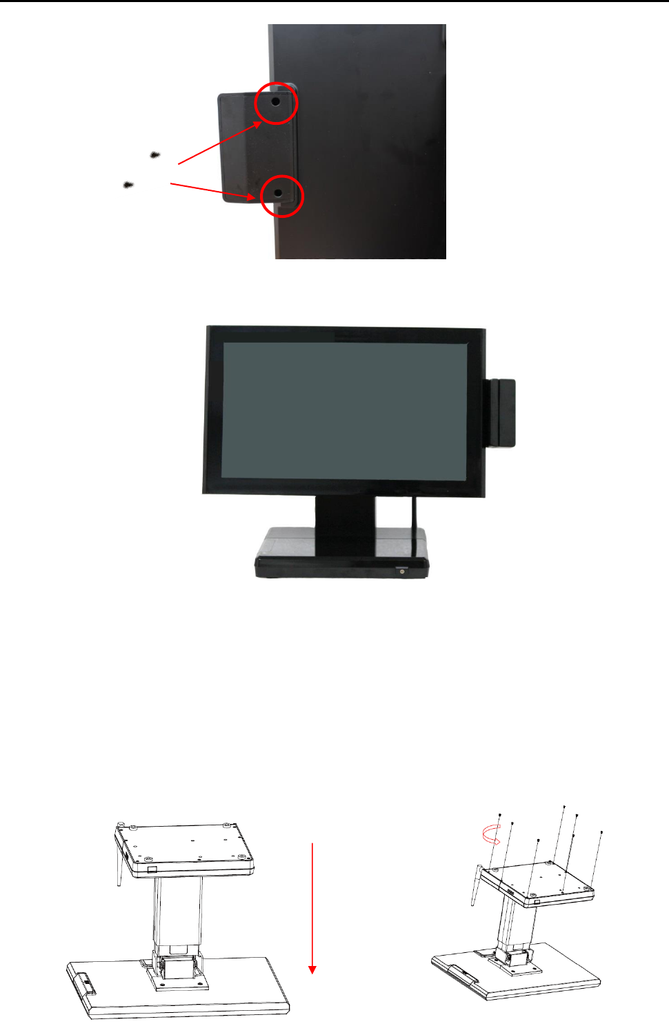
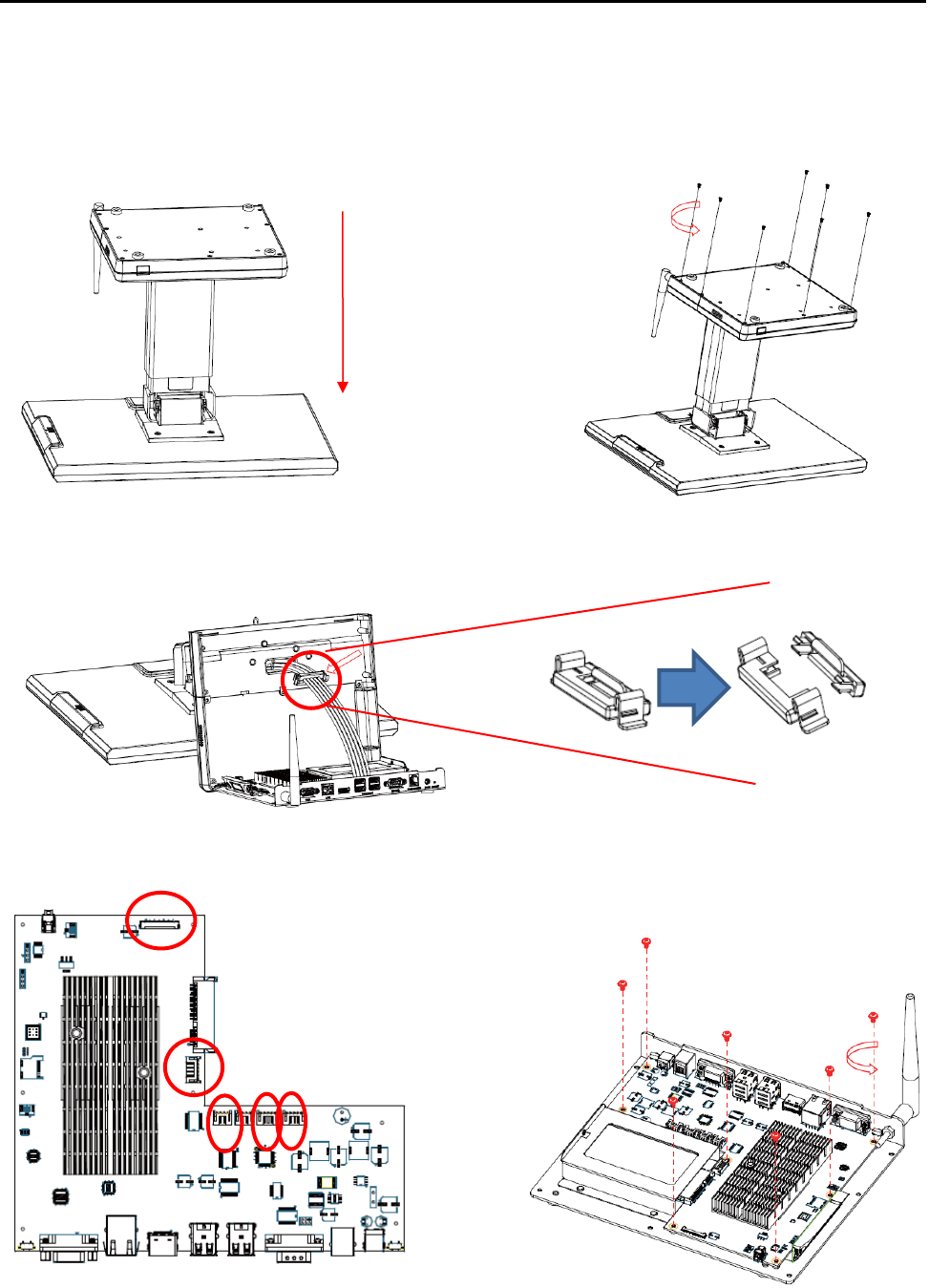
Step 1: Please position the terminal as shown below Step 2: Unscrew the metal piece.
on a working table with “soft protective pad”.
Specification
23 2014/12/12 Version: 1.0
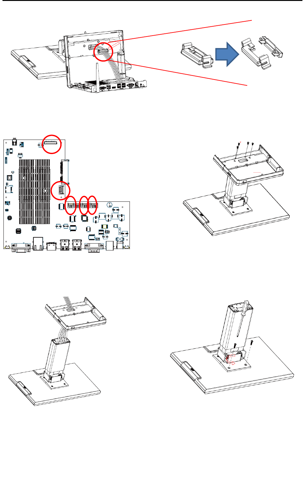
Step 3:Please open the Wire Clip.
Step 4: Please remove 5 cables of the Step5: Please remove 4 screws of the stand.
motherboard.
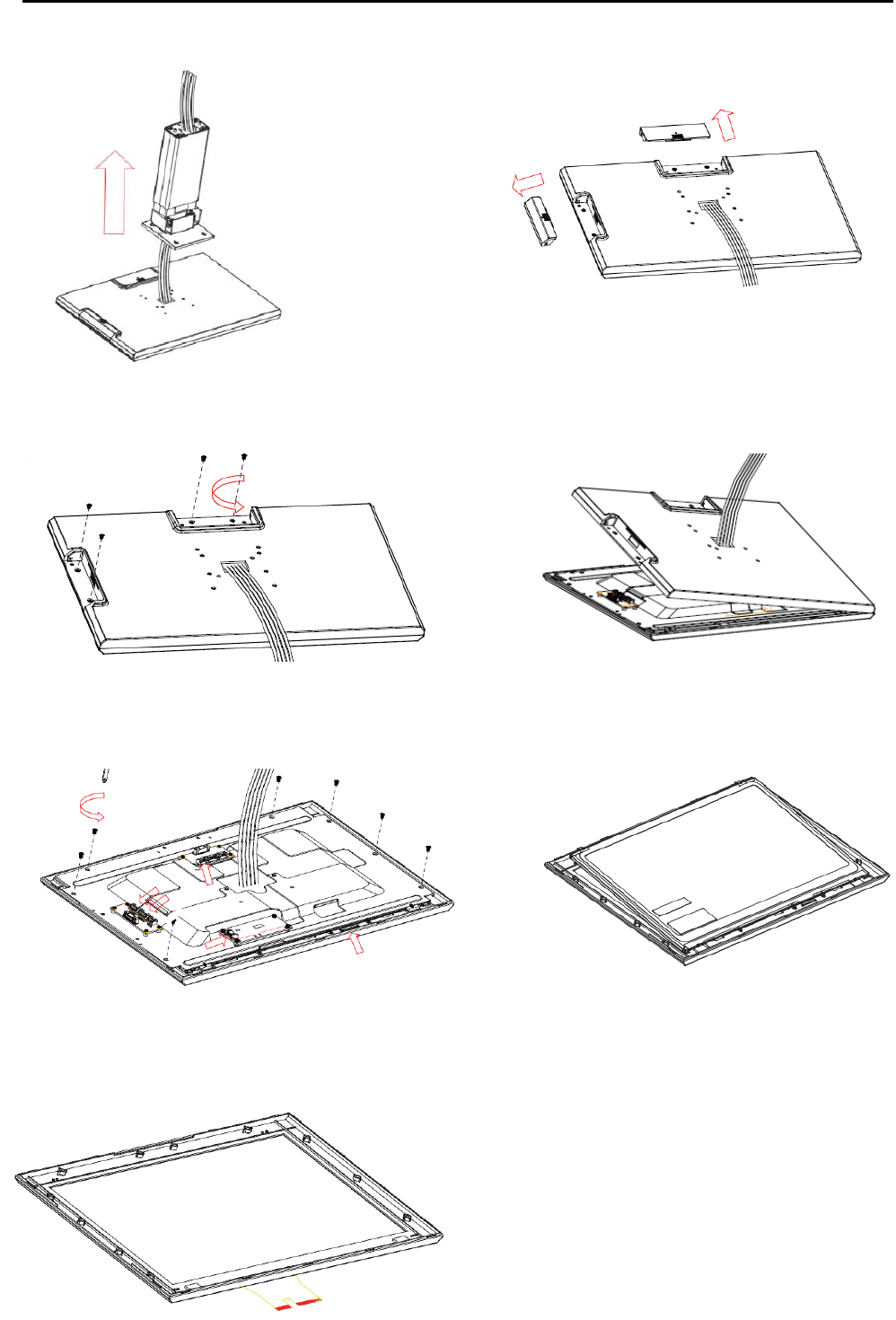
Step 6: Please remove the stand. Step7: Please remove 4 screws of the hinge.
h
Specification
24 2014/12/12 Version: 1.0
Step 8: Please remove the hinge. Step 9: Please remove side cover of the
monitor.
Step 10: Please remove 4 screws. Step 11: Please remove back cover.
Step 12: Please remove 7 screws of the LED bracket. Step 13: Please remove LED panel.
Step 14: Remove completed. Step 15: After touch panel or LED panel is
replaced, please reverse the step 1-13 to
assemble the machine.
Specification
25 2014/12/12 Version: 1.0
3.2 Motherboard
Step 1: Please position the terminal as shown below Step 2: Unscrew the metal piece.
on a working table with “soft protective pad”.
Step 3: Please open the Wire Clip.
Step 4: Please remove 5 cables of the M/B. Step5: Please remove 7 screws from M/B
to separate and replace motherboard.
.Step 6: Please reverse step 1-5 to assemble the machine.
h

Specification
26 2014/12/12 Version: 1.0
4. Specifications
AD1000 System Specifications
Outlook
Dimension
400(L)x300(D)x345(H) mm
Weight
4.7kg
Color
Black
Hardware Specification
CPU
FSL i.MX6Q 1GHz, Quad Cortex A9
System Memory
1GB LVDDR3 800MT/s
Graphics
3D GPU (Vivante GC2000) and Vector Graphics GPU
Display
Size
15.6" LED panel
Resolution
1366x768;wide screen
Touch Screen
15.6" 5-wired resistive touch or projected capacitive touch
Bezel free
Yes
Storage
EMMC 8G flash menory
WiFi
802.11 b/g/n
Speaker
Internal speaker 2W x 1
Power Supply
60W (12V/5A )power adapter
External I/O Ports
USB 2.0
4
Serial
1
LAN
10/100/1000Mbps
Cash Drawer
1 x RJ-11 (12V/24V)
VGA
1 ; Second display with external power adapter
Optional Peripherals
MSR
3 Tracks , JIS-I or II , USB interface
VFD
2 x 20 VFD Customer Display , RS232 interface
Second Display
Support 7"/10" second display
RFID
RFID 13.56MHZ , RS232 interface
2-in-1 Reader (MSR+i-Button)
Yes

Specification
27 2014/12/12 Version: 1.0
2-in-1 Reader (MSR+RFID)
Yes
Optional Storage
2.5" HDD/SSD,micro SD card
Barcode Scanner
USB interface
Thermal Printer
RS232 interface
Control Buttons
Power
1 (ON /OFF;include LED display)
Reset
1
Upgrade
1
Environment
Green Product
RoHS,REACH
EMI/Safety
CE CLASS A,FCC Part 15 Subpart B,CLASS A
Operating Temperature
0°C ~ 40°C (32°F ~ 104°F)
Storage Temperature
-10°C ~ 55°C (14°F ~131°F)
Relative Humidity
10% ~ 90% (Non-Condensing)
Software Specification
OS
Android 4.4.2