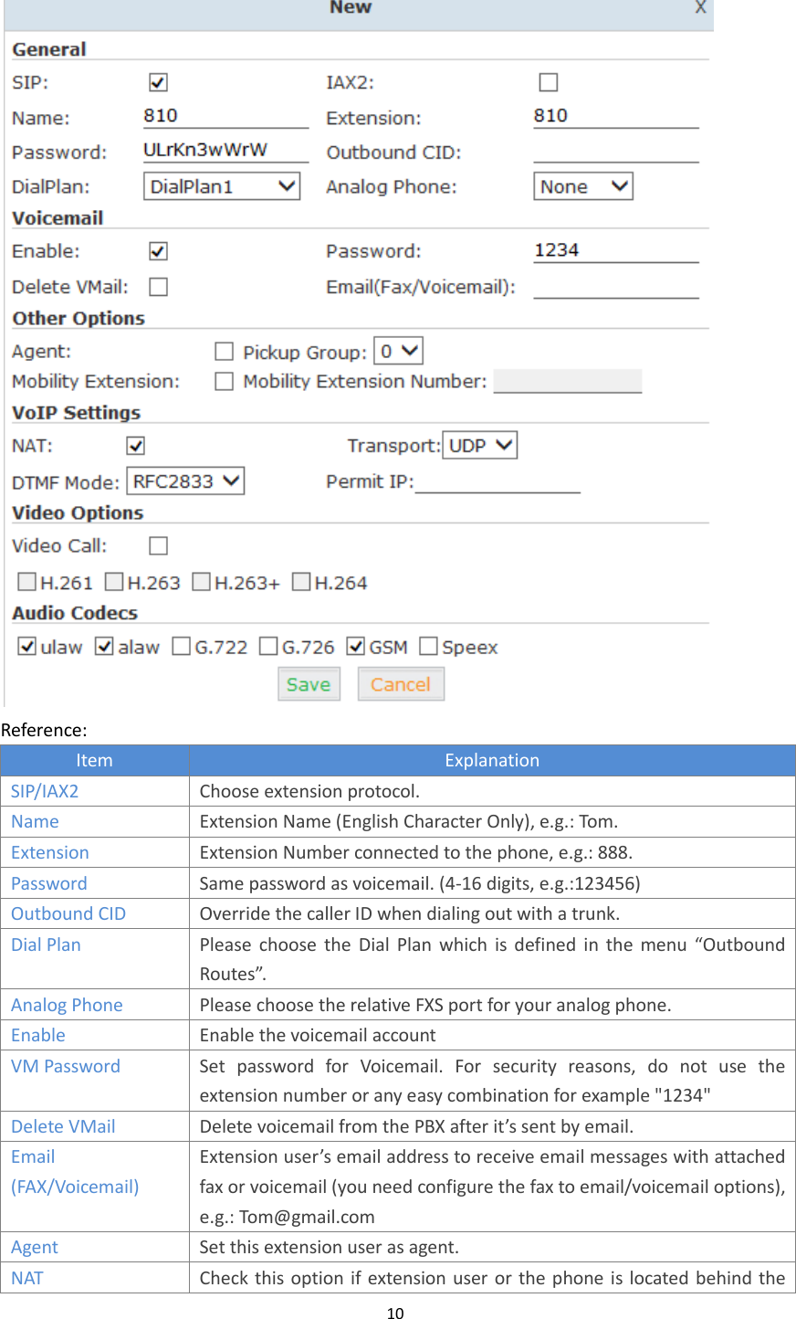
ZYCOO UC510 IP Office for SOHO User Manual
ZYCOO Co., LTD. IP Office for SOHO Users Manual
UserManual.wiki
>
ZYCOO
>
UC510 User Manual
Users Manual
Navigation menu
Upload a User Manual
Namespaces
Wiki Guide
HTML
PDF
Info
Views
User Manual
Discussion / Help
Navigation

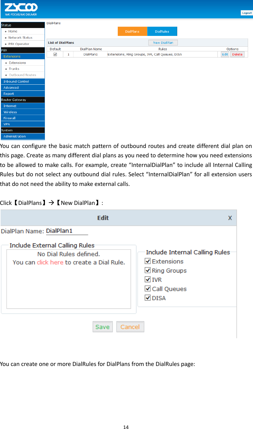
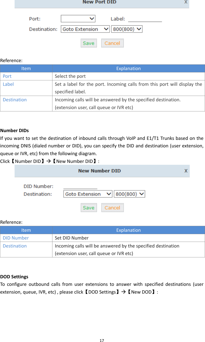
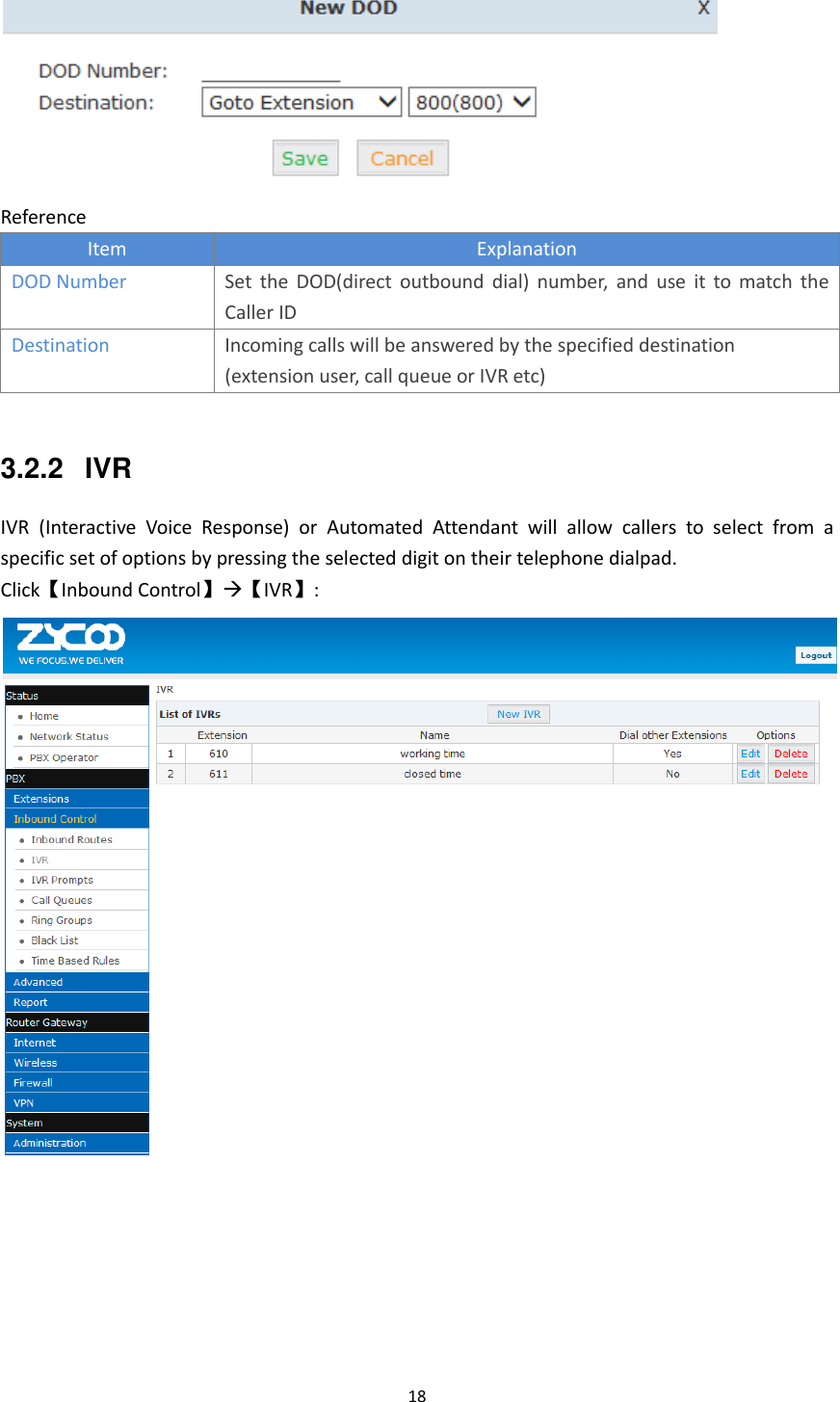
![15 Click【DialRules】【New DialRule】to create a new Dial Rule Reference: Item Explanation Rule Name Define the name for the dial rule. PIN Set Input this PIN when you use this dial rule. Place this call through Select one of the trunk groups that have been set up to use for this dial rule Custom Pattern N any digit from 2 to 9 Z any digit from 1 to 9 X any digit from 0 to 9 . One or more digits Delete[ ]digits prefix Define how many digits will be deleted from the dialed number.](https://usermanual.wiki/ZYCOO/UC510/User-Guide-2489555-Page-17.png)
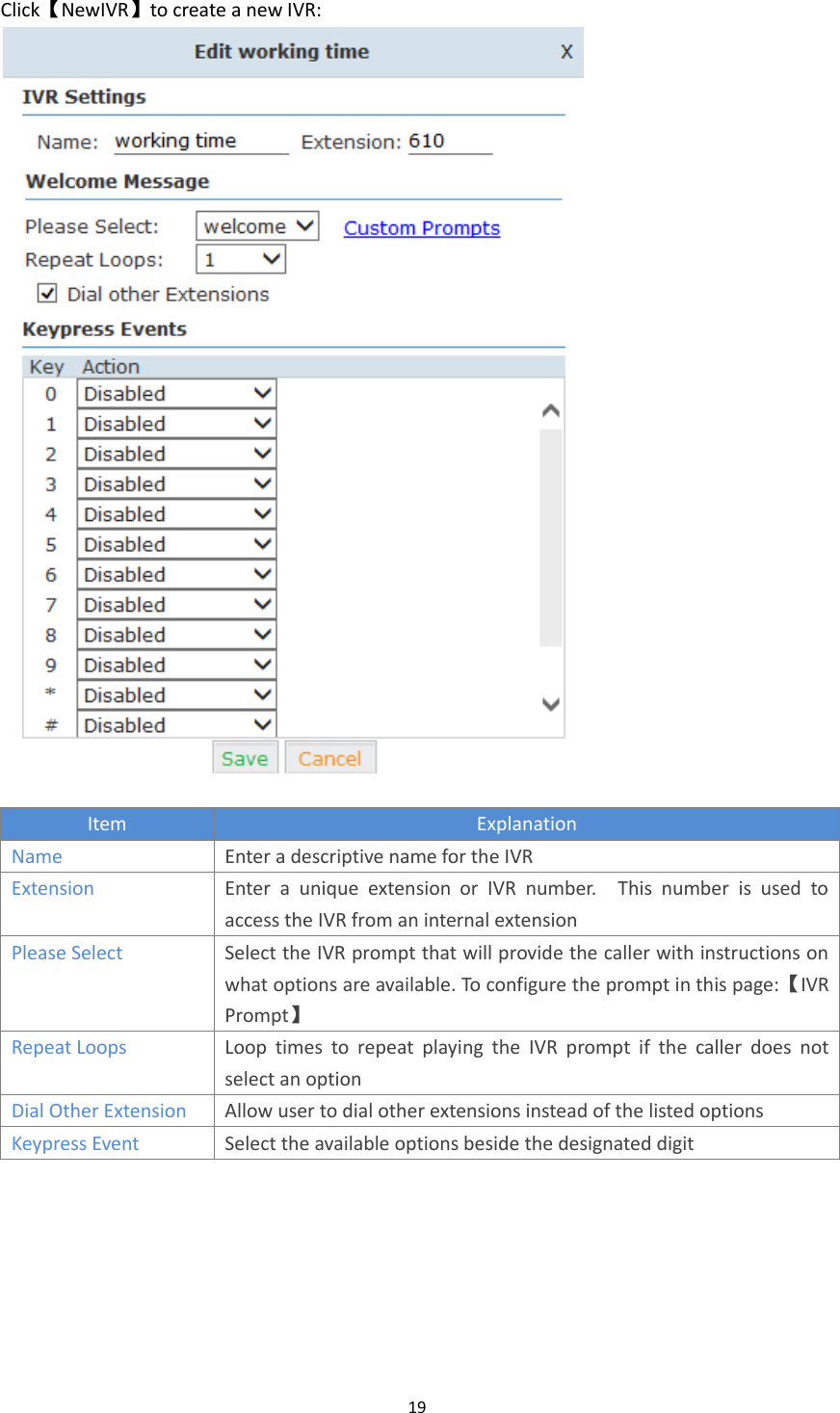
![16 For example, user dialed 94166445775 and you selected to delete 1 digit, then 4166445775 is sent out to the trunk. Auto-add digit[ ] If add digit “9”, when dial 12345, 912345 will be sent. 3.2 Inbound Control 3.2.1 Inbound Routes Click【Inbound Control】【Inbound Routes】 General Distinctive Ring Tone:mapping the custom ring tone file, e.g.: Set distinctive ring tone as “External”, the phone will play this ring tone when receiving the call. Note: The phone must support such feature as well. Select all calls coming in on a specific port (FXO/VoIP) and select which destination (Extension User, IVR, Queue, Conference Bridge, IVR, etc) should answer those calls. Setting the label will assign this label to be displayed. Port DIDs To have incoming calls from a PSTN trunk port (FXO trunk) answered by a specific extension user, call queue, conference bridge, or IVR, please configure here: Click【Port DIDs】【New Port DIDs】:](https://usermanual.wiki/ZYCOO/UC510/User-Guide-2489555-Page-18.png)