Users Manual

FCC Caution:
Any Changes or modifications not expressly approved by the party responsible for compliance
could void the user's authority to operate the equipment.
This device complies with part 15 of the FCC Rules. Operation is subject to the following
two conditions: (1) This device may not cause harmful interference, and (2) this device
must accept any interference received, including interference that may cause undesired
operation.
IMPORTANT NOTE:
FCC Radiation Exposure Statement:
This equipment complies with FCC radiation exposure limits set forth for an
uncontrolled environment .This equipment should be installed and operated with
minimum distance 20cm between the radiator& your body.
This transmitter must not be co-located or operating in conjunction with any other antenna or
transmitter.
Note: This equipment has been tested and found to comply with the limits for a Class B digital
device, pursuant to part 15 of the FCC Rules. These limits are designed to provide
reasonable protection against harmful interference in a residential installation. This
equipment generates, uses and can radiate radio frequency energy and, if not installed and
used in accordance with the instructions, may cause harmful interference to radio
communications. However, there is no guarantee that interference will not occur in a
particular installation. If this equipment does cause harmful interference to radio or television
reception, which can be determined by turning the equipment off and on, the user is
encouraged to try to correct the interference by one or more of the following measures:
—Reorient or relocate the receiving antenna.
—Increase the separation between the equipment and receiver.
—Connect the equipment into an outlet on a circuit different from that to which the receiver is
connected.
—Consult the dealer or an experienced radio/TV technician for help.
1
Table of Contents
Safety Notice
Please read the following safety notices before installing or using this device. They are crucial
for safe and reliable operation of the device. Failure to follow the instructions contained in this
document may result in damage to your device and void the manufacturer’s warranty.
1. Please use the external power supply which is included in the package. Other power
supplies may cause damage to the device, affect the performance or induce noise.
2. Before using the external power supply in the package, please check your building power
voltage. Connecting to Inaccurate power voltage may cause fire and damage.
3. Please do not damage the power cord. If the power cord or plug is impaired, do not use it.
Connecting a damaged power cord may cause fire or electric shock.
4. Ensure the plug-socket combination is accessible even after the device is installed. In
order to service this device it will need to be disconnected from the power source.
5. Do not drop, knock or shake the device. Rough handling can break internal circuit boards.
6. Do not install the device in places where there is direct sunlight. Also do not place the
device on carpets or cushions. Doing so may cause the device to malfunction or cause a fire.
7. Avoid exposing the device to high temperature (above 40°C), low temperature (below
-10°C) or high humidity. Doing so could cause damage and will void the manufacturer
warranty.
8. Keep this device far away from water or any liquid which would damage the device.
9. Do not attempt to open it. Non-expert handling to the device could cause damage and will
immediately void the manufacturer warranty.
10. Consult your authorized dealer for assistance with any issues or questions you may have.
11. Do not use harsh chemicals, cleaning solvents, or strong detergents to clean the device.
12. Wipe it with soft cloth that has been slightly dampened in a mild soap and water solution.
13. If you suspect your device has been struck by lightning, do not touch the device, power
plug or phone line. Call your authorized dealer for assistance to avoid the possibility of
electric shock.
14. Ensure the device is installed in a well ventilated room to avoid overheating and
damaging the device.
15. Before you work on any equipment, be aware of any hazards involved with electrical
circuitry and be familiar with standard practices for preventing accidents. If you are in a
situation that could cause bodily injury.
2
Directory
Safety Notice ..................................................................................................................................... 1
Chapter 1 Brief Introduction .......................................................................................................... 4
1.1 Brief Introduction of UC510/UC520 ....................................................................... 4
1.2 Main Features ....................................................................................................... 4
1.3 Hardware Interfaces .............................................................................................. 5
1.4 Environmental Requirements ................................................................................ 6
1.5 Packing List ............................................................................................................ 6
Chapter 2 Getting Started .............................................................................................................. 7
2.1 Home ................................................................................................................. 7
2.2 Network Status .................................................................................................. 7
2.3 PBX Operator ..................................................................................................... 8
Chapter 3 PBX ................................................................................................................................ 9
3.1 Extensions ......................................................................................................... 9
3.1.1 Extensions ......................................................................................................... 9
3.1.2 Trunk ................................................................................................................ 11
3.1.3 Outbound Routes ............................................................................................ 13
3.2 Inbound Control .............................................................................................. 16
3.2.1 Inbound Routes ............................................................................................... 16
3.2.2 IVR ................................................................................................................... 18
3.2.3 IVR Prompts ..................................................................................................... 20
3.2.4 Call Queue ....................................................................................................... 22
3.2.5 Ring Groups ..................................................................................................... 25
3.2.6 Blacklist ........................................................................................................... 26
3.2.7 Time Based Rules ............................................................................................ 27
3.3 Advanced ......................................................................................................... 29
3.3.1 Options ............................................................................................................ 29
3.3.2 Voicemail ......................................................................................................... 31
3.3.3 SMTP Settings .................................................................................................. 32
3.3.4 Music Settings ................................................................................................. 33
3.3.5 DISA ................................................................................................................. 34
3.3.6 Follow Me ........................................................................................................ 35
3.3.7 PIN Sets ........................................................................................................... 36
3.3.8 Speed Dial ........................................................................................................ 37
3.3.9 Smart DID ........................................................................................................ 37
3.3.10 Callback ........................................................................................................... 38
3.3.11 Phone Book ..................................................................................................... 39
3.3.12 Feature Codes.................................................................................................. 39
3.3.13 IP Phone Provisioning ...................................................................................... 41
3.3.14 Set Voice Prompt Language ............................................................................. 43
3.4 Report .............................................................................................................. 43
3.4.1 Register Status ................................................................................................. 43
3.4.2 Call Logs ........................................................................................................... 44
3.4.3 PBX Debug Logs ............................................................................................... 44
3
Chapter 4 Router Gateway ....................................................................................................... 45
4.1 Internet ................................................................................................................. 45
4.1.1 WAN ................................................................................................................ 45
4.1.2 LAN .................................................................................................................. 48
4.1.3 Static Routing .................................................................................................. 51
4.1.4 QoS .................................................................................................................. 52
4.1.5 IPv6 Setup ........................................................................................................ 56
4.1.6 DHCP Client Info .............................................................................................. 56
4.2 Wireless ................................................................................................................. 57
4.2.1 Basic ................................................................................................................ 57
4.2.2 Advanced ......................................................................................................... 59
4.2.3 Security ............................................................................................................ 61
4.2.4 Statistics .......................................................................................................... 64
4.3 Firewall .................................................................................................................. 67
4.3.1 IP/Port Filter .................................................................................................... 67
4.3.2 System Firewall ................................................................................................ 68
4.3.3 Port Forward.................................................................................................... 69
4.3.4 Virtual Server ................................................................................................... 70
4.3.5 DMZ ................................................................................................................. 71
4.4 VPN ........................................................................................................................ 72
4.4.1 VPN Server ...................................................................................................... 72
Chapter 5 System ..................................................................................................................... 75
5.1 Administration ....................................................................................................... 75
5.1.1 Management ................................................................................................... 75
5.1.2 Activate Configuration ..................................................................................... 76
5.1.3 Reset & Reboot................................................................................................ 76
5.1.4 Statistics .......................................................................................................... 77
5.1.5 Upgrade ........................................................................................................... 77
5.1.6 Backup & Restore ............................................................................................ 78
5.1.7 Troubleshooting .............................................................................................. 79

4
Chapter 1 Breif Introduction
1.1 Brief Introduction of UC510/UC520
UC510/520 is designed specifically as an IP Office for SOHOs (Small Office and Home Offices). The
new solution offers not only a Wi-Fi router supporting VPN Client/Server, VLAN, and external
ADSL connection... but also a fully featured IP PBX that can host up to 10 extensions with 2
analog ports connected, and supports Call Forward, Call Recording, Blind/Attendant Transfer,
and many other features.
UC510/520 is configured and managed through a single web GUI which significantly reduces the
time and effort required to install the product. This simplified management and reduction in
hardware costs through merging two products into one makes the UC510 an amazing and cost
effective solution for SOHOs.
Telephony Module: Built-in 2 FXO or 1FXOS; LTE is default in UC520.
Model FXS FXO LTE
UC510 1 1 0
0 2 0
UC520 1 1 1
0 2 1
1.2 Main Features
PBX Features
BLF
Blind/Attended Transfer
Call Forward
Call Pickup
DID
DISA
Dial Plan
Follow Me
IVR/ IVR Prompts
Inbound Route
Music On Hold
Outbound Route
Phone Provisioning
Ring Group
SIP/FXO Trunk
Time Rule
Voicemail/Voicemail to Email
Router Features
Internet Access (PPPoE, Static or DHCP)
VLAN (IEEE802.1Q)
DHCP List
Blind IP to MAC
Wi-Fi Basic Setup
Wi-Fi Security Setup
Wi-Fi Mac Address Filter
Wi-Fi Advanced Setup
Online Host
NAT: Port Forwarding/DMZ Host
5
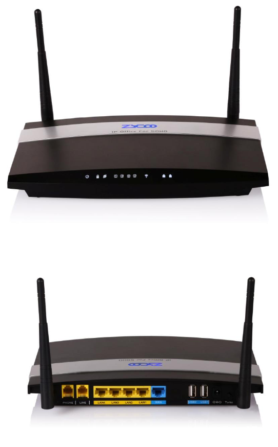
1.3 Hardware Interfaces
UC510 Front Panel
UC510Rear Panel
1 * Turbo Button
1 * Power Interface (DC 12V 2A)
5 * Ethernet Interfaces (10/100Mbps)
2 * Analog Ports(FXO/FXS)
2* USB Ports
6
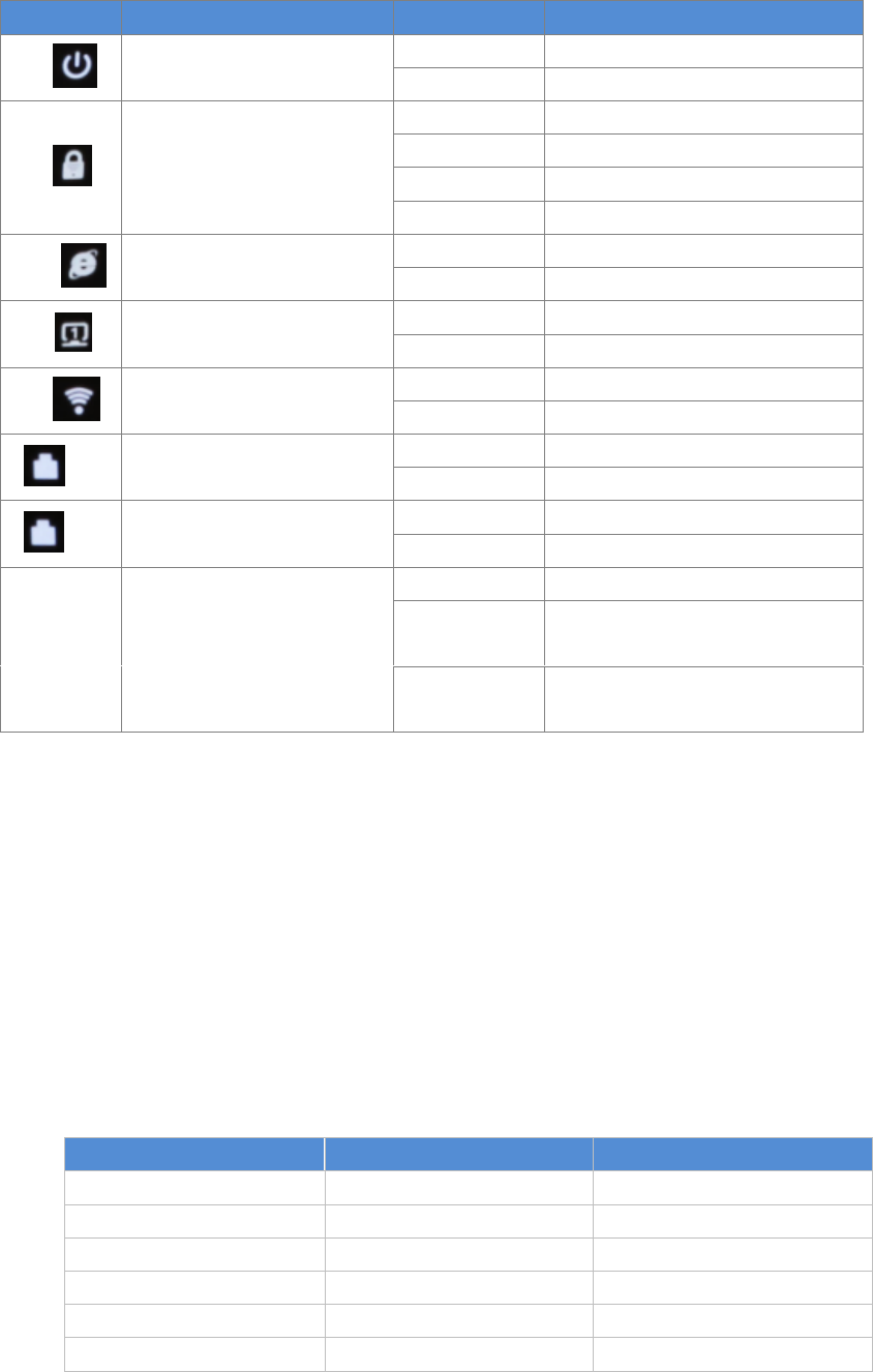
UC510/520 LED Indication:
Indication
Function
Status
Explanation
PWR
Power Status
On
Power On
Off
Power Off
WPS
WPS Status
On
WSC Succeeded(Off after300s )
Off
WPS Ready or Disabled
200ms Blink
WSC Running, Timeout 120s
100ms Blink
WSC Failed or Timeout 120s
WAN
WAN Data Status
Blink
Data Transporting
Off
Line Disconnected
LAN
LAN(1..2..3..4) Data Status
Blink
Data Transport
Off
Line Disconnected
Wi-Fi
Wireless Status
On
Wi-Fi Enabled
Off
Wi-Fi Disabled
1
FXO
On
Channel Loading Succeeded
Off
Channel Loading Failed
2
FXS
On
Channel Loading Succeeded
Off
Channel Loading Failed
*3G/4G
3G/4G Status
(UC520 support)
On
Module Works
Blink
Module Loading Succeeded or
Data Transporting
Off
No Module, or No SIM card, or
Not Working
Notice:WPS (Wi-Fi Protected Setup), WSC (Wi-Fi Simple Configuration)
1.4 Environmental Requirements
Working Temperature: 0 °C ~40 °C
Storage Tempreture: -20 °C ~ 55 °C
Humidity: 5~95% Non-Condensing
1.5 Packing List
Item
UC510
UC520
Host
1 set
1 set
Antenna
2 pieces
3 pieces
Power Supply
1 piece
1 piece
Ethernet Cable
1 piece
1 piece
Quick Installation Guide
1 piece
1 piece
Warranty Card
1 piece
1 piece
7
Chapter 2 Getting Started
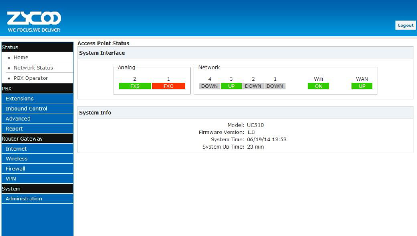
2.1 Home
The default login URL is http://192.168.1.1:9999
After system login, the home page will display status of the system interface and system
information including model, firmware version and running time.
System Interface: Connecting Status of Interfaces.
If an Analog module is connected, “FXO” or “FXS” will be displayed at the appropriate position. If
no Analogue module is connected then “N/A” will be displayed.
If Ethernet is connected on either LAN or WAN,“UP” will be displayed for the relevant port. If no
connection is detected on the port, “DOWN” will be displayed.
If Wi-Fi is enabled, “ON” will be displayed and if not enabled “OFF” is displayed.
System Info: Displays device model, system version, system current time and running time.
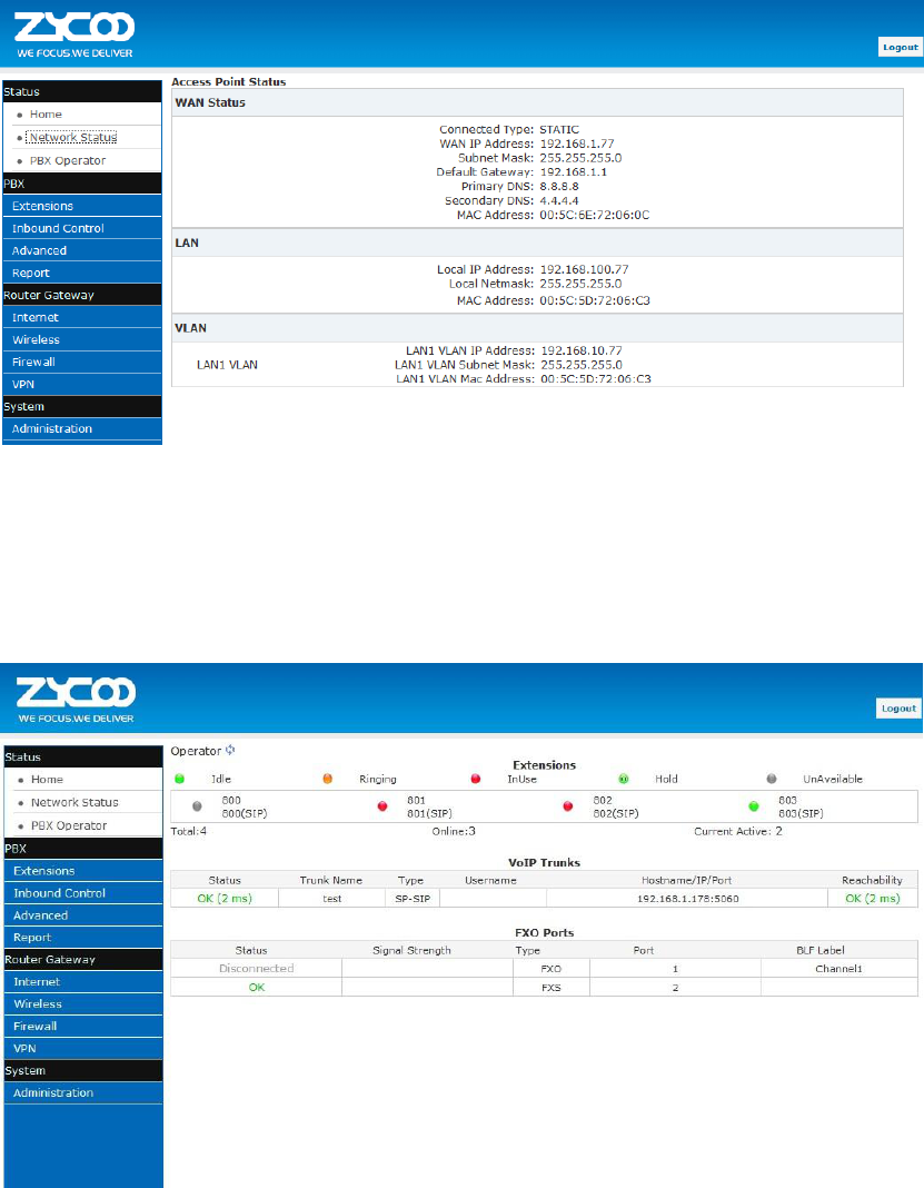
2.2 Network Status
Network Status displays the network configuration of the system, including WAN, LAN, VLAN.
The network connection supports STATIC, DHCP and PPPoE. The relevant information will be
displayed after configuration from【Router Gateway】【Internet】.
The example below shows a typical configuration:
8
2.3 PBX Operator
On this page, the extension status, trunk status and module status will be displayed.
Extensions :Extensions’ status, including Idle, Ringing, InUse, Hold, and UnAvailable.
VoIP Trunk: If there is no trunk, you will be reminded that “No VoIP Trunk Defined” and “Click
Here to Create Trunk”.
FXO Ports : If there is no module inserted, then nothing will be displayed here; if there is other
module inserted, the other module connection status will be displayed here.
9
Chapter 3 PBX
3.1 Extensions
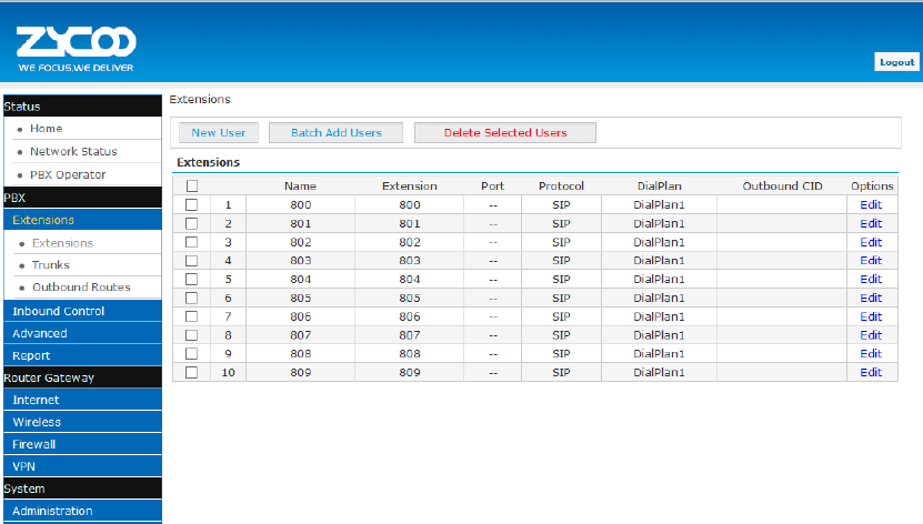
3.1.1 Extensions
UC510/520 support SIP/IAX2 and analog extensions. You can add new users one at a time or by
using the batch add users feature. All extensions are configured on this page.
Click 【Extensions】【Extensions】to configure:
Click【New User】to see the extension configuration interface as below:
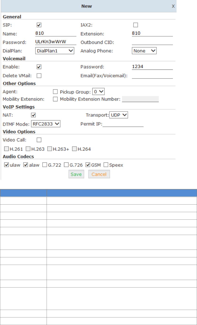
10
Reference:
Item
Explanation
SIP/IAX2
Choose extension protocol.
Name
Extension Name (English Character Only), e.g.: Tom.
Extension
Extension Number connected to the phone, e.g.: 888.
Password
Same password as voicemail. (4-16 digits, e.g.:123456)
Outbound CID
Override the caller ID when dialing out with a trunk.
Dial Plan
Please choose the Dial Plan which is defined in the menu “Outbound
Routes”.
Analog Phone
Please choose the relative FXS port for your analog phone.
Enable
Enable the voicemail account
VM Password
Set password for Voicemail. For security reasons, do not use the
extension number or any easy combination for example "1234"
Delete VMail
Delete voicemail from the PBX after it’s sent by email.
Email
(FAX/Voicemail)
Extension user’s email address to receive email messages with attached
fax or voicemail (you need configure the fax to email/voicemail options),
e.g.: Tom@gmail.com
Agent
Set this extension user as agent.
NAT
Check this option if extension user or the phone is located behind the
11
router.
Pickup Group
Select the Pickup Group which the extension user belongs to.
Mobility Extension
If this option is checked, you must set mobile extension number. User
can make calls to the PBX server with this mobile number, and have all
rights of this extension, e.g.: Outbound Call, Internal Call, or listen to
voicemail.
Transport
Select the Transport Protocol: UDP, TCP
DTMF Mode
Default DTMF is rfc2833. It can be changed if necessary.
Video Call
Check to enable video calling for this extension and select the video
codecs you require.
Permit IP
Set device IP address or subnet permitted to register extensions with
the PBX.
E.g.:192.168.1.77/255.255.255.255 or 192.168.10.0/255.255.255.0.
Devices with other IP addresses are not allowed to register extension to
the PBX.
Audio Codecs
Select what audio codecs you require.
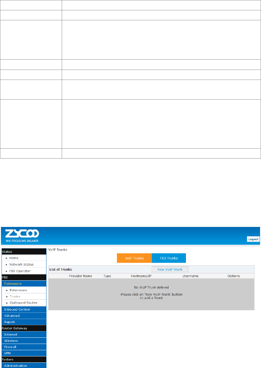
3.1.2 Trunk
If you want to set up an outbound route connected to the PSTN (Public Switch Telephone
Network) or VoIP provider, please configure on this page:
Click【Extensions】【Trunks】:
UC510/520 supports two kinds of trunks for your choice: VoIP Trunk and FXO trunk.
VoIP Trunks
Click【VoIP Trunk】【New VoIP Trunk】:
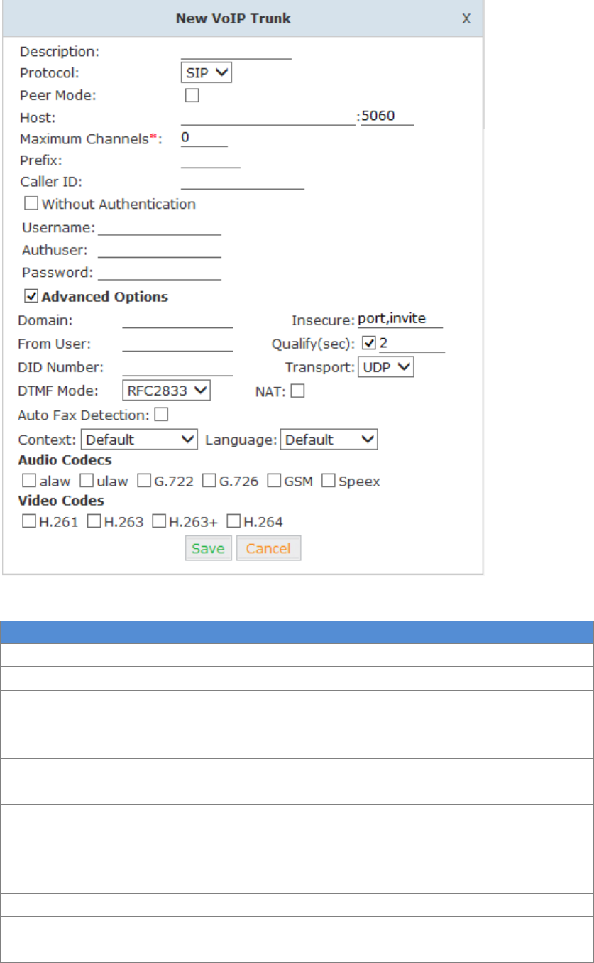
12
VoIP Trunks Reference:
Item
Explanation
Description
Description of SIP trunk.
Protocol
Select protocol for outbound route, SIP or IAX2.
Host
Set host address (provided by VoIP Provider).
Maximum Channels
Set maximum channels for simultaneous call. (Only for outbound call;
“0” = no limitation).
Prefix
The prefix will be added in front of your dialed number automatically
when the trunk is in use.
Caller ID
This Caller ID will be displayed when user makes outbound call.
Note: This function must be supported by service provider.
Without
Authentication
If your trunk is static IP based and does not require a registration string
when connecting the CooVox IP PBX, check this option.
Username
Username provided by VoIP Provider.
Password
Password provided by VoIP Provider.
Advanced Options
Advanced options for this trunk, e.g.: codecs, language, etc.
The outbound trunk will be in the list of VoIP Trunks when the trunk is added successfully.
13
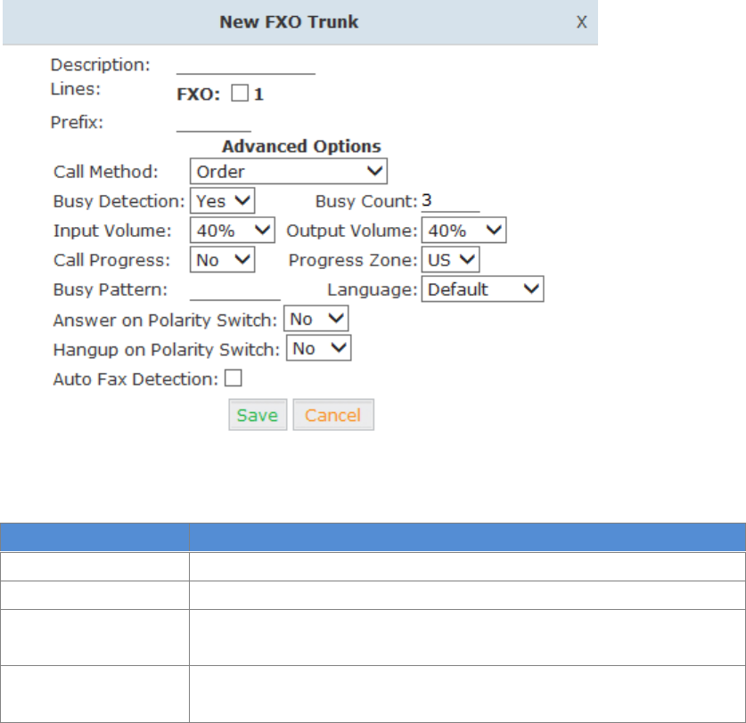
FXO Trunk
Click【FXO Trunk】【New FXO Trunk】:
FXO Trunk Reference:
Item
Explanation
Description
Description for this trunk.
Lines
Check one or two channels (FXO) to be included in this trunk group
Prefix
The prefix will be added to the dialed number automatically when this
trunk is in use.
Advanced Options
Advanced Options for this trunk, e.g.: Call Method, Busy Detection,
etc.
Select one or more of the available channels to be used for this trunk group.
Note: each channel can only be included in one trunk group. If no channels appear then all
available channels are already defined.
3.1.3 Outbound Routes
Outbound Routes are used to define which trunk groups are used by a specific extension when
placing outbound calls. If you don't allow an extension user to place external calls, please ignore
this section.
Please configure on this page: 【Basic】【Outbound Routes】
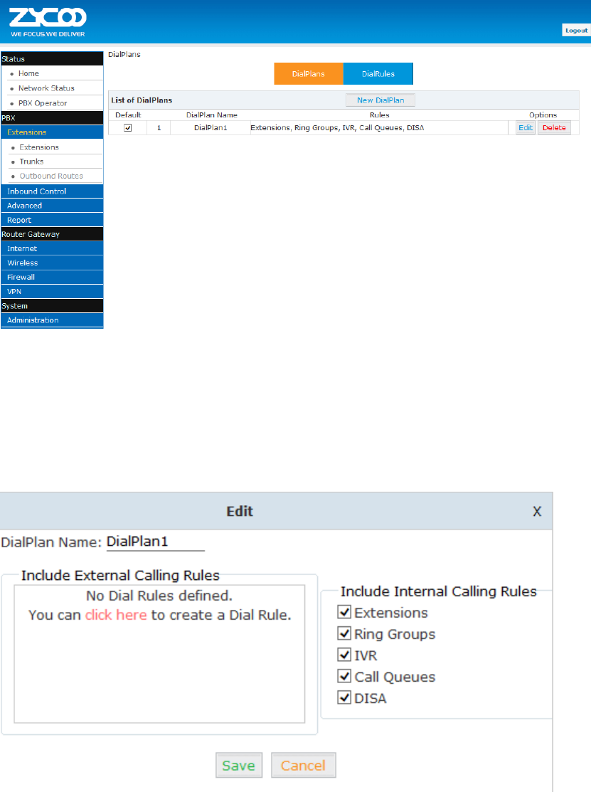
14
You can configure the basic match pattern of outbound routes and create different dial plan on
this page. Create as many different dial plans as you need to determine how you need extensions
to be allowed to make calls. For example, create “InternalDialPlan” to include all Internal Calling
Rules but do not select any outbound dial rules. Select “InternalDialPlan” for all extension users
that do not need the ability to make external calls.
Click【DialPlans】【New DialPlan】:
You can create one or more DialRules for DialPlans from the DialRules page:
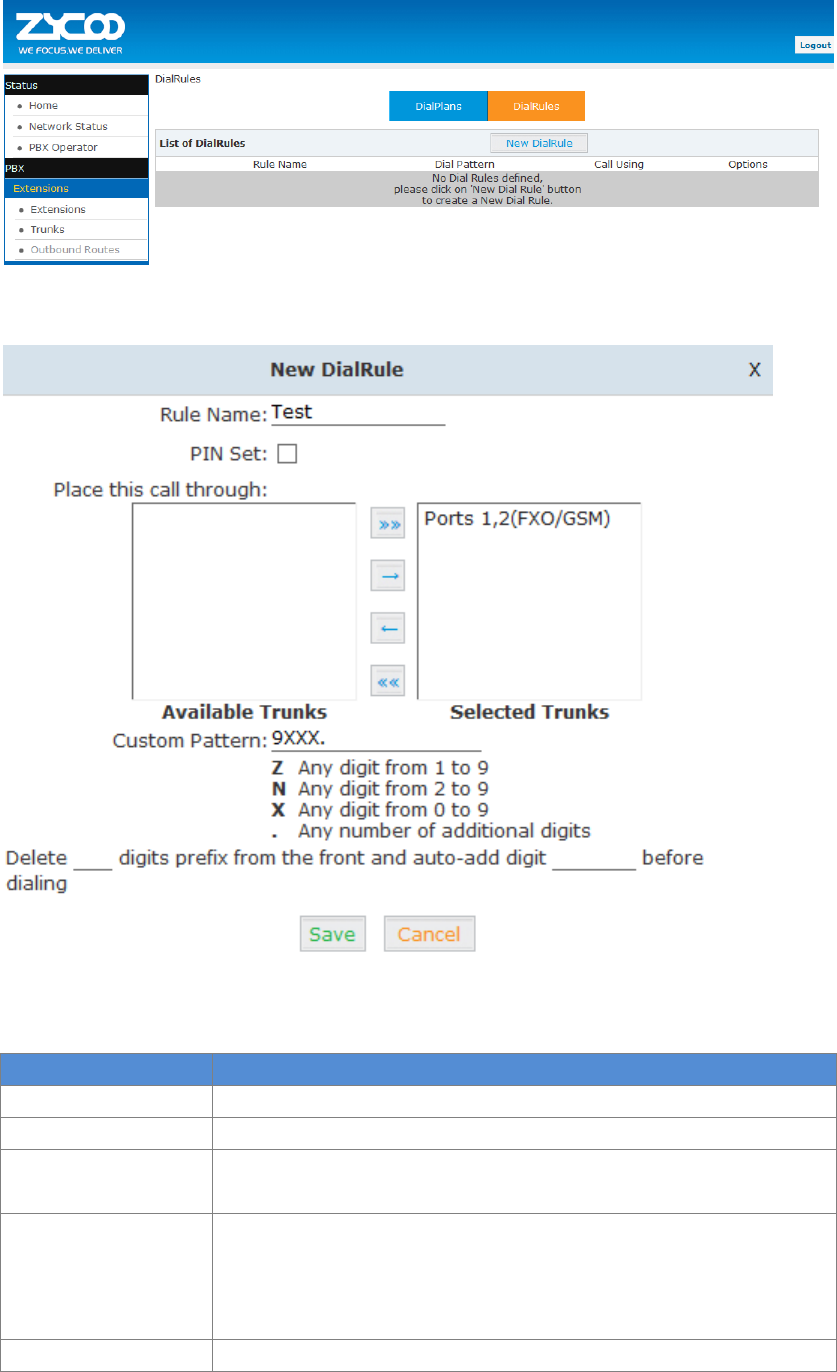
15
Click【DialRules】【New DialRule】to create a new Dial Rule
Reference:
Item
Explanation
Rule Name
Define the name for the dial rule.
PIN Set
Input this PIN when you use this dial rule.
Place this call through
Select one of the trunk groups that have been set up to use for this
dial rule
Custom Pattern
N any digit from 2 to 9
Z any digit from 1 to 9
X any digit from 0 to 9
. One or more digits
Delete[ ]digits prefix
Define how many digits will be deleted from the dialed number.
16
For example, user dialed 94166445775 and you selected to delete 1
digit, then 4166445775 is sent out to the trunk.
Auto-add digit[ ]
If add digit “9”, when dial 12345, 912345 will be sent.
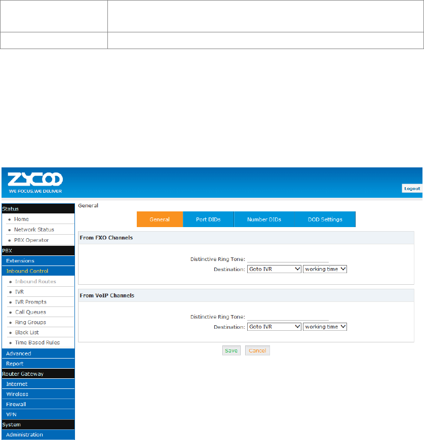
3.2 Inbound Control
3.2.1 Inbound Routes
Click【Inbound Control】【Inbound Routes】
General
Distinctive Ring Tone:mapping the custom ring tone file, e.g.: Set distinctive ring tone as
“External”, the phone will play this ring tone when receiving the call.
Note: The phone must support such feature as well.
Select all calls coming in on a specific port (FXO/VoIP) and select which destination (Extension
User, IVR, Queue, Conference Bridge, IVR, etc) should answer those calls. Setting the label will
assign this label to be displayed.
Port DIDs
To have incoming calls from a PSTN trunk port (FXO trunk) answered by a specific extension user,
call queue, conference bridge, or IVR, please configure here:
Click【Port DIDs】【New Port DIDs】:
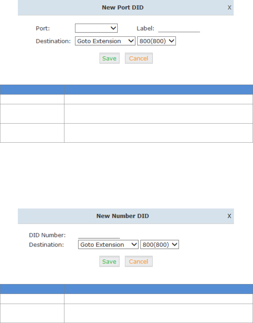
17
Reference:
Item
Explanation
Port
Select the port
Label
Set a label for the port. Incoming calls from this port will display the
specified label.
Destination
Incoming calls will be answered by the specified destination.
(extension user, call queue or IVR etc)
Number DIDs
If you want to set the destination of inbound calls through VoIP and E1/T1 Trunks based on the
incoming DNIS (dialed number or DID), you can specify the DID and destination (user extension,
queue or IVR, etc) from the following diagram.
Click【Number DID】【New Number DID】:
Reference:
Item
Explanation
DID Number
Set DID Number
Destination
Incoming calls will be answered by the specified destination
(extension user, call queue or IVR etc)
DOD Settings
To configure outbound calls from user extensions to answer with specified destinations (user
extension, queue, IVR, etc) , please click【DOD Settings】【New DOD】:
18
Reference
Item
Explanation
DOD Number
Set the DOD(direct outbound dial) number, and use it to match the
Caller ID
Destination
Incoming calls will be answered by the specified destination
(extension user, call queue or IVR etc)
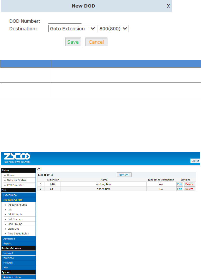
3.2.2 IVR
IVR (Interactive Voice Response) or Automated Attendant will allow callers to select from a
specific set of options by pressing the selected digit on their telephone dialpad.
Click【Inbound Control】【IVR】:
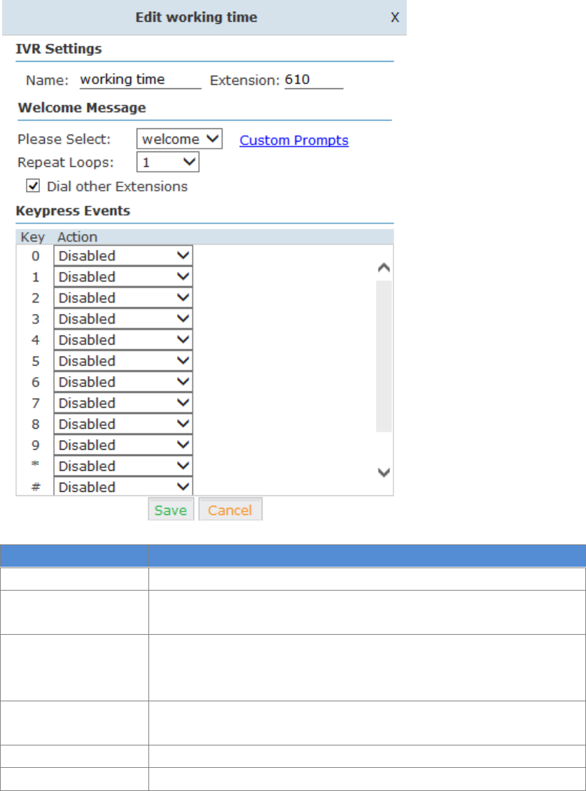
19
Click【NewIVR】to create a new IVR:
Item
Explanation
Name
Enter a descriptive name for the IVR
Extension
Enter a unique extension or IVR number. This number is used to
access the IVR from an internal extension
Please Select
Select the IVR prompt that will provide the caller with instructions on
what options are available. To configure the prompt in this page:【IVR
Prompt】
Repeat Loops
Loop times to repeat playing the IVR prompt if the caller does not
select an option
Dial Other Extension
Allow user to dial other extensions instead of the listed options
Keypress Event
Select the available options beside the designated digit
20
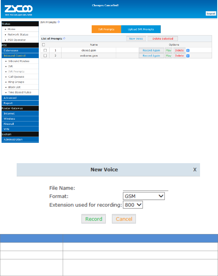
3.2.3 IVR Prompts
IVR prompts can be customized recorded by any extension registered to the PBX or they can be
uploaded from the “Upload IVR Prompt” section below:
Click【IVR Prompts】【New Voice】to create new IVR prompt:
Item
Explanation
File Name
Define a name for this voice file
Format
Select the voice format GSM / WAV(16bit) supported only
Extension used for
recording
Select the extension which is used for recording the IVR prompt
Click【Record】, the extension will ring, and the prompt can be recorded after answering the
phone.
To hear the existing recording, please click【Play】:
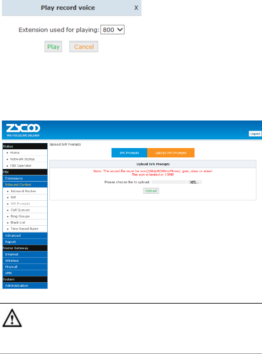
21
Select the extension, click【Play】, the selected extension will ring, and you will hear the recorded
prompt after picking up the phone.
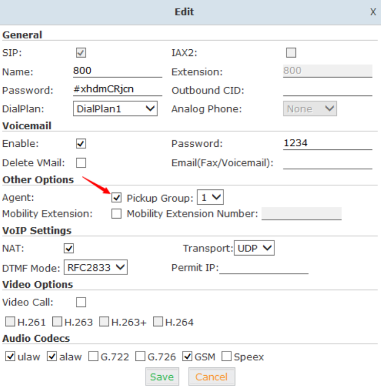
Upload IVR prompt
Click【Upload IVR prompt】【Upload】:
Notice:
UC510/520 supports custom audio files in wav, gsm, ulaw, alaw format.
Recordings must be smaller than 15MB.
22
3.2.4 Call Queue
Create Agent
To allow a user to be an agent in a Call Center queue, please check the “Agent” option for that
specific user extension.
Click【Basic】【Extension】【Edit】the extension you want to configure:
Step1:Tick【Agent】and【Save】
23
Step2: Click【Inbound Control】【Call Queues】
Reference
Item
Explanation
Queue Number
Define an extension number to identify the queue.
Label
Define the label for the queue.
Ring Strategy
RingAll--Ring all available agents until one answers( default)
RoundRobin – Starting with the first agent, ring the extension of each
agent in turn until the call is answered.
LeastRecent – ring the extension of the Agent who has least recently
received a call
FewestCalls – ring the extension of the Agent who has taken the fewest
number of calls.
Random – ring the extension of a random Agent.
RRmemory -- RoundRobin with Memory, like RoundRobin above, except
instead of the next call starting with the first agent, the system
remembers which extension was called last and begins the round robin
with the next agent
Agent
Check each agent that is to be a member of this specific Call Center
Queue.

24
Reference:
Item
Explanation
Agent TimeOut(sec)
Specify the number of seconds to ring an agent’s extension before
sending the call to the next Agent (based on Ring Strategy).
Auto Pause
If an Agent’s extension rings and the Agent fails to answer the call,
automatically pause that agent so they stop receiving calls from the
queue.
Wrap-Up-Time(sec)
This is the amount of time in seconds that an agent has to complete
work on a call after the call is disconnected.
(Default is 0, which means no wrap-up time.)
Max Wait Time(sec)
Calls that have been waiting in the queue for this number of seconds
will be sent to the “If not answered” destination.
Max Callers
Max number of callers who are allowed to wait in the queue. (Default is
0, which means no limitation.). With this number of callers in the queue
already, subsequent callers will be sent to the “”If not answered”
destination.
Join Empty
Allow callers to enter the Queue when no Agents are available. If this
option is not defined, callers will not be able to enter Queues with no
available agents - callers will be sent to the ”If not answered”
destination.
Leave When Empty
If this option is selected and calls are still in the queue when the last
agent logs out, the remaining callers in the Queue will be transferred
to ”If not answered” destination. This option cannot be used with Join
Empty simultaneously.
Auto Fill
Callers will be distributed to Agent automatically.
Report Hold Time
Report the hold time of the next caller for Agent when the Agent is
answering the call.
Frequency(sec)
Repeat frequency to announce the hold time for callers in the Queue.
(“0” means no announcement).
Announce Hold
Time
Announce the hold time. Announce (yes), do not announce (no) or
announce once (once), it will not be announced when the hold time is
less than 1 minute.
Repeat
Frequency(sec)
Interval time to play the voice menu for callers.(“0” mean not to play).
Announcement
Prompt
Select a prompt as the Announcements Prompt from the IVR Prompts.
25
3.2.5 Ring Groups
A Ring Group (sometimes called a Hunt Group) is a way to ring a collection of extensions by
dialing a single extension number. The methodology used to ring that collection of extensions is
called the ring strategy. Once the timeout (number of seconds) is reached, the call will then be
directed to the “if not answered” or failover destination.
Click【Inbound Control】【Ring Groups】to configure a Ring Group:
Click【New Ring Group】to create a new ring group:
26
Reference:
Item
Explanation
Name
Define a name for the Ring Group
Label
Define the label for the Ring Group.
Ring Strategy
Select “Ring All” or “Ring in order”
Ring Group
Members
Select the Ring Group Member from “”
If not answered
You can choose to forward the call to extension, voicemail, ring group, IVR
or hang up if no answered.
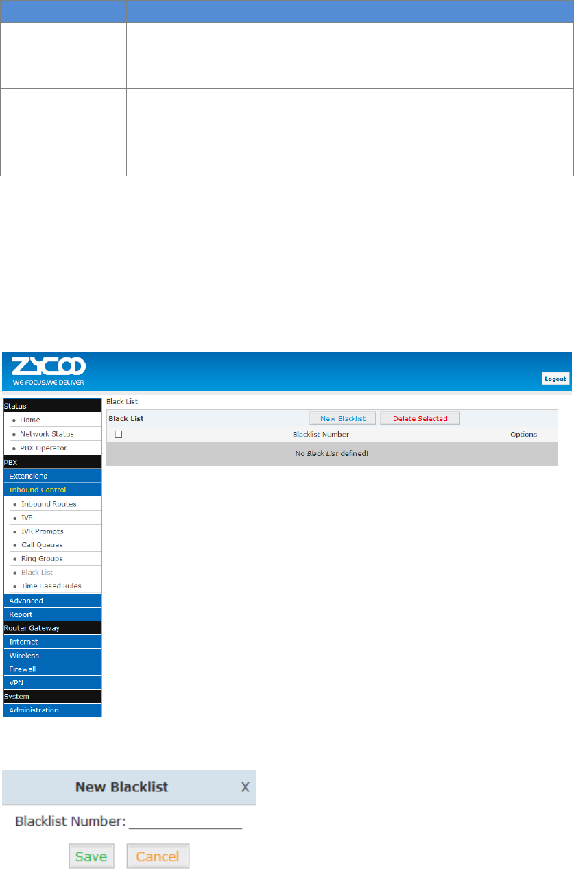
3.2.6 Blacklist
The Blacklist feature allows the blocking of specific phone numbers by Callerid; such as the
insurance sales, credit card sales who interrupted your work, you can add their numbers to the
blacklist.
Click【Inbound Control】【Blacklist】to configure:
Click【New Blacklist】to create a new Blacklist:
Input the caller ID in the space provided. Once configured, future calls from this caller ID will be
blocked.
27
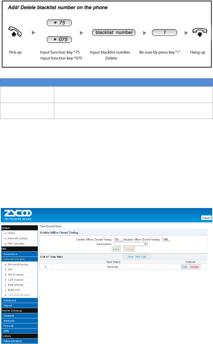
To maintain this list of blocked numbers, see the instructions in the following diagram:
Reference:
Item
Explanation
*75
When the registered extension user inputs *75 + blacklist number, this
number will be added to the list of Blacklist Numbers.
*075
When the registered extension user inputs *075+blacklist number, this
number will be deleted from the list of Blacklist Numbers.
3.2.7 Time Based Rules
Time Based Rules can help a company to distribute calls to the right person in the specified hour.
For example, BusinessHours.
Select the start& end time, start&end day, start & end dates and/or start & end month. When an
inbound call is processed, if the current time of the PBX is within these parameters, then the call
will go to the “if time matches” destination. If the current time of the PBX is out of these
parameters, then the call will go to the “if time does not match” destination.
Please set from this page: 【Inbound Control】【Time Based Rule】:
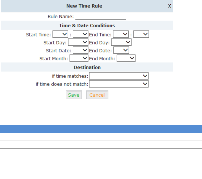
28
Click【New Time Rule】to create a new Time Rule
Reference:
Item
Explanation
Rule Name
Define the name for this Time Rule.
Time&Date Conditions
Set parameters for Time/Day/ Date/ Month.
Destination
Select destination if time matches or does not match the above
condition. For example for BusinessHours, “if time matches”, select
operator extension during BusinessHours. If out of business hours,
select Operator voicemail as “if time does not match” destination.
29
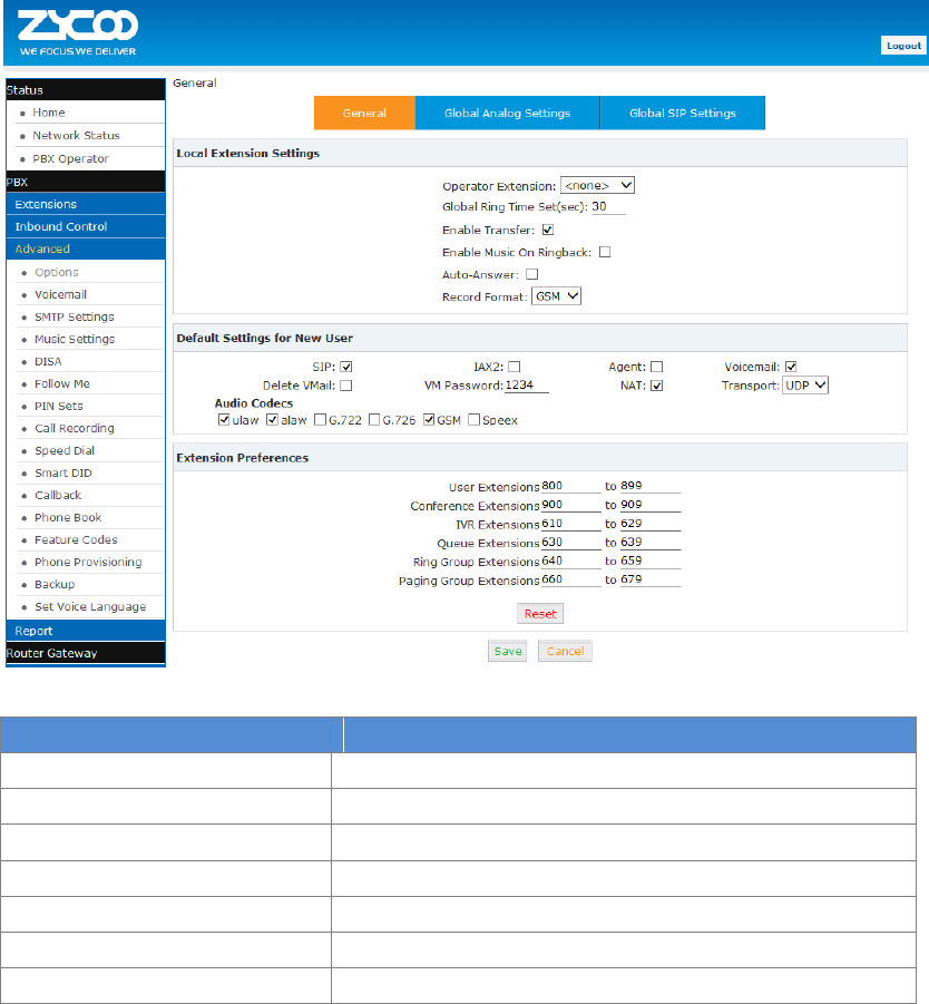
3.3 Advanced
3.3.1 Options
General
Default settings for existed extension and new extension.
Click【Advanced】【Options】【General】:
Reference
Item
Explanation
Operator Extension
Set extension number for Operator.
Global RingTime Set
Set RingTime for every extension.
Enable Transfer
Check to enable Transfer.
Enable Music On Ringback
Check to enable Music On Ringback.
Record Format
Set the format for recording files. (GSM / WAV only)
Defaut Setting for New User
Check to enable the default settings.
Extension Preferences
Set the rule for extensions.
30
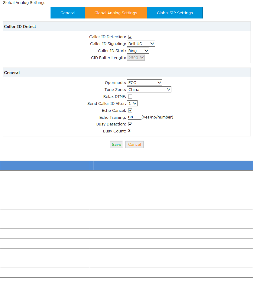
Global Analog Settings
Click【Advance】【Options】【Global Analog Settings】:
Reference:
Item
Explanation
Caller ID Detection
Enable/Disable Caller ID Detection
Caller ID Signaling
Select the mode of Caller ID Signaling.
Caller ID Start
Ring--Caller ID start before ring.
Polarity--Caller ID start when polarity reversal starts.
CID Buffer Length
Default CID Buffer Length
Opermode
Set the Opermode for FXO/GSM Ports.
ToneZone
Select the ToneZone in your country.
Relax DTMF
Enable/Disable Relax DTMF inspection.
Echo Cancel
Enable/Disable Echo Cancel
Echo Training
Set Echo Training (default unit: ms)
Busy Detection
Enable/Disable Busy Detection.
Busy Count
Count the Busy Detection. It will be active when enable Busy
Detection.
31
Global SIP Settings
Global SIP Settings is appropriate for advanced administrators. Please contact our technical
support department before modifying anything in this section.
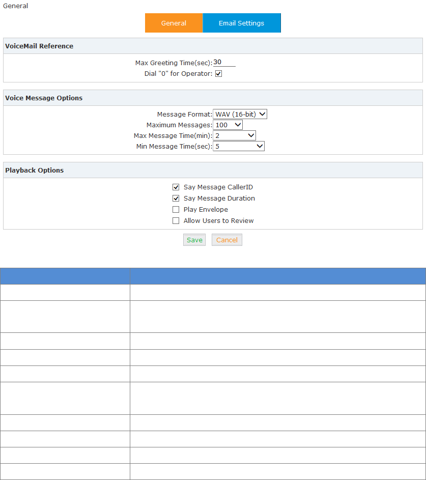
3.3.2 Voicemail
Voicemail is used to convey a caller's recorded audio message to a recipient when the recipient is
not at seat or busy on the phone.
When configuring your email settings, first you need to set the voicemail reference and voice
message information… as below.
Click【Advanced】【Voicemail】【General】:
Reference
Item
Explanation
MaxGreeting Time(sec)
Maximum recording length for voicemail greetings
Dial "0" for Operator
Select this option to allow callers to dial "0" to transfer out of
voicemail to the Operator.
Message Format
Save the voice message at this format, WAV(16-bit) or Raw GSM.
Maximum Messages
Maximum voicemail messages allowed.
Max Message Time(min)
Maximum Time for each message allowed.
Min Message Time(sec)
MinimumTime for each message. The message will be deleted
automatically if the time is less than the min. message time.
Say Message CallerID
Play the Caller ID of the caller before playing the voice message.
Say Message Duration
Play the message duration before playing the voice message.
Play Envelope
Play the date, time and caller ID for the voicemail message.
Allow Users to Review
Check this option to allow users to review the voice message.
32
Then you need to configure the template for voicemail emails as below.
Click【Advance】【Voicemail】【Email Settings】:
Reference:
Item
Explanation
Attach voicemail to Email
The voicemail will be sent as attachment to the user’s Email.
Sender Name
The sender’s name will be displayed when you receive the
Email.
From
Mailbox to send email.
Subject
Subject of the Email.
Message
Input the Email template.
3.3.3 SMTP Settings
An SMTP server is required to allow email messages to be sent to users with attached voicemail
and fax-mail messages. The system supports connection to cloud based SMTP service providers
such as google. Configure your SMTP server as follows:
Click【Advance】【SMTP Settings】:
33
Reference:
Item
Explanation
SMTP Server
You must set SMTP Server address or domain connected to the
CooVox IP PBX, which is used for sending the voice message to
Email.
Port
Port number for SMTP server. Default is 25, and it will be changed
to 465 when you enable SSL/TLS.
SSL/TSL
Enable SSL/TLS.
Enable SMTP
Authentication
If your SMTP server needs authentication, please enable this
option, and configure the following.
Username
Input username of your Email.
Password
Input password of your Email.
Click【Send Test】after configuration, the following diagram will be displayed to ask you to input
the Email for receiving.
Specify the email address and click【Send】to send the test email. Verify that email was
successfully sent or not. If no email is received, please modify the SMTP settings and try again.
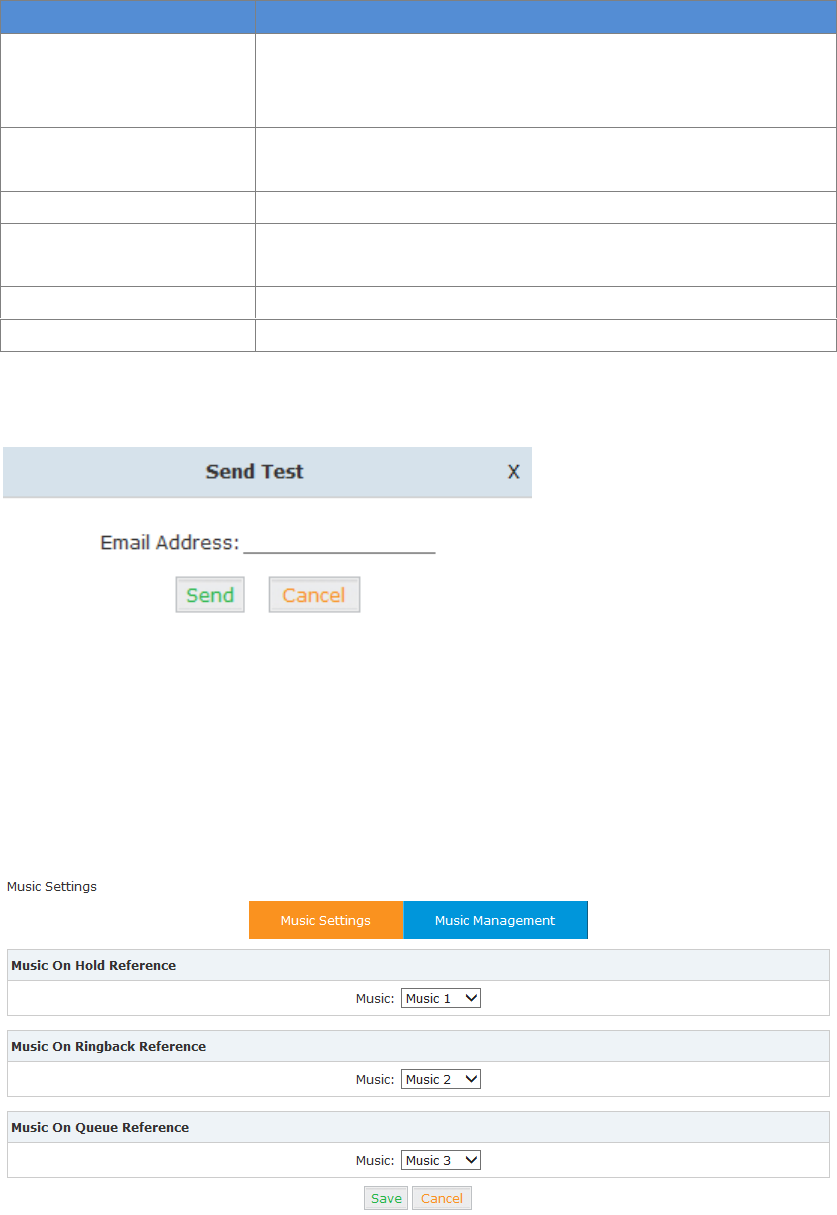
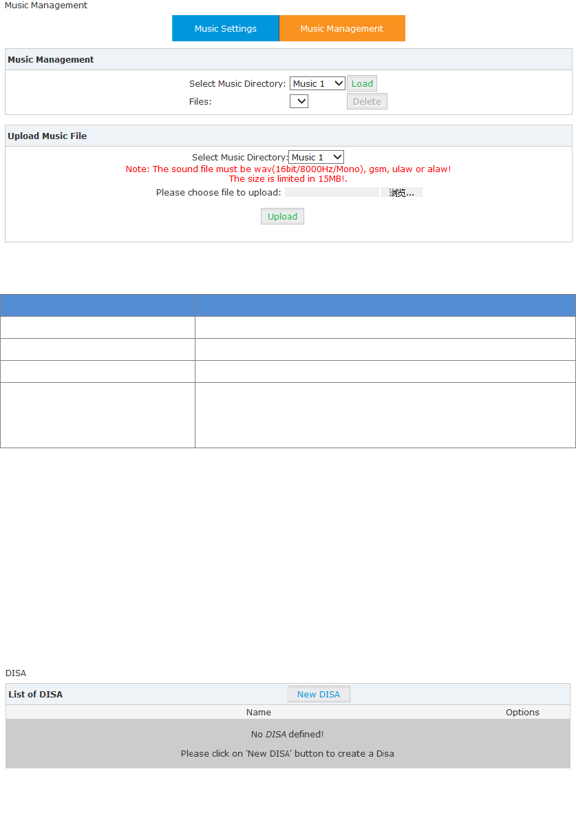
3.3.4 Music Settings
Management of Music on Hold, Music on Ringback, Music on Queue.
Click【Advance】【Music Settings】:
Select the different music file for different Music.
34
Music Management
【Advance】【Music Settings】【Music Management】
Reference:
Item
Explanation
Select Music Directory
Select which Music Directory you wish to load.
File
Display music name under the music file, you can delete it.
Select Music Directory
Select the file where you want to save your uploaded music.
Please choose file to upload
Select the music you want to upload.
Note: music file must be wav (16bit/8000Hz/Single), gsm,
ulaw or alaw, and less than 15MB.
3.3.5 DISA
This feature allows an authorized user to call into the PBX and then place an outbound call using
another trunk. For example, an employee working out of the office who needs to make an
international call using trunks connected to the PBX. By calling the DISA number, after PIN
authentication, the caller hears dial tone and can dial the call.
Please configure as below.
Click【Advance】【DISA】:
Click【New DISA】to create a new DISA
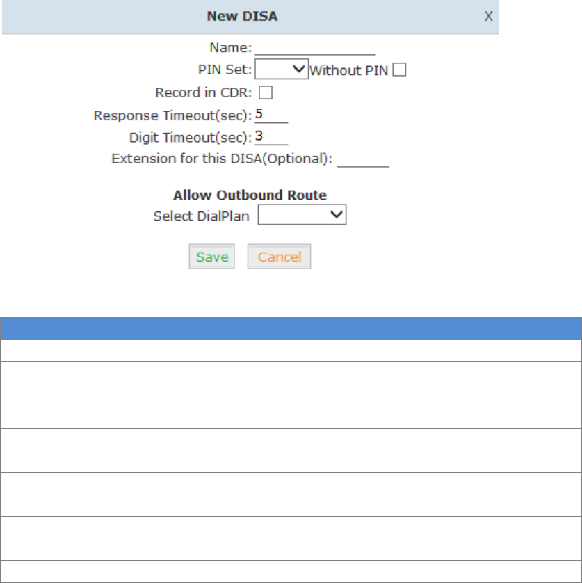
35
Reference
Item
Explanation
Name
Define a name for DISA.
PIN Set
User will be prompted to input this number when PIN
Authentication is needed.
Record in CDR
Check to record.
Response Timeout(sec)
The maximum time for waiting before hanging up if the dialed
number is incomplete or invalid. Default is 10 seconds
Digit Timeout(sec)
The maximum interval time between digits when typing
extension number. Default is 5 seconds.
Extension for this
DISA(Optional)
If you want to access DISA by dialing an extension, you can
define an extension number for this DISA.
Select DialPlan
Select the DialPlan for this DISA.
3.3.6 Follow Me
This feature allows callers to automatically be forwarded to one or more internal extensions
and/or one or more external phone numbers when the call is not answered at the primary
extension.
Please configure as below.
Click【Advanced】【Follow Me】【New Follow Me】:
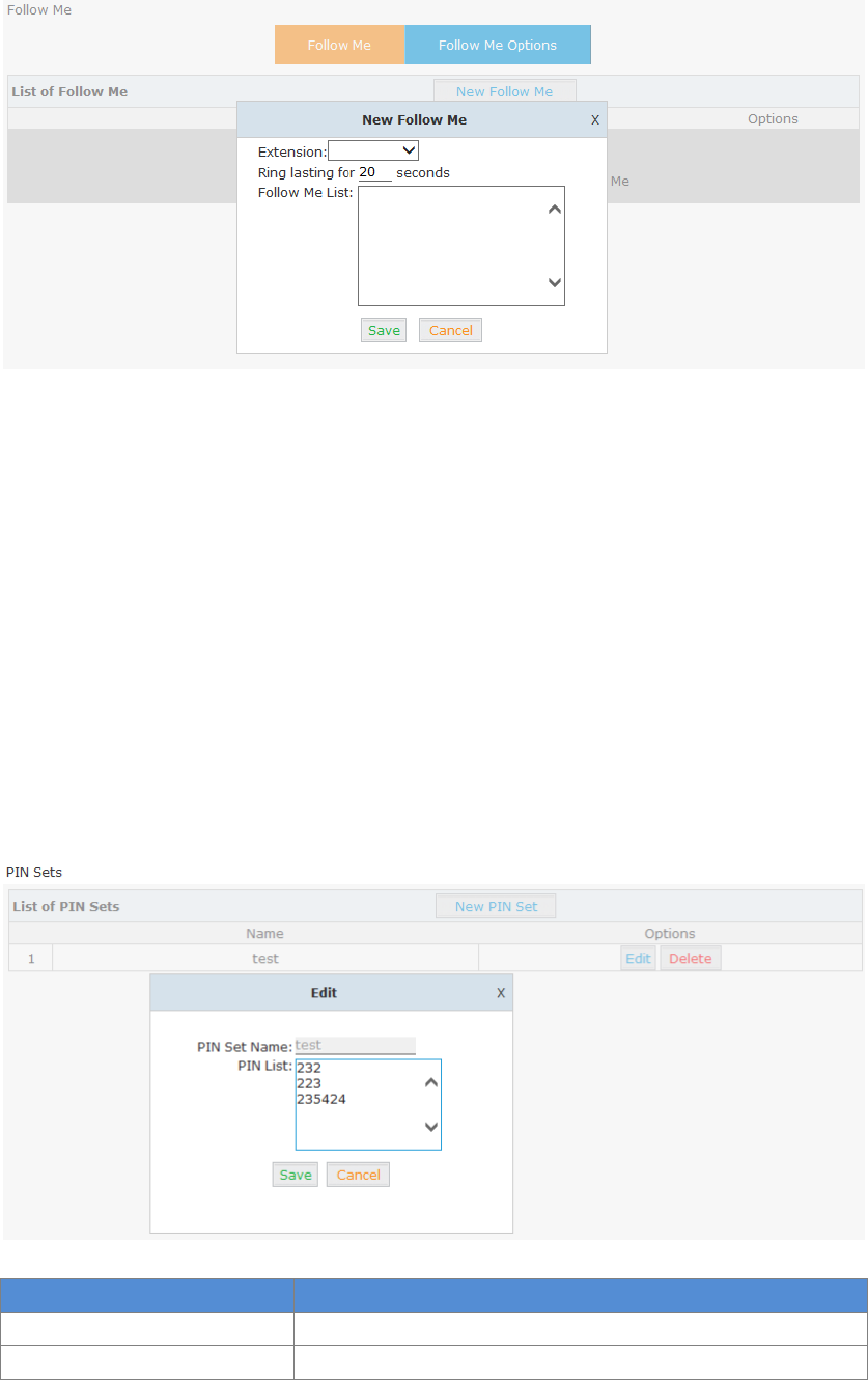
36
Select an extension, set the ring duration, and add the numbers in the Follow Me List; 【Save】
and 【Activate】.
List Format: Extension Number, Ring Duration
E.g.: 806,30
808,20
806 rings, after 30 seconds, the call is going to 808
3.3.7 PIN Sets
This feature allows an administrator to specify a list of PIN codes in a PIN Set. These PIN codes
can then be used to secure an Outbound Call Route, ensuring that users must enter the PIN
selected to be able to make an outbound call (e.g. for long distance or international calling).
Please configure as below.
Click【Advanced】【PIN Sets】【New PIN Set】:
Reference
Item
Explanation
PIN Set Name
Define the name for this PIN Set
PIN Set
Define PIN codes in this list
37
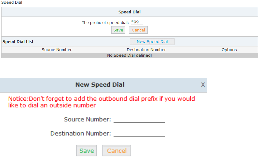
3.3.8 Speed Dial
This feature allows the user to place a call by pressing a reduced number of keys. This function is
particularly useful for phone users who dial certain numbers on a regular basis.
From the example here, it allows setting up system wide speed dial numbers that translate a
feature code (*99) plus a two-digit code (00-99) into an external phone number.
Click【Advanced】【Speed Dial】【New Speed Dial】:
Click 【New Speed Dial】to create a new speed dial.
E.g.: prefix is *99 , speed number is 00, destination telephone number is 85337096.
When dial *9900, the call is going to 85337096 automatically.
3.3.9 Smart DID
Smart DID is defined and developed by ZYCOO directly. It’s allows the callee to reach the caller
directly when calls back via PBX. E.g.: Caller A makes an outbound call to the callee B, but B is out
of office and cannot receive the call; When callee B backs to the office, he/she can make the call
back to the caller A directly even he/she doesn’t know the caller A’s extension number.
Click【Advanced】【Smart DID】:
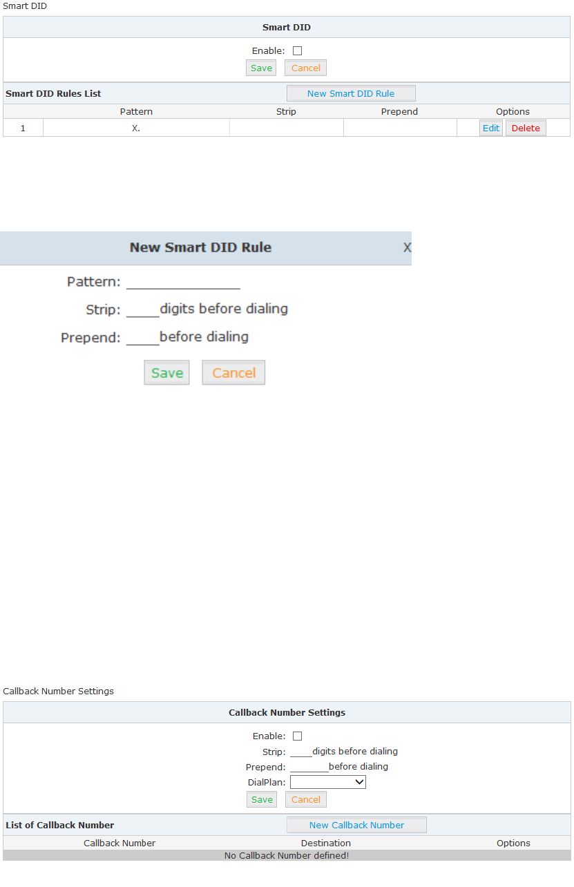
38
Check “Enable” and “Save” to make this function efficient.
Click【New Smart DID Rule】to display the following diagram:
Input the pattern and define how many digits need to be stripped or prepended, then click
“Save”“Activate”.
3.3.10 Callback
This feature allows an external caller to place an inbound call to the PBX. The inbound call will be
disconnected and subsequently the PBX will place an outbound call back to this number and
forwarded to defined destination after the call is connected.
Please configure as below.
Click【Advanced】【Callback】:
Enable this function; select DialPlan, and define the callback rule (strip digits or prepend prefix).
Click【New Callback Number】to add callback number.
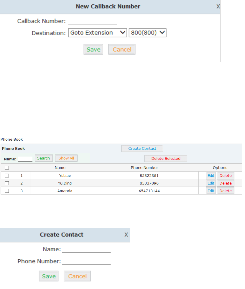
39
Input callback number and define the destination.
3.3.11 Phone Book
When an incoming call’s Caller ID matches a number in the phone book, the name of matched
number will be displayed. Please configure as below.
Click【Advanced】【Phone Book】:
Click 【Create Contact】to create a new contact
3.3.12 Feature Codes
Feature codes are short dial codes that when manually dialed or programmed into a function key
on your phone will allow you to perform actions quickly.
Click【Advanced】【Feature Codes】to see the following diagram, and you can define the code
for each feature.
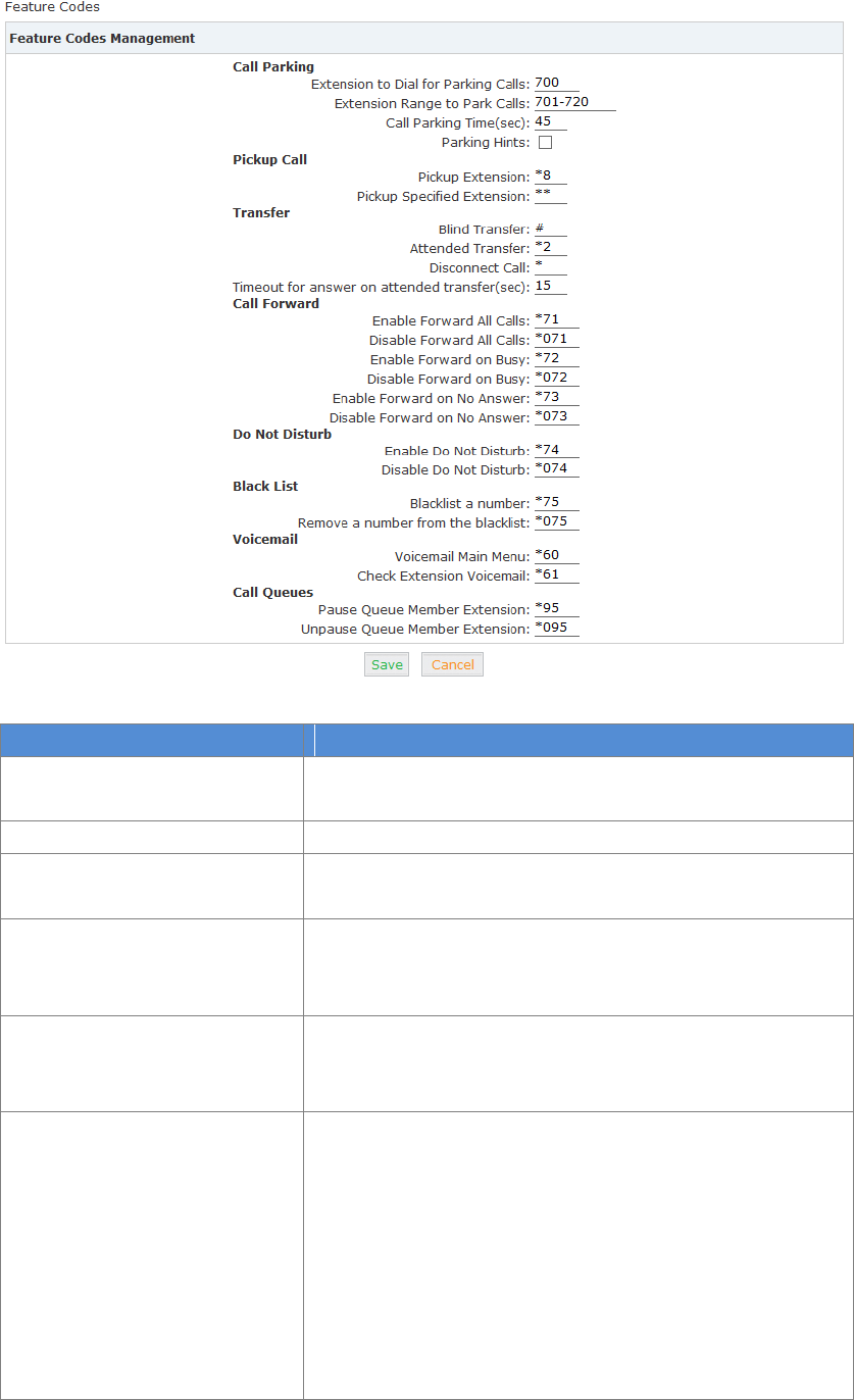
40
Reference:
Item
Explanation
Extension to Dial for Parking
Calls
Define an extension for parking calls.
Extension Range to Park Calls
Define the extension range for parking calls. (e.g.: 701-720)
Call Parking Time(sec)
Define the time for parking calls. UC510/520 will return the
call to the extension after this time is expired.
Pickup Extension
This feature code will pick up a call given that the callers
extension and the ringing extension are in the same pickup
group and call group.
Pickup Specified Extension
This feature code allows a caller to pickup a call ringing on
the specified extension. Default: Dial**+extension number
to pickup the specified extension.
Blind Transfer
To Allow unattended or blind transfer while on a call based
on the following steps:
1.While on a call with caller “A”, the user dials the blind
transfer key sequence (in this case “#”). The system places
the original call with “A” on hold, says "Transfer" then gives a
dial tone.
2. Dial the transferee extension or phone number you wish
to transfer the call to “B” and hangup the phone.
3.The original caller “A” is transferred immediately to the

41
transferee “B” and “B” see the callerid of “A”.
Attended Transfer
To allow attended or supervised transfer while on a call
based on the following steps:
While on a call with caller “A”, the user dials the supervised
transfer key sequence (in this case “*2”). The system places
the original call with “A” on hold, says "Transfer" then gives a
dial tone.
dial the transferee extension or phone number you wish to
transfer the call to “B” and wait for “B” to answer the phone
and talk to “B” to introduce the call.
If “B” does not wish to take the call, “B” can hang up the call
and you are returned to your call with “A”.
If “B” wishes to accept the call, you hang up the phone and
caller “A” is transferred to the transferee “B”.
If the call goes to voicemail or you wish to abort the transfer,
simply press the “disconnect call” key sequence (in this case
“*”) and the transfer will be aborted and you will be back on
the call with the original caller “A”.
Disconnect Call
Disconnect the current transfer call (for Attended transfer).
Timeout for answer on attended
transfer(sec)
Set the timeout value
One Touch Recording
Configure the function key for One Touch Recording
Call Forward
Enable/Disable Call Forward and the settings of function
keys for different forward modes.
Do Not Disturb
Enable/Disable “Do Not Disturb”
Blacklist
Add/Delete blacklist number.
Voicemail
Configure the function keys for entering voicemail and check
extension voicemail.
Pause Queue Member
Extension
Pause the agent, and the agent cannot receive the call.
Unpause Queue Member
Extension
Un-pause the agent, and the agent can receive the call.
3.3.13 IP Phone Provisioning
When deploying large numbers of IP Phones, it is time consuming to have to configure each
extension manually. UC510/520 allows certain IP Phones to be auto-provisioned and therefore all
supported phones can be auto-provisioned. How amazing is this for enterprise!
To achieve this, please record the MAC, extension number, and username of each phone in the
required format (please take reference of the auto provision script file model for details), then
import the formatted file, once the phone is connected to the local network, it will get the
extension number and password automatically. There are two operation methods to fulfill this
function: DHCP & PnP. Please see details as below:
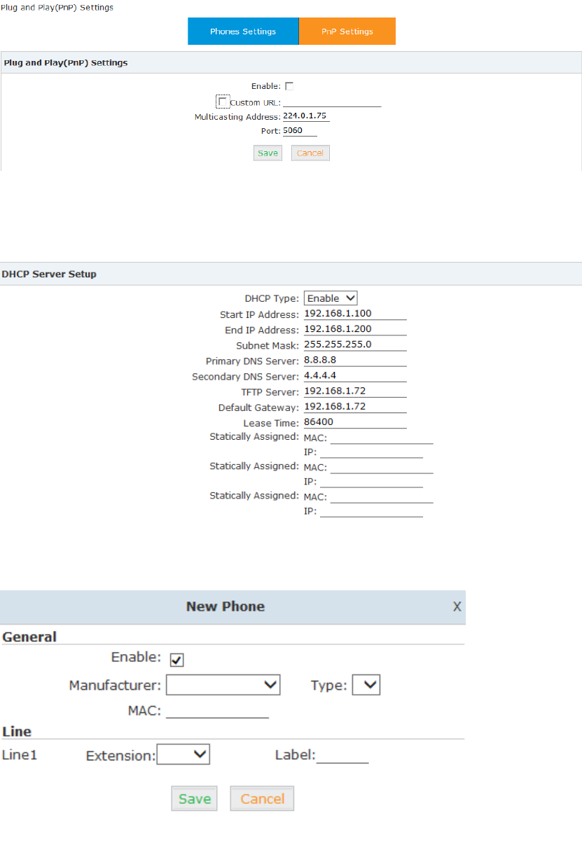
42
Method 1: PnP Settings
Select 【Advance】【Phone Provisioning】【PnP Settings】to enable PnP Settings, the default
will be shown as below:
Note: Custom URL is the path for some users to get the phone configuration files specially.
Method 2: Enable DHCP service
Click【Router Gateway】【Internet】【LAN】DHCP Server Setup in the following diagram:
Set the TFTP server and enable DHCP Server service.
Then Click【Advanced】【Phone Provisioning】【New Phone】:
Enable Phone Provisioning in【Basic】, select the IP Phone manufacture, input MAC of the phone,
and select the extension for provisioning.
43
Notice
UC510/520 supports phone provisioning with phone brands of Zycoo/Akuvox/Escene/Yealink/
Grandstream currently.
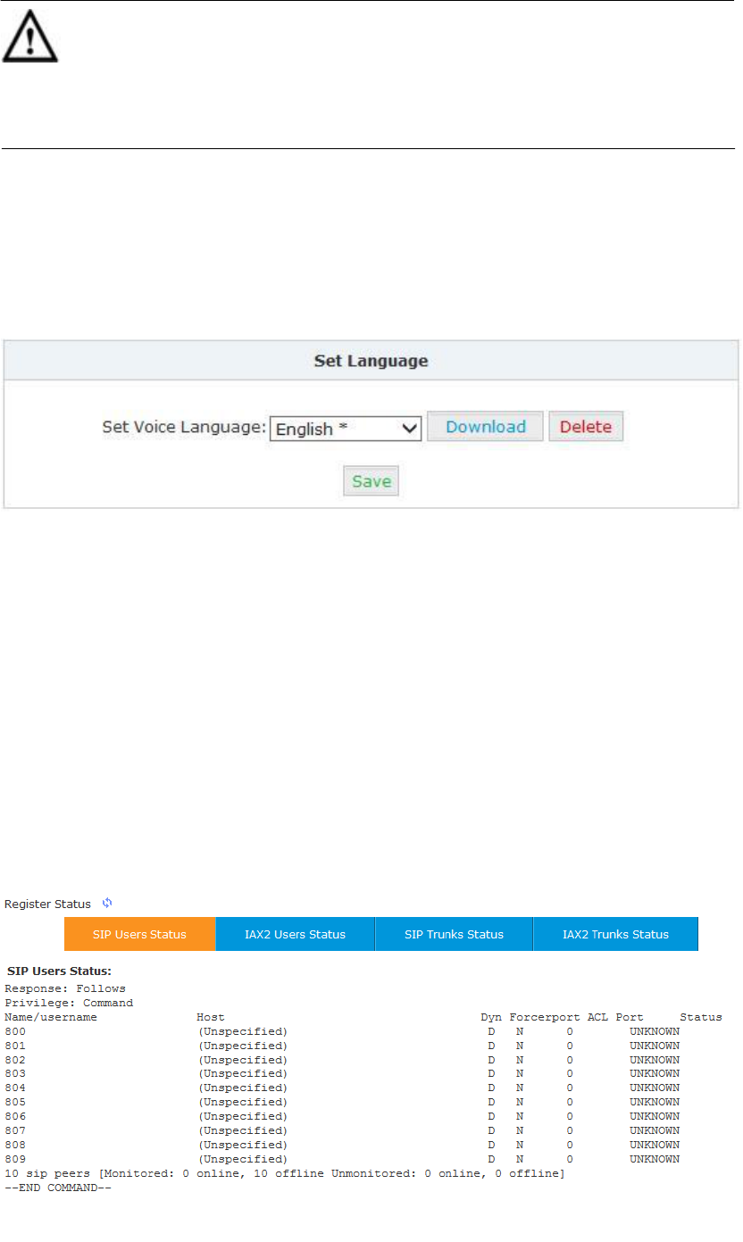
3.3.14 Set Voice Prompt Language
Voice prompt is the PBX system voice prompt, which is usually different for different countries.
Please select your countries official language as the system voice prompt language. If you can’t
find the language, you need to purchase the voice prompt from an independent supplier.
Click 【Advanced】【Set Voice Language】to set the system prompt language. It’s available
to download or delete the voice prompt package.
3.4 Report
3.4.1 Register Status
Register status is status report about the registered extensions.
Click【Report】【Register Status】to check status of the users and trunks.
44
Click【SIP Users Status】to show all SIP users status
Click【IAX2 Users Status】to show all IAX2 users status
Click【SIP Trunks Status】to show all SIP Trunks status
Click【IAX2 Trunks Status】to show all IAX2 Trunks status
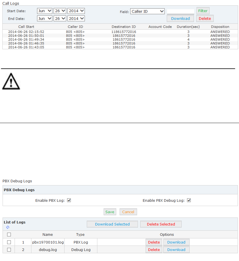
3.4.2 Call Logs
Check call logs by caller ID or callee ID.
Click【Report】【Call Logs】:
Notice
Duration in the call logs is not real charged duration. If you need billing, PSTN must support
polarity reversal function, and meanwhile, you must configure relevant parameters of polarity
reversal in trunk configuration for the UC510/520.
3.4.3 PBX Debug Logs
Click【Report】【System Logs】, you can download/ delete the system logs.
45
Chapter 4 Router Gateway
4.1 Internet
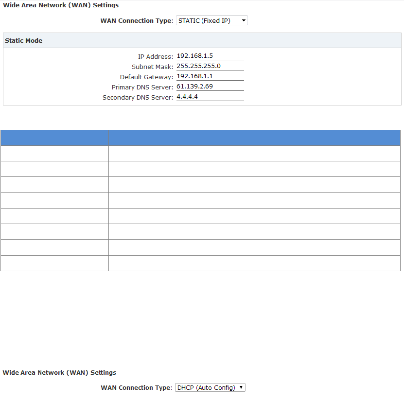
4.1.1 WAN
This page is used to configure the WAN port and clone the MAC address.
The device supports several methods for WAN port access including STATIC(Fixed IP)/ DHCP(Auto
Config)/ PPPoE(ADSL)/L2TP/PPTP; and UC520 supports LTE by default.
Static
Once you have selected Static, a static IP address provided by the network service provider needs
to be inserted. Subnet mask, default gateway and other relevant information must also be set.
Click【Internet】【WAN】:
WAN Connection Type: Select “STATIC(Fixed IP)”
Reference
Item
Explanation
WAN Connection Type
STATIC(Fixed IP)
IP Address
Set IP address, e.g.: 192.168.1.5
Subnet Mask
Set Subnet Mask, e.g.: 255.255.255.255
Default Gateway
Set default gateway, e.g.: 192.168.1.1
Primary DNS Server
Set the primary DNS server address
Secondary DNS Server
Set the secondary DNS server address
MAC Clone
Enable or Disable MAC Clone
MAC Address:
Cloned MAC address
DHCP
If DHCP is selected, the IP address, subnet mask and other relevant information will be obtained
from a DHCP server located on the network.
WAN Connection Type: Select “DHCP(Auto Config)”
46
PPPoE
If PPPoE is selected then the UC510/520 must be connected to the network via ADSL modem.
WAN Connection Type: Select “PPPoE(ADSL)”
Reference:
Item
Explanation
WAN Connection Type
PPPoE(ADSL)
User Name
Set the username
Password
Set the password
Verify Password
Verify the password
Operation Mode
Support three operation modes: Keep Alive/On Demand/Manual.
Keep Alive: when PPPoE is disconnected, system will redial PPPoE per
60s.
On Demand: No data from PPPoE to WAN, after lasting 5mins, PPPoE
will be disconnected automatically; when data is transported to
WAN, PPPoE will be re-connected automatically.
Manual: When PPPoE is disconnected, you have to click
“Save”---“Activate” manually, and PPPoE will redial.
L2TP
If L2TP is selected the UC510/520 will serve as a VPN client and therefore all traffic sent and
received will be encrypted, providing safe access to the business network by dialing to the
Internet Service Provider(ISP) or connecting to the internet or other network.
WAN Connection Type: Select L2TP
47
Reference:
Item
Explanation
WAN Connection Type
L2TP.
Server IP
Set the server IP
User Name
Set the user name
Password
Set the password
Address Mode
Support two modes: Static(Fixed IP)/ Dynamic(DHCP Auto Config)
IP Address
Set the IP address when Address Mode is Static
Subnet Mask
Set subnet mask when Address Mode is Static
Default Gateway
Set default gateway when Address Mode is Static
Operation Mode
Support two operation modes: Keep Alive/Manual.
Keep Alive: when L2TP is disconnected, system will connect again
every 60s.
Manual: When L2TP is disconnected, you have to connect
manually.
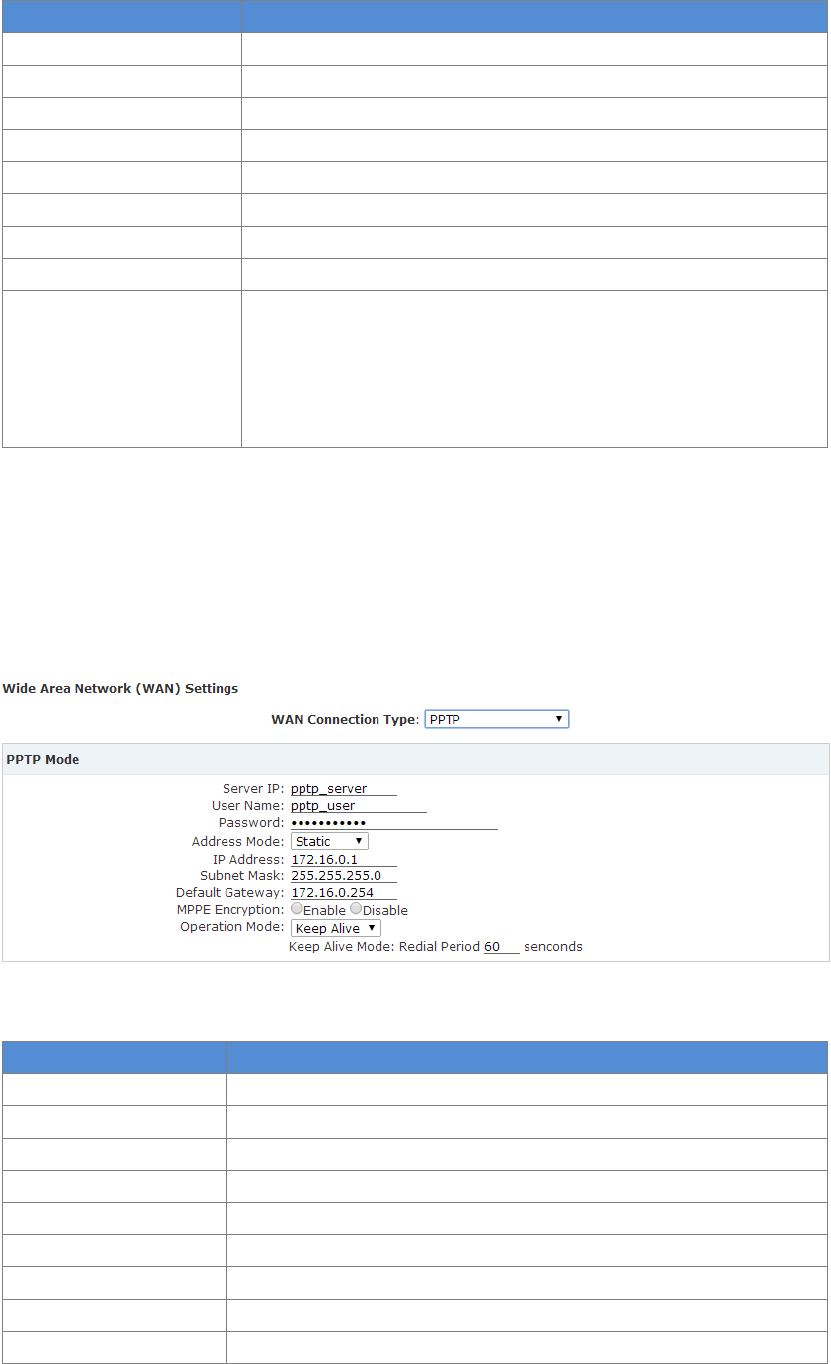
PPTP
If PPTP is selected the UC510/520 will serve as a VPN client and therefore all traffic sent and
received will be encrypted, providing safe access to the business network by dialing to the
Internet Service Provider(ISP) or connecting to the internet or other network.
WAN Connection Type: Select “PPTP”
Reference:
Item
Explanation
WAN Connection Type
PPTP
Server IP
Input server IP
User Name
Set user name
Password
Set password
Address Mode
Support two modes: Static(Fixed IP)/Dynamic (DHCP Auto Config)
IP Address
Set IP address when Address Mode is Static
Subnet Mask
Set subnet mask when Address Mode is Static
Default Gateway
Set default gateway when Address Mode is Static
MPPE Encryption
Enable or Disable MPPE Encryption (Microsoft Point-to-Point
48
Encryption)
Operation Mode
Support two operation modes: Keep Alive/Manual.
Keep Alive: when PPTP is disconnected, system will connect again
every 60s.
Manual: when PPTP is disconnected, you have to connect manually.
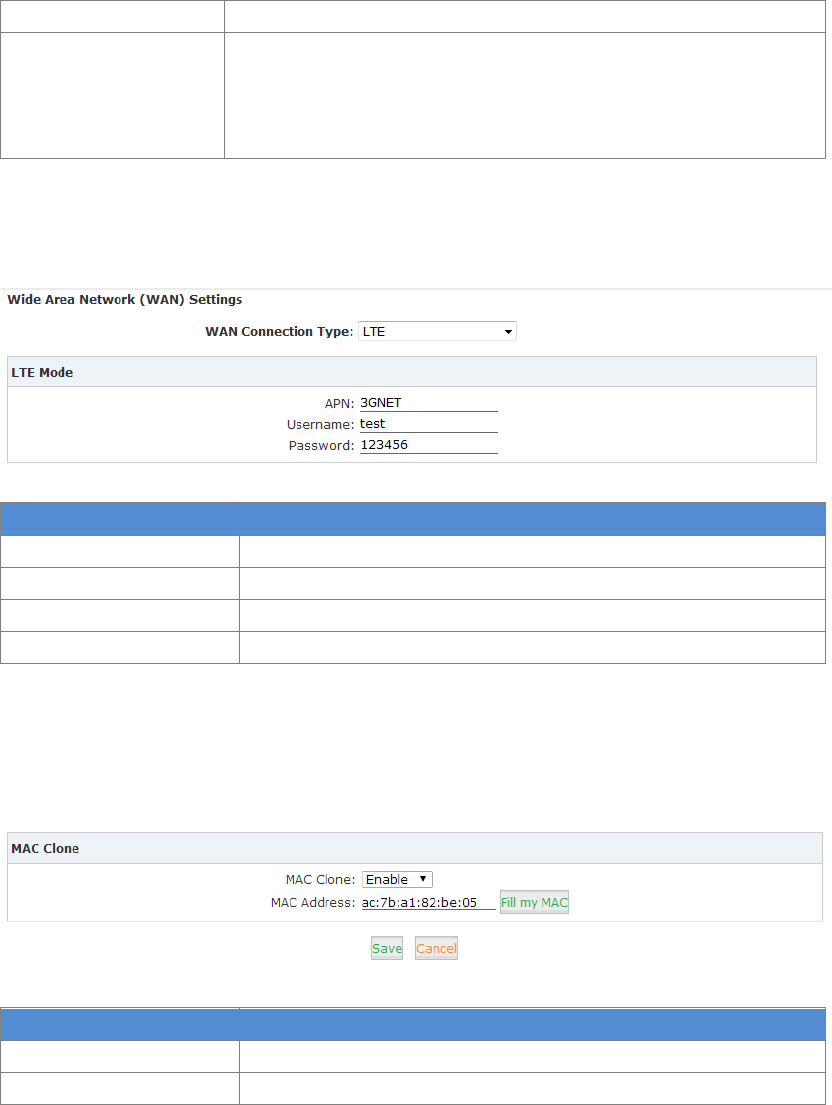
LTE
LTE network connection is supported on the UC520 only by default. It supports FDD-LTE.
WAN Connection Type: Select ”LTE”
Reference:
Item
Explanation
WAN Connection Type
Select LTE (Optional)
APN
Access Point Name, such as 3GNET. (mandatory field)
User Name
Set user name (Optional)
Password
Set Password (Optional)
MAC Clone
To prevent multiple users from sharing a broadband connection, the ISP will identify the MAC
address of the terminals.MAC Clone is used to clone the same MAC address of the WANport for
network connection. Multiple users can surf the internet through a single router.
Reference:
Item
Explanation
MAC Clone
Enable/Disable MAC Clone
MAC Address
Fill the cloned MAC address. E.g.: ac:7b:a1:82:be:05
4.1.2 LAN
LAN Setup
It’s necessary to configure the LAN IP for LAN based users to achieve internal network
connectivity.
Default LAN IP for UC510/520 is 192.168.1.1, and it can be changed as required.
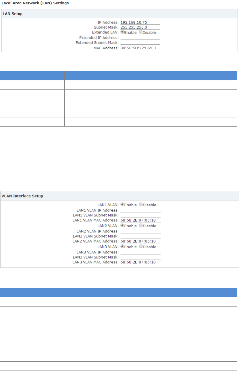
49
To make changes to the settings for the LAN port, VLAN and DHCP Server.
Click【Internet】【LAN】:
Reference
Item
Explanation
IP Address
Set LAN IP
Subnet Mask
Set subnet mask for LAN port
Extended LAN
Enable or disable Extended LAN
Extended IP Address
Set IP address for Extended
Extended Subnet Mask
Set subnet mask for Extended
VLAN Settings
VLAN provides the segmentation services traditionally provided only by routers in LAN
configurations. By using VLANs, one can control traffic patterns and react quickly to relocations.
VLAN provides the flexibility to adapt to changes in network requirements and allow for
simplified administration.
Reference
Item
Explanation
LAN1 VLAN
Enable or Disable VLAN of LAN1
LAN1 VLAN IP Address
Set the IP address of VLAN for LAN1
LAN1 VLAN Subnet Mask
Set the subnet mask of VLAN for LAN1
LAN1 VLAN MAC Address
Set the MAC address of VLAN for LAN1. You need to distribute a
new and independent MAC address which cannot be same as
the current system.
LAN2 VLAN
Enable or Disable VLAN of LAN2.
LAN2 VLAN IP Address
Set the IP address of VLAN for LAN2
LAN2 VLAN Subnet Mask
Set the subnet mask of VLAN for LAN2
50
LAN2 VLAN MAC Address
Set the MAC address of VLAN for LAN2. You need to distribute a
new and independent MAC address which cannot be same as
the current system.
LAN3 VLAN
Set the IP address of VLAN for LAN3
LAN3 VLAN IP Address
Set the subnet mask of VLAN for LAN3
LAN3 VLAN Subnet Mask
Set the MAC address of VLAN for LAN3
LAN3 VLAN MAC Address
Set the IP address of VLAN for LAN3. You need to distribute a
new and independent MAC address which cannot be same as
the current system.
Notice
VLAN IP address of LAN3/LAN2/LAN1 must be in different network segments;
MAC address must be different from LAN port; MAC address must be different during Port VLAN.
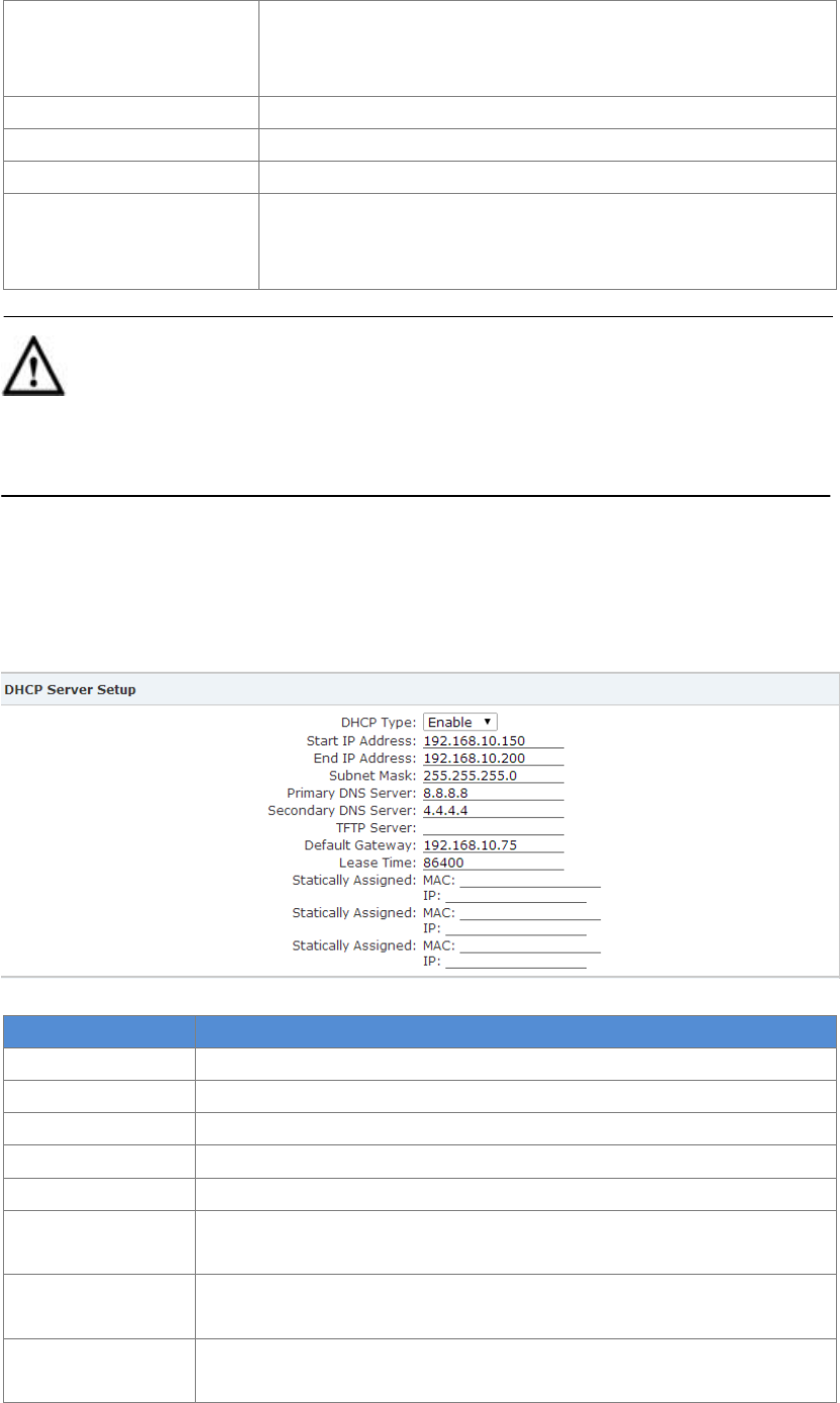
DHCP Server Setup
DHCP Server can used to automatically assign IP address to terminals accessing UC510/520.
Only the IP address range set here can be assigned automatically.
Reference:
Item
Explanation
DHCP Type
Enable or Disable DHCP
Start IP Address
Set Start IP address, which must be same as the LAN or Extended LAN
End IP Address
Set End IP address, which must be same as the LAN or Extended LAN
Subnet Mask
Set subnet mask address
Primary DNS Server
Set primary DNS sever address
Secondary DNS
Server
Set secondary DNS sever address
TFTP Server
Set TFTP server address, which supports OPTION66, and be used for IP
PBX Auto Provision
Default Gateway
Set default gateway address; it is recommended to be the LAN or
extended LAN IP address, otherwise, LAN user cannot surf internet.
51
Lease Time
Set the lease time of IP
Statically Assigned
Set statically assigned MAC and IP(at most 3). The client will receive the
corresponding IP address when DHCP is enabled.
Other Settings
Reference:
Item
Explanation
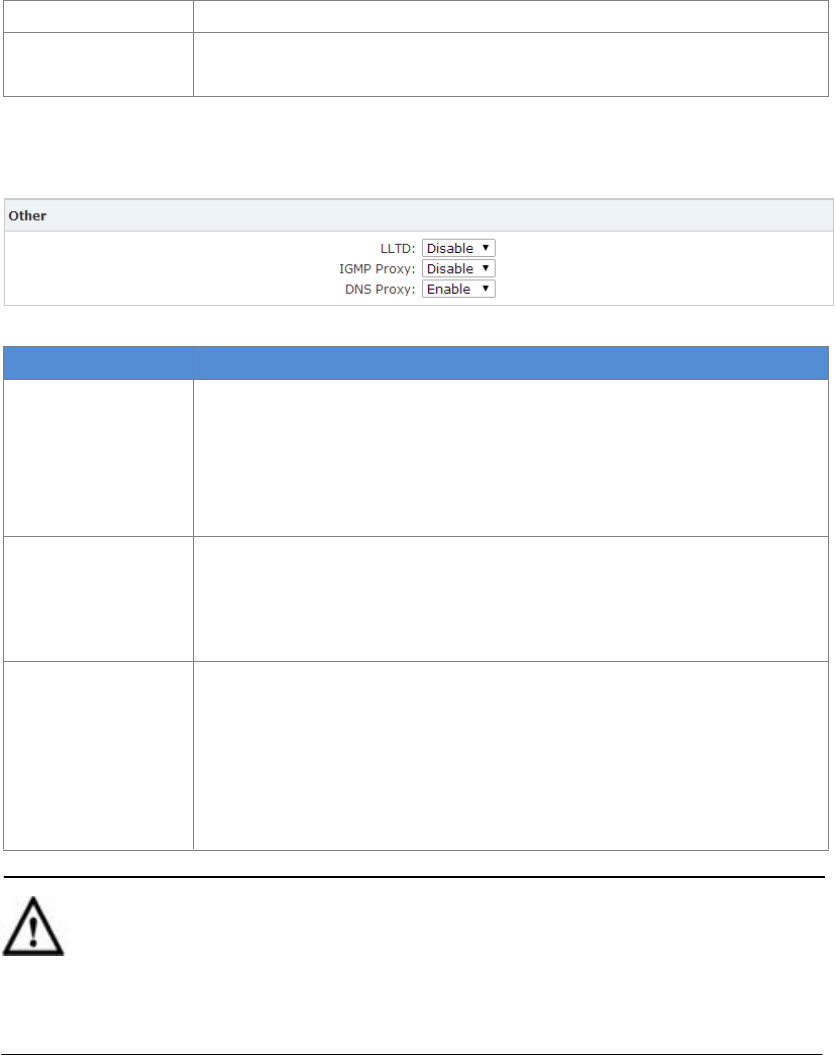
LLTD
LLTD(Link Layer Topology Discovery) is a proprietary Link Layer protocol
for network topology discovery and quality of service diagnostics; and
operates over both wired (such as Ethernet(IEEE802.3) or power line
communication as well as wireless networks (such as IEEE802.11) .
Default is disabled.
IGMP Proxy
IGMP(Internet Group Management Protocol)is a communications
protocol used by hosts and adjacent routers on IP networks to establish
multicast group memberships. IGMP is an integral part of IP multicast.
IGMP is one way of IGMP Proxy. Default is disabled.
DNS Proxy
DNS proxy server is used by companies to describe a DNS server that
directs clients to a proxy server for an unknown list of websites and
services. It is primarily used to unblock blocked content from websites
which contain region-restricted content. E.g.: When your client device
DNS is set as LAN IP of UC510, domains can be analyzed.
Default is enabled.
Notice
The DHCP server IP must be in the same segment as the LAN port, and the default gateway must
be the LAN IP, otherwise users will be unable to access the internet.
4.1.3 Static Routing
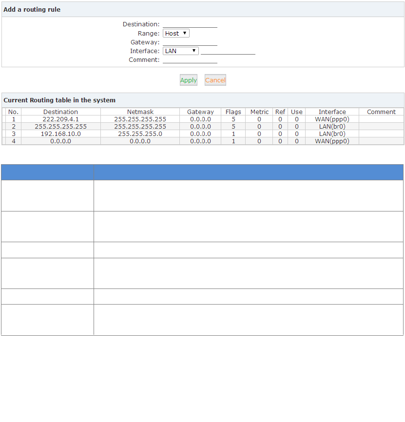
Static Routing is a form of routing that occurs when a router uses a manually-configured routing
entry, rather than information from a dynamic routing protocol to forward traffic.
Click【Internet】【Static Routing】:
52
Reference:
Item
Explanation
Destination
Set the IP address of destination host or network IP address. E.g.:
222.209.4.1, 192.168.10.0.
Range
Select the routing mode: Host or Net. When “Net” is selected, you need
to configure the netmask, e.g.: 255.255.255.0.
Gateway
Set the gateway address
Interface
Select the interface type: WAN/LAN/Custom. E.G.: Custom interface can
be eth2.3, eth2.4 or ppp2.
Comment
Name for this routing.
Current Routing
table in the system
Routing table list. The static routing created by yourself can be deleted,
but default routing cannot be deleted.
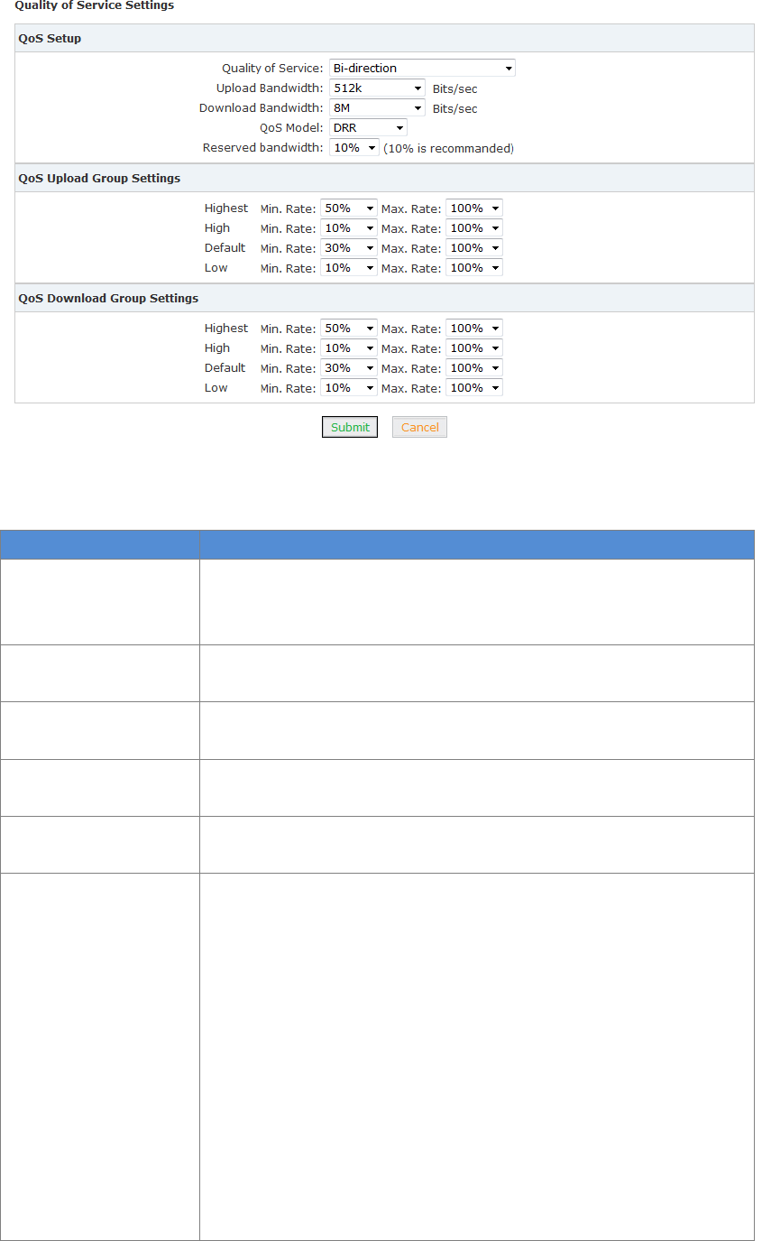
4.1.4 QoS
QoS(Quality of Service) is the overall performance of network, particularly the performance seen
by the users of the network. User can control the flow of WAN port traffic based on the QoS rule.
53
Click【Submit】, save the settings to automatically activate the upload or download flow control.
Reference:
Item
Explanation
Quality of Service
Select the QoS: Disable/ Bi-direction/Upload to Internet/Download
from Internet. Bi-direction include Upload to internet and Download
from internet
Upload Bandwidth
Define the upload bandwidth; it can be selected from the list or
custom defined
Download Bandwidth
Define the download bandwidth; it can be selected from the list or
custom defined
QoS Model
Support three models: DRR(Deficit Round Robin)/SPQ(Strict Priority
Queue)/DRR+SPQ. Default is DDR.
Reserved bandwidth
Reserve the bandwidth; It is recommended to reserve 10%. Default is
0%.
QoS Upload Group
Settings
Highest/High/Default/Low
Take the above as example:
Highest Min. Rate 50% Max. Rate 100%
High Min. Rate 10% Max. Rate 100%
Default Min. Rate 30% Max. Rate 100%
Low Min. Rate 10% Max. Rate 100%
If the bandwidth of upload/download is 10M, then the lowest
bandwidth for Highest group user is 5M, highest bandwidth can be
up to 10M
The lowest bandwidth for High group user is 1M, the highest
bandwidth can be up to 10M;
The lowest bandwidth for Default group user is 3M, the highest
bandwidth can be up to 10M;
54
The lowest bandwidth for Low group user is 1M, the highest
bandwidth can be up to 10M;
Total value of Min.Rate for the 4 groups from “Low” to “Highest”
must be less than 100% or equal to 100%.
If QoS is enabled then all client devices will comply with the “Default”
group.
Qos Download Group
Settings
The configuration of Qos Download Group Settings is same as Qos
Upload Group Settings as detailed in the example above.
After saving QoS settings, you can see “QoS Upload Group Settings” and “QoS Download Group
Settings” in【QoS】page.
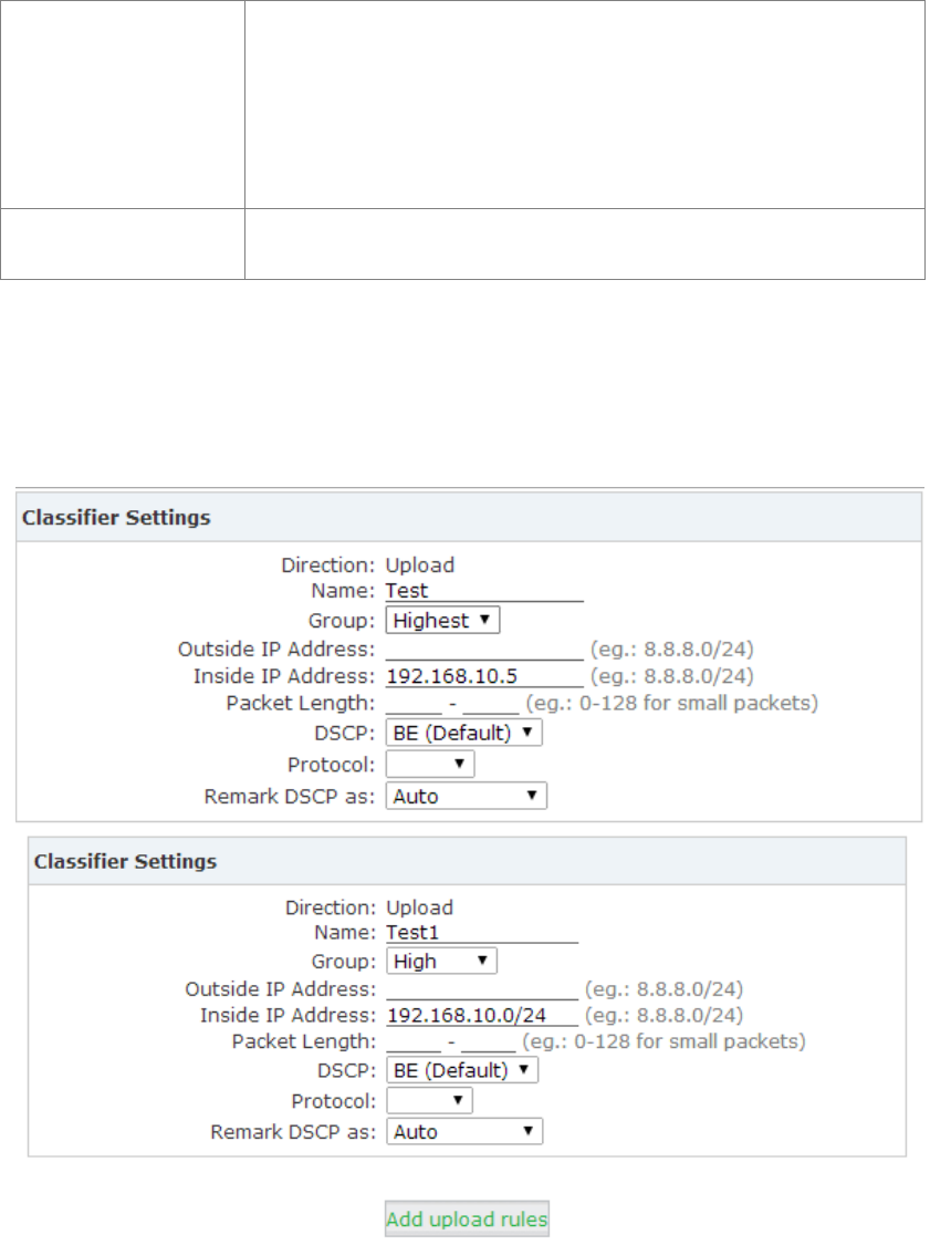
E.g.: Set the upload rate of a device whose IP is 192.168.10.5 to be Highest group, and other
device to be High group; set the download rate of intranet as the Highest group.
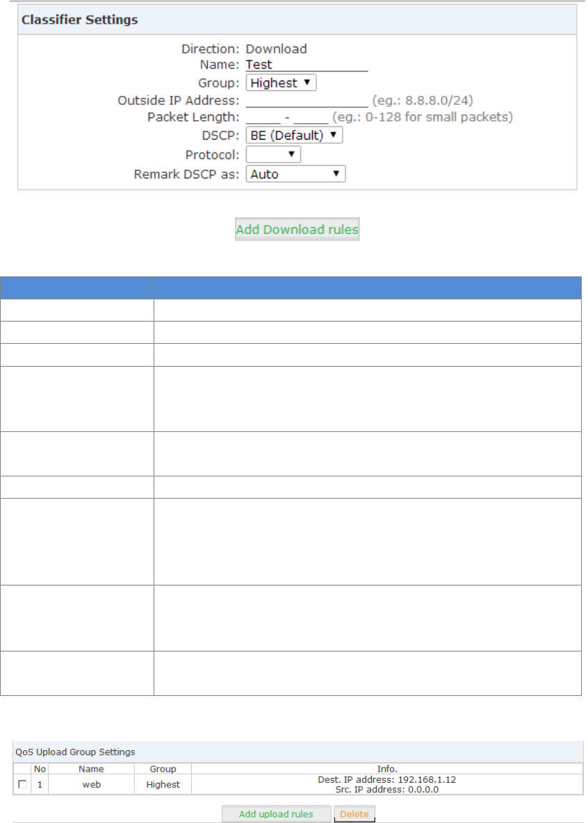
Click【Add upload rules】to enter the upload rule settings:
Click【Add download rules】to enter the download rule settings:
55
Reference:
Item
Explanation
Direction
Transmission direction (no need to configure)
Name
Custom define the rule name
Group
Select the corresponding group (or priority group)
Outside IP address
Set outside IP address(or network segment) and corresponding group
subnet mask digits, e.g.: 192.168.10.0/24. Or be null to allow all
outside IP address.
Inside IP address
Set inside IP address(or network segment) and subnet mask digits,
e.g.: 192.168.10.0/24. Or be null to allow all intranet IP.
Packet Length
Set the rule package length, or don’t set. Default is null.
DSCP
DSCP(Differential Service Code Point) supports: BE(default)/ AF11/
AF12/ AF13/ AF21/ AF22/ AF23/ AF31/ AF32/ AF33/ AF41/ AF42/
AF43/ EF
Default is null.
Protocol
You can select TCP/UDP/ICMP or null (all protocols use the default IP
address). When TCP or UDP is selected, you must complete the
outside and intranet port range.
Remark DSCP as
Optional. You can reset DSCP for QoS or do not change. Default is “Do
Not change”
Click【Add upload rules】to add the rule(at most 32 rules).
It is the same process to add download rule in “QoS Download Group Settings”.
Note: LAN IP 192.168.1.1 of the UC510 is not included in QoS settings. QoS settings is only for
client devices connected to LAN of UC510.
56
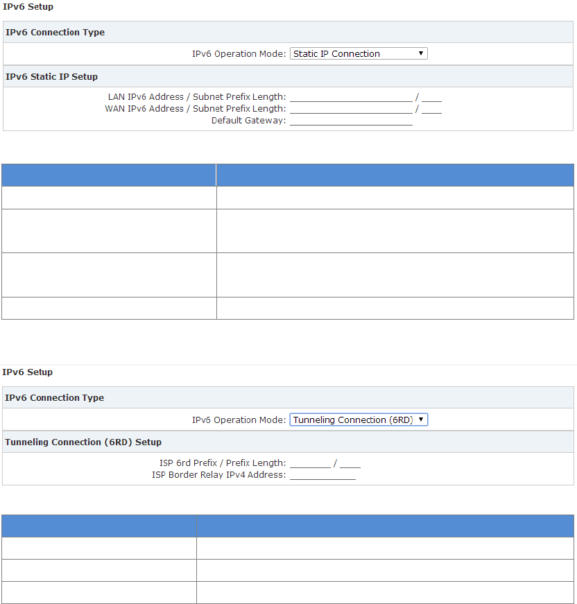
4.1.5 IPv6 Setup
Internet Protocol version 6 (IPv6) is the latest version of the Internet Protocol(IP), the
communications protocol that provides an identification and location system for IP based devices,
e.g. computer on networks and routes traffic across the Internet.IPv6 is intended to replace IPv4,
which still carries more than 96% of Internet traffic worldwide as of May 2014.
Click【Internet】【IPv6】:
Select Static IP Connection for IPv6 Operation Mode
Reference:
Item
Explanation
IPv6 Operation Mode
Static IP Connection
LAN IPv6 Address / Subnet Prefix
Length
Set IPV6 address and subnet prefix length on LAN
WAN IPv6 Address / Subnet
Prefix Length
Set IPV6 address and subnet prefix length on WAN
Default Gateway
Set default gateway
IPv6 Operation Mode: Select Tunneling Connection(6RD)
Reference:
Item
Explanation
IPv6 Operation Mode
Tunneling Connection(6RD):
ISP 6rd Prefix / Prefix Length
Set ISP 6RD prefix/prefix length
ISP Border Relay IPv4 Address
Set IPv4 address on Broadcast(Layer)
4.1.6 DHCP Client Info
The DHCP client info will displays the information of terminals once they have been assigned IP
address from DHCP server, including hostname, MAC address, IP address and expiration time.
Click【Internet】【DHCP Client Info】:
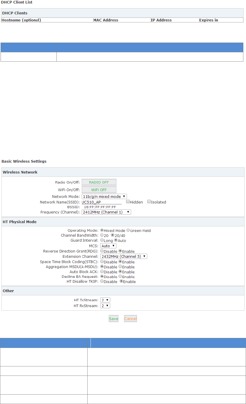
57
Reference:
Item
Explanation
DHCP Clients
Display all DHCP clients
4.2 Wireless
4.2.1 Basic
This option has some basic settings of wireless, such as wireless network, high throughput, entity
module and others.
Click【Router Gateway】【Wireless】【Basic】to show as below:
Reference:
Name
Introductions
Radio On/Off
RF(radio frequency) switch. Before enabling Wi-Fi, it must be
on. The default is On.
Wi-Fi On/Off
Wi-Fi switch
Network Mode
Alternative Wireless protocol, includes 11b/g/n mixed
mode, 11b only, 11g only and 11n only(2.4G)
Network Name(SSID)
SSID(Service Set Identification) also known as Wi-Fi name,

58
allows your wireless network to be easily distinguished from
other wireless networks. In addition, Hidden option can
make SSID invisible, nobody can search this Wi-Fi; Isolated
option is used for partitioning VLAN under the same SSID; in
other words, Isolated option users could not visit others
Host in the same SSID
BSSID
BSSID is Basic Service Set Identifier, which is defined as MAC
address of Wi-Fi router in IEEE 802.11.
Frequency (Channel)
Wi-Fi Frequency(Channel). It can be “AutoSelect” or selected
as a specific frequency. The default is “AutoSelect”
Operating Mode
Operation mode contains Mixed and Green Field.
Mixed Mode:wireless network card can identify Pre-N AP,
but throughput would be affected;
Green Field Mode:It will reach high throughput, but
compatibility and system security will be affected
The default is Mixed Mode
Channel Bandwidth
Supports 20MHz and 20MHZ/40MHz channel. In IEEE
802.11N mode, two 20MHZ channels can be bundled to a
40MHz channel; it can be used as two channels in real
working environment (one is primary, the other one is
secondary); this will double the transmission rate or
promote more.
The default is 20/40
Guard Interval
Is used to ensure that distinct transmissions do not interfere
with one another. These transmissions may belong to
different users (as in TDMA) or to the same user (as in
OFDM).
Send interval between the wireless signal; long interval or
auto interval is alternative
MCS
MCS(Modulation and Coding Scheme) is the wireless rate of
802.11n. Please select the index value of MCS; each value
corresponds to a communication rate determined by a set of
parameters.
The default is Auto.
Reverse Direction Grant(RDG)
Is used to guarantee the normal communication between
terminal and AP, especially in radio interference.
Extension Channel
If Frequency(Channel) is “AutoSelect”, then no extension
channels; If specific channel is selected, there will be
corresponding extension channel. And when Channel
Bandwidth is 20MHz, there will not be extension channel;
when Channel Bandwidth is 40MHz, there will be extension
channel, then the bandwidth will be promoted, as well as
transmission rate
Space Time Block Coding(STBC)
Space–time block coding is a technique used in wireless
59
communications to transmit multiple copies of a data
stream across a number of antennas and to exploit the
various received versions of the data to improve the
reliability of data-transfer.
Aggregation MSDU(A-MSDU)
A-MSDU(Aggregated MAC Service Data Unit) is a frame
aggregation mode, which is used to combine multiple
MSDUs into one MSDU for transmission. This will reduce the
amount of additional MAC head information in each MSDU
and improve the MAC-Layer transmission rate. The default is
enabled.
Auto Block ACK
Realize aggregate switch sequence and then increase
transmission rate. The default is enabled
Decline BA Request
Default is disable, in order to increase transmission rate
HT Disallow TKIP
Forbid TKIP encryption. The default is enabled.
HT TxStream
High throughput transmit data stream. Default value is 2.
HT RxStream
High throughput receive data stream. Default value is 2.
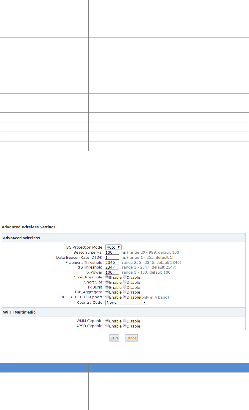
4.2.2 Advanced
The wireless advanced setting includes advanced wireless and Wi-Fi multimedia (WMM)
configurations.
Click【Router Gateway】【Wireless】【Advanced】to show as below:
Reference:
Name
Instruction
BG Protection Mode
BG = IEEE802.11b/g
It benefits for improving slower wireless connection access
to router by complex multiple mode.
The default is Auto

60
Beacon Interval
Beacons are packets sent by a wireless Access Point to
synchronize wireless devices. Beacon Interval is the time
between beacon transmissions. The access speed of the
wireless client will be higher when the interval value is
lower.
The default is 100ms.
Data Beacon Rate (DTIM)
A DTIM is a countdown informing clients of the next window
for listening to broadcast and multicast messages.
The default is 1ms.
Fragment Threshold
Specifies the fragmentation threshold for data packets,
when the packet length exceeds fragmentation threshold, it
will be divided into various data packets automatically. More
data packets will result in poor performance of the network.
It’s not recommended to set a lower value.
The default is 2346.
RTS Threshold
Specify the RTS threshold for data packets, when the packet
length exceeds this value, the router will send the RTS to
destination for negotiate, after receiving the RTS frame,
wireless site will respond to a CTS (Clear to send) frame in
response to the router and the client; which means there is
wireless communication between them.
TX Power
Define the size of current wireless AP for SSID transmitted
power, the larger the signal stronger. The default is 100.
Short Preamble
Enable short preamble to make the network synchronization
performance better. The default is enabled.
Short Slot
Enable it to improve the transmission efficiency of wireless
communication. The default is enabled.
Tx Burst
Enable it to assure the AP has a higher throughput without
changing the network environment and increasing the
transmission duration. Default is enabled.
Pkt_Aggregate
Packet Aggregate. Enable it to strengthen the mechanism of
local area network to ensure correct packet to the
destination
IEEE 802.11H Support
Extension of the 5 GHZ microwave standard of physical layer
and MAC sub-layer (mainly used in Europe)It solves
problems like interference with satellites and radar using the
same 5 GHz frequency band.
Country Code
Choose your country code in the drop-down list
WMM Capable
Enable it to improve wireless multimedia data transmission
performance (such as video or online broadcast). If you are
not familiar with the WMM, please set it to capable.
APSD Capable
Automatic Power Save Delivery. Enable it to save power
when no data is transmitted. This may affect the wireless
network performance. Default is disabled.
61
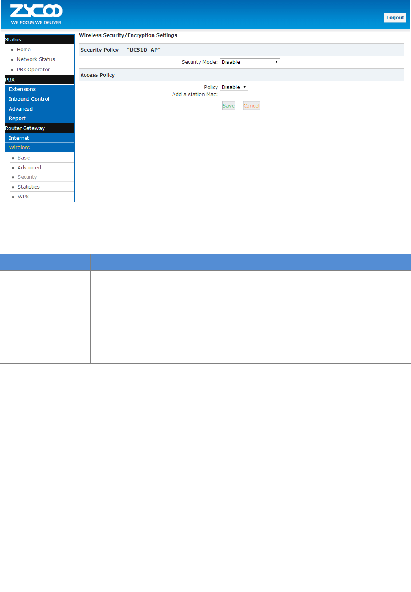
4.2.3 Security
The security page allow for configuration of wireless network security/ encryption settings.
Click【Router Gateway】【Wireless】【Security】to show as below:
Reference:
Item
Explanation
Policy
Select Disabled, Allow, Reject in the drop-down list
Add a station Mac
Here you can add a new MAC address for a Frequency Wi-Fi client .If
Disabled is selected then the access policy is disabled; If Allow is selected
then the MAC access is allowed only to access; If Reject is selected then
all the MAC addresses listed here will be rejected.
You are allowed to add 64 MAC addresses maximum.
Wireless network security/encryption Settings include: security policy and access policy. Security
policy includes 4 modes: OPENWEP, WPA2-PSK, WPA-PSK/WPA2-PSK, WPA1/WPA2.
WEP: Wired Equivalent Privacy, which is a security algorithm for IEEE 802.11 wireless networks.
WEP uses the stream cipher RC4 for confidentiality, and the CRC-32 checksum for integrity.
OPENWEP is one way of WEP.
WPA: Wi-Fi Protected Access, which is a security protocol and security certification program
developed by the Wi-Fi Alliance to secure wireless computer networks.
WPA2: Wi-Fi Protected Access II, known as IEEE 802.11i-2004, is the successor of WPA .
WPA-PSK: Wi-Fi Protected Access Pre-shared Key, also referred to WPA-Personal. It’s designed for
home and small office networks and doesn’t require an authentication server.
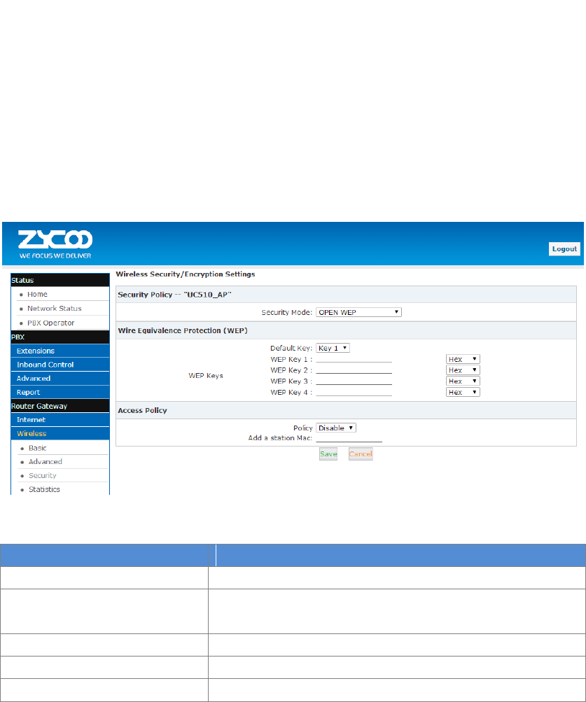
62
WPA/WPA2: is mainly used for enterprise. Adopt 802.1x for authentication and generating root
key for encryption data, but not set PSK(pre-shared key) manually. RADIUS server replaced the
single password mechanism in authentication.
When WPS is enabled, users can use 4 security encryption modes: OPENWEP, WPA-PSK,
WPA2-PSK and WPA-PSK/WPA2-PSK. Here let’s introduce the 4 modes in detail, but WPA2-PSK is
recommended.
OPENWEP
Click【Router Gateway】【Wireless】【Security】, Select【Security Mode】as OPENWEP:
Reference:
Item
Description
Security Mode
OPENWEP
Default Key
Select one of the WEP key as default key, and define the four
keys. User can access wireless AP with one of four keys.
WEP Key
User can set 4 keys here.
Hex
Hex is hexadecimal
ASCII
ASCII is binary
WPA-PSK
click【Router Gateway】【Wireless】【Security】, select【Security Mode】WPA-PSK to show
below:
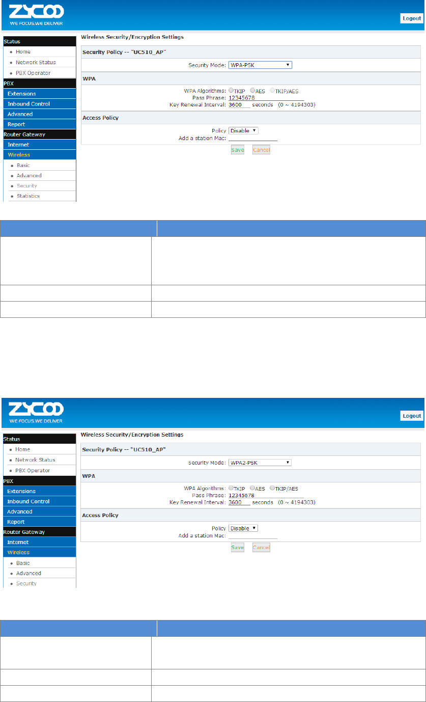
63
Reference:
Item
Explanation
WPA Algorithms
Support TKIP(Temporal Key Integrity Protocol) and AES
(Advanced encryption standard). User can select one
algorithm.
Pass Phrase
Input Wi-Fi password, e.g.: @Ab2-Cw158
Key Renewal Interval
The key update interval defaults to 3600 seconds
WPA2-PSK
Click【Router Gateway】【Wireless】【Security】, select【Security Mode】WPA2-PSK to
show below:
WPA2-PSK parameter table:
Item
Description
WPA Algorithms
Support TKIP and AES, TKIP/AES. User can select one of
three encryption algorithms.
Pass Phrase
Input Wi-Fi password
Key Renewal Interval
The key update interval defaults to 3600 seconds
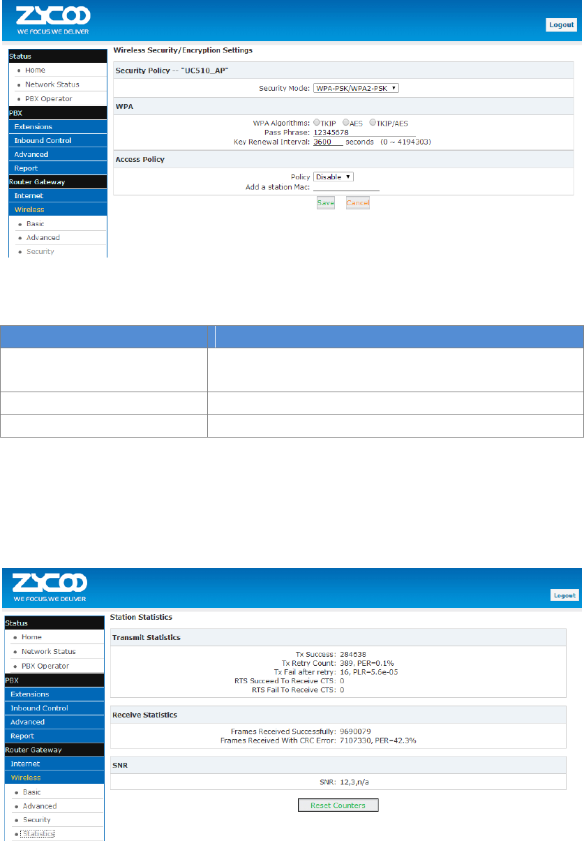
64
WPA-PSK/WPA2-PSK
click 【Router Gateway 】【Wireless 】【Security 】, then select 【Security Mode 】
WPA-PSK/WPA2-PSKto show as below:
Reference:
Item
Description
WPA Algorithms
Support TKIP and AES, TKIP/AES. User can select one of
three encryption algorithms.
Pass Phrase
Input Wi-Fi password
Key Renewal Interval
The key update interval defaults to 3600 seconds
4.2.4 Statistics
Wireless transmit/receive status statistics, click【Router Gateway】【Wireless】【Statistics】
to show as below:
Statistical parameter table:

65
Item
Description
Tx Success
Successful transmission package size (by byte)
Tx Retry Count
Transmission retry count (by byte); PER (Percent Ratio)
count by percentage.
Tx Fail after retry
Statistics of Retry after transmission failure(by byte); PLR :
Packet Loss Rate
RTS Succeed To Receive CTS
Received CTS successfully after sending RTS
(RTS/CTS refer to Request to Send and Clear to Send, flow
control signal)
RTS Fail To Receive CTS
Failed to receive CTS after sending RTS
(RTS/CTS refer to Request to Send and Clear to Send, flow
control signal)
Frames Received Successfully
Receive frames successfully (by byte)
Frames Received With CRC Error
Received the frame CRC errors, in bytes, PER as a percentage
SNR
Signal-to-Noise Ratio is defined as the power ratio between
a signal(meaningful information) and the background
noise(unwanted signal). The greater the SNR, the smaller
the noise power is.
WPS
WPS (Wi-Fi Protected Setup) was launched by the Wi-Fi alliance as a new Wi-Fi security setting,
mainly in order to solve the long wireless encryption authentication set. The drawbacks of the
steps is that it is too complex, difficult, WPS function on the wireless router can let's take a quick
easy encryption wireless network data transmission, to prevent the invasion of illegal users.
Traditionally, a Wi-Fi router limits illegal access by assigning a complicated password. This makes
it inconvenient to both memorize and input the password. WPS provides a much easier and
relatively more secure way of limiting illegal access and attack.
There are two ways to configure WPS. Let’s take the mobile phone as example:
1. If you enabled WPS on your mobile phone, then press the turbo button on the UC510, the
UC510 will automatically authorize your phone to access Wi-Fi. Of course, only company staff
who are in the office can press the turbo button.
2. You can generate a random password from the UC510 GUI, and you can input the password on
your mobile phone to access Wi-Fi.
Click【Router Gateway】【Wireless】【WPS】to show as below:
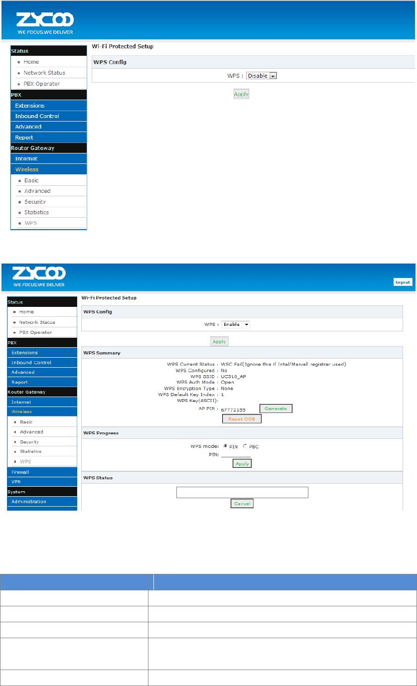
66
Default is disabled. Select Enable for startup, as shown below:
Note: Click “Reset OOB” to reset all the Wi-Fi settings, and all the information will be generated
automatically.
WPS Reference:
Item
Description
WPS Current Status
WPS Current Status. Idle=Inactive
WPS Configured
Yes: WPS is configured
WPS SSID
SSID, can be set in the Basic screen Network Name (SSID)
WPS Auth Mode
WPS Authentication Mode; a kind of security mode, same as
the “Security” menu.
WPS Encryption Type
WPS Encryption Type
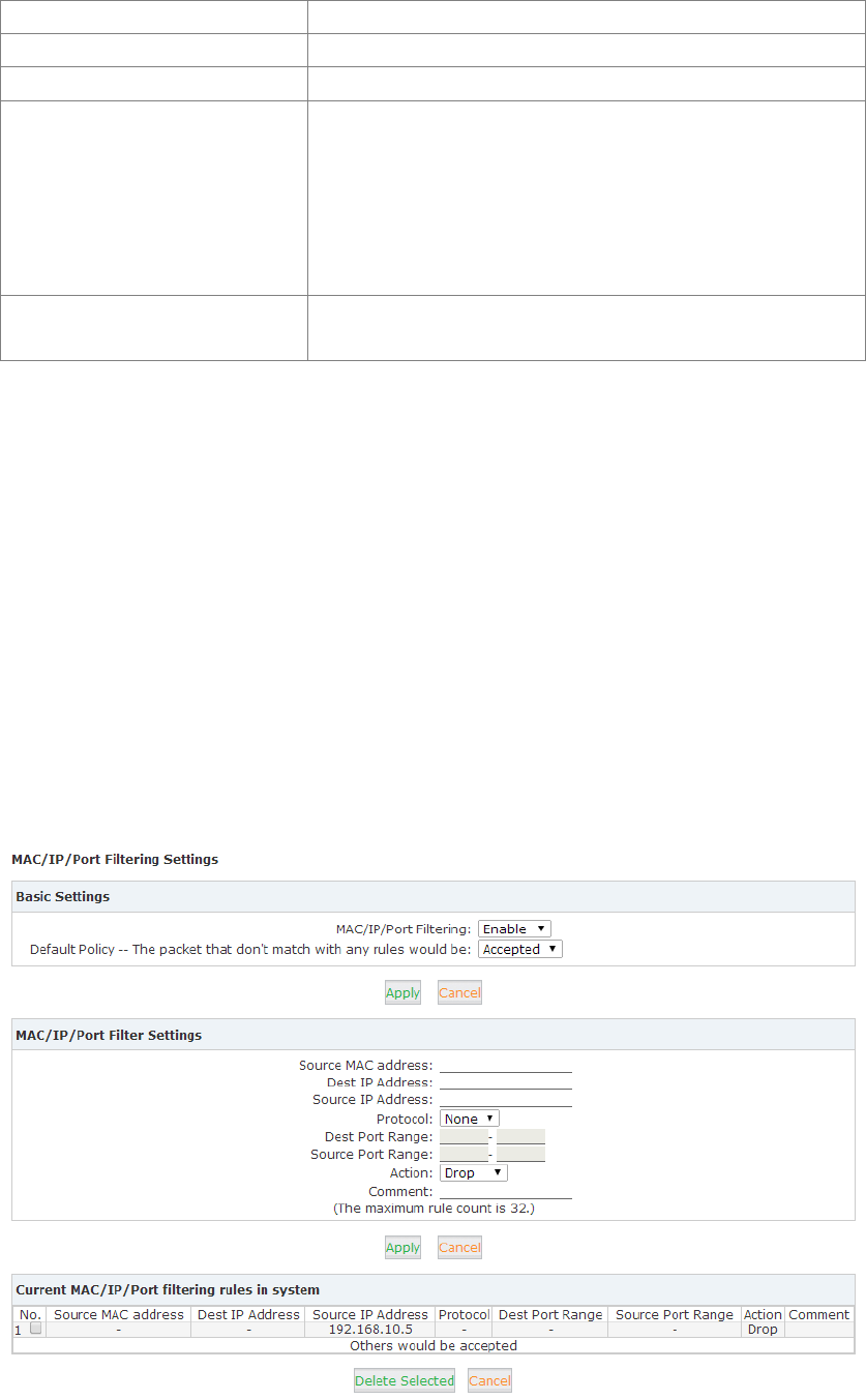
67
WPS Default Key Index
Default key index of WPS
WPS Key(ASCII)
Wi-Fi password
AP PIN
PIN code for wireless clients to connect to AP via WPS
WPS mode
Support PIN(Personal Identification Number) and PBC(Push
Button Configuration)
PIN: Click “Apply” after inputting PIN.WPS Current Status will
display the connection is successful after WPS is connected;
PBC: Click “Apply” after selecting PBC, or quickly click the
Turbo button on the router, wireless clients can connect.
WPS Status
Status about wireless clients connect to the WPS, which is in
accordance with WPS Current Status.
4.3 Firewall
4.3.1 MAC/IP/Port Filter
Any connection request from terminals can be controlled by the filter feature according to the
defined rule parameters. Filtering based on MAC, source IP and source port can prevent the
terminal from unauthorized network connections.
Set MAC/IP/Port filter:
Click【Firewall】【MAC/IP/Port Filter】: take the following diagram as example, the host with
192.168.10.0/24 is allowed to surf internet, but the host with 192.168.10.5 is rejected to connect
network.

68
Reference:
Item
Explanation
MAC/IP/Port Filter
Enable/Disable the MAC/IP/Port filter
Default Policy
The default strategy, set up to receive or discard the
specified Mac/IP/Port of packets
Source MAC Address
Set the source host MAC address, e.g.: 00:12:0f:dd:22:01
or null
Dest. IP Address
Set the destination host IP address, such as
221.220.215.0/24 or 192.188.10.12/32 or 192.188.10.12
Source IP Address
Set the source host IP address, such as 192.168.10.0/24or
192.168.10.12/32 or 192.168.10.12
Protocol
Set the protocol type. None means all types
Dest. Port Range
Set the destination port range
Source Port Range
Set the source port range
Action
Set the action: Accept or Drop
Comment
Annotation
Basic Settings
Click【Apply】and save settings
MAC/IP/Port Filter Settings
Click【Apply】and save settings. The maximum rule count is 32.
Current MAC/IP/Port filtering rules in system
Current MAC/IP/ Port filtering rules in the system are listed here. Click【Delete Selected】 to
delete selected rule.
Activate Notice
Click【Active】to activate configuration
Notice
If you are not familiar with Firewall settings, please DO NOT add rules here by yourself in case of
any failure on the system. If you are not familiar with the port of application program, please DO
NOT set “Default Policy” as “Dropped” in Basic Settings.
4.3.2 System Firewall
System Firewall is used to strengthen the security of the system and protect connected endpoint
devices and the PBX from malicious attacked.
System Firewall Settings
Click【Firewall】【System Firewall】
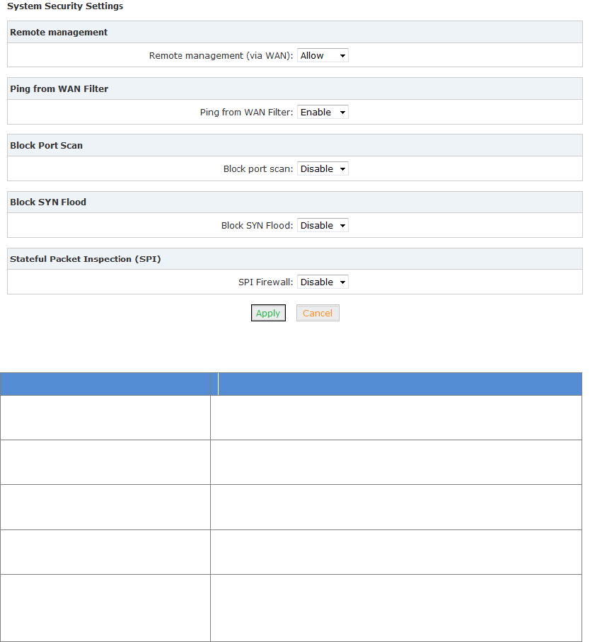
69
Reference
Item
Explanation
Remote management
Allow/ Deny: Remote access web GUI and SSH through
WAN port. The default is Deny.
Ping form WAN Filter
Enable/ Disable: Filter the WAN port in/out ping packet.
Default is disabled, namely allow ping.
Block Port Scan
Enable/ Disable: Blocking the WAN port scan. Default is
enabled.
Block YSN Flood
Enable/ Disable: Prevent the SYN Flood attack. Default is
enabled.
Stateful Packet Inspection(SPI)
Enable/ Disable the process used by a firewall to keep
track of the state of network connections. It’s the highest
level security. Default is enabled.
4.3.3 Port Forward
Port forward allows remote computers (for example, computers on the Internet) to connect to a
specific computer or service within a private local-area network (LAN).
Packet Forwarding Settings:
Click【Firewall】【Port Forward】: from the following diagram, visit port 222 from WAN, the data
will be forwarded to the client 192.168.10.5.
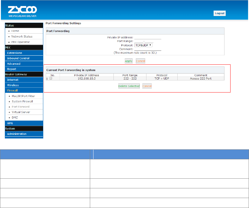
70
Reference:
Item
Explanation
Private IP Address
Private destination IP address that packet forwarded to.
E.g.: 192.168.10.5
Port Range
Destination port range that packet forwarded. E.g.: 222
Protocol
TCP&UDP/TCP/UDP
Comment
Annotation for this port forwarding
Port Forwarding
Click【Apply】and save settings. Basic information configuration(Max.32 port forwarding rules).
Current Port Forwarding in system
Current Port Forwarding in the system is listed here. Click【Delete Selected】to delete selected
rule.
Activate Notice
Click【Active】to activate configuration.
4.3.4 Virtual Server
Virtual Server is used to map the port range between WAN and LAN terminals of UC510/520.
The access of WAN to the port range will be directed to the specified terminals on the LAN. This
feature is particularly useful for remote working.
Virtual Server Settings:
Click【Firewall】【Virtual Server】: take the following diagram as example, visit port 2222 from
WAN, the data will be forwarded to the port22 of client 192.168.10.5.
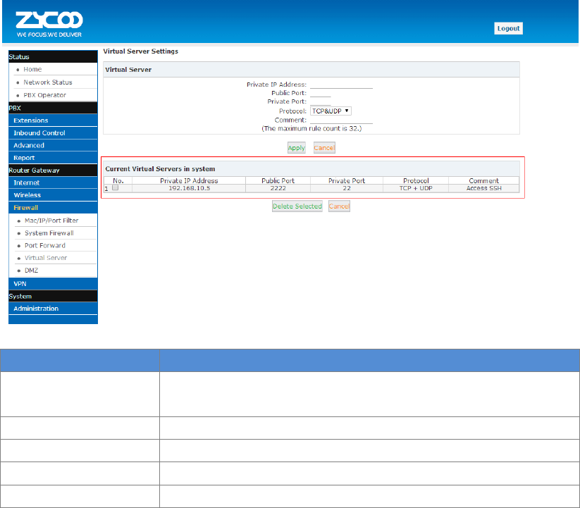
71
Reference:
Item
Description
Private IP Address
Private destination IP address that packet forwarded to.
E.g.: 192.168.10.5
Public Port
Public port that packet visited
Private Port
Internal port that packet forwarded
Protocol
TCP
Comment
Annotation
Virtual Server
Basic information configuration(Max. 32Virtual Server)
Current Virtual Server in system
Current virtual server in system is listed here. Click【Delete Selected】to delete selected virtual
server.
4.3.5 DMZ
DMZ is used to allow a personal computer connected to LAN to be exposed to the internet.
DMZ Settings
Click【Firewall】【DMZ】: from the following diagram, the data visited from all ports via WAN
will be forwarded to the port of client 192.168.10.5.
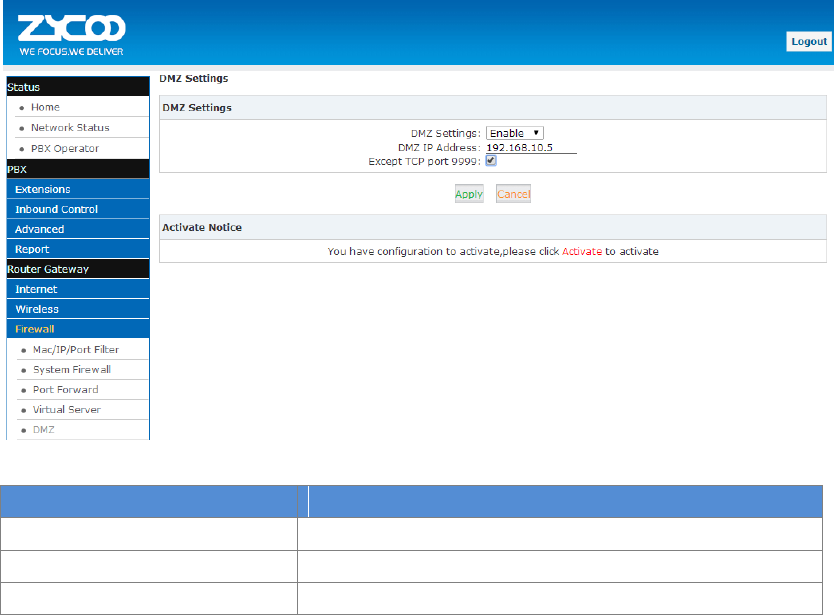
72
Reference:
Item
Description
DMZ Setting
Enable/ Disable the DMZ function
DMZ IP Address
DMZ host IP address
Except TCP port 9999
Tick to open TCP port 9999(http)
Activate Notice
Click【Activate】to activate configurations.
4.4 VPN
4.4.1 VPN Server
VPN(Virtual Private Network) is a way of connecting a computer to a remote network in a secure
manner to ensure traffic between the computer and remote network is encrypted. Most people
using computers connect to the worldwide web using a normal network - they use dial-up or
broadband. It's used by some worker to connect using a laptop to do work - they can check their
work email and see work websites which cannot be seen on the normal internet.
CooVox IP PBX supports two kinds of VPN servers: L2TP/PPTP. (Max. 10 VPN clients are available
to connect.)
Click【Router Gateway】【VPN】【VPN Server】, enable “L2TP” as the following diagram:
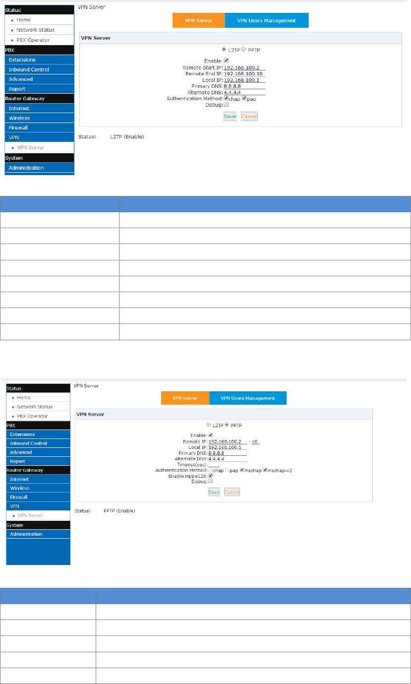
73
Reference
Item
Explanation
Enable
Enable/Disable L2TP or PPTP
Remote Start IP
Remote Start IP distributed to client by L2TP
Remote End IP
Remote End IP distributed to client by L2TP
Local IP
Local IP
Primary DNS
Primary DNS
Alternate DNS
Alternative DNS
Authentication Method
chap/pap
Debug
Open/Close debug of logs
Enable PPTP as the following diagram:
Reference:
Item
Explanation
Enable
Enable/Disable L2TP or PPTP
Remote Start IP
Remote Start IP distributed to client by L2TP
Remote End IP
Remote End IP distributed to client by L2TP
Local IP
Local IP
Primary DNS
Primary DNS
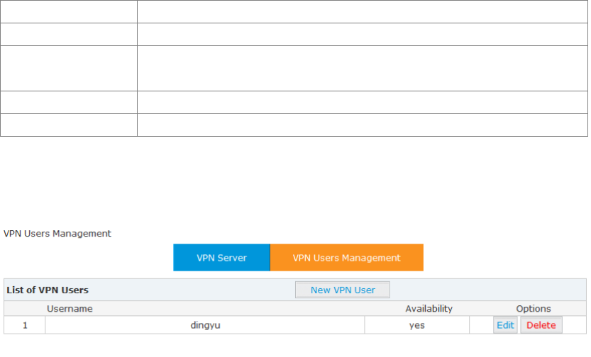
74
Alternate DNS
Alternative DNS
Time out (sec)
Time out for connection (Default is 120s)
Authentication
Method
support chap/pap/mschap/mschap-v2 authentication encryption
algorithm
Enable mppe123
Microsoft encryption algorithm; it’s recommended to be enabled
Debug
Open/Close debug of logs
After configuring VPN server settings, please create VPN client’s username and password, as well
as username and password of L2TP/PPTP.
Click【Router Gateway】【VPN】【VPN Server】【VPN Users Management】:
This page is used for management of VPN username and password.
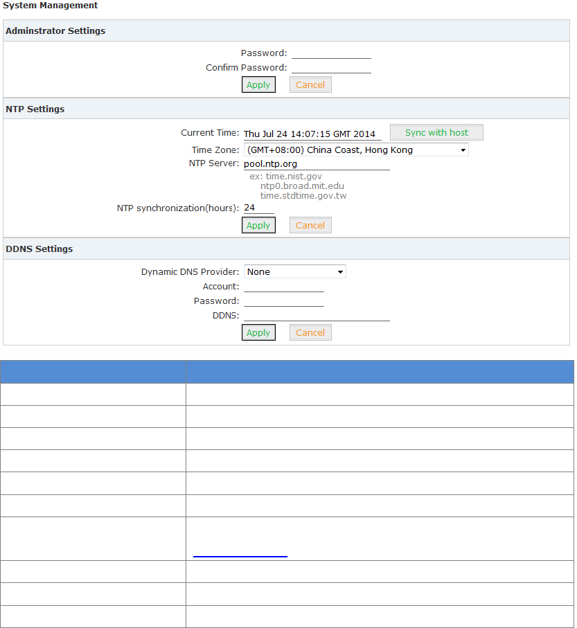
75
Chapter 5 System
5.1 Administration
5.1.1 Management
The purpose of the management page is to configure settings for administrator passwords, NTP
service, DDNS service.
Click【Administration】【Management】to configure:
Item
Explanation
Password
Input new password
Confirm Password
Confirm the new password
Current Time
Synchronize the current time
Time Zone
Select your time zone
NTP Server
Input the NTP server to synchronize the time
NTP synchronization (Hours)
The interval of NTP synchronization. Default is 24 hours
Dynamic DNS Provider
Support Dyndns.org / freedns.afraid.org/ www.zoneedit.com /
www.no-ip.com
Account
Input the account which is applied from DNS provider
Password
Input the password which is applied from DNS provider
DDNS
Input the host which is applied from DNS provider
After settings, click "Apply" to activate.
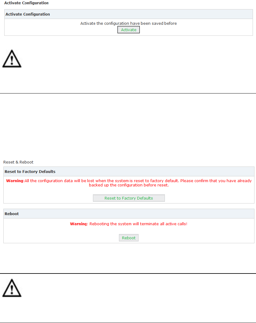
76
5.1.2 Activate Configuration
Activate Configuration is only for Wi-Fi router here. PBX settings is separate and not included
here.
There are two ways to activate configurations:
a) After settings for a function of router, press “Activate” at the bottom of the relative page to
activate the settings;
b) Click 【Administration】【Activate Configuration】 to enter the page as below:
Notice:
During this activation period, network will restart and disconnect in a short time; please prepare
before this operation.
5.1.3 Reset &Reboot
Reset will make the system reset to factory settings, and reboot will make the system restart.
Click【Administration】【Reset & Reboot】to show the page as below:
Click "Factory Defaults" to reset the system to the Factory settings; click "Reboot" to restart the
system.
Notice:
All network will be disconnected when system reboots and all the business will be interrupted. All
the functionalities are not available in a short time; please prepare before operation.
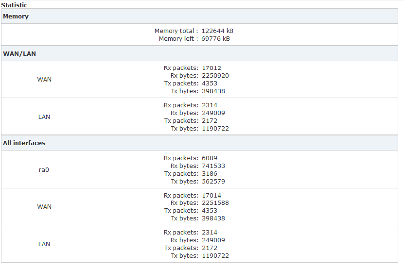
77
5.1.4 Statistics
You can check the system operation condition from【Statistics】, including memory usage,
network contract, quantity of packages, etc..
Click【Administration】【Statistics】to take a view:
Remark:
ra0: Wi-Fi interface
LAN: includes LAN1 ~LAN4 by default
5.1.5 Upgrade
Upgrade is used to update your system as required.
The system can be upgraded from this【Upgrade】page via uploading package.
Click【Administration】【Upgrade】:
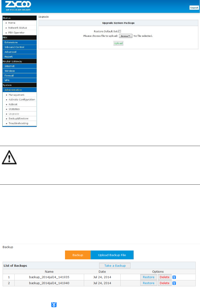
78
Select the upgrade file and then click the "Upload" button, the system will be automatically
upgraded.
Notice:
All functions will not be available during system upgrade; please prepare before operation.
Please do not change the updated file in case of any failure of the upgrade.
5.1.6 Backup&Restore
The system settings including IVR prompt, music files on hold, and Wi-Fi router configurations can
be backed up in case of any failure of the system. Within the backup files, you can easily restore
the system.
Click【Administration】【Backup&Restore】:
Click the “Take a Backup” button to back up the settings, and you will find the backup file’s name
and date. You can click to download the backup file and save it to your computer; when you
need to recovery the settings, you can upload it from "Upload Backup File", or click the “Restore”
button of the relative backup file to recovery the settings
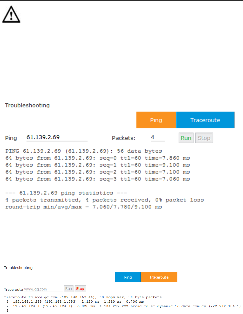
79
Notice:
All functions will not be available during backup & restore; please prepare before operation.
Please do not change the backup files in case of any failure of backup or restore.
5.1.7 Troubleshooting
Troubleshooting is used for network connection test.
Click【Administration】【Troubleshooting】【Ping】to test:
Input the destination address and contract number, then click "Run" to wait for the results.
Test route:
Click【Administration】【Troubleshooting】【Traceroute】to test:
Input the destination, then click "Run" to test.