Zalman Tech TNN350APF-V1 SMPS User Manual TNN350APF V1 UserMan
Zalman Tech Co., Ltd. SMPS TNN350APF V1 UserMan
Users Manual
18
Vin(230VAC)
Form-factor
factor switching Power Supply. Especially, It is applied to the line input capability,
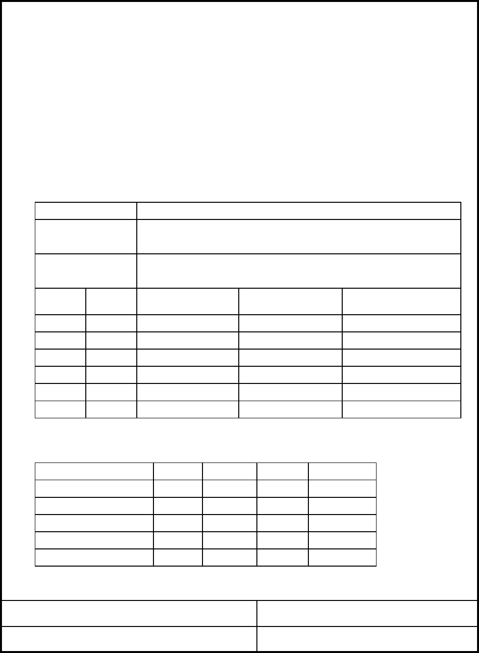
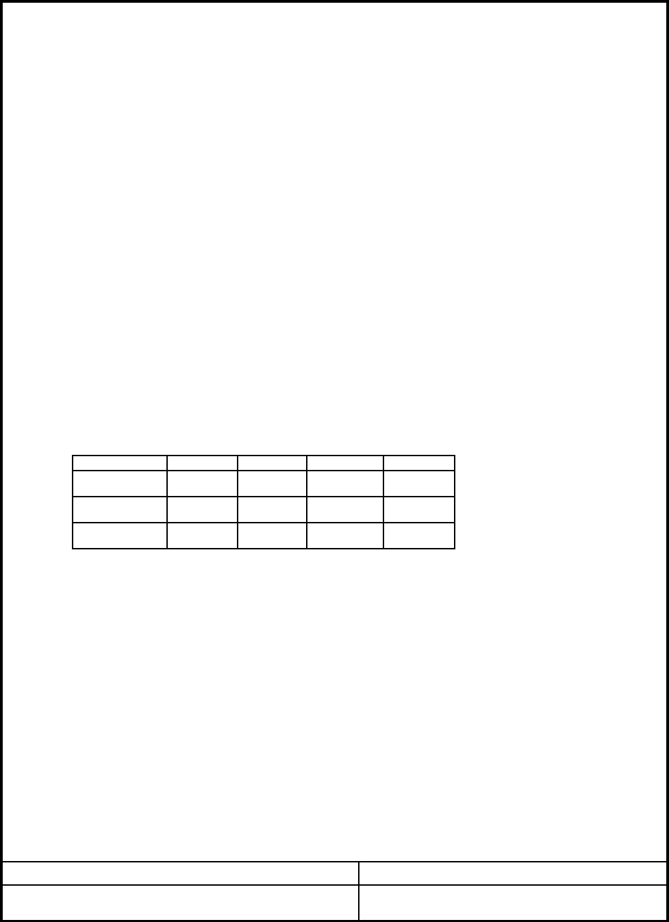
2.1 AC INPUT LINE REQUIREMENTS
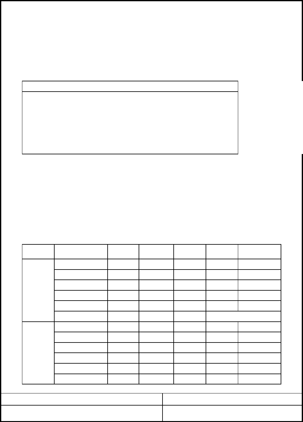
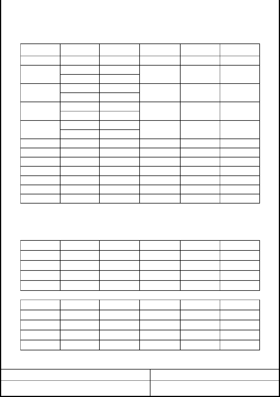
+3.3VDC
-12VDC
+5VSB
5%
Efficiency
350. Watt max Continuous
2. ELECTRICAL SPECIFICATION
1. INTRODUCTION
The "TNN350APF-V1" is a Power Supply designed to be used "ATX12V" form factor
The scope of this document is limited to the requirements of "ATX12V" PC form
5%
5%
MODEL NO: TNN350APF-V1 REV.0
POWER
8
ZALMAN SPECIFICATION
Vin(230VAC)
47
Vin(115VAC)
UNITParameter
Vin FREQUENCY
MIN
VACrms
VACrms
115
230
90
180
MAX
PAGE: 1/9
A
A
Hz
0A
Output
voltage Requla
-tion
+12VDC1
+5VDC
5%
5%
+12VDC2 5%
2.0A
Max load(Amps)
10.0A
20.0A
15.0A
ATX/ATX12V
380. Watt max peak
Peak current(Amps)Min load(Amps)
80% at Full load
server computer systems
1.1 SCOPE
DATE: 2005. 1. 17
1A
0.5A
0.5A
remote ON/OFF, cooling, standby voltage("VSB") and electrical characteristics.
-
135
265
63
15
1A
0A
Vin(115VAC)
NOM
2.5A
20.0A
0.3A
+3.3VDC "0.5
"
+12VDC
+5VSB
0.5+5VDC 3A
1.0 - 9A
DATE: 2005. 1. 17
"2.5A2A-
"2.5A2.0A
Amps5A
-
-
"
-
1.0
0.0
0.0
"0.3
"
-
14.1A-
"
Range
2) Maximum +5V and +3.3V output power shall not exceed 120Watts.
Parameter
+12VDC1 8A-
MAX
4) It shall not exceed 17 seconds in duration at Total +12VDC1, +12VDC2
output power, 300Watts.
"
1.0 12A "
+12.6 Volts
+4.75
-0.5
+12VDC2
+3.3VDC
+5VSB
1) Maximum continuous total DC output power shall not exceed 350Watts.
+5.00 Volts
+3.47
UNIT
Volts-12VDC
+4.75 +5.00
+12.00+12VDC1
+5VDC
Parameter
+5.25 Volts
-13.20
+5.25
10A
1.0 Amps
(High -
5A
ZALMAN SPECIFICATION PAGE: 2/9
+5VSB
0.3-0.0-12VDC
0.0
MODEL NO: TNN350APF-V1 REV.0
+3.3VDC
+5VDC
+12VDC
(Normal
Load)
Range 2
0.5
Load)
5) Output voltage of +5VSB shall be maintained within the power shut down.
3) Maximum Peak Total DC output power shall not exceed 380Watts.
2.2.2 DC output CURRENT
NOMMIN PEAK
Range 1
UNIT
TEST POINT : OUTPUT CONNECTOR LOAD TERMINALS.
MAXMIN NOM
Volts
2.1.1 INRUSH CURRENT
Max. inrush current shall not exceed 60 CA(Peak to Peak).
2.2 DC OUTPUT REQUIREMENTS
2.2.1 OUTPUT REQUIREMENTS
-12.00-10.80
+3.14
+11.4
-12VDC
+3.30
+12VDC2 +11.4 +12.00 +12.6 Volts
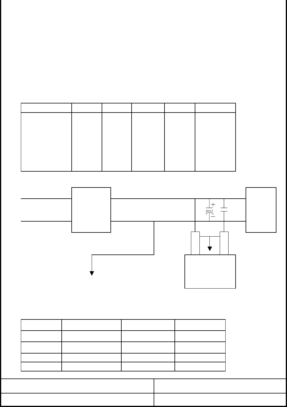
AC INPUT PSU LOAD
80 "
"
UNIT
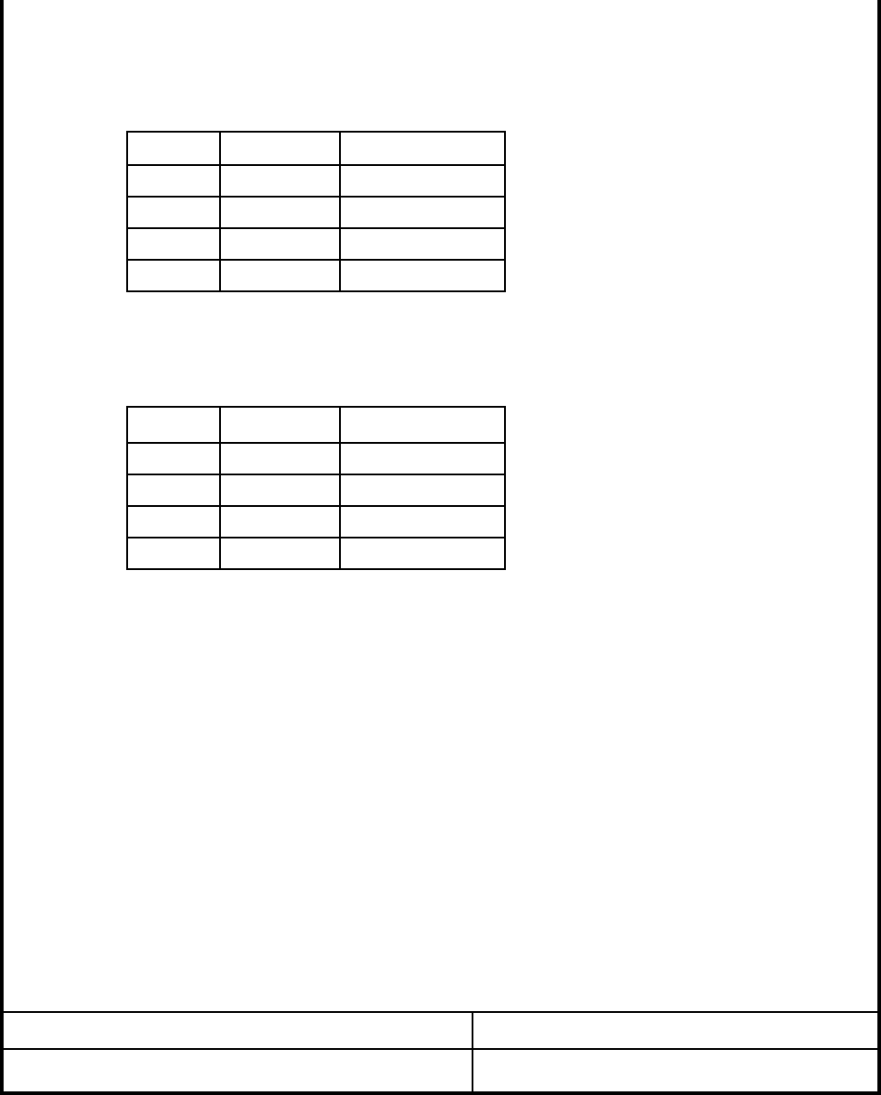
20MHz.
a 0.1uF Ceramic capacitors at each output with measuring band width from DC to
+3.3VDC
+5VDC 1.0% -
-1.0%
1.0% -
V return
AC NEUTRAL
-12VDC
mVp-p1.0% - 80
Parameter Range MIN
. The measurements should be made by crossing a 10uF electrolytic capacitor and
NOR
2.2.4 OUTPUT RIPPLE/NOISE
AC LIVE
SCOPE
"
1) The power supply at full load provide AC/DC conversion efficiency 80% minimum.
AC GROUND
120
80
10uF
. Load Slew Rate : 0.5A/us
2.2.5 Dynamic Loading
V OUT
+5VSB 1.0%
2.2.3 EFFICIENCY
+12VDC
MAX
0.1uF
50 "-
PAGE: 3/9ZALMAN SPECIFICATION
MODEL NO: TNN350APF-V1 REV.0 DATE: 2005. 1. 17
Capacitive Load
0.5A/us
1000uF
1000uF
1000uF
1uF
0.5A/us
+5VSB
Step Load Size Load Slew Rate
30% of max load
30% of max load
25% of max load
0.5A/us
0.5A/us
65% of max load
Output
+3.3V
+5V
+12V1,+12V2
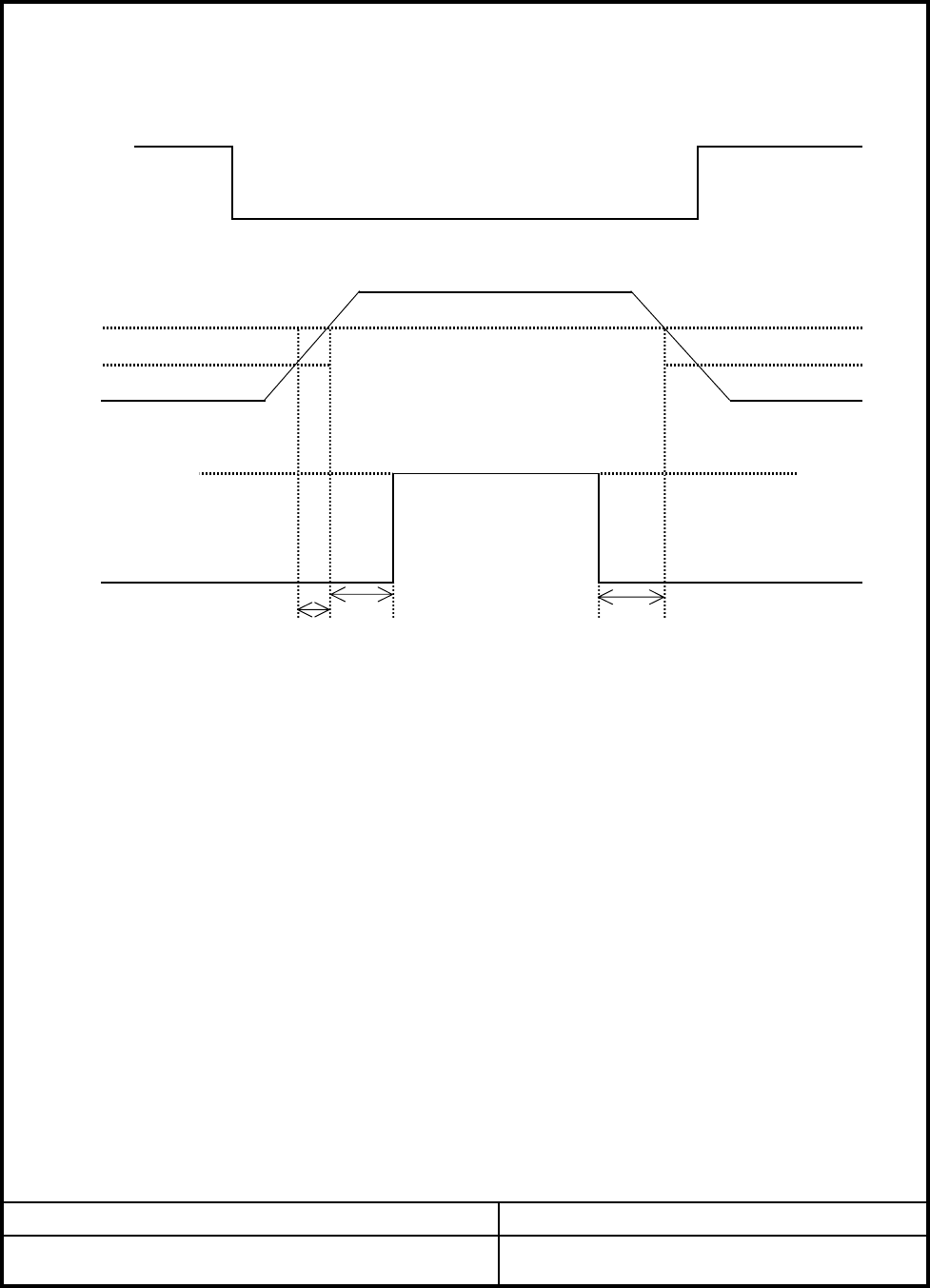
T2 T3
ZALMAN SPECIFICATION PAGE: 4/9
MODEL NO: TNN350APF-V1 REV.0
PS_ON
PS_OFF
* PW-OK sense level : 95% of nominal
2.3.1 REMOTE ON/OFF CONTROL
DATE: 2005. 1. 17
2.3.2 POWER UP DELAY
. When PS-ON is pulled to TTL low, the DC outputs are to be enabled.
. When PS-ON is pulled to TTL high or open circuited, the DC outputs are
to be disabled. Turn ON/OFF delay >- 1000ms
The power supply DC outputs (with the exception of +5VSB) shall be enabled with
AC power is present.
an active-low, TTL-compatible signal("PS-ON"). The +5VSB is on whenever the
DC Enable
95%
10%
T4
2.3 TIMING / HOUSE KEEPING
PWR-OK
The output voltages shall rise from <10% of nominal to within the regulation ranges
specified in sec 2.2.1 within 5 to 70ms.
Min UnitMax
. Power Down Warning : 1ms<T4<200ms
V
2.3.4 VOLTAGE HOLD-UP TIME
The power supply shall maintain output regulation per section 2.2.1 despite
a loss of input power at the low-end nominal range at maximum continuous
Parameter
2.4 OUTPUT PROTECTION
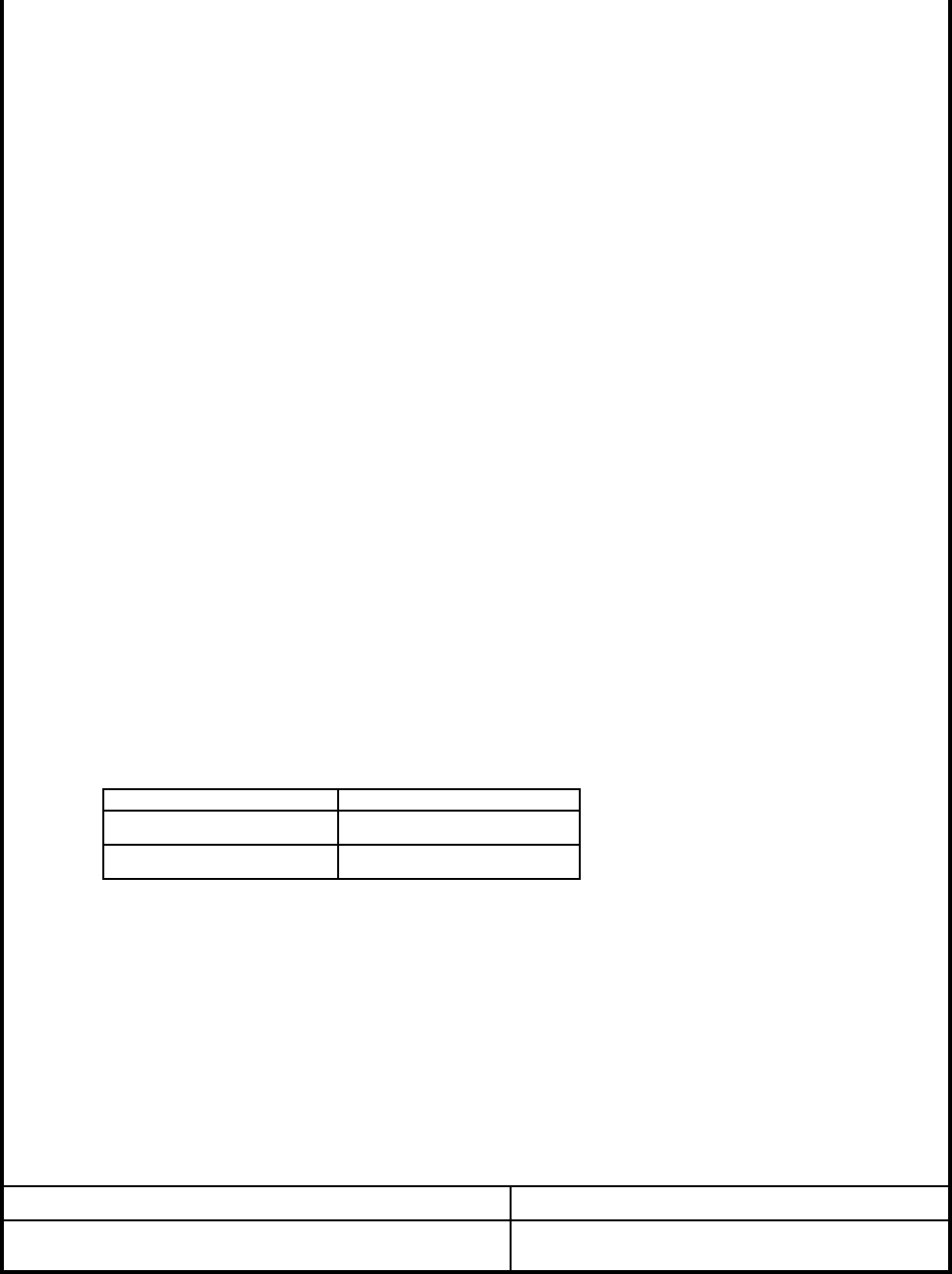
2.4.1. OVER VOLTAGE PROTECTION
+5VDC 5.74 6.3 7.0
+12VDC 13.4 15 15.6V
Nom
DATE: 2005. 1. 17
. +5V : 25A~ Test Condition : Output Full Load
. +3.3V : 25A~
. +12VDC1 : 18A~
PAGE: 5/9ZALMAN SPECIFICATION
MODEL NO: TNN350APF-V1 REV.0
. +12VDC2 : 18A~
. Logic level Low : <0.4V 4mA
+3.3VDC 3.76 4.2 4.3
*Change latch mode at above voltage in power supply unit.
2.4.2. SHORT CIRCUIT PROTECTION
. Shutdown or latch at short +3.3, +5V and +12V.
. No damage in compenents, PCB trace connector at continous shout.
. The maximum short circuit current shall not exceed 240VA.
2.4.3. OVER POWER PROTECTION
V
V
output load as specified in section 1.1 for a minimum 17ms.
2.3.3 POWER GOOD SIGNAL, POK
. Logic level High :Between 2.4VDC and 5VDC output while sourcing current, 2mA
. Signal Type : Open Collector +5VDC, TTL compatible.
. POK Delay : 200mS<T3<1000ms
. Primary to Secondary : 500VDC 100
. Primary to FG : 500VDC 100
DATE: 2005. 1. 17
ZALMAN SPECIFICATION PAGE: 6/9
MODEL NO: TNN350APF-V1 REV.0
Shall be 1.0mA Maximum at 220VAC Input
On
2.4.11. LEAKAGE CURRENT(IEC950)
. The Maximum Leakage Current Following The Frame / AC Sine Conductor
2.4.10. INSULATION VOLTAGE WITHSTAND
2.4.6. MEAN TIME BETWEEN FAILURES
. Operating Time 50,000HR at 25.
2.4.7. This power supply shall comply with the followings.
. CSA C22.2 NO220 & CSA Bulletin 1402C, Level3
Off
Control Signal
Logic " Low"
Logic " High"
Output Status
2.4.9. POWER SWITCH On/Off TEST
2.4.4 DC INPUT PROTECTION
. VDE 0806, EN60950 A3
. IEC950
2.4.5. BURN-IN
Primary lot is output full load at 55 24HR
. UL1950
. Use proper fuse for DC input over current protection.
2.4.8. EMI
. VDE 0871/6.78 Class B
. FCC Part 15 Sub Part J, Class B

. Operating : 5 ~ 40
2.4.13. TEMPRATURE RANGE
. Storage : -20 ~ 85
2.4.12. DIELECTRIC STRENGTH
. Between Input and Output : 1500VAC 10mA 1min or 1800VAC 10mA 3sec
. Between Input and FG : 1500VAC 10mA 1min or 1800VAC 10mA 3sec
. Polarity : +, -
. Phase : 0 - 360
. Mode : Common, Normal
2.4.14. HUMIDITY RANGE
. Operating : 20% ~ 80%
. Storage : 10% ~ 95%
. The power Supply Must not generate Acoustic Noise in excess of 30dB at a
2.4.15. VIBRATION TEST
. Non Operation : Sweep Test
. Frequency : 5 -> 20 -> 500 -> 5Hz
. Acceleration :0.02G
2.4.16. ACOUSTIC NOISE
. Airection : X, Y, Z
. Period : 6 Minutes
. Cycie : 10
Distance of 1 Meter from any Point on The requirments Surface.
MODEL NO: TNN350APF-V1 REV.0 DATE: 2005. 1. 17
ZALMAN SPECIFICATION PAGE: 7/9
2.4.18. AC LINE NOISE
. The Power Supply Shall Operate Normally When AC Line Noise is Applied
. Noise Crest Value : 1000VAC
. Pulse Width : 1us
. Time : 3Minutes
. PA
Orange+3.3VDC+3.3VDC 13Orange
Yellow
Yellow
Pin
Black 5
Wire Color
4 COM Black
Black
Pin
2.5.2. PERIPHERAL CONNECTORS
Signal Wire Color
7 COM
+5VDC
Black 19
+12VDC Yellow 22
Pin Signal Pin Pin
ZALMAN SPECIFICATION PAGE: 8/9
Black
COM Black
6
Yellow
+5VDC Red
MODEL NO: TNN350APF-V1 REV.0
Black
8
+12DC1
+12DC1
+12DC1
+12DC1
Black
Red
COM18
Signal Wire Color
+3.3VDC Orange
PS-1 Connector : MOLEX 39-01-2240 or equivalent
2.5. DC CONNECTOR REQUIVEMENTS
2.5.1 BASE BOARD CONNECTOR
Red
. 18AWG is suggested for all wire except for the 3.3V sense return wire, pin 13
Gray 20
9
Red10
8 POK
+5VDC+5VSB
7
2 COM Black
Processor Power Connector : MOLEX 39-01-2080 or equivalent
Yellow
Pin
1
Red
COM Black
+5VDC
12 +3.3VDC Orange
3 COM
Signal Wire Color
COM Black
DATE: 2005. 1. 17
+3.3VDC, and COM
24
11 +12VDC Yellow 23
+12DC2
5
6
3 COM Black
2sense Brown 14
sense Black
COM
Black
sense Red
416
COM
Blue
1
Pin Signal Wire Color
PS-ON Green
5sense Yellow
-12VDC
17 COM
15
Signal
Black 7 +12DC2
(22AWG) For 300W configurations, 16AWG is recommended all 12VDC, +5VDC,
Violet
+5VDC
21
Yellow
2 COM Black 6 +12DC2 Yellow
COM1
Yellow
4 COM Black 8 +12DC2 Yellow
3 COM
4 +12VDC1 Yellow
.+12V Power Connector
2 COM Black
3 COM Black
Wire Color
1 +5VDC Red
3 COM Black
4 +5VDC Red
1 +12VDC1 Yellow
2 COM Black
Signal Wire Color
. Contacts : AMP 61314-1 terminals or equivalent.
. Connector : AMP 1-480424-0 or Molex 8981-04P or equivalent.
MODEL NO: TNN350APF-V1 REV.0
ZALMAN SPECIFICATION PAGE: 9/9
. Connector : AMP 171822-4 or equivalent.
. PB(Floppy Drive Connector)
3.2. LABELING /MARKING
DATE: 2005. 1. 17
3. MECHANICAL
3.1. PHYSICAL DIMENSION
Pin Signal
Dimension : L * W * H mm
294*200*67
Pin

FCC Compliance Statement
Caution : Any changes or modifications in construction of this device which are not expressly
approved the party responsible for compliance could void the user's authority to operate the
equipment.
N
OTE : This equipment has been tested and found to comply with the limits for a Class B digital
device, pursuant to part 15 of the FCC Rules. These limits are designed to provide reasonable
protection against harmful interference in a residential installation. This equipment generates, uses
and can radiate radio frequency energy and, if not installed and used in accordance with the
instructions, may cause harmful interference to radio communications, However, there is no
guarantee that interference will not occur in a particular installation. If this equipment does cause
harmful interference to radio or television reception, which can be determined by turning the
equipment off and on, the user is encouraged to try to correct the interference by one or more of the
following measures:
- Reorient or relocate the receiving antenna.
- Increase the separation between the equipment and receiver.
- Connect the equipment into an outlet on a circuit different from that to which the receiver is
connected.
- Consult the dealer or an ex
p
erienced radio/TV technician for hel
p
.
This device complies with Part 15 of the FCC Rules.
Operation is subject to the following two conditions:
(1)This Device may not cause harmful interference, and
(2) This device must accept any interference received,
including interference that may cause undesired operation.