Zalman Tech ZM460-APS Power Supply User Manual Appendix F
Zalman Tech Co., Ltd. Power Supply Appendix F
Users Manual
22
ZALMAN SPECIFICATION
factor switching Power Supply. Especially, It is applied to the line input capability,
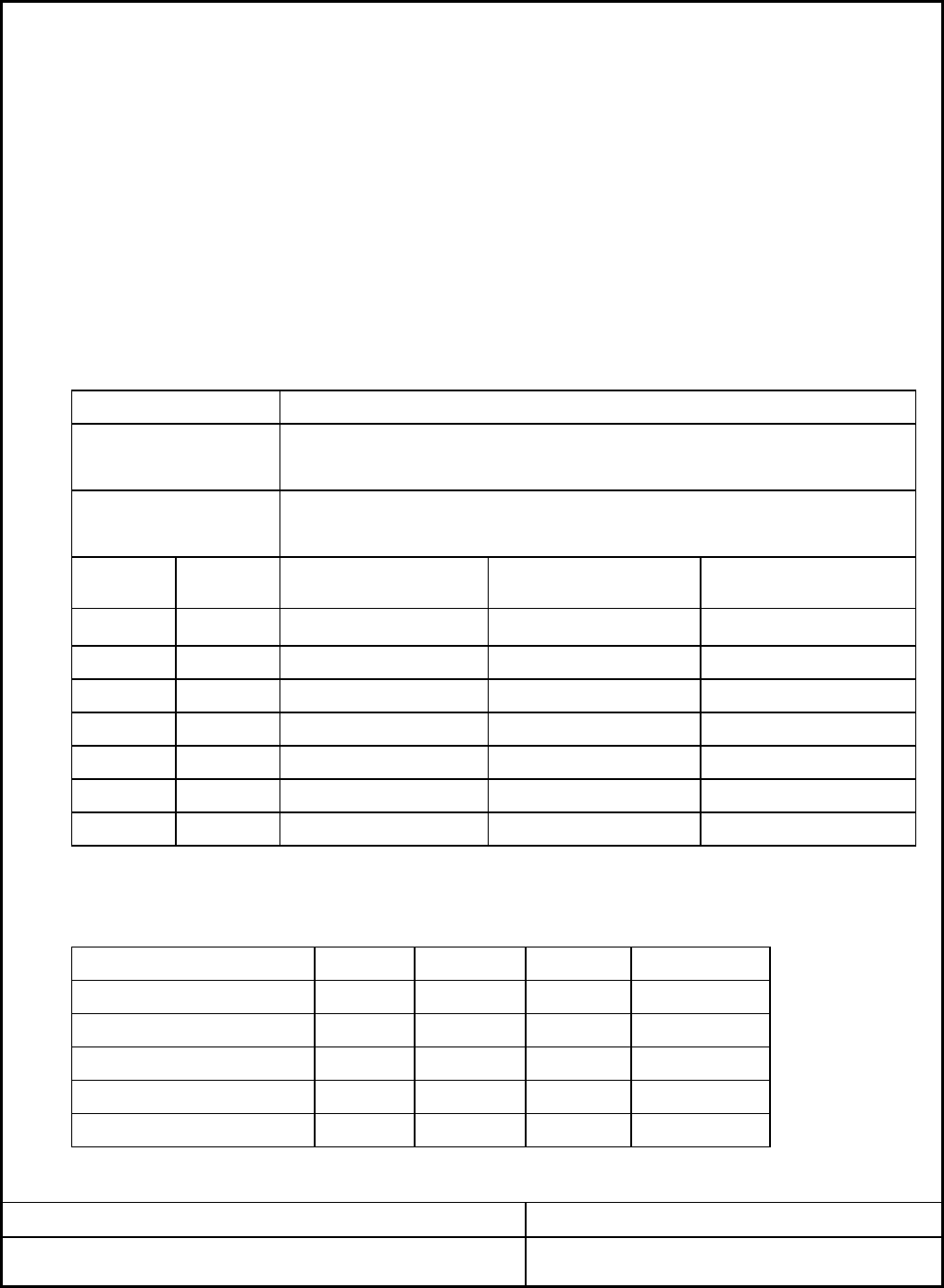
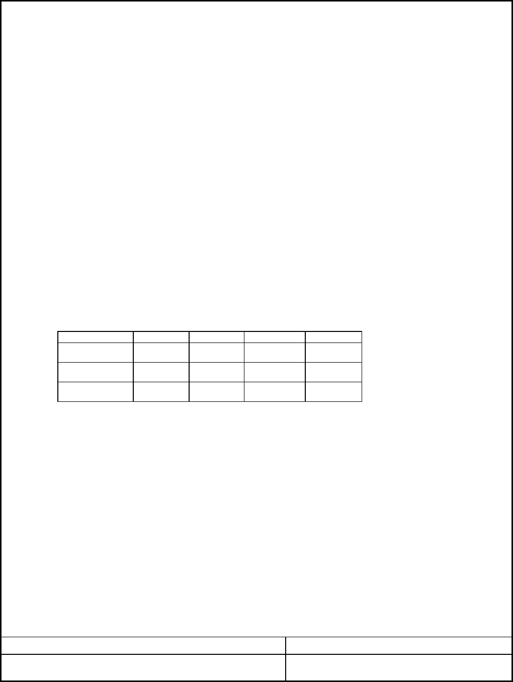
2.1 AC INPUT LINE REQUIREMENTS
+3.3VDC
-12VDC
+5VSB
±5%
Efficiency
460. Watt max Continuous
Form-factor
1. INTRODUCTION
The "ZM460-APS" is a Power Supply designed to be used "ATX/ATX12V" form factor
The scope of this document is limited to the requirements of "ATX/ATX12V" PC form
±5%
±5%
MODEL NO: ZM460-APS REV.1.1
POWER
Vin FREQUENCY
MIN
Vin(230VAC)
Vin(115VAC)
NOM
5
2. ELECTRICAL SPECIFICATION
Vin(230VAC)
90
180
47
Vin(115VAC)
Parameter
VACrms
VACrms
A
A
Hz
UNIT
115
230
MAX
PAGE: 1/9
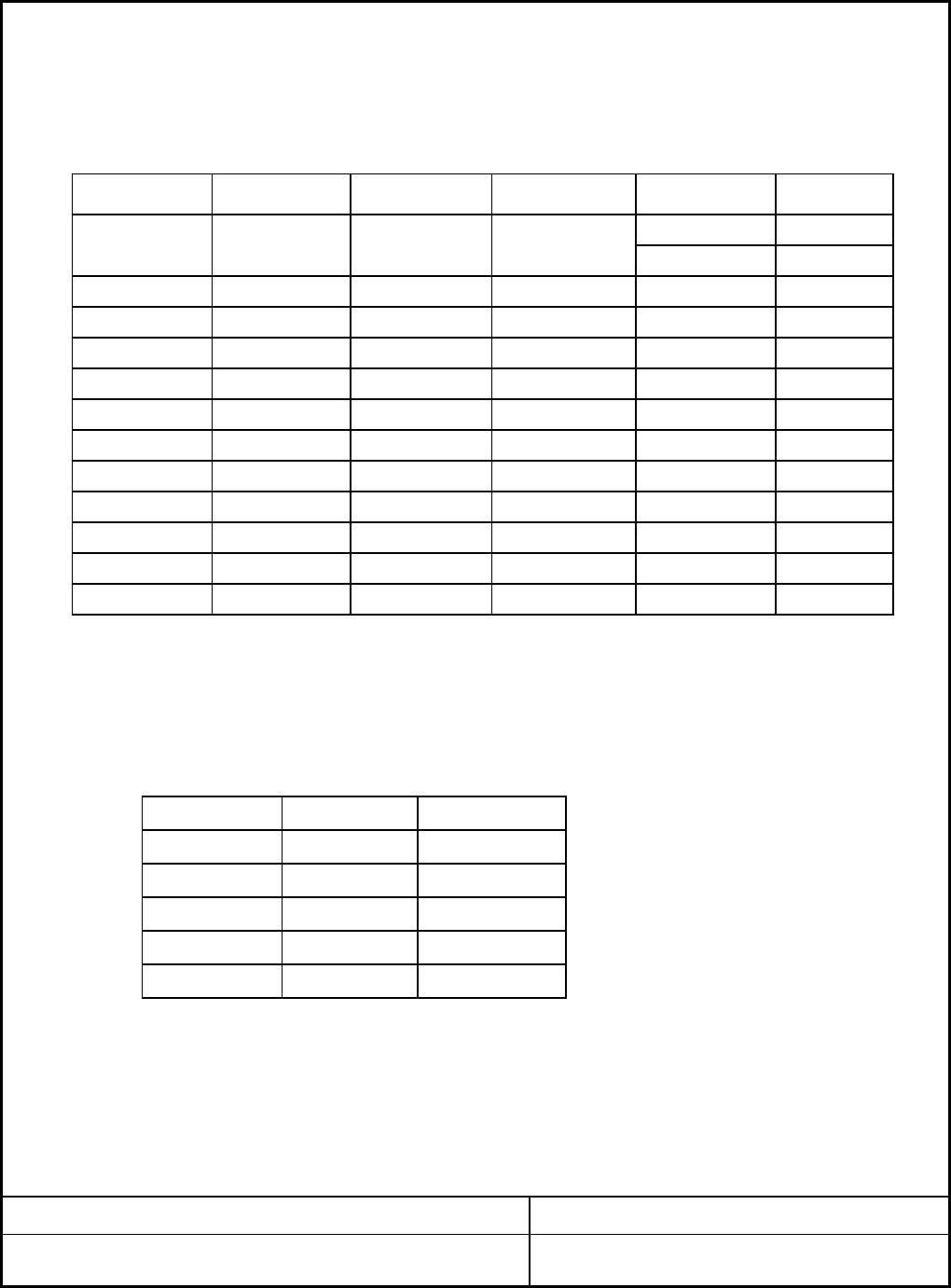
Output
voltage Requla
-tion
+12V2DC
+5VDC
±5%
±5%
+12V1DC ±5%
2.5A
Min load(Amps)
30.0A
0.8A
2A
Max load(Amps)
18
28.0A
0A
Peak current(Amps)
≥75% at Full load
1 16 19
0A
personal computers.
1.1 SCOPE
DATE: 2005. 03. 24
1
0.5A
0.3A
ATX/ATX12V
520. Watt max peak
remote ON/OFF, cooling, standby voltage("VSB") and electrical characteristics.
-
135
265
63
10
Amps+12V1DC 1.0
+12.6 Volts
-10
-
-
13
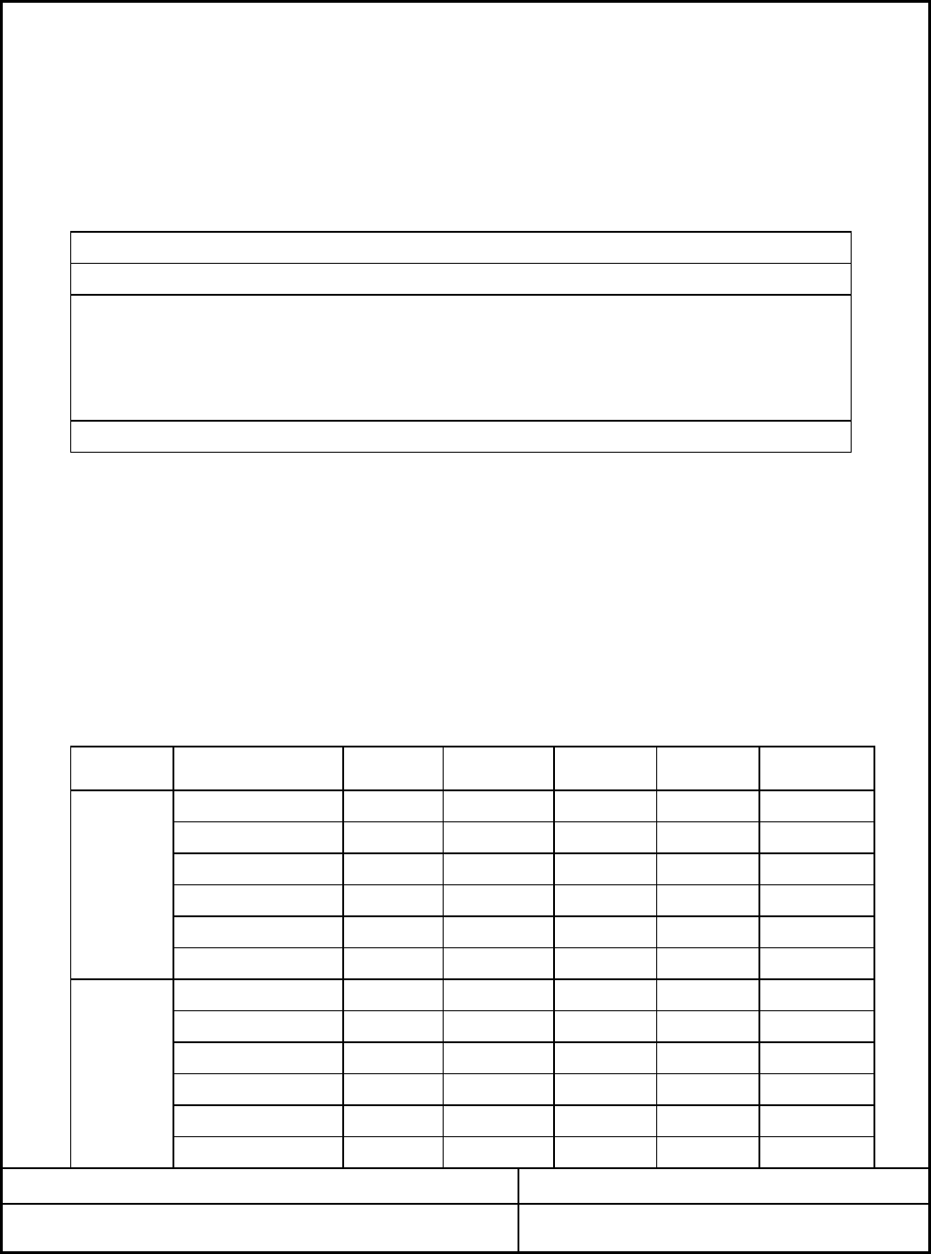
4) Maximum combined current for 12V outputs shall be 30A.
0.0
"
+12V2DC
+5VSB
0.5(normal +5VDC
+3.3VDC
-
-0.7
"3.0
"-
"-
"
-"-1.0
1.0
-
"10
"
13
-
+12.6 Volts
+12V2DC 1.0
-
MAX
4) Maximum combined peak current for 12V outputs shall be 36A.
PEAK
+5VSB
1) Maximum continuous total DC output power shall not exceed 460Watts.
±5% +5.00 Volts+4.75
2.2.2 DC output CURRENT
+12.00+12V1DC
+5VDC
+12V2DC ±5%+11.4 +12.00
±5% +11.4
-12VDC ±10%
+4.75 +5.00
+3.3VDC +3.30
-12.00-10.80
+3.14±5%
+5.25 Volts
-13.20
+5.25
Volts
+3.47
"
"
-
5.0
+5VSB
MODEL NO: ZM460-APS REV.1.1
Load) 0.3
ZALMAN SPECIFICATION PAGE: 2/9
0.0
-0.3--12VDC
DATE: 2005. 03. 24
0.0
Load)
Range 2
1.0
0.5
+3.3VDC
-12VDC
0.3
0.0
1.0
2) Maximum +5V and +3.3V output power shall not exceed 180Watts.
Parameter
+12V1DC Amps
3) Maximum Peak Total DC output power shall not exceed 520Watts.
5) Output voltage of +5VSB shall be maintained within the power shut down.
-
NOMMIN
(high 11-
16
+5VDC
Range
Range 1
±5%
UNIT
TEST POINT : OUTPUT CONNECTOR LOAD TERMINALS.
Parameter MIN NOMRange MAX UNIT
Volts
2.1.1 INRUSH CURRENT
Max. inrush current shall not exceed as 115V 70A-peak and 230V 100A-peak.
2.2 DC OUTPUT REQUIREMENTS
2.2.1 OUTPUT REQUIREMENTS
AC INPUT PSU LOAD
±1.0% -120 mVp-p+12V1DC
±1.0%
+5VDC ±1.0% 50
+3.3VDC
AC GROUND
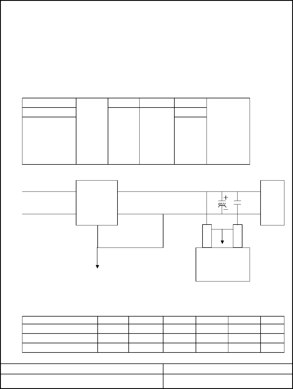
2.2.5 OUTPUT TRANSIENT RESPONESE & OVERSHOOT AT TURN ON/OFF
MAX step
Voltage range
0.1A
±3% ±3%
40% 60% 30%
V return
AC NEUTRAL
-12VDC
AC LIVE
+5VSB ±1.0%
±1.0% -
+3.3VDC -12VDC
2.2.3 EFFICIENCY
+12V2DC
. The measurements should be made by crossing a 10㎌ electrolytic capacitor and
Parameter Range
±1.0%
120
50
"
-
. Load Slew Rate : 0.2A/㎲
-
SCOPE
"
1) The power supply at full load provide AC/DC conversion efficiency
75%
minimum.
Parameter +5VSB
0.5A
+12V2DC +5VDC
2.2.4 OUTPUT RIPPLE/NOISE
UNIT
"
20MHz.
a 0.1㎌ Ceramic capacitors at each output with measuring band width from DC to
MAXNOR
-120
MIN
"-
0.1㎌
50 "-
10㎌
V OUT
Shoot range
DATE: 2005. 03. 24
-
30%
±10%
±3% ±3% ±3%
+12V1DC
PAGE: 3/9ZALMAN SPECIFICATION
±10% ±10%
MODEL NO: ZM460-APS REV.1.1
±10% ±10%
T2 T3
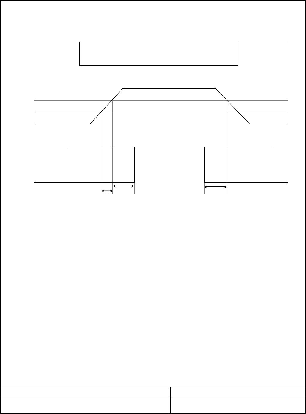
* PW-OK sense level : 95% of nominal
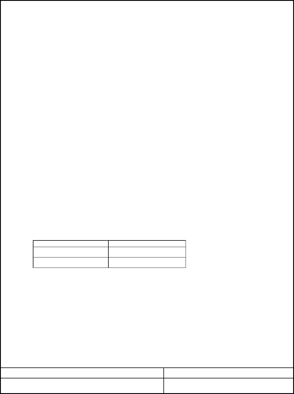
2.3.1 REMOTE ON/OFF CONTROL
PAGE: 4/9
MODEL NO: ZM460-APS REV.1.1 DATE: 2005. 03. 24
ZALMAN SPECIFICATION
95%
2.3.2 POWER UP DELAY
PS_ON
DC Enable
an active-low, TTL-compatible signal("PS-ON"). The +5VSB is on whenever the
AC power is present.
PS_OFF
. When PS-ON is pulled to TTL high or open circuited, the DC outputs are
to be disabled. Turn ON/OFF delay ≥ 1sec
The power supply DC outputs (with the exception of +5VSB) shall be enabled with
. When PS-ON is pulled to TTL low, the DC outputs are to be enabled.
10%
T4
PWR-OK
2.3 TIMING / HOUSE KEEPING
The output voltages shall rise from 10≤ T2 ≤90% of nominal to within the regulation
ranges specified in sec 2.2.1 within 0.1≤ T2 ≤20ms
UnitMin
. Logic level Low : <0.4V 4mA
. POK Delay : 100ms≤T3≤500ms
2.3.4 VOLTAGE HOLD-UP TIME
The power supply shall maintain output regulation per section 2.2.1 despite
Parameter Max
a loss of input power at the low-end nominal range at maximum continuous
7.0
. Power Down Warning : T4≥1ms
2.4 OUTPUT PROTECTION
2.4.1. OVER VOLTAGE PROTECTION
Nom
15.6V
V+5VDC 5.74 6.3
+12VDC 15
. +12V2 : 23A~ at 12V2 at no load
ZALMAN SPECIFICATION
MODEL NO: ZM460-APS REV.1.1
+3.3VDC 3.76
13.4
4.2 4.3
DATE: 2005. 03. 24
. +5V : 30A~ Test Condition : Output Full Load
. +3.3V : 32A~
. +12V1 : 21A~ at 12V1 at no load
PAGE: 5/9
V
. Signal Type : Open Collector +5VDC, TTL compatible.
*Change latch mode at above voltage in power supply unit.
2.4.2. SHORT CIRCUIT PROTECTION
. Shutdown or latch at short +3.3, +5V and +12V.
. No damage in compenents, PCB trace connector at continous shout.
. The maximum short circuit current shall not exceed 240VA.
2.4.3. OVER POWER PROTECTION
V
output load as specified in section 1.1 for a minimum 16ms.
2.3.3 POWER GOOD SIGNAL, POK
. Logic level High :Between 2.4VDC and 5VDC output while sourcing current, 200㎂
2.4.7. This power supply shall comply with the followings.
2.4.5. BURN-IN
Primary lot is output full load at 55℃ 24HR
. Primary to Secondary : 500VDC 100㏁
. Primary to FG : 500VDC 100㏁
On
2.4.10. INSULATION VOLTAGE WITHSTAND
. CSA C22.2 NO220 & CSA Bulletin 1402C, Level3
Control Signal
Logic " Low" Output Status
2.4.11. LEAKAGE CURRENT(IEC950)
. The Maximum Leakage Current Following The Frame / AC Sine Conductor
PAGE: 6/9
MODEL NO: ZM460-APS REV.1.1
ZALMAN SPECIFICATION
Shall be 1.0mA Maximum at 220VAC Input
2.4.6. MEAN TIME BETWEEN FAILURES
. Operating Time 50,000HR at 25℃.
OffLogic " High"
DATE: 2005. 03. 24
2.4.9. POWER SWITCH On/Off TEST
. VDE 0871/6.78 Class B
. IEC950
. UL1950
. VDE 0806, EN60950 A3
. Use proper fuse for DC input over current protection.
2.4.4 DC INPUT PROTECTION
. FCC Part 15 Sub Part J, Class B
2.4.8. EMI

. Between Input and Output : 1500VAC 10mA 1min or 1800VAC 10mA 3sec
. Storage : -20℃ ~ 85℃
2.4.12. DIELECTRIC STRENGTH
. Phase : 0 - 360˚
. Between Input and FG : 1500VAC 10mA 1min or 1800VAC 10mA 3sec
. Operating : 5℃ ~ 25℃
2.4.13. TEMPRATURE RANGE
. Polarity : +, -
. Mode : Common, Normal
2.4.14. HUMIDITY RANGE
. Operating : 20% ~ 80%
. Storage : 10% ~ 95%
. The power Supply Must not generate Acoustic Noise in excess of 38dB at a
2.4.15. VIBRATION TEST
. Non Operation : Sweep Test
. Frequency : 5 ⇒ 20 ⇒ 500 ⇒ 5Hz
. Acceleration :0.02G
2.4.16. ACOUSTIC NOISE
. Airection : X, Y, Z
. Period : 6 Minutes
. Cycie : 10
Distance of 1 Meter from any Point on The requirments Surface.
MODEL NO: ZM460-APS REV.1.1 DATE: 2005. 03. 24
ZALMAN SPECIFICATION PAGE: 7/9
2.4.18. AC LINE NOISE
. The Power Supply Shall Operate Normally When AC Line Noise is Applied
. Noise Crest Value : 1000VAC
. Pulse Width : 1㎲
. Time : 3Minutes
・ MOLEX Housing #675820000
・ MOLEX Terminal #675810000
2COM Black
1+12VDC Yellow
. Contacts : AMP 61314-1 terminals or equivalent.
MODEL NO: ZM460-APS REV.1.1 DATE: 2005. 03. 24
ZALMAN SPECIFICATION PAGE: 8/9
5+3.3VDC Orange
4
Red
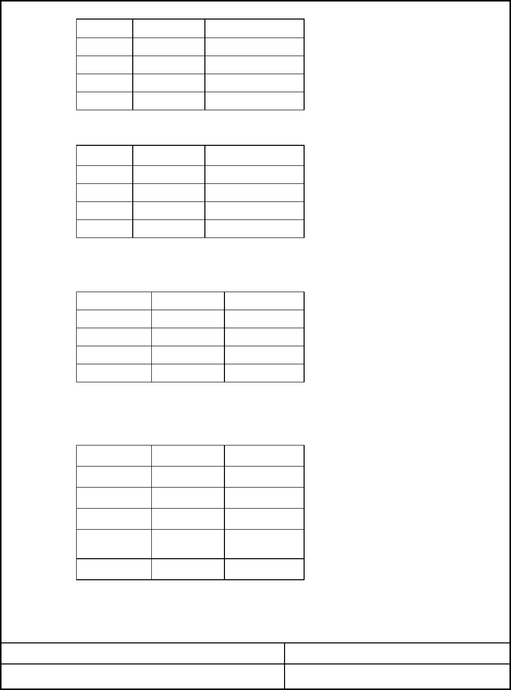
2.5.3. PERIPHERAL CONNECTORS
. Connector : AMP 1-480424-0 or Molex 8981-04P or equivalent.
+3.3VDC, and COM
2.5.2 Serial ATA Power Conector
COM Black
3+5VDC
COM Black
. 18AWG is suggested for all wire except for the 3.3V sense return wire, pin 13
(22AWG) For 300W configurations, 16AWG is recommended all 12VDC, +5VDC,
12 +3.3VDC Orange 24
+5VDC Red
10 +12VDC
11 +12VDC Yellow 23
Yellow 22
N.C
+5VDC Red
+5VDC Red
9+5VSB Violet 21
8POK Gray 20
7COM Black 19
Green
COM Black
COM Black
Black
5COM Black 17
6+5VDC Red 18
+5VDC Red 16
COM
PS-ON
-12VDC Blue
3COM Black 15 COM Black
2+3.3VDC
1+3.3VDC Orange 13 +3.3VDC Orange
sense Brown
2.5. DC CONNECTOR REQUIVEMENTS
2.5.1 BASE BOARD CONNECTOR
・ Connector : MOLEX 39-01-2240 or equivalent
Pin Signal Pin Pin Signal Wire Color
・ Contacts : Molex #5556 or equivalent
Wire Signal Wire Color
Orange 14
4
3. MECHANICAL
3.1. PHYSICAL DIMENSION
Dimension : 156 * 146 * 86 mm
2COM Black
1+12VDC Yellow
4COM Black
3+5VDC Red
2.5.4 Floppy Drive Connector
・ Connector : Molex 39-01-2040 or equivalent.
3COM Black
4+12VDC Yellow
ZALMAN SPECIFICATION PAGE: 9/9
MODEL NO: ZM460-APS REV.1.1 DATE: 2005. 03. 24
2.5.5 PCI Express High-End Graphics Power Cards Connectors
Wire Signal
・ Connector : Molex 45559-0002 or equivalent.
・ Contacts : Molex #5556 or equivalent.
COM Black
3+12VDC Yellow
2.5.5 +12V Power Connector
・ Contacts : Molex 44476-11111 or equivalent.
2COM Black
Pin Signal Wire Color
Pin Signal Wire Color
1+5VDC Red
2
12-4 +5VDC Red
・ Connector : AMP 171822-4 or equivalent.
23-2 COM Black
24-3 COM Black
Wire Color
11-1 +12VDC Yellow
1COM Black
Pin Signal
4+12VDC Yellow
18AWG Wire
5+3.3VDC Orange