Zebra Technologies 2119976501 RFID Reader User Manual
Zebra Technologies Corporation RFID Reader
User manual
©2016 ZIH Corp. All rights reserved. Zebra and the stylized Zebra head are trademarks of ZIH Corp., registered in many jurisdictions worldwide. All other
trademarks are the property of their respective owners.
21-199765-01 Integration Guide
Document # MN000026A03
©2016 ZIH Corp. All rights reserved. Zebra and the stylized Zebra head are trademarks of ZIH Corp., registered in many jurisdictions worldwide. All other
trademarks are the property of their respective owners.
1 Introduction
1.1 Background
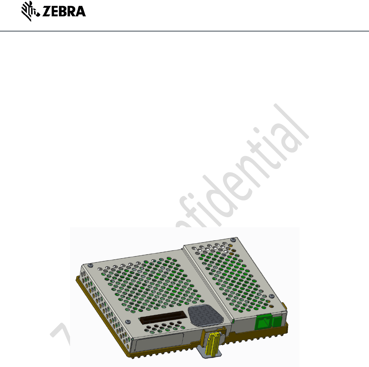
The 21-199765-01 Module is intended as an RFID reader which is integrated into a larger
product to provide embedded RFID reader capability. It is intended to use the antenna system
of the larger product and can get power and communication from an external source.
1.2 Purpose
The purpose of this document is to provide a guideline for product designers when integrating
the 21-999765-01 RFID Module.
1.3 Part Number
Part Number
SKU
21-199765-01
US/Canada RFID Module
1.4 Key Features
The 21-199765-01 RFID module will provide real time tag reading/processing for EPC Class 1
Gen2 compliant tags.
The communication interface is 10/100 baseT Ethernet
The Power interface is either Power over Ethernet iaw 802.3af/at or 24V DC Power Adapter
Up to 1W TX power over each of the 8 Coaxial contacts(only one at a time)
Heat sink and vented Metal enclosure for RF shielding and thermal control with convection
cooling (no additional heat sink required).
Custom housing for slide on bracket mounting.
2 Architecture
2.1 System Architecture
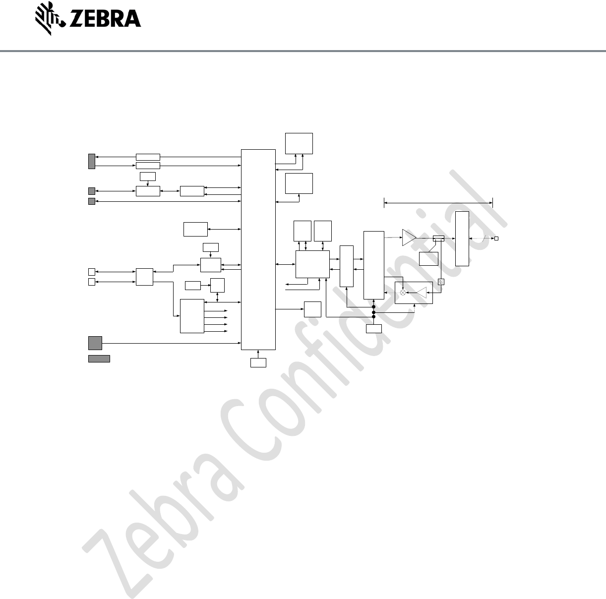
The Architecture of the 21-199765-01 is based on the Zebra Next Generation Engine RFID
reader. The reader contains a Transmitter section, Receiver section, Synthesizer section, a
Digital Modem, and a Host Interface section.
The Transmitter section contains a digital-to-analog converter (DAC), I-Q modulator, filtering, RF
power amplifier and the antenna multiplexer circuit. Communication with RFID tags is

©2016 ZIH Corp. All rights reserved. Zebra and the stylized Zebra head are trademarks of ZIH Corp., registered in many jurisdictions worldwide. All other
trademarks are the property of their respective owners.
accomplished using a half-duplex signal consisting of a modulated reader signal followed by a
Continuous Wave (CW) signal. The modulated signal sends data to the tag. The tag decodes this
signal and then Backscatters (uplinks) its data during the CW portion of the cycle. The
Transmitter (downlink) modulation used for communication with RFID tags is Double Sideband
Amplitude Shift Keying (DSB-ASK) or Phase Reversal Amplitude Shift Keying (PR-ASK), depending
on tag type and reader operating mode. Data rates range from 40 to 160 kbps.
The Receiver section contains I-Q demodulator, filtering and an analog-to-digital (ADC)
converter. The Receiver architecture is direct conversion, and therefore it operates using the
same Local Oscillator (LO) frequency and RF channel used by the Transmitter. During the
Backscatter (uplink) portion of the tag communication cycle the Receiver down-converts the
modulation data from the tag to baseband, where it is amplified and low pass filtered before
being converted to a digital signal by the ADC converter. The receiver accommodates tag
Backscatter data rates range from 32 to 640 kbps, depending on tag type and reader operating
mode.
The Synthesizer section contains a voltage-controlled oscillator (VCO) and phase-locked loop.
The Synthesizer generates a Local Oscillator (LO) signal that is shared with the Transmitter and
Receiver sections. The VCO operating frequency is constrained under software control to the
902 to 928 MHz UHF ISM band when configured for the FCC region.
The Digital Modem includes the DSP, dual-function ADC-DAC converter, and general purpose
input/output communication interfaces. The Digital Modem has direct control over transceiver
functions, including operating frequency, TX power control, and generation and decoding of
baseband digital modulation data sent and received by the reader for RFID tag read and write
operations.
The Host interface section includes a microprocessor, its associated memory, and all of the
circuitry needed to implement the Ethernet interface. The host processor serves as the
interface between the radio and the outside world.
©2016 ZIH Corp. All rights reserved. Zebra and the stylized Zebra head are trademarks of ZIH Corp., registered in many jurisdictions worldwide. All other
trademarks are the property of their respective owners.
2.2 Block Diagram
Microprocessor
(TI AM3505
@ 600MHz)
RMII
SDRC
UART2
DDR2 SDRAM
128MB – 512MB
Opto-Isolators
GPO (x3)
GPI (x2)
GPIO-OUT
GPIO-IN
Reset
Button RST_IN
GPIO
GPIO
RST
Serial
1.8V
3.3V
PMIC &
POWER
SUPPLY
RMII
ETH PHY
5V
RTC
NAND Flash
256MB – 1GB
GPMC
POE
Controller
I2C1
I2C
USB Host
XCVR
USB Host Port USB Host
USB Client Port
HSUSB1
USB0
5Vdc
10/100bT POE/POE+
12 – 48Vdc
10/100bT
LED_CTL LED
(x4)
GPIO
1.2V
Echo
Cancel
PA
LNA
DSP
(AD BF561)
SDRAM
64MB FLASH
4MB
MXFE Modulator
(ADF9010)
RF
Switch
USB Hub
UART3
SERIAL
Factory Test
Serial Access
(test points)
GPIO-OUT
GPIO-IN
Opto-Isolators
24MHz
38.4MHz
32.768
KHz
26MHz
50MHz
50MHz
166MHz
124.8MHz
60MHz
RF @ 902 – 928MHz
8 Port RF
Interface
SAW
BPF
8
Not Accessible on
FX7508
Figure 1 21-199765-01 Block Diagram
3 Hardware Interfaces
3.1 Ethernet Interface
The communication interface on the 21-199765-01 Module is a standard shielded RJ-45
connector that represents the 10/100BaseT interface. This connector also enables powering the
module with POE in accordance with 802.3af/at.
3.2 DC Power Interface
The DC Jack is adjacent to the RJ-45 connector and provides a auxiliary method of powering the
module using a Zebra approved DC Power Adapter (Zebra P/N PWRS-14000-260R)
3.3 RF Antenna Interface
The RF Interface on the 21-199765-01 Module is a custom 8-port MMCX connector (Molex P/N
73358-1170). This connector is used to interface to the RFID antenna system. The characteristic
impedance of the RF antenna interface connector is 50 ohms nominal.
©2016 ZIH Corp. All rights reserved. Zebra and the stylized Zebra head are trademarks of ZIH Corp., registered in many jurisdictions worldwide. All other
trademarks are the property of their respective owners.
4 Specifications
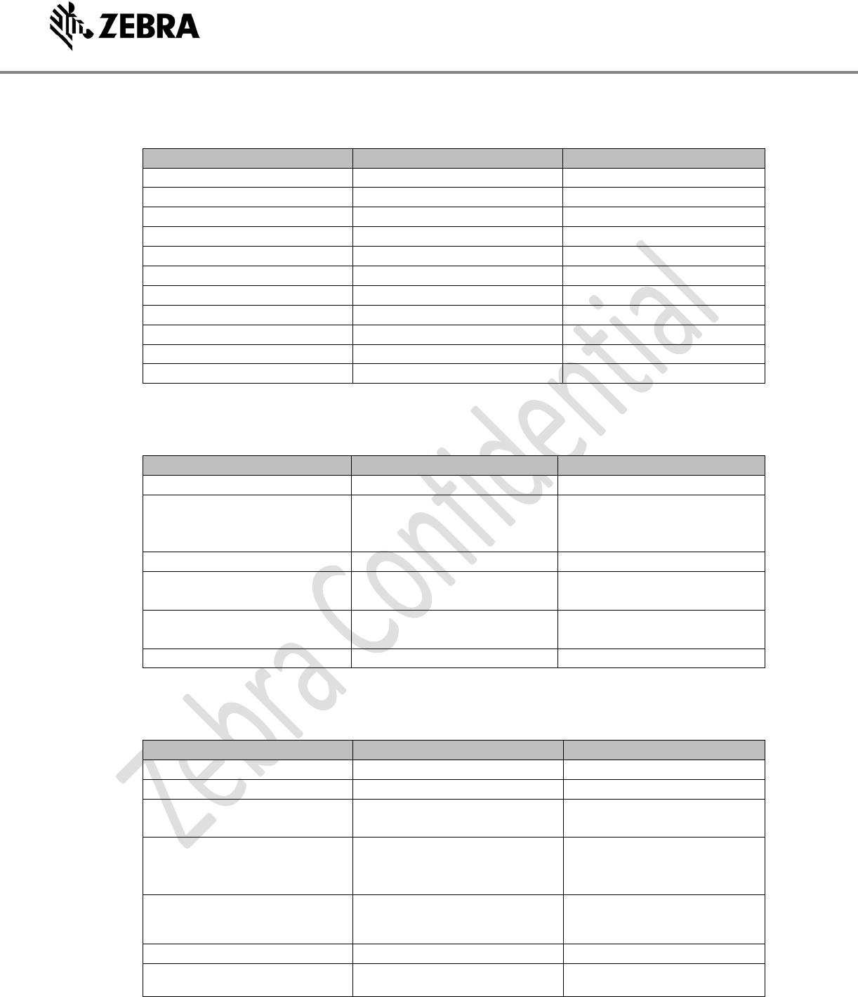
4.1 Physical and Environmental Specifications
Parameter
Specification
Notes
Size
7.52 x 5.52 x 1.4”
Weight
1.6 lbs
Base Material
Die Cast Aluminum
Mounting
Custom Bracket
Operating Temperature
-20C to +55C
Storage Temperature
-40C to 70C
Humidity
5 to 95% non-condensing
Shock/Vibration
Mil-Std-810G
ESD
+8kV Contact/+15kV Air
4.2 Electrical Specifications
Parameter
Specification
Notes
Frequency Range
902-928 MHz
US/Canada
Transmit Power
+10 to +31.5dBm
Limited to +30dBm Conducted
at antenna interface. For
professional installation only.
Power Consumption
13W(.af), 18W(.at/POE+)
Voltage Range
37V to 57V (POE)
12V to 48V (DC)
Use Zebra recommended 24V
power adapter
Antenna Ports
50 ohm monostatic
8 ports(Molex P/N 73358-
1170
Communications
10/100 BaseT Ethernet(RJ-45)
POE support
4.3 Hardware/OS and Firmware Management
Parameter
Memory
Flash 512MB;DRAM 256 MB
OS
Linux
Firmware Upgrade
Web-based and remote
firmware upgrade capability
Management Protocol
RM 1.0.1(with XML over
HTTP/HTTPS and SNMP
binding)
Network Services
DHCP, HTTPS, FTPS, SFPT,
SCP, SSH, HTTP, FTP, SNMP
and NTP
Network Stack
IPv4, IPv6
Security
Transport Layer Security Ver.
1.2, FIPS 140-2 Level 1
©2016 ZIH Corp. All rights reserved. Zebra and the stylized Zebra head are trademarks of ZIH Corp., registered in many jurisdictions worldwide. All other
trademarks are the property of their respective owners.
Air Protocol
EPCglobal UHF Class 1 Gen2,
ISO 18000-6C
Receiver Sensitivity
-82 dBm
IP Addressing
Static and Dynamic
Host Interface Protocol
LLRP v1.0.1
API Support
Host Applications – .NET, C
and Java EMDK;
Embedded Applications – C &
Java SDK
5 Integration Guidelines
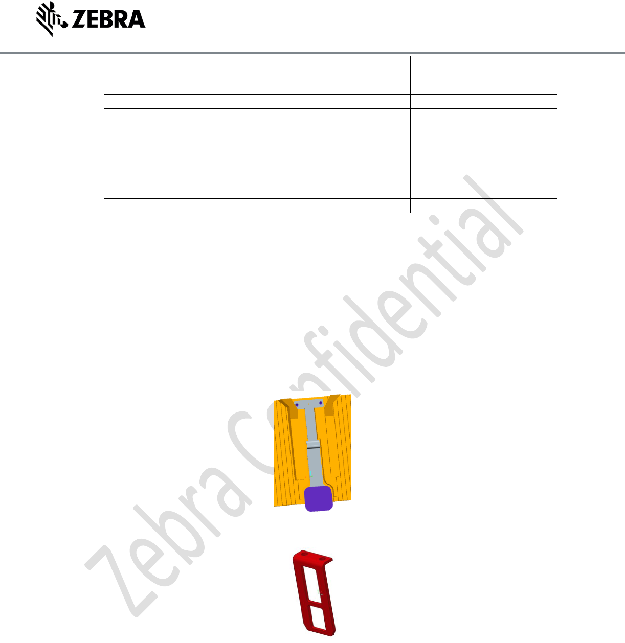
5.1 Mounting
The 21-199765-01 is to be mounted using a bracket that latches on to the latch on the back of the 21-
199765-01 Module. There is no requirement for screws or heat sinking once the bracket is installed
onto the final product. The module will slide on and latch into the bracket. Details of the bracket are
available upon request.
Figure 2 Rear Latch on 21-199765-01
Figure 3 Bracket used to mount 21-199765-01
5.2 Electrical Connection
The electrical connections on the 21-199765-01 are the Ethernet connection, the optional DC power
connection, and the 8-Port Antenna connection.
©2016 ZIH Corp. All rights reserved. Zebra and the stylized Zebra head are trademarks of ZIH Corp., registered in many jurisdictions worldwide. All other
trademarks are the property of their respective owners.
5.2.1 Ethernet Connection
Using a standard Cat5e/Cat6 UTP cable connect the 21-199765-01 module to an Ethernet switch or PC.
If the end application is using POE, a POE injector or Midspan should be connected between the 21-
199765-01 Ethernet connector and the Ethernet switch/PC.
5.2.2 Optional DC Power Connector
If POE is not the power source for the 21-199765-01 module, a DC Barrel Jack type power supply(Zebra
P/N PWRS-14000-260R) may be used to provide power to the module and the Ethernet connection can
now be made directly to the Ethernet switch or PC.
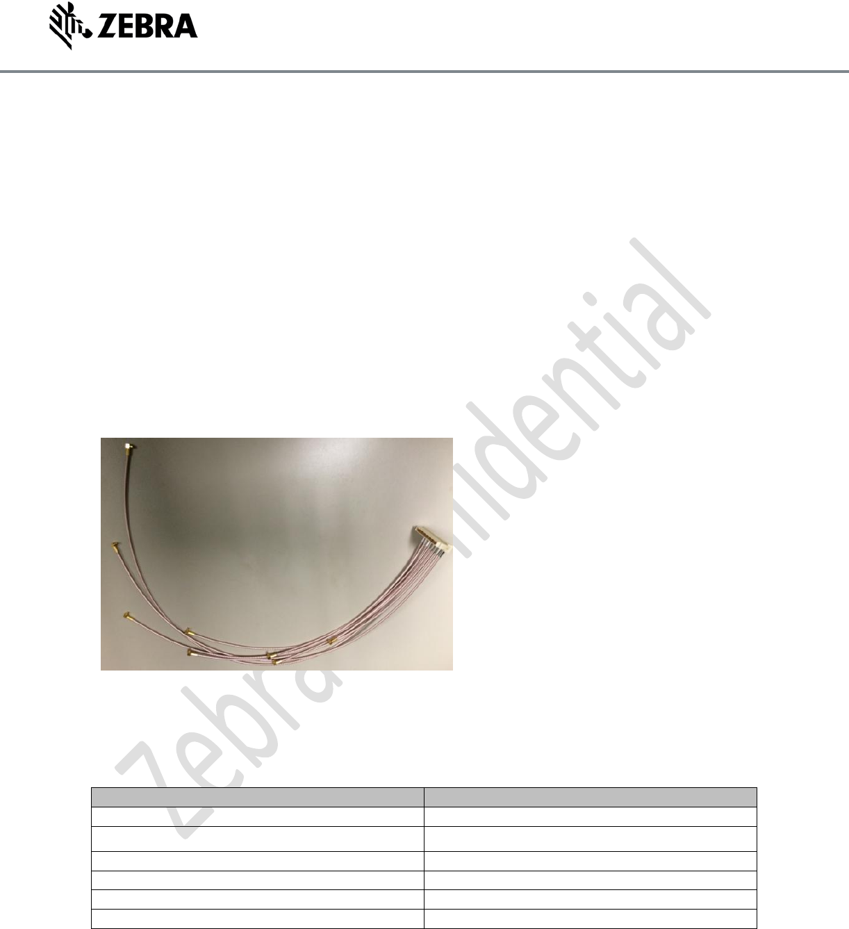
5.2.3 Antenna Connections
An RF Cable Harness similar to the one shown below is used to connect the 21-199765-01 to the System
Antenna(s). The Antenna Harness part number is Molex SD-73358-116. This harness can be used to
connect up to 8 50 ohm Antennas. The Antenna interface connection for this cable harness should be
MMCX Female.
Figure 4 Antenna Harness for 21-199765-01
6 Antenna Requirements
6.1 Antenna Specifications for use with the 21-199765-01 Module
Parameter
Specification
Frequency Range
902MHz to 928MHz
Polarization
Linear or Circular
Beamwidth
72 deg typical(Antenna dependant)
VSWR
<1.5:1
Gain
6dBi linear(typ) or 9dBic(Circular)-See Note 1
Connectors
RG316/MMCX-MPRF
Note 1: The antenna used for 21-199765-01 should be professionally installed and must adhere to the
FCC Part15 limits.
©2016 ZIH Corp. All rights reserved. Zebra and the stylized Zebra head are trademarks of ZIH Corp., registered in many jurisdictions worldwide. All other
trademarks are the property of their respective owners.
7 Regulatory Requirements
Add a Labeling Section and a Documentation Section
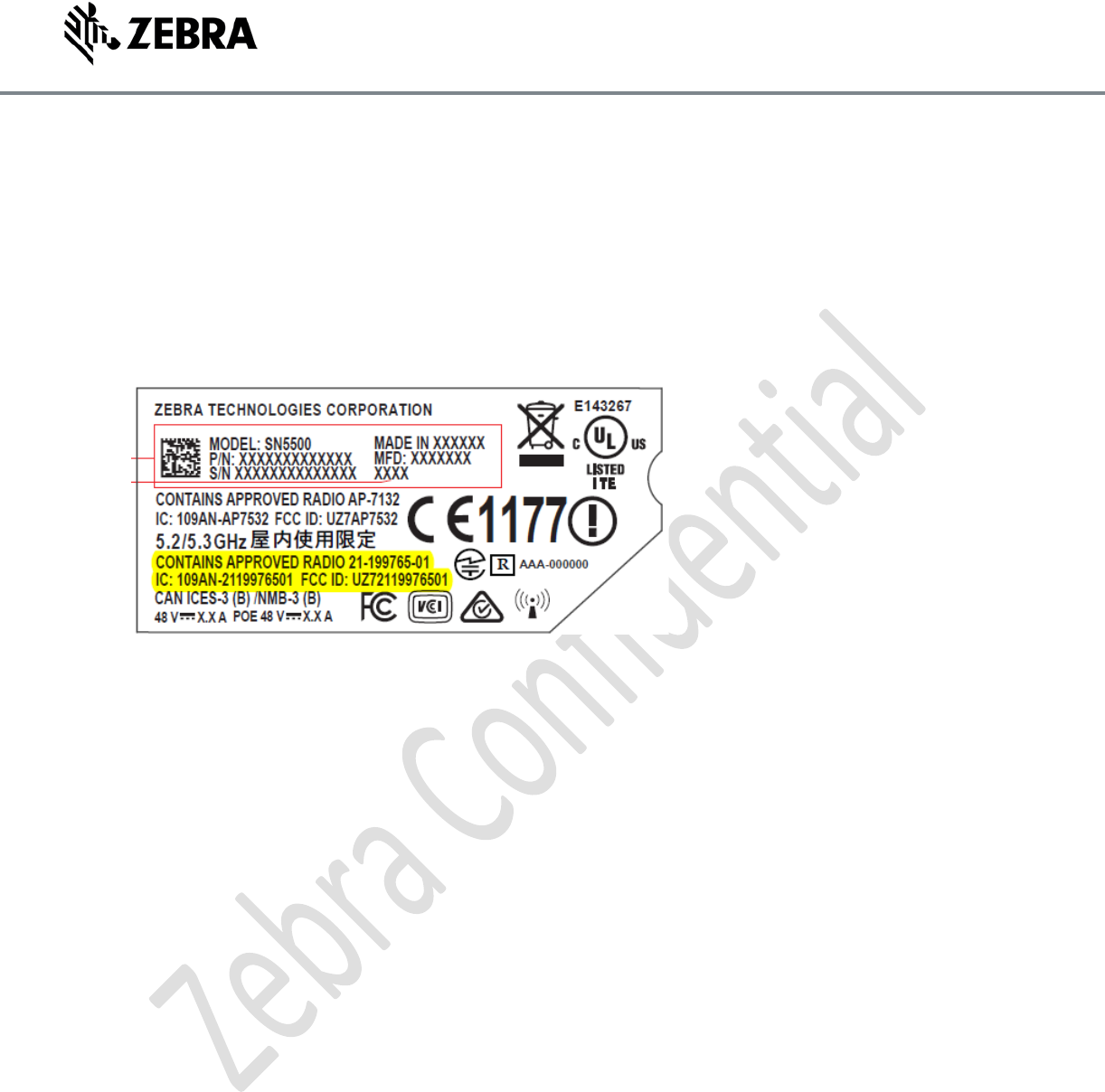
7.1 Host Labeling:
The FCC and Industry Canada require that the FCC ID and the Canadian Listing ID be visible on the end
unit. If the label on the module is not visible when the radio module is installed, the contents of the
label must be placed on a permanently attached label on the outside of the device.
See example of required labeling for a Host device that contains the radio module,
7.2 Module Documentation:
The following statements must be included in the Host Documentation
To comply with FCC RF exposure requirements, antennas that are mounted externally at remote
locations or operating near users at stand-alone desktop of or similar configurations must operate with
a minimum separation distance of 34 cm from all persons.
This device complies with Part 15 of the FCC Rules. Operation is subject to the following two conditions:
(1) this device may not cause harmful interference, and (2) this device must accept any interference
received including interference that may cause undesired operation.
This device complies with Industry Canada’s license-exempt RSSs. Operation is subject to the following
two conditions:
(1) This device may not cause interference; and (2) This device must accept any interference, including
interference that may cause undesired operation of the device.
Cet appareil est conforme exempts de licence le flux RSS de Industrie Canada. Son fonctionnement est
soumis aux deux conditions suivantes:
(1) Ce dispositif ne peut causer des interférences; et (2) Cet appareil doit accepter toute interférence, y
compris les interférences qui peuvent causer un mauvais fonctionnement de l'appareil.