Zebra Technologies 7528PA GSM/GPRS/UMTS/HSPA+ Module User Manual RA3051 Installation Sheet
Zebra Technologies Corporation GSM/GPRS/UMTS/HSPA+ Module RA3051 Installation Sheet
Contents
- 1. Host Regulatory Guide
- 2. Host User Guide
- 3. Installation Guide
Installation Guide
Warning: Installation of any components must be performed using appropriate anti-static devices. If unavailable, dis-
charge body static by touching a grounded metallic object before opening any covers on the hand-held.
Note: If the unit does not have an imager or scanner end-cap attached, the WA6212 long blank end-cap is required.
The WA6212 end-cap is not included in the RA3051 kit. It must be ordered separately.
The RA3051 radio kit includes the UMTS PHS8-P Expansion Module along with the following:
• M2x4 Torx T6 screws (x4)
• GPS jumper cable
• WAN main antenna
• WAN diversity antenna
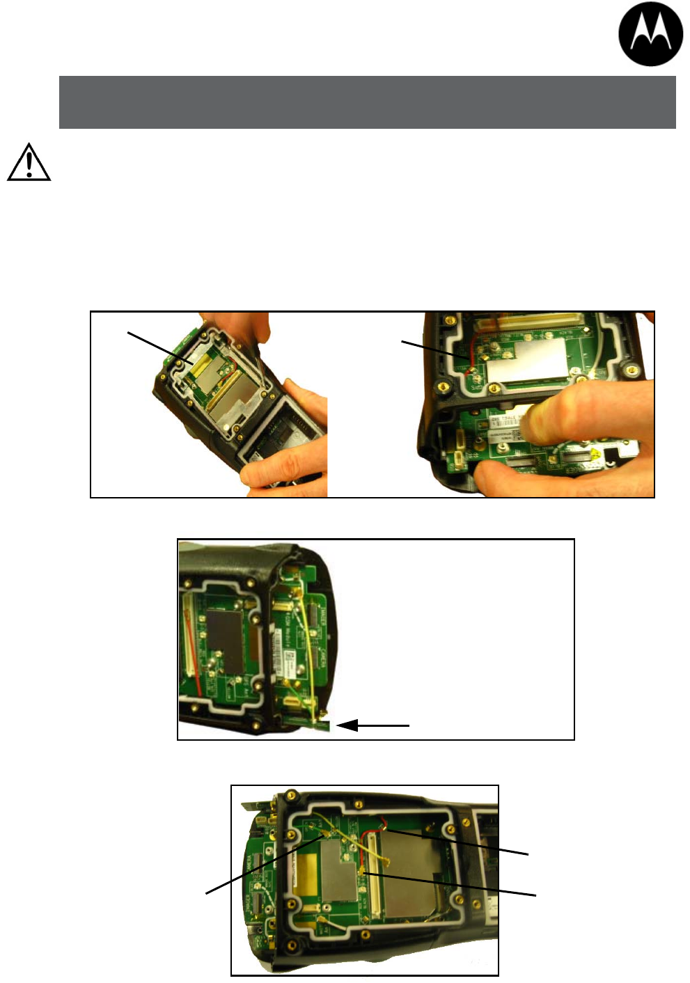
1. Remove the end-cap (x4 screws) and back cover (x6 screws).
2. Remove the metal frame (x4 screws), and remove the existing Wi-Fi antenna.
3. Slide the Diversity Antenna into the grooves along the right side of the unit.
4. Route the cables as indicated on the board – insert the red Wi-Fi antenna into the socket labelled Red and the
green GPS antenna into the socket labelled Green. Secure the cables by routing them through the clips.
Wi-Fi antenna
Metal
frame
Wi-Fi Diversity antenna
Wi-Fi Main antenna (red)
GPS antenna (green)
Route cables through clips
© 2014 Motorola Solutions, Inc. All Rights Reserved.
MOTOROLA, MOTO, MOTOROLA SOLUTIONS and the Stylized M Logo are trademarks or registered trademarks of Motorola Trademark
Holdings, LLC and are used under license. All other trademarks are the property of their respective owners.
February 18, 2014
8000323A
RA3051 WWAN RADIO KIT WITH ANTENNAS (WAN/GPS/WI-FI DIVERSITY)
INSTALLATION SHEET
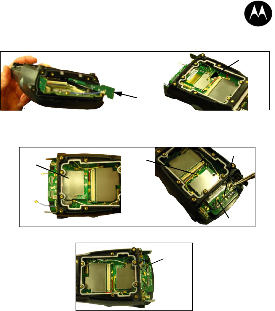
5. Slide the Main antenna into the grooves on the left side of the unit until it is anchored in place. Insert the black
antenna to the socket labelled Black. Route it through the clips to secure it in place. Next, connect the grey GPS
jumper cable as shown.
6. Snap the WAN module onto the hand-held board, making sure to align the module pins with those on the board.
Insert 3 screws torqued to 2.5 in. lbs. Next, insert the yellow Diversity antenna into the socket labelled Yellow.
Connect the grey GPS cable, tucking it under the corner of board as shown. Insert the blue Main antenna into the
socket labelled Blue. Tuck the blue Main antenna under the WAN module shield. The cable should follow the silk
screen routing.
7. Add the fourth screw to secure the WAN module in place.
8. Replace the metal frame, sliding it in from the top. Take care not to damage the cables that have been connected.
Insert the four screws to a torque of 2.5 in. lbs.
9. Install the back cover (x6 screws) and the end-cap (x4 screws). Each is torqued to 2.5 in. lbs.
Main antenna
GPS jumper
cable
WAN module
Yellow diversity
antenna
Blue main
Grey GPS antenna
antenna
Fourth screw
COMPANY HEADQUARTERS SUPPORT SERVICES
Motorola Solutions, Inc. Contact the Motorola Solutions Global Customer Support at:
1301 E. Algonquin Rd. http://www.motorolasolutions.com/support.
Schaumburg, IL 60196-1078, U.S.A.
http://www.motorolasolutions.com