Zebra Technologies AP716102 Mesh AP-7161 Outdoor Wireless Access Point User Manual AP 7161 Access Point Installation Guide
Zebra Technologies Corporation Mesh AP-7161 Outdoor Wireless Access Point AP 7161 Access Point Installation Guide
Contents
- 1. Installation Guide - AP-7161
- 2. User manual
- 3. User Manual
Installation Guide - AP-7161
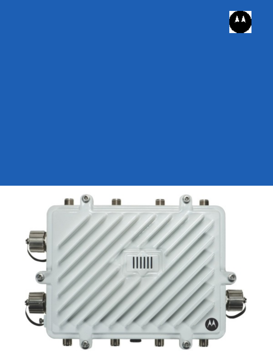
AP-7161
ACCESS POINT
INSTALLATION GUIDE

2 AP-7161 Access Point Installation Guide

AP-7161 Access Point Installation Guide 3
Motorola Solutions reserves the right to make changes to any product to improve reliability, function, or design.
Motorola Solutions does not assume any product liability arising out of, or in connection with, the application or use of any
product, circuit, or application described herein.
No license is granted, either expressly or by implication, estoppel, or otherwise under any patent right or patent, covering or
relating to any combination, system, apparatus, machine, material, method, or process in which Motorola Solutions products
might be used. An implied license exists only for equipment, circuits, and subsystems contained in Motorola Solutions products.
Service Information
If you have a problem using the equipment, contact your facility’s Technical or Systems Support. If there is a problem with the
equipment, they will contact the Motorola Solutions Support at: http://supportcentral.motorola.com.

4 AP-7161 Access Point Installation Guide
Introduction.......................................................................................................................................... 3
Document Conventions........................................................................................................................ 3
Package Contents................................................................................................................................ 4
Hardware Installation........................................................................................................................... 5
Precautions.......................................................................................................................................... 5
Warnings.............................................................................................................................................. 5
Site Preparation................................................................................................................................... 6
Grounding Requirements..................................................................................................................... 6
AP-7161 Grounding Connection.......................................................................................................... 7
Ethernet and Lightning Protection........................................................................................................ 7
Access Point Placement...................................................................................................................... 7
Antenna Options.................................................................................................................................. 8
Installing an AP-7161......................................................................................................................... 10
Required Tools................................................................................................................................... 10
Mounting Bracket Options.................................................................................................................. 10
Extension Bracket.............................................................................................................................. 11
Pole Mounted Installations................................................................................................................. 13
Wall Mounted Installations................................................................................................................. 16
AP-7161 Connections and Ports.........................................................................................................18
Antenna Connectors........................................................................................................................... 18
Console, GE1/POE and GE2 Ports.................................................................................................... 19
Grounding Screw................................................................................................................................ 20
LED Indicators.................................................................................................................................... 21
Three Radio LEDs.............................................................................................................................. 22
Dual Radio LEDs................................................................................................................................ 23
Installing the Power-Over Ethernet (PoE) Unit................................................................................... 24
PoE Unit Specifications...................................................................................................................... 24
PoE Interface Connections................................................................................................................ 25
Installing the PoE Unit........................................................................................................................ 25
Basic AP-7161 Configuration............................................................................................................. 26
Specifications..................................................................................................................................... 26
Regulatory Compliance...................................................................................................................... 30
Country Approvals.............................................................................................................................. 30
Health and Safety Recommendations................................................................................................ 30
Warnings for the Use of Wireless Devices......................................................................................... 30
Potentially Hazardous Atmospheres.................................................................................................. 30
Safety in Hospitals............................................................................................................................. 30
RF Exposure Guidelines.................................................................................................................... 31
Safety Information.............................................................................................................................. 31
Reduce RF Exposure - Use Properly................................................................................................. 31
Remote and Standalone Antenna Configurations.............................................................................. 31
Power Supply..................................................................................................................................... 31
Wireless Devices - Countries............................................................................................................. 31
Country Selection............................................................................................................................... 31
Operation in the US............................................................................................................................ 31

AP-7161 Access Point Installation Guide 5
Radio Frequency Interference Requirements - FCC.......................................................................... 31
Radio Transmitters (Part 15).............................................................................................................. 32
Radio Frequency Interference Requirements - Canada..................................................................... 32
Radio Transmitters............................................................................................................................. 32
CE Marking and European Economic Area (EEA)............................................................................. 32
Statement of Compliance................................................................................................................... 32
Japan (VCCI) - Voluntary Control Council for Interference................................................................ 32
Korea Warning Statement for Class B............................................................................................... 33
Other Countries.................................................................................................................................. 33
Waste Electrical and Electronic WEEE.............................................................................................. 35
Motorola’s Enterprise Mobility Support Center................................................................................... 36
AP-7161 Series ROHS Compliance................................................................................................... 37

6 AP-7161 Access Point Installation Guide
AP-7161 Access Point Installation Guide 7
Introduction
The AP-7161 is a wireless broadband data system that uses mesh networking technology to support broadband data coverage.
The system offers both 2.4 GHz 802.11b/g/n and 5.x GHz 802.11n Wi-Fi client access with 2.4 GHz 802.11 b/g/n and 5.x GHz
802.11a/n meshing. The dual-band system supports industry standard client devices and features easily deployed fixed
infrastructure nodes.
The AP-7161 is also designed to extend the network with outdoor deployments. Deployments can be managed using the
Motorola Solutions WiNG 5 architecture. The WiNG 5 architecture is a solution designed for 802.11n networking. It leverages
the best aspects of independent and dependent architectures to create a smart network that meets the connectivity, quality and
security needs of each user and their applications, based on the availability of network resources, including wired networks.
WiNG 5 is a Third Generation WLAN solution – taking the best of both the first generation Autonomous access point WLAN and
the second generation Centralized Controller Based WLAN.
The control plane is now distributed between the access points and the controllers. The network administrator has the flexibility
of directing the data plane either being forwarded directly from the access points, or via the controllers. By distributing
intelligence and control between the wireless controllers and APs, the WiNG 5 network can route directly via the best path, as
determined by factors including the user, the location, the application and the available wireless and wired resources.
Once adopted by a Motorola Solutions RFS4000, RFS6000 or RFS7000 series controller, the AP-7161 is managed as an
Adaptive AP running the WiNG 5 network management protocol. Motorola Solutions WiNG 5 Networks extend the differentiation
that Adaptive APs offered to the next level by having the services and security now available at every point in the network. The
traffic flow is optimized to prevent wired congestion as well as wireless congestion. Traffic flows dynamically, based on user and
application, and finds alternate routes to work around any possible network choke points. Mixed-media application optimization
is the hallmark of WiNG 5 networks.
For the latest version of this guide go to:http://support.symbol.com/support/product/manuals.do
Document Conventions
The following graphical alerts are used in this document to indicate notable situations.AP-7161
.
NOTE Tips, hints, or special requirements that you should take note of.
CAUTION Care is required. Disregarding a caution can result in data loss or equipment
malfunction.
WARNING! Indicates a condition or procedure that could result in personal injury or
equipment damage.

8 AP-7161 Access Point Installation Guide
Package Contents
Carefully remove all protective material from around the AP-7161 and save the shipping container for later storage and shipping.
Verify that you received the equipment listed below:
• AP-7161 access point
• Weatherproof RJ45 plug kit
• AP-7161 Access Point Installation Guide
Inspect the equipment for damage. If you are missing any equipment or if you find any damaged equipment, contact the
Motorola Solutions Support immediately.
AP-7161 Access Point Installation Guide 9
Hardware Installation
The AP-7161 access point has the following port designations:
• GE1/POE - LAN Port
• GE2 - WAN Port
• Console Port
An AP-7161 must be installed by trained professionals familiar with RF planning and regulatory limits defined by the regulatory
bodies of the country where the devices are being deployed. All common precautions for grounding and ESD (Electrostatic
Discharge) protection should be observed during deployment and installation. AP-7161 devices must be installed such that no
harmful interference results from device operation.
Precautions
Before installing an AP-7161 model access point verify the following:
• Become familiar with all grounding requirements (see Installing an AP-7161 on page 14)
• The grounding cable for an AP-7161 must be a #10 gauge wire cross section. The cable can be attached to the unit using
one of the three recommended methods:
•Loosen the grounding screw, insert the grounding cable into the hole below it and tighten the screw.
•Loosen the grounding screw, wind the grounding cable around and tighten the screw.
•Attach a ring lug to the grounding cable and secure it to the unit using the grounding screw.
• Verify that the deployment environment has a continuous temperature range compatible with the operating temperature
range of the device.
Warnings
• Read all installation instructions and site survey reports, and verify correct equipment installation before connecting the
access point to its power source.
• Remove jewelry and watches before installing this equipment.
• Verify that the unit is grounded before connecting it to the power source.
• Verify that any device connected to this unit is properly wired and grounded.
• Connect all power cords to a properly wired and grounded electrical circuit. Verify that the electrical circuits have appropriate
overload protection.
• Attach only approved power cords to the device.
• Verify that the power connector and socket are accessible at all times during the operation of the equipment.
CAUTION All device wiring must comply with the National Electric Code (NEC) or
regulations and procedures defined by the regulatory bodies of the country or
region where the devices are being deployed. All local building and structure
codes must be observed.
WARNING! Strictly observe the following Safety Warnings and Precautions when installing
an AP-7161 access point.

10 AP-7161 Access Point Installation Guide
• Do not hold any component containing a radio such that it is very close to or touching any exposed parts of the body,
especially the face or eyes, while transmitting.
• Do not work with power circuits in dimly lit spaces.
• Do not install this equipment or work with its power circuits during thunderstorms or other weather conditions that could
cause a power surge.
• Verify there is adequate ventilation around the device, and that ambient temperatures meet equipment operation
specifications.
• Avoid contact with overhead power lines.
• Take precautions to avoid injury from falling tools and equipment. Crews should wear hard hats in and around the installation
work site.
• Be aware of vehicular traffic in and around the installation work site.
• Do not operate a portable transmitter near unshielded blasting caps or in an environment where explosives are present
unless the transmitter is especially certified for such use.
Site Preparation
• Consult your site survey and network analysis reports to determine specific equipment placement, power drops, and so on.
• Assign installation responsibility to the appropriate personnel.
• Identify and document where all installed components are located.
• Identify and prepare Ethernet and console port connections.
• Verify that cable lengths are within the maximum allowable distances for optimal signal transmission.
Grounding Requirements
To avoid damage to the equipment, become familiar with Motorola Solutions Policy R56 before installing AP-7161 units. Refer
to Standards and Guidelines For Communication Sites, Version B. Both the hardcopy manual (Part Number 68P81089E50-B)
and the CD version (Part Number 9880384V83) can be ordered from Motorola Solutions.
Section 7.6.4 Broadband - Wireless Access Point Network from the Standards and Guidelines For Communication
Sites applies directly to AP-7161 deployments: SPD (Surge Protection Device) considerations for broadband shall include the
use of SPDs to protect pole-mounted access points and ground-based cabinet architecture. It is important to install proper SPD
applications on both ends of Ethernet, Power-Over Ethernet (POE), Giga-Ethernet (GigE) and AC cable runs. SPDs shall be
located within the node or cabinet, or as close to the entrance as possible, and properly installed into load centers, control
panels and utility power cabinets. While RF protection is a consideration, it shall only be required when antennas are connected
to the node with coaxial cables greater than 610 mm (2 ft.) in length.
Lightning protection should be used on all shielded CAT-5E Ethernet connections.
An outdoor rated Lightning Protection Unit (LPU) kit such as the Motorola Solutions PTP WB2978AA or the HyperLink
AL-CAT6HPJW Lightning Protector should be used.
NOTE Lightning damage is not covered under the conditions of a standard Motorola Solutions product
warranty. When installed correctly, LPUs provide the best protection from the harmful effects of
lightning. Observe all regional and national codes that apply for lightning protection.
AP-7161 Access Point Installation Guide 11
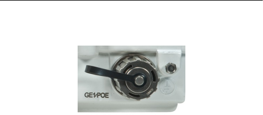
AP-7161 Grounding Connection
The grounding cable for an AP-7161 must be a #10 gauge wire cross section.The grounding screw is located to the right of the
GE1/POE port above the ground symbol.
The cable can be attached to the unit using one of the three recommended methods:
•Loosen the grounding screw, insert the grounding cable into the hole below it and tighten the screw.
•Loosen the grounding screw, wind the grounding cable around and tighten the screw.
•Attach a ring lug to the grounding cable and secure it to the unit by tightening the grounding screw.
When connecting the grounding cable to the unit, use an 8mm Socket and driver to tighten the grounding screw to between 21.9
and 29.2 inch pounds (lbf-in).
Ethernet and Lightning Protection
When installing an AP-7161, lightning protection should be used on all Shielded CAT-5E Ethernet connections. An outdoor rated
Lightning Protection Unit (LPU) kit such as the Motorola Solutions PTP WB2907AA or the HyperLink AL-CAT6HPJW Lightning
Protector should be used. For more information on Motorola Solutions PTP Lightning Protection Unit, refer to the PTP-LPU
Technical Specifications.
Access Point Placement
Observe the following recommended guidelines to help ensure a successful network deployment:
• Mount the device with the black gore vent down.
• Mounting height for network devices should not exceed 30 to 35 feet. Mounting height should vary to accommodate the
topography of the deployment area, foliage, and other obstructions.
• Devices can be deployed using any of the recommended outdoor Deployment Procedures.
• Line of sight (LoS) guidelines should be given special consideration whenever devices will not be installed in a straight line,
such as deploying devices on alternating sides of a roadway.
12 AP-7161 Access Point Installation Guide
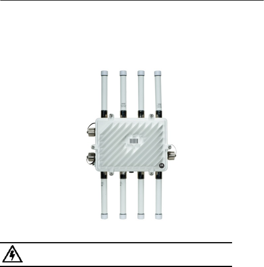
Antenna Options
Motorola Solutions supports two antenna suites for AP-7161 access points, one suite supporting the 2.4 GHz band and another
suite supporting the 5 GHz band. Select a model best suited to the intended operational environment of your access point. The
AP-7161 model access point can be purchased in a three radio configuration. If a three radio unit is purchased, the access point
ships with two dual-band radios that should be connected to ports R3-A and R3-B. This is in addition to the other six antennas
available to the access point’s other two radios. The single antenna supporting the third radio supports sensor mode only and
can not function as a WLAN radio.
WARNING! Antenna ports where no antenna is mounted must be properly terminated using
an approved IP 67 terminator.

AP-7161 Access Point Installation Guide 13
The AP-7161 antenna suite includes the following models:
Antenna Description Band Gain Height
(in/mm) P/N
2,4 GHz, fixed DP, Omni, 80 dBi, Type N-M 2.4 8 19.5/495 ML-2499-FHPAG8-01
5.4 GHz, fixed DP, Omni, 10 dBi, Type N-M 4.9-5.8. 10 19.5/495 ML-5299-FHPAG10-01
Dual Band WIPS antenna 2.4, 5.2-5.8 4.5-7.5 11/280 ML-2452-HPAG5A8-01-01
4.9-5.9 GHz, fixed DP, 6 dBi,Type N-M 4.9-5.8 7.5 11/280 ML-5299-FHPA6-01R
2.4 GHz, fixed DP, 5DBI,Type N-M 2.4 5 - ML-2499-FHPA5-01R
2.4 GHz, downtilt 8 dBi, Type N-M 2.4 8 21/533 RAN4054A
14 AP-7161 Access Point Installation Guide
Installing an AP-7161
The following guidelines and procedures should be observed when installing an AP-7161:
Required Tools
The following is a list of the minimal tool set required to install an AP-7161:
• 8 mm socket and driver
• Torque wrench or ratchet with 10mm, 1/2 inch and 3/4 inch sockets.
• Adjustable wrench
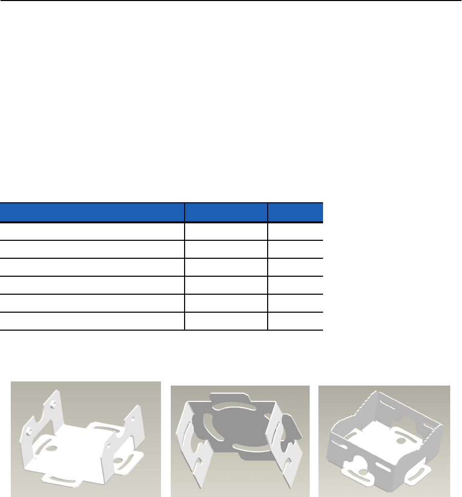
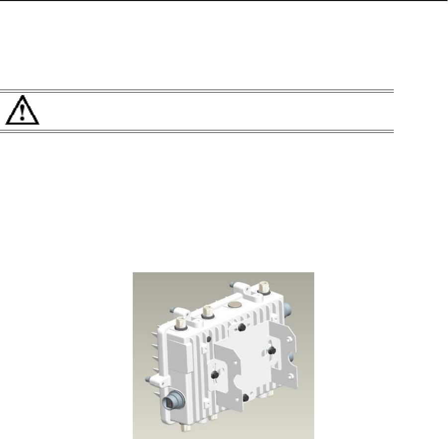
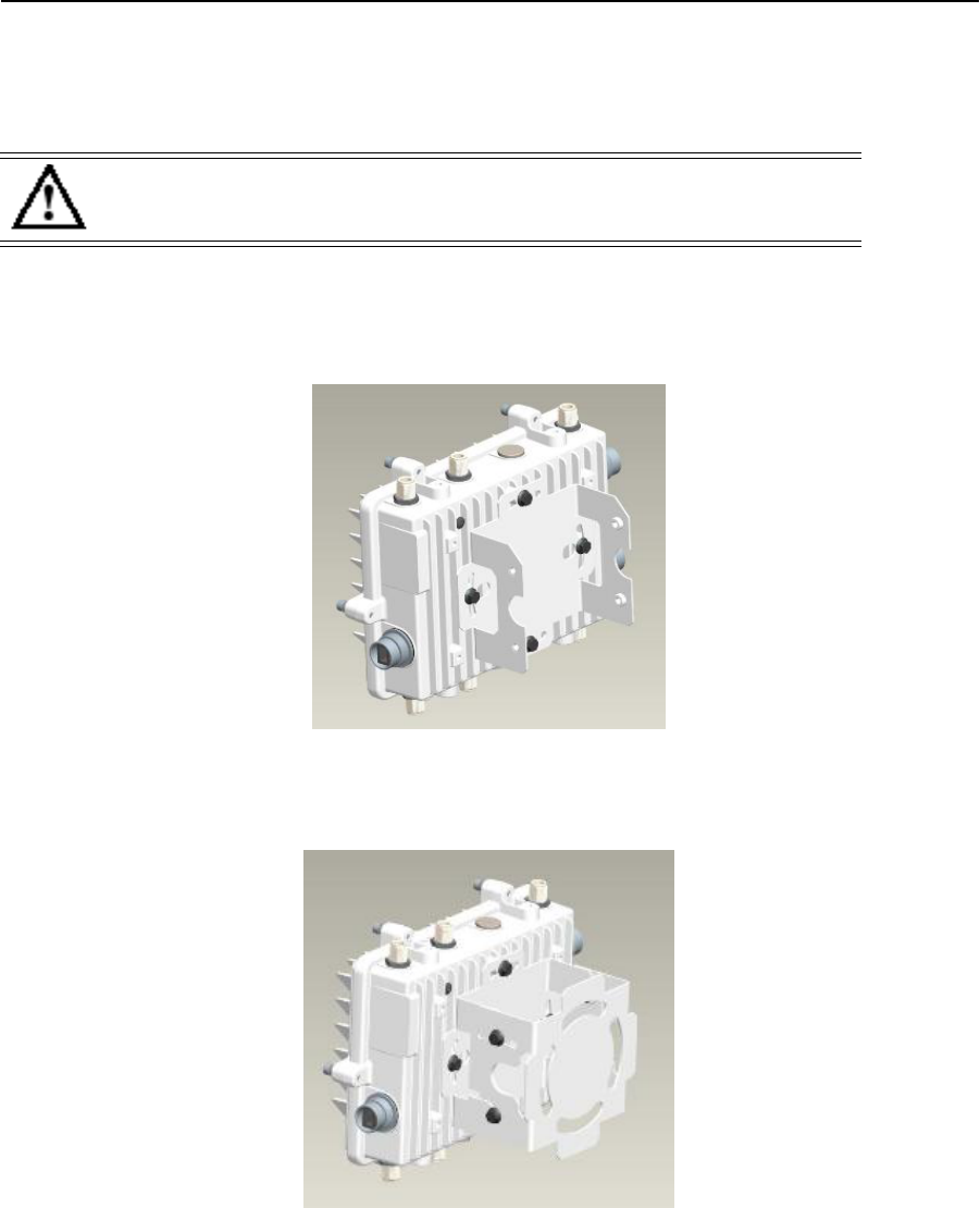
Mounting Bracket Options
The mounting bracket kit and extension mounting hardware for the AP-7161 support several options for installation.
The AP-7161 mounting bracket kit contains:
The three individual sections for the AP-7161 mounting bracket kit (P/N SKJC120210-001, -002 and -003) can be adjusted to
rotate (plus or minus 15 degrees) and tilt (up to 45 degrees) during installation to orient the unit for optimum positioning.
Description Part Number Quantity
Mounting bracket section 1 SKJC120210-001 1
Mounting bracket section 2 SKJC120210-002 1
Mounting bracket section 3 SKJC120210-003 1
Serrated hex flanged screw, M6 x1.0 x 12 SKJC120210-004 8
Hex nut, 1/2inch - 13 thread SKJC120210-006 4
Hex head bolt, 1/2 inch - 13 thread x 3/4 inch SKJC120210-007 2
AP-7161 Access Point Installation Guide 15
Assembly of the complete mounting bracket is shown below.
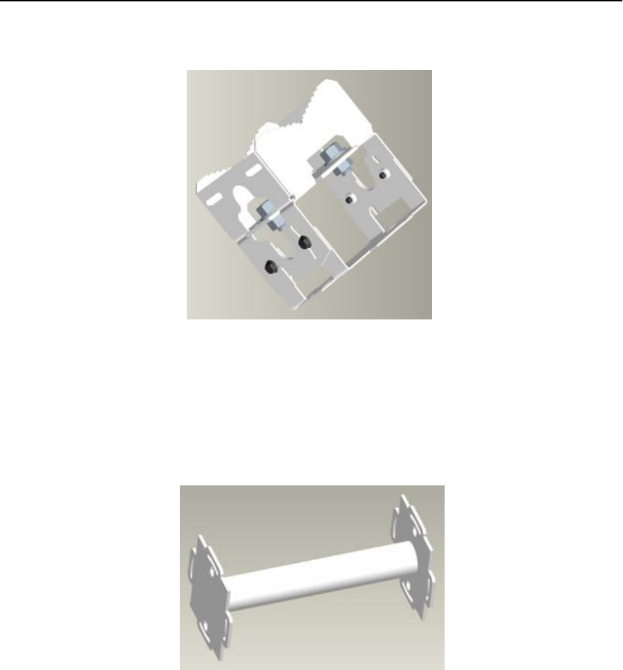
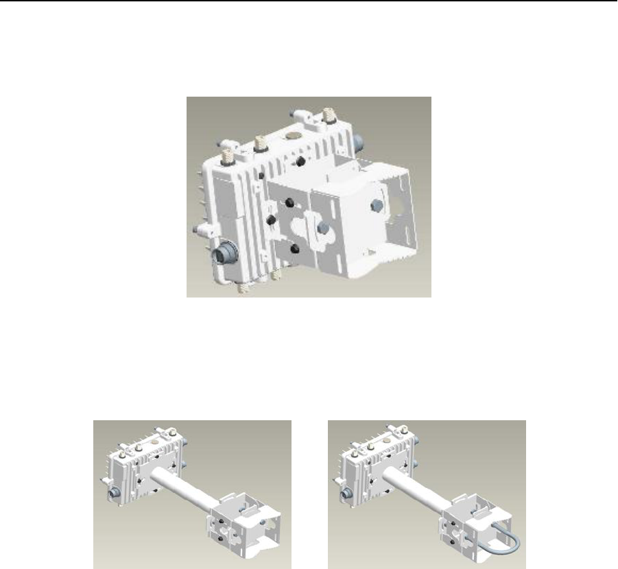
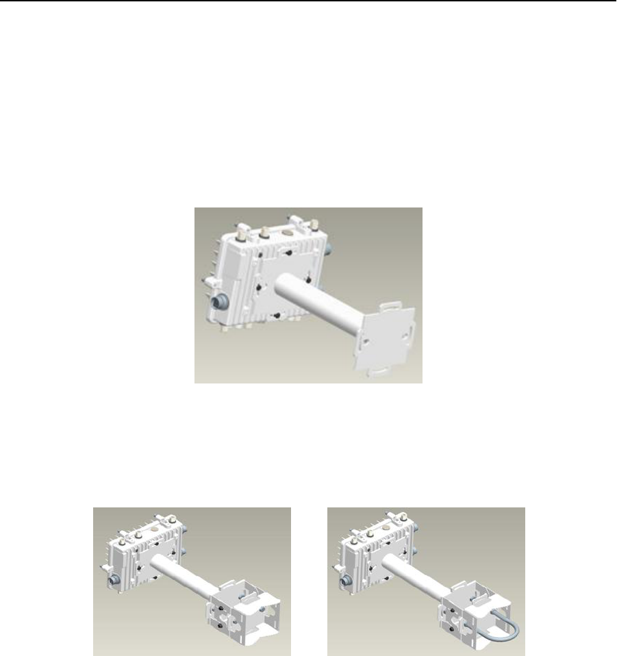
Extension Bracket
When mounting an AP-7161 on poles more than six inches in diameter, a minimum standoff distance of twelve inches is
required to avoid interference with the antennas. The extension bracket (P/N SKJC032811) can be used in combination with the
standard mounting bracket when required.
16 AP-7161 Access Point Installation Guide
The extension bracket can be used alone, or in combination with parts of the mounting bracket.
AP-7161 Access Point Installation Guide 17
Pole Mounted Installations
The mounting bracket kit and extension can be used in various combinations to properly install the AP-7161 on a pole. For poles
of up to 3 inches in diameter, attach SKJC120210-003 at the desired position on the pole using a 1/2 inch U-bolt and nuts (not
included in the mounting bracket kit).
For poles up to 3 inches in diameter:
1. Thread the two outer nuts onto the U-bolt. Place the U-bolt at the desired mounting location.
2. Place the SKJC120210-003 bracket section on the U bolt. Adjust the nuts until the bracket section is against the pole and the
U-bolt can be secured tightly to the pole by.
3. Put the two inner nuts on the U-bolt to securely attach the mounting bracket section. Adjust the nuts until the U-bolt and the
bracket section are securely attached to the pole
4. Tighten the nuts to 70 inch pounds (lbf-in).
5. Using a torque wrench or a ratchet and a 10mm socket, attach (but don’t tighten) SKJC120210-001 to the access point with
four M6 hex flange screws.
6. Using a torque wrench or a ratchet and a 10mm socket, attach (but don’t tighten) SKJC120210-001 to SKJC120210-001 with
four M6 hex flange screws.
7. To adjust the position of the access point, rotate SKJC120210-001 (plus or minus 15 degrees) and tilt SKJC120210-002 (up
to 45 degrees).
CAUTION Always mount the AP-7161 with the black gore vent facing down.

18 AP-7161 Access Point Installation Guide
8. Tighten all hex flange screws to 9 inch pounds (lbf-in).
For poles greater than 3 inches in diameter:
1• Attach SKJC120210-003 to the pole using band clamps.
2. Using a torque wrench or a ratchet and a 10mm socket, attach (but don’t tighten) SKJC120210-001 to the access point with
four M6 hex flange screws.
3. Attach SKJC120210-002 to SKJC120210-003 using two 1/2 inch bolts and nuts. Tighten the nuts to 70 inch pounds (lbf-in).
AP-7161 Access Point Installation Guide 19
4. Using a torque wrench or a ratchet and a 10mm socket, attach (but don’t tighten) SKJC120210-001 to SKJC120210-001 with
four M6 hex flange screws.
5. To adjust the position of the access point, rotate SKJC120210-001 (plus or minus 15 degrees) and tilt SKJC120210-002 (up
to 45 degrees).
6. Tighten all hex flange screws to 9 inch pounds (lbf-in).
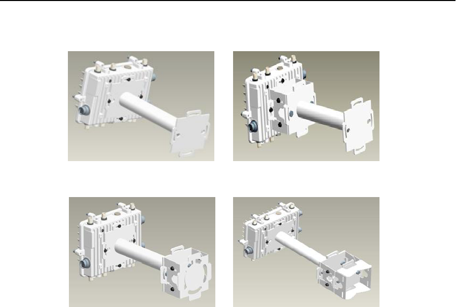
Examples for using the extension bracket alone, or with the mounting bracket for a pole mount installation are shown below.
To use the extension bracket:
1• Using a torque wrench or a ratchet and a 10mm socket, attach the extension bracket to the access point with four M6 hex
flange screws. Tighten the hex flange screws to 9 inch pounds (lbf-in).
2. Attach the extension bracket to SKJC120210-001 of the assembled mounting bracket using two 1/2 inch bolts and nuts.
Tighten the nuts to 70 inch pounds (lbf-in).
20 AP-7161 Access Point Installation Guide
Wall Mounted Installations
For wall mounted installations, use P/N SKJC120210-001 and -002.
1• Using four #10/32 lag bolts, attach SKJC120210-002 at the desired mounting location.
2. Using a torque wrench or a ratchet and a 10mm socket, attach (but don’t tighten) SKJC120210-001 to the access point with
four M6 hex flange screws.
3. Using a torque wrench or a ratchet and a 10mm socket, attach (but don’t tighten) SKJC120210-001 to SKJC120210-002 with
four M6 hex flange screws.
CAUTION Always mount the AP-7161 with the black gore vent facing down.
AP-7161 Access Point Installation Guide 21
4. To adjust the position of the access point, rotate SKJC120210-001 (plus or minus 15 degrees) and tilt SKJC120210-002 (up
to 45 degrees).
5. Tighten all hex flange screws to 9 inch pounds (lbf-in).
Examples of options for using the extension bracket alone or with the mounting bracket for a wall mount installation are shown
below.hex
To use only the extension bracket:
1• Using four #10/32 lag bolts, attach SKJC120210-002 at the desired mounting location.
2. Using a torque wrench or a ratchet and a 10mm socket, attach the extension bracket to the access point with four M6 hex
flange screws. Tighten the hex flange screws to 9 inch pounds (lbf-in).
To use the extension bracket with the mounting bracket:
1• Using a torque wrench or a ratchet and a 10mm socket, attach the extension bracket to the access point with four M6 hex
flange screws. Tighten the hex flange screws to 9 inch pounds (lbf-in).
2. Attach the extension bracket to SKJC120210-001of the assembled mounting bracket already in position using two 1/2 inch
bolts and nuts. Tighten the nuts to 70 inch pounds (lbf-in).
22 AP-7161 Access Point Installation Guide
AP-7161 Connections and Ports
This section shows the connections and ports on the AP-7161 access point.
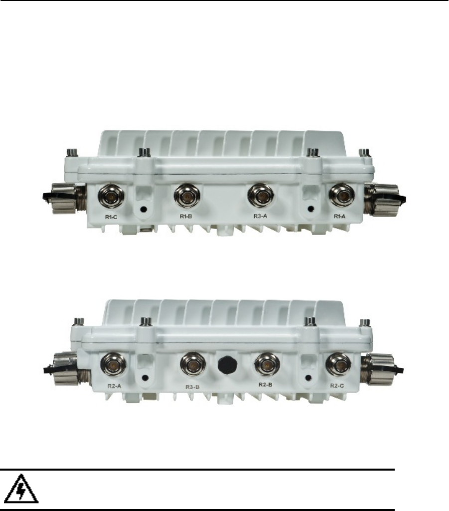
Antenna Connectors
The AP-7161 is configured with eight N type male connectors to support two or three active radios.
Mount the 2.4 GHz antennas on the connectors marked R1-A, R1-B and R1-C.
Mount the 5 GHz antennas on the connectors marked R2-A, R12-B and R2-C.
The optional Dual Band antennas can be mounted on the connectors marked R3-A and R3-B.
WARNING! Antenna ports where no antenna is mounted must be properly terminated using
an approved IP67 terminator.
AP-7161 Access Point Installation Guide 23
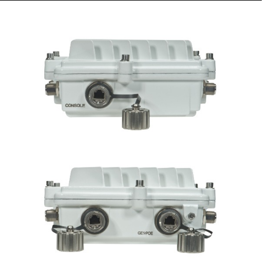
Console, GE1/POE and GE2 Ports
The AP-7161 has Ethernet ports for external Console, GE1/POE, and GE2 connections.
When making connections using these ports, a properly rated RJ45 connector is required. One Weatherproof RJ45 plug kit is
provided with each access point. When connecting cables to the AP-7161 Ethernet ports, follow the instructions in the connector
packaging and tighten the connectors to create a weatherproof seal. Shielded cables are required.
24 AP-7161 Access Point Installation Guide
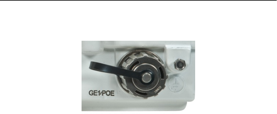
Grounding Screw
The grounding screw is located to the right of the GE1/POE port and above the GND symbol.
The grounding cable for an AP-7161 must be a #10 gauge wire cross section. The cable can be attached to the unit using one
of the three recommended methods:
•Loosen the grounding screw, insert the grounding cable into the hole below it, and tighten the screw.
•Loosen the grounding screw, wind the grounding cable around the screw, and tighten the screw.
•Attach a ring lug to the grounding cable and remove the grounding screw to attach the ring lug to the access point. Secure
it to the unit by tightening the grounding screw.
When connecting the grounding cable to the unit, use an 8mm Socket and driver to tighten the grounding screw to between 21.9
and 29.2 inch pounds (lbf-in).
AP-7161 Access Point Installation Guide 25
LED Indicators
The AP-7161 has six LEDs on the top of the access point housing.
The access point utilizes two (different colored) lights below each LED. Only one light displays within a LED at any given time.
Every light within each LED is exercised during startup to allow the user to see if an LED is non-functional. The LEDs turn on
and off while rotating around in a circle. Since two LEDs feed each light pipe, the pattern is from left to right, then right to left.

26 AP-7161 Access Point Installation Guide
The top housing LEDs have the following display and functionality:
Three Radio LEDs
A three radio access point has the following unique LED behavior:
LED 1 LED 2 (LAN) LED 3 (WAN) LED 4 - 5 GHz LED 5 - 2.4 GHz LED 6
Blinking Red
indicates
booting. Solid
Red defines the
diagnostic
mode.
White defines
normal
operation.
Green defines
normal GE1
operation.
Green defines
normal GE2
operation.
Blinking
Amber
indicates
802.11a activity.
A 5 second
Amber and
Yellow blink
rate defines
802.11an
activity.
A 2 second
Amber and
Yellow blink
rate defines
802.11an
(40 MHz)
activity.
When
functioning as a
sensor, LED
alternates
between
Amber and
Yellow.
The blink
interval is 0.5
seconds. It’s 1
second when no
Server is
connected.
Blinking
Emerald
indicates
802.11bg
activity.
A 5 second
Emerald and
Yellow blink
rate defines
802.11bgn
activity.
A 2 second
Emerald and
Yellow blink
rate defines
802.11bgn
(40 MHz)
activity.
When
functioning as a
sensor, LED
alternates
between
Emerald and
Yellow.
The blink
interval is 0.5
seconds. It’s 1
second when no
Server is
connected.
Blinking
Emerald
indicates the
radio is
defined as a
sensor, but is
disabled.
Alternates
between
Emerald and
Amber when
the radio is
defined as a
sensor with
no Server
connected.
The blink
interval is
1 second.
Alternates
between
Emerald and
Amber when
the radio is
defined as a
sensor and a
Server is
connected.
The blink
interval is
0.5 seconds.

AP-7161 Access Point Installation Guide 27
Dual Radio LEDs
A dual radio model access point has the following unique LED behavior:
LED 1 LED 2 (LAN) LED 3 ((WAN) LED 4 - 5 GHz LED 5 - 2.4 GHz LED 6
Blinking Red
indicates
booting. Solid
Red defines the
diagnostic
mode.
White defines
normal
operation.
Green defines
normal GE1
operation.
Green defines
normal GE2
operation.
Blinking
Amber
indicates
802.11a activity.
A 5 second
Amber and
Yellow blink
rate defines
802.11an
activity.
A 2 second
Amber and
Yellow blink
rate defines
802.11an
(40 MHz)
activity.
When
functioning as a
sensor, LED
alternates
between
Amber and
Yellow.
The blink
interval is 0.5
seconds. It’s 1
second when no
Server is
connected.
Blinking
Emerald
indicates
802.11bg
activity.
A 5 second
Emerald and
Yellow blink
rate defines
802.11bgn
activity.
A 2 second
Emerald and
Yellow blink
rate defines
802.11bgn
(40 MHz)
activity.
When
functioning as a
sensor, LED
alternates
between
Emerald and
Yellow.
The blink
interval is 0.5
seconds. It’s 1
second when no
Server is
connected.
Not Used
28 AP-7161 Access Point Installation Guide
Installing the Power-Over Ethernet (PoE) Unit
The AP-7161 can be powered by a standalone Gigabit PoE injector or from a Motorola Solutions LAN controller. A standard
CAT5E cable can be used to provide the connection. When connecting to the GE1/POE port on the AP-7161, you must use the
weatherproof RJ-45 plug kit that comes with the unit and it must be properly installed to maintain a weatherproof seal.
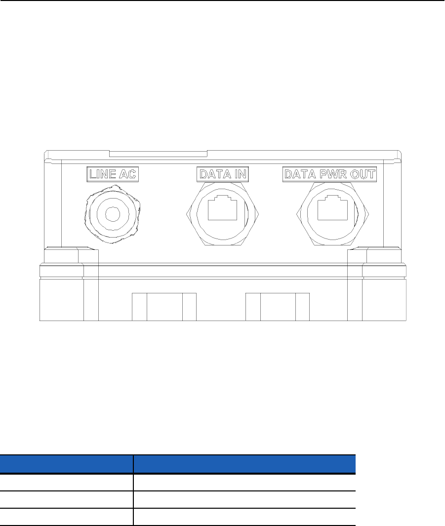
The recommended Power-Over Ethernet (PoE) device for AP-7161 outdoor deployments.is the PowerDsine 9001GO, 1-Port
802.3at Gigabit device. If the recommended Motorola Solutions outdoor Gigabit PoE injector is used, a weatherproof plug is
provided for connecting the CAT5E cables. The port labeled DATA PWR OUT is used for the connection to the AP-7161. The
port labeled DATA IN is used for the connection to the wired network. If the CAT5E cable used to connect the wired network and
the PoE injector has to travel though a building egress, a suitable lightning protection system must be deployed (see AP-7161
Grounding Connection on page 11).
The device injects power over data-carrying Ethernet cabling. It maintains the IEEE802.3at and IEEE802.3af standard. These
power levels allow usage by a new range of Ethernet-based applications, such as video phones, 802.11n access points, WiMAX
Transmitters, PTZ cameras and more. The PD-9001GO DATA PWR OUT port is designed to carry Gigabit Ethernet data &
power over a standard CAT5E cable, delivered through 2-pairs (Alt B: pins 4,5 (+) and 7,8 (-)).
The DATA IN and DATA PWR OUT ports on the recommended Power-Over Ethernet (PoE) device for AP-7161 outdoor
deployments are shielded RJ45 data sockets. They cannot be used as plain old telephone service (POTS) telephone sockets.
Only RJ45 data connectors can be connected to these sockets.
PoE Unit Specifications
Parameter Description
Input Voltage 100-240 VAC (50-60 Hz)
Input Current 1 Ampere (maximum)
Maximum Available Output Power 30 Watts
AP-7161 Access Point Installation Guide 29
PoE Interface Connections
Installing the PoE Unit
When making connecting the PoE unit to the AP-7161 GE1/POE port, a properly rated RJ45 connector is required. Tighten the
connectors to create a weatherproof seal.
To connect the PoE unit to the access point:
1• Connect the DATA IN jack to the GE1/POE connector.
2. Connect the PoE unit to a 100-240 VAC outlet.
To mount the PoE Unit:
1• Mount the unit as required for an AP-7161 pole or wall mount installation.
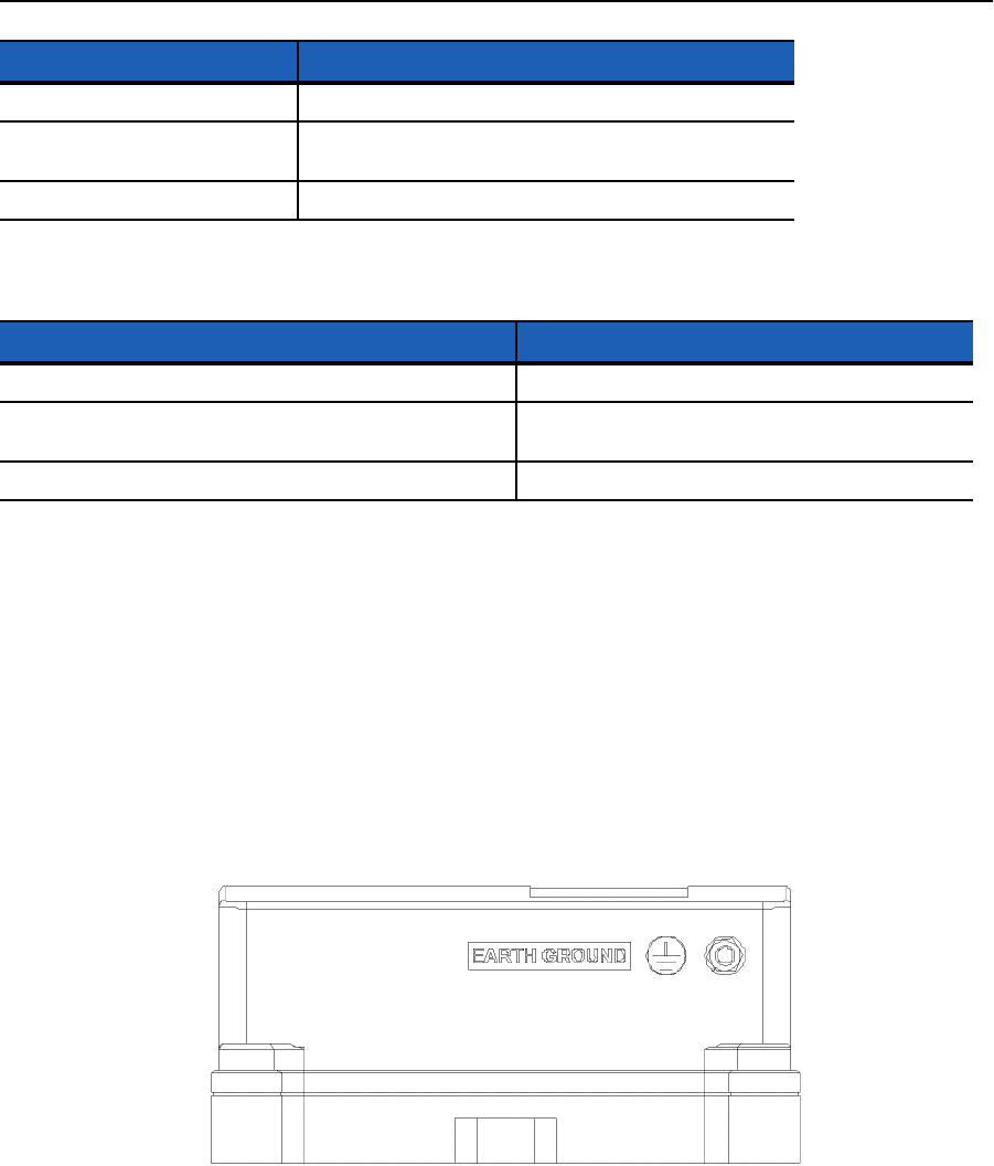
2. Connect the earth ground cable to the unit and properly connect the cable to an external ground.
Nominal Output Voltage 54 to 57 VDC
Operating Temperature -40 to -55 degrees C / -40 to 131 degrees F for 30 Watts
-40 to -65 degrees C / -40 to 149 degrees F for 15.4 Watts
Storage Temperature -20 to 85 degrees C / -40 to -185 degrees F
Port Connector
Input (Data In) Ethernet 10/100/1000Base T RJ45 female socket
Output (DATA PWR OUT) Ethernet 10/100/1000Base T, +55 VDC RJ45 female socket
with DC voltage on wire pairs 1-2, 3-6, 4-5 and 7-8.
Power cable Pre-installed 5m power cable with main plug.
Parameter Description

30 AP-7161 Access Point Installation Guide
The AP-7161 can also be connected directly to a Motorola Solutions controller if it is located within 100 meters of the controller
and a PoE port is available. If the CAT5E cable used to connect the radio and the controller has to travel though a building
egress, a suitable lightning protection system must be deployed (see Ethernet and Lightning Protection on page 11).
When using controllers, the total power limits for the AP-7161 must be considered. The two radio configuration draws less power
than a three radio configuration. If insufficient power is available, the software will disable the third radio and throttle back
performance on all radio and Ethernet interfaces.
Basic AP-7161 Configuration
The AP-7161 access point receives its configuration once adopted by a Motorola Solutions RFS4000, RFS6000 or RFS7000
series controller. There are no required initial configuration settings beyond verifying power and LED functionality for the access
point. Once adopted, the access point is managed by its connected controller and can receive periodic firmware updates when
Motorola Solutions releases updates with new controller functionality.
For information on how use a Motorola Solutions RFS Series controller to manage an AP-7161 access point, refer to
http://support.symbol.com/support/product/manuals.do.
Specifications
Hardware Specifications
Operating Voltage 36-57 VDC
Operating Current Not to exceed 750 mA@48 VDC
Power In (PoE) PoE support inbound power - 802.3AT on GE1/POE port
Unit Dimensions (mounted) 32cm W x 22.5cm H x 10cm D
Unit Weight 6.4 lbs / 2.9 Kg
Mounting Adaptable mounting kit for pole and wall deployments with optional extension arm accessory
LED 6 top mounted weatherized LEDs with multi function read
Uplink 2 Gigabit Ethernet Ports (GE1/POE, GE2) autosensing
Antenna Connectors Outdoor rated N-Type connectors
Console Port Outdoor rated RJ45 console port
Hardware Reset External hardware reset button
Multi Band Security Sensor Outdoor 27x7 Wireless Intrusion Prevention System (IPS) Sensor
(Part number AP-7161-66S40-INTL, AP-7161-66S40-US)

AP-7161 Access Point Installation Guide 31
Environmental Specifications
Radio Specifications
* Transmit power may vary based on local standards for the area of deployment.
Operating Temperature -40 to +70 degrees celsius
Storage Temperature -40 to +85 degrees celsius
Operating Humidity 5-100 percent
Operating Altitude 8,000 feet
Storage Altitude 30,000 feet
Electrostatic Discharge (ESD) Outdoor IP67 rated, corrosion resistant enclosure
ASTM B117 salt, fog, and rust resistance
Wind Ratings 150 mph * (unit bracket measurement)
Operational Shock IE60721-3-4, Class 4M3, MIL STD 810F
Operational Vibration IE60721-3-4, Class 4M3
Network Standards IEEE 802.11 a/b/g/n, 802.11e, 802.11i, WPA2, WMM, and WMM-UAPSD
Supported Data Rules 802.11b/g :1, 2, 5.5, 11, 6, 9, 12, 18, 24, 36, 48 and 54 Mbps
802.11a : 6, 9, 12, 18, 24, 36, 48 and 54 Mbps
802.11n : MCS 0-15 up to 300 Mbps
802.11n Support 3x3 MIMO with 2 spatial streams
20MHz and 40MHz channels supported
300Mbps data rates per radio
Packet aggregation (AMSDU,AMPDU)
Reduced interframe spacing
802.11 b/g/n Operating frequency 2.4 - 2.483 GHz
Maximum AP Transmit Power 25 dBm*
802.11 a/n Operating frequency 4.9 GHz - 4.990 GHz and 5.25 Ghz - 5.35 Ghz and 5.470 GHz - 5.825 GHz
Maximum AP transmit power 26 dBm*

32 AP-7161 Access Point Installation Guide
Networking and Software Specifications
Certification and Safety Specifications
* For more country specific regulatory information please contact Motorola Solutions.
Software Platform WiNG 5.X Platform AP
Security Stateful Firewall, IP filtering, NAT, 802.1X, 802.11i WPA2, WPA
24x7 Dual band sensor capabilities * (subject to software license keys and sensor radio SKU)
Advanced forensics
Connectivity troubleshooting
Wireless Intrusion Prevention
LiveRF
On board IDS and secure guest hotspot access
Quality of Service (QoS) WMM, WMM-UAPSD, 802.1p, Diffserv and TOS
Routing Layer 3 routing, 802.1q/p, DynDNS, DHCP server/client, BOOTP Client, PPPoE and LLDP
Unit Weight 6.4 lbs / 2.9 Kg
Mounting Mounting kit for pole and wall deployments with optional extension arm accessory
LED 6 top mounted weatherized LEDs with multi function read
Uplink 2 gigabit Ethernet ports (GE1/POE, GE2) autosensing
Antenna Connectors Outdoor rated N-Type connectors
Console Port Outdoor rated RJ45 console port
Hardware Reset External hardware reset button
Multi Band Security Sensor Outdoor 27x7 wireless intrusion prevention system (IPS) sensor
(Part Number AP-7161-66S40-INTL, AP-7161-66S40-US)
Radio* FCC Title 47, part 15, part 90
EN 301 489-17
EN 301 893 v1.5.1 DFS
EN 302 502 DFS
EN 300 328
Industry Canada
China SRRC
Australia/New Zealand
Safety* UL 60950-1, -22
CSA C22.2 No.60950-1-07, -22
CB-IEC 60950 -1, 22
EN 60950-1:2006+ A11:2009
RoHS/WEE/CMM
CE

AP-7161 Access Point Installation Guide 33
Optional Accessories
• Mounting kit
• Extension arm for mounting kit
• IP66 outdoor rated 802.3AT power injector
• Mounting kit for outdoor IP 66 802.3AT power injector
• External antenna options
Warranty
• One (1) year on AP-7161 hardware (accessories not included)
• (30) day on accessories
• (90) day on software

34 AP-7161 Access Point Installation Guide
Regulatory Compliance
This device is approved under the Symbol Technologies, Inc. brand. Symbol Technologies, Inc. is a wholly owned subsidiary of
Motorola Solutions, Inc. (collectively “Motorola”).
All Motorola Solutions devices are designed to be compliant with rules and regulations in locations they are sold and will be
labeled as required. Any changes or modifications to Motorola Solutions equipment, not expressly approved by Motorola
Solutions, could void the user's authority to operate the equipment.
Local language translations are available at the following website:
http://supportcentral.motorola.com/
Motorola Solutions devices are professionally installed, the Radio Frequency Output Power will not exceed the maximum
allowable limit for the country of operation.
Antennas: Use only the supplied or an approved replacement antennas. Unauthorized antennas, modifications, or attachments
could cause damage and may violate regulations.
Wireless Country Approvals
Regulatory markings are applied to the device signifying the radio(s) are approved for use in the following countries: United
States, Canada, Australia, Japan and Europe.
Please refer to the Declaration of Conformity (DoC) for details of other country markings. This is available at:
http://www.motorola.com/doc.
Note 1: For 2.4 GHz Products: Europe includes, Austria, Belgium, Bulgaria, Czech Republic, Cyprus, Denmark, Estonia,
Finland, France, Germany, Greece, Hungary, Iceland, Ireland, Italy, Latvia, Liechtenstein, Lithuania, Luxembourg, Malta,
Netherlands, Norway, Poland, Portugal, Romania, Slovak Republic, Slovenia, Spain, Sweden, Switzerland and the United
Kingdom.
Operation of the device without regulatory approval is illegal.
Health and Safety Recommendations
The Federal Communications Commission (FCC) with its action in ET Docket 96-8 has adopted a safety standard for human
exposure to radio frequency (RF) electromagnetic energy emitted by FCC certified equipment. Motorola Solutions products
meet the uncontrolled environmental limits found in OET-65 and ANSI C95.1, 1991. Proper operation of this radio according to
the instructions found in this manual will result in user exposure that is substantially below the FCC recommended limits.
Warnings for the Use of Wireless Devices
Please observe all warning notices with regard to the usage of wireless devices.
Potentially Hazardous Atmospheres
You are reminded of the need to observe restrictions on the use of radio devices in fuel depots, chemical plants etc. and areas
where the air contains chemicals or particles (such as grain, dust, or metal powders).
Safety in Hospitals
Wireless devices transmit radio frequency energy and may affect medical electrical equipment. When installed adjacent to other
equipment, it is advised to verify that the adjacent equipment is not adversely affected.

AP-7161 Access Point Installation Guide 35
RF Exposure Guidelines
Safety Information
The device complies with internationally recognized standards covering human exposure to electromagnetic fields from radio
devices.
Reduce RF Exposure - Use Properly
Only operate the device in accordance with the instructions supplied.
Remote and Standalone Antenna Configurations
To comply with FCC RF exposure requirements, antennas that are mounted externally at remote locations or operating near
users at stand-alone desktop of similar configurations must operate with a minimum separation distance of 28 cm from all
persons.
Power Supply
Use only a power-over Ethernet 802.3at compliant solution. The required power rating is 25.5 Watts.
Wireless Devices - Countries
Country Selection
Select only the country in which you are using the device. Any other selection will make the operation of this device illegal.
Operation in the US
The use on UNII (Unlicensed National Information Infrastructure) Band 1 5150-5250 MHz is restricted to indoor use only, any
other use will make the operation of this device illegal.
The available channels for 802.11 b/g operation in the US are Channels 1 to 11. The range of channels is limited by firmware.
The FCC requires that the FCC ID label be placed on the outside of the device. If the device is placed in a protective enclosure
that requires tools to access, a permanent label with FCC ID must be placed on the exterior of the protective enclosure
Radio Frequency Interference Requirements - FCC
This equipment has been tested and found to comply with the limits for a Class B digital device, pursuant to
Part 15 of the FCC rules. These limits are designed to provide reasonable protection against harmful
interference in a residential installation. This equipment generates, uses and can radiate radio frequency
energy and, if not installed and used in accordance with the instructions, may cause harmful interference to
radio communications. However there is no guarantee that interference will not occur in a particular
installation. If this equipment does cause harmful interference to radio or television reception, which can be
determined by turning the equipment off and on, the user is encouraged to try to correct the interference by one or more of the
following measures:
• Reorient or relocate the receiving antenna
• Increase the separation between the equipment and receiver
• Do not operate a portable transmitter near unshielded blasting caps or in an explosive environment unless it is a type
especially qualified for such use.
• Do not operate the radio or attempt to transmit data unless the is connected; otherwise, the radio may be damaged.

36 AP-7161 Access Point Installation Guide
Radio Transmitters (Part 15)
This device complies with Part 15 of the FCC Rules. Operation is subject to the following two conditions: (1) this device may not
cause harmful interference, and (2) this device must accept any interference received, including interference that may cause
undesired operation.
Radio Frequency Interference Requirements - Canada
This Class B digital apparatus complies with Canadian ICES-003.
Cet appareil numérique de la classe B est conforme à la norme NMB-003 du Canada.
Devices using the 5.470 – 5.725 GHz band shall not be capable of transmitting in the 5.60-5.65 GHz band in Canada, make sure
that Canada is the country selected during setup to ensure compliance.
Radio Transmitters
This device complies with RSS 210 of Industry & Science Canada. Operation is subject to the following two conditions: (1) this
device may not cause harmful interference and (2) this device must accept any interference received, including interference that
may cause undesired operation.
To reduce potential radio interference to other users, the antenna type and its gain should be so chosen that the equivalent
isotropically radiated power (EIRP) is not more than that permitted for successful communication.
This device has been designed to operate with the antennas listed in this guide, and having a maximum gain of 13.9 dBi (2.4
GHz) and 13 dBi (5 GHz) for radios one and two. Antennas not included in this list, or having a gain greater than 13.9 dBi (2.4
GHz) and 13 dBi (5 GHz) for radios one and two, are prohibited for use with this device. This device has been designed to
operate with the antennas listed in this guide, and having a maximum gain of 3.03 dBi (2.4 GHz) and 4.06 dBi (5 GHz) for radio
three. Antennas not included in this list, or having a gain greater than 3.03 dBi (2.4 GHz) and 4.06 dBi (5 GHz) for radio three,
are strictly prohibited for use with this device. The required antenna impedance is 50 ohms.
Label Marking: The Term "IC:" before the radio certification signifies that Industry Canada technical specifications were met.
This device has been designed to operate with the antennas listed in the Enterprise Wireless LAN Antenna Specification Guide.
Refer to the guide at http://support.symbol.com/support/product/manuals.do.
CE Marking and European Economic Area (EEA)
The use of 2.4 GHz RLAN’s, for use through the EEA, have the following restrictions:
• Maximum radiated transmit power of 100 mW EIRP in the frequency range 2.400 -2.4835 GHz
• France outside usage, the equipment is restricted to 2.400-2.45 GHz frequency range.
• Italy requires a user license for outside usage
Statement of Compliance
Motorola Solutions hereby declares that this device is in compliance with the essential requirements and other relevant
provisions of Directive 1999/5/EC. A Declaration of Conformity may be obtained from http://www.motorola.com/doc.
Japan (VCCI) - Voluntary Control Council for Interference
Class B ITE
この装置は、情報処理装置等電波障害自主規制協議会 (VCCI)の基準に基
づくクラス B情報技術装置です。この装置は、家庭環境で使用することを目的
としていますが、この装置がラジオやテレビジョン受信機に近接して使用され
ると、受信障害を引き起こすことがあります。 取扱説明書に従って正しい取り
扱いをして下さい。

AP-7161 Access Point Installation Guide 37
This is a Class B product based on the standard of the Voluntary Control Council for Interference from Information Technology
Equipment (VCCI). If this is used near a radio or television receiver in a domestic environment, it may cause radio interference.
Install and use the equipment according to the instruction manual.
Korea Warning Statement for Class B
Other Countries
Australia
Use of 5 GHz RLAN’s in Australia is restricted in the following band: 5.50 – 5.65 GHz.
Brazil
Regulatory Declarations for AP-7161 - BRAZIL
Note: The certification mark applied to the AP-7161 is for Restrict Radiation Equipment. This equipment operates on a
secondary basis and does not have the right for protection against harmful interference from other users including same
equipment types. Also this equipment must not cause interference to systems operating on a primary basis.
For more information consult the website www.anatel.gov.br
Declarações Regulamentares para AP7131N - Brasil
Nota: A marca de certificação se aplica ao Transceptor, modelo AP-7131N. Este equipamento opera em caráter secundário,
isto é, não tem direito a proteção contra interferência prejudicial, mesmo de estações do mesmo tipo, e não pode causar
interferência a sistemas operando em caráter primário. Para maiores informações sobre ANATEL consulte o site:
www.anatel.gov.br
Chile
Este equipo cumple con la Resolución No 403 de 2008, de la Subsecretaria de telecomunicaciones, relativa a radiaciones
electromagnéticas.
This device complies with the Resolution Not 403 of 2008, of the Undersecretary of telecommunications, relating to
electromagnetic radiation.
Mexico
Restrict Frequency Range to: 2.450 – 2.4835 GHz.
Taiwan
NOTICE!
According to: Administrative Regulations on Low Power Radio Waves Radiated Devices
Article 12
Without permission granted by the DGT, any company, enterprise, or user is not allowed to change frequency, enhance
transmitting power or alter original characteristic as well as performance to a approved low power radio-frequency devices.
B
( )
(B)
, .
Class B (Broadcasting Communication
Device for Home Use)
This device obtained EMC registration mainly for home use
(Class B) and may be used in all areas.
38 AP-7161 Access Point Installation Guide
Article 14
The low power radio-frequency devices shall not influence aircraft security and interfere with legal communications; If found, the
user shall cease operating immediately until no interference is achieved. The said legal communications means radio
communications are operated in compliance with the Telecommunications Act. The low power radio-frequency devices must be
susceptible with the interference from legal communications or ISM radio wave radiated devices.
Wireless device operates in the frequency band of 5.25-5.35 GHz, limited for indoor use only.
在5.25-5.35 秭赫頻帶內操作之無線資訊傳輸設備,限於室內使用
Korea
For a radio equipment using 2400~2483.5MHz or 5725~5825MHz, the following two expressions should be displayed:
1. This radio equipment can be interfered during operation.
2. This radio equipment cannot provide a service relevant to the human life safety.
.

AP-7161 Access Point Installation Guide 39
Waste Electrical and Electronic WEEE
English: For EU Customers: All products at the end of their life must be returned to Symbol for recycling.
Dansk: Til kunder i EU: Alle produkter skal returneres til Symbol til recirkulering, når de er udtjent.
Deutsch: Für Kunden innerhalb der EU: Alle Produkte müssen am Ende ihrer Lebensdauer zum Recycling an Symbol
zurückgesandt werden.
Eesti: EL klientidele: kõik tooted tuleb nende eluea lõppedes tagastada taaskasutamise eesmärgil Symbol'ile.
Español: Para clientes en la Unión Europea: todos los productos deberán entregarse a Symbol al final de su ciclo de vida para
que sean reciclados.
Français: Clients de l'Union Européenne : Tous les produits en fin de cycle de vie doivent être retournés à Symbol pour
recyclage.
Italiano: per i clienti dell'UE: tutti i prodotti che sono giunti al termine del rispettivo ciclo di vita devono essere restituiti a Symbol
al fine di consentirne il riciclaggio.
Magyar: Az EU-ban vásárlóknak: Minden tönkrement terméket a Symbol vállalathoz kell eljuttatni újrahasznosítás céljából.
Nederlands: Voor klanten in de EU: alle producten dienen aan het einde van hun levensduur naar Symbol te worden
teruggezonden voor recycling.
Português: Para clientes da UE: todos os produtos no fim de vida devem ser devolvidos à Symbol para reciclagem.
Slovenski: Za kupce v EU: vsi izdelki se morajo po poteku življenjske dobe vrniti podjetju Symbol za reciklažo.
Suomi: Asiakkaat Euroopan unionin alueella: Kaikki tuotteet on palautettava kierrätettäväksi Symbol-yhtiöön, kun tuotetta ei
enää käytetä.

40 AP-7161 Access Point Installation Guide
Motorola Solutions Support Center
If you have a problem with your equipment, contact support for your region.
Contact information is available at: http://supportcentral.motorola.com/.
When contacting Motorola Solutions support, please provide the following information:
• Serial number of the unit
• Model number or product name
• Software type and version number
Motorola Solutions responds to calls by e-mail, telephone, or fax within the time limits set forth in support agreements. If you
purchased your product from a Motorola Solutions business partner, contact that business partner for support.
Customer Support Web Sites
The Motorola Solutions Support Central Web site, located at http://supportcentral.motorola.com/ provides information and online
assistance including developer tools, software downloads, product manuals and online repair requests.
Manuals
http://support.symbol.com/support/product/manuals.do
General Information
Obtain additional information by contacting Motorola Solutions at:
Telephone (North America): 1-800-722-6234
Telephone (International): +1-631-738-5200
Website: http://www.motorolasolutions.com

AP-7161 Access Point Installation Guide 41
AP-7161 Series ROHS Compliance
O:表示该有毒有害物质在该部件所有均质材料中的含量均在 SJ/T11363-2006 标准规定的限量要求以下。
X:表示该有毒有害物质至少在该部件的某一均质材料中的含量超出 SJ/T11363-2006 标准规定的限量要求。
对销售之日的所售产品,本表表示,公司供应链的电子信息产品可能包含这些物质。注意:在所售产品中可能会也
可能不会含有所有所列的部件。
This table was created to comply with China RoHS requirements for the Motorola Solutions AP-7161 model access point.
有毒有害物质或元素
部件名称
(Parts)
铅
(Pb)
汞
(Hg)
镉
(Cd)
六价铬
(Cr6+)
多溴联苯
(PBB)
多溴二苯醚
(PBDE)
金属部件
(Metal Parts)
XOOOO O
电路模块
(Circuit Modules)
XOOOO O
电缆及电缆组件
(Cables and Cable Assemblies)
XOOOO O
塑料和聚合物部件
(Plastic and Polymeric Parts)
OOOOO O
光学和光学组件
(Optics and Optical Components)
OOOOO O
电池
(Batteries)
OOOOO O

42 AP-7161 Access Point Installation Guide

AP-7161 Access Point Installation Guide 43

Motorola Solutions, Inc.
1301 E. Algonquin Rd.
Schaumburg, IL 60196-1078, U.S.A.
http://www.motorolasolutions.com
MOTOROLA, MOTO, MOTOROLA SOLUTIONS and the Stylized M Logo are trademarks or registered trademarks of Motorola
Trademark Holdings, LLC and are used under license. All other trademarks are the property of their respective owners.
© 2011 Motorola Solutions, Inc. All Rights Reserved.
XX-xxxxxx-xx Rev. A - May 2011