Zebra Technologies AP716102 Wireless Access Point User Manual AP 7161 Access Point Installation Guide
Zebra Technologies Corporation Wireless Access Point AP 7161 Access Point Installation Guide
Contents
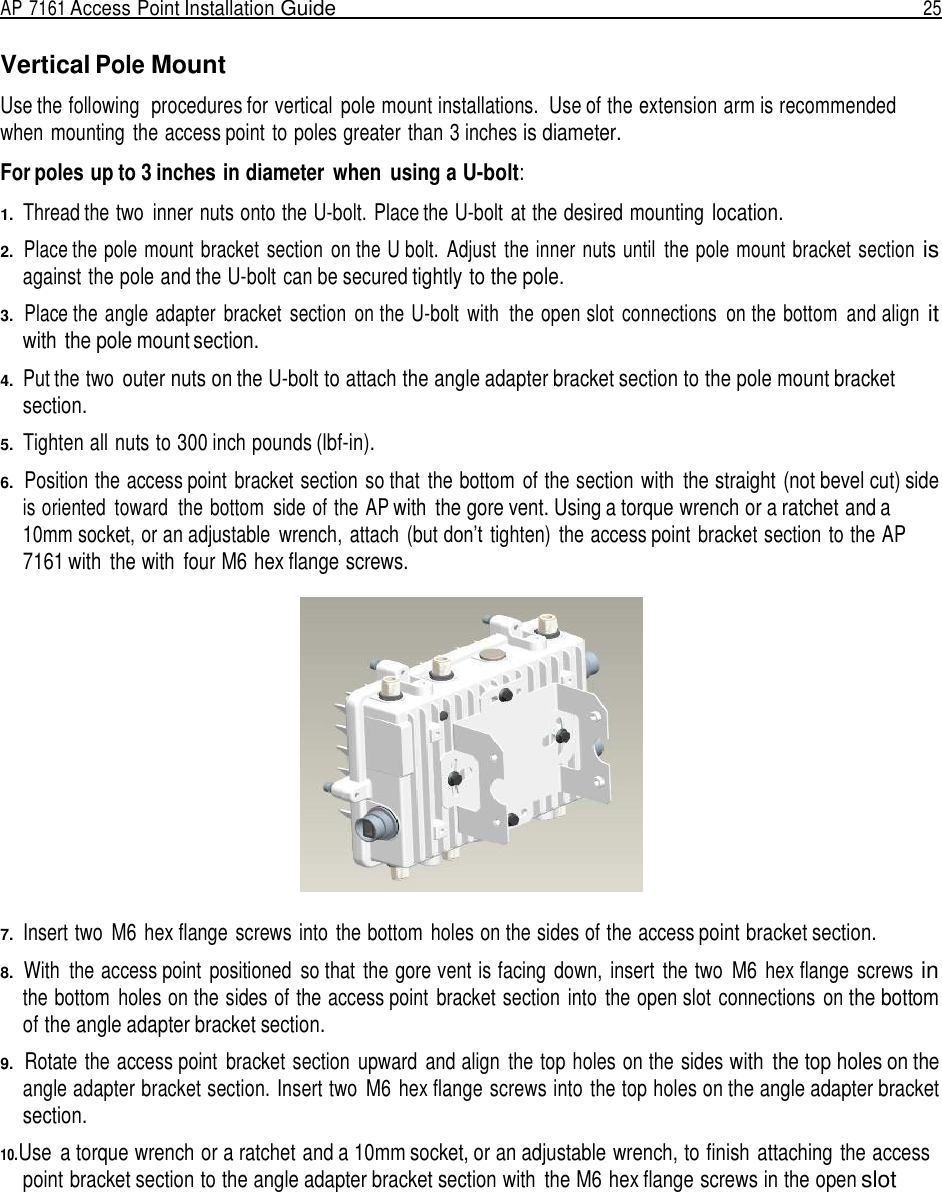
- 1. Installation Guide - AP-7161
- 2. User manual
- 3. User Manual
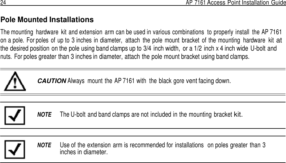
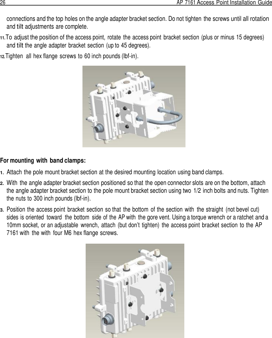
User Manual
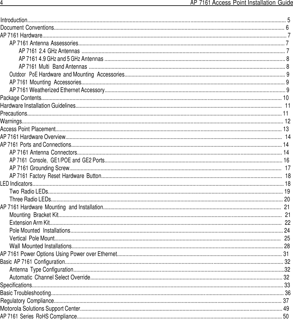
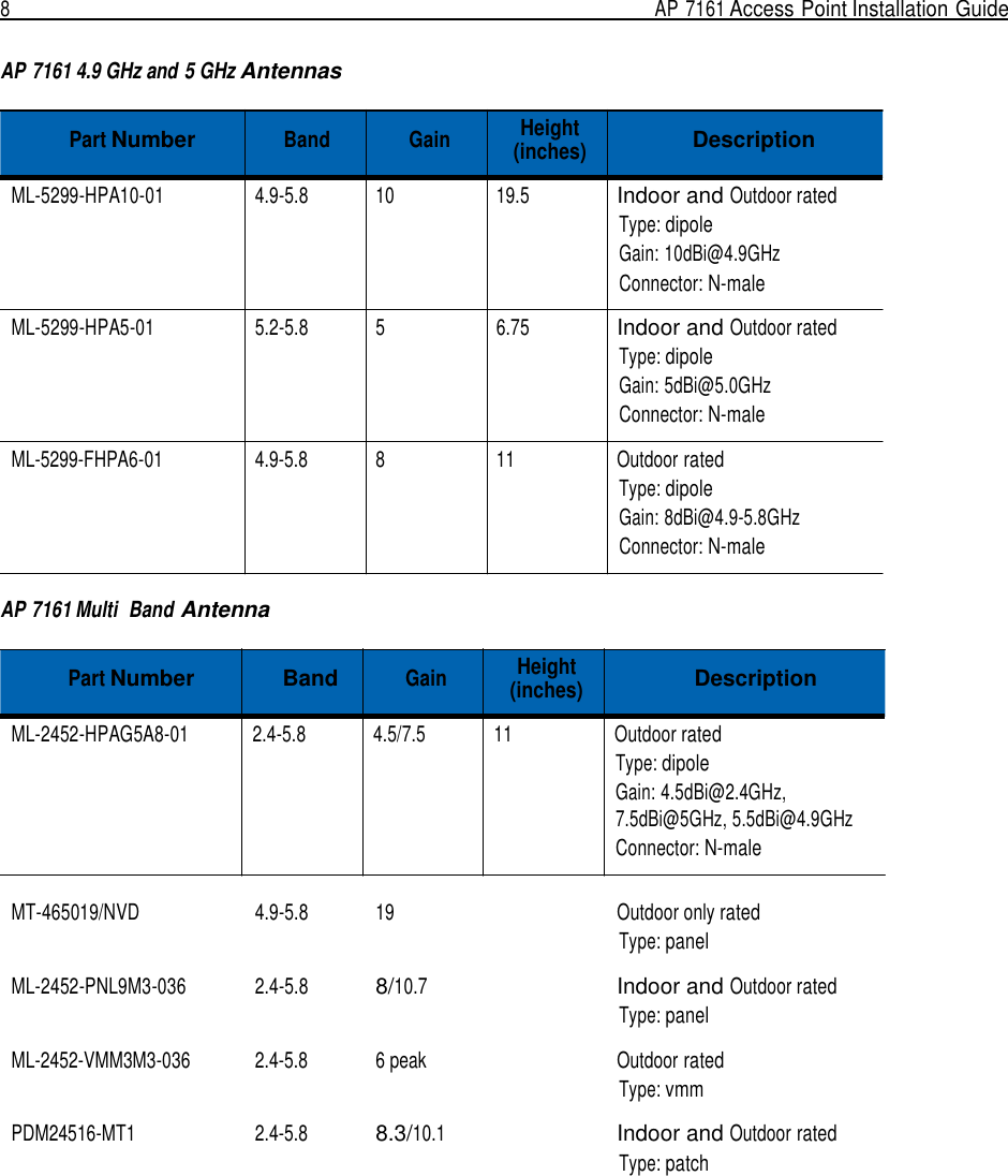
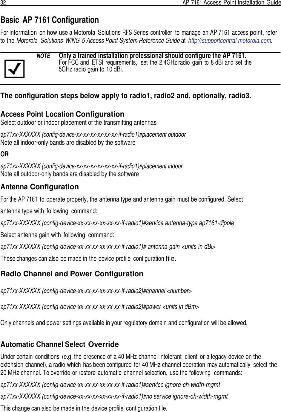
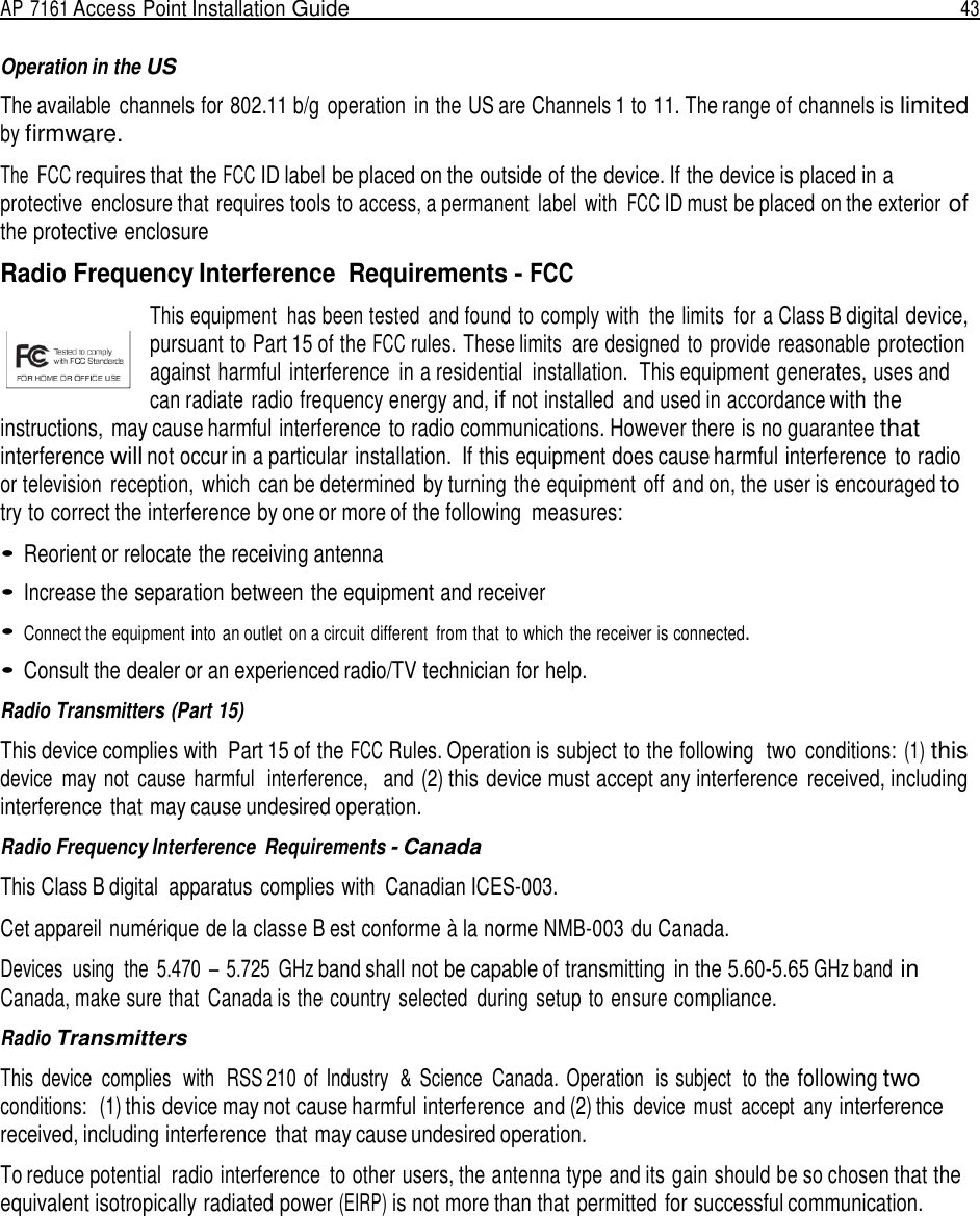
![AP 7161 Access Point Installation Guide 39 We encourage the manufacturers to include information for the users, including the operators and installers, to ensure that they understand that it is incumbent on them to cooperate with manufacturers to implement any changes necessary to facilitate compliance. 5 Devices may be optionally designed not to transmit on channels which overlap 5570 – 5680 MHz instead of requiring installers to perform site-by-site adjustments. In that case it is still required that the devices should be installed professionally and the procedures for registering the device in the industry database should be included in the Users Manual. 6 A voluntary WISPA sponsored database has been developed that allows operators and installers to register the location information of the UNII devices operating outdoors in the 5470 – 5725 MHz band within 35 km of any TDWR location (see http://www.spectrumbridge.com/udia/home.aspx). This database may be used by government agencies in order to expedite resolution of any interference to TDWRs. 7 For example, device software must not have any country code options or software configuration settings which allow an end user to modify the DFS operation or impact the performance of DFS. See KDB 594280. 8 The TCBs are not permitted to approve transmitters with radar detection capabilities. See KDB 628591. 9 The manufacturers may consider taking steps providing clear instructions to operators and installers of devices as to the need to comply with rules for use of the band, guidance on registration of devices and any other processes that are designed to avoid interference. They may use methods that include, but are not limited to, instructions in manuals, notification on product web pages and service bulletins issued for products in the field. TDWR Location Information STATE CITY LONGITUDE LATITUDE FREQUENCY TERRAIN ELEVATION (MSL) [ft] ANTENNA HEIGHT ABOVE TERRAIN [ft] GA ATLANTA W 084 15 44 N 33 38 48 5615 MHz 962 113 IL MCCOOK W 087 51 31 N 41 47 50 5615 MHz 646 97 IL CRESTWOOD W 087 43 47 N 41 39 05 645 MHz 663 113 IN INDIANAPOLIS W 086 26 08 N 39 38 14 5605 MHz 751 97 KS WICHITA W 097 26 48 N 37 30 26 5603 MHz 1270 80 KY COVINGTON W 084 34 48 N 38 53 53 5610 MHz 942 97](https://usermanual.wiki/Zebra-Technologies/AP716102.User-Manual/User-Guide-1840678-Page-39.png)
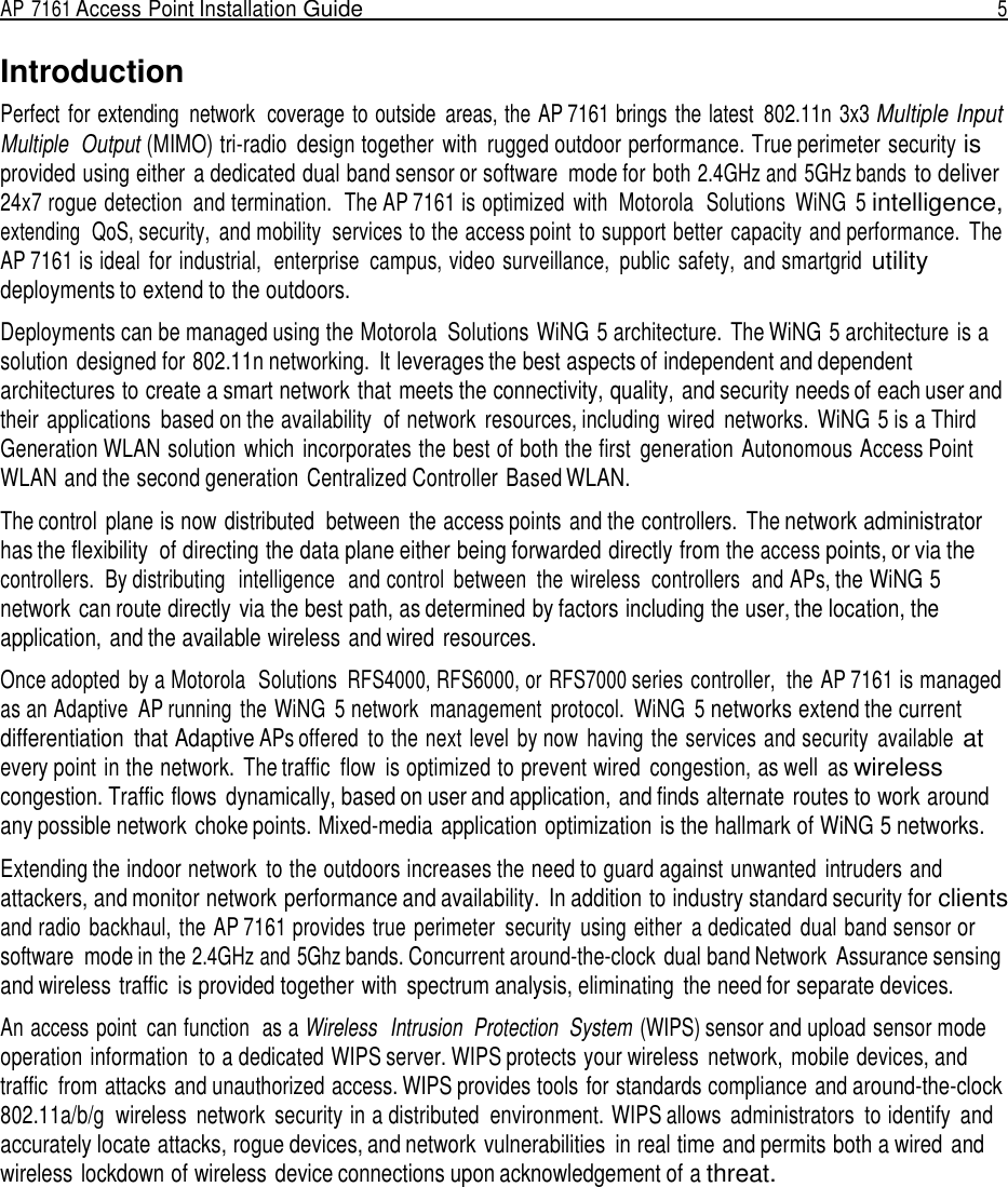
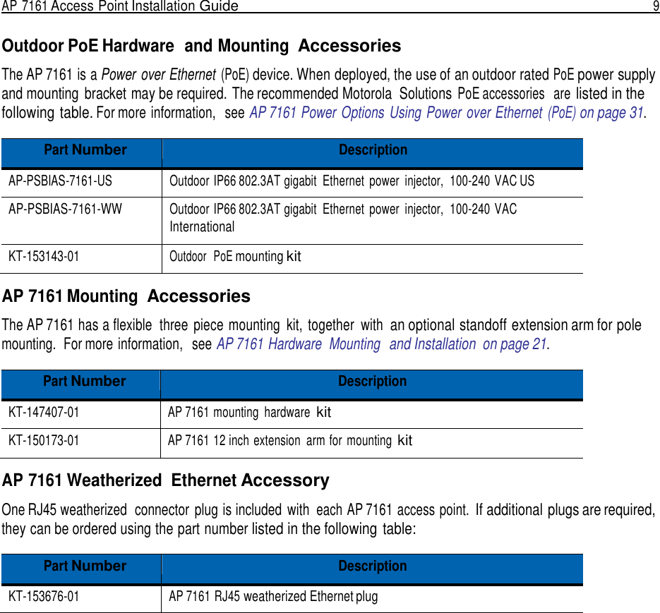
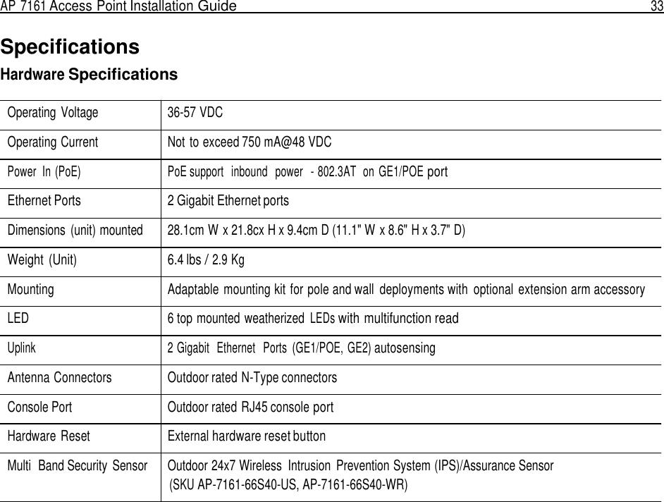
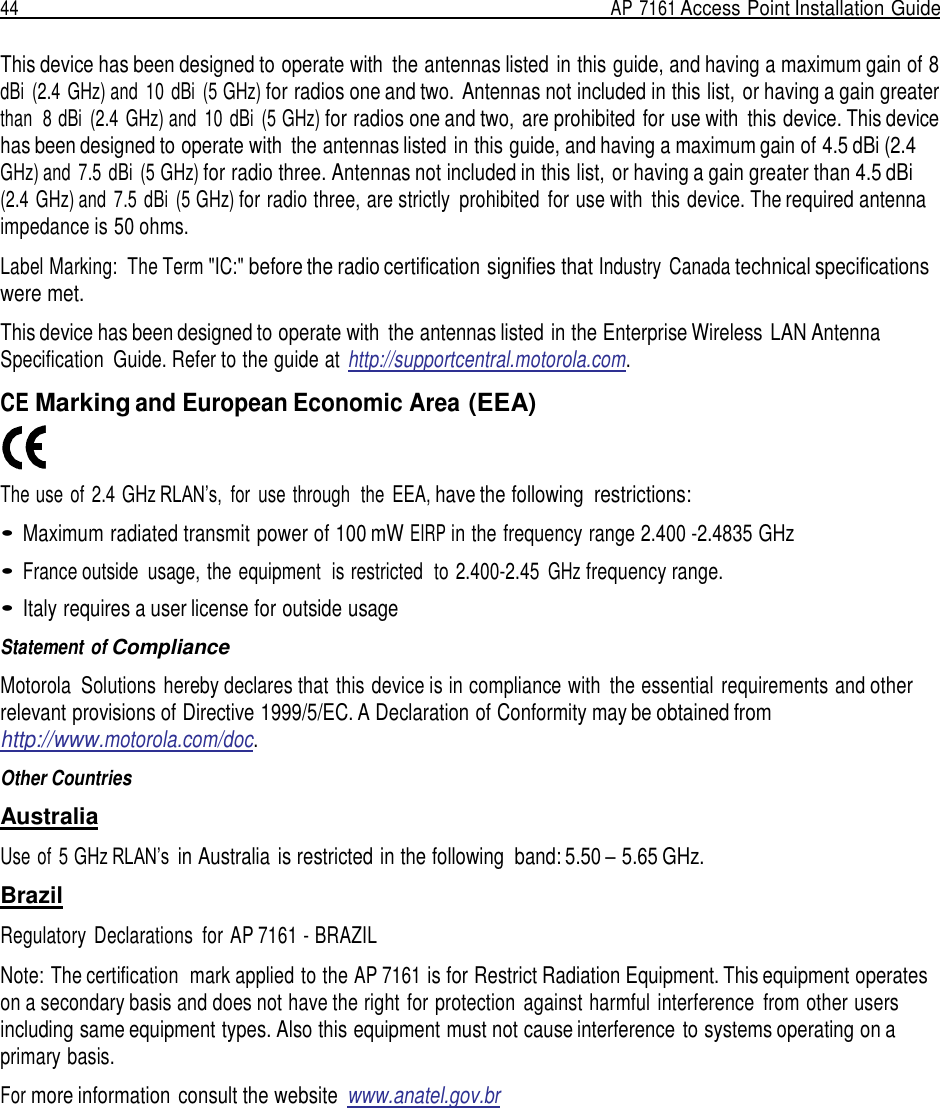
![40 AP 7161 Access Point Installation Guide STATE CITY LONGITUDE LATITUDE FREQUENCY TERRAIN ELEVATION (MSL) [ft] ANTENNA HEIGHT ABOVE TERRAIN [ft] KY LOUISVILLE W 085 36 38 N 38 02 45 5646 MHz 617 113 LA NEW ORLEANS W 090 24 11 N 30 01 18 5645 MHz 2 97 MA BOSTON W 070 56 01 N 42 09 30 5610 MHz 151 113 MD BRANDYWINE W 076 50 42 N 38 41 43 5635 MHz 233 113 MD BENFIELD W 076 37 48 N 39 05 23 5645 MHz 184 113 MD CLINTON W 076 57 43 N 38 45 32 5615 MHz 249 97 MI DETROIT W 083 30 54 N 42 06 40 5615 MHz 656 113 MN MINNEAPOLIS W 092 55 58 N 44 52 17 5610 MHz 1040 80 MO KANSAS CITY W 094 44 31 N 39 29 55 5605 MHz 1040 64 MO SAINT LOUIS W 090 29 21 N 38 48 20 5610 MHz 551 97 MS DESOTO COUNTY W 089 59 33 N 34 53 45 5610 MHz 371 113 NC CHARLOTTE W 080 53 06 N 35 20 14 5608 MHz 757 113 NC RALEIGH DURHAM W 078 41 50 N 36 00 07 5647 MHz 400 113 NJ WOODBRIDGE W 074 16 13 N 40 35 37 5620 MHz 19 113 NJ PENNSAUKEN W 075 04 12 N 39 56 57 5610 MHz 39 113 NV LAS VEGAS W 115 00 26 N 36 08 37 5645 MHz 1995 64 NY FLOYD BENNETT FIELD W 073 52 49 N 40 35 20 5647 MHz 8 97 OH DAYTON W 084 07 23 N 40 01 19 5640 MHz 922 97 OH CLEVELAND W 082 00 28 N 41 17 23 5645 MHz 817 113 OH COLUMBUS W 082 42 55 N 40 00 20 5605 MHz 1037 113 OK AERO. CTR TDWR #1 W 097 37 31 N 35 24 19 5610 MHz 1285 80](https://usermanual.wiki/Zebra-Technologies/AP716102.User-Manual/User-Guide-1840678-Page-40.png)
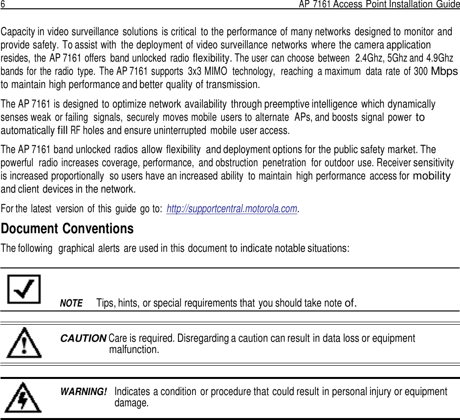
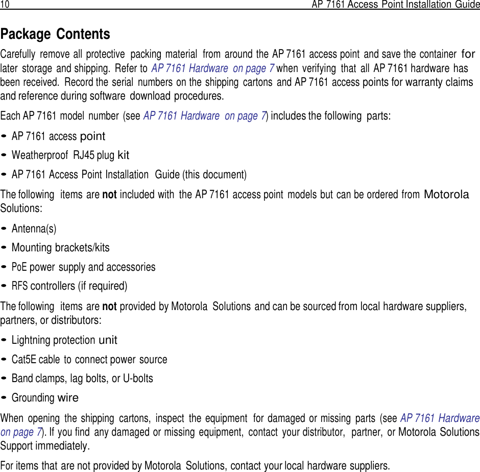
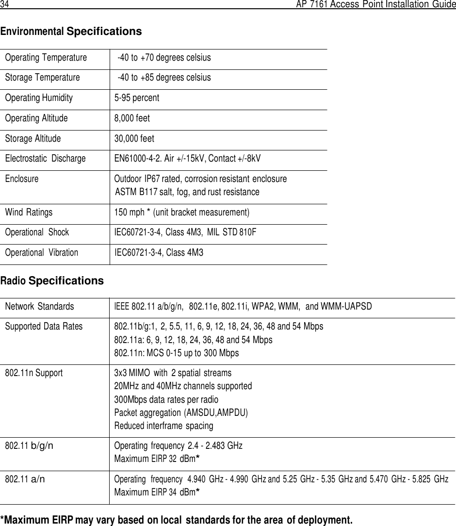
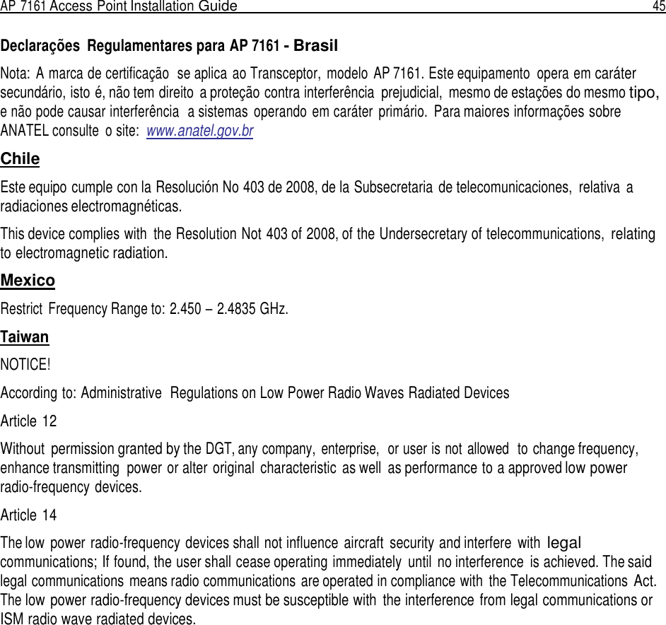
![AP 7161 Access Point Installation Guide 41 STATE CITY LONGITUDE LATITUDE FREQUENCY TERRAIN ELEVATION (MSL) [ft] ANTENNA HEIGHT ABOVE TERRAIN [ft] OK AERO. CTR TDWR #2 W 097 37 43 N 35 23 34 5620 MHz 1293 97 OK TULSA W 095 49 34 N 36 04 14 5605 MHz 712 113 OK OKLAHOMA CITY W 097 30 36 N 35 16 34 5603 MHz 1195 64 PA HANOVER W 080 29 10 N 40 30 05 5615 MHz 1266 113 PR SAN JUAN W 066 10 46 N 18 28 26 5610 MHz 59 113 TN NASHVILLE W 086 39 42 N 35 58 47 5605 MHz 722 97 TX HOUSTON INTERCONTL W 095 34 01 N 30 03 54 5605 MHz 154 97 TX PEARLAND W 095 14 30 N 29 30 59 5645 MHz 36 80 TX DALLAS LOVE FIELD TX LEWISDALE DFW W 096 58 06 N 32 55 33 5608 MHz 541 80 W 096 55 05 N 33 03 53 5640 MHz 554 31 UT SALT LAKE CITY W 111 55 47 N 40 58 02 5610 MHz 4219 80 VA LEESBURG W 077 31 46 N 39 05 02 5605 MHz 361 113 WI MILWAUKEE W 088 02 47 N 42 49 10 5603 MHz 820 97113 Wireless Country Approvals Regulatory markings are applied to the device signifying the radio(s) are approved for use in the following countries: United States, Canada, Australia, and Europe. Please refer to the Declaration of Conformity (DoC) for details of other country markings. This is available at: http://www.motorola.com/doc. Note 1: For 2.4 GHz Products: Europe includes, Austria, Belgium, Bulgaria, Czech Republic, Cyprus, Denmark, Estonia, Finland, France, Germany, Greece, Hungary, Iceland, Ireland, Italy, Latvia, Liechtenstein, Lithuania, Luxembourg, Malta, Netherlands, Norway, Poland, Portugal, Romania, Slovak Republic, Slovenia, Spain, Sweden, Switzerland and the United Kingdom. Operation of the device without regulatory approval is illegal.](https://usermanual.wiki/Zebra-Technologies/AP716102.User-Manual/User-Guide-1840678-Page-41.png)
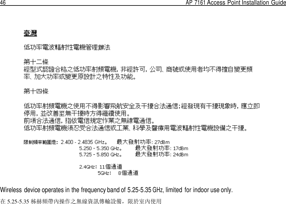
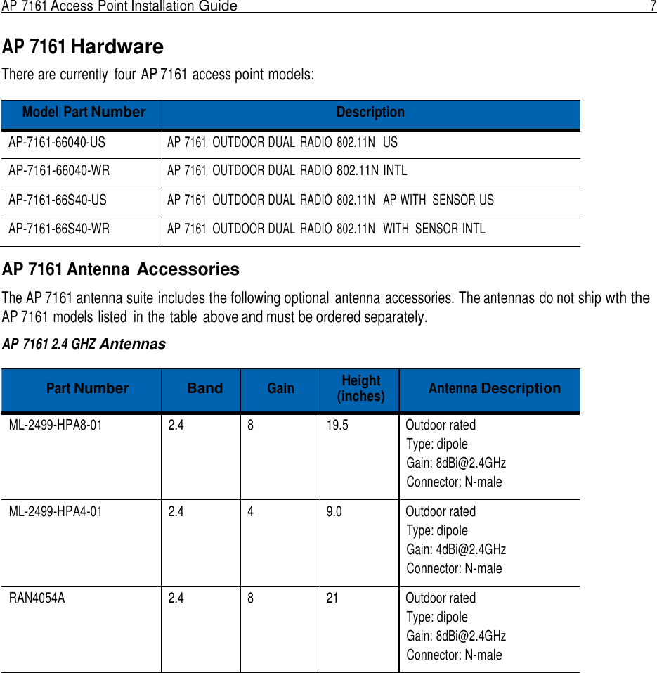
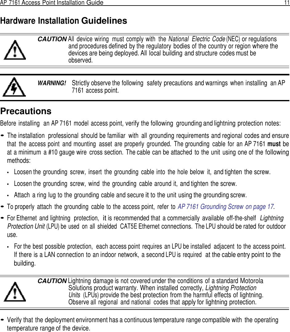
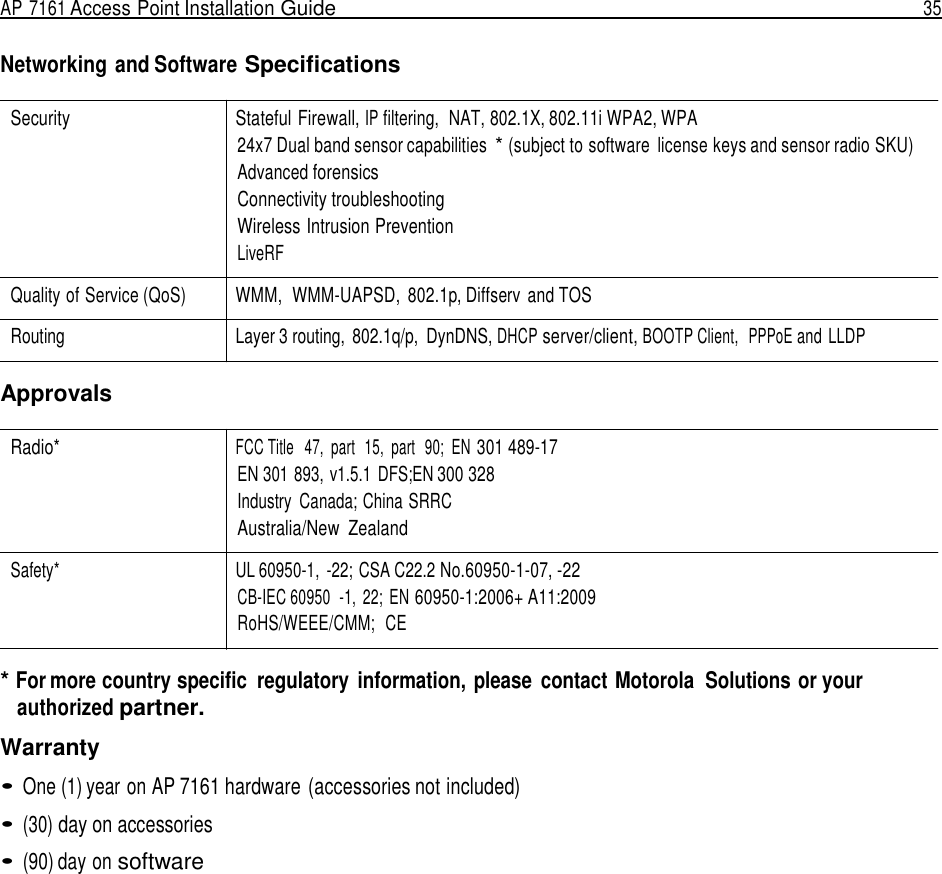
![AP 7161 Ace ess Point I nsta II ation Guide 47 1[ Waste Electrical and Electronic WEEE English: For EU Customers: All products at the end or their tile must be returned to Motorola for recycling. For information on how to return product,please go to: http://www.symbol.com/erwironmental_compliance. Bulgallsh:3a Kll"C>rrH OT EC: CnoA pa• Ha nonc3""" MM >K«OOT BCOIY K" npoAYKT" Tp•6ua Aa ce BPbiJiaT Ha Motorola 3a pe[IHKilMpaHe. 3a l1Hr:j)OpMa[ll1OTHOCHO BPbiJiaHeTO Ha npOAYKTI1, MOnSOT>1AeTe Ha aApec:http://www.symbot.com/weeetink. tei1fna: Pro zakazniky z EU:Vsechny produkty je nutne po skoncenf jejich zivotnosti vralit spotecnosti Motorola k recyktaci. tnformace o zpusobu vraceni produktu najdete na webove strance: http://www.symbot.com/cnvironmcntat_compit anco. Danek: Tit kunder iEU: A tte produkter skat relurnereslit Motorolalit recirkutering, nar de er udtjent. L<es optysningerne om returnering at produkter p\;:hltp:/!www.symbot.com/ environmental_compliance. Deulldl; Fur Kundeninnerhalb der EU: Aile Produkte mussen am Ende i hrer Lebensdauer zum Recycling an Motorola zuri)ckgcsandt worden. Informationen zur Rilcksendung von Produkten inden Sie unter http://www.symbot.com/environmental_compliance. Eeatl: EL klientidclc:koik tooted tulcb ncndc cluca loppcdes tagastada taaskasutamise eesmargil Motorolai'le. Lisainformatsioonisaamiseks toote tagastamise kohta klilastage palun aadressi: hl tp://www.syrnbol.com/environrnental_cornpliance. Espallol: l"ara clientes en Ia Union Europea: todos los productos deben\n entregarse a Motorola at final de su ciclo de vida para que sean reciclados. Si desea mas informacion sobre como dovolvcr un producto,visito:htlp://www.symbol.com/cnvironmcntat_compliance. EM, rK6!rl<l mAurr.<; OTI]V E. E.: 0Aa TU npo'i6VTO, OTO rtAo<; Tl]<; 61irpKtiU<;W <; TOU<;, nptml vo tTTIOTPt<POVTOI OTI]V Motorola VIO OVOKUK Moq. r,a TTtPIOOCIT£Pt<; nl\qpO<POPit<; oxcnKat rqv cmorpo<Ptv6<; npoi'6VTo<;,cmoKt<P9dTt rq o1cuauvol] http://www.symbol.com/environmental_compliance mo C.u:roiKruo. Fl811981s : Clients de !'Union Europeenne : Tous les produi s en fin de cycle de vie doivent etre retournes il Motorola pour recyclage. I"our cle plus ampies informations sur le retour de produits,consultez : http:/r\w..w.symbol.com/environmental_oompliance. Italiano:per i clienti deii'UE: tutli i prodolli che sono giunti at termine del rispettivo ciclo di vita devono essere restituiti a Motorola al fine di consentirne il riciclaggio. Per informazioni sulle modalila di rest!uzione,vlsilare il seguente silo Web: http://www.symbol.com/ environmental_compliance. Latvletu: ES klientiem: visi produktipee to kalposanas miiza beigamir janogiida atpakal Motorola otrreizejaiparstd;idei. Lai iegutu informaciju par produktu nogadiiilanu Motorola, lliclzu, skat et: http://www.symbol.com/environmental_compliance.](https://usermanual.wiki/Zebra-Technologies/AP716102.User-Manual/User-Guide-1840678-Page-47.png)