Zebra Technologies AP716102 Wireless Access Point User Manual AP 7161 Access Point Installation Guide
Zebra Technologies Corporation Wireless Access Point AP 7161 Access Point Installation Guide
Contents
- 1. Installation Guide - AP-7161
- 2. User manual
- 3. User Manual
User Manual
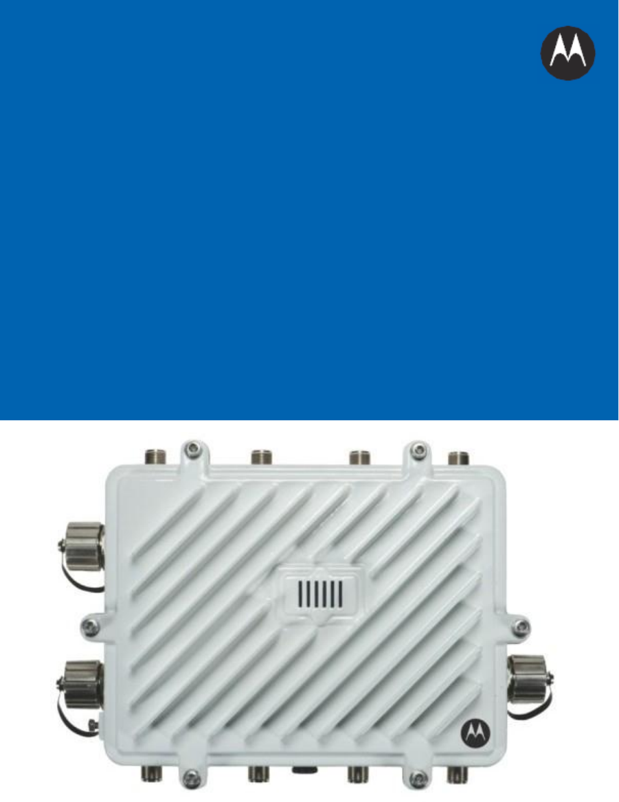
AP 7161
ACCESS
POINT
INSTALLATION GUIDE

2
AP 7161
Access Point Installation Guide

AP 7161
Access Point Installation
Guide
3
Motorola Solutions reserves the right to make changes to any product to improve reliability, function, or design.
Motorola Solutions does not assume any product liability arising out of, or in connection
with, the application or
use of any product, circuit, or application described herein.
No license is granted, either expressly or by implication, estoppel, or otherwise under any patent right
or patent,
covering or relating
to
any combination, system, apparatus, machine, material, method, or process in
which
Motorola Solutions products might be used. An implied license exists only for equipment, circuits, and
subsystems contained
in Motorola Solutions products.
Service
Information
If you have a problem using the equipment, contact your facility’s Technical or Systems Support. If there is a
problem with the equipment, they
will
contact Motorola Solutions Support at:
http://motorolasolutions.com/support.

4
AP 7161
Access Point Installation Guide
Introduction....................................................................................................................................................................................
5
Document Conventions.................................................................................................................................................................. 6
AP
7161
Hardware..........................................................................................................................................................................
7
AP
7161 Antenna Assessories................................................................................................................................................. 7
AP 7161 2.4 GHz
Antennas ............................................................................................................................................... 7
AP
7161
4.9
GHz
and
5
GHz
Antennas
...............................................................................................................................
8
AP 7161
Multi Band
Antennas .......................................................................................................................................... 8
Outdoor PoE
Hardware and Mounting Accessories................................................................................................................. 9
AP 7161
Mounting Accessories............................................................................................................................................... 9
AP
7161
Weatherized
Ethernet
Accessory............................................................................................................................... 9
Package
Contents......................................................................................................................................................................... 10
Hardware
Installation
Guidelines................................................................................................................................................. 11
Precautions...................................................................................................................................................................................
11
Warnings......................................................................................................................................................................................
12
Access Point Placement............................................................................................................................................................... 13
AP
7161
Hardware
Overview........................................................................................................................................................ 14
AP 7161 Ports
and Connections.................................................................................................................................................... 14
AP
7161 Antenna Connectors................................................................................................................................................ 14
AP 7161 Console, GE1/POE and GE2
Ports............................................................................................................................. 16
AP
7161 Grounding Screw..................................................................................................................................................... 17
AP 7161 Factory Reset
Hardware Button............................................................................................................................... 18
LED
Indicators...............................................................................................................................................................................
18
Two Radio LEDs..................................................................................................................................................................... 19
Three Radio LEDs................................................................................................................................................................... 20
AP
7161 Hardware Mounting and Installation............................................................................................................................. 21
Mounting Bracket Kit............................................................................................................................................................. 21
Extension
Arm
Kit................................................................................................................................................................... 22
Pole Mounted
Installations....................................................................................................................................................
24
Vertical Pole Mount............................................................................................................................................................... 25
Wall Mounted
Installations...................................................................................................................................................
28
AP
7161 Power Options Using Power over Ethernet.................................................................................................................... 31
Basic AP 7161
Configuration........................................................................................................................................................
32
Antenna Type
Configuration...................................................................................................................................................32
Automatic Channel Select Override....................................................................................................................................... 32
Specifications...............................................................................................................................................................................
33
Basic Troubleshooting..................................................................................................................................................................
36
Regulatory Compliance................................................................................................................................................................ 37
Motorola
Solutions
Support
Center.............................................................................................................................................. 49
AP 7161 Series RoHS
Compliance................................................................................................................................................ 50

AP 7161
Access Point Installation
Guide
5
Introduction
Perfect for extending network coverage to outside areas, the AP 7161 brings the latest 802.11n 3x3
Multiple Input
Multiple Output (MIMO) tri-radio design together with rugged outdoor performance. True perimeter security
is
provided using either a dedicated dual band sensor or software mode for both
2.4GHz and 5GHz bands
to deliver
24x7 rogue detection and termination. The AP 7161 is optimized with Motorola Solutions WiNG 5
intelligence,
extending QoS,
security, and mobility services to the access point to support better capacity and performance. The
AP 7161 is ideal for industrial, enterprise campus, video surveillance, public safety, and smartgrid
utility
deployments to extend to the outdoors.
Deployments can be managed using the Motorola Solutions WiNG 5 architecture. The WiNG 5 architecture is a
solution designed for 802.11n networking. It
leverages the best aspects of independent and dependent
architectures to create a smart network that meets the connectivity, quality, and security needs of each user and
their applications based on the availability of network resources, including wired networks. WiNG 5 is a Third
Generation WLAN solution which incorporates the best of both the first generation Autonomous Access Point
WLAN and the second generation Centralized Controller Based
WLAN.
The control plane is now distributed between the access points and the controllers. The
network administrator
has the flexibility of directing the data plane either being forwarded directly from the
access
points, or via the
controllers. By distributing intelligence and control between the wireless controllers and APs,
the WiNG 5
network can route directly via the best path, as determined by factors including the user,
the location, the
application, and the available wireless and wired resources.
Once adopted by a Motorola Solutions
RFS4000, RFS6000, or RFS7000
series controller, the AP 7161 is
managed
as an Adaptive AP running the WiNG 5 network management protocol. WiNG 5
networks extend the current
differentiation that Adaptive
APs offered to the next level by now having the services and security available
at
every point in the network. The traffic flow is optimized to prevent wired congestion, as well as
wireless
congestion. Traffic flows dynamically, based on user and application, and finds alternate routes to work around
any possible network choke points. Mixed-media application optimization is the hallmark of WiNG 5
networks.
Extending the indoor network to the outdoors increases the need to guard against unwanted intruders and
attackers, and monitor network performance and availability. In addition to industry standard security for
clients
and radio backhaul, the AP 7161 provides true perimeter security using either a dedicated dual band sensor
or
software mode in the
2.4GHz and 5Ghz
bands. Concurrent around-the-clock dual band Network Assurance sensing
and wireless traffic is provided together with spectrum analysis, eliminating the need for separate devices.
An access point can function as a Wireless Intrusion Protection System (WIPS)
sensor and upload sensor mode
operation information to a dedicated WIPS server. WIPS protects your wireless network, mobile devices, and
traffic from attacks and unauthorized access. WIPS provides tools for standards compliance and
around-the-clock
802.11a/b/g wireless network security in a distributed environment. WIPS allows administrators to identify and
accurately locate attacks, rogue devices, and network vulnerabilities in real time and permits both a wired and
wireless lockdown of wireless device connections upon acknowledgement of a
threat.
6
AP 7161
Access Point Installation Guide
Capacity in video surveillance solutions is critical to the performance of many networks designed to monitor and
provide safety. To assist with the deployment of video surveillance networks where the camera
application
resides, the AP 7161 offers band unlocked radio
flexibility.
The user can choose between 2.4Ghz, 5Ghz and 4.9Ghz
bands for the radio type. The AP 7161 supports 3x3 MIMO technology, reaching a maximum data rate of 300
Mbps
to maintain high performance and better quality of transmission.
The AP 7161 is designed
to optimize network availability through preemptive intelligence which dynamically
senses weak or failing signals, securely moves mobile users to alternate APs, and boosts signal power
to
automatically
fill
RF
holes and ensure uninterrupted mobile user access.
The AP 7161 band unlocked radios
allow flexibility and deployment options for the public safety market. The
powerful radio increases coverage, performance, and obstruction penetration for outdoor use. Receiver
sensitivity
is increased proportionally so users have an increased ability to maintain high performance access for
mobility
and client devices
in the network.
For the latest version of this guide go to: http://supportcentral.motorola.com
.
Document Conventions
The following graphical alerts are used in this document
to indicate notable situations:
NOTE
Tips, hints, or special requirements that you should take note
of.
CAUTION
Care
is required. Disregarding a caution can result in data loss or equipment
malfunction.
WARNING!
Indicates a condition or procedure
that could result in personal injury or equipment
damage.

AP 7161
Access Point Installation
Guide
7
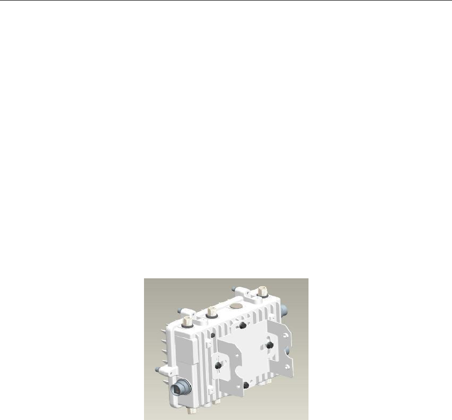
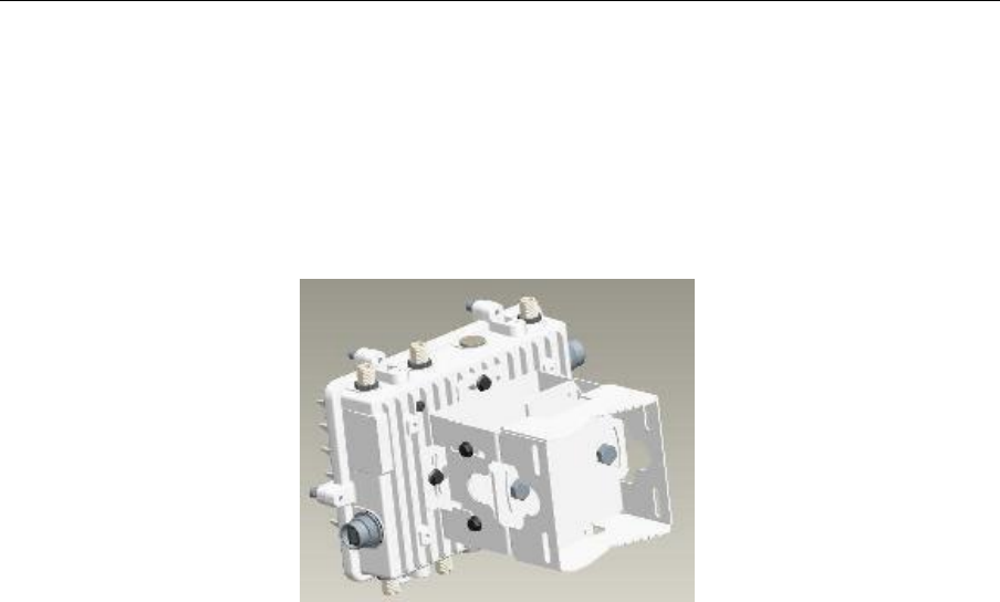
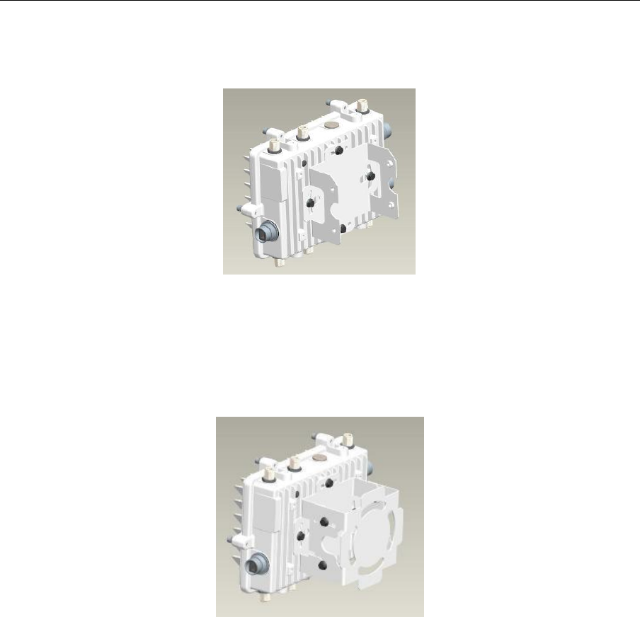
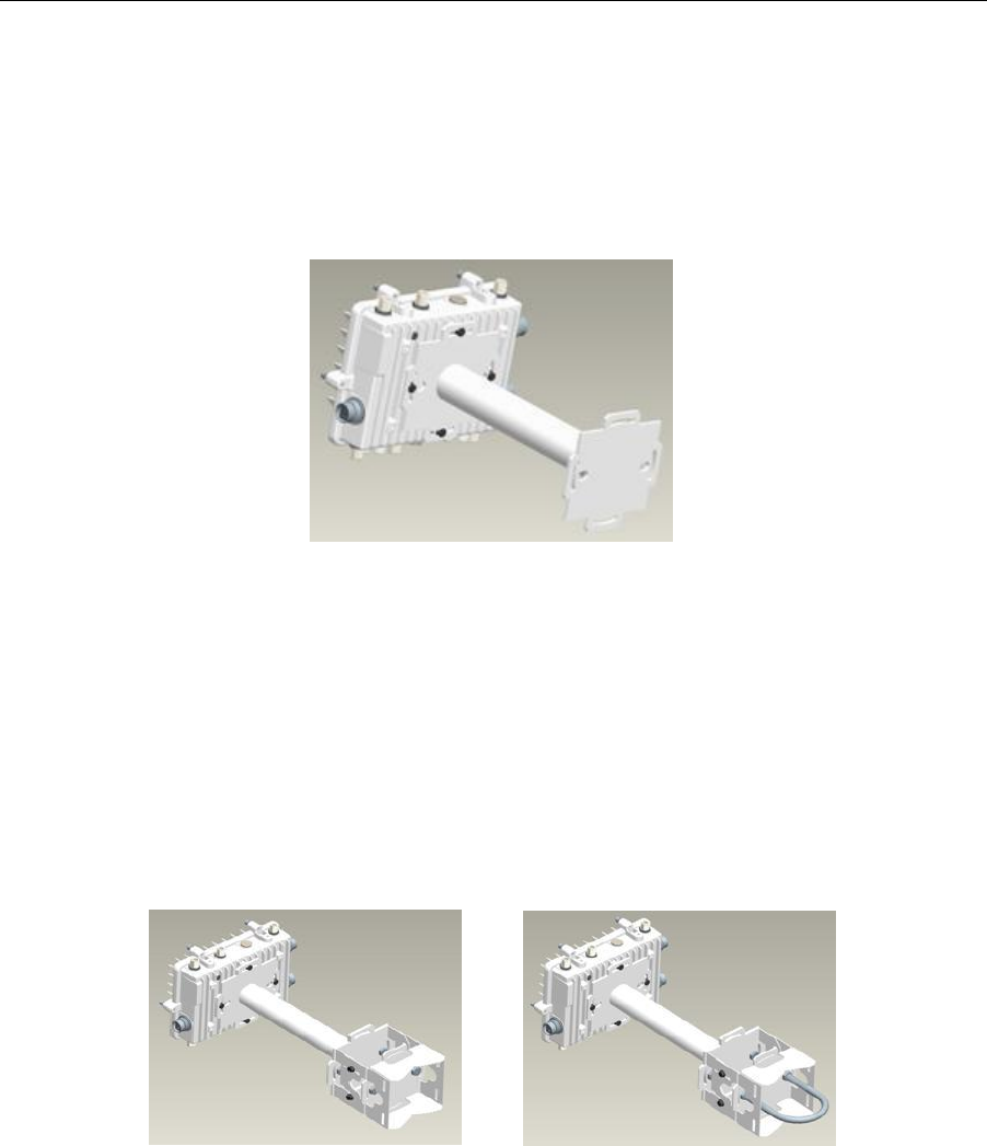
AP 7161
Hardware
There are currently four AP 7161 access
point models:
Model Part
Number
Description
AP-7161-66040-US
AP 7161 OUTDOOR DUAL RADIO 802.11N
US
AP-7161-66040-WR
AP 7161 OUTDOOR DUAL RADIO
802.11N INTL
AP-7161-66S40-US
AP 7161 OUTDOOR DUAL RADIO 802.11N AP WITH SENSOR
US
AP-7161-66S40-WR
AP 7161 OUTDOOR DUAL RADIO 802.11N WITH SENSOR
INTL
AP 7161 Antenna
Accessories
The AP
7161 antenna suite includes the following optional
antenna accessories. The antennas do not ship
wth the
AP 7161 models listed in the table
above and must be ordered separately.
AP 7161 2.4 GHZ
Antennas
Part
Number Band
Gain
Height
(inches)
Antenna
Description
ML-2499-HPA8-01
2.4
8
19.5
Outdoor
rated
Type:
dipole
Gain: 8dBi@2.4GHz
Connector:
N-male
ML-2499-HPA4-01
2.4
4
9.0
Outdoor
rated
Type:
dipole
Gain: 4dBi@2.4GHz
Connector:
N-male
RAN4054A
2.4
8
21
Outdoor
rated
Type:
dipole
Gain: 8dBi@2.4GHz
Connector:
N-male

8
AP 7161
Access Point Installation Guide
AP 7161 4.9 GHz and 5 GHz
Antennas
Part
Number
Band
Gain
Height
(inches)
Description
ML-5299-HPA10-01
4.9-5.8
10
19.5
Indoor and
Outdoor
rated
Type:
dipole
Gain: 10dBi@4.9GHz
Connector:
N-male
ML-5299-HPA5-01
5.2-5.8
5
6.75
Indoor and
Outdoor
rated
Type:
dipole
Gain: 5dBi@5.0GHz
Connector:
N-male
ML-5299-FHPA6-01
4.9-5.8
8
11
Outdoor
rated
Type:
dipole
Gain: 8dBi@4.9-5.8GHz
Connector:
N-male
AP 7161 Multi Band
Antenna
Part
Number Band
Gain
Height
(inches)
Description
ML-2452-HPAG5A8-01
2.4-5.8
4.5/7.5
11
Outdoor
rated
Type:
dipole
Gain: 4.5dBi@2.4GHz,
7.5dBi@5GHz, 5.5dBi@4.9GHz
Connector:
N-male
MT-465019/NVD
4.9-5.8
19
Outdoor only
rated
Type:
panel
ML-2452-PNL9M3-036
2.4-5.8
8/
10.7
Indoor and
Outdoor
rated
Type:
panel
ML-2452-VMM3M3-036
2.4-5.8
6 peak
Outdoor
rated
Type:
vmm
PDM24516-MT1
2.4-5.8
8.3/
10.1
Indoor and
Outdoor
rated
Type:
patch

AP 7161
Access Point Installation
Guide
9
Outdoor PoE Hardware and Mounting
Accessories
The AP 7161 is a Power over Ethernet
(PoE)
device. When deployed, the use of an outdoor rated
PoE
power supply
and mounting bracket may be required. The recommended Motorola Solutions
PoE accessories are
listed in the
following table.
For more information, see AP 7161 Power Options Using Power over Ethernet
(PoE)
on page 31.
Part
Number
Description
AP-PSBIAS-7161-US
Outdoor IP66 802.3AT gigabit Ethernet power injector, 100-240 VAC U
S
AP-PSBIAS-7161-WW
Outdoor IP66 802.3AT gigabit Ethernet power injector, 100-240 VAC
International
KT-153143-01
Outdoor PoE
mounting
kit
AP 7161 Mounting
Accessories
The AP 7161 has a flexible three piece mounting kit, together with
an optional standoff extension arm for pole
mounting. For more information, see AP 7161 Hardware Mounting
and Installation on page 21.
Part
Number
Description
KT-147407-01
AP 7161 mounting hardware
kit
KT-150173-01
AP 7161 12 inch extension arm for mounting
kit
AP 7161
Weatherized Ethernet
Accessory
One RJ45 weatherized connector plug is included with
each AP 7161 access point.
If additional plugs are required,
they can be ordered using the part number
listed in the following table:
Part
Number
Description
KT-153676-01
AP 7161 RJ45
weatherized Ethernet plug

10
AP 7161
Access Point Installation Guide
Package Contents
Carefully remove all protective packing material from around the AP 7161 access point and save the container
for
later storage and shipping. Refer to AP 7161 Hardware on page 7 when verifying that all AP
7161 hardware has
been received. Record the serial numbers on the shipping cartons and AP 7161 access
points for warranty claims
and reference during software download procedures.
Each AP 7161 model number (see AP 7161 Hardware on page 7)
includes the following parts:
•
AP 7161 access
point
•
Weatherproof RJ45 plug
kit
•
AP 7161 Access Point Installation
Guide (this document)
The following items are
not
included with the
AP 7161 access point models but can be ordered from
Motorola
Solutions:
•
Antenna(s)
•
Mounting brackets/kits
•
PoE
power supply and accessories
•
RFS
controllers (if required)
The following items are
not
provided by Motorola Solutions and can be sourced
from local hardware suppliers,
partners, or
distributors:
•
Lightning protection
unit
•
Cat5E cable to
connect power source
•
Band clamps,
lag bolts, or U-bolts
•
Grounding
wire
When opening the shipping cartons, inspect the equipment for damaged or missing parts (see AP 7161
Hardware
on page 7). If you find any damaged or missing equipment, contact your distributor, partner, or
Motorola Solutions
Support
immediately.
For
items that are not provided by Motorola Solutions, contact your local hardware suppliers.
AP 7161
Access Point Installation
Guide
11
Hardware Installation
Guidelines
CAUTION
All device wiring must comply with the National Electric Code
(NEC)
or regulations
and procedures defined by the regulatory bodies of the country or region
where the
devices are being deployed. All local building and structure codes must
be
observed.
WARNING!
Strictly
observe the following safety precautions and warnings when installing an AP
7161 access
point.
Precautions
Before installing an AP 7161 model access
point, verify the following grounding and lightning protection notes:
•
The
installation professional should be familiar with all grounding requirements and regional codes and ensure
that the access point and mounting asset are properly grounded. The grounding cable for an AP
7161
must
be
at a minimum a #10 gauge wire cross section. The cable can be attached to the unit using one of the
following
methods:
•
Loosen the grounding screw, insert the grounding cable into the hole below it,
and tighten the screw.
•
Loosen the grounding screw, wind the grounding cable around it,
and tighten the screw.
•
Attach a ring lug to the grounding cable and secure
it
to the unit using the grounding screw.
•
To properly attach the grounding cable to the access point, refer to AP
7161 Grounding Screw on page 17.
•
For Ethernet and lightning protection,
it
is recommended that a commercially available off-the-shelf
Lightning
Protection Unit
(LPU) be used on
all shielded CAT5E
Ethernet connections. The
LPU
should be rated for outdoor
use.
•
For
the best possible protection, each access point requires an
LPU
be installed adjacent to the access
point.
If there is a LAN connection to an indoor network, a second
LPU is required
at the cable entry point to the
building.
CAUTION
Lightning damage is not covered under the conditions of a standard
Motorola
Solutions product warranty. When installed correctly, Lightning Protection
Units (LPUs)
provide the best protection from the harmful effects of
lightning.
Observe all regional and national codes
that apply for lightning protection.
•
Verify that the deployment environment has a continuous temperature range compatible with the operating
temperature range of the device.

12
AP 7161
Access Point Installation Guide
Warnings
•
Read all installation instructions and site survey reports, and
verify correct equipment installation before
connecting the access point to its power source.
•
Remove
jewelry and watches before installing this equipment.
•
Verify that the unit is grounded before connecting
it
to the power source.
•
Verify that any device connected to this unit is properly wired and grounded.
•
Connect all power cords to a properly wired and grounded electrical circuit. Verify
that the electrical circuits
have appropriate overload
protection.
•
Attach only approved power cords to the device.
•
Verify that the power connector and socket are accessible at all times during the operation of the equipment.
•
Do not hold any component containing a radio such that
it
is very close to or touching any exposed parts
of the
body, especially the face or eyes, while
transmitting.
•
Do not work with power circuits in dimly
lit
spaces.
•
Do not install this equipment or work with its power circuits during thunderstorms or other weather conditions
that could cause a power surge.
•
Verify there is adequate ventilation around the device, and that ambient temperatures meet equipment
operation specifications.
•
Avoid contact with overhead
power lines.
•
Take precautions to avoid injury from falling tools and equipment. Crews should wear hard hats in and around
the installation work
site.
•
Be aware of vehicular traffic in and around the installation work
site.
•
Do not operate a portable transmitter near unshielded blasting caps or in an environment where explosives are
present unless the transmitter is especially certified for such use.
•
Refer to your site survey and network analysis reports to determine specific requirements for each
deployment.
•
Assign installation responsibility to the appropriate personnel.
•
Identify and document where all installed components are located.
•
Identify and prepare Ethernet and console port connections.
•
Verify that cable lengths are within the maximum allowable distances for optimal signal transmission.
CAUTION
The maximum length allowed for
PoE
cables is 100 meters.

AP 7161
Access Point Installation
Guide
13
Access Point
Placement
Observe
the following recommended guidelines to help ensure a successful
network deployment:
•
Identify all pieces of the mounting bracket and mounting extension arm hardware and ancillary hardware (see
AP 7161 Hardware on page
7
).
•
Mount the device with the black gore
vent down.
•
Mounting height for network devices should not exceed 30 to 35 feet. Mounting height should vary
to
accommodate the topography of the deployment area, foliage,
and other obstructions.
•
When mounting an access point, keep the antennas away from any
metal obstructions. Utilize the extension
arm (KT-150173-01)
if
neccesary.
•
Line of Sight (LoS)
guidelines should be given special consideration whenever devices will not be installed in a
straight line, such as deploying devices on alternating sides of
a roadway.
14
AP 7161
Access Point Installation Guide
AP 7161 Hardware
Overview
AP 7161 models can be purchased in a two or three radio configuration (see AP 7161 Hardware on page 7). Each
model has two band unlocked radios that can operate across the 2.4GHz, 4.9GHz, and 5GHz bands, subject
to
country regulatory approval and outdoor/band use.
An AP 7161 must be installed by trained professionals familiar with
RF
planning and regulatory limits defined by
the regulatory bodies of the country where the devices are being deployed. All common precautions for
grounding
and Electrostatic Discharge
(ESD)
protection should be observed during deployment and installation.
AP
7161
access points must be installed such that no harmful interference results from device
operation.
AP 7161
Ports and Connections
The AP 7161 access
point has the following port designations:
•
Antenna ports R1-A, B and C, R2-A, B and C, and R3-A and B
•
Console
port
•
GE1/POE - LAN
port
•
GE2
- WAN port
The following sections describe the ports and connections for the
AP
7161.
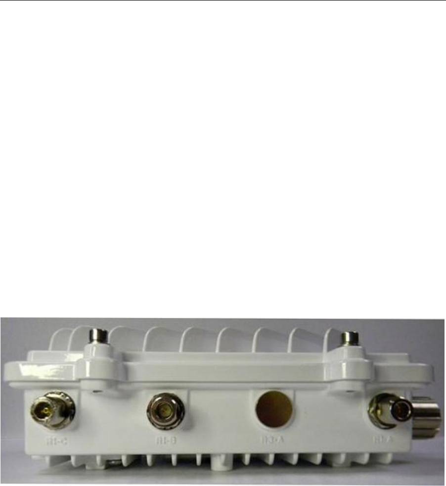
AP 7161 Antenna
Connectors
AP 7161
two radio models (AP-7161-66040-US and AP-7161-66040-WR) are configured with
six N type connectors
to support two active WLAN data radios.
When mounting antennas to ports R1-A, R1-B, and R1-C, ensure that you have selected the appropriate band
for
the configured radio that uses ports R1-A, R1-B, and R1-C. In this instance, R1 ports relate to the
software
configured radio 1 settings.
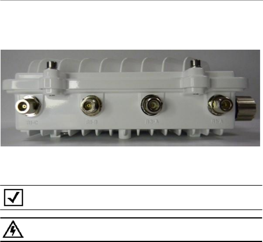
AP 7161
Access Point Installation
Guide
15
When mounting antennas to connectors marked R2-A, R2-B and R2-C, these antenna ports relate to
the software
settings of radio 2. Care must be taken to provide the correct antenna for the operating band of each
port.
AP 7161 three radio models (AP-7161-66S40-US and AP-7161-66S40-WR) are configured
with eight N type
connectors to support two active WLAN data radios and a dedicated sensor radio as the
third.
As with two radio models, the rules for ports R1-A, R1-B and R1-C and R2-A, R2-B and R2-C
apply. R3-A and R3-B
are the ports reserved for the sensor radio, and an appropriate multi band antenna should be mounted to the
unit
for sensor
operation.
NOTE
The sensor radio does not function
as a WLAN data radio.
WARNING!
Antenna ports where no antenna is mounted must be properly terminated using an
approved IP67
terminator.
16
AP 7161
Access Point Installation Guide
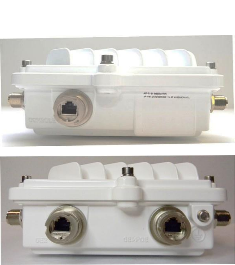
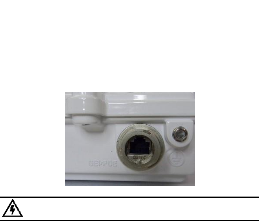
AP 7161 Console, GE1/POE and GE2
Ports
The AP 7161 has Ethernet ports for external console, GE1/POE, and GE2
connections.To gain access
to the ports
you
will
need to remove the protective caps.
The Ethernet cable from the PoE device (if used) connects to the GE1/POE port on the
unit.
AP 7161
Access Point Installation
Guide
17
The GE2 port on the unit can be used
if
a second data connection for an external device (e.g. surveillance camera)
is required. Ensure the GE2
WAN port has been configured to permit an attached external device during
the
configuration process.
When making connections using these ports, a properly rated RJ45 connector is required. One
weatherproof RJ45
plug kit is provided with each access point. When connecting cables to the AP 7161 Ethernet ports,
follow the
instructions in the connector packaging and tighten the connectors to create a weatherproof seal. Shielded cables
are required.
AP 7161 Grounding
Screw
The grounding screw is located to the right of the GE1/POE port and above the GND
symbol.
WARNING!
The grounding cable for an AP 7161
must
be at a minimum a #10 gauge wire
cross
section.
The grounding cable can be attached to the unit using one of three recommended methods. Using an 8mm socket
and driver:
•
Loosen the grounding screw and insert the grounding cable into the hole below it. Tighten the grounding
screw
to 30 inch pounds
(lbf-in).
•
Loosen the grounding screw and wind the grounding cable around the screw. Tighten the grounding screw to
30
inch pounds
(lbf-in).
•
Attach a ring lug to the grounding cable and remove the grounding screw to attach the ring lug to the access
point. Secure
it
to the unit by reinserting the grounding screw. Tighten the grounding screw to 30 inch pounds
(lbf-in).
18
AP 7161
Access Point Installation Guide
AP 7161 Factory Reset Hardware
Button
An AP 7161 can be physically reset using the factory reset hardware button. The
button is located inside the reset
port on the bottom of the
unit.
NOTE
This option is not supported by all AP 7161 software releases. Refer
to the release
notes for the appropriate
software.
The reset button is only enabled for a ten second interval as the unit boots up. It can be accessed by removing
the
cover screw using a ratchet driver and a #2 Phillips head adapter. Push the button to reset the access
point.
Confirm that the reset cycle was completed and replace the cover screw.
To perform an external hardware reset and restore the access
point default settings:
1.
Using a #2 phillips screwdriver, remove the cover
screw from the external reset port.
2.
Gently press and
hold the reset button.
3.
If any of LEDs 2 through 6 are active,
it
indicates that the unit has booted successfully and
the operational
software is running.
LED
Indicators
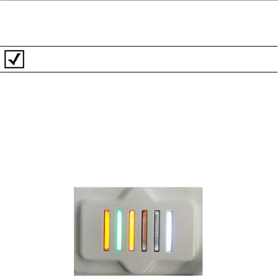
The AP 7161 access point has six LEDs on the top of the access
point housing.
The access point utilizes two different colored lights below each
LED. Only one light displays
within
an LED
at any
given time. Every light within
each LED is exercised during startup to allow the user to see
if
an LED
is not
functioning.
The LEDs
turn on and off while rotating in a circular pattern. Since two
LEDs feed each light pipe,
the
pattern is from left to right (LEDs 1 through 6), then right to left (LEDs
6 through 1).
AP 7161
Access Point Installation
Guide
19
The top housing LEDs
have the following display patterns and
functionality:
Two
Radio
LEDs
A two radio model access point (P/N AP-7161-66040-US and AP-7161-66040-WR) has the
following unique LED
behavior:
LED 1
(Sensor)
LED 2
(2.4 GHz)
LED 3
(5 GHz)
LED 4
(GE2/WAN)
LED 5
(GE1/LAN)
LED 6
(System)
Not Used
Blinking
Emerald
indicates
802.11b/g/n
activity.
Solid
Emerald
indicates a radio
is present but
not
configured.
Blinking
Amber
indicates
802.11a/n
activity.
Solid
Amber
indicates a radio
is present but
not
configured.
LED
Off
indicates the
port is not
connected.
Blinking
Green
indicates
normal
operation.
Rapidly
blinking
Yellow
indicates a port
error.
LED
Off
indicates the
port is not
connected.
Blinking
Green
indicates
normal
operation.
Rapidly
blinking
Yellow
indicates a port
error.
Solid
Red
indicates
diagnostic mode.
Blinking
Red
at 1
second
interval
indicates POST
failure.
Solid
White
following
diagnostic
mode
indicates
booting.
Blinking
Red
and
White
at 1
second
interval
indicates
“no
adoption”.
Solid
White
indicates normal
operation.
WARNING!
If
LED
6 remains blinking
Red
for longer than 10 minutes, cycle the power to
the
unit. If the condition persists, contact the Motorola Solutions support center.

20
AP 7161
Access Point Installation Guide
Three Radio
LEDs
A three radio model access point with sensor (P/N AP-7161-66S40-US and AP-7161-66S40-WR) has the
following
unique LED
behavior:
LED 1
(Sensor)
Blinking
Emerald
and
Amber
at 2
second
interval
indicates a radio
is present but
not connected
to
a server.
Solid
Amber
indicates a radio
is present and
connected to a
server.
LED 2
(2.4 GHz)
Blinking
Emerald
indicates
802.11b/g/n
activity.
Solid
Emerald
indicates a radio
is present but
not
configured.
LED 3
(5
GHz)
Blinking
Amber
indicates
802.11a/n
activity.
Solid
Amber
indicates a radio
is present but
not
configured.
LED 4
(GE2/WAN)
LED
Off
indicates the
port is not
connected.
Blinking
Green
indicates
normal
operation.
Rapidly
blinking
Yellow
indicates a port
error.
LED 5
(GE1/LAN)
LED
Off
indicates the
port is not
connected.
Blinking
Green
indicates
normal
operation.
Rapidly
blinking
Yellow
indicates a port
error.
LED 6
(System)
Solid
Red
indicates
diagnostic mode.
Blinking
Red
at
1
second
interval
indicates POST
failure.
Solid
White
following
diagnostic
mode
indicates
booting.
Blinking
Red
and
White
at 1
second
interval
indicates
“no
adoption”.
Solid
White
indicates normal
operation.
AP 7161
Access Point Installation
Guide
21
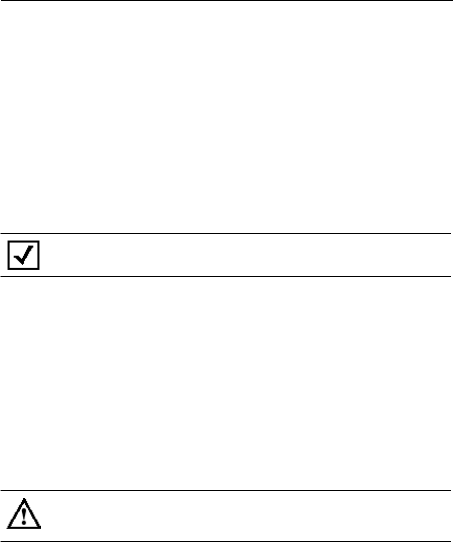
AP 7161 Hardware Mounting and
Installation
It is recommended to use the AP 7161 mounting bracket kit (KT-147407-01)
for most deployments. When a
standoff distance is required for a pole mounted or wall mounted installation, use the extension arm
kit
(KT-150173-01).
The following
sections detail the installation procedure for deploying an AP 7161 access
point:
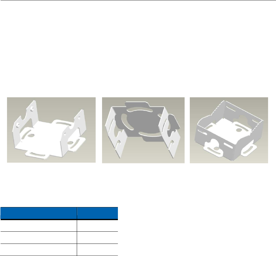
Mounting Bracket
Kit
The AP 7161 mounting bracket kit (KT-147407-01) includes the
Access Point Bracket (left), Angle Adapter Bracket
(center), and Pole
Mount Bracket (right) sections:
The Access Point Bracket and the Angle Adapter Bracket can be adjusted to rotate (plus or minus 15 degrees) and
tilt
(up to 45 degrees) during
installation to orient the unit for optimal positioning.
The following ancillary hardware to assemble the mounting bracket sections is included in the
kit:
Description
Quantity
M6 serrated hex
flanged screws
8
1/2 inch hex head
nut
2
1/2 inch x 3/4 inch hex head
bolt
2
22
AP 7161
Access Point Installation Guide
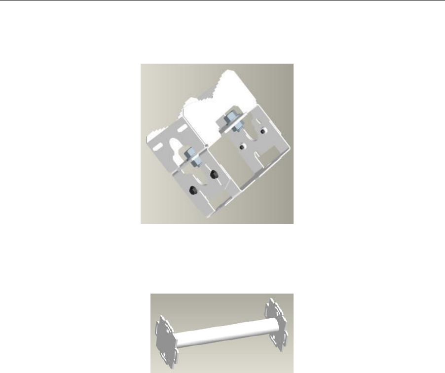
A torque wrench or ratchet with a 10mm adapter, or an adjustable wrench can be used to assemble
the mounting
brackets. A finished assembly of the mounting bracket kit is shown below. Assembly during deployment may
differ to
achieve the required angle and
rotation for optimal positioning.
Extension Arm
Kit
When mounting an AP 7161 on poles more than 3 inches in diameter, use the extension arm kit (KT-150173-01)
to
provide a minimum standoff distance of twelve inches to avoid interference with the antennas.
AP 7161
Access Point Installation
Guide
23
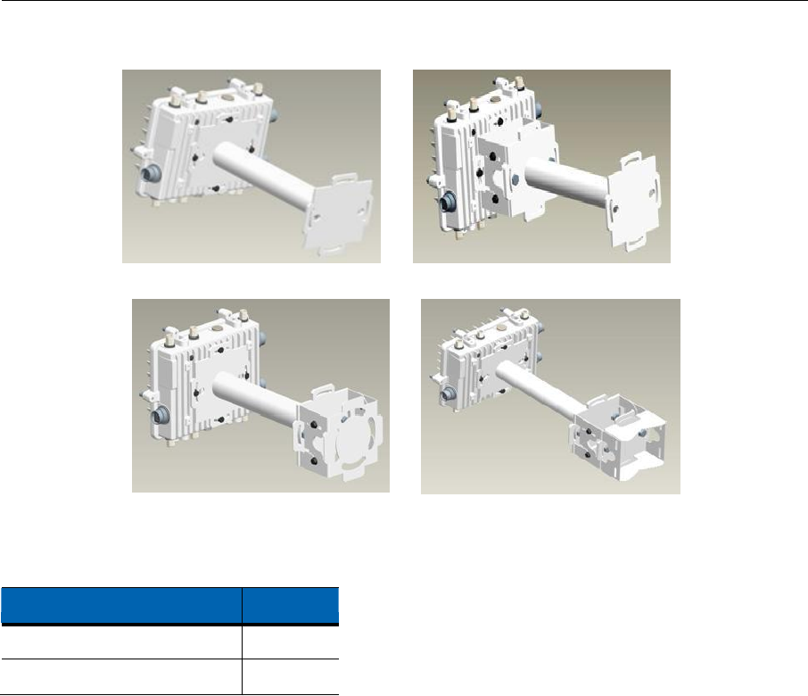
The extension arm kit can also be used in combination with the any of the brackets from the mounting bracket
kit:
The following ancillary hardware to attach the extension arm to the mounting bracket kit sections is included
in
the extension arm
kit:
Description
Quantity
1/2 inch hex head
nut
2
1/2 inch x 3/4 inch hex head
bolt
2

24
AP 7161
Access Point Installation Guide
Pole Mounted
Installations
The mounting hardware kit and extension arm can be used in various combinations to properly install the
AP
7161
on a pole. For poles of up to 3 inches in diameter, attach the pole mount bracket of the mounting hardware kit
at
the desired position on the pole using band clamps up to 3/4 inch width, or a 1/2 inch x 4 inch wide U-bolt and
nuts. For
poles greater than 3 inches in diameter, attach the pole mount bracket using band clamps.
CAUTION
Always mount the AP 7161 with the black gore
vent facing down.
NOTE
The U-bolt and band clamps are not included in the mounting bracket
kit.
NOTE
Use of the extension arm is recommended for installations on poles greater than 3
inches
in diameter.
AP 7161
Access Point Installation
Guide
25
Vertical
Pole
Mount
Use the following procedures for vertical pole mount installations. Use of the extension arm is recommended
when mounting the access point to poles greater than 3 inches
is diameter.
For poles up to 3 inches in diameter when using a
U-bolt
:
1.
Thread the two inner nuts onto the U-bolt. Place the U-bolt at the desired mounting
location.
2.
Place the pole mount bracket section on the U bolt. Adjust the inner nuts until the pole mount bracket section
is
against the pole and the U-bolt can be secured
tightly to the pole.
3.
Place the angle adapter bracket section on the U-bolt with the open slot connections on the bottom and align
it
with the pole mount section.
4.
Put the two
outer nuts on the U-bolt to attach the angle adapter bracket section to the pole mount bracket
section.
5.
Tighten all nuts to 300 inch pounds
(lbf-in).
6.
Position the access point bracket section so that the bottom of the section
with the straight (not bevel cut) side
is oriented toward the bottom side of the AP
with the gore vent. Using a torque wrench or a ratchet and a
10mm socket, or an adjustable wrench, attach (but don’t tighten) the access point bracket section to the AP
7161 with the with four M6 hex flange screws.
7.
Insert two M6 hex flange screws into the bottom holes on the sides of the access
point bracket section.
8.
With the access point positioned so that the gore vent is facing down, insert the two M6 hex flange screws
in
the bottom holes on the sides of the access point bracket section into the open slot connections on
the bottom
of the angle adapter bracket section.
9.
Rotate the access point bracket section upward and align the top holes on the sides
with the top holes on the
angle adapter bracket section. Insert two M6 hex flange screws into the top holes on
the angle adapter bracket
section.
10.
Use a torque wrench or a ratchet and a 10mm socket, or an adjustable wrench, to finish attaching the access
point bracket section to the angle adapter bracket section with the M6 hex flange screws in the open
slot
26
AP 7161
Access Point Installation Guide
connections and the top holes on the angle adapter bracket section. Do not tighten the screws
until all rotation
and
tilt
adjustments are complete.
11.
To adjust the position of the
access point, rotate the access point bracket section (plus or minus 15 degrees)
and
tilt
the angle adapter bracket section (up to 45 degrees).
12.
Tighten all hex flange screws to 60 inch pounds
(lbf-in).
For mounting
with band clamps:
1.
Attach the pole mount bracket section at the desired mounting location using band clamps.
2.
With the angle adapter bracket section positioned so that the open connector slots are on
the bottom, attach
the angle adapter bracket section to the pole mount bracket section using two 1/2 inch bolts and nuts. Tighten
the nuts to 300 inch pounds
(lbf-in).
3.
Position the access point bracket section so that the bottom of the section with the straight (not bevel cut)
sides is oriented toward the bottom side of the AP
with the gore vent. Using a torque wrench or a ratchet and a
10mm socket, or an adjustable wrench, attach (but don’t tighten) the access point bracket section to the AP
7161 with the with four M6 hex flange screws.
AP 7161
Access Point Installation
Guide
27
4.
Insert two M6 hex flange screws into the bottom holes on the sides of the access
point bracket section.
5.
With the access point positioned so that the gore vent is facing down, insert the two M6 hex flange screws
in
the bottom holes on the sides of the access point bracket section into the open slot connections on
the bottom
of the angle adapter bracket section.
6.
Rotate the access point bracket section upward and align the top holes on the sides
with the top holes on the
angle adapter bracket section. Insert two M6 hex flange screws into the top holes on
the angle adapter bracket
section.
7.
Use a torque wrench or a ratchet and a 10mm socket, or an adjustable wrench, to finish attaching the access
point bracket section to the angle adapter bracket section with the M6 hex flange screws in the open
slot
connections and the top holes on the angle adapter bracket section. Do not tighten the screws
until all rotation
and
tilt
adjustments are complete.
8.
To adjust the position of the access point, rotate the access point bracket section (plus or minus 15 degrees)
and
tilt
the angle adapter bracket section (up to 45 degrees).
9.
Tighten all hex flange screws to 60 inch pounds
(lbf-in).
To use the extension arm with the mounting hardware
kit
:
1.
Attach the pole mount section at the desired mounting location using a U-bolt or band clamps.
2.
Complete the steps for assembling and positioning the mounting bracket sections for
poles less than or greater
than 3 inches outlined above.
3.
Using a torque wrench or a ratchet and a 10mm socket, or an adjustable wrench, attach the extension arm
to
the access point bracket section with four M6
hex flange screws. Tighten the hex flange screws to 60 inch
pounds
(lbf-in).
4.
With the access point positioned so that the gore vent is facing down, attach the extension arm to the access
point with four M6 hex flange screws. Tighten the hex flange screws to 60 inch pounds
(lbf-in).
28
AP 7161
Access Point Installation Guide
Examples for using the extension arm alone, or
with the mounting bracket kit for a pole mount installation are
shown
below:
Wall
Mounted
Installations
For
wall mounted installations, use only the access
point bracket and angle adjust bracket sections.
CAUTION
Always mount the AP 7161 with the black gore
vent facing down.
NOTE
The U-bolt and band clamps are not included in the mounting bracket
kit.
NOTE
The lag bolts are not included in the mounting bracket
kit.
1.
With the open slot connections facing down, attach the angle adjust bracket section at the desired mounting
location using four #10/32 lag bolts.
AP 7161
Access Point Installation
Guide
29
2.
Using a torque wrench or a ratchet and a 10mm socket, or an adjustable wrench, attach (but
don’t tighten) the
access point bracket section to the AP 7161 with four M6 hex flange screws and insert two M6 hex
flange
screws into the bottom holes on the sides of the access
point bracket section.
3.
With the access point positioned so that the gore vent is facing down, insert the two M6 hex flange screws
in
the bottom holes on the sides of the access point bracket section into the open slot connections on
the bottom
of the angle adapter bracket section.
4.
Rotate the access point bracket section upward and align the top holes on the sides
with the top holes on the
angle adapter bracket section. Insert two M6 hex flange screws into the top holes on
the angle adapter bracket
section.
5.
Use a torque wrench or a ratchet and a 10mm socket, or an adjustable wrench, to finish attaching the angle
adapter bracket section to the access point bracket section with the four M6 hex flange screws in the open
slot
connections and the top holes on the angle adapter bracket section. Do not tighten the screws
until all rotation
and
tilt
adjustments are complete
6.
To adjust the position of the access point, rotate the access point bracket section (plus or minus 15 degrees)
and
tilt
the angle adapter bracket section (up to 45 degrees).
7.
Tighten all hex flange screws to 60 inch pounds
(lbf-in).
30
AP 7161
Access Point Installation Guide
To use only the extension arm
:
1.
Using four #10/32 lag bolts, attach the extension arm at the desired mounting
location.
2.
Using a torque wrench or a ratchet and a 10mm socket, or an
adjustable wrench, attach the mounting extension
arm to the access point with four M6 hex flange screws. Tighten the hex flange screws to 60 inch pounds
(lbf-in).
To use the extension arm with the mounting hardware
kit
:
1.
With the open slot connections facing down, attach the angle adjust bracket section at the desired mounting
location using four #10/32 lag bolts.
2.
Complete the steps for assembling and positioning the angle adapter bracket and access
point bracket sections
outlined above.
3.
With the access point positioned so that the gore vent is facing down, attach the extension arm to the access
point bracket section of the assembled mounting bracket already in position using four M6 hex flange screws.
Tighten the hex flange screws to 60 inch pounds
(lbf-in).
4.
Using a torque wrench or a ratchet and a 10mm socket, or an adjustable wrench, attach the extension arm
to
the access point with four M6 hex flange screws. Tighten the hex flange screws to 60 inch pounds
(lbf-in).
AP 7161
Access Point Installation
Guide
31
AP 7161 Power Options Using Power over Ethernet (PoE)
Power over Ethernet
(PoE)
is the power source for an AP 7161 access point. For optimal performance, an AP
7161
can be powered by the following Motorola Solutions injectors and
RFS
controllers that support 802.AT PoE.
For
installations requiring an outdoor
PoE
injector, the following Motorola Solutions options are recommended:
•
AP-PSBIAS-7161-US
•
AP-PSBIAS-7161-WW
The AP-PSBIAS-7161 is a 1-Port 802.3at PoE
Gigabit Ethernet injector. The injector is IP66
rated for outdoor
deployments when used with the weatherproof kit supplied.
There are two power cord options for the AP-PSBIAS-7161 models. The AP-PSBIAS-7161-US comes equipped
with
a cable with a standard three prong power plug. This plug can be removed by the installer
if
required
when
connecting to an AC source. The AP-PSBIAS-7161-WW comes equipped with a cable with open leads.
Mounting
kits are not supplied (see Outdoor PoE
Hardware and Mounting Accessories on page 9 for mounting
kit part
numbers).
NOTE
Product installation and mounting instructions are provided with the outdoor
power
injector. Refer to the AP-PSBIAS-7161
Install Guide.
If located within 100 meters of the controller and a
PoE
port is available, the AP 7161 access
point can also be
connected directly to one
of the following Motorola Solutions controllers:
•
RFS4000
•
RFS6000
•
RFS7000
•
NX9000
A standard CAT5E cable can be used to provide the connection to the AP 7161. The GE1/POE port on the AP
7161
is where the standard CAT5E cable
will connect to the access point and use of the weatherproof RJ45 plug kit
that
comes with the unit
will
maintain a weatherproof seal for outdoor
installation at the ethernet port.
If a CAT5E cable is used to connect the access point to an
RFS
controller through a building egress, a
suitable
lightning protection system should be considered. A professional installer should be consulted to identify an
appropriate system.
CAUTION
When using controllers, the total power limits for the AP
7161 must be considered.
The two radio configuration draws less power than a three radio configuration.
If
sufficient power is not available, the AP 7161 software
will
disable the third radio
and throttle back performance on all radio and Ethernet
interfaces.

32
AP 7161
Access Point Installation Guide
Basic AP 7161
Configuration
For
information on how use a Motorola Solutions
RFS
Series controller to manage an AP 7161 access
point, refer
to the Motorola Solutions WiNG 5 Access Point System Reference Guide at http://supportcentral.motorola.com.
NOTE
Only a trained installation professional should configure the AP 7161.
For FCC and ETSI
requirements, set the 2.4GHz radio gain to 8 dBi and set the
5GHz
radio gain to 10 dBi.
The configuration steps below apply to radio1, radio2 and, optionally, radio3.
Access Point Location
Configuration
Select outdoor or indoor placement of the transmitting antennas
ap71xx-XXXXXX (config-device-xx-xx-xx-xx-xx-xx-if-radio1)#placement outdoor
Note all indoor-only bands are disabled by the software
OR
ap71xx-XXXXXX (config-device-xx-xx-xx-xx-xx-xx-if-radio1)#placement indoor
Note all outdoor-only bands are disabled by the software
Antenna
Configuration
For the AP 7161
to operate properly, the antenna type and antenna gain must be configured. Select
antenna type with following command:
ap71xx-XXXXXX
(config-device-xx-xx-xx-xx-xx-xx-if-radio1)#service
antenna-type ap7161-dipole
Select antenna gain with following command:
ap71xx-XXXXXX
(config-device-xx-xx-xx-xx-xx-xx-if-radio1)# antenna-gain <units in dBi>
These changes can also be made in the device profile configuration
file.
Radio Channel and Power Configuration
ap71xx-XXXXXX
(config-device-xx-xx-xx-xx-xx-xx-if-radio2)#channel <number>
ap71xx-XXXXXX
(config-device-xx-xx-xx-xx-xx-xx-if-radio2)#power <units in dBm>
Only channels and power settings available in your regulatory domain and configuration will be allowed.
Automatic Channel Select
Override
Under certain conditions (e.g. the presence of a 40 MHz channel intolerant client or a legacy device on
the
extension channel), a radio which has been configured for 40 MHz channel operation may automatically select
the
20 MHz channel. To override or restore automatic channel selection, use the following commands:
ap71xx-XXXXXX
(config-device-xx-xx-xx-xx-xx-xx-if-radio1)#service
ignore-ch-width-mgmt
ap71xx-XXXXXX
(config-device-xx-xx-xx-xx-xx-xx-if-radio1)#no service
ignore-ch-width-mgmt
This change can also be made in the device profile configuration file.

AP 7161
Access Point Installation
Guide
33
Specifications
Hardware
Specifications
Operating Voltage
36-57 VDC
Operating Current
Not to exceed 750 mA@48 VDC
Power In (PoE)
PoE support inbound power - 802.3AT on GE1/POE
port
Ethernet Ports
2 Gigabit Ethernet ports
Dimensions (unit) mounted
28.1cm W x 21.8cx H x 9.4cm D (11.1" W x 8.6" H x 3.7" D)
Weight (Unit)
6.4 lbs
/
2.9 Kg
Mounting
Adaptable mounting kit for pole and wall deployments with optional extension arm accessory
LED
6 top mounted weatherized
LEDs
with multifunction read
Uplink
2 Gigabit Ethernet Ports (GE1/POE, GE2)
autosensing
Antenna Connectors
Outdoor rated N-Type connectors
Console Port
Outdoor rated RJ45 console
port
Hardware Reset
External
hardware reset button
Multi Band Security Sensor
Outdoor 24x7 Wireless Intrusion Prevention System (IPS)/Assurance Sensor
(SKU
AP-7161-66S40-US, AP-7161-66S40-WR)

34
AP 7161
Access Point Installation Guide
Environmental
Specifications
Operating Temperature -40 to +70 degrees
celsius
Storage Temperature -40 to +85 degrees
celsius
Operating Humidity 5-95 percent
Operating Altitude 8,000
feet
Storage Altitude 30,000
feet
Electrostatic Discharge
EN61000-4-2.
Air +/-15kV, Contact +/-8kV
Enclosure
Outdoor IP67
rated, corrosion resistant enclosure
ASTM B117
salt, fog, and rust resistance
Wind Ratings
150 mph
*
(unit bracket measurement)
Operational Shock
IEC60721-3-4, Class 4M3, MIL STD 810F
Operational Vibration IEC60721-3-4, Class
4M3
Radio
Specifications
Network Standards
IEEE
802.11 a/b/g/n, 802.11e, 802.11i, WPA2, WMM, and
WMM-UAPSD
Supported Data Rates
802.11b/g:1, 2, 5.5, 11, 6, 9, 12, 18, 24, 36, 48 and 54
Mbps
802.11a: 6, 9, 12, 18, 24, 36, 48 and 54
Mbps
802.11n: MCS 0-15 up to 300
Mbps
802.11n Support
3x3 MIMO with 2 spatial streams
20MHz and 40MHz channels supported
300Mbps data rates per radio
Packet
aggregation (AMSDU,AMPDU)
Reduced
interframe spacing
802.11
b/g/n
Operating frequency 2.4 - 2.483 GHz
Maximum
EIRP 32
dBm
*
802.11
a/n
Operating frequency 4.940 GHz - 4.990 GHz and 5.25 GHz - 5.35 GHz and 5.470 GHz - 5.825 GHz
Maximum
EIRP 34
dBm
*
*Maximum
EIRP may vary based on local standards for the area of deployment.

AP 7161
Access Point Installation
Guide
35
Networking and Software
Specifications
Security
Stateful Firewall,
IP
filtering, NAT, 802.1X, 802.11i WPA2, WPA
24x7 Dual band sensor capabilities
*
(subject to software license keys and sensor radio SKU)
Advanced
forensics
Connectivity troubleshooting
Wireless Intrusion Prevention
LiveRF
Quality of Service (QoS)
WMM, WMM-UAPSD, 802.1p, Diffserv and TOS
Routing
Layer 3 routing, 802.1q/p, DynDNS,
DHCP
server/client,
BOOTP Client,
PPPoE
and LLDP
Approvals
Radio*
FCC Title 47, part 15, part 90; EN
301 489-17
EN 301 893, v1.5.1 DFS;EN
300 328
Industry Canada; China SRRC
Australia/New Zealand
Safety*
UL 60950-1, -22; CSA C22.2
No.60950-1-07, -22
CB-IEC 60950 -1, 22; EN
60950-1:2006+ A11:2009
RoHS/WEEE/CMM; CE
*
For more country specific regulatory information, please contact Motorola Solutions or your
authorized
partner.
Warranty
•
One (1) year on AP
7161 hardware (accessories not included)
•
(30)
day on accessories
•
(90) day on
software

36
AP 7161
Access Point Installation Guide
Basic Troubleshooting
Basic troubleshooting recommendations for the AP 7161 access
point are listed in the following table:
Indication
Response
LEDs are not
lit
No power to device:
•
Verify 802.3at compatible source is connected via PoE
•
Verify AC source to PoE
injector
•
Unit was configured with
LEDs
disabled
No Ethernet connectivity
to this unit
No Ethernet connectivity
to this unit
No wireless connectivity
to this unit
No wireless connectivity
to this unit

AP 7161
Access Point Installation
Guide
37
Regulatory
Compliance
This device is approved under the Symbol Technologies, Inc. brand. Symbol Technologies, Inc. is a
wholly owned
subsidiary of Motorola Solutions, Inc. (collectively
“Motorola”).
All Motorola Solutions devices are designed to be compliant with rules and regulations in locations they are sold
and
will
be labeled as required. Any changes or modifications to Motorola Solutions equipment, not expressly
approved by
Motorola Solutions, could void the user's authority to operate the equipment.
Local language translations are available at the following
website:
http://supportcentral.motorola.com
Motorola Solutions devices are professionally installed, the Radio Frequency Output Power
will
not exceed
the
maximum allowable limit for the country
of operation.
Antennas: Use only the supplied or an approved replacement antennas. Unauthorized antennas,
modifications, or
attachments could cause damage and may
violate regulations.
FCC Approval
Statement
Federal Communications Commission
Office of Engineering and Technology
Laboratory
Division
Interim Plans to Approve UNII Devices Operating in the 5470
-
5725
MHz Band with Radar Detection
and DFS
Capabilities
The FCC,
NTIA, FAA and industry are working to resolve interference to Terminal Doppler Weather Radar (TDWR)
systems used near airports that has occurred from some outdoor wireless systems operating in the 5470 MHz
–
5725 MHz band. These wireless devices are subject to Section 15.407 of our rules and when operating as a
master device they are required to implement radar detection and
DFS
functions. We are continuing our work
to
develop long-term equipment authorization test procedures that will ensure that the devices comply with our
rules
that include protecting the TDWR operations. In the interim, the Commission
will
now allow certification
of
wireless master devices with radar detection function and with
DFS
capability,
if
they meet the
following
conditions:
1. Devices
will
not transmit on channels which overlap the 5600 – 5650 MHz band.
1
2. Devices intended for outdoor use
will
be further restricted, as
follows:
•
Devices must be professionally installed when operating in the 5470 – 5725 MHz band.
2
•
Grantees must provide owners, operators and all such installers with
specific instructions in their user’s
manual on requirements to avoid interference to TDWRs and information that meets the
following
instructions:
• Any installation of either a master or a client device within 35 km of a TDWR location shall be separated
by at least 30 MHz (center-to-center) from the TDWR operating frequency 3, 4, and 5.

38
AP 7161
Access Point Installation Guide
1
The devices subject to the requirements in this KDB can select the initial channel for operation to avoid TDWRs
and apply the Uniform Channel Spreading requirements (see
FCC 06-96 in ET
Docket 03-122 released June 30,
2006) on the remaining available frequency band of operation. All the other test procedures including the
test
radar patterns remain the same at the present time. A revision to the measurement procedure
with modification
to the Uniform Channel Spreading requirement and other changes
will
be released in the future. The
Commission
will
also address the issue of any field upgrade option at that
time.
2
The grantee must identify the specific expertise and the training required by
the installers for installing these
types of devices.
3
In some instances
it
is possible that a device may be within 35 km of multiple TDWRs. In this
case the device
must ensure that
it
avoids operation within 30 MHz for each of the TDWRs. This requirement applies even
if
the
master is outside the 35 km radius but communicates with outdoor clients which may be within the 35 km
radius of the TDWRs.
4
The requirement for ensuring 30 MHz frequency separation is based on the best information available to date.
If
interference is not eliminated, a distance limitation
based on line-of-sight from TDWR
will
need to be used. In
addition, devices with bandwidths greater than 20 MHz may require greater frequency separation.
•
Procedures
for the installers and the operators on how to register the devices in the industry-sponsored
database with the appropriate information regarding the location and operation of the device and
installer
information is
included.
6
•
Devices must meet all of the other requirements specified in Section 15.407, and
it
is prohibited to include
configuration controls (e.g. country code settings or other options to modify
DFS functions) to change
the
frequency of operations to any frequency other than those specified on the grant of certification for US
operation.
7
•
All applications for equipment authorization must clearly show compliance
with all of the technical
requirements under worst case parameters, under user or operator control, based on frame rates,
listen/talk
ratios and user
data transfer conditions.
All the devices subject to the DFS
requirements must be submitted to the Commission’s Laboratory Division
for
pre-grant testing and equipment authorization.8 The applicant must ensure
that all equipment authorization
applications subject to this interim procedure include appropriate attestations that the device has no option
to
change the DFS
parameters and that transmissions are disabled at least in the 5600 – 5650 MHz band. The
application must include the user’s manual with the appropriate installation and operations requirements
for the
installers and operators.
We are continuing to evaluate additional measures that may need to be taken to further ensure
against
interference caused by 5
GHz
outdoor wireless systems located near airports. While manufacturers have an
obligation to ensure that their equipment complies with
FCC
rules, and must take steps to ensure their devices are
unlikely to cause harmful interference, Section 15.5 of the Commission’s rules also places an obligation on users
of devices to avoid causing interference and to correct any interference that may occur.

AP 7161
Access Point Installation
Guide
39
We encourage the manufacturers to include information for the users, including the operators and installers,
to
ensure that they understand that
it
is incumbent on them to cooperate with manufacturers to implement any
changes necessary
to facilitate compliance.
5
Devices may be optionally designed not to transmit on channels which overlap 5570 – 5680 MHz instead
of
requiring installers to perform site-by-site adjustments. In that case
it
is still required that the devices should be
installed professionally and the procedures
for registering the device in the industry database should be included
in the Users
Manual.
6
A voluntary WISPA sponsored database has been developed that allows operators and
installers to register the
location information of the UNII devices operating outdoors in the 5470 – 5725 MHz band within 35 km of any
TDWR location (see
http://www.spectrumbridge.com/udia/home.aspx).
This database may be used
by
government
agencies in order to expedite resolution of any interference to TDWRs.
7
For
example, device software must not have any country code options or software configuration settings
which
allow an end user to modify the DFS
operation or impact the performance of
DFS. See KDB
594280.
8
The TCBs are not permitted to
approve transmitters with
radar detection capabilities. See KDB
628591.
9
The manufacturers may consider taking steps providing clear instructions to operators and installers of devices
as to the need to comply with rules for use of the band, guidance on registration of devices and any other
processes that are designed to avoid interference. They may use methods that include, but are not limited
to,
instructions in manuals, notification on product web pages and service bulletins issued for products in the
field.
TDWR Location
Information
STATE
CITY
LONGITUDE
LATITUDE
FREQUENCY
TERRAIN
ELEVATION
(MSL) [ft]
ANTENNA
HEIGHT
ABOVE
TERRAIN [ft]
GA
ATLANTA
W 084 15 44
N 33 38 48
5615 MHz
962
113
IL
MCCOOK
W 087 51 31
N 41 47 50
5615 MHz
646
97
IL
CRESTWOOD
W 087 43 47
N 41 39 05
645 MHz
663
113
IN
INDIANAPOLIS
W 086 26 08
N 39 38 14
5605 MHz
751
97
KS
WICHITA
W 097 26 48
N 37 30 26
5603 MHz
1270
80
KY
COVINGTON
W 084 34 48
N 38 53 53
5610 MHz
942
97

40
AP 7161
Access Point Installation Guide
S
T
A
T
E
CITY
LONGITUDE
LATITUDE
FREQUENCY
TERRAIN
ELEVATION
(MSL) [ft]
ANTENNA
HEIGHT
ABOVE
TERRAIN [ft]
KY
LOUISVILLE
W 085 36 38
N 38 02 45
5646 MHz
617
113
LA
NEW ORLEANS
W 090 24 11
N 30 01 18
5645 MHz
2
97
MA
BOSTON
W 070 56 01
N 42 09 30
5610 MHz
151
113
MD
BRANDYWINE
W 076 50 42
N 38 41 43
5635 MHz
233
113
MD
BENFIELD
W 076 37 48
N 39 05 23
5645 MHz
184
113
MD
CLINTON
W 076 57 43
N 38 45 32
5615 MHz
249
97
MI
DETROIT
W 083 30 54
N 42 06 40
5615 MHz
656
113
MN
MINNEAPOLIS
W 092 55 58
N 44 52 17
5610 MHz
1040
80
MO
KANSAS CITY
W 094 44 31
N 39 29 55
5605 MHz
1040
64
MO
SAINT LOUIS
W 090 29 21
N 38 48 20
5610 MHz
551
97
MS
DESOTO
COUNTY
W 089 59 33
N 34 53 45
5610 MHz
371
113
NC
CHARLOTTE
W 080 53 06
N 35 20 14
5608 MHz
757
113
NC
RALEIGH
DURHAM
W 078 41 50
N 36 00 07
5647 MHz
400
113
NJ
WOODBRIDGE
W 074 16 13
N 40 35 37
5620 MHz
19
113
NJ
PENNSAUKEN
W 075 04 12
N 39 56 57
5610 MHz
39
113
NV
LAS VEGAS
W 115 00 26
N 36 08 37
5645 MHz
1995
64
NY
FLOYD
BENNETT
FIELD
W 073 52 49
N 40 35 20
5647 MHz
8
97
OH
DAYTON
W 084 07 23
N 40 01 19
5640 MHz
922
97
OH
CLEVELAND
W 082 00 28
N 41 17 23
5645 MHz
817
113
OH
COLUMBUS
W 082 42 55
N 40 00 20
5605 MHz
1037
113
OK
AERO. CTR
TDWR
#1
W 097 37 31
N 35 24 19
5610 MHz
1285
80

AP 7161
Access Point Installation
Guide
41
STATE
CITY
LONGITUDE
LATITUDE
FREQUENCY
TERRAIN
ELEVATION
(MSL) [ft]
ANTENNA
HEIGHT
ABOVE
TERRAIN [ft]
OK
AERO. CTR
TDWR
#2
W 097 37 43
N 35 23 34
5620 MHz
1293
97
OK
TULSA
W 095 49 34
N 36 04 14
5605 MHz
712
113
OK
OKLAHOMA CITY
W 097 30 36
N 35 16 34
5603 MHz
1195
64
PA
HANOVER
W 080 29 10
N 40 30 05
5615 MHz
1266
113
PR
SAN JUAN
W 066 10 46
N 18 28 26
5610 MHz
59
113
TN
NASHVILLE
W 086 39 42
N 35 58 47
5605 MHz
722
97
TX
HOUSTON
INTERCONTL
W 095 34 01
N 30 03 54
5605 MHz
154
97
TX
PEARLAND
W 095 14 30
N 29 30 59
5645 MHz
36
80
TX
DALLAS LOVE
FIELD
TX
LEWISDALE
DFW
W 096 58 06
N 32 55 33
5608 MHz
541
80
W 096 55 05
N 33 03 53
5640 MHz
554
31
UT
SALT LAKE CITY
W 111 55 47
N 40 58 02
5610 MHz
4219
80
VA
LEESBURG
W 077 31 46
N 39 05 02
5605 MHz
361
113
WI
MILWAUKEE
W 088 02 47
N 42 49 10
5603 MHz
820
97113
Wireless Country
Approvals
Regulatory markings are applied to the device signifying the radio(s) are approved for use
in the following
countries: United States, Canada, Australia, and Europe.
Please refer to the Declaration of Conformity
(DoC) for details of other country markings. This is available
at:
http://www
.motorola.com/doc
.
Note 1
: For 2.4 GHz Products: Europe includes, Austria, Belgium, Bulgaria, Czech Republic, Cyprus,
Denmark,
Estonia, Finland, France, Germany, Greece, Hungary, Iceland, Ireland, Italy,
Latvia, Liechtenstein, Lithuania,
Luxembourg, Malta, Netherlands, Norway, Poland, Portugal, Romania, Slovak Republic, Slovenia, Spain,
Sweden,
Switzerland and the United Kingdom.
Operation of the device without regulatory approval is
illegal.

42
AP 7161
Access Point Installation Guide
Health and Safety Recommendations
The Federal Communications Commission
(FCC)
with its action in ET
Docket 96-8 has adopted a safety standard
for human exposure to radio frequency
(RF)
electromagnetic energy emitted by
FCC
certified equipment.
Motorola
Solutions products meet the uncontrolled environmental limits found in
OET-65
and ANSI C95.1, 1991. Proper
operation of this radio according to the instructions found in this manual
will
result in user exposure that
is
substantially below the
FCC
recommended
limits.
Warnings for the Use of Wireless
Devices
Please observe all warning notices with
regard to the usage of wireless devices.
Potentially Hazardous Atmospheres
You are reminded of the need to observe restrictions on the use of radio devices in fuel depots, chemical
plants
etc. and areas where the air contains chemicals or particles (such as grain, dust, or metal powders).
Safety in
Hospitals
Wireless devices transmit radio frequency energy and may affect medical electrical equipment. When
installed
adjacent to other equipment,
it
is advised to verify that the adjacent equipment is not adversely
affected.
RF Exposure
Guidelines
Safety
Information
The device complies
with internationally recognized standards covering human exposure to electromagnetic
fields
from radio devices.
Reduce RF Exposure
-
Use
Properly
Only operate the device in accordance
with the instructions supplied.
Remote and Standalone Antenna Configurations
To comply with
FCC RF
exposure requirements, antennas that
are mounted externally at remote locations or
operating near users at stand-alone desktop of similar configurations must operate with a minimum separation
distance of 28 cm from all persons.
Power
Supply
Use only a power-over Ethernet 802.3at compliant solution. The required power rating is 25.5
Watts.
Wireless Devices
- Countries
Country
Selection
Select only the country in which you are using the device. Any other selection
will
make the operation of
this
device
illegal.

AP 7161
Access Point Installation
Guide
43
Operation in the
US
The available channels for 802.11 b/g operation in the US are Channels 1 to 11. The range of channels is
limited
by
firmware.
The FCC
requires that the
FCC
ID label be placed on the outside of the device. If the device is placed in a
protective enclosure that requires tools to
access, a permanent label with
FCC
ID must be placed on the exterior
of
the protective enclosure
Radio Frequency Interference Requirements
-
FCC
This equipment has been tested and found to comply with the limits for a Class B
digital device,
pursuant to Part 15 of the
FCC
rules. These limits are designed to provide reasonable
protection
against harmful interference in a residential installation. This equipment generates, uses and
can radiate radio frequency energy and,
if
not installed and used in accordance
with the
instructions, may cause harmful interference to radio communications. However there is no guarantee
that
interference
will
not occur in a particular installation. If this equipment does cause harmful interference to radio
or television reception, which can be determined by turning the equipment off and on, the user is encouraged
to
try to correct the interference by one or more of the following measures:
•
Reorient or relocate the receiving antenna
•
Increase
the separation between the equipment and receiver
•
Connect the equipment into an outlet on a circuit different from that to which the receiver is connected
.
•
Consult the dealer or an experienced radio/TV technician for help.
Radio Transmitters (Part 15)
This device complies with Part 15 of the
FCC
Rules. Operation is subject to the following two conditions:
(1)
this
device may not cause harmful interference, and (2)
this device must accept any interference received, including
interference that may cause undesired operation.
Radio Frequency Interference Requirements
- Canada
This Class B digital apparatus complies with Canadian ICES-003.
Cet appareil numérique de la classe B est conforme à la norme NMB-003 du Canada.
Devices using the 5.470 – 5.725 GHz
band shall not be capable of transmitting in the 5.60-5.65
GHz band
in
Canada, make sure that Canada is the country selected during setup to ensure
compliance.
Radio
Transmitters
This device complies with RSS 210 of Industry & Science Canada. Operation is subject to the
following
two
conditions: (1)
this device may not cause harmful interference and
(2) this device must accept any
interference
received, including interference that may cause undesired operation.
To reduce potential radio interference to other users, the antenna type and its gain should be so chosen
that the
equivalent isotropically radiated power
(EIRP)
is not more than that permitted for successful communication.

44
AP 7161
Access Point Installation Guide
This device has been designed to operate with the antennas listed in this guide, and having a maximum gain of 8
dBi (2.4 GHz) and 10 dBi (5 GHz)
for radios one and two. Antennas not included in this list, or having a gain greater
than 8 dBi (2.4 GHz) and 10 dBi (5 GHz)
for radios one and two, are prohibited for use with this device. This device
has been designed to operate with the antennas listed in this guide, and having a maximum gain of 4.5 dBi (2.4
GHz) and 7.5 dBi (5 GHz)
for radio three. Antennas not included in this list, or having a gain greater than 4.5 dBi
(2.4 GHz) and 7.5 dBi (5 GHz)
for radio three, are strictly prohibited for use with this device. The
required antenna
impedance is 50 ohms.
Label Marking: The Term "IC:"
before the radio certification signifies that
Industry Canada
technical specifications
were met.
This device has been designed to operate with the antennas listed in the Enterprise Wireless LAN Antenna
Specification Guide. Refer to the guide at http://supportcentral.motorola.com.
CE
Marking
and European Economic Area
(EEA)
The use of 2.4 GHz RLAN’s, for use through the EEA,
have the following
restrictions:
•
Maximum radiated transmit power of 100 mW
EIRP
in the frequency range 2.400 -2.4835 GHz
•
France outside usage, the equipment is restricted to 2.400-2.45
GHz
frequency range.
•
Italy requires a user license for outside usage
Statement of
Compliance
Motorola Solutions hereby declares that this device is in compliance with the essential requirements and
other
relevant provisions of Directive 1999/5/EC. A Declaration of Conformity may be
obtained from
http://www
.motorola.com/doc
.
Other Countries
Australia
Use of 5 GHz RLAN’s
in Australia is restricted in the following band: 5.50 – 5.65 GHz.
Brazil
Regulatory Declarations for AP 7161 - BRAZIL
Note: The certification mark applied to the
AP 7161
is for Restrict Radiation Equipment. This equipment operates
on a secondary basis and does not have the right for protection against harmful interference from other users
including same equipment types. Also this equipment must not cause interference to systems operating on a
primary basis.
For
more information consult the website www.anatel.gov
.br

AP 7161
Access Point Installation
Guide
45
Declarações Regulamentares para AP
7161
- Brasil
Nota: A marca de certificação se aplica ao Transceptor, modelo AP 7161. Este equipamento opera em
caráter
secundário, isto é, não tem direito a proteção contra interferência prejudicial, mesmo de estações do mesmo
tipo,
e não pode causar interferência a sistemas operando em caráter primário. Para
maiores informações sobre
ANATEL consulte o site: www
.anatel.gov
.br
Chile
Este equipo cumple con la Resolución No 403 de 2008, de la Subsecretaria de telecomunicaciones, relativa a
radiaciones electromagnéticas.
This device complies with the Resolution Not 403 of 2008, of the Undersecretary of telecommunications,
relating
to electromagnetic
radiation.
Mexico
Restrict Frequency Range to: 2.450 – 2.4835 GHz.
T
aiwan
NOTICE!
According to: Administrative Regulations on Low Power Radio Waves Radiated Devices
Article 12
Without permission granted by the
DGT, any company, enterprise, or user is not allowed to
change frequency,
enhance transmitting power or alter original characteristic as well as performance to a approved
low power
radio-frequency devices.
Article 14
The low power radio-frequency devices shall not influence aircraft security and interfere with
legal
communications; If found, the user shall cease operating immediately until no interference is achieved. The
said
legal communications means radio communications are operated in compliance with the Telecommunications
Act.
The
low power radio-frequency devices must be susceptible with the interference from legal communications or
ISM radio wave radiated devices.
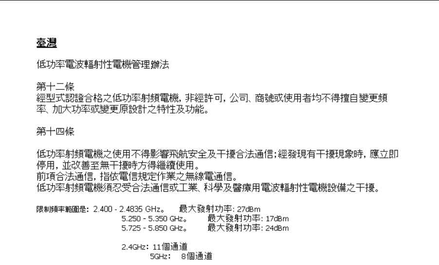
46
AP 7161
Access Point Installation Guide
Wireless device operates in the frequency band of 5.25-5.35
GHz,
limited for indoor use only.
在 5.25-5.35 秭赫頻帶內操作之無線資訊傳輸設備,限於室內使用

AP 7161
Ace
ess
Point
I
nsta
II
ation
Guide 47
1[
Waste Electrical
and Electronic WEEE
English:
For
E
U
Cus
t
omers:
A
ll
products
at the end or their
tile
must be
returned
to
Mo
t
o
r
o
l
a
for
r
ec
y
c
li
n
g
.
For
info
r
mat
i
o
n
on how
to return pr
od
uc
t,p
l
ea
s
e
go
t
o
:
h
ttp
:
//www
.
sy
mb
ol
.co
m/erw
ironm
enta
l_
c
o
m
p
li
a
nce
.
Bulgallsh:
3
a
Kll
"
C
>rr
H
OT
EC:
C
n
o
A
p
a
•
Ha
no
n
c
3
"""
MM
>K«O
O
T
B
C
OIY
K" npoAYKT"
T
p
•6
ua
Aa ce BPbiJiaT Ha
Mo
t
o
ro
l
a
3a
p
e
[IHKilMpa
H
e
.
3a
l1
H
r:j
)
O
pMa
[
l
l1
OT
H
OCH
O
BP
b
iJia
HeTO
Ha
np
OAY
KT
I1
,
MOnSOT>1AeTe
Ha
a
A
pec
:
http
:
//
ww
w
.
s
ym
bo
t.co
m
/
w
eee
ti
nk
.
tei1fna:
Pro
z
a
kazn
i
ky
z
E
U
:
V
sech
n
y
produkty je nutne po
s
ko
n
cen
f
jej
i
ch
z
ivo
t
nos
ti
vralit
spo
t
ec
n
o
s
t
i
Mot
or
o
l
a
k
r
ec
y
k
t
ac
i
.
t
nf
o
rma
c
e
o
zpusobu
vrace
n
i
produktu
najdete n
a
webove
s
t
ran
c
e
:
h
t
t
p
://w
ww
.
s
ymb
o
t
.
com/
cn
viro
nm
c
n
ta
t_
comp
i
t
anco
.
Danek:
T
i
t
kunder
i
E
U
:
A
tt
e
produkter
sk
a
t
re
l
u
r
ne
r
es
l
i
t
Mo
t
oro
l
a
l
i
t
rec
i
rk
u
t
e
ri
n
g
,
nar
de
er
udtjent.
L
<
e
s
op
t
ysn
i
nge
rn
e
om
returnering
at produkter
p
\
;
:
h
lt
p
:/!
www
.
s
y
mbo
t.c
om/
env
ir
onmen
t
al_
co
m
p
li
a
nce
.
Deulldl
;
Fur
K
u
nd
en
i
nn
e
rh
a
l
b
der
E
U:
Aile Produkte mussen
am
Ende
i
hrer
Lebensdaue
r
zum Recycling
an
Mo
to
ro
l
a
zuri)ckgcsandt wo
r
de
n
.
I
n
f
or
m
a
t
i
o
nen
zur
Rilcksendung
v
on
Produkten
i
n
den
Sie
unter
htt
p
:
//
www
.
s
y
mb
o
t.
c
o
m
/
en
v
ir
onmen
t
a
l_
co
mp
li
anc
e
.
E
eatl:
EL
k
li
en
t
id
c
l
c
:
koik
tooted t
u
l
cb
ncndc
c
l
uc
a
l
oppcdes
t
ag
as
t
ada
ta
a
sk
a
su
t
a
m
i
se
eesmargil
Moto
ro
l
a
i
'
l
e
.
Lisa
i
nf
o
rma
t
s
i
oon
i
s
aa
m
i
s
ek
s
t
oo
t
e
ta
gasta
mis
e
kohta
k
li
l
a
stag
e
pa
l
un
aadressi:
h
l
t
p
:
//w
w
w
.
sy
rnb
ol
.com
/env
i
r
onrnent
a
l_
co
rnpli
a
n
ce
.
Espallol
:
l"ara
c
li
e
nt
es
en
Ia
U
n
i
on
E
ur
o
p
ea:
todos
l
o
s
productos deben\n entregarse
a
Mo
t
or
o
l
a
a
t
fina
l
de su
c
i
clo
de
v
i
da
para que sean
re
cic
l
ados
.
S
i
desea
mas
i
nfo
r
mac
i
on
sobre como
d
ov
o
l
vc
r
un
pr
o
d
uc
t
o,
v
i
si
t
o:
h
tl
p
:
//
w
ww
.
s
y
mbo
l.c
om/cnv
i
ronm
cnt
a
t_
comp
li
ance
.
EM,
r
K
6
!
r
l<
l
m
A
u
rr.<
;
OTI]V
E
.
E.
:
0
Aa
T
U
n
po'i
6
VTO
,
OTO
r
t
Ao<;
Tl]<;
6
1
irpKt
i
U
<;
W
<;
T
O
U
<;,
n
pt
m
l
vo
t
TTI
OT
Pt
<PO
V
TOI
OTI]V
Moto
ro
l
a
V
I
O
OVOKUK
M
oq
.
r
,
a
TTt
P
I
OO
C
IT£Pt
<;
n
l
\
q
p
O
<P
O
P
i
t<;
oxcnK
a
t
rqv
cmorpo<P
tv6
<;
npo
i
'
6VTo<;
,
cmo
K
t
<P
9dTt
rq
o
1
cuauvo
l]
http
://ww
w
.
s
ym
bo
l
.
c
o
m
/en
vi
ronment
a
l_
comp
l
ianc
e
mo
C.
u
:r
oiKruo
.
F
l811981s
:
Clients
de
!
'
Un
i
on
Europeenne
:
Tous
l
e
s
p
r
o
d
u
i
s en fin
de
c
y
c
l
e
de
v
i
e
d
o
i
vent
etre retournes
il
Moto
ro
l
a
pour r
ecyc
l
ag
e
.
I"
our
cl
e
plus
amp
i
e
s
i
nfo
r
ma
tio
n
s
sur
l
e
r
e
t
our
de
prod
u
i
ts
,
c
ons
u
l
te
z
:
htt
p
:
/r
\w..w
.
symb
ol
.com
/env
i
r
onmen
t
a
l_
oo
m
p
li
an
ce
.
Italiano:
per
i
c
li
e
n
ti
d
e
ii
'U
E
:
tutli
i
p
r
o
doll
i
che
sono
giu
nt
i
a
t
t
erm
i
ne
de
l
rispettivo
c
ic
l
o
d
i
v
i
ta
devono
essere
r
e
s
t
i
t
u
i
ti a
Moto
r
o
l
a
a
l
fine
d
i
consentirne
il
ri
c
i
cla
gg
i
o
.
P
e
r
i
n
f
orma
z
i
on
i
sulle
moda
li
la
d
i
res
t
!
u
z
i
on
e
,
v
l
silare
il
seguente
s
i
lo
W
eb
:
h
tt
p
:
//w
w
w
.
sy
mb
ol
.com/
environmental_compliance.
Latvletu:
ES
k
li
e
n
ti
e
m
:
v
i
s
i
pr
o
duk
t
i
pee
to
ka
l
pos
an
a
s
miiza
be
i
gam
i
r
janogiida
atpak
a
l
M
o
t
oro
l
a
o
t
rre
i
zeja
i
p
a
rs
td;id
e
i
.
L
a
i
i
egu
t
u
i
n
f
o
rm
ac
i
j
u
par
produktu
no
g
a
d
iiila
nu
M
oto
r
o
l
a
,
l
licl
zu
,
skat et:
http://
www
.
s
ym
bo
l
.
co
m
/
e
nv
i
ro
nmen
t
a
l_
c
o
m
p
li
anc
e
.

48
AP 7161
Ace
ess
Point
I
nsta
II
ation Guide
Lletuvt t=
ES vartoto
j
ams:
vis
i
gaminiai
,
pas
i
ba
i
gus
i
ll
eksp
l
oa
t
ac
ij
os
l
a
i
kui
,
turi
b
Ot
i
g
r
z
i
n
t
i
u
t
il
i
zuoti
i
k
ompan
ij
<t
Motor
o
l
a
"
.
Daug
i
au
i
nfo
m
ac
i
j
os,kai
p
g
r
q:Zi
n
t
i
ga
m
in
,
i
ra
s
ite
:
htlp
:
//www
.
sy
m
bo
l
.
com/c
n
v
l
r
onmon
l
a
l_
co
mpli
a
n
c
e
.
Magyar:
Az EU-ban va
sar
1
6
k
nak
:
M
i
nde
n
tonkremenlterm<lket
a
Mo
t
o
r
o
l
a
vall
a
l
a
t
h
oz
kc
ll
e
l
jutta
t
n
i
(r
jrahasznos
i
ta
s
celjab61.
A
termek v
i
ss
zaj
utta
tasana
k
m
6dj
ava
l
k
apcs
o
l
atos
t
udniva
l
6
ker
t
l
a
t
ogasso
n
e
l
a
hll
p
:
//www
.
syrnb
ol
.
com
/
env
ironm
e
n
ta
l_
co
rnpl
ia
n
ce
we
b
o
l
da
l
r
a
.
Mall:
Gi1a
l
klijen
t
i
1
1-
UE:
i
l-prodotti
kollha
li
jk
un
u
was
l
u
fl-alinar
tal-najja
ta'1-uzu
t
aglihom,
iridu jigu
rr
i
tornat
i
gnand
Mo
t
oro
l
a
ghar
-ri
c
i
kl
agg
.
Gh
a
l
aktar taghrif dwar
kif
ghandek
tir
ri
torna
1-
pro
doll
,
jekk
j
og
T1g
bok
:Z
u
r
:
h
llp
:
//www
.
sy
mbol.co
rnl
cnv
i
ro
nmcn
l
a
l_
cornp
li
ancc
.
Nedeflanda:
Voor
k
l
an
t
en
i
n
de
E
U
:
a
il
e
producten
d
i
ene
n
aan het eincle van
h
un
l
even
sdu
ur
naar Motor
o
l
a
te worden teruggezonden voor
r
ecycling
.
R
aadp
l
eeg
htlp
:
/
/www
.
s
y
m
bo
l
.
co
m
/
environmental_compliance
voor meer
informatie
over het
l
erugzenden
van
p
rod
uc
te
n
.
Polski
:
Kl
ienc
i
z
obszaru
Unii
E
urop
e
j
ski
e
j
:
Produ
k
ty
wycofane z
eksploatacjinalei:y
zwr6c
i
c
do
fi
n
ny
Motorola w
c
·
e
lu
i
ch
ut
y
li
zacj
i.
I
nf
onnacje
na ternat zwrotu produkt6w
znajd
ujq
sina
stronic
i
n
t
ernctowc
j
h
ttp://www
.
s
y
mb
o
l
.
co
m
/
cn
v
i
ro
nrn
cnt
a
l_
comp
l
iancc
.
p
Pa
r
a
c
l
ientes
da
U
E
:
todos OS
produtos
no
fim
de v
i
da
devem ser devo
l
vidos
a
Mot
oro
l
a
para
re
c
i
clagern
.
Para obter
i
nfo
rrn
ao;6
es
sobre
como
devo
l
ve
r
o
p
r
odu
t
o,
v
i
sit
e
:
htlp
:
//www
.
syrnbo
l
.
com/c
n
v
i
r
onm
e
n
t
a
l_
co
mplianc
o
.
RomAnesc
:
Pentru
clien
i
din
UE
:
Toate
produse
l
e,
l
a
s
t
ar
i
t
u
l
duratei
l
o
r
de
fu
n
c\
i
o
n
are
,
trebuie rcturnatc
Ia
Motor
o
l
a
pcntru
rcc
icl
are
.
P
cnt
ru
i
n
f
o
rm
a
ii
despre
rcturnarea
p
r
odus
ulu
i,
a
ccesa
\
i
:
hNp:/!Y.ww
.
symbo
l
.
co
rn/weeelink
.
Slovensld
:
Z
a
kupce v EU:
vsi
izd
e
l
k
i
se morajo po poteku
Zivljenjske
dobe vrnit
i
p
od
j
etju
Mo
t
oro
l
a
za
rec
i
k
l
azo
.
Za
i
n
forrnac
i
j
e
o
vra
c
ilu
i
zde
l
ka
o
bis
c
ite
:
htt
p
:
/
/WY.w
.
syrnbol.com/
e
n
v
ir
on
men
t
a
l
_
co
mpli
a
n
c
e.
SlclveOOtna:
Pre
zakazn
f
kov
z kr
aj
i
n
E
U
:
Vsctky vyrobky
m
us
i
a
b
y
l
'
po up
l
ynu
tf
doby
i
c
h
zivotnosti vratene
s
p
o
l
ocno
st
i
Mo
t
oro
l
a na
r
ecyk
l
ac
i
u
.
B
li
zs
i
e
in
fonna
c
i
e
o
vra
t
en
i
vyrobkov
nirjdete
na
:
ht
tp
:
//Y,
ww
.
sy
mb
ol
.
G'O
rn/env
ir
onmen
t
a
l_
comp
li
ance
.
Suomi
:
As
iakk
nat
Euroopan unionin alueella:
Kaikki
t
uottee
t
on
palautettava
kierratettavnksi
M
o
t
oro
l
a-
yh
t
ioon
,
kun
tuotetta e
i
enaa
k
ay
t
e
t
a
.
Lisatietoja tuotteen
pa
l
auttarnisesta
on
osoiNeessa http://ww
w
.
sy
mb
o
l
.
co
m/e
nvir
on
me
n
t
a
l_
co
mplianc
e
.
Svenska: For kunder
i
no
m
E
U
:
Alia produkter som
uppn<\tt
s
i
n
li
vs
l
angd
m;\ste
r
e
t
u
rnems
till Motor
o
l
a
for atervinning.
I
nformatio
n
om hur du
r
e
t
u
rnera
r
produkten
finns
pa
htt
p
:
//
www
.
sy
m
bo
l
.
com/environmcn
t
a
l_
comp
li
ancc
.

AP 7161
Access Point Installation
Guide
49
Motorola Solutions Support
Center
If you have a problem with your equipment, contact Motorola Solutions Support for your region. Support and issue
resolution is provided for products under warranty or that are covered by an Motorola Solutions Support
agreement. Contact information and web self-service is available by visiting
http://motorolasolutions.com/support
.
When contacting Motorola Solutions support, please provide the following
information:
•
Serial number of the
unit
•
Model number or product name
•
Software type and version number
Motorola Solutions responds
to calls by e-mail, telephone, or fax within the time limits set forth in support
agreements. If you purchased your product from a Motorola Solutions business partner, contact that business
partner for support.
Customer Support Web
Sites
The Motorola Solutions Support Central Web site, located
at http://supportcentral.motorola.com/ provides
information and online assistance including developer tools, software downloads, product manuals and
online
repair requests.
Manuals
http://supportcentral.motorola.com
General
Information
Obtain additional information by contacting Motorola Solutions
at:
Telephone (North America): 1-800-722-6234
Telephone (International): +1-631-738-5200
Website: http://www
.motorolasolutions.com

50
AP 7161
Access Point Installation Guide
AP 7161 Series RoHS
Compliance
部件名称
(Parts)
有毒有害物质或元素
铅
(Pb)
汞
(Hg)
镉
(Cd)
六价铬
(Cr6+)
多溴联苯
(PBB)
多溴二苯醚
(PBDE)
金属部件
(Metal Parts)
X
O
O
O
O
O
电路模块
(Circuit Modules)
X
O
O
O
O
O
电缆及电缆组件
(Cables
and Cable Assemblies)
X
O
O
O
O
O
塑料和聚合物部件
(Plastic and
Polymeric
Parts)
O
O
O
O
O
O
光学和光学组件
(Optics and Optical Components)
O
O
O
O
O
O
电池
(Batteries)
O
O
O
O
O
O
O:表示该有毒有害物质在该部件所有均质材料中的含量均在 SJ/T11363-2006 标准规定的限量要求以下。
X:表示该有毒有害物质至少在该部件的某一均质材料中的含量超出 SJ/T11363-2006 标准规定的限量要求。
对销售之日的所售产品,本表表示,公司供应链的电子信息产品可能包含这些物质。注意:在所售产品中可能会
也可能不会含有所有所列的部件。
This table was created to comply with China RoHS requirements for the Motorola Solutions AP
7161 model
access
point.

AP 7161
Access Point Installation
Guide
51

Motorola Solutions,
Inc.
1301 E.
Algonquin Rd.
Schaumburg, IL
60196-1078,
U.S.A.
http://www.motorolasolutions.com
MOTOROLA, MOTO, MOTOROLA SOLUTIONS and the Stylized
M
Logo are trademarks or registered trademarks of
Motorola
Trademark Holdings,
LLC
and are used under license. All other trademarks are the property of their respective
owners.
©
2012
Motorola Solutions, Inc. All Rights
Reserved.
72-165267-01 Revision A-4 November 2012