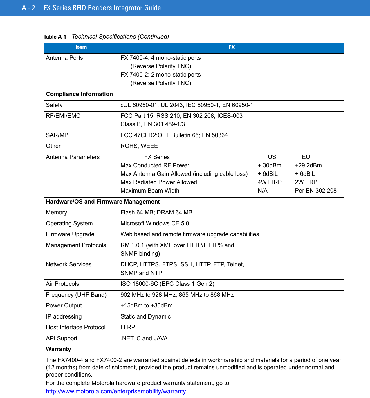
Zebra Technologies FX7400 FX Series RFID Reader User Manual
Zebra Technologies Corporation FX Series RFID Reader
UserManual.wiki
>
Zebra Technologies
>
FX7400 User Manual
>
User Manual 2
Contents
1.
User Manual 1
2.
User Manual 2
User Manual 2
Navigation menu
Upload a User Manual
Namespaces
Wiki Guide
HTML
PDF
Info
Views
User Manual
Discussion / Help
Navigation


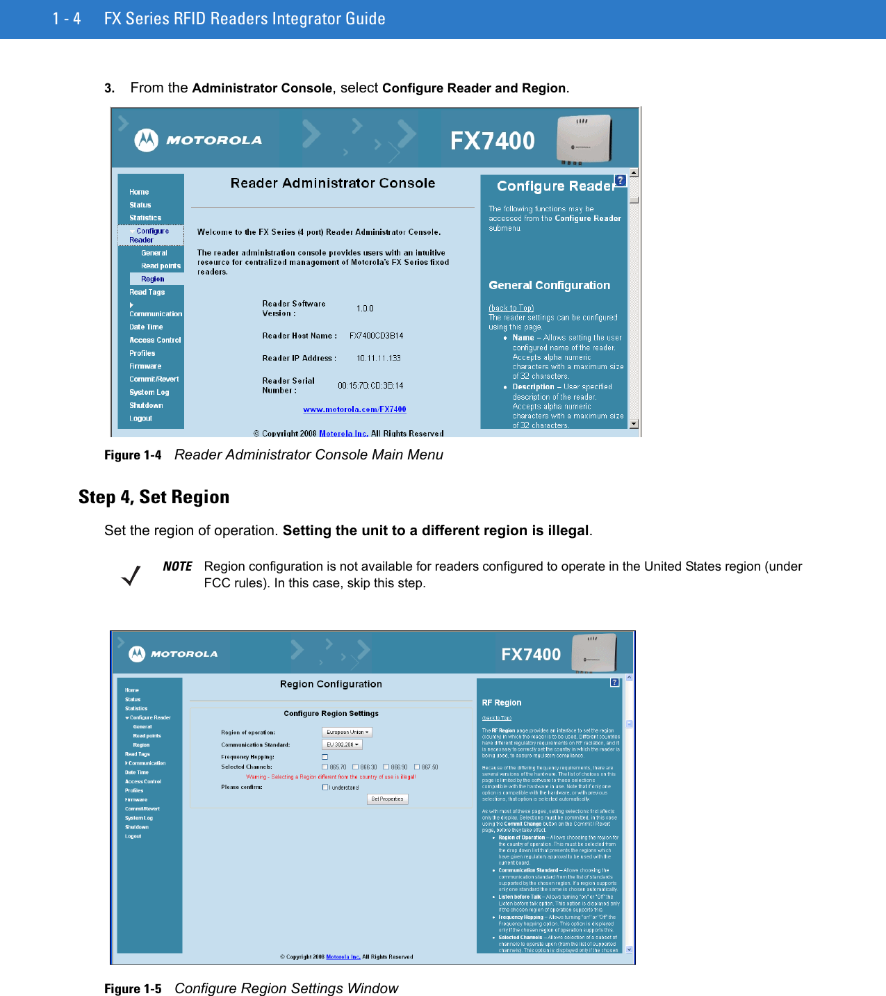

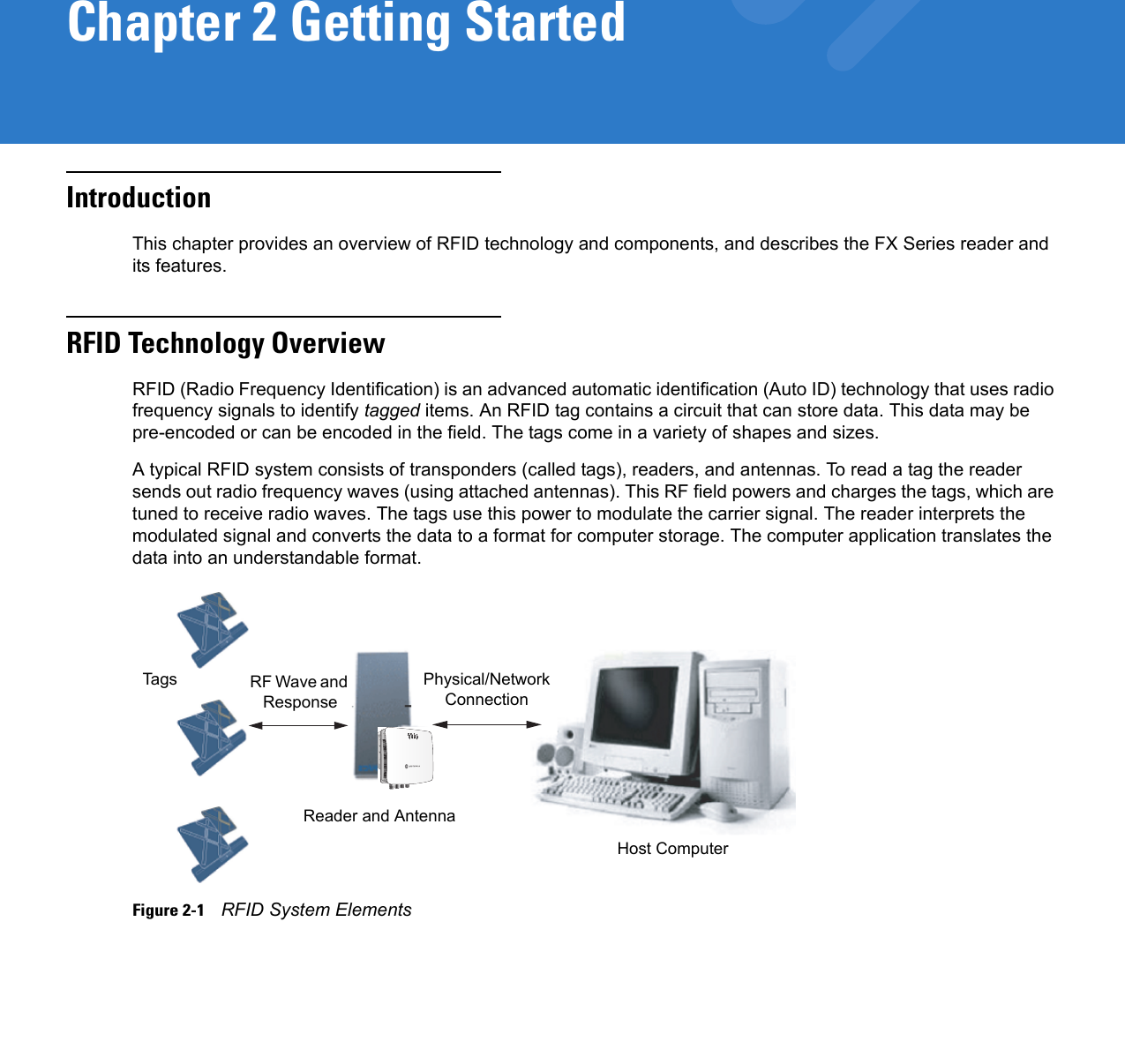
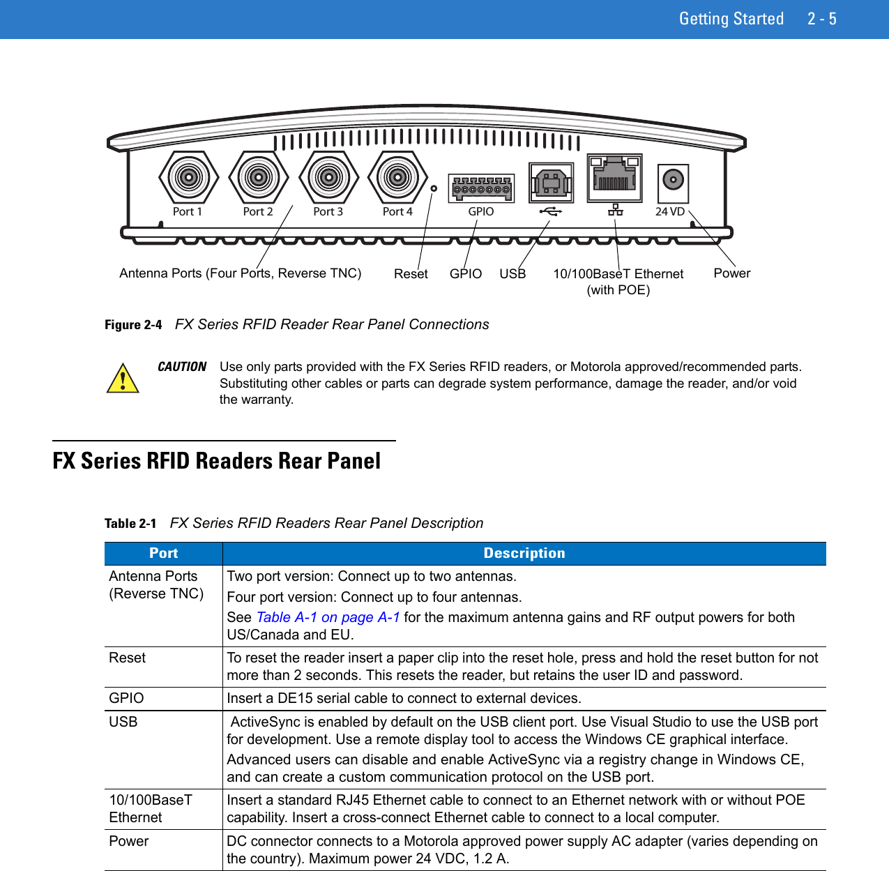
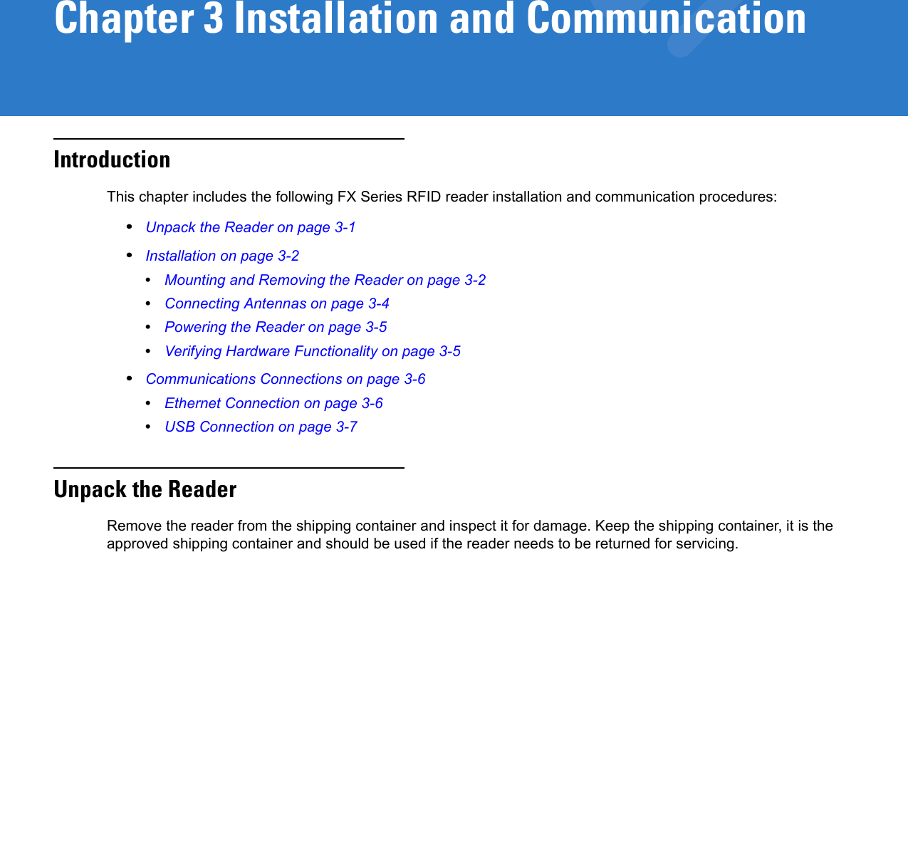


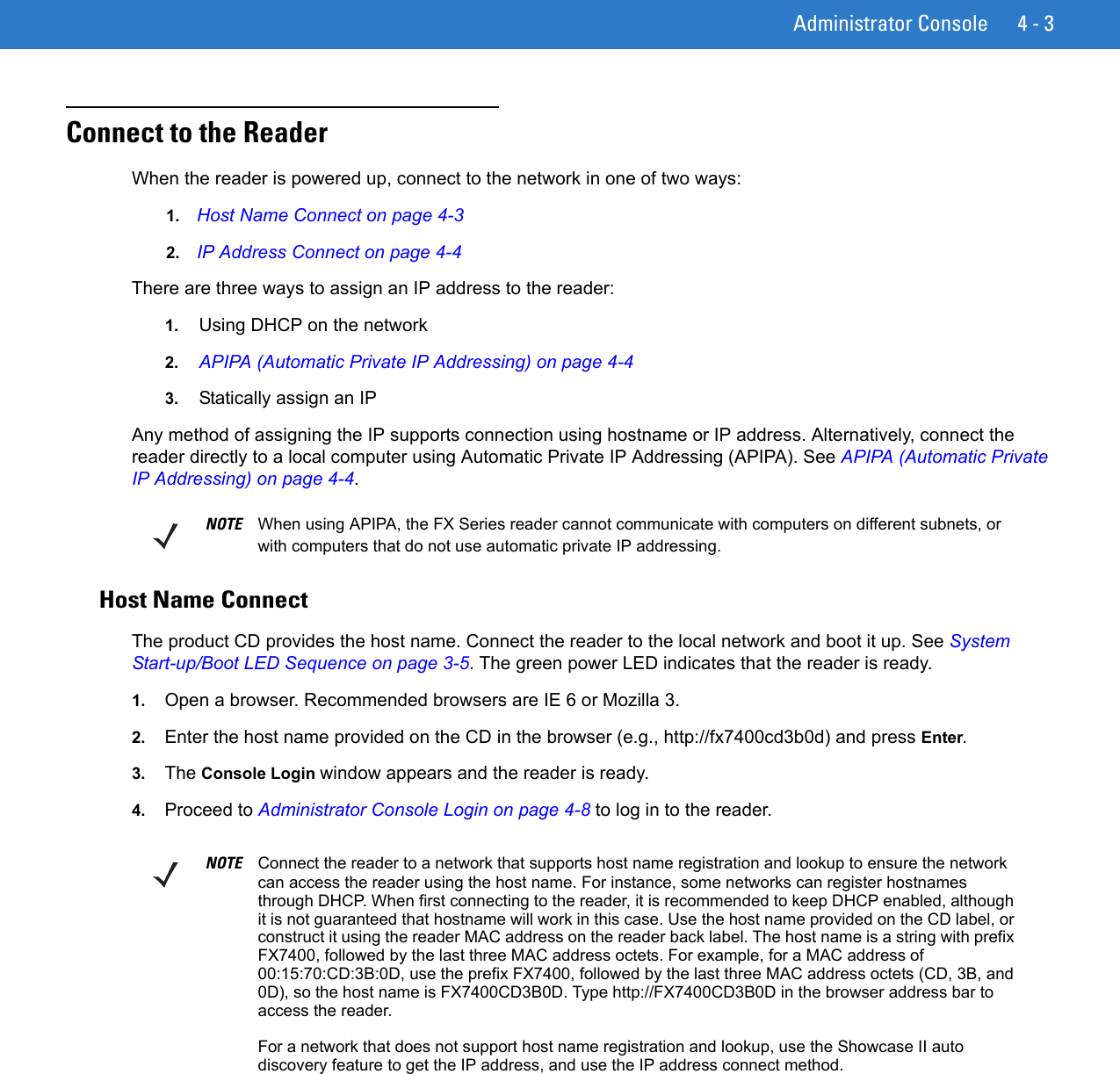

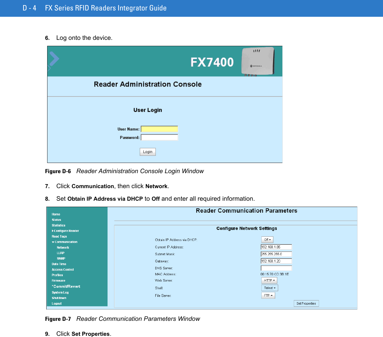
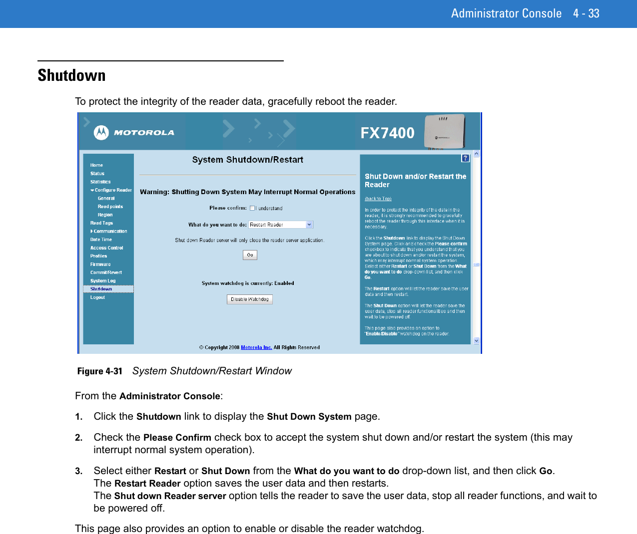
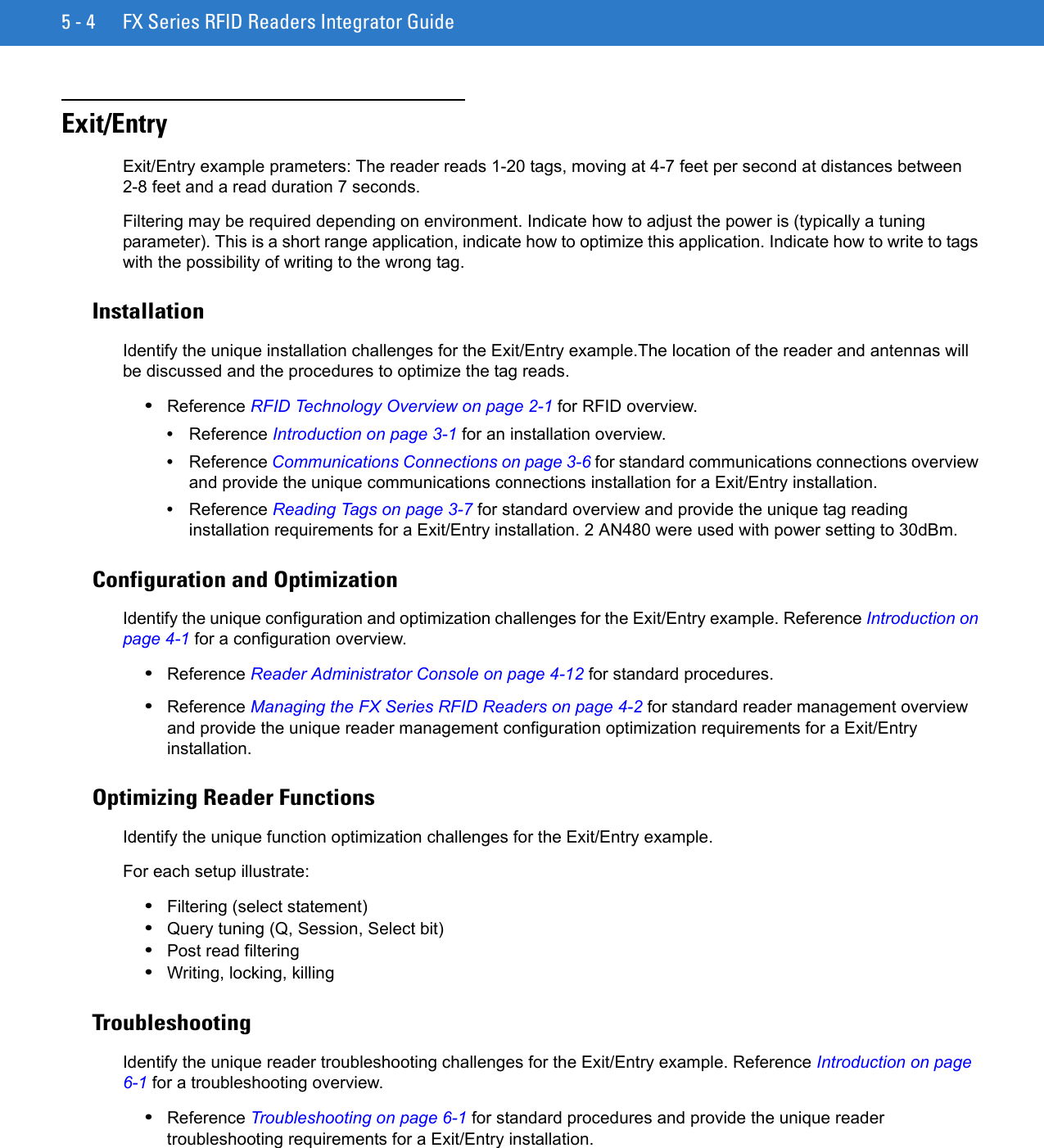
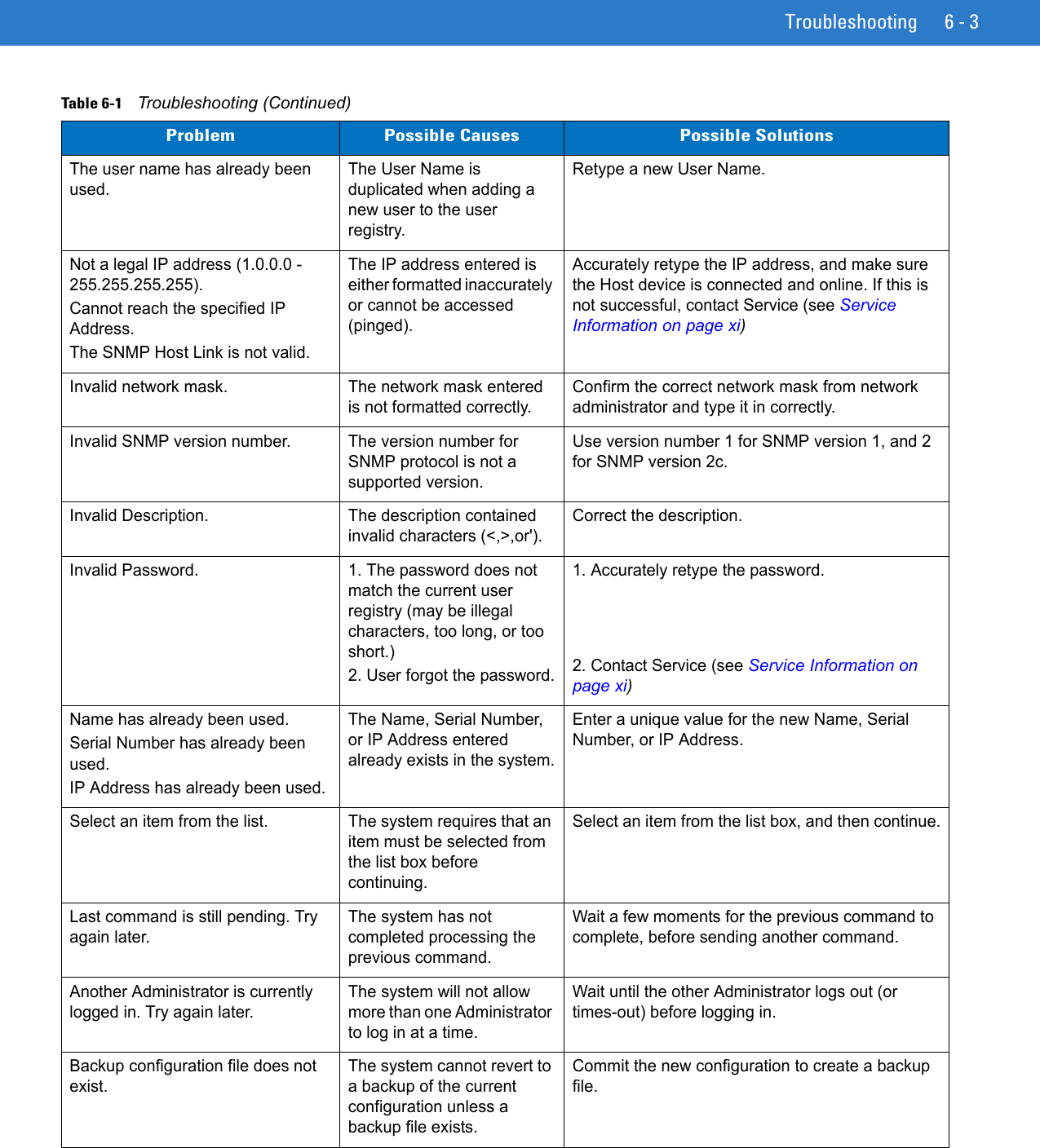
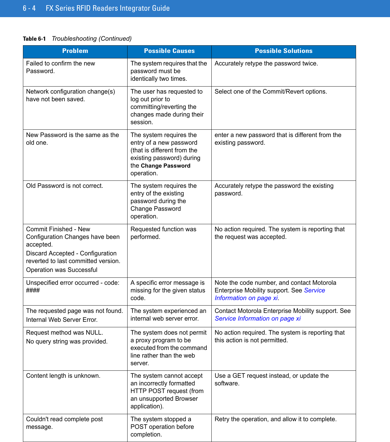
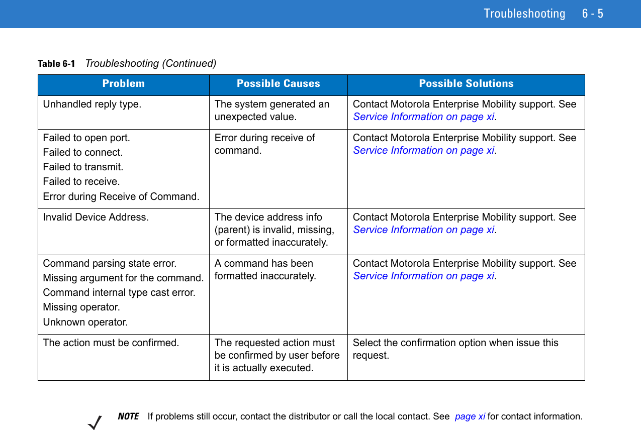
![Administrator Console 4 - 13•Firmware - see Firmware Version/Update on page 4-28•Commit/Revert - see Commit/Revert on page 4-31•System Log - see System Log on page 4-32•Shutdown - see Shutdown on page 4-33•Logout - click Logout to immediately log out of the Administrator ConsoleStatusClick Status on the console main menu to view the Reader Status window. This window displays information about the reader and read points (antennas). Figure 4-15 Reader Status WindowThe Reader Status window provides consolidated reader status information:•System Clock - The current system clock value, in the format [Year] [Month] [Day] [Hour: Minute: Second] [Time Difference with UTC]. Click the link to adjust the reader date and time settings.•Up Time - Displays how long the reader has been running, in the format of [Number of Days] [Number of Hours] [Number of Minutes] [Number of Seconds]. •CPU Usage - Displays the CPU usage, the user applications (if any), and the system usage. •RAM Usage - Displays the total allocated RAM for the reader, the memory used, and free memory. •Flash Usage - Displays the flash memory usage by partition. •Refresh Interval - Sets the refresh interval (in seconds) for the page. The status information refreshes every N seconds (where N is the user configured value for the refresh interval). The minimum refresh interval value is 10 seconds.](https://usermanual.wiki/Zebra-Technologies/FX7400.User-Manual-2/User-Guide-1202295-Page-51.png)
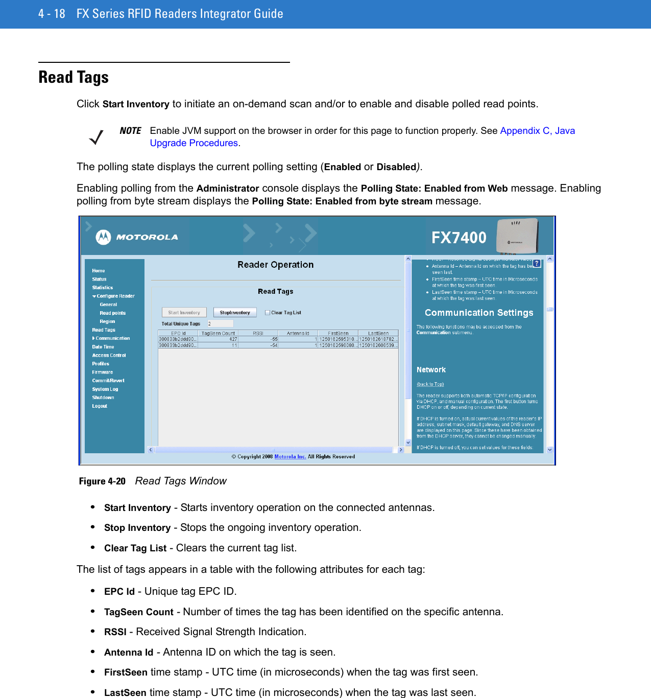

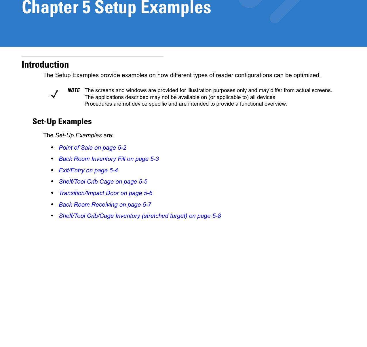
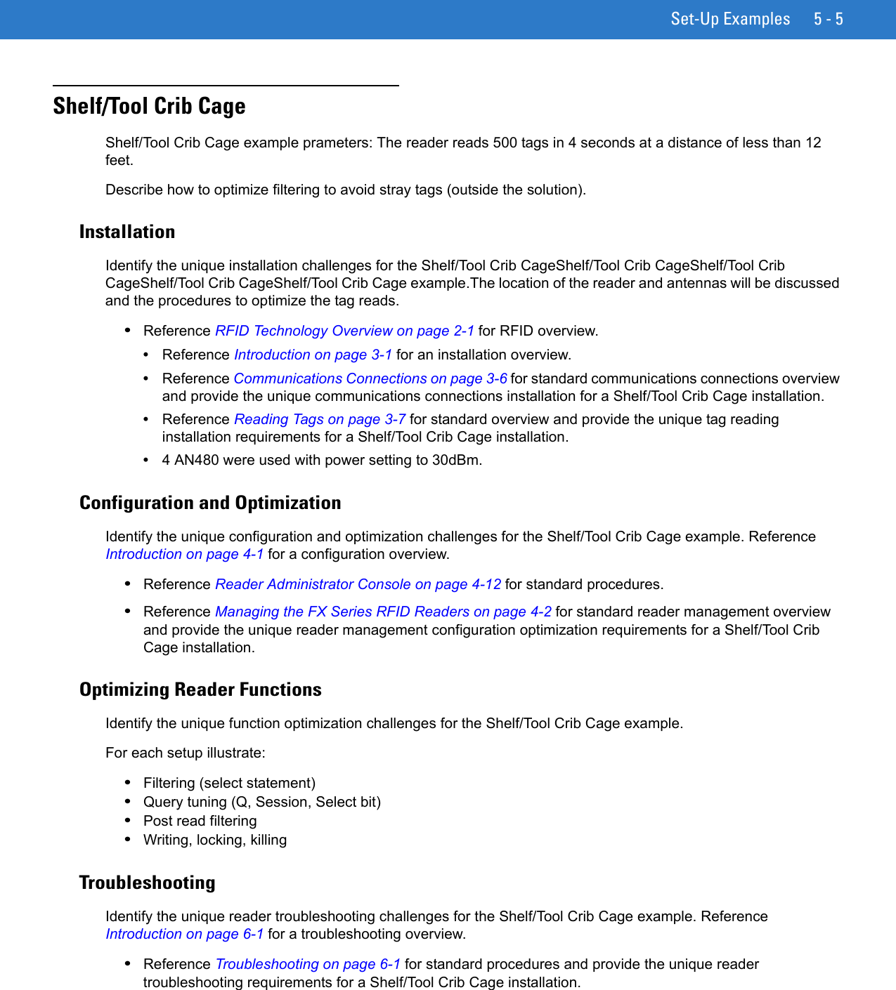


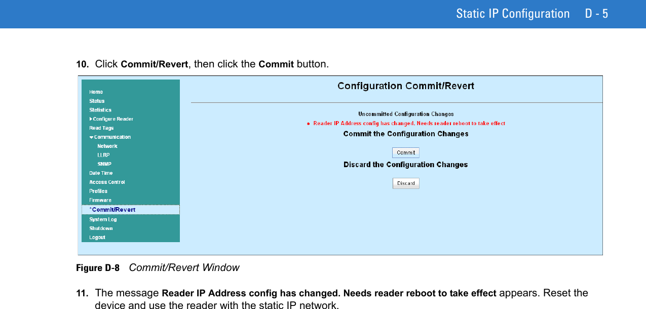
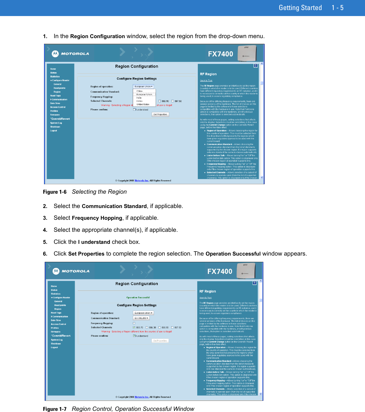
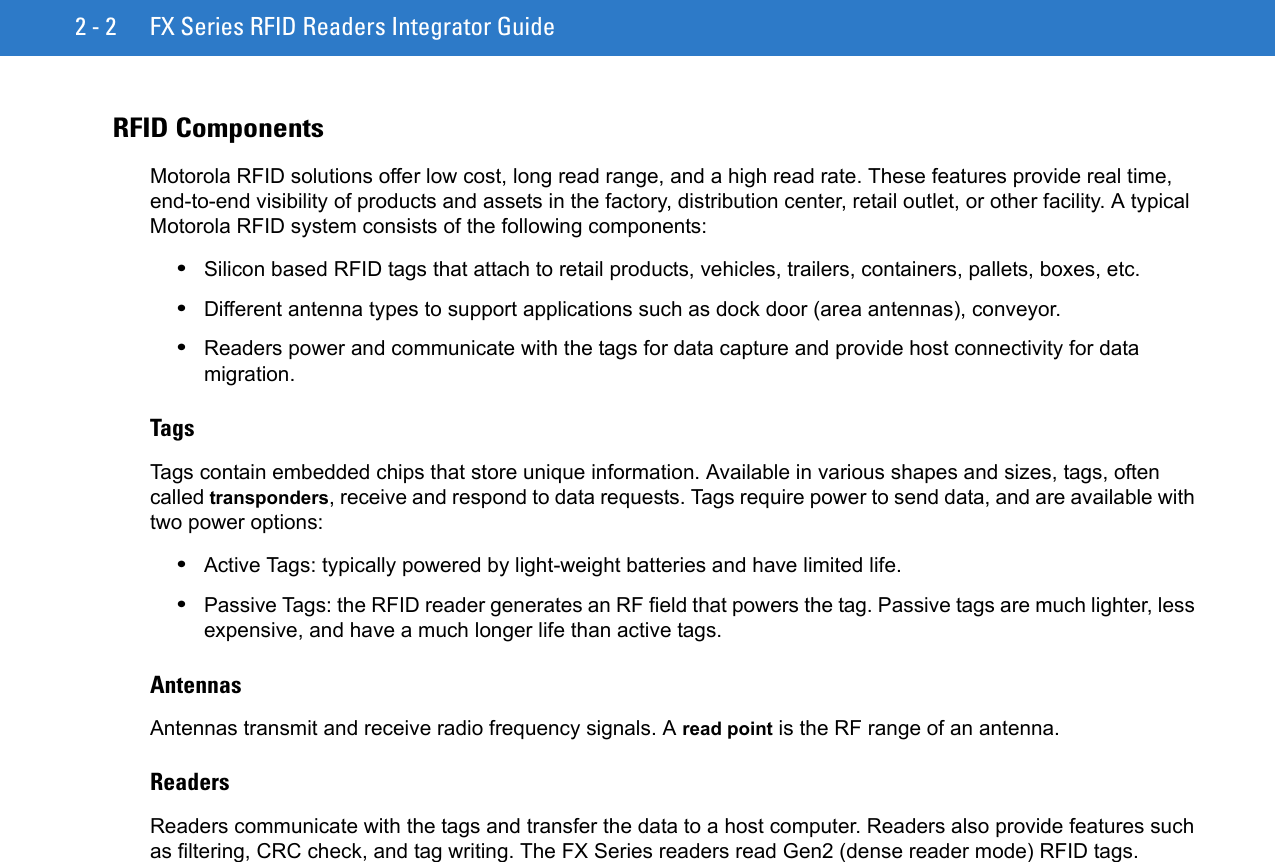
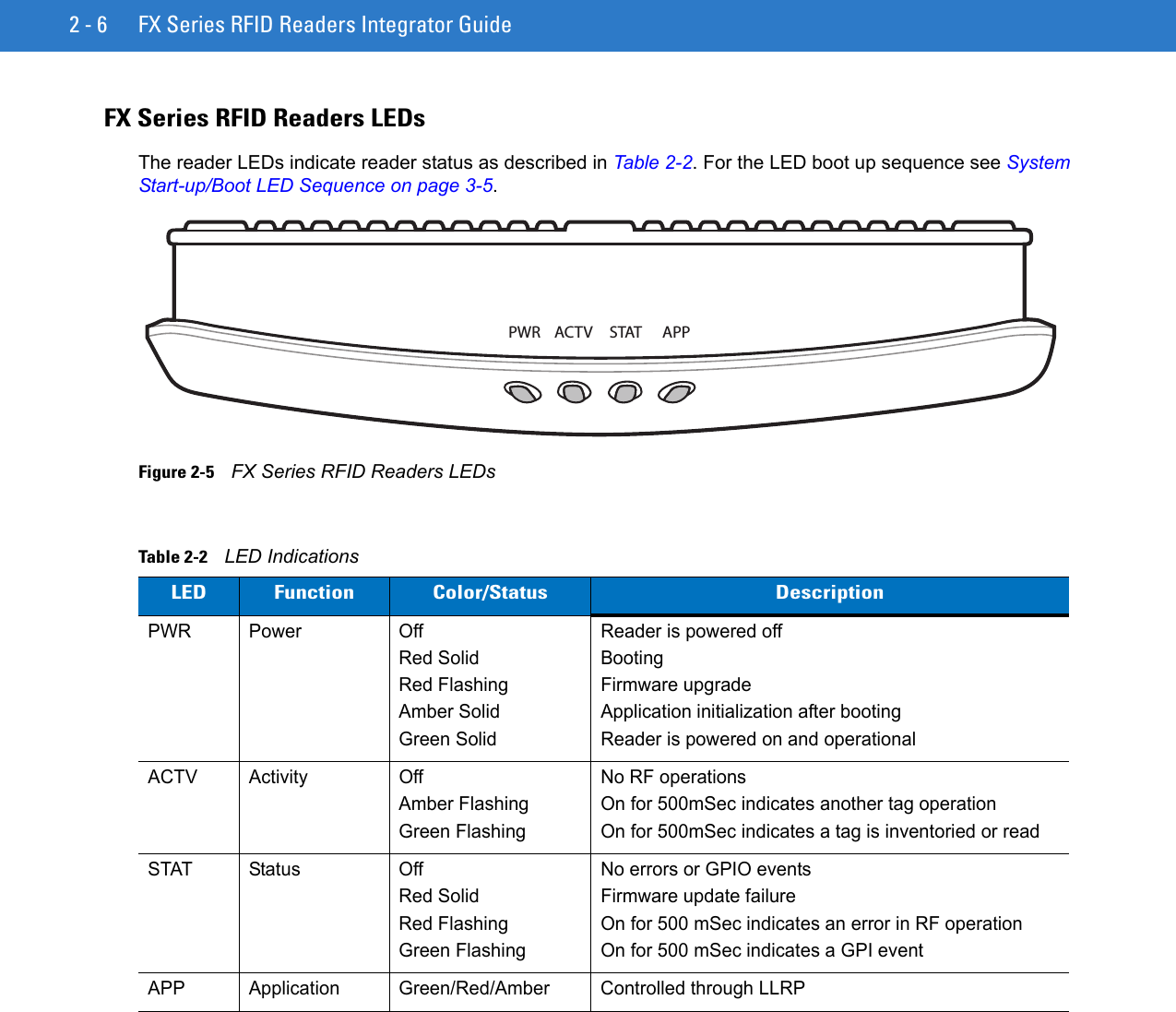
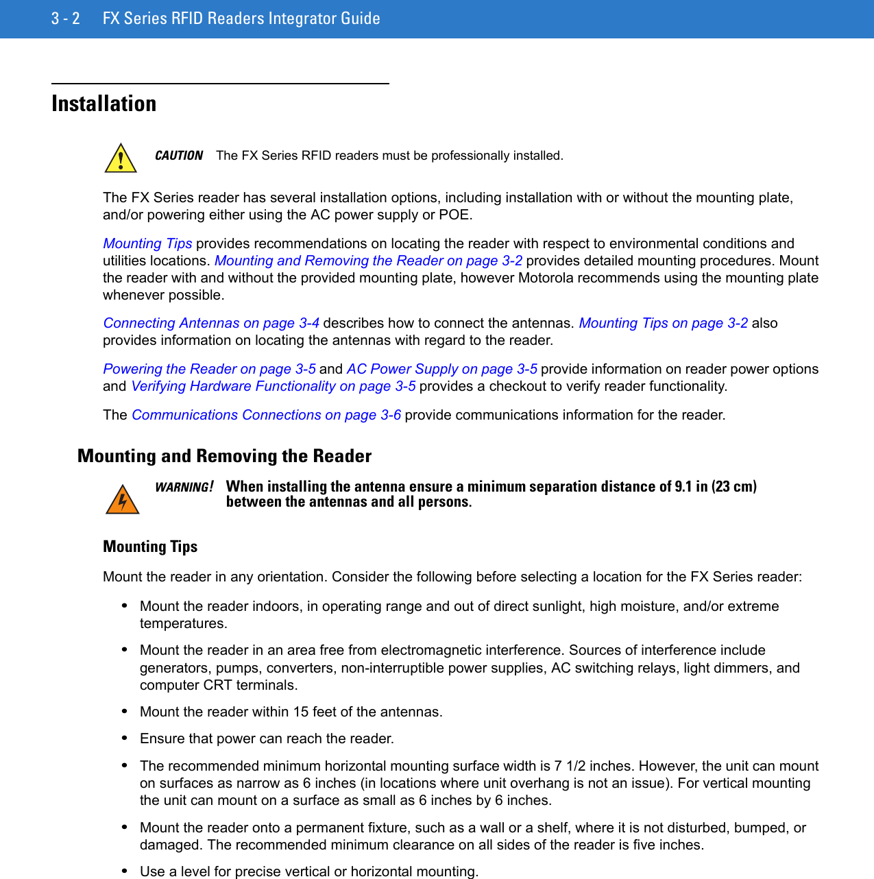
![Firmware Upgrade Procedures B - 3The -t parameter is the file type, -f is the name of the file, and -s the size. Ensure the file size is correct. ";" comments out the rest of the line.Update Method 1, Use a LANThis is the preferred method, since readers are typically on a LAN and the update does not require existing connections to change. 1. Create a folder on a local ftp server and name it: \FXUPDT\ReleaseXXX. 2. Download the firmware files from http://www.support.symbol.com into this folder and unzip the files if they are zipped.3. Ensure that the readers can be pinged from the host computer. If they cannot, consult with the network administrator. 4. On the reader to update, access the web based Administrator Console:a. Open a browser and type the IP address of the reader to update (format example: http://157.235.88.147). The Reader Administrator Console login screen appears. See Connect to the Reader on page 4-3.b. Enter the user name and password. If this is the first time accessing the console, a prompt appears for a user name and password update. The default settings are: Username: adminPassword: changeThe Administrator Console Main Menu appears. See Figure 4-14 on page 4-12. 5. From the Console Main Menu select Scan Control the Reader Scan Control.6. Click the Enable/Disable Polling button to set Disable Polling. The button reads Enable Polling when polling is disabled.7. Select Maintenance. The Reader Maintenance Console appears. See Figure 4-1 on page 4-2. [refers to Maintenance chapter that was removed; remove step??]8. Select Version. The Version Control screen appears with the current version information. See Figure 4-14 on page 4-22. [refers to Maintenance chapter that was removed; remove step??]9. To upgrade the firmware:a. Ensure the ftp server is running on the host computer. b. Ensure the TFTP server is running on the host computer, and that the file path is the same as when logging on using the FTP server.c. On the Version Control screen, enter in the following information:For the ftp Server link, enter ftp://<ip address of host computer>/filepath (format example: ftp://192.168.1.3// FX UPDT/ReleaseXXX). Be sure to enter an IP address; entering the host name does not work.Enter the ftp server user name. Enter the ftp server password. NOTE If using the default host computer ftp server, the system user name and password may be required (consult the system administrator).](https://usermanual.wiki/Zebra-Technologies/FX7400.User-Manual-2/User-Guide-1202295-Page-97.png)
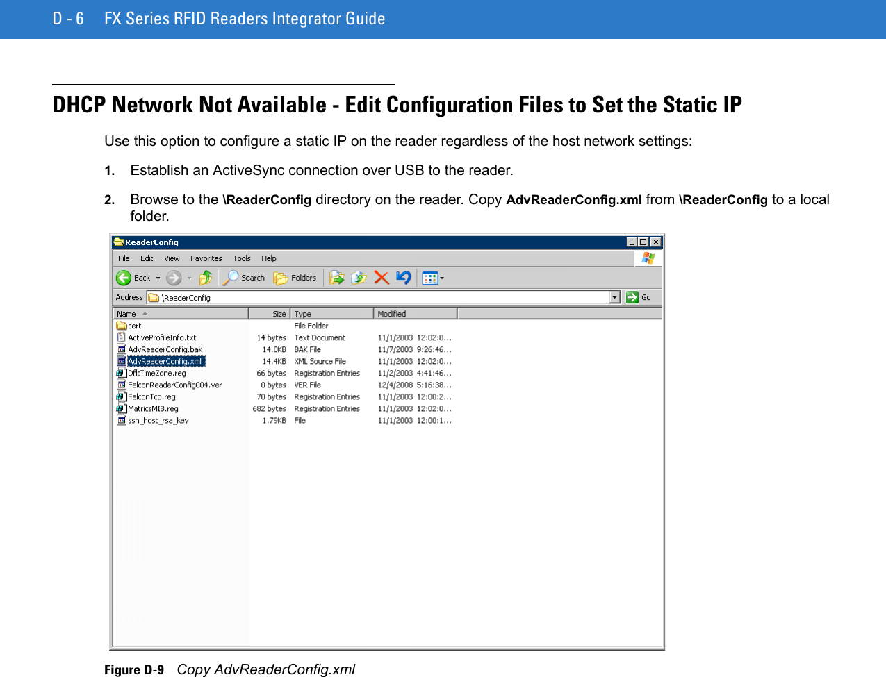
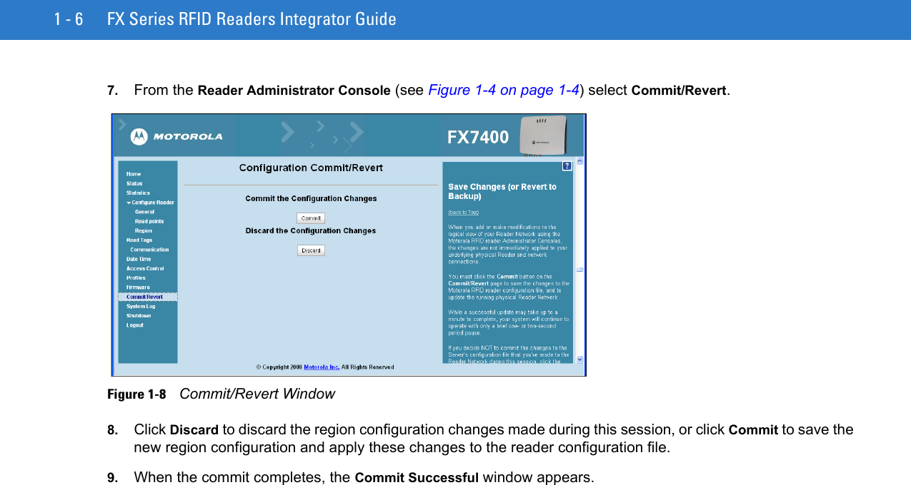
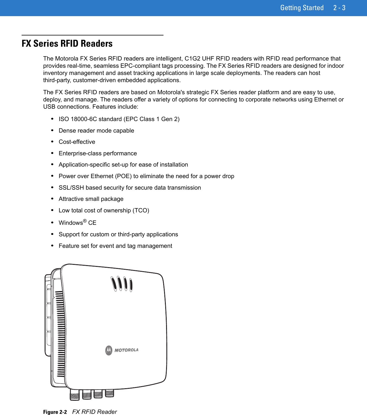
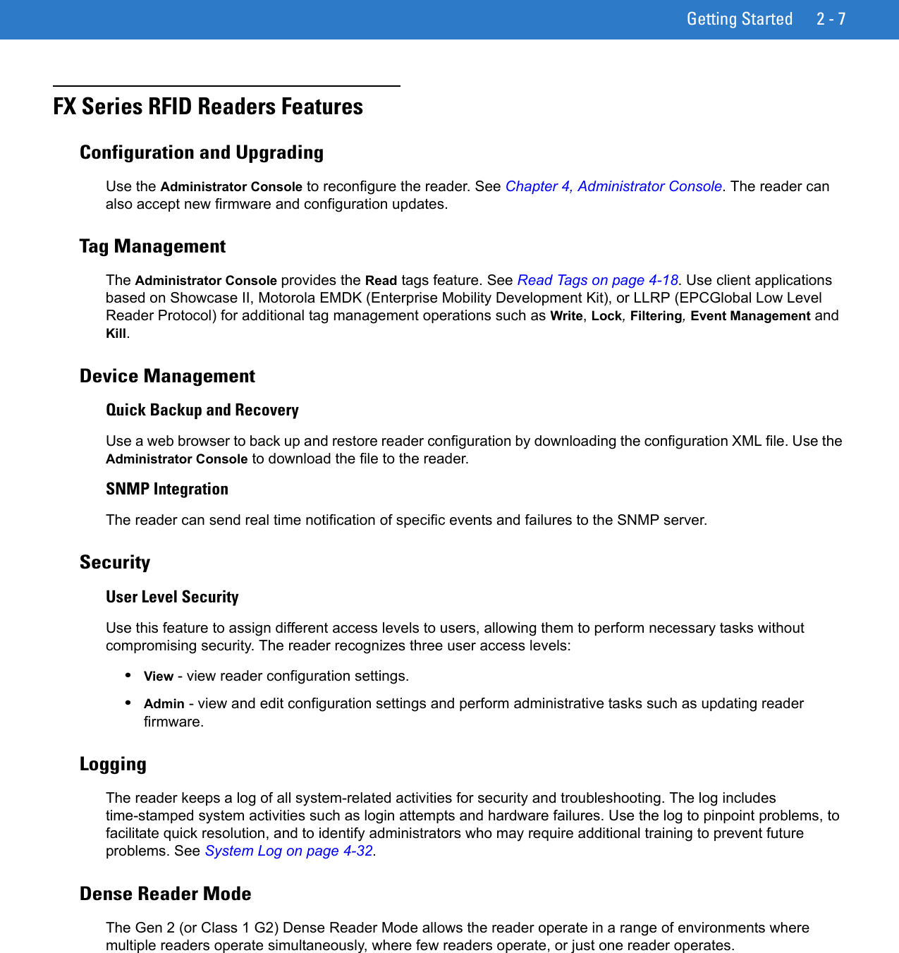
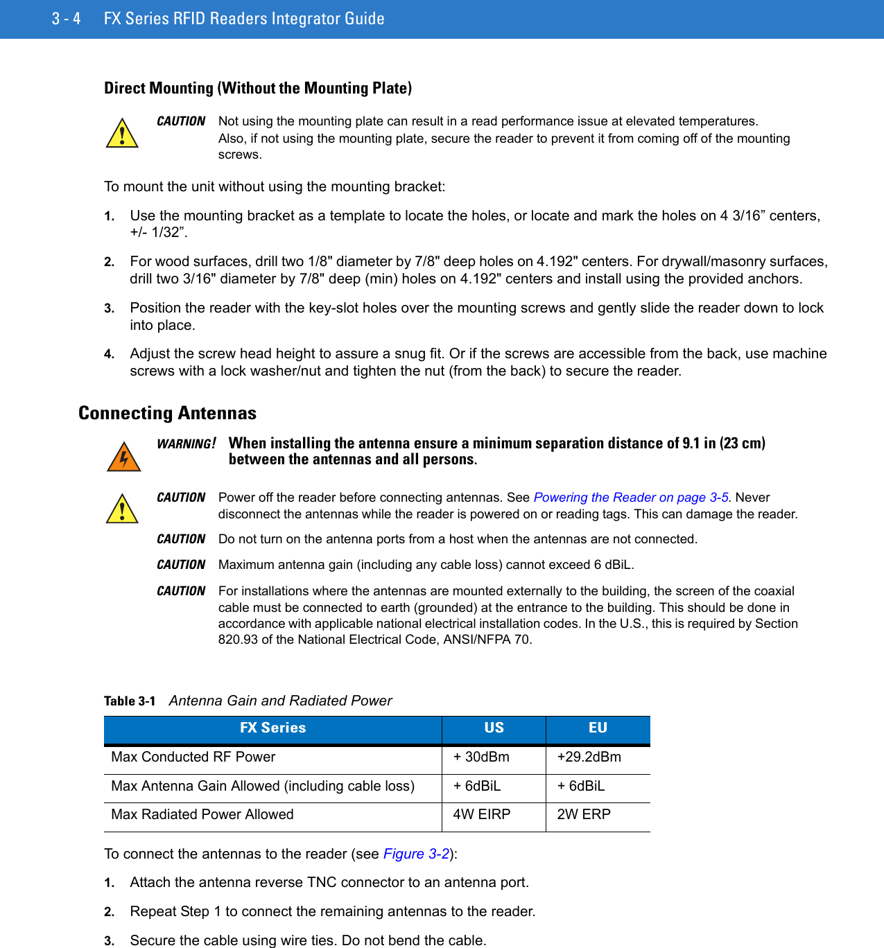
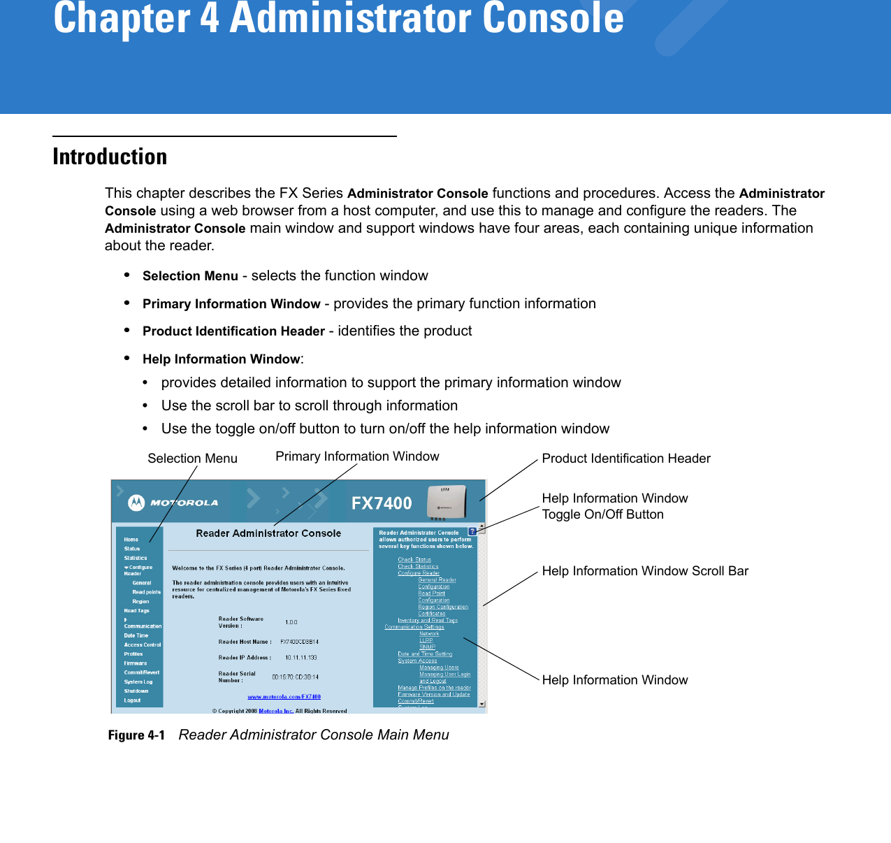
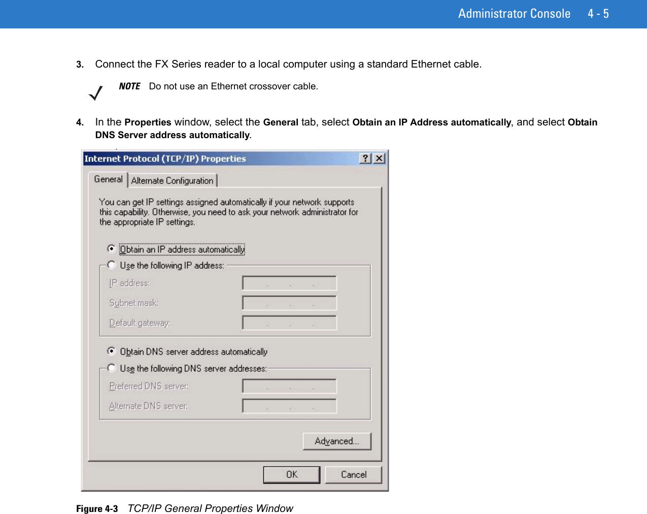
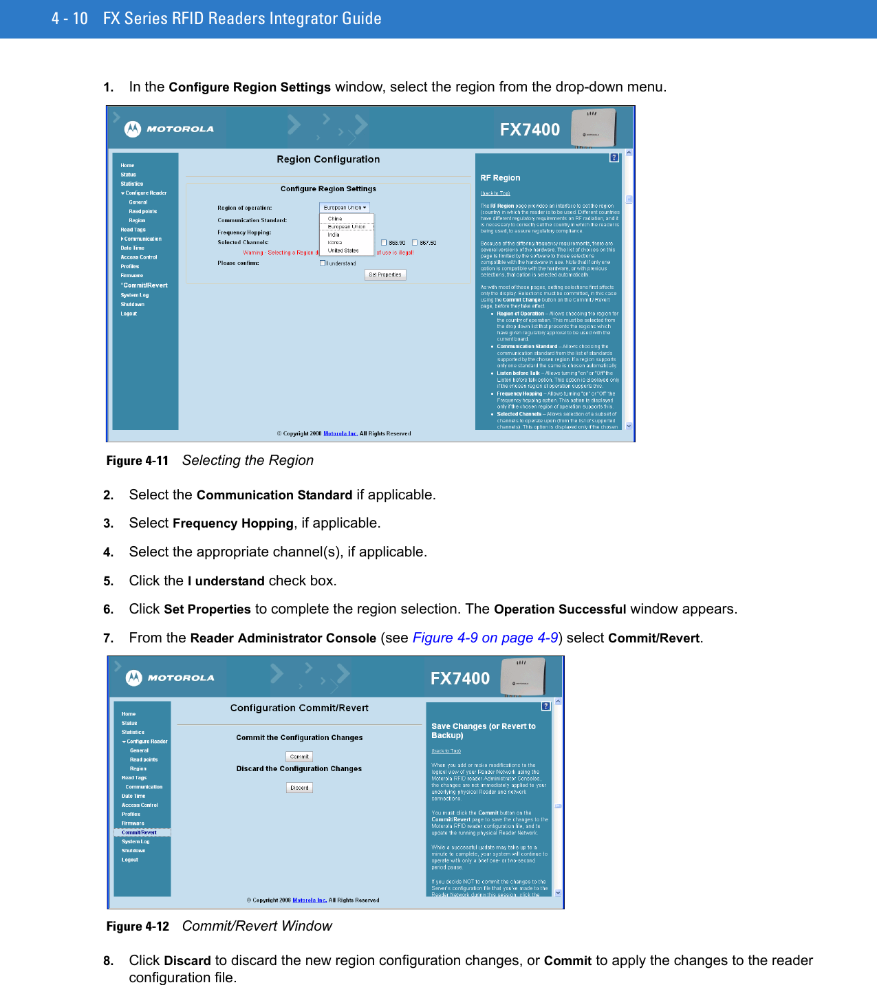
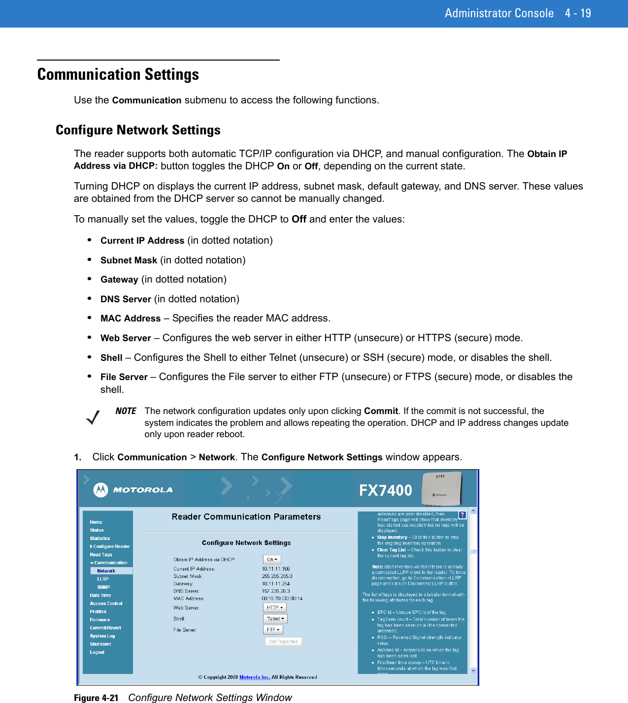
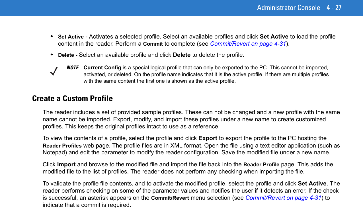
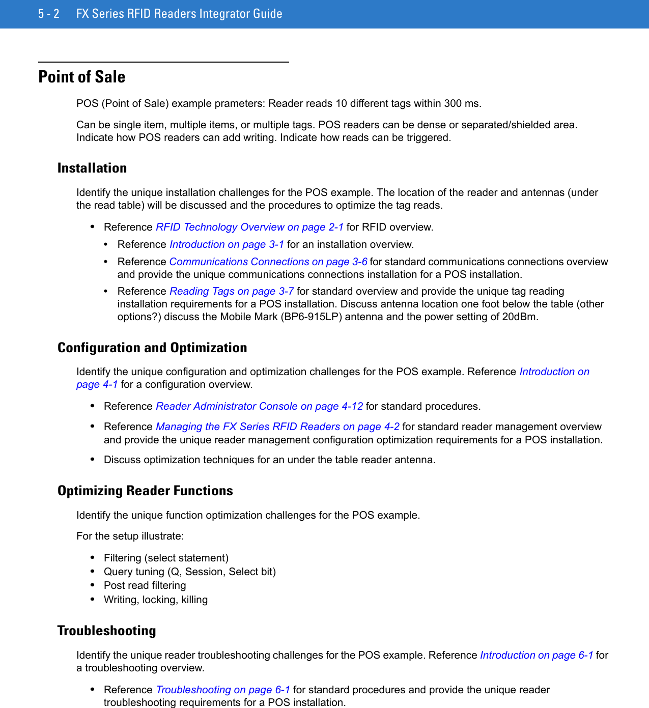
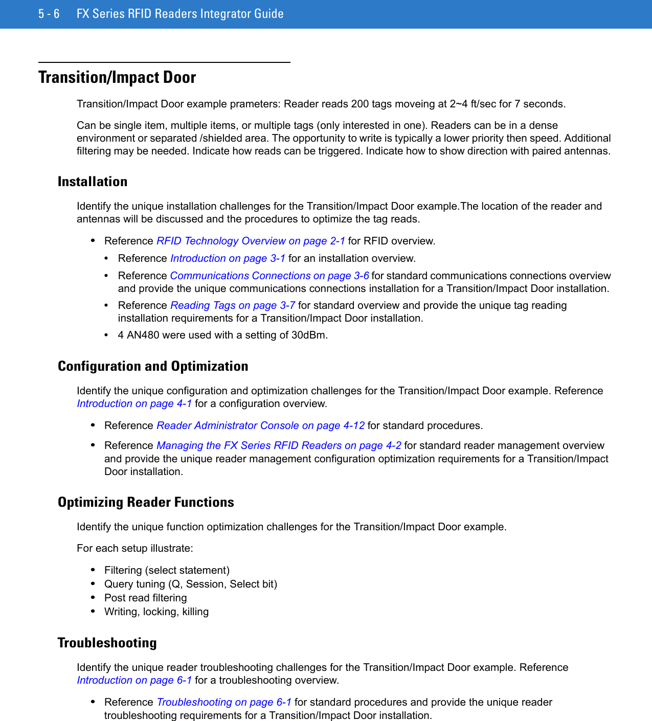
![Firmware Upgrade Procedures B - 5Update Method 2, Direct Connect Over the Ethernet PortUse this method to update a reader that is not on a LAN. 1. Use the serial Administrator Console to disable DHCP on the reader, and configure it for a static IP address (192.168.1.3).2. Configure the host computer to reside on the same subnet as the reader:a. Open Network Connections and locate the connection to use to connect to the reader.b. Open the TCP/IP Connection Properties window. Modify this to use a static IP address on the same subnet as the reader (192.168.1.5). Click OK.Figure B-1 TCP/IP Connection Properties Screen3. Connect the Cat5 crossover cable from the host computer to the reader.4. On the reader, access the web-based Administrator Console:a. Open a browser and type http://192.168.1.3 (or the IP address of the reader to upgrade, if it is not the default address above). The Reader Administrator Console login screen appears. See Connect to the Reader on page 4-3.b. Enter the user name and password. If this is the first time accessing the console, a prompt appears for a user name and password update. The default settings are: Username: adminPassword: changeThe Console Main Menu appears. See Figure 4-14 on page 4-12. 5. From the Console Main Menu select Scan Control. The Reader Scan Control screen appears.6. Click the Enable/Disable Polling button to set to Disable Polling. The button reads Enable Polling if polling is disabled.7. Select Maintenance. The Reader Maintenance Console appears. See Figure 4-1 on page 4-2. [refers to Maintenance chapter that was removed; remove step??]8. Select Version. The Version Control window displays the current version information. See Figure 4-14 on page 4-22. [refers to Maintenance chapter that was removed; remove step??]](https://usermanual.wiki/Zebra-Technologies/FX7400.User-Manual-2/User-Guide-1202295-Page-99.png)
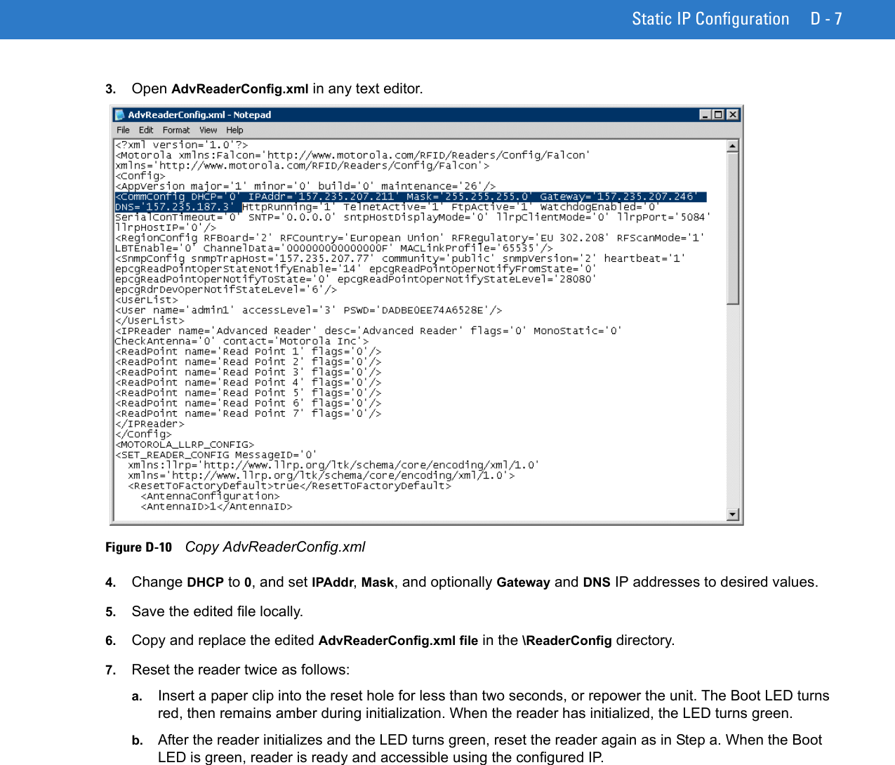
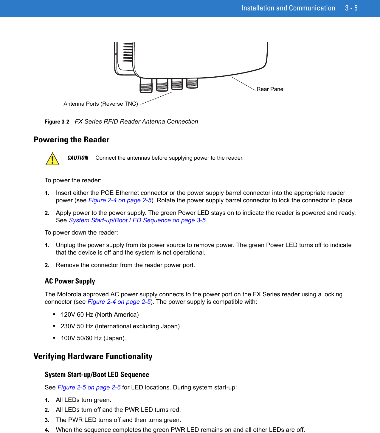
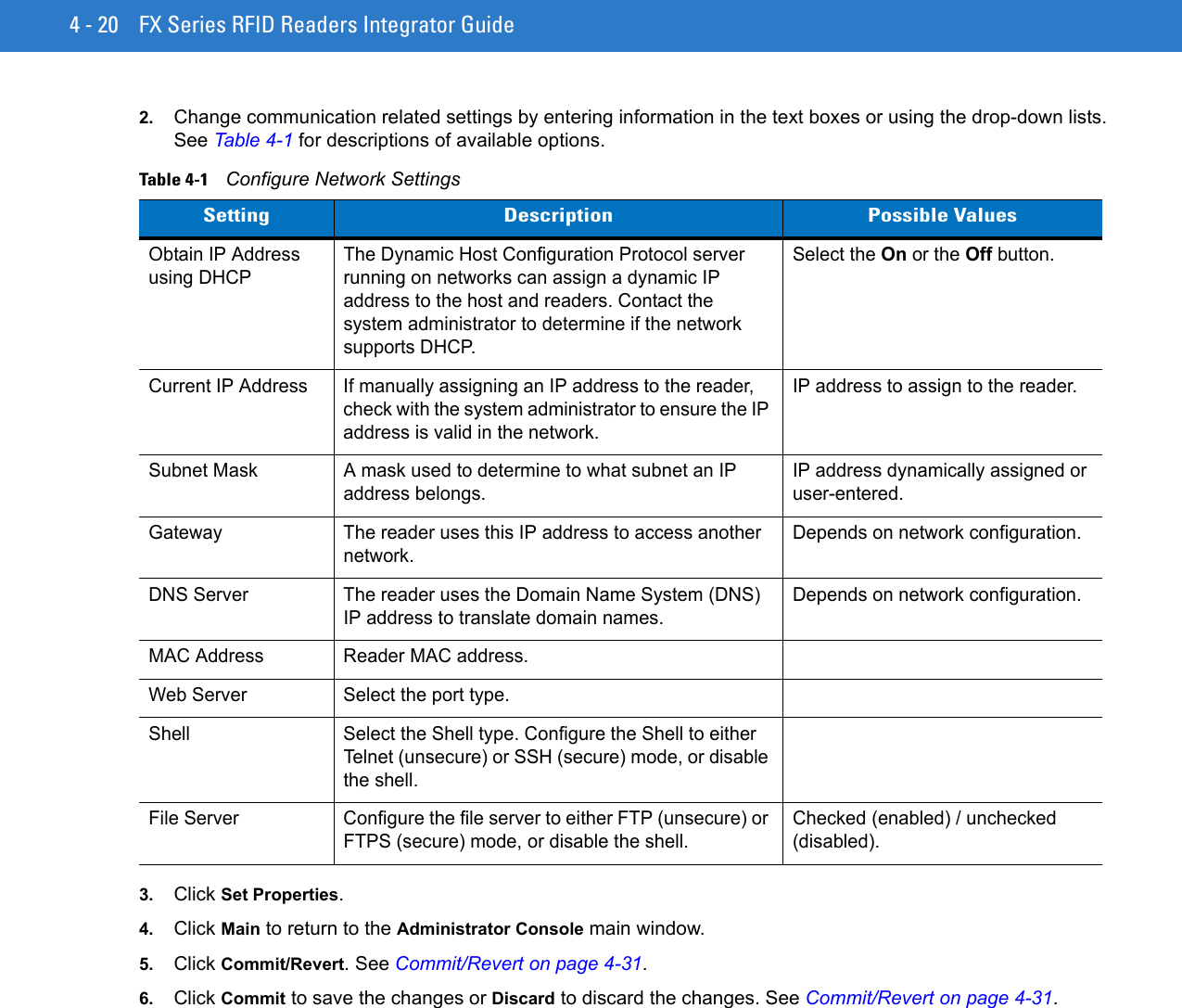
![B - 6 FX Series RFID Readers Integrator Guide9. Upgrade the firmware:a. Ensure that an ftp server is running on the host computer. Do not change any other default setting (the necessary defaults should already be in C:/FXUPDT/ReleaseXXX).b. On the Version Control screen, enter in the following information:For the ftp Server link, enter ftp://<ip address of host computer>/filepath (ftp://192.168.1.5// FXUPDT/ ReleaseXXX). Be sure to enter an IP address; entering the host name does not work.Enter the ftp server user name. Enter the ftp server password. c. Click Start Update. See Figure 4-14 on page 4-22. The reader indicates that it is shutting down. [refers to Maintenance chapter that was removed; remove step??]d. The green LED on the reader flashes during the update. The reader application software first downloads osupFX.exe, FlashUpdateUtility.dll, and Response.txt files, starts running Osupdate, and shuts down. Osupdate then downloads all files specified in the Response.txt file into RAM, and if successful writes the files to Flash. If the ftp is not successful, no files are written to Flash. e. This update can take up to 15 minutes. Do not remove power to the reader or reboot the reader during the update.f. The reader reboots when the update completes.10. Log onto the web console and access the Version Control window. Verify the new upgrade version is running.NOTE Refer to the release notes to determine which files changed; Not all of the files are updated in every release. There is no specific order necessary when installing these files.NOTE If using the default host computer ftp server, the system user name and password may be required (consult the System Administrator).](https://usermanual.wiki/Zebra-Technologies/FX7400.User-Manual-2/User-Guide-1202295-Page-100.png)