Zebra Technologies FX7400 FX Series RFID Reader User Manual
Zebra Technologies Corporation FX Series RFID Reader
Contents
- 1. User Manual 1
- 2. User Manual 2
User Manual 2
FX Series RFID Readers
Integrator Guide

FX Series RFID Readers
Integrator Guide
72E-122490-01
Revision .2
August 2009

ii FX Series RFID readers Integrator Guide
© 2009 by Motorola, Inc. All rights reserved.
No part of this publication may be reproduced or used in any form, or by any electrical or mechanical means,
without permission in writing from Motorola. This includes electronic or mechanical means, such as
photocopying, recording, or information storage and retrieval systems. The material in this manual is subject to
change without notice.
The software is provided strictly on an “as is” basis. All software, including firmware, furnished to the user is on
a licensed basis. Motorola grants to the user a non-transferable and non-exclusive license to use each
software or firmware program delivered hereunder (licensed program). Except as noted below, such license
may not be assigned, sublicensed, or otherwise transferred by the user without prior written consent of
Motorola. No right to copy a licensed program in whole or in part is granted, except as permitted under
copyright law. The user shall not modify, merge, or incorporate any form or portion of a licensed program with
other program material, create a derivative work from a licensed program, or use a licensed program in a
network without written permission from Motorola. The user agrees to maintain Motorola’s copyright notice on
the licensed programs delivered hereunder, and to include the same on any authorized copies it makes, in
whole or in part. The user agrees not to decompile, disassemble, decode, or reverse engineer any licensed
program delivered to the user or any portion thereof.
Motorola reserves the right to make changes to any software or product to improve reliability, function, or
design.
Motorola does not assume any product liability arising out of, or in connection with, the application or use of
any product, circuit, or application described herein.
No license is granted, either expressly or by implication, estoppel, or otherwise under any Motorola, Inc.,
intellectual property rights. An implied license only exists for equipment, circuits, and subsystems contained in
Motorola products.
MOTOROLA and the Stylized M Logo and Symbol and the Symbol logo are registered in the US Patent &
Trademark Office. Bluetooth is a registered trademark of Bluetooth SIG. Microsoft, Windows and ActiveSync
are either registered trademarks or trademarks of Microsoft Corporation. All other product or service names
are the property of their respective owners.
Motorola, Inc.
One Motorola Plaza
Holtsville, New York 11742-1300
http://www.motorola.com/enterprisemobility
Patents
This product is covered by one or more of the patents listed on the website:
http://www.motorola.com/enterprisemobility/patents.
Warranty
For the complete Motorola hardware product warranty statement, go to:
http://www.motorola.com/enterprisemobility/warranty.

iii
Revision History
Changes to the original manual are listed below:
Change Date Description
-01 Rev .1 06/2009 Beta release
-01 Rev .2 08/2009 Reviewer updates

iv FX Series RFID readers Integrator Guide

Table of Contents
About This Guide
Introduction ........................................................................................................................................... ix
Configurations................................................................................................................................. ix
Chapter Descriptions ............................................................................................................................ x
Notational Conventions......................................................................................................................... x
Related Documents and Software........................................................................................................ xi
Service Information............................................................................................................................... xi
Chapter 1: Quick Start
Introduction .......................................................................................................................................... 1-1
Quick Start Demonstration ................................................................................................................... 1-1
Step 1, Setup ................................................................................................................................. 1-1
Step 2, Host Name Connect .......................................................................................................... 1-2
Step 3, First Time / Start-Up Login ................................................................................................ 1-3
Step 4, Set Region ......................................................................................................................... 1-4
Step 5, Read Tags ......................................................................................................................... 1-7
Chapter 2: Getting Started
Introduction .......................................................................................................................................... 2-1
RFID Technology Overview ................................................................................................................. 2-1
RFID Components ......................................................................................................................... 2-2
FX Series RFID Readers ..................................................................................................................... 2-3
Versions and Kits ........................................................................................................................... 2-4
FX Series RFID Reader ....................................................................................................................... 2-4
FX Series RFID Readers Rear Panel .................................................................................................. 2-5
FX Series RFID Readers LEDs ..................................................................................................... 2-6
FX Series RFID Readers Features ...................................................................................................... 2-7
Configuration and Upgrading ......................................................................................................... 2-7
Tag Management ........................................................................................................................... 2-7
Device Management ...................................................................................................................... 2-7
Security .......................................................................................................................................... 2-7
Logging .......................................................................................................................................... 2-7

vi FX Series RFID Readers Integrator Guide
Dense Reader Mode ...................................................................................................................... 2-7
Connection Options ....................................................................................................................... 2-8
Chapter 3: Installation and Communication
Introduction .......................................................................................................................................... 3-1
Unpack the Reader .............................................................................................................................. 3-1
Installation ............................................................................................................................................ 3-2
Mounting and Removing the Reader ............................................................................................. 3-2
Connecting Antennas ..................................................................................................................... 3-4
Powering the Reader ..................................................................................................................... 3-5
Verifying Hardware Functionality ................................................................................................... 3-5
Communications Connections ............................................................................................................. 3-6
Ethernet Connection ...................................................................................................................... 3-6
USB Connection ............................................................................................................................ 3-7
Reading Tags ...................................................................................................................................... 3-7
Chapter 4: Administrator Console
Introduction .......................................................................................................................................... 4-1
Managing the FX Series RFID Readers .............................................................................................. 4-2
Profiles ........................................................................................................................................... 4-2
Reset Reader ................................................................................................................................. 4-2
Connect to the Reader ......................................................................................................................... 4-3
Host Name Connect ....................................................................................................................... 4-3
IP Address Connect ....................................................................................................................... 4-4
APIPA (Automatic Private IP Addressing) ..................................................................................... 4-4
IP Address ..................................................................................................................................... 4-7
Administrator Console Login ................................................................................................................ 4-8
First Time / Start-Up Login ............................................................................................................. 4-8
Normal Login .................................................................................................................................. 4-11
Reader Administrator Console ............................................................................................................. 4-12
Administrator Console Option Selections ...................................................................................... 4-12
Status ................................................................................................................................................... 4-13
Configure Reader ................................................................................................................................ 4-14
Reader Parameters ........................................................................................................................ 4-14
Configure Read Point ..................................................................................................................... 4-15
Configure RF Region ..................................................................................................................... 4-16
Reader Statistics .................................................................................................................................. 4-17
Read Tags ........................................................................................................................................... 4-18
Communication Settings ...................................................................................................................... 4-19
Configure Network Settings ........................................................................................................... 4-19
LLRP Communications Protocol .................................................................................................... 4-21
SNMP Settings ............................................................................................................................... 4-23
System Time Management .................................................................................................................. 4-24
Access Control ..................................................................................................................................... 4-25
Manage Users ................................................................................................................................ 4-25
Reader Profiles .................................................................................................................................... 4-26
Create a Custom Profile ................................................................................................................. 4-27
Firmware Version/Update .................................................................................................................... 4-28

Table of Contents vii
FTP / FTPS Server ........................................................................................................................ 4-28
File Upload ..................................................................................................................................... 4-30
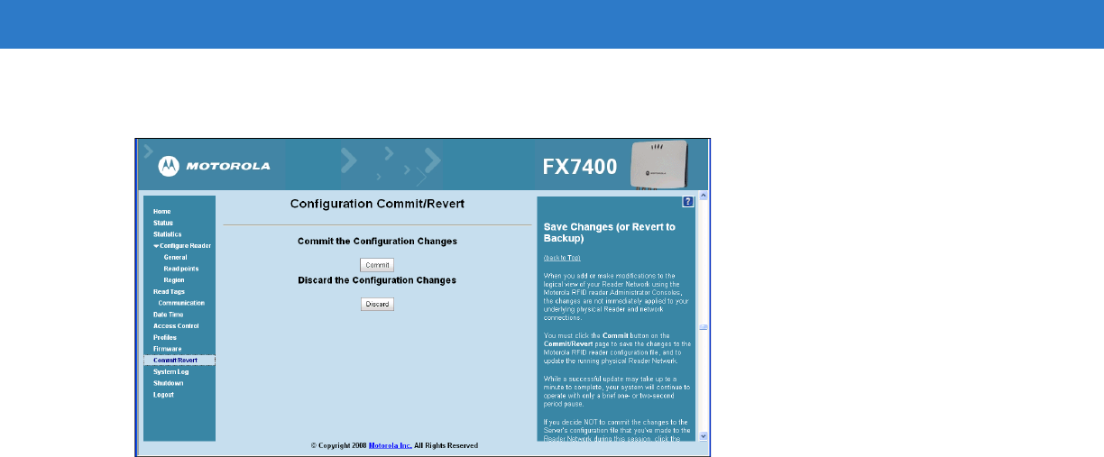
Commit/Revert ..................................................................................................................................... 4-31
System Log .......................................................................................................................................... 4-32
Shutdown ............................................................................................................................................. 4-33
Chapter 5: Setup Examples
Introduction .......................................................................................................................................... 5-1
Set-Up Examples ........................................................................................................................... 5-1
Point of Sale ........................................................................................................................................ 5-2
Installation ...................................................................................................................................... 5-2
Configuration and Optimization ...................................................................................................... 5-2
Optimizing Reader Functions ......................................................................................................... 5-2
Troubleshooting ............................................................................................................................. 5-2
Back Room Inventory Fill ..................................................................................................................... 5-3
Installation ...................................................................................................................................... 5-3
Configuration and Optimization ...................................................................................................... 5-3
Optimizing Reader Functions ......................................................................................................... 5-3
Troubleshooting ............................................................................................................................. 5-3
Exit/Entry ............................................................................................................................................. 5-4
Installation ...................................................................................................................................... 5-4
Configuration and Optimization ...................................................................................................... 5-4
Optimizing Reader Functions ......................................................................................................... 5-4
Troubleshooting ............................................................................................................................. 5-4
Shelf/Tool Crib Cage ........................................................................................................................... 5-5
Installation ...................................................................................................................................... 5-5
Configuration and Optimization ...................................................................................................... 5-5
Optimizing Reader Functions ......................................................................................................... 5-5
Troubleshooting ............................................................................................................................. 5-5
Transition/Impact Door ........................................................................................................................ 5-6
Installation ...................................................................................................................................... 5-6
Configuration and Optimization ...................................................................................................... 5-6
Optimizing Reader Functions ......................................................................................................... 5-6
Troubleshooting ............................................................................................................................. 5-6
Back Room Receiving ......................................................................................................................... 5-7
Installation ...................................................................................................................................... 5-7
Configuration and Optimization ...................................................................................................... 5-7
Optimizing Reader Functions ......................................................................................................... 5-7
Troubleshooting ............................................................................................................................. 5-7
Shelf/Tool Crib/Cage Inventory (stretched target) ............................................................................... 5-8
Installation ...................................................................................................................................... 5-8
Configuration and Optimization ...................................................................................................... 5-8
Optimizing Reader Functions ......................................................................................................... 5-8
Troubleshooting ............................................................................................................................. 5-8
Associating Tags (writing tags) with BC, Re-Commission ................................................................... 5-9
Installation ...................................................................................................................................... 5-9
Configuration and Optimization ...................................................................................................... 5-9
Optimizing Reader Functions ......................................................................................................... 5-9
Troubleshooting ............................................................................................................................. 5-9

viii FX Series RFID Readers Integrator Guide
Chapter 6: Troubleshooting
Introduction .......................................................................................................................................... 6-1
Troubleshooting ................................................................................................................................... 6-1
Appendix A: Technical Specifications
Technical Specifications ...................................................................................................................... A-1
Cable Pinouts ...................................................................................................................................... A-3
10/100bT Ethernet / POE Connector ............................................................................................. A-3
USB Client Connector .................................................................................................................... A-4
GPIO Port Connections ................................................................................................................. A-5
Third Party Software ............................................................................................................................ A-6
Appendix B: Firmware Upgrade Procedures
Introduction .......................................................................................................................................... B-1
Prerequisites .................................................................................................................................. B-1
Auto Recovery ............................................................................................................................... B-2
Update Phases .............................................................................................................................. B-2
Update Method 1, Use a LAN .............................................................................................................. B-3
Update Method 2, Direct Connect Over the Ethernet Port .................................................................. B-5
Appendix C: Java Upgrade Procedures
Introduction .......................................................................................................................................... C-1
Appendix D: Static IP Configuration
Introduction .......................................................................................................................................... D-1
DHCP Network is Available - Set the Static IP Using the Web Console ............................................. D-1
DHCP Network Not Available - Set the Static IP Using the Web Console .......................................... D-3
DHCP Network Not Available - Edit Configuration Files to Set the Static IP ....................................... D-6
Index

About This Guide
Introduction
This Integrator Guide provides information about installing, configuring, and using the FX Series RFID readers and
is intended for use by professional installers and system integrators. The FX Series readers provide real time,
seamless tag processing for EPC Class1 Gen2 compliant tags.
Configurations
This guide includes the following FX Series RFID reader configurations:
•
FX7400-2 RFID Reader
•
FX7400-4 RFID Reader
NOTE Screens and windows pictured in this guide are samples and may differ from actual screens.

x FX Series RFID Readers Integrator Guide
Chapter Descriptions
Topics covered in this guide are as follows:
•
Chapter 1, Quick Start provides a Quick Start tag reading demonstration.
•
Chapter 2, Getting Started provides an overview of RFID technology/components and a description of the FX
Series reader and the features.
•
Chapter 3, Installation and Communication provides information on installing and setting up the FX Series
readers.
•
Chapter 4, Administrator Console describes how to connect to the reader and how to use the web-based
Administrator Console to configure and manage FX Series readers.
•
Chapter 5, Setup Examples provides sample setups and describes how to apply these to a user installation.
•
Chapter 6, Troubleshooting describes FX Series readers troubleshooting procedures.
•
Appendix A, Technical Specifications includes the technical specifications for the reader.
•
Appendix B, Firmware Upgrade Procedures describes how to upgrade the reader with new firmware.
•
Appendix C, Java Upgrade Procedures describes how to upgrade the host computer with a new Java
update.
•
Appendix D, Static IP Configuration describes three methods of setting the static IP address on an FX7400
RFID Reader.
Notational Conventions
The following conventions are used in this document:
•
“RFID reader” or “reader” refers to the Motorola FX Series RFID readers.
•
Italics are used to highlight the following:
•Chapters and sections in this and related documents
•Dialog box, window, links, software names, and screen names
•Drop-down list, columns and list box names
•Check box and radio button names
•Icons on a screen
•
Bold text is used to highlight the following:
•Dialog box, window and screen names
•Drop-down list and list box names
•Check box and radio button names
•Icons on a screen
•Key names on a keypad
•Button names on a screen
•
Bullets (•) indicate:
•Action items
•Lists of alternatives
•Lists of required steps that are not necessarily sequential.

About This Guide xi
•
Sequential lists (e.g., those that describe step-by-step procedures) appear as numbered lists.
Related Documents and Software
The following documents provide more information about the reader.
•
FX Series RFID Reader Regulatory Guide, p/n 72-125267-xx
•
Application Guide for Motorola Enterprise Mobility Devices, p/n 72E-68902-xx
For the latest version of this guide and all guides, go to: http://www.motorola.com/enterprisemobility/manuals.
Service Information
If you have a problem with your equipment, contact Motorola Enterprise Mobility support for your region. Contact
information is available at: http://www.motorola.com/enterprisemobility/contactsupport.
When contacting Enterprise Mobility support, please have the following information available:
•
Serial number of the unit
•
Model number or product name
•
Software type and version number
Motorola responds to calls by e-mail, telephone or fax within the time limits set forth in service agreements.
If your problem cannot be solved by Motorola Enterprise Mobility Support, you may need to return your equipment
for servicing and will be given specific directions. Motorola is not responsible for any damages incurred during
shipment if the approved shipping container is not used. Shipping the units improperly can possibly void the
warranty.
If you purchased your Enterprise Mobility business product from a Motorola business partner, please contact that
business partner for support.

xii FX Series RFID Readers Integrator Guide

Chapter 1 Quick Start
Introduction
This chapter provides a Quick Start setup demonstration.
Quick Start Demonstration
The Quick Start demonstration offers a simple, temporary way to quickly set up the reader and read tags. The
demonstration includes:
•
Step 1, Setup on page 1-1
•
Step 2, Host Name Connect on page 1-2
•
Step 3, First Time / Start-Up Login on page 1-3
•
Step 4, Set Region on page 1-4
•
Step 5, Read Tags on page 1-7
Step 1, Setup
1. Unpack the reader. See Unpack the Reader on page 3-1.
2. Set up the reader and tags on a desktop.
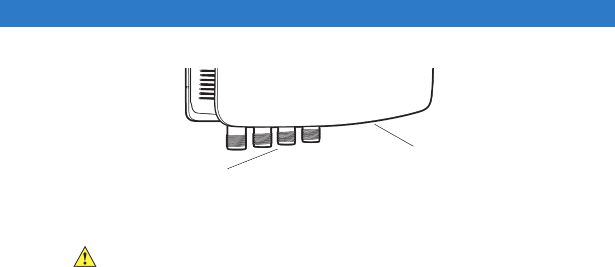
3. Connect the antenna to antenna Port 1. See Figure 1-1.
4. Connect the AC power supply to a power outlet and connect to the power port. See Figure 1-1.
5. Wait for the green power LED to stay lit. See System Start-up/Boot LED Sequence on page 3-5 for boot-up
details.
6. Connect the Ethernet cable to the Ethernet port. See Figure 1-1.
Connecting the reader to a subnet that supports DHCP is recommended. This Quick Start procedure is not
guaranteed to work if DHCP is disabled in the reader and if the reader is connected directly to a PC.
1 - 2 FX Series RFID Readers Integrator Guide
Figure 1-1
FX Series RFID Reader Rear Panel Connections
Step 2, Host Name Connect
The product CD provides the Host Name. Connect the reader to the local network and boot it up. See System
Start-up/Boot LED Sequence on page 3-5. The green power LED indicates that the reader is ready.
1. Open a browser. Recommended browsers are IE 6 or Mozilla 3.
2. Enter the host name provided on the CD in the browser (e.g., http://fx7400cd3b0d) and press Enter.
3. The Console Login window appears and the reader is ready.
4. Proceed to Step 3, First Time / Start-Up Login on page 1-3 to log in to the reader.
Port 1 Port 2 Port 3 Port 4 GPIO 24 VD
Antenna Ports (Four Ports, Reverse TNC) USB Power
GPIO 10/100BaseT Ethernet
(with POE)
Reset
NOTE Connect the reader to a network that supports host name registration and lookup to ensure the network
can access the reader using the host name. For instance, some networks can register hostnames
through DHCP. When first connecting to the reader, it is recommended to keep DHCP enabled, although
it is not guaranteed that hostname will work in this case. Use the host name provided on the CD label, or
construct it using the reader MAC address on the reader back label. The host name is a string with prefix
FX7400, followed by the last three MAC address octets. For example, for a MAC address of
00:15:70:CD:3B:0D, use the prefix FX7400, followed by the last three MAC address octets (CD, 3B, and
0D), so the host name is FX7400CD3B0D. Type http://FX7400CD3B0D in the browser address bar to
access the reader.
Getting Started 1 - 3
Step 3, First Time / Start-Up Login
When starting the reader for the first time, set a unique user ID and password and set the region where the reader
operates. Setting the unit to a different region is illegal.
Set the Unique User ID and Password
1. Connect to the reader using a web browser. See Step 2, Host Name Connect on page 1-2. The Default
Settings, Console Login Window appears.
Figure 1-2
Default Settings, Console Login Window
2. Enter admin1 in the User Name: field and enter change in the Password: field. Click Login.
Figure 1-3
Enter Default Settings, Console Login Window
NOTE Entering the unique user ID and password disables the factory default settings. Contact Motorola
Enterprise Mobility support if you forget the user ID and password.
See
Service Information on page
xi
.
1 - 4 FX Series RFID Readers Integrator Guide
3. From the Administrator Console, select Configure Reader and Region.
Figure 1-4
Reader Administrator Console Main Menu
Step 4, Set Region
Set the region of operation. Setting the unit to a different region is illegal.
Figure 1-5
Configure Region Settings Window
NOTE Region configuration is not available for readers configured to operate in the United States region (under
FCC rules). In this case, skip this step.
Getting Started 1 - 5
1. In the Region Configuration window, select the region from the drop-down menu.
Figure 1-6
Selecting the Region
2. Select the Communication Standard, if applicable.
3. Select Frequency Hopping, if applicable.
4. Select the appropriate channel(s), if applicable.
5. Click the I understand check box.
6. Click Set Properties to complete the region selection. The Operation Successful window appears.
Figure 1-7
Region Control, Operation Successful Window
1 - 6 FX Series RFID Readers Integrator Guide
7. From the Reader Administrator Console (see Figure 1-4 on page 1-4) select Commit/Revert.
Figure 1-8
Commit/Revert Window
8. Click Discard to discard the region configuration changes made during this session, or click Commit to save the
new region configuration and apply these changes to the reader configuration file.
9. When the commit completes, the Commit Successful window appears.
Getting Started 1 - 7
Step 5, Read Tags
Click Start Inventory on the Reader Operation window to initiate an on-demand scan and/or to enable or disable
polled read points.
The polling state displays the current polling setting - Enabled or Disabled. If enabled from the Administrator
Console, this displays Polling State: Enabled from Web. If enabled from byte stream, this displays Polling State:
Enabled from byte stream.
Figure 1-9
Read Tags Window
•
Click Start Inventory to start inventory operation on the connected antennas.
•
Click Stop Inventory to stop the ongoing inventory operation.
•
Select the Clear Tag List check box to clear the current tag list.
The list of tags appears in a table with the following attributes for each tag:
•
EPC Id: Unique tag EPC ID.
•
TagSeen Count: Number of times the tag is identified on the specific antenna.
•
RSSI: Received Signal Strength Indication.
•
Antenna Id: Antenna ID on which the tag is seen.
•
FirstSeen time stamp: UTC time (in microseconds) when the tag was first seen.
•
LastSeen time stamp: UTC time (in microseconds) when the tag was last seen.
NOTE Enable JVM support on the browser for this page to function properly. See Appendix C, Java Upgrade
Procedures.

1 - 8 FX Series RFID Readers Integrator Guide
Chapter 2 Getting Started
Introduction
This chapter provides an overview of RFID technology and components, and describes the FX Series reader and
its features.
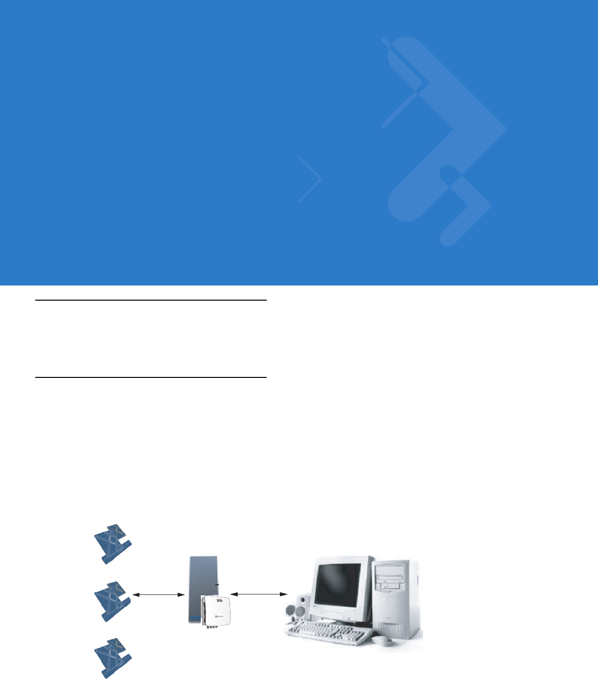
RFID Technology Overview
RFID (Radio Frequency Identification) is an advanced automatic identification (Auto ID) technology that uses radio
frequency signals to identify tagged items. An RFID tag contains a circuit that can store data. This data may be
pre-encoded or can be encoded in the field. The tags come in a variety of shapes and sizes.
A typical RFID system consists of transponders (called tags), readers, and antennas. To read a tag the reader
sends out radio frequency waves (using attached antennas). This RF field powers and charges the tags, which are
tuned to receive radio waves. The tags use this power to modulate the carrier signal. The reader interprets the
modulated signal and converts the data to a format for computer storage. The computer application translates the
data into an understandable format.
Figure 2-1
RFID System Elements
Reader and Antenna
Host Computer
Physical/Network
Connection
RF Wave and
Response
Tags

2 - 2 FX Series RFID Readers Integrator Guide
RFID Components
Motorola RFID solutions offer low cost, long read range, and a high read rate. These features provide real time,
end-to-end visibility of products and assets in the factory, distribution center, retail outlet, or other facility. A typical
Motorola RFID system consists of the following components:
•
Silicon based RFID tags that attach to retail products, vehicles, trailers, containers, pallets, boxes, etc.
•
Different antenna types to support applications such as dock door (area antennas), conveyor.
•
Readers power and communicate with the tags for data capture and provide host connectivity for data
migration.
Tags
Tags contain embedded chips that store unique information. Available in various shapes and sizes, tags, often
called transponders, receive and respond to data requests. Tags require power to send data, and are available with
two power options:
•
Active Tags: typically powered by light-weight batteries and have limited life.
•
Passive Tags: the RFID reader generates an RF field that powers the tag. Passive tags are much lighter, less
expensive, and have a much longer life than active tags.
Antennas
Antennas transmit and receive radio frequency signals. A read point is the RF range of an antenna.
Readers
Readers communicate with the tags and transfer the data to a host computer. Readers also provide features such
as filtering, CRC check, and tag writing. The FX Series readers read Gen2 (dense reader mode) RFID tags.
Getting Started 2 - 3
FX Series RFID Readers
The Motorola FX Series RFID readers are intelligent, C1G2 UHF RFID readers with RFID read performance that
provides real-time, seamless EPC-compliant tags processing. The FX Series RFID readers are designed for indoor
inventory management and asset tracking applications in large scale deployments. The readers can host
third-party, customer-driven embedded applications.
The FX Series RFID readers are based on Motorola's strategic FX Series reader platform and are easy to use,
deploy, and manage. The readers offer a variety of options for connecting to corporate networks using Ethernet or
USB connections. Features include:
•
ISO 18000-6C standard (EPC Class 1 Gen 2)
•
Dense reader mode capable
•
Cost-effective
•
Enterprise-class performance
•
Application-specific set-up for ease of installation
•
Power over Ethernet (POE) to eliminate the need for a power drop
•
SSL/SSH based security for secure data transmission
•
Attractive small package
•
Low total cost of ownership (TCO)
•
Windows® CE
•
Support for custom or third-party applications
•
Feature set for event and tag management
Figure 2-2
FX RFID Reader
2 - 4 FX Series RFID Readers Integrator Guide
The reader provides a wide range of features that enable implementation of complete, high-performance,
intelligent RFID solutions.
The FX Series RFID reader configurations include either two or four
monostatic
antenna ports. The monostatic
ports are used only with monostatic antennas.
Versions and Kits
The FX Series RFID readers are available in either a 2-port or a 4-port version, individually (reader and mounting
bracket) or in a kit that includes the reader, the mounting bracket, an antenna and a power supply:
•
2-Port reader, mounting bracket
•
2-Port kit (reader, mounting bracket, antenna, cable, PSU)
•
4-Port reader, mounting bracket
•
4-Port kit (reader, mounting bracket, antenna, cable, PSU)
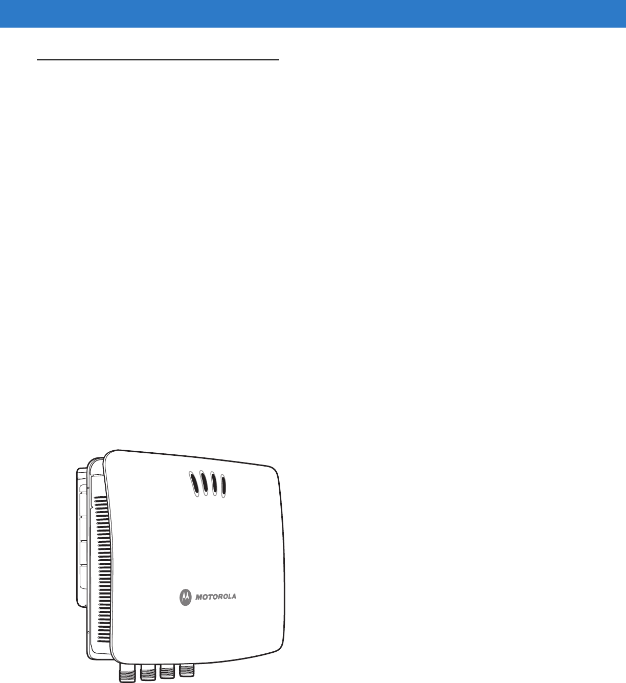
FX Series RFID Reader
Figure 2-3
FX Series RFID Reader
Antenna Ports (Reverse TNC)
LEDs
Rear Panel
Getting Started 2 - 5
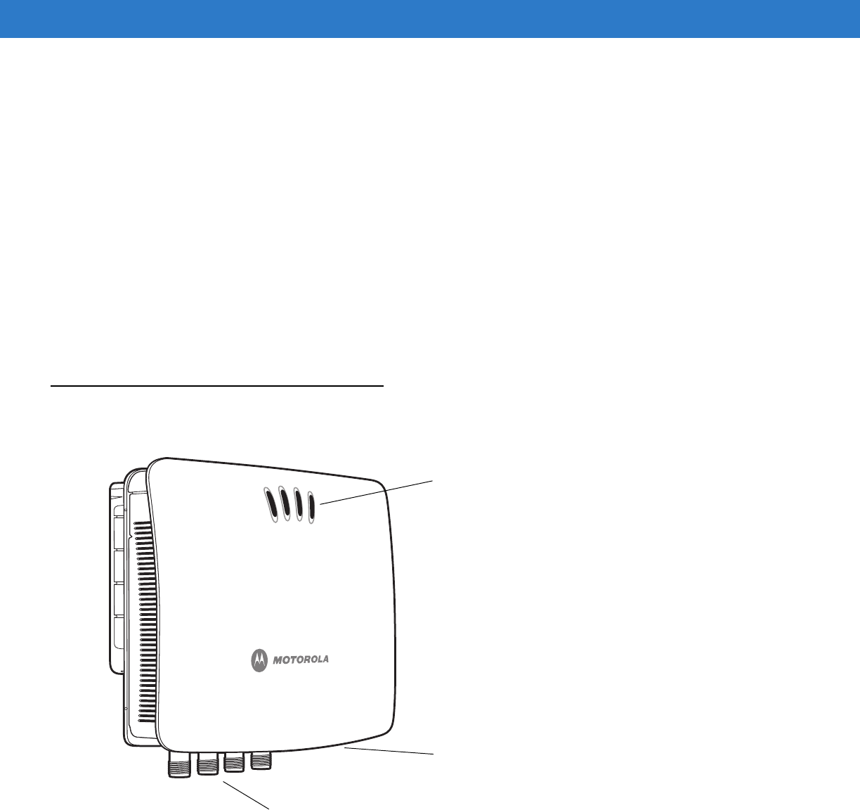
Figure 2-4
FX Series RFID Reader Rear Panel Connections
FX Series RFID Readers Rear Panel
Port 1 Port 2 Port 3 Port 4 GPIO 24 VD
Antenna Ports (Four Ports, Reverse TNC) USB Power
GPIO 10/100BaseT Ethernet
(with POE)
Reset
CAUTION Use only parts provided with the FX Series RFID readers, or Motorola approved/recommended parts.
Substituting other cables or parts can degrade system performance, damage the reader, and/or void
the warranty.
Table 2-1
FX Series RFID Readers Rear Panel Description
Port Description
Antenna Ports
(Reverse TNC)
Two port version: Connect up to two antennas.
Four port version: Connect up to four antennas.
See
Table A-1 on page A-1
for the maximum antenna gains and RF output powers for both
US/Canada and EU.
Reset To reset the reader insert a paper clip into the reset hole, press and hold the reset button for not
more than 2 seconds. This resets the reader, but retains the user ID and password.
GPIO Insert a DE15 serial cable to connect to external devices.
USB ActiveSync is enabled by default on the USB client port. Use Visual Studio to use the USB port
for development. Use a remote display tool to access the Windows CE graphical interface.
Advanced users can disable and enable ActiveSync via a registry change in Windows CE,
and can create a custom communication protocol on the USB port.
10/100BaseT
Ethernet
Insert a standard RJ45 Ethernet cable to connect to an Ethernet network with or without POE
capability. Insert a cross-connect Ethernet cable to connect to a local computer.
Power DC connector connects to a Motorola approved power supply AC adapter (varies depending on
the country). Maximum power 24 VDC, 1.2 A.
2 - 6 FX Series RFID Readers Integrator Guide
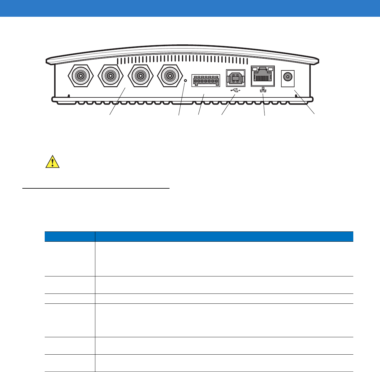
FX Series RFID Readers LEDs
The reader LEDs indicate reader status as described in Table 2-2. For the LED boot up sequence see System
Start-up/Boot LED Sequence on page 3-5.
Figure 2-5
FX Series RFID Readers LEDs
Table 2-2
LED Indications
LED Function Color/Status Description
PWR Power Off
Red Solid
Red Flashing
Amber Solid
Green Solid
Reader is powered off
Booting
Firmware upgrade
Application initialization after booting
Reader is powered on and operational
ACTV Activity Off
Amber Flashing
Green Flashing
No RF operations
On for 500mSec indicates another tag operation
On for 500mSec indicates a tag is inventoried or read
STAT Status Off
Red Solid
Red Flashing
Green Flashing
No errors or GPIO events
Firmware update failure
On for 500 mSec indicates an error in RF operation
On for 500 mSec indicates a GPI event
APP Application Green/Red/Amber Controlled through LLRP
PWR ACTV STAT APP

Getting Started 2 - 7
FX Series RFID Readers Features
Configuration and Upgrading
Use the Administrator Console to reconfigure the reader. See Chapter 4, Administrator Console. The reader can
also accept new firmware and configuration updates.
Tag Management
The Administrator Console provides the Read tags feature. See Read Tags on page 4-18. Use client applications
based on Showcase II, Motorola EMDK (Enterprise Mobility Development Kit), or LLRP (EPCGlobal Low Level
Reader Protocol) for additional tag management operations such as Write, Lock, Filtering, Event Management and
Kill.
Device Management
Quick Backup and Recovery
Use a web browser to back up and restore reader configuration by downloading the configuration XML file. Use the
Administrator Console to download the file to the reader.
SNMP Integration
The reader can send real time notification of specific events and failures to the SNMP server.
Security
User Level Security
Use this feature to assign different access levels to users, allowing them to perform necessary tasks without
compromising security. The reader recognizes three user access levels:
•
View - view reader configuration settings.
•
Admin - view and edit configuration settings and perform administrative tasks such as updating reader
firmware.
Logging
The reader keeps a log of all system-related activities for security and troubleshooting. The log includes
time-stamped system activities such as login attempts and hardware failures. Use the log to pinpoint problems, to
facilitate quick resolution, and to identify administrators who may require additional training to prevent future
problems. See System Log on page 4-32.
Dense Reader Mode
The Gen 2 (or Class 1 G2) Dense Reader Mode allows the reader operate in a range of environments where
multiple readers operate simultaneously, where few readers operate, or just one reader operates.

2 - 8 FX Series RFID Readers Integrator Guide
Connection Options
The reader provides flexibility for connecting to networks with an Ethernet connection. Access each reader from
anywhere on the network with the unique host name or IP address. See Connect to the Reader on page 4-3.
Physical Interfaces
At the physical layer, the FX Series readers use an Ethernet interface (as the default) for command and data
communication with the reader.
The USB port enables ActiveSync on the USB client port by default. Use the USB port for development using
Visual Studio, and use a remote display tool to access the Windows CE graphical interface.
Advanced users can disable and enable ActiveSync via a registry change in Windows CE, and can create a
custom communication protocol on the USB port.

Chapter 3 Installation and Communication
Introduction
This chapter includes the following FX Series RFID reader installation and communication procedures:
•
Unpack the Reader on page 3-1
•
Installation on page 3-2
•Mounting and Removing the Reader on page 3-2
•Connecting Antennas on page 3-4
•Powering the Reader on page 3-5
•Verifying Hardware Functionality on page 3-5
•
Communications Connections on page 3-6
•Ethernet Connection on page 3-6
•USB Connection on page 3-7
Unpack the Reader
Remove the reader from the shipping container and inspect it for damage. Keep the shipping container, it is the
approved shipping container and should be used if the reader needs to be returned for servicing.

3 - 2 FX Series RFID Readers Integrator Guide
Installation
The FX Series reader has several installation options, including installation with or without the mounting plate,
and/or powering either using the AC power supply or POE.
Mounting Tips provides recommendations on locating the reader with respect to environmental conditions and
utilities locations. Mounting and Removing the Reader on page 3-2 provides detailed mounting procedures. Mount
the reader with and without the provided mounting plate, however Motorola recommends using the mounting plate
whenever possible.
Connecting Antennas on page 3-4 describes how to connect the antennas. Mounting Tips on page 3-2 also
provides information on locating the antennas with regard to the reader.
Powering the Reader on page 3-5 and AC Power Supply on page 3-5 provide information on reader power options
and Verifying Hardware Functionality on page 3-5 provides a checkout to verify reader functionality.
The Communications Connections on page 3-6 provide communications information for the reader.
Mounting and Removing the Reader
Mounting Tips
Mount the reader in any orientation. Consider the following before selecting a location for the FX Series reader:
•
Mount the reader indoors, in operating range and out of direct sunlight, high moisture, and/or extreme
temperatures.
•
Mount the reader in an area free from electromagnetic interference. Sources of interference include
generators, pumps, converters, non-interruptible power supplies, AC switching relays, light dimmers, and
computer CRT terminals.
•
Mount the reader within 15 feet of the antennas.
•
Ensure that power can reach the reader.
•
The recommended minimum horizontal mounting surface width is 7 1/2 inches. However, the unit can mount
on surfaces as narrow as 6 inches (in locations where unit overhang is not an issue). For vertical mounting
the unit can mount on a surface as small as 6 inches by 6 inches.
•
Mount the reader onto a permanent fixture, such as a wall or a shelf, where it is not disturbed, bumped, or
damaged. The recommended minimum clearance on all sides of the reader is five inches.
•
Use a level for precise vertical or horizontal mounting.
CAUTION The FX Series RFID readers must be professionally installed.
WARNING!When installing the antenna ensure a minimum separation distance of 9.1 in (23 cm)
between the antennas and all persons.

Installation and Communication 3 - 3
Mounting Using the Mounting Plate
1. Position the mounting plate on a flat surface (wall or shelf). Position the release tab on the top. See Figure 3-1.
2. Mark the hole locations using the mounting plate as a guide. See Figure 3-1. Remove the mounting plate and
drill holes (appropriate for the surface material) at the marked locations.
Figure 3-1
Mounting Plate, Front
3. Reposition the mounting plate over the mounting holes and secure using the supplied fasteners (as
appropriate for the surface material).
4. Position the reader by aligning the markers on the metal base plate and the wall bracket, positioning the
key-slot holes over the mounting screws. Gently slide the reader down (see Figure 3-1) to lock into place.
5. To remove the reader, press the release tab and slide the reader up while gently pulling out.
NOTE For wood surfaces, drill two 1/8" diameter by 7/8" deep holes. For drywall/masonry surfaces, drill two
3/16" diameter by 7/8" deep (min) holes and install using the provided anchors.
Release Tab
Mounting Holes
Screw Head Stops
(4 typical)
CAUTION Use a hand screw driver to install the mounting plate (do not use a power driver). Do not use
excessive torque, and tighten the screws so that they are just snug on the screw head stops (see
Figure 3-1). If the reader does not engage the mounting plate, loosen the screw(s) 1/8 to 1/4 turn and
try again.
NOTE Mount the reader with the cable connections up or down, depending on the installation requirements.
3 - 4 FX Series RFID Readers Integrator Guide
Direct Mounting (Without the Mounting Plate)
To mount the unit without using the mounting bracket:
1. Use the mounting bracket as a template to locate the holes, or locate and mark the holes on 4 3/16” centers,
+/- 1/32”.
2. For wood surfaces, drill two 1/8" diameter by 7/8" deep holes on 4.192" centers. For drywall/masonry surfaces,
drill two 3/16" diameter by 7/8" deep (min) holes on 4.192" centers and install using the provided anchors.
3. Position the reader with the key-slot holes over the mounting screws and gently slide the reader down to lock
into place.
4. Adjust the screw head height to assure a snug fit. Or if the screws are accessible from the back, use machine
screws with a lock washer/nut and tighten the nut (from the back) to secure the reader.
Connecting Antennas
To connect the antennas to the reader (see Figure 3-2):
1. Attach the antenna reverse TNC connector to an antenna port.
2. Repeat Step 1 to connect the remaining antennas to the reader.
3. Secure the cable using wire ties. Do not bend the cable.
CAUTION Not using the mounting plate can result in a read performance issue at elevated temperatures.
Also, if not using the mounting plate, secure the reader to prevent it from coming off of the mounting
screws.
WARNING!When installing the antenna ensure a minimum separation distance of 9.1 in (23 cm)
between the antennas and all persons.
CAUTION Power off the reader before connecting antennas. See Powering the Reader on page 3-5. Never
disconnect the antennas while the reader is powered on or reading tags. This can damage the reader.
CAUTION Do not turn on the antenna ports from a host when the antennas are not connected.
CAUTION Maximum antenna gain (including any cable loss) cannot exceed 6 dBiL.
CAUTION For installations where the antennas are mounted externally to the building, the screen of the coaxial
cable must be connected to earth (grounded) at the entrance to the building. This should be done in
accordance with applicable national electrical installation codes. In the U.S., this is required by Section
820.93 of the National Electrical Code, ANSI/NFPA 70.
Table 3-1
Antenna Gain and Radiated Power
FX Series US EU
Max Conducted RF Power + 30dBm +29.2dBm
Max Antenna Gain Allowed (including cable loss) + 6dBiL + 6dBiL
Max Radiated Power Allowed 4W EIRP 2W ERP
Installation and Communication 3 - 5
Figure 3-2
FX Series RFID Reader Antenna Connection
Powering the Reader
To power the reader:
1. Insert either the POE Ethernet connector or the power supply barrel connector into the appropriate reader
power (see Figure 2-4 on page 2-5). Rotate the power supply barrel connector to lock the connector in place.
2. Apply power to the power supply. The green Power LED stays on to indicate the reader is powered and ready.
See System Start-up/Boot LED Sequence on page 3-5.
To power down the reader:
1. Unplug the power supply from its power source to remove power. The green Power LED turns off to indicate
that the device is off and the system is not operational.
2. Remove the connector from the reader power port.
AC Power Supply
The Motorola approved AC power supply connects to the power port on the FX Series reader using a locking
connector (see Figure 2-4 on page 2-5). The power supply is compatible with:
•
120V 60 Hz (North America)
•
230V 50 Hz (International excluding Japan)
•
100V 50/60 Hz (Japan).
Verifying Hardware Functionality
System Start-up/Boot LED Sequence
See Figure 2-5 on page 2-6 for LED locations. During system start-up:
1. All LEDs turn green.
2. All LEDs turn off and the PWR LED turns red.
3. The PWR LED turns off and then turns green.
4. When the sequence completes the green PWR LED remains on and all other LEDs are off.
Antenna Ports (Reverse TNC)
Rear Panel
CAUTION Connect the antennas before supplying power to the reader.

3 - 6 FX Series RFID Readers Integrator Guide
Communications Connections
Use a standard Ethernet connection or a POE Ethernet connection to connect the FX Series reader to a host or
network.
Ethernet Connection
The reader communicates with the host using an Ethernet connection (10/100Base-T Ethernet cable). This
connection allows access to the Administrator Console, used to change reader settings and control the reader.
With a wired Ethernet connection (10/100Base-T cable), power the FX Series reader using either the reader
Motorola AC power supply, or by Power-Over-Ethernet through the Ethernet cable.
Ethernet: Power through AC Outlet
The FX Series reader communicates to the host through a 10/100Base-T Ethernet cable and receives power
through a Motorola AC power supply.
1. Route the Ethernet cable.
2. Route the power cable.
3. Terminate the Ethernet cable according to Table A-2 on page A-3.
4. Connect the Ethernet cable to the LAN port on the FX Series reader. See Figure 2-4 on page 2-5.
5. Connect the other end of the Ethernet cable to the host system LAN port.
6. Connect the Motorola AC power supply to a wall outlet.
7. Insert the power supply barrel connector into the FX Series reader power port. See Figure 2-4 on page 2-5.
8. Verify that the unit booted properly and is operational. SeeVerifying Hardware Functionality on page 3-5.
9. On a networked computer, open an internet browser and connect to the reader. See Connect to the Reader on
page 4-3.
10. Log in to the Administrator Console. See Administrator Console Login on page 4-8.
Ethernet: Power through POE
The POE installation option allows the FX Series reader to communicate and receive power on the same
10/100Base-T Ethernet cable. See Figure 2-4 on page 2-5.
1. Terminate the Ethernet cable according to Table A-2 on page A-3.
2. Connect the Ethernet cable to the FX Series reader Ethernet / Bias-T port. See Figure 2-4 on page 2-5.
3. Connect the other end of the Ethernet cable to the Bias-T (POE) module.
4. Connect a patch cable from the Bias-T (POE) module to the host system LAN port.
5. Verify that the unit booted properly and is operational. SeeVerifying Hardware Functionality on page 3-5.
CAUTION Do not use POE in conjunction with an external power supply connected to the power port on the FX
Series reader.
CAUTION Do not connect to PoE networks outside the building.

Installation and Communication 3 - 7
6. On a networked computer, open an internet browser and connect to the reader. See Connect to the Reader on
page 4-3.
7. Log in to the Administrator Console. See Administrator Console Login on page 4-8.
USB Connection
The USB port enables ActiveSync on the USB client port by default. Use the USB port for development using
Visual Studio, and use a remote display tool to access the Windows CE graphical interface.
Advanced users can disable and enable ActiveSync via a registry change in Windows CE, and can create a
custom communication protocol on the USB port.
Reading Tags
Read Test
After the reader powers up, test the reader. See Verifying Hardware Functionality on page 3-5.
1. Enable tag read using the web-based Administrator Console. See Read Tags on page 4-18.
2. Control the reader through a real time application such as Showcase II.
3. Present a tag so it is facing the antenna and slowly approach the antenna until the activity LED turns green,
indicating that the reader read the tag. See Figure 2-5 on page 2-6. The distance between the tag and the
antenna is the approximate read range.
NOTE The initial release does not expose RFID tag data over the USB client port. Subsequent releases may
change the USB default support. The software release notes will announce USB support in the future.
NOTE For optimal read results, do not hold the tag at an angle or wave the tag, as this can cause the read
distance to vary.

3 - 8 FX Series RFID Readers Integrator Guide

Chapter 4 Administrator Console
Introduction
This chapter describes the FX Series Administrator Console functions and procedures. Access the Administrator
Console using a web browser from a host computer, and use this to manage and configure the readers. The
Administrator Console main window and support windows have four areas, each containing unique information
about the reader.
•
Selection Menu - selects the function window
•
Primary Information Window - provides the primary function information
•
Product Identification Header - identifies the product
•
Help Information Window:
•provides detailed information to support the primary information window
•Use the scroll bar to scroll through information
•Use the toggle on/off button to turn on/off the help information window
Figure 4-1
Reader Administrator Console Main Menu
Selection Menu Primary Information Window Product Identification Header
Help Information Window
Toggle On/Off Button
Help Information Window Scroll Bar
Help Information Window
4 - 2 FX Series RFID Readers Integrator Guide
Managing the FX Series RFID Readers
The reader must be powered up (see System Start-up/Boot LED Sequence on page 3-5) and connected to an
accessible network. The power LED is green indicating the reader is ready. If the green power LED is not lit, reset
the reader. See Reset Reader on page 4-2.
The install/startup sequence is:
1. Installation on page 3-2
2. Communications Connections on page 3-6
3. Connect to the Reader on page 4-3
4. Administrator Console Login on page 4-8
a. First Time / Start-Up Login on page 4-8
b. Normal Login on page 4-11
Profiles
Use profiles for multiple reader deployments to save configuration time, as only a few APIs are needed to
completely configure a reader. See Reader Profiles on page 4-26.
Reset Reader
To reset the reader, press and hold the reset button for not more than 2 seconds. See Figure 2-4 on page 2-5 for
the reset button location. This resets the reader and retains the user ID and password. The reader reboots. See
System Start-up/Boot LED Sequence on page 3-5.
NOTE The recommended browsers are IE 6 and Mozilla 3. These browsers have been tested and validated to
work properly. Other browsers may or may not work properly.
NOTE The screens and windows are provided for illustration purposes only and may differ from actual screens.
The applications described may not be available on (or applicable to) all devices.
Procedures are not device specific and are intended to provide a functional overview.
NOTE Hard rebooting the reader (disconnecting power) is not recommended. A hard reboot discards all the tag
events and system log information.

Administrator Console 4 - 3
Connect to the Reader
When the reader is powered up, connect to the network in one of two ways:
1. Host Name Connect on page 4-3
2. IP Address Connect on page 4-4
There are three ways to assign an IP address to the reader:
1. Using DHCP on the network
2. APIPA (Automatic Private IP Addressing) on page 4-4
3. Statically assign an IP
Any method of assigning the IP supports connection using hostname or IP address. Alternatively, connect the
reader directly to a local computer using Automatic Private IP Addressing (APIPA). See APIPA (Automatic Private
IP Addressing) on page 4-4.
Host Name Connect
The product CD provides the host name. Connect the reader to the local network and boot it up. See System
Start-up/Boot LED Sequence on page 3-5. The green power LED indicates that the reader is ready.
1. Open a browser. Recommended browsers are IE 6 or Mozilla 3.
2. Enter the host name provided on the CD in the browser (e.g., http://fx7400cd3b0d) and press Enter.
3. The Console Login window appears and the reader is ready.
4. Proceed to Administrator Console Login on page 4-8 to log in to the reader.
NOTE When using APIPA, the FX Series reader cannot communicate with computers on different subnets, or
with computers that do not use automatic private IP addressing.
NOTE Connect the reader to a network that supports host name registration and lookup to ensure the network
can access the reader using the host name. For instance, some networks can register hostnames
through DHCP. When first connecting to the reader, it is recommended to keep DHCP enabled, although
it is not guaranteed that hostname will work in this case. Use the host name provided on the CD label, or
construct it using the reader MAC address on the reader back label. The host name is a string with prefix
FX7400, followed by the last three MAC address octets. For example, for a MAC address of
00:15:70:CD:3B:0D, use the prefix FX7400, followed by the last three MAC address octets (CD, 3B, and
0D), so the host name is FX7400CD3B0D. Type http://FX7400CD3B0D in the browser address bar to
access the reader.
For a network that does not support host name registration and lookup, use the Showcase II auto
discovery feature to get the IP address, and use the IP address connect method.
4 - 4 FX Series RFID Readers Integrator Guide
IP Address Connect
Use the IP address to connect to the reader. Connect the reader to the local network and boot it up. See System
Start-up/Boot LED Sequence on page 3-5. The green power LED indicates that the reader is ready.
1. Open a browser. Recommended browsers are IE 6 or Mozilla 3.
2. Enter the IP address in the browser (e.g., http://157.235.88.99) and press Enter.
3. The Console Login window appears and the reader is ready.
4. Proceed to Administrator Console Login on page 4-8 to login to the reader.
APIPA (Automatic Private IP Addressing)
If a DHCP server is not available, the FX Series readers can use APIPA to automatically provide a unique network
IP address. The FX Series readers can then use TCP/IP to communicate with other computers also using an
APIPA-generated IP address.
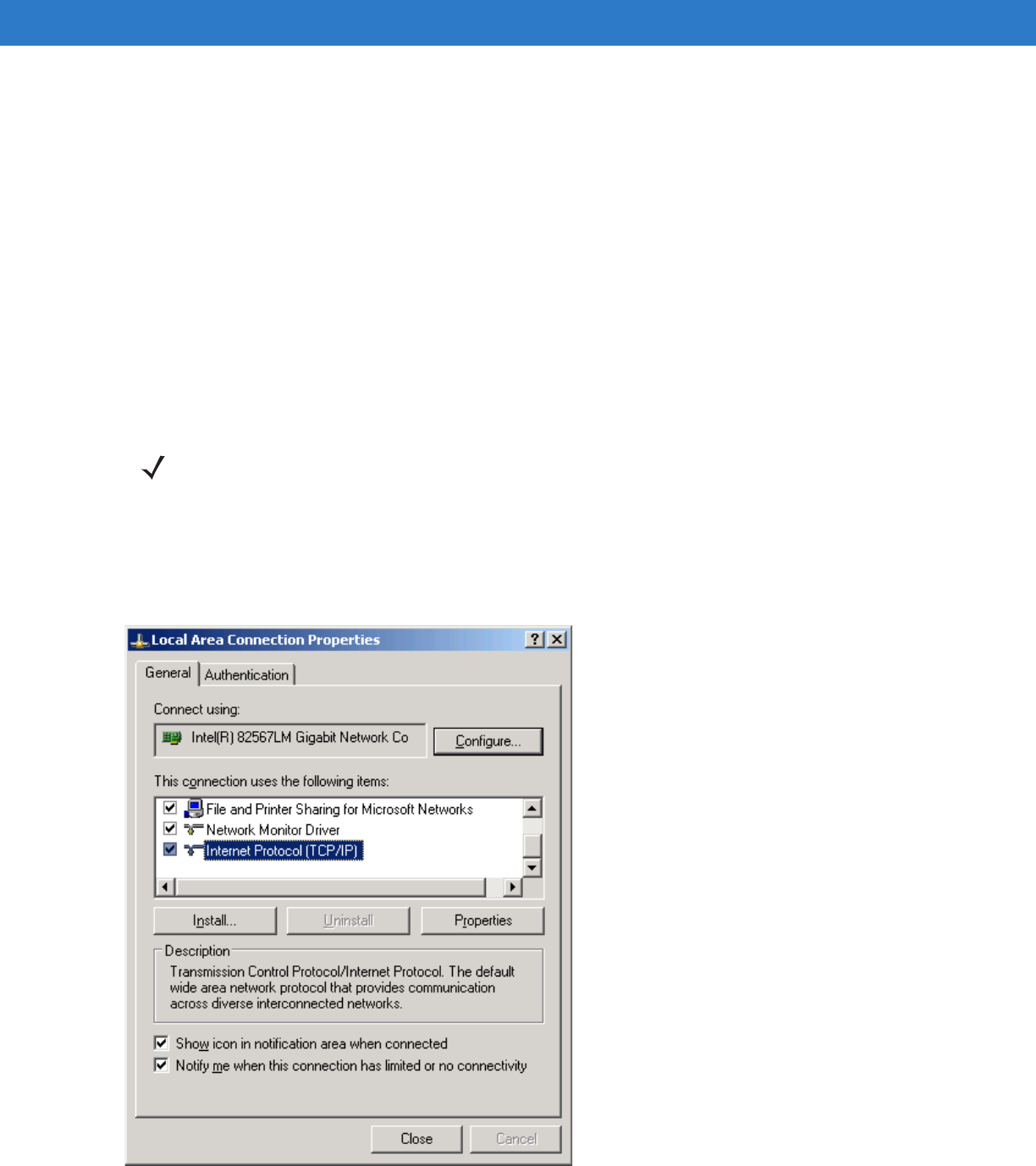
1. Go to Start > Settings > Network Connections > Local Area Connection Status and select Properties. Set the
DHCP to On (even though no DHCP server is reachable) and open a browser window.
2. In the General tab, select Internet Protocol (TCP/IP) and click Properties.
Figure 4-2
Set Internet Protocol (TCP/IP) Window
NOTE APIPA does not function if DHCP is disabled in the reader. When using APIPA, the FX Series reader
cannot communicate with computers on different subnets, or that do not use automatic private IP
addressing. Automatic private IP addressing is enabled by default. For additional information go to:
http://support.microsoft.com/ and search on APIPA
Administrator Console 4 - 5
3. Connect the FX Series reader to a local computer using a standard Ethernet cable.
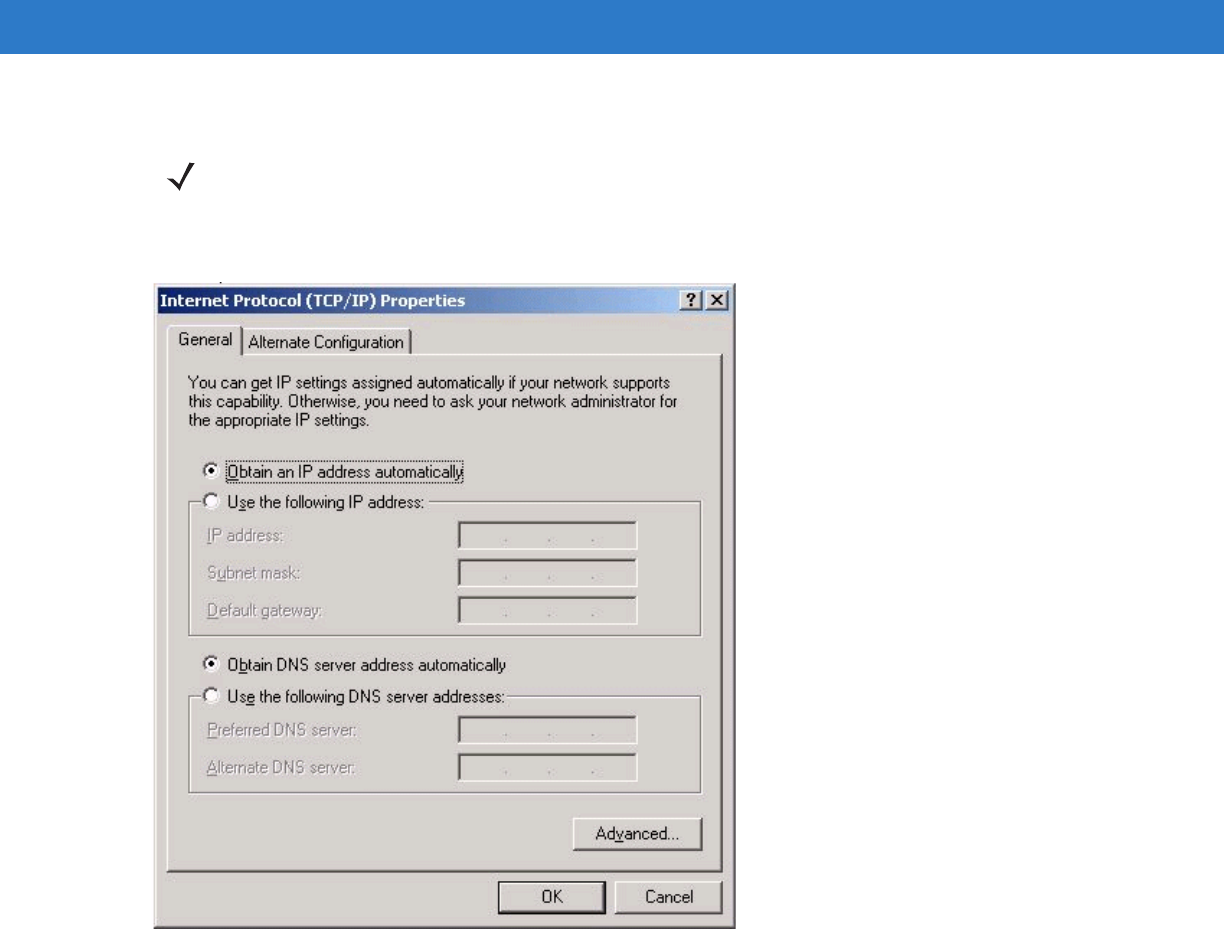
4. In the Properties window, select the General tab, select Obtain an IP Address automatically, and select Obtain
DNS Server address automatically.
Figure 4-3
TCP/IP General Properties Window
NOTE Do not use an Ethernet crossover cable.
4 - 6 FX Series RFID Readers Integrator Guide
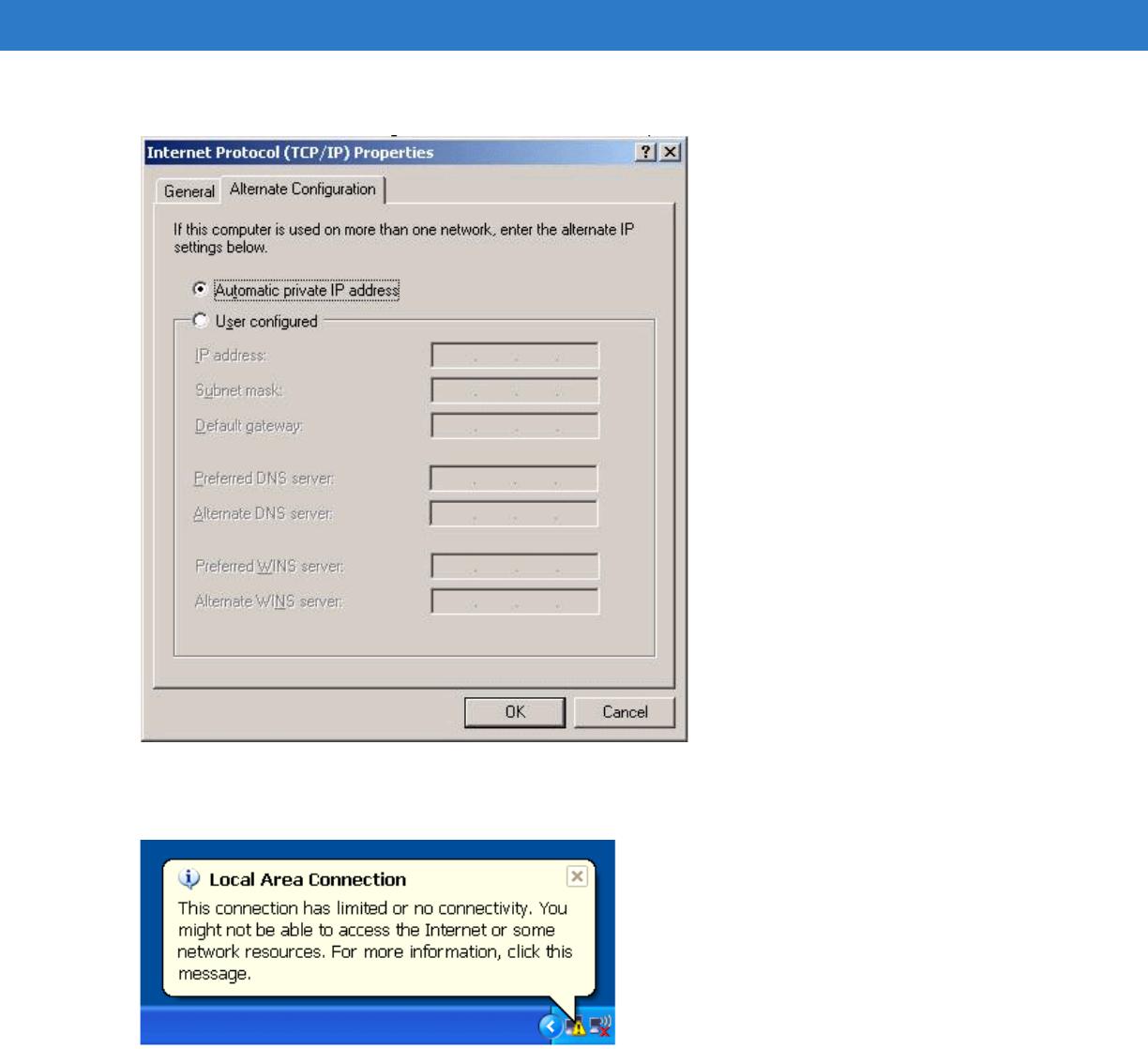
5. Confirm that the Alternate Configuration tab is set to Automatic Private IP address (Windows default).
Figure 4-4
TCP/IP Alternate Configuration Window
6. Wait until the computer indicates the connection has limited connectivity.
Figure 4-5
Limited Connectivity Window
7. Confirm that the computer IP address is now set to the 169.254.x.y (where x.y is the last six characters of the
FX Series reader MAC address) with a subnet mask of 255.255.0.0.
8. The CD provides the reader host name. Enter the host name into the browser (e.g., http://fx7400cd3b0d) and
press Enter. The local computer connects to the reader.
9. The Console Login window appears and the reader is ready.
10. Proceed to Administrator Console Login on page 4-8 to log in to the reader.
Administrator Console 4 - 7
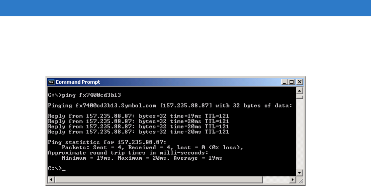
IP Address
The Administrator Console provides the reader IP address. See Figure 4-1 on page 4-1. To obtain the reader IP
address without logging into the reader, open a command window and ping the reader host name. See Host Name
Connect on page 4-3.
Figure 4-6
IP Ping Window
4 - 8 FX Series RFID Readers Integrator Guide
Administrator Console Login
Use a web browser on a local computer to access the Administrator Console. See Managing the FX Series RFID
Readers on page 4-2 for the install/setup sequence. The reader has a unique first time startup sequence that
requires the installer to set a unique user ID and password and to set the region (regulatory requirement).
First Time / Start-Up Login
When starting the reader for the first time, set a unique user ID and password and set the region of reader
operation. Setting the reader to a different region is illegal.
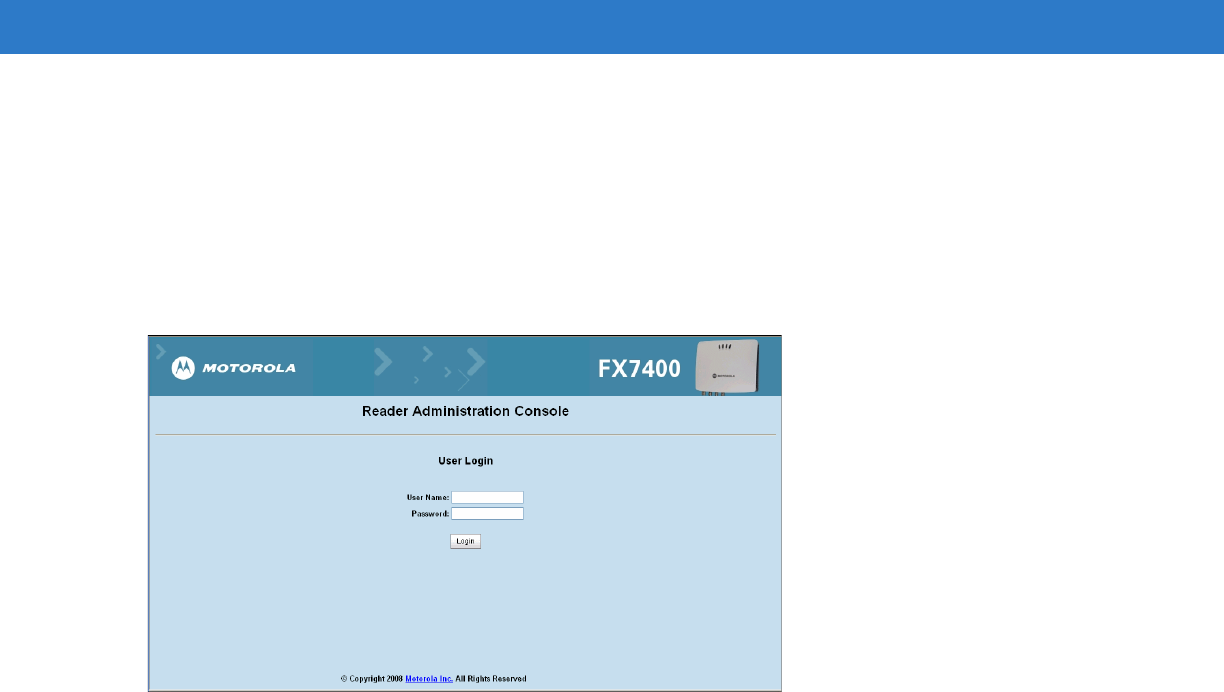
Log In with Default User ID and Password
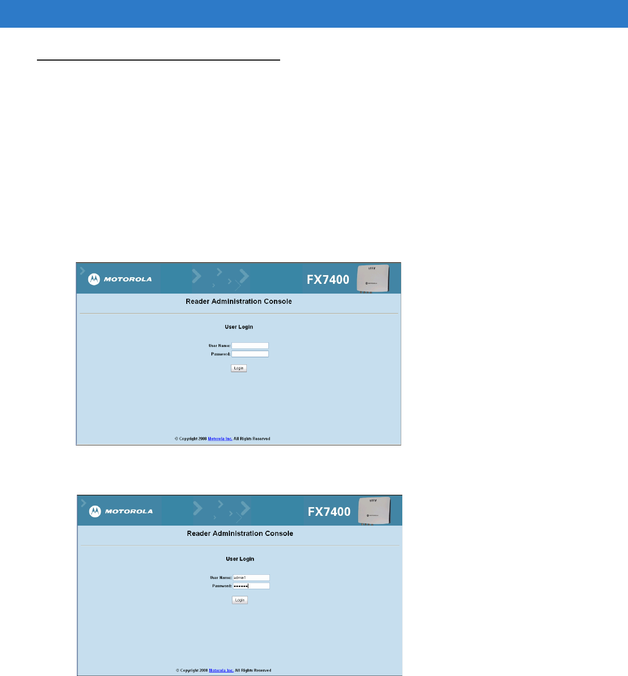
1. Connect to the reader with a web browser. See Connect to the Reader on page 4-3. The User Login window
appears.
Figure 4-7
User Login Window
2. Enter admin1 in the User Name: field and change in the Password: field and click Login.
Figure 4-8
Enter User Name and Password
Administrator Console 4 - 9
3. From the Administrator Console, select Configure Reader and Region. See Set Region.
Figure 4-9
Reader Administrator Console Main Menu
Set Region
Set the region of operation. Setting the unit to a different region is illegal.
Figure 4-10
Configure Region Settings Window
NOTE Region configuration is not available for readers configured to operate in the United States region (under
FCC rules). In this case, skip this step.
4 - 10 FX Series RFID Readers Integrator Guide
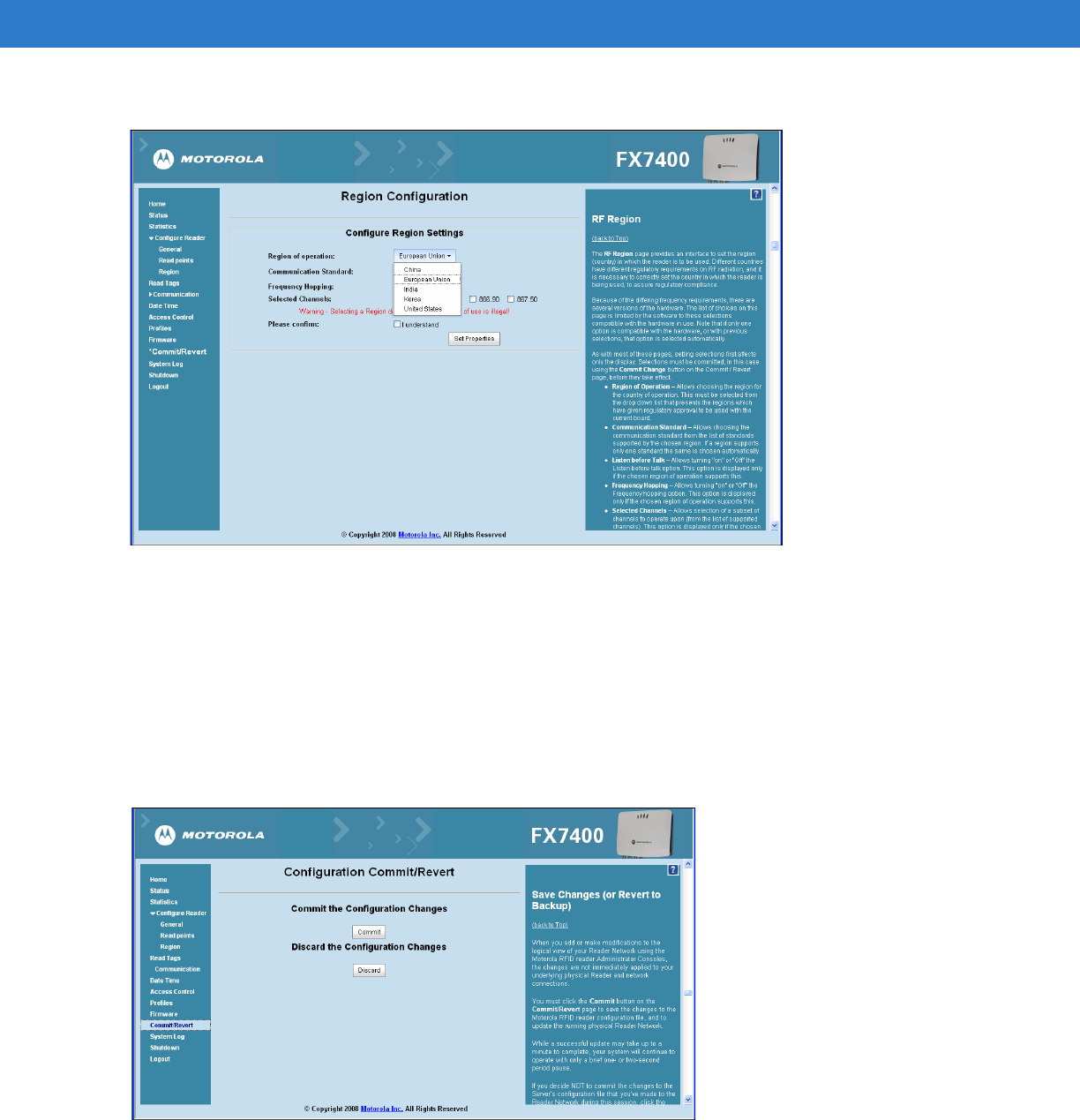
1. In the Configure Region Settings window, select the region from the drop-down menu.
Figure 4-11
Selecting the Region
2. Select the Communication Standard if applicable.
3. Select Frequency Hopping, if applicable.
4. Select the appropriate channel(s), if applicable.
5. Click the I understand check box.
6. Click Set Properties to complete the region selection. The Operation Successful window appears.
7. From the Reader Administrator Console (see Figure 4-9 on page 4-9) select Commit/Revert.
Figure 4-12
Commit/Revert Window
8. Click Discard to discard the new region configuration changes, or Commit to apply the changes to the reader
configuration file.
Administrator Console 4 - 11
9. When the commit completes, the Commit Successful window appears. The region is now set and stored in the
reader.
Normal Login
After setting the user ID, password, and region, the reader defaults to the normal login procedure.
1. Connect to the reader with a web browser. See Connect to the Reader on page 4-3. The User Login window
appears.
Figure 4-13
User Login Window
2. Enter the User Name: and Password: in the appropriate fields and click Login. The reader Administrator
Console Main Menu window appears (Figure 4-14).
4 - 12 FX Series RFID Readers Integrator Guide
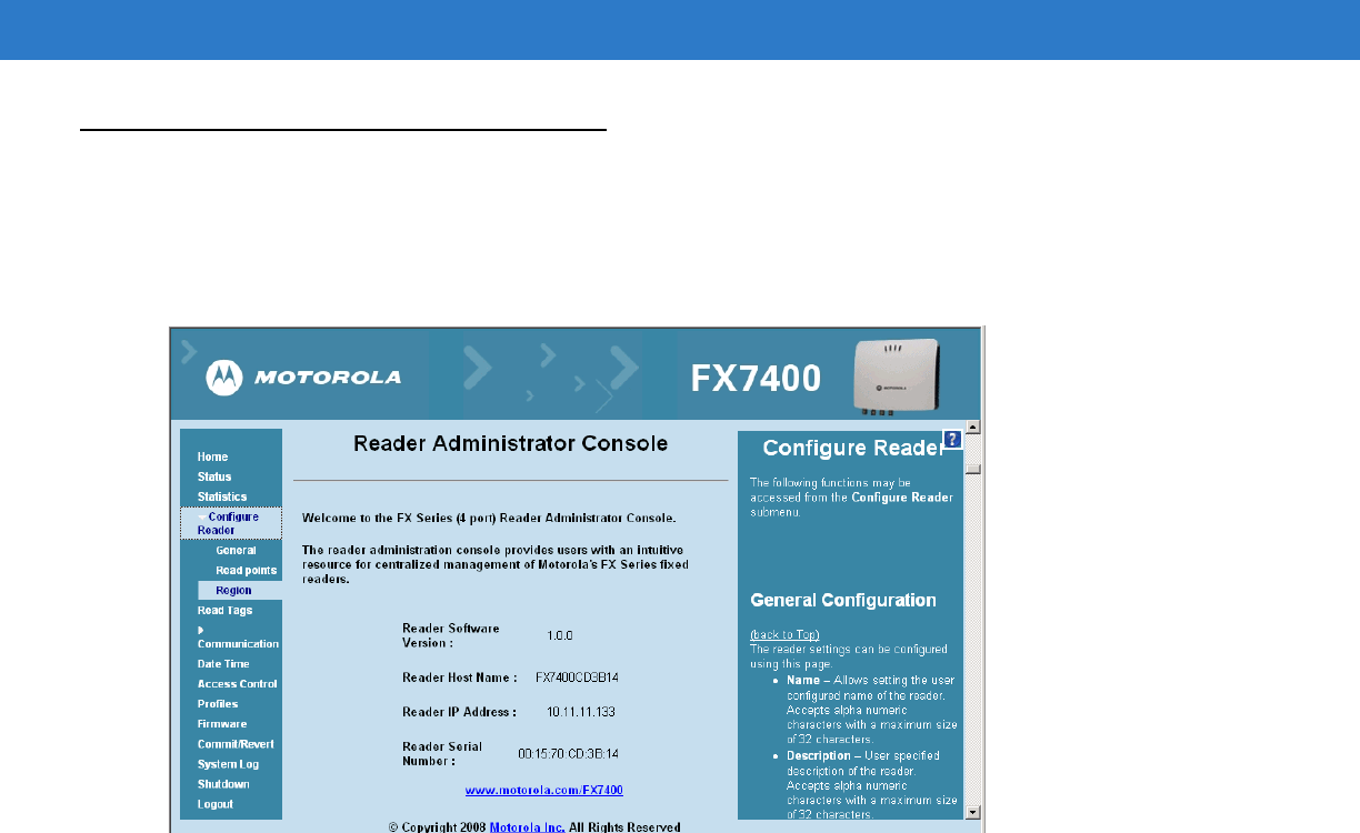
Reader Administrator Console
Use a web browser on a local computer to access the Administrator Console reader settings and functions. See
Managing the FX Series RFID Readers on page 4-2 for the install/setup sequence. The reader Administrator
Console Main Menu window appears after successfully logging into the reader. See Administrator Console Login on
page 4-8.
Figure 4-14
Reader Administrator Console Main Menu
Administrator Console Option Selections
Click the menu item to select:
•
Status - see Status on page 4-13
•
Statistics - see Reader Statistics on page 4-17
•
Configure Reader - see Configure Reader on page 4-14
•Click General to enter general reader parameters
•Click Read Points to enter the read point settings
•Click Region to set the region of operation
•
Read Tags - see Read Tags on page 4-18
•
Communication - see Communication Settings on page 4-19
•Click Communication > Network - see Configure Network Settings on page 4-19
•Click Communication > LLRP - see LLRP Communications Protocol on page 4-21
•Click Communication > SNMP - see SNMP Settings on page 4-23
•
Date/Time - see System Time Management on page 4-24
•
Access Control - see Manage Users on page 4-25
•
Profiles - see Reader Profiles on page 4-26
Administrator Console 4 - 13
•
Firmware - see Firmware Version/Update on page 4-28
•
Commit/Revert - see Commit/Revert on page 4-31
•
System Log - see System Log on page 4-32
•
Shutdown - see Shutdown on page 4-33
•
Logout - click Logout to immediately log out of the Administrator Console
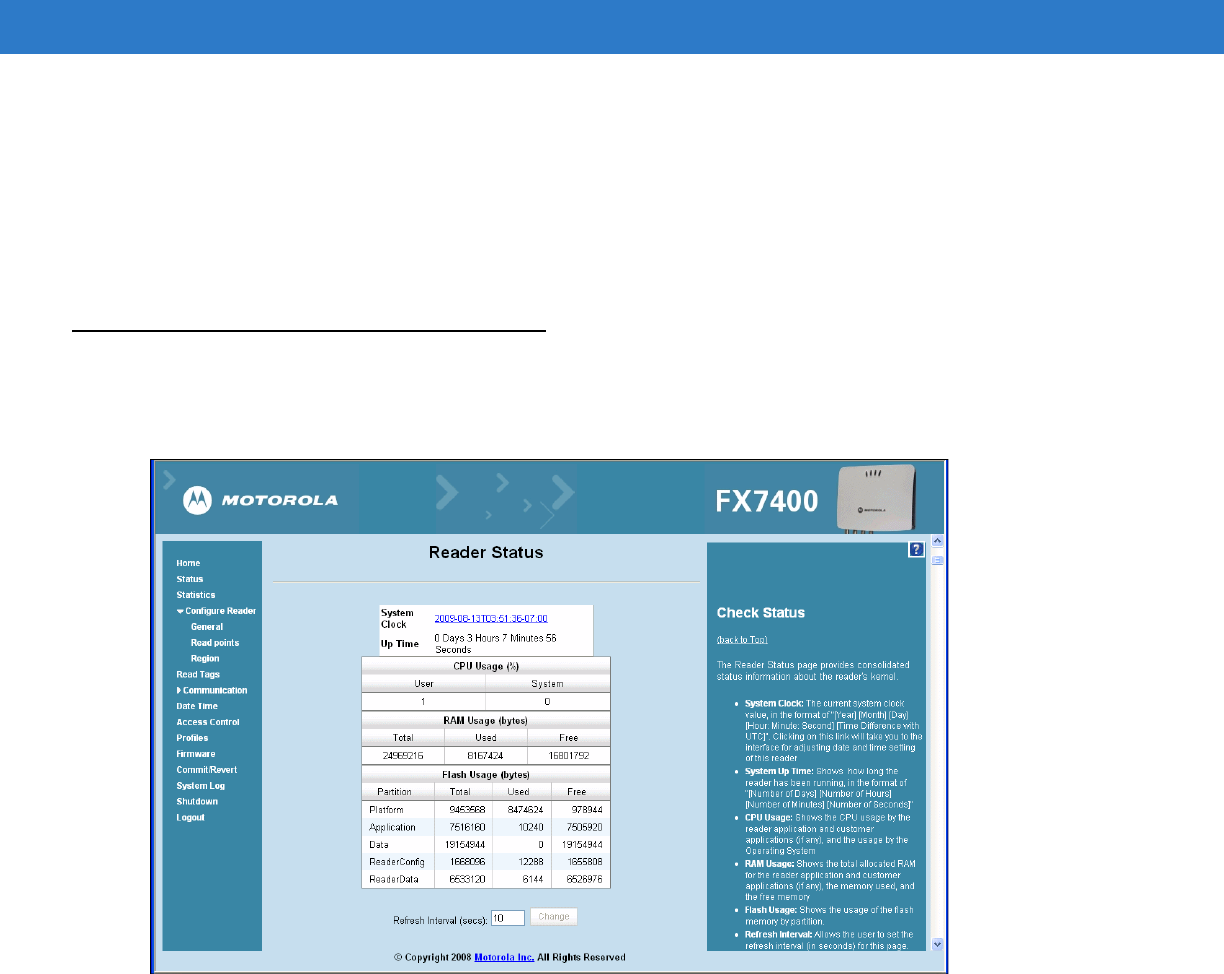
Status
Click Status on the console main menu to view the Reader Status window. This window displays information about
the reader and read points (antennas).
Figure 4-15
Reader Status Window
The Reader Status window provides consolidated reader status information:
•
System Clock - The current system clock value, in the format [Year] [Month] [Day] [Hour: Minute: Second]
[Time Difference with UTC]. Click the link to adjust the reader date and time settings.
•
Up Time - Displays how long the reader has been running, in the format of [Number of Days] [Number of
Hours] [Number of Minutes] [Number of Seconds].
•
CPU Usage - Displays the CPU usage, the user applications (if any), and the system usage.
•
RAM Usage - Displays the total allocated RAM for the reader, the memory used, and free memory.
•
Flash Usage - Displays the flash memory usage by partition.
•
Refresh Interval - Sets the refresh interval (in seconds) for the page. The status information refreshes every N
seconds (where N is the user configured value for the refresh interval). The minimum refresh interval value is
10 seconds.
4 - 14 FX Series RFID Readers Integrator Guide
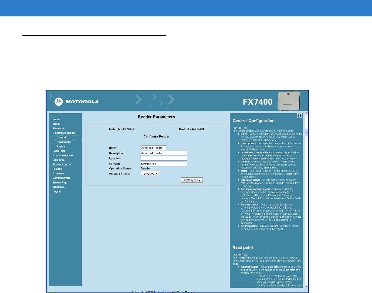
Configure Reader
Use the Configure Reader submenu to access the following functions.
Reader Parameters
Configure reader settings using this window.
Figure 4-16
Configure Reader
•
Name - Sets the reader name. Accepts up to 32 alphanumeric characters.
•
Description - Describes the reader. Accepts up to 32 alphanumeric characters.
•
Location - Provides information on the reader location. Accepts up to 32 alphanumeric characters.
•
Contact - Name of the reader manager contact. Accepts up to 32 alphanumeric characters.
•
Operation Status - Displays the reader current operation status (Enabled, Disabled, or Unknown).
•
Serial Connection Timeout - Timeout value (in seconds) for the serial console of the reader. 0 indicates that
there is no timeout for the serial console. The minimum acceptable value for this field is 15 seconds.
•
Antenna Check - Controls the antenna sensing feature on the reader. Disabled indicates that the reader does
not attempt to check if an antenna is connected on the ports. When Enabled, the reader monitors the
presence of an antenna on the port and only transmits RF if an antenna is connected.
•
Set Properties - Sends the changes to the reader.
These settings only affect the display. Use Commit/Revert on page 4-31 to save the changes.
Administrator Console 4 - 15
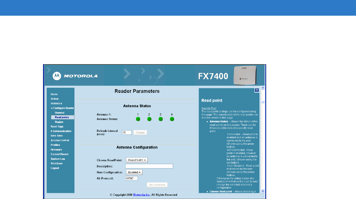
Configure Read Point
Click Read points on the console main menu to view the Antenna Status and Configuration window. Use this window
to configure the read point settings and view the current read points state.
Figure 4-17
Configure Read Points
Antenna Status
Displays the status of the reader read points. Click the read point status button to view and/or change the selected
antenna configuration.
•
Connected (green button):
Read point is enabled and an antenna is connected to the port.
•
Not Connected (red button):
Read point is enabled, no antenna is connected to the port.
•
User Disabled (yellow button):
Read point is disabled by the user.
Antenna Configuration
•
Choose ReadPoint - Select a readpoint (or all) to display the configuration.
•
Description - User-specified read point description. Accepts up to 32 alphanumeric characters.
•
User Configuration - Enables or disables a specific read point. Disabling a read point blocks RF operation
using the port/antenna.
•
Air Protocol - Displays the list of air protocols the read point supports. Currently only EPC class1 GEN2 air
protocol is supported.
•
Set Properties - Click Set Properties to send the changes to the reader.
These settings only affect the display. Use Commit/Revert on page 4-31 to save the changes.
4 - 16 FX Series RFID Readers Integrator Guide
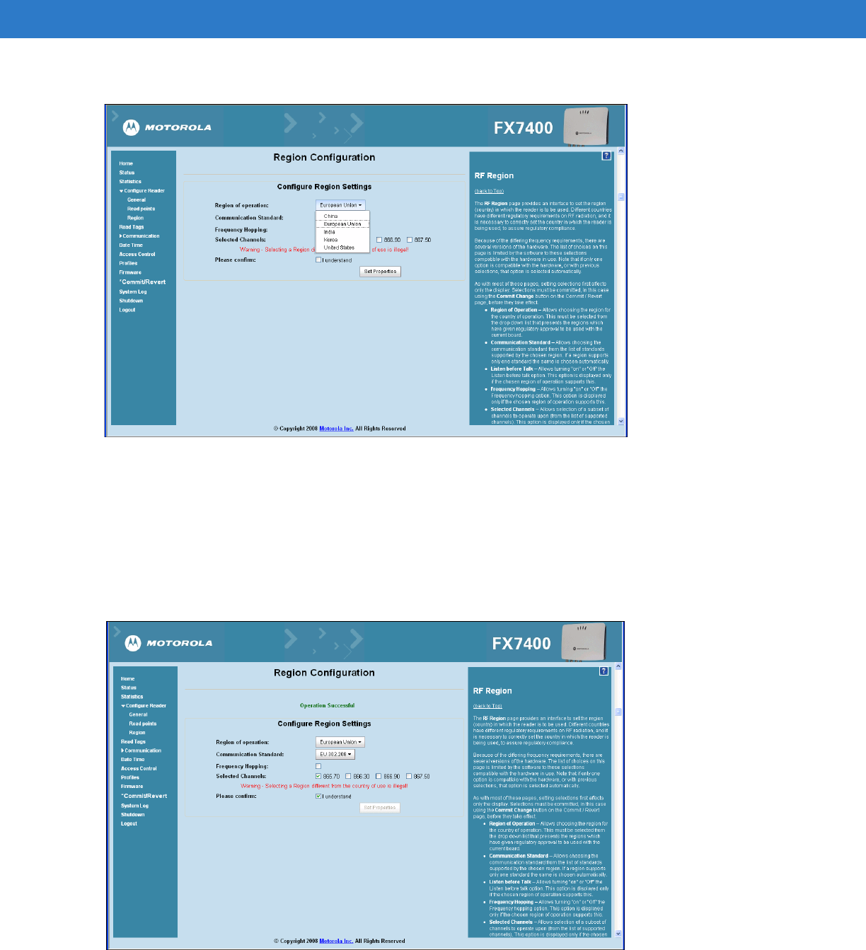
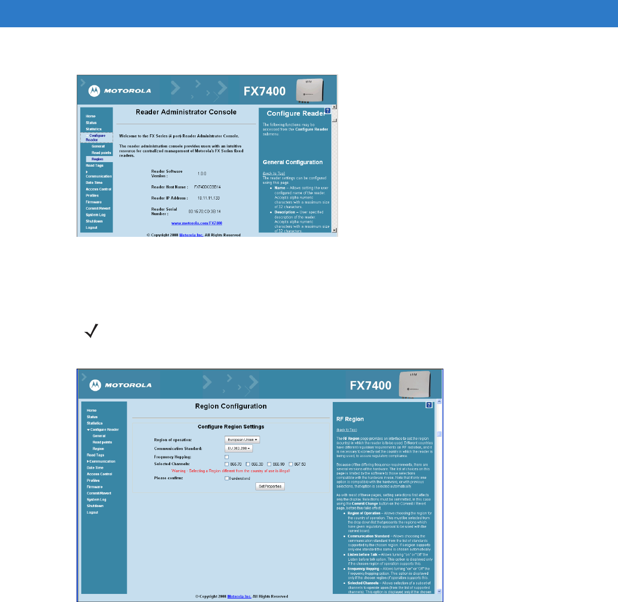
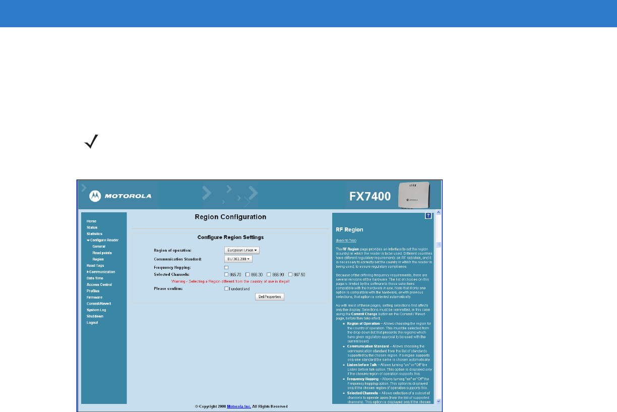
Configure RF Region
Different countries have different RF regulatory requirements. To assure regulatory compliance, set the reader for
specific regulatory requirements in the country of reader operation using the Configure Region Settings page. The
choices on the page are limited to the selections compatible with the reader.
Figure 4-18
Configure Region Settings Window
•
Region of Operation - Sets the country of operation. Select this from the drop-down list which includes
countries which have regulatory approval to use with the current board.
•
Communication Standard - Sets the communication standard from the list of standards chosen region
supports. If a region supports only one standard, it is automatically selected.
•
Frequency Hopping - Check to select frequency hopping.
•
Selected Channels - Sets the appropriate channel(s).
•
Please confirm - Check the I understand check box.
•
Set Properties - Sends the changes to the reader. Confirm that the choices are in compliance with local
regulatory requirements by checking the I understand check box.
These settings only affect the display. Use Commit/Revert on page 4-31 to save the changes.
Additional Options
•
Listen before Talk - Turns On or Off the listen before talk option. This option appears only if the chosen region
of operation supports this.
•
Frequency Hopping - Turns On or Off the Frequency hopping option. This option appears only if the chosen
region of operation supports this.
NOTE Region configuration is not required for readers configured to operate in the United States region (under
FCC rules).
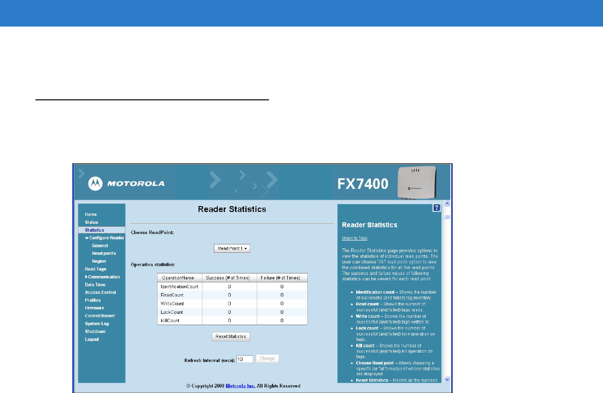
Administrator Console 4 - 17
•
Selected Channels - Selects a subset of channels to operate on (from the list of supported channels). This
option appears only if the chosen region of operation supports this function.
Reader Statistics
The Reader Statistics window provides options to view the statistics of individual read points or combined statistics
for all read points, including the success and failure values of statistics for each read point.
Figure 4-19
Reader Statistics Window
•
Choose ReadPoint - Select a specific read point or select All from the drop-down list to display the statistics.
•
IdentificationCount - Displays the number of successful (and failed) tag inventory.
•
ReadCount - Displays the number of successful (and failed) tags reads.
•
WriteCount - Displays the number of successful (and failed) tags written to.
•
Lockcount - Displays the number of successful (and failed) lock operation on tags.
•
KillCount - Displays the number of successful (and failed) kill operation on tags.
•
Reset Statistics - Resets all the success and failure counts for all the read points.
•
Refresh Interval - Use to set the refresh interval (in seconds) for this page. The statistics information for the
chosen read point is refreshed every N seconds (where N is the user-configured value for the refresh
interval). The minimum value of the refresh interval is 10 seconds. Input a new value and click Change to set
a new interval.
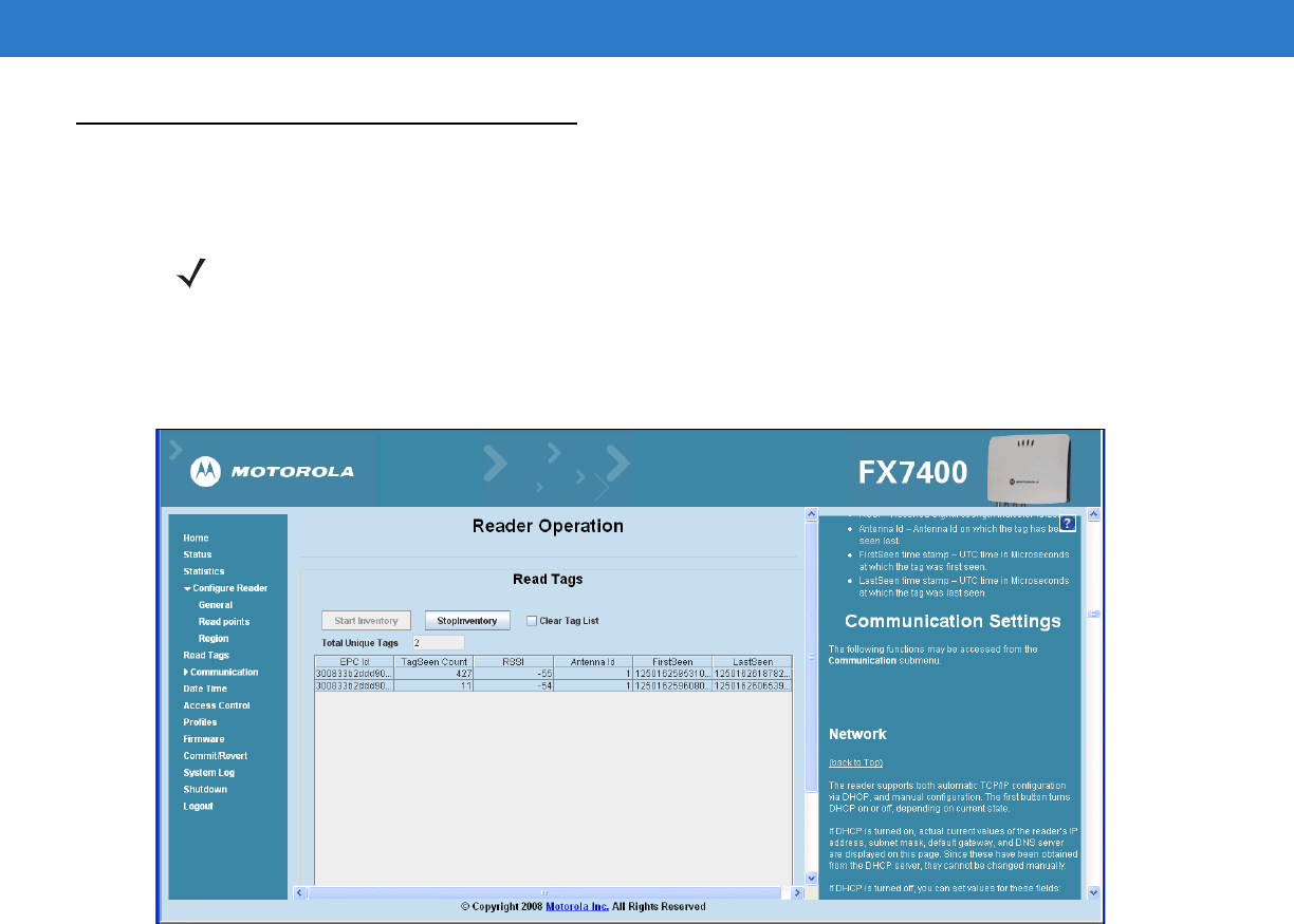
4 - 18 FX Series RFID Readers Integrator Guide
Read Tags
Click Start Inventory to initiate an on-demand scan and/or to enable and disable polled read points.
The polling state displays the current polling setting (Enabled or Disabled).
Enabling polling from the Administrator console displays the Polling State: Enabled from Web message. Enabling
polling from byte stream displays the Polling State: Enabled from byte stream message.
Figure 4-20
Read Tags Window
•
Start Inventory - Starts inventory operation on the connected antennas.
•
Stop Inventory - Stops the ongoing inventory operation.
•
Clear Tag List - Clears the current tag list.
The list of tags appears in a table with the following attributes for each tag:
•
EPC Id - Unique tag EPC ID.
•
TagSeen Count - Number of times the tag has been identified on the specific antenna.
•
RSSI - Received Signal Strength Indication.
•
Antenna Id - Antenna ID on which the tag is seen.
•
FirstSeen time stamp - UTC time (in microseconds) when the tag was first seen.
•
LastSeen time stamp - UTC time (in microseconds) when the tag was last seen.
NOTE Enable JVM support on the browser in order for this page to function properly. See Appendix C, Java
Upgrade Procedures.
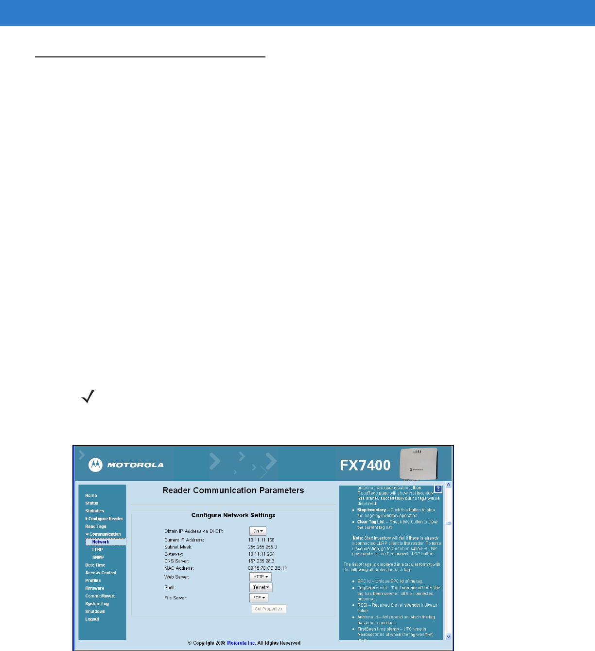
Administrator Console 4 - 19
Communication Settings
Use the Communication submenu to access the following functions.
Configure Network Settings
The reader supports both automatic TCP/IP configuration via DHCP, and manual configuration. The Obtain IP
Address via DHCP: button toggles the DHCP On or Off, depending on the current state.
Turning DHCP on displays the current IP address, subnet mask, default gateway, and DNS server. These values
are obtained from the DHCP server so cannot be manually changed.
To manually set the values, toggle the DHCP to Off and enter the values:
•
Current IP Address (in dotted notation)
•
Subnet Mask (in dotted notation)
•
Gateway (in dotted notation)
•
DNS Server (in dotted notation)
•
MAC Address – Specifies the reader MAC address.
•
Web Server – Configures the web server in either HTTP (unsecure) or HTTPS (secure) mode.
•
Shell – Configures the Shell to either Telnet (unsecure) or SSH (secure) mode, or disables the shell.
•
File Server – Configures the File server to either FTP (unsecure) or FTPS (secure) mode, or disables the
shell.
1. Click Communication > Network. The Configure Network Settings window appears.
Figure 4-21
Configure Network Settings Window
NOTE The network configuration updates only upon clicking Commit. If the commit is not successful, the
system indicates the problem and allows repeating the operation. DHCP and IP address changes update
only upon reader reboot.
4 - 20 FX Series RFID Readers Integrator Guide
2. Change communication related settings by entering information in the text boxes or using the drop-down lists.
See Table 4-1 for descriptions of available options.
3. Click Set Properties.
4. Click Main to return to the Administrator Console main window.
5. Click Commit/Revert. See Commit/Revert on page 4-31.
6. Click Commit to save the changes or Discard to discard the changes. See Commit/Revert on page 4-31.
Table 4-1
Configure Network Settings
Setting Description Possible Values
Obtain IP Address
using DHCP
The Dynamic Host Configuration Protocol server
running on networks can assign a dynamic IP
address to the host and readers. Contact the
system administrator to determine if the network
supports DHCP.
Select the
On
or the
Off
button.
Current IP Address If manually assigning an IP address to the reader,
check with the system administrator to ensure the IP
address is valid in the network.
IP address to assign to the reader.
Subnet Mask A mask used to determine to what subnet an IP
address belongs.
IP address dynamically assigned or
user-entered.
Gateway The reader uses this IP address to access another
network.
Depends on network configuration.
DNS Server The reader uses the Domain Name System (DNS)
IP address to translate domain names.
Depends on network configuration.
MAC Address Reader MAC address.
Web Server Select the port type.
Shell Select the Shell type. Configure the Shell to either
Telnet (unsecure) or SSH (secure) mode, or disable
the shell.
File Server Configure the file server to either FTP (unsecure) or
FTPS (secure) mode, or disable the shell.
Checked (enabled) / unchecked
(disabled).
Administrator Console 4 - 21
LLRP Communications Protocol
From the Administrator Console (see Figure 4-1 on page 4-1) click Communication > LLRP. The Configure LLRP
Settings window appears (Figure 4-22). To be compatible with older releases, LLRP is not enabled by default.
LLRP is not active unless the changes are committed by clicking Commit on the Commit/Revert page. A successful
commit activates LLRP. By default, LLRP activates in server mode listening on port 5084.
Figure 4-22
Configure LLRP Settings Window
The LLRP Service Settings Window provides LLRP Status and specific LLRP configuration parameters. The current
state (running or not running) appears next to the LLRP Status.
LLRP-specific configuration parameters are separate from other parameters related to communications. The
configurable LLRP parameters are listed in Table 4-2.
NOTE When the reader operates in LLRP server mode, LLRPConnect does not appear on the web page. Only
DisconnectLLRP appears (it is greyed if there is no LLRP client connected to the reader). DisconnectLLRP
and ConnectLLRP are mechanisms to connect the reader to an LLRP client or disconnect the reader from an
LLRP client. When the reader is operating in LLRP Client mode, the ConnectLLRP is enabled to allow
connection to the LLRP host. Once connection is successful in this mode, the DisconnectLLRP is enabled to
allow disconnecting from the host.
4 - 22 FX Series RFID Readers Integrator Guide
Configuration options when LLRP in the reader is in Client mode:
•
Reconnect to the server – Enable to attempt reconnection to the specified server if the connection is lost.
Disable to not attempt reconnection if the connection is lost.
•
Server IP – Configures the IP address of the server.
•
Client Port – Configures the LLRP host port to connect to. Default is 5084.
•
Connect Status – Indicates whether or not the reader is connected to the LLRP host. This button toggles
between ConnectLLRP and DisconnectLLRP. Click ConnectLLRP to initiate an LLRP connection to the
host server.
•
To select the LLRP Client mode, check the LLRP Client Mode check box. This uses LLRPClient IP and
LLRPClient/Server Port values to connect to the client.
•
When operating in LLRP server mode, incoming requests from the client use only the LLRP Port value as the
listening port. After setting the parameters, they persist across reader reboots.
Use the Connect LLRP/Disconnect LLRP button to immediately connect and disconnect LLRP from host.
Table 4-2
LLRP Communication Configuration Options
Setting Description Possible Values
LLRP Status Displays the current state of the LLRP server on the reader.
Indicates whether or not the LLRP is running.
Running
Not Running
Operation Mode Sets the LLPR mode in the reader. Server
Client
Client Port Configures the LLRP listening port on the reader. The default is
5084.
Connect Status Indicates the LLRP client connect status as connected or
disconnected. Click the button to toggle between connected or
disconnected status. This button is grayed out if there is no client
connected.
ConnectLLRP
DisconnectLLRP
NOTE The web console parameters that affect LLRP are:
•
Region Control
•
Enable/disable antenna check
•
Monostatic configuration using advanced read point configuration page
•
Enable/disabled state of a read point class
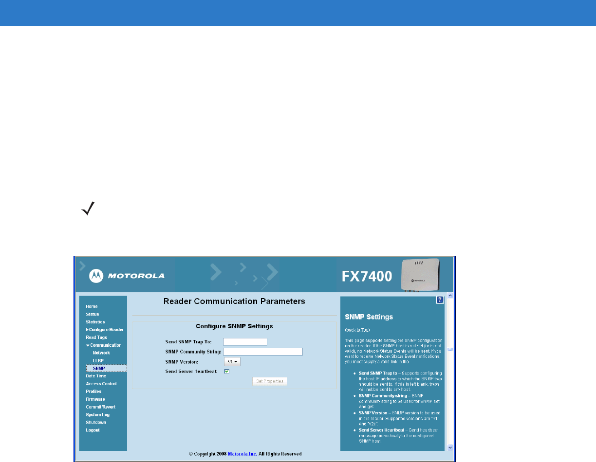
Administrator Console 4 - 23
SNMP Settings
Configure the SNMP host settings to allow sending Network Status Events and receiving Network Status Event
notifications:
•
Send SNMP Trap To - Configures the host IP address to which the SNMP trap is sent. Leave this blank to send
no traps to any host.
•
SNMP Community String - SNMP community string to use for SNMP set and get.
•
SNMP Version - SNMP version to use in the reader. Supported versions are V1 and V2c.
•
Send Server Heartbeat - Sends heartbeat message periodically to the configured SNMP host.
Figure 4-23
Reader Communications Parameters (SNMP) Window
NOTE Send SNMP Trap To and Send Server Heartbeat take effect immediately after clicking Set Properties.
However, perform a Commit to persist the changes. The modified SNMP Community string and SNMP
Version are not affected until the reader reboots.

4 - 24 FX Series RFID Readers Integrator Guide
System Time Management
Use the Date/Time page to set the date and time value or to specify an NTP synchronization server. To specify an
NTP server, enter the NTP Server IP address in the NTP Server Address box, and click Set NTP Server Address.
Perform a Commit to affect the change.
To adjust the time manually, select the value for the local time and click the Set Date and Time. The reader clock
resets to the exact value provided (if the operation is successful or, an appropriate message displays the error). Set
time zones (including use of Daylight Savings) from this page. The date/time and time zone changes take effect
immediately and do not require a Commit.
To set the date and time:
1. Click Date Time in the Administrator Console window. The System Time Management window appears.
Figure 4-24
System Time Management Window
2. To synchronize the clock with a particular SNTP server, enter the server IP address in the SNTP Server
Address: field, click Set SNTP Parameters, and perform a Commit (see Commit/Revert on page 4-31).
3. To set the system time manually, use the drop-down lists to select units of time, then click Set Date and Time.
4. Use the Time Zone: drop-down list to set the time zone, then click Set Time Zone.
NOTE SNTP (Simple Network Time Protocol) is an Internet standard protocol (built on TCP/IP) that assures
accurate synchronization to the millisecond of computer clock times in a network of computers.
It is essential to have a DNS server configured to allow adding an SNTP server on this page. If using a
static IP address, enter a valid DNS server address in the TCP/IP configuration. If this address is not
present, the reader can not add an SNTP server address from this page. Ensure the DHCP server sets
up the DNS server address while issuing the IP address.
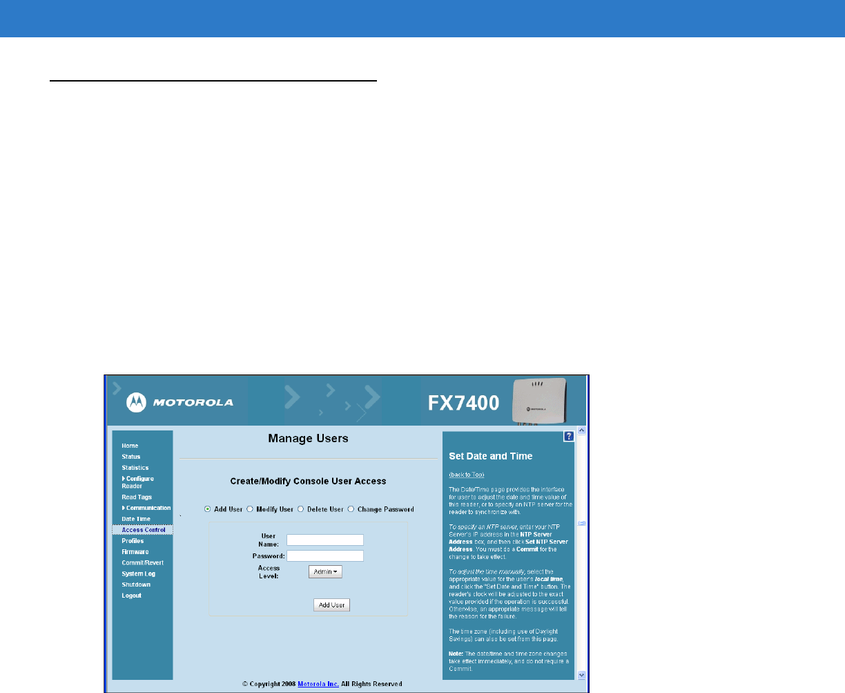
Administrator Console 4 - 25
Access Control
To ensure controlled and secure access to reader Administrator Console functions, designate which users and
computers are authorized to have system access by setting up authorized user accounts. Only users logging in
with a registered user name and password can successfully access Administrator Console functions.
Manage Users
Users must log in and out of the system to ensure that:
•
System access is granted only to authorized users.
•
Only one user is logged in at a time to ensure that multiple users don’t make conflicting changes to the
system. Users who perform no action for a period of time are automatically logged out of the system and
must log in again.
To add or modify users in order to grant rights and permissions:
1. From the Administrator Console, click Access Control.
Figure 4-25
Manage Users Window
2. Select the user access function:
•
Add User - Select this radio button and enter a valid user name and password. Select the desired privilege
level for this user, then click Add User. A valid user name must be unique (assigned to only one user) and
both user name and password must be between one and 32 alphanumeric characters. The user name and
password are case-sensitive. If the entry is successful, the new user name appears in the user drop-down
list. If not successful, the system indicates the problem and allows repeating the operation.
•
Modify User - Select this radio button and select the user name from the user drop-down list. Select the new
access level to set to the user. Click Modify to set the new user access level.
•
Delete User - Select this radio button and select the user name from the user drop-down list. Click Delete
User to remove this user from the system. This user name is now free to use on a new user.
•
Change Password - Select this radio button and select the user name from the user drop-down list. On the
Change Password page, type the old password and the new password (twice) and click Change Password.
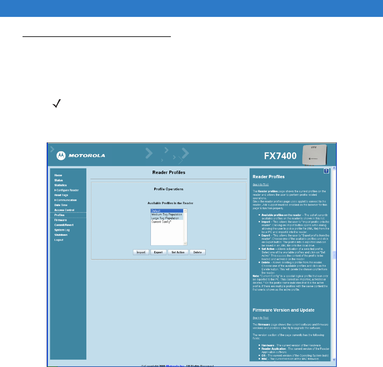
4 - 26 FX Series RFID Readers Integrator Guide
Reader Profiles
The Reader Profiles window shows the current profiles on the reader and allows performing profile-related
operations. Profiles are useful for multiple reader deployments. To configure the readers, manually download the
proper configuration file, or use APIs to programmatically configure many readers quickly. This procedure saves
configuration time because only a few APIs are needed to configure a reader completely.
The Reader Profiles window uses an applet to connect to the reader. The page displays a set of provided
configuration files, or profiles, that a user can re-use and/or modify depending on their specific reader application
or use case. The profiles serve as configuration examples.
Figure 4-26
Reader Profiles Window
The Reader Profiles window functions are:
•
Available Profiles in the Reader - Displays the available reader profiles.
•
Import - Click to open a file dialog and pick a profile (XML file) from the local PC and import it into the reader.
•
Export - Select an available profile and click Export to export profile information and save an .XML file onto
the local drive.
NOTE Enable JVM 1.6 support on the browser in order for this page to function properly. See Appendix C, Java
Upgrade Procedures.

Administrator Console 4 - 27
•
Set Active - Activates a selected profile. Select an available profiles and click Set Active to load the profile
content in the reader. Perform a Commit to complete (see Commit/Revert on page 4-31).
•
Delete - Select an available profile and click Delete to delete the profile.
Create a Custom Profile
The reader includes a set of provided sample profiles. These can not be changed and a new profile with the same
name cannot be imported. Export, modify, and import these profiles under a new name to create customized
profiles. This keeps the original profiles intact to use as a reference.
To view the contents of a profile, select the profile and click Export to export the profile to the PC hosting the
Reader Profiles web page. The profile files are in XML format. Open the file using a text editor application (such as
Notepad) and edit the parameter to modify the reader configuration. Save the modified file under a new name.
Click Import and browse to the modified file and import the file back into the Reader Profile page. This adds the
modified file to the list of profiles. The reader does not perform any checking when importing the file.
To validate the profile file contents, and to activate the modified profile, select the profile and click Set Active. The
reader performs checking on some of the parameter values and notifies the user if it detects an error. If the check
is successful, an asterisk appears on the Commit/Revert menu selection (see Commit/Revert on page 4-31) to
indicate that a commit is required.
NOTE Current Config is a special logical profile that can only be exported to the PC. This cannot be imported,
activated, or deleted. On the profile name indicates that it is the active profile. If there are multiple profiles
with the same content the first one is shown as the active profile.

4 - 28 FX Series RFID Readers Integrator Guide
Firmware Version/Update
The Version Information window displays the current firmware version and allows upgrading to new firmware. From
the Administrator Console, click Firmware.
The firmware version information window displays:
•
Hardware - The current hardware version.
•
Reader Application - The current reader application software version.
•
OS - The current operating system build version.
•
MAC - The current MAC firmware version.
•
Monitor - The current monitor utility version.
•
Radio API - The current radio API version.
The reader supports two different methods of updating the firmware:
•
FTP / FTPS Server on page 4-28
•
File Upload on page 4-30
Select either the FTP / FTPS Server radio button or the Firmware Upload radio button to select the appropriate
firmware update method.
Either method shows the current firmware update progress on the same page. After upgrading the necessary
partitions the reader reboots with a message Reboot to indicate that the firmware upgrade completed.
FTP / FTPS Server
•
FTP / FTPS Server - Identifies the location of the current software updates, the response file that contains the
names of the partitions to update, and the partitions. Use the static IP address (not domain name) in this link,
beginning with ftp:// (or ftps://).
•
User Name - Required for appropriate access to the FTP / FTPS server.
•
User Password - Password for the above FTP / FTPS User Name.
•
Update All Partitions - Check to force the update of all reader partitions. This increases firmware update time.
•
Start Update - Click to get the OSUpdateutilityX_Y_Z.zip (X, Y, Z represents the release numbers, e.g., 3.1.6)
containing osupdFalcon.exe, the Response.txt file, and the FlashUpdateUtility.dll files. The application shuts
down and the files listed in the Response.txt file are downloaded, validated, and programmed into flash. The
reader reboots. If files are not downloaded or are corrupted during the download, they are not programmed
into flash and the old partitions remain.
Partition download and flash programming takes about 15 minutes. Do not reboot or power off the reader while the
green LED is blinking.
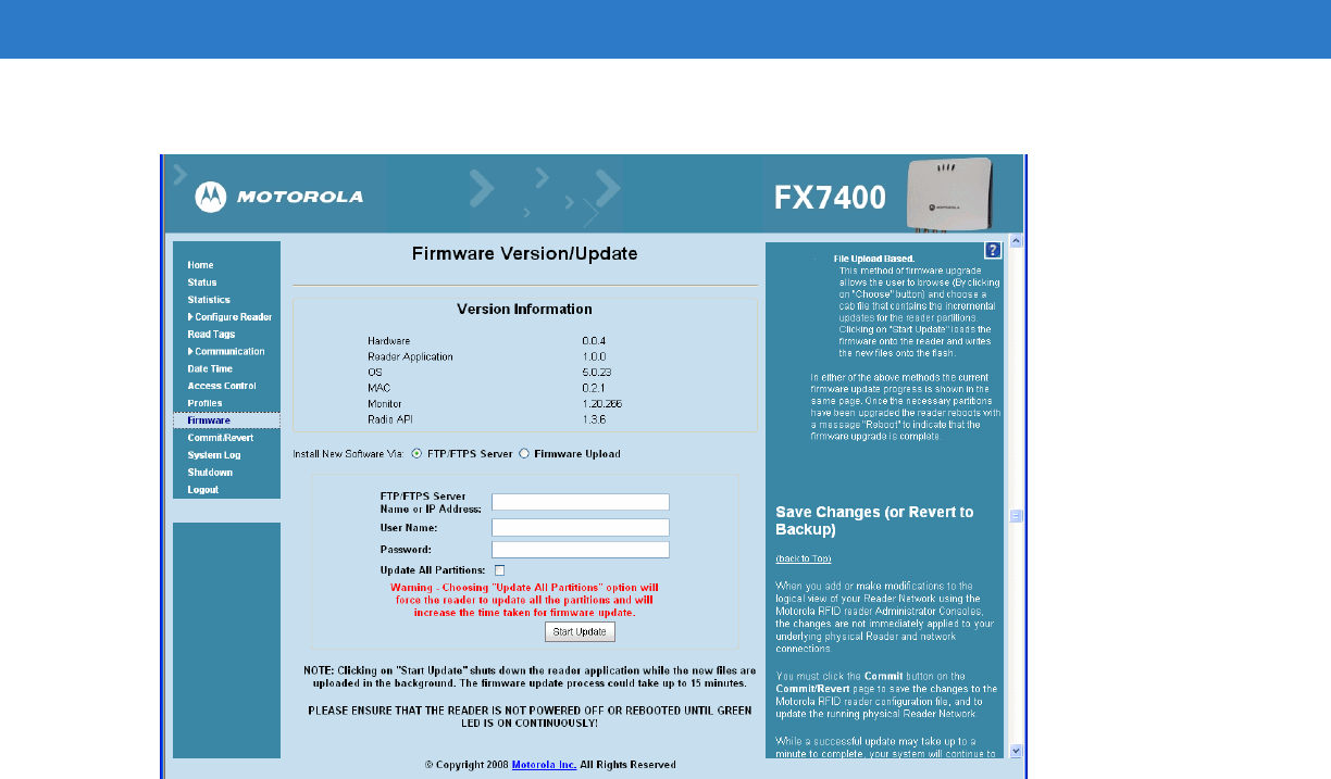
Administrator Console 4 - 29
Figure 4-27
FTP/FTPS Based Firmware Update Window
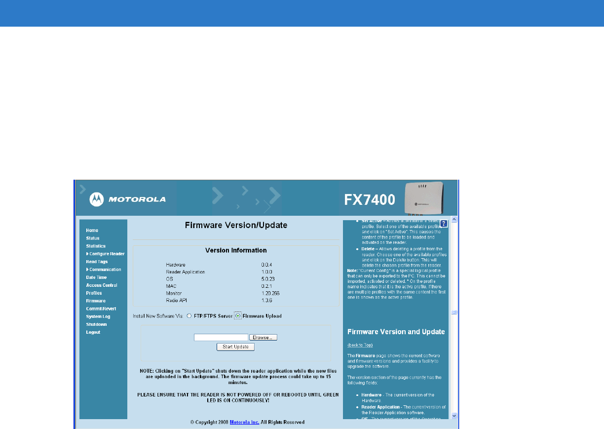
4 - 30 FX Series RFID Readers Integrator Guide
File Upload
•
Click Choose to browse to and choose a cab file containing the incremental updates for the reader partitions.
•
Click Start Update to load the firmware and write the new files onto the flash. The application shuts down and
the files listed in the Response.txt file are downloaded, validated, and programmed into flash. The reader
reboots. If all the files are not downloaded or are corrupted during the download, they are not programmed
into flash, and the old partitions remain.
Partition download and flash programming takes about 15 minutes. Do not reboot or power off the reader while the
green LED is blinking.
Figure 4-28
File Based Firmware Update Window
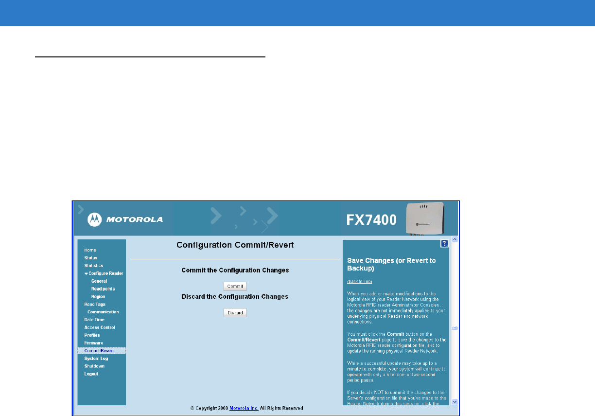
Administrator Console 4 - 31
Commit/Revert
Changes/modifications made to the logical view of the Reader Network using the Administrator Console are not
immediately applied the reader and network connections.
To apply reader configuration modifications, click Commit/Revert to save the changes and notify the reader to
update the configuration file. While a successful update can take several seconds, the system continues to operate
with only a one or two second period where no polling occurs.
From the Administrator Console:
1. Click Commit/Revert. The Commit/Revert window appears.
Figure 4-29
Commit/Discard Window
2. Click Commit to save a new configuration and apply changes to the reader configuration file, to save the
changes to the configuration file, and to update the reader/network.
A successful update can take up to a minute, however the system continues to operate with only a brief one or
two second pause.
Click Discard to discard changes made (during this session) to the reader configuration. This discards all
uncommitted changes.
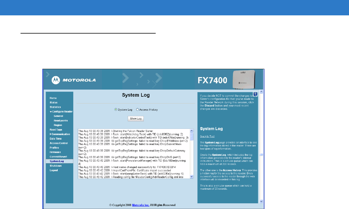
4 - 32 FX Series RFID Readers Integrator Guide
System Log
The System Log page provides an interface to view the reader log information. There are two types of log
information.
Figure 4-30
System Log Window
•
System Log - Includes the log information generated by the reader internal instructions. This is a circular
queue that holds a maximum of 200 records.
•
Access History - Provides a history log for reader access, including every successful access to the reader
through the web interface. This is also a circular queue which can hold a maximum of 20 records.
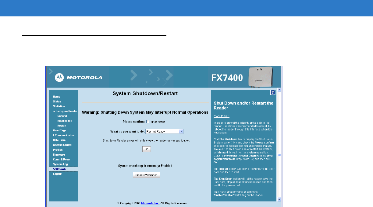
Administrator Console 4 - 33
Shutdown
To protect the integrity of the reader data, gracefully reboot the reader.
Figure 4-31
System Shutdown/Restart Window
From the Administrator Console:
1. Click the Shutdown link to display the Shut Down System page.
2. Check the Please Confirm check box to accept the system shut down and/or restart the system (this may
interrupt normal system operation).
3. Select either Restart or Shut Down from the What do you want to do drop-down list, and then click Go.
The Restart Reader option saves the user data and then restarts.
The Shut down Reader server option tells the reader to save the user data, stop all reader functions, and wait to
be powered off.
This page also provides an option to enable or disable the reader watchdog.

4 - 34 FX Series RFID Readers Integrator Guide

Chapter 5 Setup Examples
Introduction
The Setup Examples provide examples on how different types of reader configurations can be optimized.
Set-Up Examples
The Set-Up Examples are:
•
Point of Sale on page 5-2
•
Back Room Inventory Fill on page 5-3
•
Exit/Entry on page 5-4
•
Shelf/Tool Crib Cage on page 5-5
•
Transition/Impact Door on page 5-6
•
Back Room Receiving on page 5-7
•
Shelf/Tool Crib/Cage Inventory (stretched target) on page 5-8
NOTE The screens and windows are provided for illustration purposes only and may differ from actual screens.
The applications described may not be available on (or applicable to) all devices.
Procedures are not device specific and are intended to provide a functional overview.

5 - 2 FX Series RFID Readers Integrator Guide
Point of Sale
POS (Point of Sale) example prameters: Reader reads 10 different tags within 300 ms.
Can be single item, multiple items, or multiple tags. POS readers can be dense or separated/shielded area.
Indicate how POS readers can add writing. Indicate how reads can be triggered.
Installation
Identify the unique installation challenges for the POS example. The location of the reader and antennas (under
the read table) will be discussed and the procedures to optimize the tag reads.
•
Reference RFID Technology Overview on page 2-1 for RFID overview.
•Reference Introduction on page 3-1 for an installation overview.
•Reference Communications Connections on page 3-6 for standard communications connections overview
and provide the unique communications connections installation for a POS installation.
•Reference Reading Tags on page 3-7 for standard overview and provide the unique tag reading
installation requirements for a POS installation. Discuss antenna location one foot below the table (other
options?) discuss the Mobile Mark (BP6-915LP) antenna and the power setting of 20dBm.
Configuration and Optimization
Identify the unique configuration and optimization challenges for the POS example. Reference Introduction on
page 4-1 for a configuration overview.
•
Reference Reader Administrator Console on page 4-12 for standard procedures.
•
Reference Managing the FX Series RFID Readers on page 4-2 for standard reader management overview
and provide the unique reader management configuration optimization requirements for a POS installation.
•
Discuss optimization techniques for an under the table reader antenna.
Optimizing Reader Functions
Identify the unique function optimization challenges for the POS example.
For the setup illustrate:
•
Filtering (select statement)
•
Query tuning (Q, Session, Select bit)
•
Post read filtering
•
Writing, locking, killing
Troubleshooting
Identify the unique reader troubleshooting challenges for the POS example. Reference Introduction on page 6-1 for
a troubleshooting overview.
•
Reference Troubleshooting on page 6-1 for standard procedures and provide the unique reader
troubleshooting requirements for a POS installation.

Set-Up Examples 5 - 3
Back Room Inventory Fill
Back Room Inventory Fill example prameters: Reader reads 50-100 tags in 5 seconds at a distance of 2-6 feet.
Can be single item, multiple items, or multiple tags. Readers can be in a dense environment or separated /shielded
area. The opportunity to write is typically a lower priority then speed. Additional filtering may be needed. Indicate
how reads can be triggered. Indicate how to show direction with paired antennas.
Installation
Identify the unique installation challenges for the Back Room Inventory Fill example. The location of the reader and
antennas (under the read table) will be discussed and the procedures to optimize the tag reads.
•
Reference RFID Technology Overview on page 2-1 for RFID overview.
•Reference Introduction on page 3-1 for an basic installation overview.
•Reference Communications Connections on page 3-6 for standard communications connections overview
and provide the unique communications connections installation for a Back Room Inventory Fill
installation.
•Reference Reading Tags on page 3-7 for standard overview and provide the unique tag reading
installation requirements for a Back Room Inventory Fill installation. Discuss the 2 antenna locations one
foot below the table (other options?) and discuss the power setting of 30dBm.
•Discuss the antenna performance, ) 2 AN480 antennas were used.
Configuration and Optimization
Identify the unique configuration and optimization challenges for the Back Room Inventory Fill example. Reader
reader was optimized to read 50-100 tags in 5 seconds, within 2-6 feet. Reference Introduction on page 4-1 for a
configuration overview.
•
Reference Reader Administrator Console on page 4-12 for standard procedures.
•
Reference Managing the FX Series RFID Readers on page 4-2 for standard reader management overview
and provide the unique reader management configuration optimization requirements for a Back Room
Inventory Fill installation.
Optimizing Reader Functions
Identify the unique function optimization challenges for the Back Room Inventory Fill example.
For each setup illustrate:
•
Filtering (select statement)
•
Query tuning (Q, Session, Select bit)
•
Post read filtering
•
Writing, locking, killing
Troubleshooting
Identify the unique reader troubleshooting challenges for the Back Room Inventory Fill example. Reference
Introduction on page 6-1 for a troubleshooting overview.
•
Reference Troubleshooting on page 6-1 for standard procedures and provide the unique reader
troubleshooting requirements for a Back Room Inventory Fill installation.

5 - 4 FX Series RFID Readers Integrator Guide
Exit/Entry
Exit/Entry example prameters: The reader reads 1-20 tags, moving at 4-7 feet per second at distances between
2-8 feet and a read duration 7 seconds.
Filtering may be required depending on environment. Indicate how to adjust the power is (typically a tuning
parameter). This is a short range application, indicate how to optimize this application. Indicate how to write to tags
with the possibility of writing to the wrong tag.
Installation
Identify the unique installation challenges for the Exit/Entry example.The location of the reader and antennas will
be discussed and the procedures to optimize the tag reads.
•
Reference RFID Technology Overview on page 2-1 for RFID overview.
•Reference Introduction on page 3-1 for an installation overview.
•Reference Communications Connections on page 3-6 for standard communications connections overview
and provide the unique communications connections installation for a Exit/Entry installation.
•Reference Reading Tags on page 3-7 for standard overview and provide the unique tag reading
installation requirements for a Exit/Entry installation. 2 AN480 were used with power setting to 30dBm.
Configuration and Optimization
Identify the unique configuration and optimization challenges for the Exit/Entry example. Reference Introduction on
page 4-1 for a configuration overview.
•
Reference Reader Administrator Console on page 4-12 for standard procedures.
•
Reference Managing the FX Series RFID Readers on page 4-2 for standard reader management overview
and provide the unique reader management configuration optimization requirements for a Exit/Entry
installation.
Optimizing Reader Functions
Identify the unique function optimization challenges for the Exit/Entry example.
For each setup illustrate:
•
Filtering (select statement)
•
Query tuning (Q, Session, Select bit)
•
Post read filtering
•
Writing, locking, killing
Troubleshooting
Identify the unique reader troubleshooting challenges for the Exit/Entry example. Reference Introduction on page
6-1 for a troubleshooting overview.
•
Reference Troubleshooting on page 6-1 for standard procedures and provide the unique reader
troubleshooting requirements for a Exit/Entry installation.

Set-Up Examples 5 - 5
Shelf/Tool Crib Cage
Shelf/Tool Crib Cage example prameters: The reader reads 500 tags in 4 seconds at a distance of less than 12
feet.
Describe how to optimize filtering to avoid stray tags (outside the solution).
Installation
Identify the unique installation challenges for the Shelf/Tool Crib CageShelf/Tool Crib CageShelf/Tool Crib
CageShelf/Tool Crib CageShelf/Tool Crib Cage example.The location of the reader and antennas will be discussed
and the procedures to optimize the tag reads.
•
Reference RFID Technology Overview on page 2-1 for RFID overview.
•Reference Introduction on page 3-1 for an installation overview.
•Reference Communications Connections on page 3-6 for standard communications connections overview
and provide the unique communications connections installation for a Shelf/Tool Crib Cage installation.
•Reference Reading Tags on page 3-7 for standard overview and provide the unique tag reading
installation requirements for a Shelf/Tool Crib Cage installation.
•4 AN480 were used with power setting to 30dBm.
Configuration and Optimization
Identify the unique configuration and optimization challenges for the Shelf/Tool Crib Cage example. Reference
Introduction on page 4-1 for a configuration overview.
•
Reference Reader Administrator Console on page 4-12 for standard procedures.
•
Reference Managing the FX Series RFID Readers on page 4-2 for standard reader management overview
and provide the unique reader management configuration optimization requirements for a Shelf/Tool Crib
Cage installation.
Optimizing Reader Functions
Identify the unique function optimization challenges for the Shelf/Tool Crib Cage example.
For each setup illustrate:
•
Filtering (select statement)
•
Query tuning (Q, Session, Select bit)
•
Post read filtering
•
Writing, locking, killing
Troubleshooting
Identify the unique reader troubleshooting challenges for the Shelf/Tool Crib Cage example. Reference
Introduction on page 6-1 for a troubleshooting overview.
•
Reference Troubleshooting on page 6-1 for standard procedures and provide the unique reader
troubleshooting requirements for a Shelf/Tool Crib Cage installation.

5 - 6 FX Series RFID Readers Integrator Guide
Transition/Impact Door
Transition/Impact Door example prameters: Reader reads 200 tags moveing at 2~4 ft/sec for 7 seconds.
Can be single item, multiple items, or multiple tags (only interested in one). Readers can be in a dense
environment or separated /shielded area. The opportunity to write is typically a lower priority then speed. Additional
filtering may be needed. Indicate how reads can be triggered. Indicate how to show direction with paired antennas.
Installation
Identify the unique installation challenges for the Transition/Impact Door example.The location of the reader and
antennas will be discussed and the procedures to optimize the tag reads.
•
Reference RFID Technology Overview on page 2-1 for RFID overview.
•Reference Introduction on page 3-1 for an installation overview.
•Reference Communications Connections on page 3-6 for standard communications connections overview
and provide the unique communications connections installation for a Transition/Impact Door installation.
•Reference Reading Tags on page 3-7 for standard overview and provide the unique tag reading
installation requirements for a Transition/Impact Door installation.
•4 AN480 were used with a setting of 30dBm.
Configuration and Optimization
Identify the unique configuration and optimization challenges for the Transition/Impact Door example. Reference
Introduction on page 4-1 for a configuration overview.
•
Reference Reader Administrator Console on page 4-12 for standard procedures.
•
Reference Managing the FX Series RFID Readers on page 4-2 for standard reader management overview
and provide the unique reader management configuration optimization requirements for a Transition/Impact
Door installation.
Optimizing Reader Functions
Identify the unique function optimization challenges for the Transition/Impact Door example.
For each setup illustrate:
•
Filtering (select statement)
•
Query tuning (Q, Session, Select bit)
•
Post read filtering
•
Writing, locking, killing
Troubleshooting
Identify the unique reader troubleshooting challenges for the Transition/Impact Door example. Reference
Introduction on page 6-1 for a troubleshooting overview.
•
Reference Troubleshooting on page 6-1 for standard procedures and provide the unique reader
troubleshooting requirements for a Transition/Impact Door installation.

Set-Up Examples 5 - 7
Back Room Receiving
Back Room Receiving example prameters: The reader reads 500 tags in 5 seconds, within a distance of 10 feet.
Can be single item, multiple items, or multiple tags. Readers can be in a dense environment or separated /shielded
area. The opportunity to write is typically a lower priority then speed. Additional filtering may be needed. Indicate
how reads can be triggered. Indicate how to show direction with paired antennas.
Installation
Identify the unique installation challenges for the Back Room Receiving example. The location of the reader and
antennas (under the read table) will be discussed and the procedures to optimize the tag reads.
•
Reference RFID Technology Overview on page 2-1 for RFID overview.
•Reference Introduction on page 3-1 for an basic installation overview.
•Reference Communications Connections on page 3-6 for standard communications connections overview
and provide the unique communications connections installation for a Back Room Receiving installation.
•Reference Reading Tags on page 3-7 for standard overview and provide the unique tag reading
installation requirements for a Back Room Receiving installation. Discuss the 4 AN480 antenna locations
and the 30dBm power setting.
Configuration and Optimization
Identify the unique configuration and optimization challenges for the Back Room Receiving example. Reader
reader was optimized to read 50-100 tags in 5 seconds, within 2-6 feet. Reference Introduction on page 4-1 for a
configuration overview.
•
Reference Reader Administrator Console on page 4-12 for standard procedures.
•
Reference Managing the FX Series RFID Readers on page 4-2 for standard reader management overview
and provide the unique reader management configuration optimization requirements for a Back Room
Receiving installation.
Optimizing Reader Functions
Identify the unique function optimization challenges for the Back Room Receiving example.
For each setup illustrate:
•
Filtering (select statement)
•
Query tuning (Q, Session, Select bit)
•
Post read filtering
•
Writing, locking, killing
Troubleshooting
Identify the unique reader troubleshooting challenges for the Back Room Receiving example. Reference
Introduction on page 6-1 for a troubleshooting overview.
•
Reference Troubleshooting on page 6-1 for standard procedures and provide the unique reader
troubleshooting requirements for a Back Room Receiving installation.

5 - 8 FX Series RFID Readers Integrator Guide
Shelf/Tool Crib/Cage Inventory (stretched target)
Shelf/Tool Crib/Cage Inventory (stretched target) example prameters: The reader reads 500 tags in 5 seconds, at a
distance of 12 feet.
Can be single item, multiple items, or multiple tags (only interested in one). Readers can be in a dense
environment or separated /shielded area. Additional filtering may be needed. Indicate how reads can be triggered.
Indicate how to show direction with paired antennas.
Installation
Identify the unique installation challenges for the Shelf/Tool Crib/Cage Inventory (stretched target) example.The
location of the reader and antennas will be discussed and the procedures to optimize the tag reads.
•
Reference RFID Technology Overview on page 2-1 for RFID overview.
•Reference Introduction on page 3-1 for an installation overview.
•Reference Communications Connections on page 3-6 for standard communications connections overview
and provide the unique communications connections installation for a Shelf/Tool Crib/Cage Inventory
(stretched target) installation.
•Reference Reading Tags on page 3-7 for standard overview and provide the unique tag reading
installation requirements for a Shelf/Tool Crib/Cage Inventory (stretched target) installation.
Configuration and Optimization
Identify the unique configuration and optimization challenges for the Shelf/Tool Crib/Cage Inventory (stretched
target) example. Reference Introduction on page 4-1 for a configuration overview.
•
Reference Reader Administrator Console on page 4-12 for standard procedures.
•
Reference Managing the FX Series RFID Readers on page 4-2 for standard reader management overview
and provide the unique reader management configuration optimization requirements for a Shelf/Tool
Crib/Cage Inventory (stretched target) installation.
Optimizing Reader Functions
Identify the unique function optimization challenges for the Shelf/Tool Crib/Cage Inventory (stretched target)
example.
For each setup illustrate:
•
Filtering (select statement)
•
Query tuning (Q, Session, Select bit)
•
Post read filtering
•
Writing, locking, killing
Troubleshooting
Identify the unique reader troubleshooting challenges for the Shelf/Tool Crib/Cage Inventory (stretched target)
example. Reference Introduction on page 6-1 for a troubleshooting overview.
•
Reference Troubleshooting on page 6-1 for standard procedures and provide the unique reader
troubleshooting requirements for a Shelf/Tool Crib/Cage Inventory (stretched target) installation.

Set-Up Examples 5 - 9
Associating Tags (writing tags) with BC, Re-Commission
Associating Tags (writing tags) with BC, re-commission example prameters: The reader reads X tags in X seconds
at a distance of X feet.
Can be single item, multiple items, or multiple tags (only interested in one). Readers can be in a dense
environment or separated /shielded area. Additional filtering may be needed. Indicate how reads can be triggered.
Installation
Identify the unique installation challenges for the Associating Tags (writing tags) with BC, re-commission
example.The location of the reader and antennas will be discussed and the procedures to optimize the tag reads.
•
Reference RFID Technology Overview on page 2-1 for RFID overview.
•Reference Introduction on page 3-1 for an installation overview.
•Reference Communications Connections on page 3-6 for standard communications connections overview
and provide the unique communications connections installation for a Associating Tags (writing tags) with
BC, re-commission installation.
•Reference Reading Tags on page 3-7 for standard overview and provide the unique tag reading
installation requirements for a Associating Tags (writing tags) with BC, re-commission installation.
Configuration and Optimization
Identify the unique configuration and optimization challenges for the Associating Tags (writing tags) with BC,
re-commission example. Reference Introduction on page 4-1 for a configuration overview.
•
Reference Reader Administrator Console on page 4-12 for standard procedures.
•
Reference Managing the FX Series RFID Readers on page 4-2 for standard reader management overview
and provide the unique reader management configuration optimization requirements for a Associating Tags
(writing tags) with BC, re-commission installation.
Optimizing Reader Functions
Identify the unique function optimization challenges for the Associating Tags (writing tags) with BC, re-commission
example.
For each setup illustrate:
•
Filtering (select statement)
•
Query tuning (Q, Session, Select bit)
•
Post read filtering
•
Writing, locking, killing
Troubleshooting
Identify the unique reader troubleshooting challenges for the Associating Tags (writing tags) with BC,
re-commission example. Reference Introduction on page 6-1 for a troubleshooting overview.
•
Reference Troubleshooting on page 6-1 for standard procedures and provide the unique reader
troubleshooting requirements for a Associating Tags (writing tags) with BC, re-commission installation.

5 - 10 FX Series RFID Readers Integrator Guide
Chapter 6 Troubleshooting
Introduction
Table 6-1 on page 6-1 provides the FX Series troubleshooting information.
Troubleshooting
Table 6-1
Troubleshooting
Problem Possible Causes Possible Solutions
Reader error LED lights after the
reader has been in operation.
The CPU cannot
communicate.
Refer to the system log for error messages.
Reader error LED stays lit on power
up.
An error occurred during the
power up sequence.
Refer to the system log for error messages.
Cannot connect to the reader. User name and password is
unknown.
The default user name is
admin
and the default
password is
change
. To change the user name and
password. See
Communications Connections on
page 3-6
.
Reader is not reading tags. 1. The tag is out of its read
range
2. Antennas not connected
3. Tags are damaged
4. Tags are not EPCgen2
5. If reading with the
reader’s web page, Java 1.6
or later may not be installed
1. Move the tag into the read range. See
Read
Tags on page 4-18
.
2. Connect antennas
3. Confirm that tags are good
4. Confirm that tags are EPCgen2
5. Install Java 1.6. See
Java Upgrade Procedures
on page C-1
Cannot access the
Administrator
Console
.
The IP address is unknown. See
Communications Connections on page 3-6
to view the IP address.

6 - 2 FX Series RFID Readers Integrator Guide
Cannot log in to the terminal based
Administrator Console
.
The web based
Administrator Console
is in
use for that reader.
Log out of the web based console and restart the
terminal software to re-attempt log in.
Certain real time applications are no
longer functional.
The node address was
changed, the IP address, or
other reader configuration
parameter(s) using the
Administrator Console
, and
the application expects the
previous configuration.
Update the settings within the application. Refer to
the application manual.
The user closed the browser
without logging out of the
Administrator Console
, so
other applications cannot
connect to the reader.
Log out of the
Administrator Console
.
Cannot log into
Administrator
Console
.
User forgot the password. Press and hold the reset button for more than 5
seconds. This resets the reader configuration to
factory defaults, including the password.
Unable to add SNTP server, reader
returning error
SNTP server not reachable.
SNTP server name not
resolvable via DNS server.
DNS server not reachable.
Ensure SNTP server is reachable.
Ensure DNS server name is configured in TCP/IP
configuration.
Ensure DNS server is reachable.
Operation failed A user operation did not
complete, typically due to
invalid input.
Validate all the inputs and then retry the operation.
If it is not successful, see
Service Information on
page xi
.
Invalid User Name and/or
Password - Try again
The User Name and/or
password were not found in
the system, or do not match
the current user registry.
Accurately retype login information. If this is not
successful, contact Service (see
Service
Information on page xi
).
Session has Timed-out - Log in
again
The current session was
inactive beyond the time-out
period, so the system
automatically logged out.
Log in again. As a security precaution to protect
against unauthorized system access, always log
out of the system when finished.
User Name is not correct 1. The User Name does not
match the current user
registry (may be illegal
characters, too long, too
short, unknown or
duplicate.)
2. User forgot the user ID.
1. Accurately retype the User Name.
2. Contact Service (see
Service Information on
page xi
)
Table 6-1
Troubleshooting (Continued)
Problem Possible Causes Possible Solutions

Troubleshooting 6 - 3
The user name has already been
used.
The User Name is
duplicated when adding a
new user to the user
registry.
Retype a new User Name.
Not a legal IP address (1.0.0.0 -
255.255.255.255).
Cannot reach the specified IP
Address.
The SNMP Host Link is not valid.
The IP address entered is
either formatted inaccurately
or cannot be accessed
(pinged).
Accurately retype the IP address, and make sure
the Host device is connected and online. If this is
not successful, contact Service (see
Service
Information on page xi
)
Invalid network mask. The network mask entered
is not formatted correctly.
Confirm the correct network mask from network
administrator and type it in correctly.
Invalid SNMP version number. The version number for
SNMP protocol is not a
supported version.
Use version number 1 for SNMP version 1, and 2
for SNMP version 2c.
Invalid Description. The description contained
invalid characters (<,>,or').
Correct the description.
Invalid Password. 1. The password does not
match the current user
registry (may be illegal
characters, too long, or too
short.)
2. User forgot the password.
1. Accurately retype the password.
2. Contact Service (see
Service Information on
page xi
)
Name has already been used.
Serial Number has already been
used.
IP Address has already been used.
The Name, Serial Number,
or IP Address entered
already exists in the system.
Enter a unique value for the new Name, Serial
Number, or IP Address.
Select an item from the list. The system requires that an
item must be selected from
the list box before
continuing.
Select an item from the list box, and then continue.
Last command is still pending. Try
again later.
The system has not
completed processing the
previous command.
Wait a few moments for the previous command to
complete, before sending another command.
Another Administrator is currently
logged in. Try again later.
The system will not allow
more than one Administrator
to log in at a time.
Wait until the other Administrator logs out (or
times-out) before logging in.
Backup configuration file does not
exist.
The system cannot revert to
a backup of the current
configuration unless a
backup file exists.
Commit the new configuration to create a backup
file.
Table 6-1
Troubleshooting (Continued)
Problem Possible Causes Possible Solutions

6 - 4 FX Series RFID Readers Integrator Guide
Failed to confirm the new
Password.
The system requires that the
password must be
identically two times.
Accurately retype the password twice.
Network configuration change(s)
have not been saved.
The user has requested to
log out prior to
committing/reverting the
changes made during their
session.
Select one of the Commit/Revert options.
New Password is the same as the
old one.
The system requires the
entry of a new password
(that is different from the
existing password) during
the
Change Password
operation.
enter a new password that is different from the
existing password.
Old Password is not correct. The system requires the
entry of the existing
password during the
Change Password
operation.
Accurately retype the password the existing
password.
Commit Finished - New
Configuration Changes have been
accepted.
Discard Accepted - Configuration
reverted to last committed version.
Operation was Successful
Requested function was
performed.
No action required. The system is reporting that
the request was accepted.
Unspecified error occurred - code:
####
A specific error message is
missing for the given status
code.
Note the code number, and contact Motorola
Enterprise Mobility support. See
Service
Information on page xi
.
The requested page was not found.
Internal Web Server Error.
The system experienced an
internal web server error.
Contact Motorola Enterprise Mobility support. See
Service Information on page xi
Request method was NULL.
No query string was provided.
The system does not permit
a proxy program to be
executed from the command
line rather than the web
server.
No action required. The system is reporting that
this action is not permitted.
Content length is unknown. The system cannot accept
an incorrectly formatted
HTTP POST request (from
an unsupported Browser
application).
Use a GET request instead, or update the
software.
Couldn't read complete post
message.
The system stopped a
POST operation before
completion.
Retry the operation, and allow it to complete.
Table 6-1
Troubleshooting (Continued)
Problem Possible Causes Possible Solutions

Troubleshooting 6 - 5
Unhandled reply type. The system generated an
unexpected value.
Contact Motorola Enterprise Mobility support. See
Service Information on page xi
.
Failed to open port.
Failed to connect.
Failed to transmit.
Failed to receive.
Error during Receive of Command.
Error during receive of
command.
Contact Motorola Enterprise Mobility support. See
Service Information on page xi
.
Invalid Device Address. The device address info
(parent) is invalid, missing,
or formatted inaccurately.
Contact Motorola Enterprise Mobility support. See
Service Information on page xi
.
Command parsing state error.
Missing argument for the command.
Command internal type cast error.
Missing operator.
Unknown operator.
A command has been
formatted inaccurately.
Contact Motorola Enterprise Mobility support. See
Service Information on page xi
.
The action must be confirmed. The requested action must
be confirmed by user before
it is actually executed.
Select the confirmation option when issue this
request.
Table 6-1
Troubleshooting (Continued)
Problem Possible Causes Possible Solutions
NOTE If problems still occur, contact the distributor or call the local contact. See page xi for contact information.

6 - 6 FX Series RFID Readers Integrator Guide

Appendix A Technical Specifications
Technical Specifications
The following tables summarize the RFID reader intended operating environment and technical hardware
specifications.
Table A-1
Technical Specifications
Item FX
Physical and Environmental Characteristics
Dimensions 7.7 in. L x 5.9 in. W x 1.7 in. D
19.56 cm L x 14.99 cm W x 4.32 cm D
Mounting Dimensions
(Mounting Holes)
2 holes required, center to center 4.192 inches
Weight 1.8 lbs (kg)
Base Material Die cast aluminum, sheet metal and plastic.
LEDs Multi-color LEDs: Power, Activity, Status and Applications
FX Environmental Specifications
Operational Temperature 14° to +122° F/-10° to +50° C
Storage Temperature -40° to +158° F/-40° to +70° C
Humidity 5 to 85% non-condensing
Vibration Vibration Operational: 5.5 Grms, 0.02G2/Hz Random 20 Hz to 1000 Hz rolling off at
-6 dB/octave to 2000 Hz for 1 hour per axis in all three axes.
Connectivity
Communications 10/100 BaseT Ethernet (RJ45) w/ POE support
USB Client (USB Type B)
General Purpose I/O 2 inputs, 2 outputs, optically isolated (Terminal Block)
Power +24Vdc or POE (IEEE 802.3af)

A - 2 FX Series RFID Readers Integrator Guide
Antenna Ports FX 7400-4: 4 mono-static ports
(Reverse Polarity TNC)
FX 7400-2: 2 mono-static ports
(Reverse Polarity TNC)
Compliance Information
Safety cUL 60950-01, UL 2043, IEC 60950-1, EN 60950-1
RF/EMI/EMC FCC Part 15, RSS 210, EN 302 208, ICES-003
Class B, EN 301 489-1/3
SAR/MPE FCC 47CFR2:OET Bulletin 65; EN 50364
Other ROHS, WEEE
Antenna Parameters FX Series US EU
Max Conducted RF Power + 30dBm +29.2dBm
Max Antenna Gain Allowed (including cable loss) + 6dBiL + 6dBiL
Max Radiated Power Allowed 4W EIRP 2W ERP
Maximum Beam Width N/A Per EN 302 208
Hardware/OS and Firmware Management
Memory Flash 64 MB; DRAM 64 MB
Operating System Microsoft Windows CE 5.0
Firmware Upgrade Web based and remote firmware upgrade capabilities
Management Protocols RM 1.0.1 (with XML over HTTP/HTTPS and
SNMP binding)
Network Services DHCP, HTTPS, FTPS, SSH, HTTP, FTP, Telnet,
SNMP and NTP
Air Protocols ISO 18000-6C (EPC Class 1 Gen 2)
Frequency (UHF Band) 902 MHz to 928 MHz, 865 MHz to 868 MHz
Power Output +15dBm to +30dBm
IP addressing Static and Dynamic
Host Interface Protocol LLRP
API Support .NET, C and JAVA
Warranty
The FX7400-4 and FX7400-2 are warranted against defects in workmanship and materials for a period of one year
(12 months) from date of shipment, provided the product remains unmodified and is operated under normal and
proper conditions.
For the complete Motorola hardware product warranty statement, go to:
http://www.motorola.com/enterprisemobility/warranty
Table A-1
Technical Specifications (Continued)
Item FX
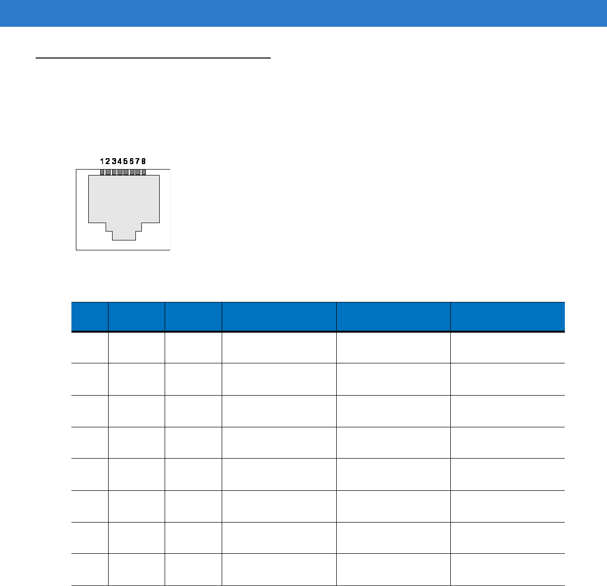
Technical Specifications A - 3
Cable Pinouts
10/100bT Ethernet / POE Connector
The 10/100BT Ethernet / POE connector is an RJ45 receptacle. This port must comply with 802.3af specification
for Powered Devices.
Figure A-1
Ethernet Connections
Table A-2
10/100bT Ethernet / POE Connector Pinout
Pin Pin Name Direction Description POE Mode A
Function POE Mode B
Function
Pin 1 TX-P O TX Data Positive Rail Positive Vport,
Negative Vport
Pin 2 TX-N O TX Data Negative Rail Positive Vport,
Negative Vport
Pin 3 RX-P I RX Data Positive Rail Positive Vport,
Negative Vport
Pin 4 NC - No Connect Positive Vport,
Negative Vport
Pin 5 NC - No Connect Positive Vport,
Negative Vport
Pin 6 RX_N I RX Data Positive Rail Positive Vport,
Negative Vport
Pin 7 NC - No Connect Positive Vport,
Negative Vport
Pin 8 NC - No Connect Positive Vport,
Negative Vport
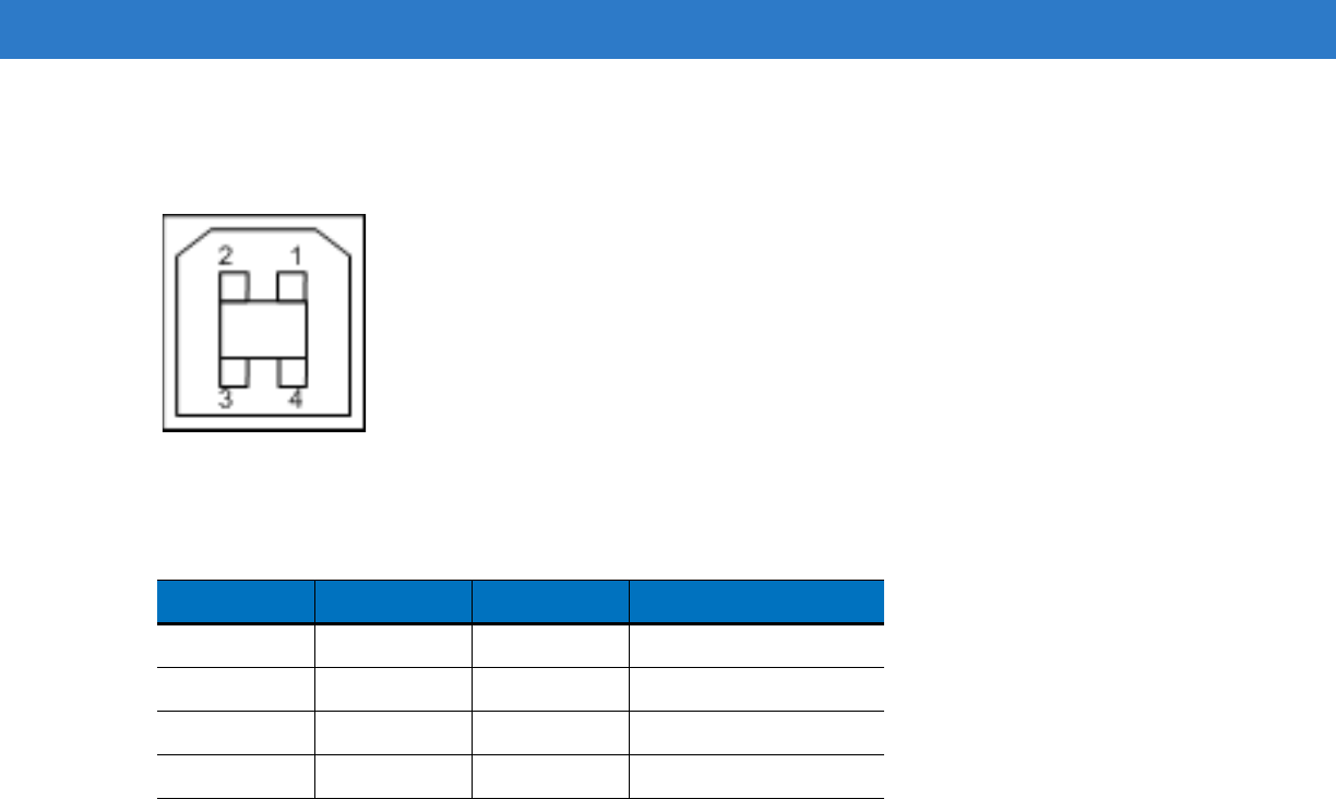
A - 4 FX Series RFID Readers Integrator Guide
USB Client Connector
The USB Client port is supplied on a USB Type B connector.
Figure A-2
USB Client Connector
Table A-3
USB Client Port Connector Pinout
Pin Pin Name Direction Description
Pin 1 5.0V_USB 1 5.0V USB Power Rail
Pin 2 USB_DN I/O Data Negative Rail
Pin 3 USB_DP I/O Data Positive Rail
Pin 4 GND - Ground
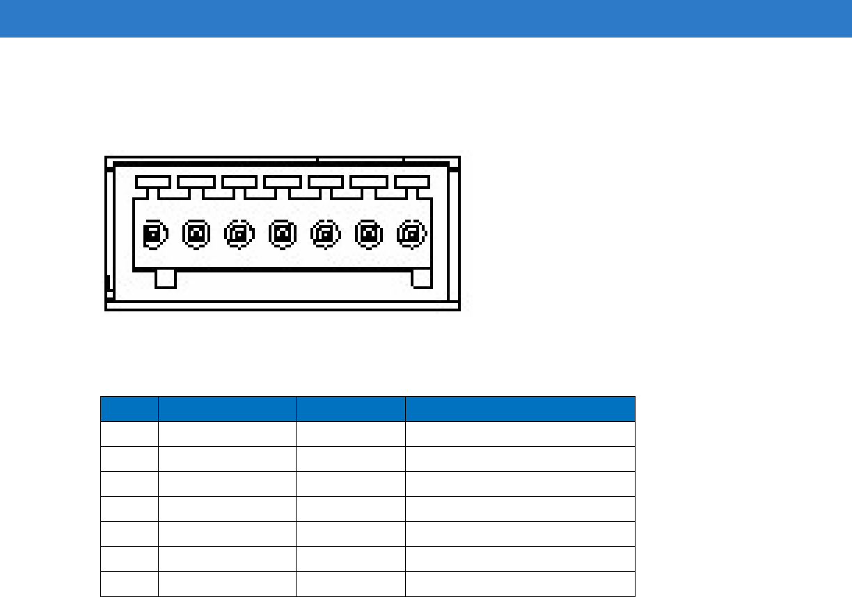
Technical Specifications A - 5
GPIO Port Connections
These are plug terminal block types, allowing connecting and disconnecting individual wires independently.
Separate connectors are used for inputs and outputs. See Table A-4 for pin descriptions.
Figure A-3
FX Series RFID Reader GPIO Connection
Table A-4
GPIO Pin Outs
Pin # Pin Name Direction Description
1 +24V DC Power Input Supplies +24V DC at up to 1 Amp
2 GP output #1 Input Signal for GP output #1
3 GP output #2 Input Signal for GP output #2
4 GP input #1 Output Signal for GP input #1
5 GND Output Ground connection
6 GP input #2 Output Signal for GP input #2
7 GND Output Ground connection
1 2 3 4 5 6 7

A - 6 FX Series RFID Readers Integrator Guide
Third Party Software
The FX Series readers use third party open source and licensed software:
•
SSH: Open SSH for Windows CE is part of the Microsoft open source project hosting web site Codeplex.com.
For more details about the Open SSH for Windows CE visit http://www.codeplex.com/CESSH.
•
FTPS Server and Client: Motorola customized the open source project IndiFTPD for Windows CE and ported
it to FX Series readers. For more details about IndiFTPD projects visit
http://sourceforge.net/projects/indiftpd/.
•
Openssl : The OpenSSL Project is a collaborative effort to develop a robust, commercial-grade, full-featured,
and Open Source toolkit implementing the Secure Sockets Layer (SSL v2/v3) and Transport Layer Security
(TLS v1) protocols as well as a full-strength general purpose cryptography library. The project is managed by
a worldwide community of volunteers that use the Internet to communicate, plan, and develop the OpenSSL
toolkit and its related documentation. Open source URL is http://openssl.org.
•
FTPS Client: Download from http://bsdftpd-ssl.sc.ru/download.html. License details are available in the
attached COPYRIGHT file.
•
Polaris Network LLRP Tester: Polaris Networks, Inc. non-open source tool. Purchased license for LLRP
Protocol conformance testing.
•
LLRP Toolkit: Download from http://sourceforge.net/projects/llrp-toolkit/. Open Source, Apache license v2.
The license is available at http://www.apache.org/licenses/LICENSE-2.0.
•
Win32 pThreads: Download from http://sourceware.org/pthreads-win32/. Open Source, GNU Lesser General
Public License.
•
Code Synthesis XSD/e: Download from http://www.codesynthesis.com/products/xsde/download.xhtml. Open
Source, GNU General Public License 2. Visit http://www.codesynthesis.com/products/xsde/license.xhtml.
•
Yahoo User Interface (YUI): Download from http://developer.yahoo.com/yui/. Open source, BSD license. Visit
http://developer.yahoo.com/yui/license.html.
•
Net-SNMP: Download from http://www.net-snmp.org/. Open source, BSP like license (CMU/UCD license).
See http://www.net-snmp.org/about/license.html.
•
LibXML2: Parent site: http://xmlsoft.org, downloaded from ftp://xmlsoft.org/libxml2/. Open source, MIT
License. Visit http://www.opensource.org/licenses/mit-license.html.
•
Intel R2000 firmware: Delivered by Intel support. Refer to Intel R2000 SW License.pdf.
•
DPWSCore: Parent site: https://forge.soa4d.org/projects/dpwscore/. Open source Lesser GNU Public
License.
•
gSOAP: GeniviaGSoapLicense.pdf and MotorolaPO-NP4702753.pdf. Site:
http://www.cs.fsu.edu/~engelen/soap.html. Software development Site License.

Appendix B Firmware Upgrade Procedures
Introduction
This appendix provides the reader firmware upgrade procedure using the web-based Administrative Console.
There are two methods to update reader firmware:
•
Update Method 1, Use a LAN on page B-3 - the preferred method when there are a number of readers
connected to a LAN.
•
Update Method 2, Direct Connect Over the Ethernet Port on page B-5 - the preferred method when updating
a single reader using an Ethernet crossover cable.
Each of the following types of firmware performs unique changes to the current settings and can be upgraded
independently. Available firmware includes:
•
Monitor Version
•
OS Version
•
Application Server Version
•
MAC Radio Firmware Version
•
Radio API Version
Prerequisites
The following items are required to perform the update:
•
Reader with power supply
•
Laptop (or other host computer)
•
If using the LAN Update procedure, a Cat5 ethernet cable is required
•
If using the Direct-Connect update procedure a Cat5 Crossover cable is required
•
An ftp server on the host computer

B - 2 FX Series RFID Readers Integrator Guide
•
Current firmware file examples:
•OSUpdFalcon.exe
•response.txt
•FlashUpdateUtility.dll
•FalRDataXXX.hex (Data partition, XXX is a filename variable)
•FalRConfigXXX.hex (Reader Config, XXX is a filename variable)
•FalPlatXXX.hex (Platform partition, XXX is a filename variable)
•FalParTblXXX.hex (Partition table, XXX is a filename variable)
•FalOSUnrelXXXXX.hex (OS, XXXXX is a filename variable)
•FalMonXXXX.hex (Monitor, XXXX is a filename variable)
•FalDataXXX.hex (Data partition, XXX is a filename variable)
•FalConfAreaXXX.hex (Reader Config, XXX is a filename variable)
•FalBkupOSXXXXX.hex (OS, XXXXX is a filename variable)
•FalAppXXX.hex (Application, XXX is a filename variable)
Refer to the release notes to determine which files were updated; not all of the files are updated in every release.
There is no specific order necessary when installing these files.
Auto Recovery
The Auto Recovery feature allows the reader to recover flash images that are corrupt due to a power outage during
software upgrade. If a firmware upgrade (over LAN) fails (e.g., due to a power outage), on the next reboot the
reader retries the update from the same remote server. If reader cannot complete the update, a recovery web page
appears when accessing the reader management interface via a web browser. To reattempt upgrade, enter the
FTP server path and credentials.
Update Phases
The firmware update takes place in two phases:
Phase 1 - The reader application retrieves the Response.txt, osupdFX.exe, and FlashUpdateUtility.dll files from the
ftp server.
Phase 2 - The reader application shuts down and the OsUpdate starts. The files referenced in the Response.txt file
are retrieved from the ftp server.
A typical entry in the Response.txt is:
;Platform partition version 1.2.7
-t4 -FXc42PlatH127.hex -s2679149
NOTE The Application Server, Radio API, and MAC firmware code all reside in the Platform partition.
NOTE The recovery console supports only the FTP mode update, and does not support secure FTP (FTP over
TLS explicit) or CAB file update.

Firmware Upgrade Procedures B - 3
The -t parameter is the file type, -f is the name of the file, and -s the size. Ensure the file size is correct.
";" comments out the rest of the line.
Update Method 1, Use a LAN
This is the preferred method, since readers are typically on a LAN and the update does not require existing
connections to change.
1. Create a folder on a local ftp server and name it: \FXUPDT\ReleaseXXX.
2. Download the firmware files from http://www.support.symbol.com into this folder and unzip the files if they are
zipped.
3. Ensure that the readers can be pinged from the host computer. If they cannot, consult with the network
administrator.
4. On the reader to update, access the web based Administrator Console:
a. Open a browser and type the IP address of the reader to update (format example: http://157.235.88.147).
The Reader Administrator Console login screen appears. See Connect to the Reader on page 4-3.
b. Enter the user name and password. If this is the first time accessing the console, a prompt appears for a
user name and password update. The default settings are:
Username: admin
Password: change
The Administrator Console Main Menu appears. See Figure 4-14 on page 4-12.
5. From the Console Main Menu select Scan Control the Reader Scan Control.
6. Click the Enable/Disable Polling button to set Disable Polling. The button reads Enable Polling when polling is
disabled.
7. Select Maintenance. The Reader Maintenance Console appears. See Figure 4-1 on page 4-2. [refers to
Maintenance chapter that was removed; remove step??]
8. Select Version. The Version Control screen appears with the current version information. See Figure 4-14 on
page 4-22. [refers to Maintenance chapter that was removed; remove step??]
9. To upgrade the firmware:
a. Ensure the ftp server is running on the host computer.
b. Ensure the TFTP server is running on the host computer, and that the file path is the same as when
logging on using the FTP server.
c. On the Version Control screen, enter in the following information:
For the ftp Server link, enter ftp://<ip address of host computer>/filepath (format example:
ftp://192.168.1.3// FX UPDT/ReleaseXXX). Be sure to enter an IP address; entering the host name does
not work.
Enter the ftp server user name.
Enter the ftp server password.
NOTE If using the default host computer ftp server, the system user name and password may be required
(consult the system administrator).

B - 4 FX Series RFID Readers Integrator Guide
d. Click Start Update to start the update. The reader indicates that it is going to shutdown.
e. The green LED on the reader flashes during the update. The reader application software first downloads
osupFX.exe, FlashUpdateUtility.dll, and Response.txt files, starts running Osupdate, and shuts down.
Osupdate then downloads all the files specified in the Response.txt file into RAM, and if successful writes
the files to Flash. If the ftp is not successful, no files are written to Flash.
f. The update can take up to 15 minutes. Do not remove power to the reader or reboot the reader during the
update.
g. The reader reboots when the update completes.
h. If the reader is set up with a static IP address, it restores the static IP address and reboots again.
i. The reader may reboot a third time if the FPGA version has changed.
10. Log onto the web console, access the Version Control screen, and verify the new upgrade version is running.
NOTE During the FPGA update, all the LEDs turn off for about 90 seconds.
If there is a power outage during the upgrade, when the power comes back on, the reader Monitor
program retrieves all the files using the TFTP server and saves them to Flash.
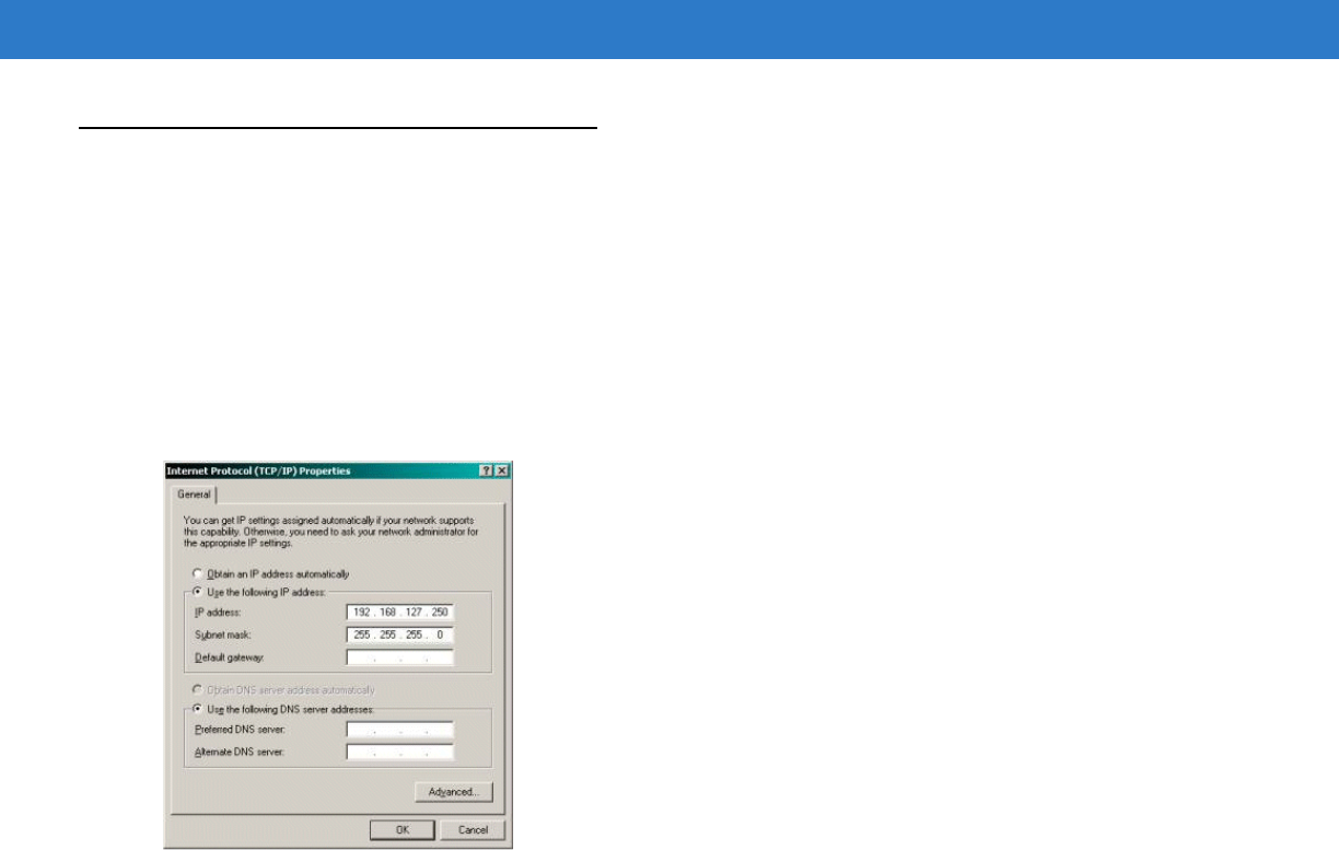
Firmware Upgrade Procedures B - 5
Update Method 2, Direct Connect Over the Ethernet Port
Use this method to update a reader that is not on a LAN.
1. Use the serial Administrator Console to disable DHCP on the reader, and configure it for a static IP address
(192.168.1.3).
2. Configure the host computer to reside on the same subnet as the reader:
a. Open Network Connections and locate the connection to use to connect to the reader.
b. Open the TCP/IP Connection Properties window. Modify this to use a static IP address on the same subnet
as the reader (192.168.1.5). Click OK.
Figure B-1
TCP/IP Connection Properties Screen
3. Connect the Cat5 crossover cable from the host computer to the reader.
4. On the reader, access the web-based Administrator Console:
a. Open a browser and type http://192.168.1.3 (or the IP address of the reader to upgrade, if it is not the
default address above). The Reader Administrator Console login screen appears. See Connect to the
Reader on page 4-3.
b. Enter the user name and password. If this is the first time accessing the console, a prompt appears for a
user name and password update. The default settings are:
Username: admin
Password: change
The Console Main Menu appears. See Figure 4-14 on page 4-12.
5. From the Console Main Menu select Scan Control. The Reader Scan Control screen appears.
6. Click the Enable/Disable Polling button to set to Disable Polling. The button reads Enable Polling if polling is
disabled.
7. Select Maintenance. The Reader Maintenance Console appears. See Figure 4-1 on page 4-2. [refers to
Maintenance chapter that was removed; remove step??]
8. Select Version. The Version Control window displays the current version information. See Figure 4-14 on page
4-22. [refers to Maintenance chapter that was removed; remove step??]

B - 6 FX Series RFID Readers Integrator Guide
9. Upgrade the firmware:
a. Ensure that an ftp server is running on the host computer.
Do not change any other default setting (the necessary defaults should already be in
C:/FXUPDT/ReleaseXXX).
b. On the Version Control screen, enter in the following information:
For the ftp Server link, enter ftp://<ip address of host computer>/filepath (ftp://192.168.1.5// FXUPDT/
ReleaseXXX). Be sure to enter an IP address; entering the host name does not work.
Enter the ftp server user name.
Enter the ftp server password.
c. Click Start Update. See Figure 4-14 on page 4-22. The reader indicates that it is shutting down. [refers to
Maintenance chapter that was removed; remove step??]
d. The green LED on the reader flashes during the update. The reader application software first downloads
osupFX.exe, FlashUpdateUtility.dll, and Response.txt files, starts running Osupdate, and shuts down.
Osupdate then downloads all files specified in the Response.txt file into RAM, and if successful writes the
files to Flash. If the ftp is not successful, no files are written to Flash.
e. This update can take up to 15 minutes. Do not remove power to the reader or reboot the reader during the
update.
f. The reader reboots when the update completes.
10. Log onto the web console and access the Version Control window. Verify the new upgrade version is running.
NOTE Refer to the release notes to determine which files changed; Not all of the files are updated in every
release. There is no specific order necessary when installing these files.
NOTE If using the default host computer ftp server, the system user name and password may be required
(consult the System Administrator).
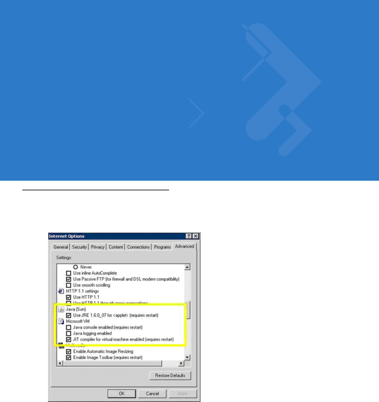
Appendix C Java Upgrade Procedures
Introduction
The FX Series reader browser interface requires Java1.6 or later. To confirm the Java version in the Internet
Explorer web browser, go to Tools > Internet Options > Advanced tab:
Figure C-1
Java Version Window
Install Java 1.6 or later if the virtual machine configuration entries are missing, or if an earlier version is installed.
Download JVM from http://www.java.com/en/download/manual.jsp

C - 2 FX Series RFID Readers Integrator Guide
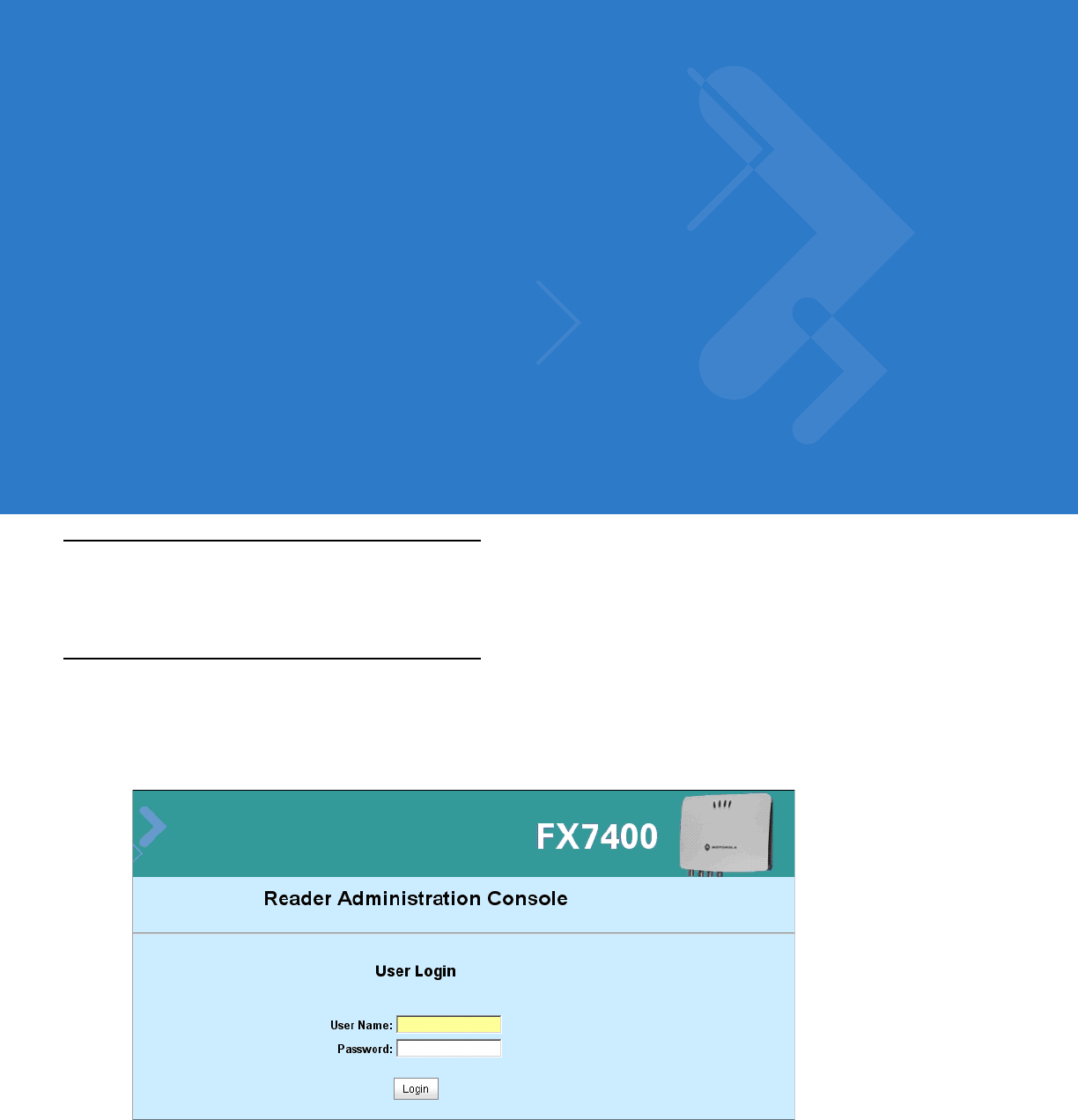
Appendix D Static IP Configuration
Introduction
This appendix describes three methods of setting the static IP address on an FX7400 RFID Reader.
DHCP Network is Available - Set the Static IP Using the Web Console
1. Browse the device using the host name, e.g., FX7400CD3B1E.
2. Log onto the device.
Figure D-1
Reader Administration Console Login Window
3. Click Communication, then click Network.
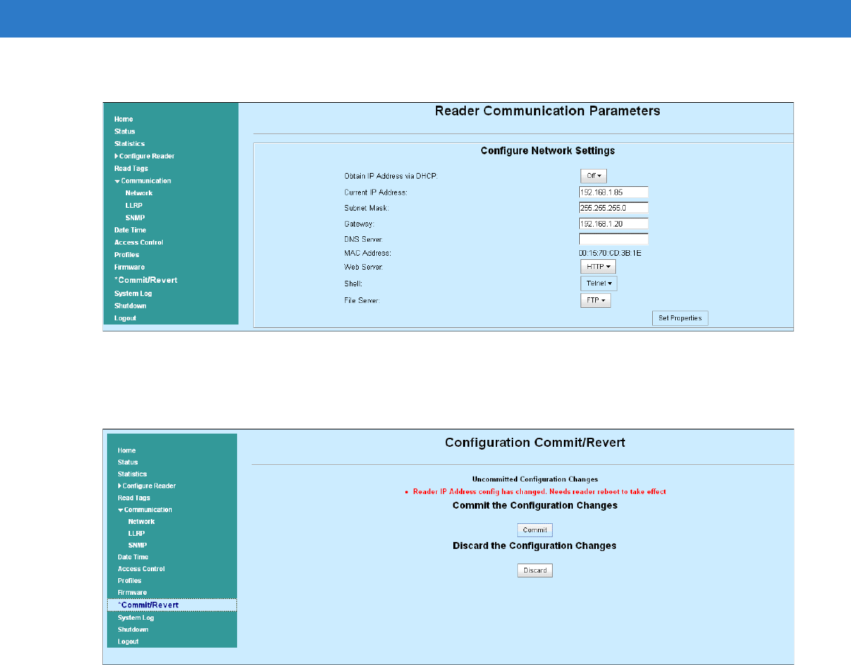
D - 2 FX Series RFID Readers Integrator Guide
4. Set Obtain IP Address via DHCP to Off and enter all required information.
Figure D-2
Reader Communication Parameters Window
5. Click Set Properties. You can set a static IP that doesn't belong to this DHCP network.
6. Click Commit/Revert, then click the Commit button.
Figure D-3
Commit/Revert Window
7. The message Reader IP Address config has changed. Needs reader reboot to take effect appears. Reset the
device and use the reader with the static IP network.
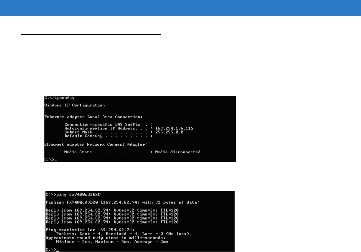
Static IP Configuration D - 3
DHCP Network Not Available - Set the Static IP Using the Web Console
1. Connect the device and a PC running Windows XP to the same network that doesn't have DHCP server, or
connect the device directly to the PC.
2. Ensure both the device and PC Ethernet jack use at least one LED to indicate network connection detect.
3. If the PC uses an assigned static IP, update it to use DHCP. The PC obtains an IP that starts with 169.
Figure D-4
Obtain IP Address
4. When possible, ping the hostname of the device.
Figure D-5
Ping the Hostname
5. Browse the device with host name, e.g., FX7400CD3B1E.
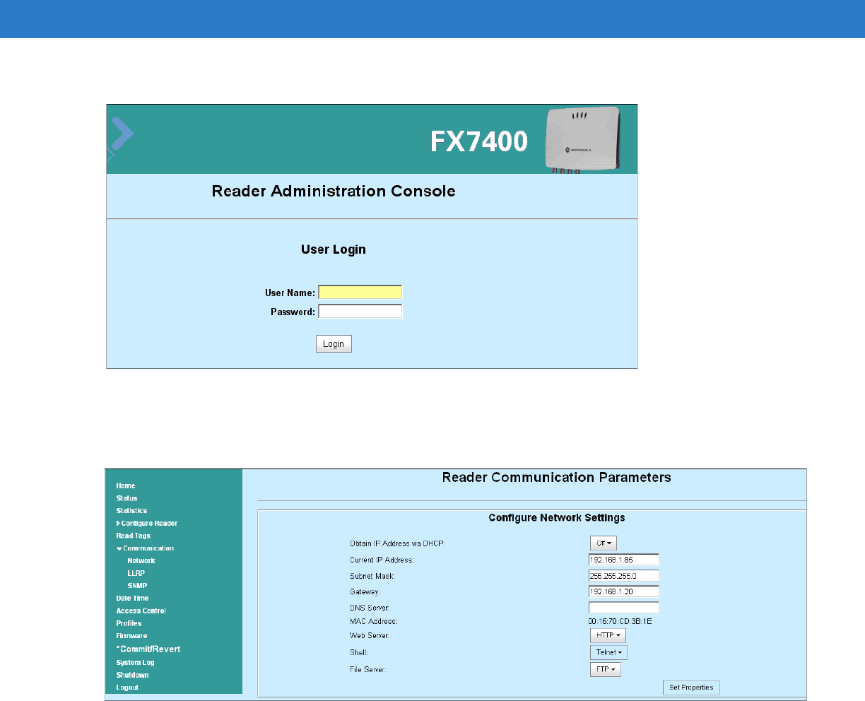
D - 4 FX Series RFID Readers Integrator Guide
6. Log onto the device.
Figure D-6
Reader Administration Console Login Window
7. Click Communication, then click Network.
8. Set Obtain IP Address via DHCP to Off and enter all required information.
Figure D-7
Reader Communication Parameters Window
9. Click Set Properties.
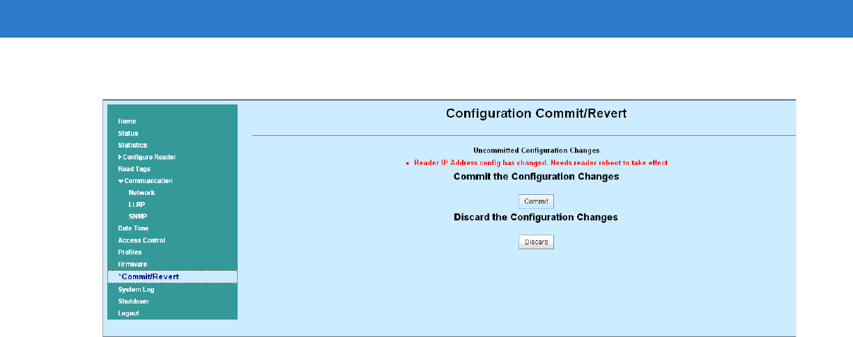
Static IP Configuration D - 5
10. Click Commit/Revert, then click the Commit button.
Figure D-8
Commit/Revert Window
11. The message Reader IP Address config has changed. Needs reader reboot to take effect appears. Reset the
device and use the reader with the static IP network.
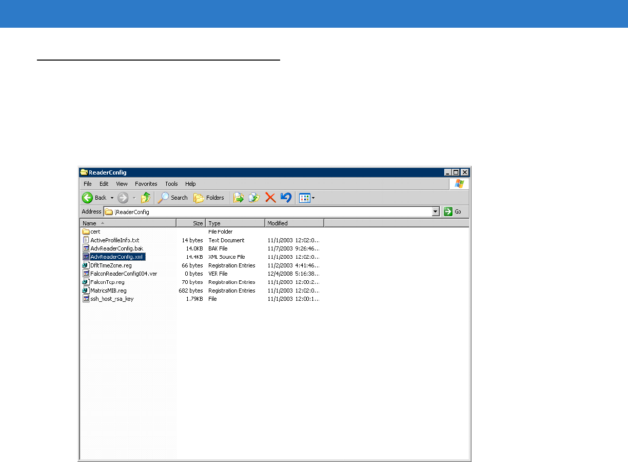
D - 6 FX Series RFID Readers Integrator Guide
DHCP Network Not Available - Edit Configuration Files to Set the Static IP
Use this option to configure a static IP on the reader regardless of the host network settings:
1. Establish an ActiveSync connection over USB to the reader.
2. Browse to the \ReaderConfig directory on the reader. Copy AdvReaderConfig.xml from \ReaderConfig to a local
folder.
Figure D-9
Copy AdvReaderConfig.xml
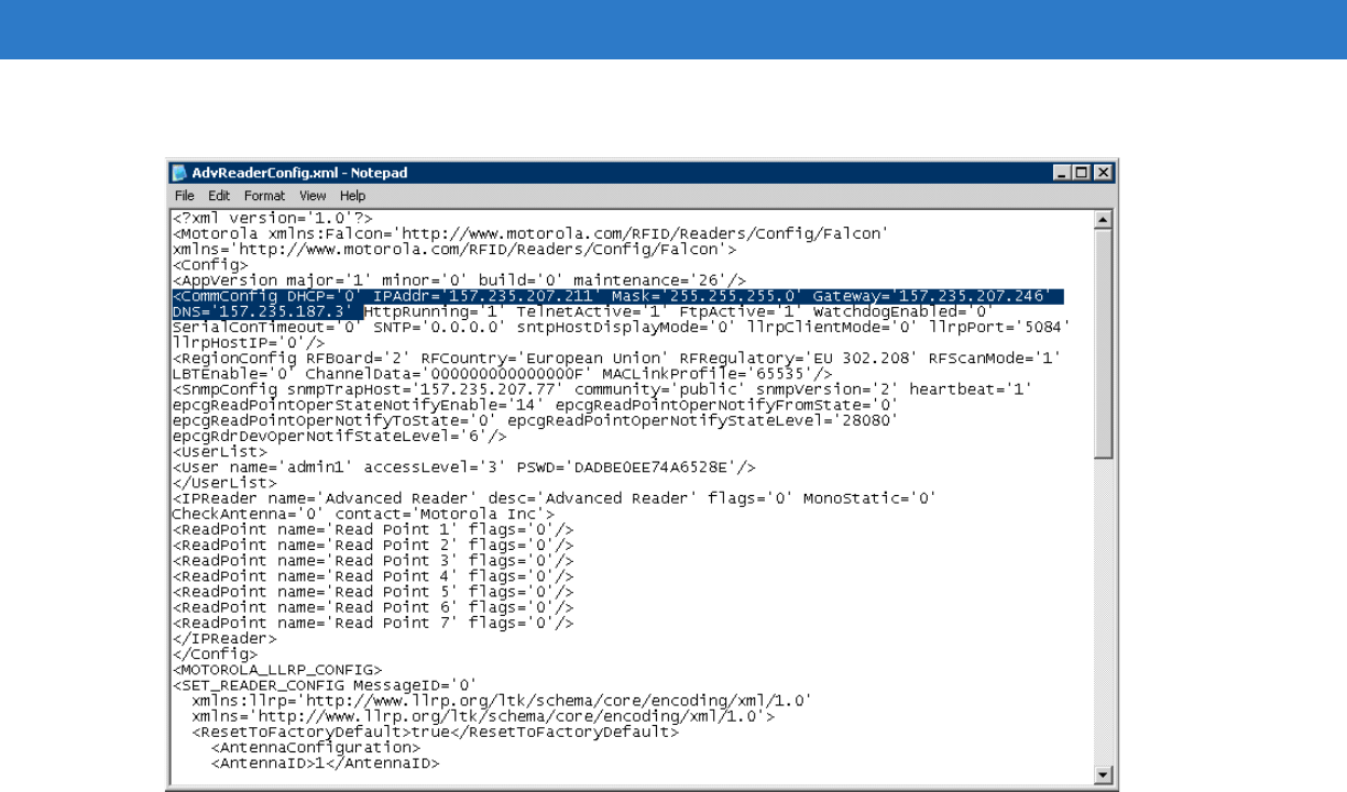
Static IP Configuration D - 7
3. Open AdvReaderConfig.xml in any text editor.
Figure D-10
Copy AdvReaderConfig.xml
4. Change DHCP to 0, and set IPAddr, Mask, and optionally Gateway and DNS IP addresses to desired values.
5. Save the edited file locally.
6. Copy and replace the edited AdvReaderConfig.xml file in the \ReaderConfig directory.
7. Reset the reader twice as follows:
a. Insert a paper clip into the reset hole for less than two seconds, or repower the unit. The Boot LED turns
red, then remains amber during initialization. When the reader has initialized, the LED turns green.
b. After the reader initializes and the LED turns green, reset the reader again as in Step a. When the Boot
LED is green, reader is ready and accessible using the configured IP.

D - 8 FX Series RFID Readers Integrator Guide

Index
Numerics
10/100BaseT Ethernet . . . . . . . . . . . . . . . . . . . . .1-2, 2-5
2-port reader . . . . . . . . . . . . . . . . . . . . . . . . . . . . . . . 2-4
4-port reader . . . . . . . . . . . . . . . . . . . . . . . . . . . . . . . 2-4
A
AC power . . . . . . . . . . . . . . . . . . . . . . . . . . . . . . . . . . 3-5
ActiveSync . . . . . . . . . . . . . . . . . . . . . . . . . . 2-5, 2-8, 3-7
administrator console . . . . . . . . . . . . . . . . . . . . . . . 4-12
committing changes . . . . . . . . . . . . . . . . . . . . . 4-31
discarding changes . . . . . . . . . . . . . . . . . . . . . . 4-31
firmware version . . . . . . . . . . . . . . . . . . . . . . . . 4-28
managing users . . . . . . . . . . . . . . . . . . . . . . . . 4-25
scan control . . . . . . . . . . . . . . . . . . . . . . . . .1-7, 4-18
setting date and time . . . . . . . . . . . . . . . . . . . . . 4-24
status . . . . . . . . . . . . . . . . . . . . . . . . . . . . . . . . 4-13
antenna ports . . . . . . . . . . . . . . . . . . . . . . . . . . . .1-2, 2-5
antennas . . . . . . . . . . . . . . . . . . . . . . . . . . . . . . . . . . 2-2
installing . . . . . . . . . . . . . . . . . . . . . . . . . . . . . . . 3-4
APIPA (Automatic Private IP Addressing) . . . . . . . . . 4-4
B
backup . . . . . . . . . . . . . . . . . . . . . . . . . . . . . . . . . . . . 2-7
C
cable pinouts
Ethernet . . . . . . . . . . . . . . . . . . . . . . . . . . . . . . . A-3
GPIO . . . . . . . . . . . . . . . . . . . . . . . . . . . . . . . . . . A-5
client applications . . . . . . . . . . . . . . . . . . . . . . . . . . . 2-7
commit region change . . . . . . . . . . . . . . . . . . . .1-5, 4-10
communication . . . . . . . . . . . . . . . . . . . . . . 2-5, 2-8, 3-7
ethernet, wired . . . . . . . . . . . . . . . . . . . . . . . . . . 3-6
configuration
administrator console . . . . . . . . . . . . . . . . . . . . . 2-7
static IP . . . . . . . . . . . . . . . . . . . . . . . . . . . . . . . . D-1
static IP via configuration file . . . . . . . . . . . . . . . D-6
static IP via web console . . . . . . . . . . . . . . D-1, D-3
connect to the reader . . . . . . . . . . . . . . . . . . . . . . . . 4-3
connection . . . . . . . . . . . . . . . . . . . . . . . . . . . . . . . . . 2-8
antennas . . . . . . . . . . . . . . . . . . . . . . . . . . . . . . . 3-4
communication . . . . . . . . . . . . . . . . . . . . . . . . . . 3-6
ports . . . . . . . . . . . . . . . . . . . . . . . . . . . . . . . . . . 2-4
power supply . . . . . . . . . . . . . . . . . . . . . . . . . . . 3-5
powering . . . . . . . . . . . . . . . . . . . . . . . . . . . . . . . 3-5
wired ethernet . . . . . . . . . . . . . . . . . . . . . . . . . . . 3-6
country list . . . . . . . . . . . . . . . . . . . . . . . . . . . . . 1-5, 4-10
D
date . . . . . . . . . . . . . . . . . . . . . . . . . . . . . . . . . . . . . 4-24
dense reader mode . . . . . . . . . . . . . . . . . . . . . . . . . . 2-7
deployments . . . . . . . . . . . . . . . . . . . . . . . . . . . . . . . 4-2
E
Ethernet . . . . . . . . . . . . . . . . . . . . . . . . . . . . . . . . . . . 2-5
pinouts . . . . . . . . . . . . . . . . . . . . . . . . . . . . . . . . A-3
ethernet setup . . . . . . . . . . . . . . . . . . . . . . . . . . . . . . 3-6
Bias-T port connection . . . . . . . . . . . . . . . . . . . . 3-6
wired . . . . . . . . . . . . . . . . . . . . . . . . . . . . . . . . . . 3-6
event management, tags . . . . . . . . . . . . . . . . . . . . . . 2-7
F
filtering, tags . . . . . . . . . . . . . . . . . . . . . . . . . . . . . . . 2-7
firmware
updating . . . . . . . . . . . . . . . . . . . . . . . . . . . . . . . 2-7
version . . . . . . . . . . . . . . . . . . . . . . . . . . . . . . . 4-28
firmware version . . . . . . . . . . . . . . . . . . . . . . . . . . . 4-28
first time login . . . . . . . . . . . . . . . . . . . . . . . . . . . 1-3, 4-8

Index - 2 FX Series RFID Readers Integrator Guide
G
GPIO . . . . . . . . . . . . . . . . . . . . . . . . . . . . . . . . . .1-2, 2-5
GPIO pinouts . . . . . . . . . . . . . . . . . . . . . . . . . . . . . . . A-5
H
hard reboot . . . . . . . . . . . . . . . . . . . . . . . . . . . . . . . . 4-2
host communication
ethernet, wired . . . . . . . . . . . . . . . . . . . . . . . . . . 3-6
host name connect . . . . . . . . . . . . . . . . . . . . . . .1-2, 4-3
I
initiating reads . . . . . . . . . . . . . . . . . . . . . . . . . .1-7, 4-18
installation . . . . . . . . . . . . . . . . . . . . . . . . . . . . . . . . . 3-2
antennas . . . . . . . . . . . . . . . . . . . . . . . . . . . . . . . 3-4
communication connection . . . . . . . . . . . . . . . . . 3-6
mounting . . . . . . . . . . . . . . . . . . . . . . . . . . . . . . . 3-2
powering . . . . . . . . . . . . . . . . . . . . . . . . . . . . . . . 3-5
interfaces
physical . . . . . . . . . . . . . . . . . . . . . . . . . . . . . . . . 2-8
IP address . . . . . . . . . . . . . . . . . . . . . . . . . . . . . . . . . 4-7
IP address connect . . . . . . . . . . . . . . . . . . . . . . . . . . 4-4
IP ping . . . . . . . . . . . . . . . . . . . . . . . . . . . . . . . . . . . . 4-7
K
kill tag . . . . . . . . . . . . . . . . . . . . . . . . . . . . . . . . . . . . 2-7
L
LEDs . . . . . . . . . . . . . . . . . . . . . . . . . . . . . . . . . . . . . 2-6
LLRP . . . . . . . . . . . . . . . . . . . . . . . . . . . . . . . . . . . . . 2-7
lock tag . . . . . . . . . . . . . . . . . . . . . . . . . . . . . . . . . . . 2-7
logging . . . . . . . . . . . . . . . . . . . . . . . . . . . . . . . . . . . . 2-7
login . . . . . . . . . . . . . . . . . . . . . . . . . . . . . . . . . . . . . . 4-8
M
managing users . . . . . . . . . . . . . . . . . . . . . . . . . . . . 4-25
mono-static . . . . . . . . . . . . . . . . . . . . . . . . . . . . . . . . 2-4
mounting . . . . . . . . . . . . . . . . . . . . . . . . . . . . . . . . . . 3-2
mounting plate . . . . . . . . . . . . . . . . . . . . . . . . . . . . . . 3-3
multiple reader deployments . . . . . . . . . . . . . . .4-2, 4-26
N
normal login . . . . . . . . . . . . . . . . . . . . . . . . . . . . . . . 4-11
O
obtain reader IP address . . . . . . . . . . . . . . . . . . . . . . 4-7
P
password . . . . . . . . . . . . . . . . . . . . . . . . . . . . . . 1-3, 4-8
physical interfaces . . . . . . . . . . . . . . . . . . . . . . . . . . . 2-8
pinouts
Ethernet . . . . . . . . . . . . . . . . . . . . . . . . . . . . . . . . A-3
GPIO . . . . . . . . . . . . . . . . . . . . . . . . . . . . . . . . . . A-5
POE . . . . . . . . . . . . . . . . . . . . . . . . . . . . . . .1-2, 2-5, A-3
POE Ethernet . . . . . . . . . . . . . . . . . . . . . . . . . . . . . . . 3-5
ports . . . . . . . . . . . . . . . . . . . . . . . . . . . . . . . . . . . . . . 2-4
descriptions . . . . . . . . . . . . . . . . . . . . . . . . . . . . . 2-5
ethernet . . . . . . . . . . . . . . . . . . . . . . . . . . . . . . . . 3-6
power . . . . . . . . . . . . . . . . . . . . . . . . . . . . . . . . . 1-2, 2-5
AC power supply . . . . . . . . . . . . . . . . . . . . . . . . . 3-5
applying . . . . . . . . . . . . . . . . . . . . . . . . . . . . . . . . 3-5
options . . . . . . . . . . . . . . . . . . . . . . . . . . . . . . . . . 3-5
POE . . . . . . . . . . . . . . . . . . . . . . . . . . . . . . . . . . . 3-6
R
read tags . . . . . . . . . . . . . . . . . . . . . . . . . . . . . . . . . . 2-7
read test . . . . . . . . . . . . . . . . . . . . . . . . . . . . . . . . . . . 3-7
reader status . . . . . . . . . . . . . . . . . . . . . . . . . . . . . . 4-13
reader versions . . . . . . . . . . . . . . . . . . . . . . . . . . . . . 2-4
reader, connect . . . . . . . . . . . . . . . . . . . . . . . . . . . . . 4-3
readers . . . . . . . . . . . . . . . . . . . . . . . . . . . . . . . . . . . . 2-2
reading tags . . . . . . . . . . . . . . . . . . . . . . . . . . . . . . . . 3-7
initiating . . . . . . . . . . . . . . . . . . . . . . . . . . . 1-7, 4-18
rear panel . . . . . . . . . . . . . . . . . . . . . . . . . . . . . . 1-2, 2-5
reboot, hard . . . . . . . . . . . . . . . . . . . . . . . . . . . . . . . . 4-2
recovery . . . . . . . . . . . . . . . . . . . . . . . . . . . . . . . . . . . 2-7
region control . . . . . . . . . . . . . . . . . . . . . . . . . . . . . . 4-10
region setting . . . . . . . . . . . . . . . . . . . . . . . . . . . 1-4, 4-9
region settings . . . . . . . . . . . . . . . . . . . . . . . . . . . . . . 1-5
reset . . . . . . . . . . . . . . . . . . . . . . . . . . . . . . . . . . 1-2, 2-5
RFID components . . . . . . . . . . . . . . . . . . . . . . . . . . . 2-2
antennas . . . . . . . . . . . . . . . . . . . . . . . . . . . . . . . 2-2
readers . . . . . . . . . . . . . . . . . . . . . . . . . . . . . . . . 2-2
tags . . . . . . . . . . . . . . . . . . . . . . . . . . . . . . . . . . . 2-2
RFID overview . . . . . . . . . . . . . . . . . . . . . . . . . . . . . . 2-1
RFID reader . . . . . . . . . . . . . . . . . . . . . . . . . . . . . . . . 2-3
RJ45 . . . . . . . . . . . . . . . . . . . . . . . . . . . . . . . . . . . . . 2-5
S
security . . . . . . . . . . . . . . . . . . . . . . . . . . . . . . . . . . . 2-7
set region . . . . . . . . . . . . . . . . . . . . . . . . . . . . . . 1-4, 4-9
set the date and time . . . . . . . . . . . . . . . . . . . . . . . . 4-24
setting date . . . . . . . . . . . . . . . . . . . . . . . . . . . . . . . 4-24
setting time . . . . . . . . . . . . . . . . . . . . . . . . . . . . . . . 4-24
setup
power supply . . . . . . . . . . . . . . . . . . . . . . . . . . . . 3-5
wired ethernet . . . . . . . . . . . . . . . . . . . . . . . . . . . 3-6
wired ethernet AC outlet . . . . . . . . . . . . . . . . . . . 3-6

Index - 3
wired ethernet, power-over . . . . . . . . . . . . . . . . . 3-6
Showcase II . . . . . . . . . . . . . . . . . . . . . . . . . . . . . . . . 2-7
SNMP . . . . . . . . . . . . . . . . . . . . . . . . . . . . . . . . . . . . 2-7
SNTP
set parameters . . . . . . . . . . . . . . . . . . . . . . . . . 4-24
start-up . . . . . . . . . . . . . . . . . . . . . . . . . . . . . . . .1-3, 4-8
static IP configuration . . . . . . . . . . . . . . . . . . . . . . . . D-1
via configuration file . . . . . . . . . . . . . . . . . . . . . . D-6
via web console . . . . . . . . . . . . . . . . . . . . . D-1, D-3
synchronize clock . . . . . . . . . . . . . . . . . . . . . . . . . . 4-24
T
tags . . . . . . . . . . . . . . . . . . . . . . . . . . . . . . . . . . . . . . 2-2
management . . . . . . . . . . . . . . . . . . . . . . . . . . . . 2-7
reading . . . . . . . . . . . . . . . . . . . . . . . . . . . . . . . . 3-7
time . . . . . . . . . . . . . . . . . . . . . . . . . . . . . . . . . . . . . 4-24
troubleshooting . . . . . . . . . . . . . . . . . . . . . . . . . . . . . 6-1
trusted hosts . . . . . . . . . . . . . . . . . . . . . . . . . . . . . . . 2-7
U
unpacking . . . . . . . . . . . . . . . . . . . . . . . . . . . . . . . . . 3-1
updating firmware . . . . . . . . . . . . . . . . . . . . . . . . . . . 2-7
USB . . . . . . . . . . . . . . . . . . . . . . . . . . . . . . . 1-2, 2-5, A-4
user ID . . . . . . . . . . . . . . . . . . . . . . . . . . . . . . . . .1-3, 4-8
user password . . . . . . . . . . . . . . . . . . . . . . . . . . .1-3, 4-8
V
version control . . . . . . . . . . . . . . . . . . . . . . . . . . . . . 4-28
W
wired ethernet . . . . . . . . . . . . . . . . . . . . . . . . . . . . . . 3-6
write tag . . . . . . . . . . . . . . . . . . . . . . . . . . . . . . . . . . . 2-7

Index - 4 FX Series RFID Readers Integrator Guide

72E-122490-01 Revision .2 - August 2009
Motorola, Inc.
One Motorola Plaza
Holtsville, New York 11742, USA
1-800-927-9626
http://www.symbol.com
MOTOROLA and the Stylized M Logo and Symbol and the Symbol logo are registered in the U.S. Patent and Trademark Office.
All other product or service names are the property of their registered owners.
© Motorola, Inc. 2009