Zebra Technologies HC170 Headmounted computer User Manual
Zebra Technologies Corporation Headmounted computer
User Manual
HC1
HEADSET COMPUTER
QUICK REFERENCE GUIDE
w
Revi
view
vie
v
view
v
w
opy
Cop
op
Co
Co
C

2 HC1 Headset Computer
Motorola reserves the right to make changes to any product to improve reliability, function,
or design.
Motorola does not assume any product liability arising out of, or in connection with, the
application or use of any product, circuit, or application described herein.
No license is granted, either expressly or by implication, estoppel, or otherwise under any
patent right or patent, covering or relating to any combination, system, apparatus,
machine, material, method, or process in which Motorola products might be used. An
implied license exists only for equipment, circuits, and subsystems contained in Motorola
products.
Warranty
For the complete Motorola hardware product warranty statement, go to:
http://www.motorolasolutions.com/warranty.
Service Information
If you have a problem using the equipment, contact your facility’s Technical or Systems
Support. If there is a problem with the equipment, they will contact the Motorola Solutions
Global Customer Support at: http:www.motorolasolutions.com/customersupport.
For the latest version of this guide go to: http://supportcentral.motorolasolutions.com.
Disclaimer
Read these instructions before using the HC1:
• Always wear safety glasses when using the HC1.
• Do not use the HC1 when operating a motor vehicle or when the inability to concentrate
may present a danger to you or others.
• Discontinue using the HC1 if you feel drowsy or disorientated.
• Long term exposure to continuous loud audio may cause hearing damage. You should
avoid extreme volume when using the device, especially for extended periods.
• Do not drop, sit on, or allow the HC1 to be immersed in water or other liquids.
• Do not leave outdoors or in vehicle for extended period of time.
• Do not use the HC1 near any heat sources such as radiators, heat registers, stoves, or
other apparatus that produce heat.
• Use only the power adapter provided by Motorola Solutions.
• The battery used by this HC1 is only available through Motorola Solutions.
Review
ai
m
e
r
aime
e
se instructions before usin
g
the HC1:
ese instructions before using the HC1:
Cop
y

Quick Reference Guide 3
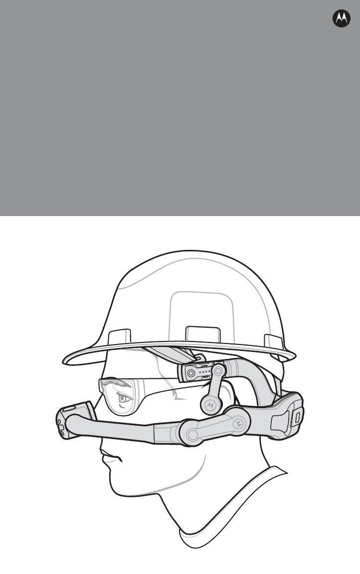
Introduction
This Quick Reference Guide explains how to install and charge the battery, proper install
the HC1 on the user’s head and install accessories.
Unpacking
Carefully remove all protective material from around the HC1 and save the shipping
container for later storage and shipping.
Verify that you received all equipment listed below:
• HC1 headset computer
•Computer/Optical Pod Assembly
•Firm Goods Assembly
• Lithium-ion battery (1950 or 4800 mAh)
• Speaker Module
• Camera (optional)
• Battery Cover (for 1950 or 4800 mAh battery)
• Quick Reference Guide.
Inspect the equipment for damage. If equipment is missing or damaged, contact the
Motorola Solutions Global Customer Support immediately. See Service Information on
backcover for contact information.
Review
e equ p e t o da age equ p e t s
he equipment for damag
S
olutions
G
lobal
C
ustomer
S
upport im
m
Solutions Global Customer Support imm
e
r
er
f
or contact in
f
ormation.
for contact information.
Copy
ssing
or
damaged,
contact
the
ing o
a
tely.
S
ee
ately. Se
S
ervice In
f
ormatio
nService Information
4 HC1 Headset Computer
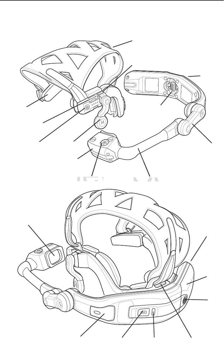
Features
Optical Pod
Headstrap
Optical Boom
Programmable
Function Button
Optical Focus
Computer/Optical Pod
Assembly
Pivot Arm
Firm Goods Assembly
Speaker
Module
Computer
Neck Pad
Audio Port
Accessory Port
Charging
Connector/Firm
Good Mount
Battery
Door
Door
Screw
LEDPower Button Release Latch
Display
SD Card Cover
USB
Port
Review
e
Op
tical Focus
Optical Focus
Copy
C
Optical Boo
mOptical Boom
Quick Reference Guide 5
Getting Started
Perform the following to setup the HC1 for the first time:
1. Install the battery
2. Charge the HC1
3. Determining dominant eye
4. Re-position Computer/Optical Pod Assembly
5. Re-position speaker module
6. Place the HC1 on head
7. Adjust head strap
8. Adjust optic pod.
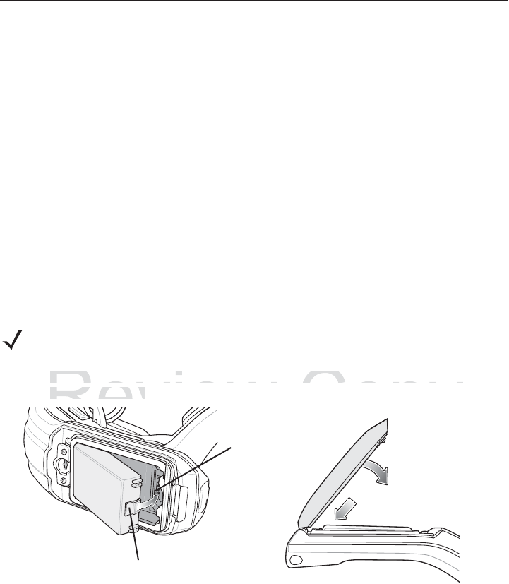
Installing the Battery
To install the battery:
1. Insert the battery into the battery well with the battery notches facing down and the
release latch facing up.
2. Rotate the battery into the battery well until it snaps into place. If the battery is charged,
the HC1 turns on.
3. Align the battery door with the housing.
4. Close battery door.
NOTE These procedure show the HC1 with a 1950 mAh battery. Some HC1 configurations
come with a 4800 mAh battery.
Battery Release LatchBattery Release Latch
Contacts
Review
the batter
y
into the batter
y
well with the
b
the battery into the battery well with the b
e latch facin
g
up.
e latch facing up.
evie
R
R
R
R
R
R
R
e
e
e
e
evie
e
e
e
R
R
R
Copy
e
r
y
notches facin
g
down and
try notches facing down and t
o
o
o
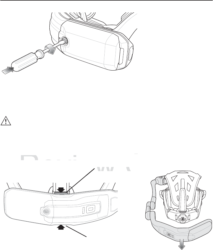
6 HC1 Headset Computer
5. Using a screwdriver or coin, turn the locking screw clockwise 1/4 turn to the lock
position.
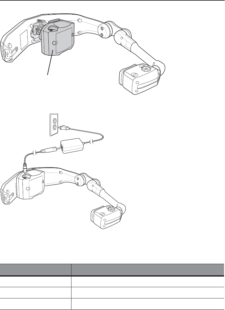
Charging the HC1
Before using the HC1, charge the battery. If a fully charged battery is installed, skip this
procedure.
1. Press the release latches to remove the Firm Goods Assembly from the
Computer/Optical Pod Assembly.
2. Connect the Charging Adapter to the Computer/Optical Pod Assembly.
CAUTION Do not place on head while charging.
Bottom Release Latch
Top Release Latch
Review
u
ter/Optical Pod Assembl
y
.
uter/Optical Pod Assembly.
T
o
p
R
e
l
ea
s
Top Relea
e
Copy
y
a
tc
htch
p
op
p
p
p
py
py
py
p
p
p
py
y
y
Quick Reference Guide 7
3. Plug the Power Supply plug into the Charging Adapter.
4. Plug the Power Supply into a wall outlet.
5. Charge until the LED turns green.
6. Press the Charging Adapter release latches and remove the Charging Adapter from the
Computer/Optical Pod Assembly.
LED State Description
Slow Flashing Amber HC1 is charging.
Solid Green HC1 is fully charged.
Fast Flashing Amber Charging Error.
Charging Adapter
Review
e
iew
Revie
Revie
Revie
Rev
vi
i
vie
e
e
e
v
v
v
v
v
v
e
e
v
v
i
i
i
i
i
i
e
R
R
R
R
e
e
e
e
e
e
e
e
e
e
Re
Re
R
R
R
Re
R
R
R
R
R
R
R
e
R
R
R
R
R
R
R
R
R
R
R
R
R
R
R
R
R
R
R
R
R
R
R
R
R
R
R
R
R
R
R
R
R
R
R
R
R
R
R
R
R
R
R
R
R
R
R
R
Cop
y
8 HC1 Headset Computer
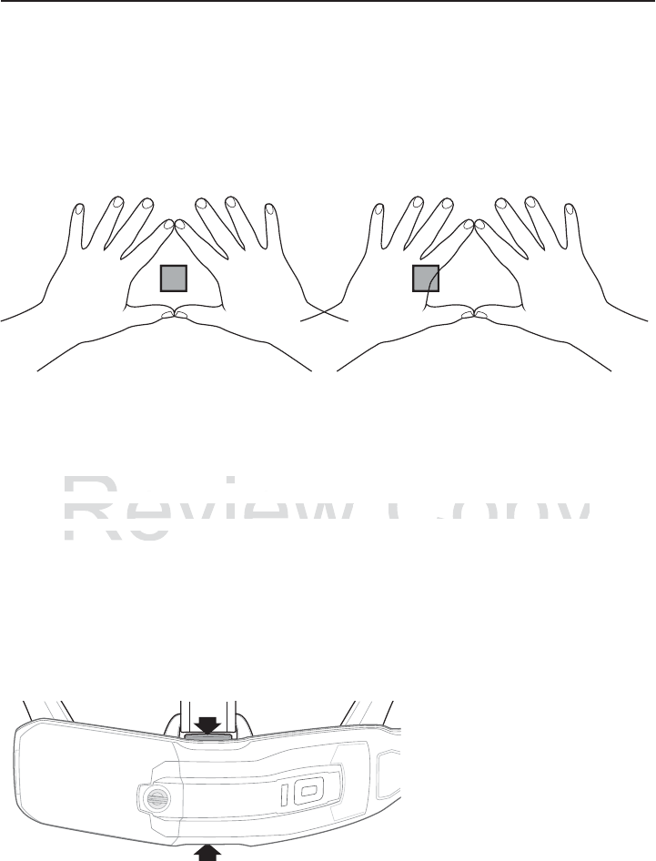
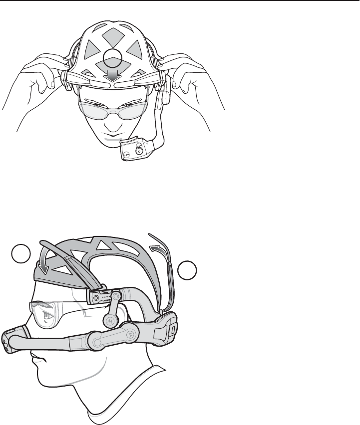
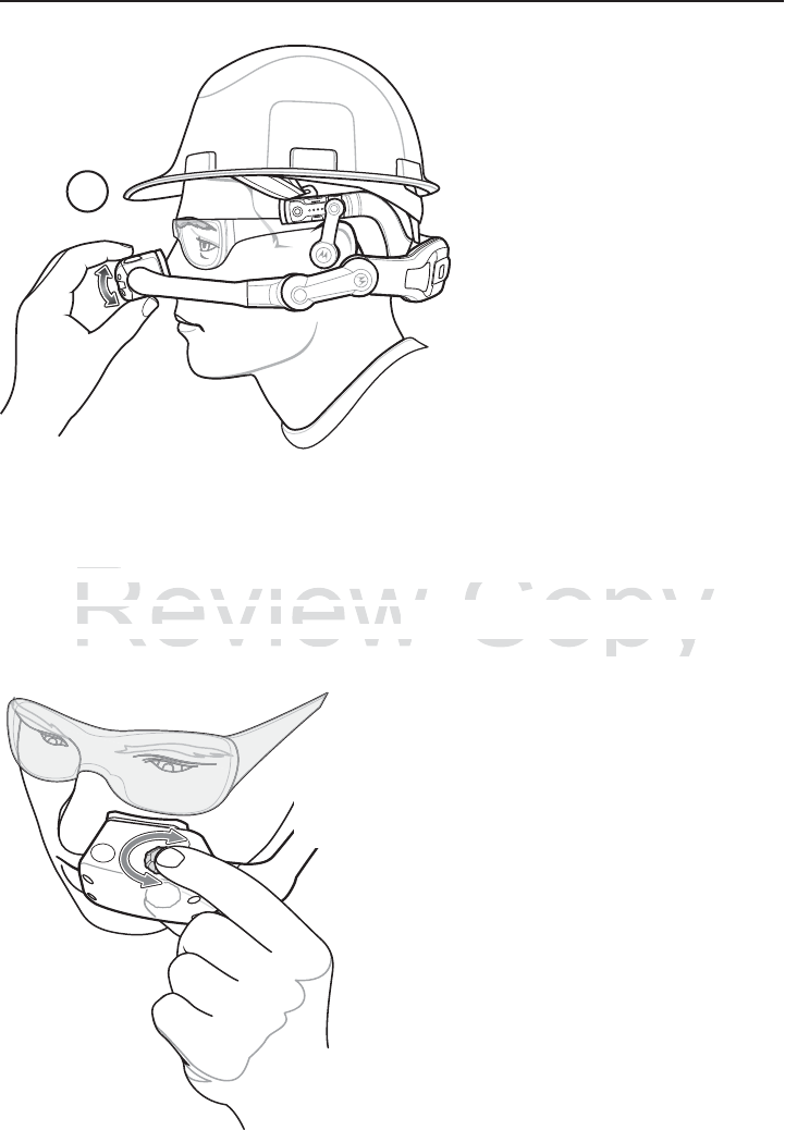
Determining Dominant Eye
Eye dominance is the tendency to prefer visual input from one eye to the other. Most
people are right-eye dominant; however in a small portion of the population neither eye is
dominant. It is best to use your dominant eye when viewing the display.
To determine which eye is dominant:
1. Place hands together as shown forming a triangle.
2. Keeping both eyes open, focus on any distant object.
3. Maintaining focus on the object centered in the triangle, close your right eye. If the object
is still in the triangle, you are left eye dominant.
4. Maintaining focus on the object centered in the triangle, close your left eye. If the object
is still in the triangle, you are right eye dominant.
5. If the object is in the triangle with either eye then you are dominant eye neutral.
6. Repeat test to confirm.
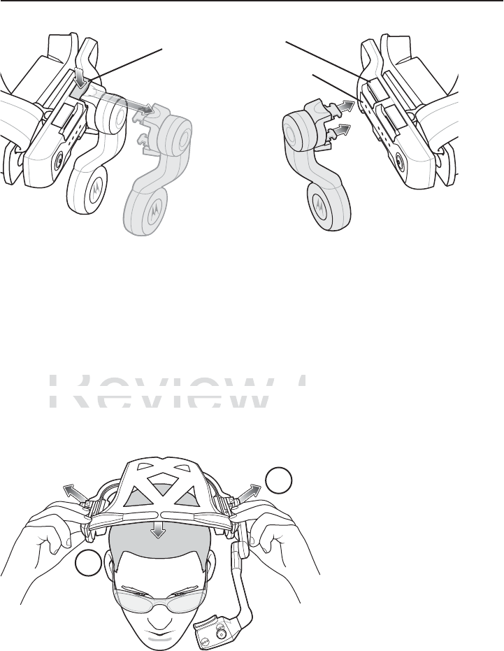
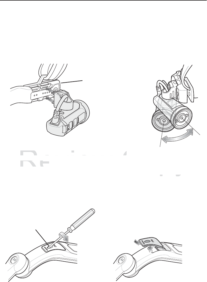
Re-positioning the Computer/Optical Pod Assembly
From the factory, the HC1 is configured for left eye dominant. To switch the optical pod
position:
1. If not already removed, press the release latches to remove the Firm Goods Assembly
from the Computer/Optical Pod Assembly.
2. Rotate the Computer/Optical Pod Assembly 180°.
Review
in the triangle, you are right eye domina
n
in the triangle, you are right
o
bject is in the triangle with either eye th
e
object is in the triangle with either eye the
at test to confirm.at test to confirm
Copy
o
u are dominant eye neutral.
ou are dominant eye neutral.
Quick Reference Guide 9
3. Reconnect the Firm Goods Assembly to the Computer/Optical Pod Assembly.
Re-positioning Speaker Module
1. Press release latch to remove Speaker Module from the Firm Good Assembly.
NOTE By default, the Speaker Module is installed on the right side. The user can switch the
Speaker Module to the left side if desired.
If switching the position of the Computer/Optical Pod Assembly was shifted it might be
necessary to re-position the Speaker Module.
Review
R
R
R
Rev
v
R
ev
v
e
e
e
e
e
e
e
e
e
e
e
e
e
e
e
e
e
e
e
e
Cop
y
10 HC1 Headset Computer
2. Align the Speaker Module on the opposite arm. Ensure that the Speaker Module is
connected to the mating connector with the two contacts.
3. Press the Speaker Module in until it snaps into place.
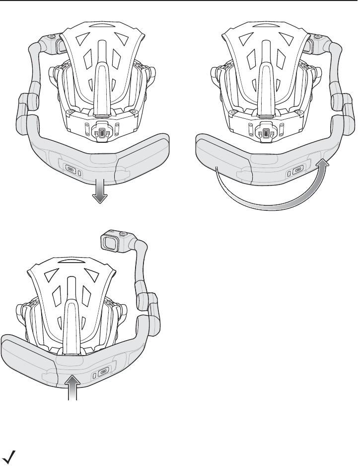
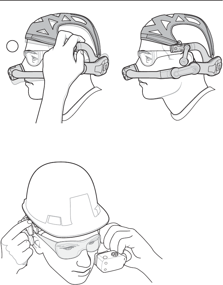
Placing the HC1 on Head
The HC1 is worn on the head so that the main body of the device fits behind the base of the
head with the strap sitting on top of the head.
1. If the HC1 is off, press the power button to turn it on.
2. Grasp the HC1 by the Firm Goods Assembly arms.
3. Pull the arms out to expand Firm Goods Assembly arms.
4. Position the HC1 over head.
5. Place the HC1 onto the head. The front of the headstrap must be positioned at the top of
the forehead.
Speaker Release Latch
Contacts
3
4
Review
H
C1 is off,
p
ress the
p
ower button to turn
HC1 is off, press the power button to turn
the H
C
1 by the Firm
G
oods Assembly a
r
the HC1 by the Firm Goods Assembly a
Copy
n
.
n.
arms
.
Quick Reference Guide 11
6. Re-position the back headstrap tab to position the height of the Computer/Optical Pod
Assembly.
7. Re-position the left and right headstrap tabs to position the arms above the ears.
Lengthen or shorten the head strap so that the ear loops are resting just above but not
touching the ears.
8. Make sure the HC1 is balanced on head like you would a pair of eyeglasses.
5
6
7
w
w
ew
w
R
Revie
R
e
ev
ev
evie
evie
ev
v
v
v
v
v
v
ev
v
v
v
v
v
v
vie
ie
i
R
v
v
i
i
i
i
i
i
i
v
e
v
v
ev
Revie
Review
Re
Re
Re
evie
R
R
Rev
Rev
Re
R
e
ev
w
w
w
w
w
w
6
Cop
y
12 HC1 Headset Computer
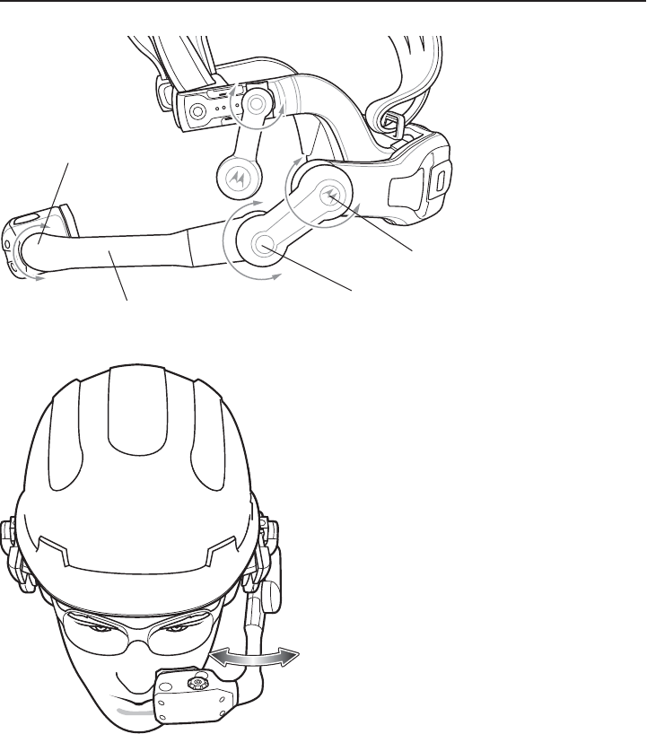
Adjusting the Optical Boom
When adjusting the HC1 boom, hold the arm on the side opposite the boom when moving
the boom up and down.
The HC1 pivot points allow the user to properly position the Optical Pod and to move the
Optical Pod when the user does not need to use it.
The Coarse Pivot Point allows for moving the Optical Pod large distances. The Fine Pivot
point allow for fine tuning of the position. The Pod Pivot point allow for positioning of the
display for viewing.
8
Review
Revie
Revie
Cop
y
Quick Reference Guide 13
Move the Optical Boom in or out to position under eye.
Position the optical boom so that the Optical Pod is positioned approximately two fingers
distance from the eye wear.
Coarse Pivot Point
Fine Pivot Point
Pod Pivot Point
Optical Boom
ew
e
e
e
e
e
e
e
e
e
e
e
Revie
e
Revi
R
vi
e
e
Cop
y
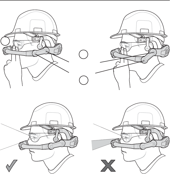
14 HC1 Headset Computer
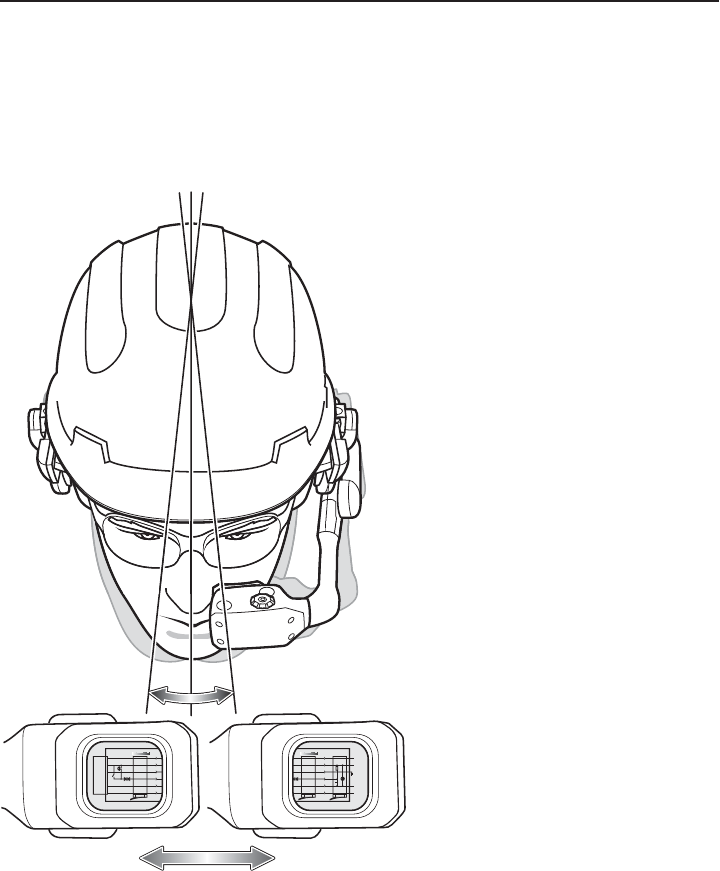
The Optical Pod must be positioned so that it does not block the line of sight of the user.
1. Hold the HC1 with one hand and rotate the arm at the Coarse Pivot Point.
2. Hold the HC1 with one hand and rotate the arm at the Fine Pivot Point.
3. Repeat adjustments until the Optical Pod is two finger lengths away from safety glasses
and out of the user’s line of sight.
4. Adjust the optical boom to position the display left or right.
5. Rotate the Optical Pod for best viewing angle.
Coarse Pivot Point
Fine Pivot Point
1
2
3
Review
e
e
R
R
Revie
Revie
e
e
e
e
e
e
R
Re
e
e
e
ev
vi
i
i
R
R
R
Re
e
e
e
e
e
e
e
e
Re
Re
e
e
e
R
Re
R
e
e
Re
Re
ev
v
e
ev
e
e
e
e
e
e
e
R
Re
e
Re
e
e
e
R
Re
Re
e
Re
e
Re
Rev
ev
ev
ev
ev
v
v
v
v
v
vie
vie
v
v
v
v
v
v
v
vi
vi
v
v
v
v
v
v
vi
v
v
v
v
v
i
vi
ie
ie
i
i
i
i
i
i
i
i
e
e
v
v
v
v
vie
vie
Review
Review
Ri
Review
Review
i
i
R
e
e
iew
iew
iew
ew
w
ew
ew
ew
w
e
e
Re
e
Re
Re
e
Re
Co
Co
Co
Co
Co
opy
o
o
o
o
o
o
o
o
op
y
y
y
y
o
o
o
o
o
o
o
o
o
o
o
o
o
o
o
o
o
o
o
opy
p
o
p
p
o
o
p
o
o
o
o
o
o
o
o
o
o
opy
py
py
py
p
p
p
y
py
p
p
py
py
py
py
y
y
y
y
y
y
y
y
y
y
y
y
y
y
py
y
y
y
y
y
y
y
y
y
o
o
o
o
o
o
o
o
Co
o
o
o
o
o
o
o
o
o
o
o
o
o
o
o
y
y
y
y
y
y
y
y
y
y
y
y
y
y
y
y
y
y
y
y
y
py
py
Copy
Copy
Copy
C
Co
p
y
y
y
Co
Co
C
o
o
p
p
p
y
y
y
py
py
py
p
p
y
y
y
y
y
y
p
y
y
Co
o
Co
Co
o
Co
Co
o
Co
Quick Reference Guide 15
Focus Display
To focus the display:
1. Look into the display.
2. There are two display dials for controlling the focus. One on top and one on the bottom.
With thumb and index finger, squeeze dials.
3. Rotate the display dials either clockwise or counter-clockwise until the display appears in
focus.
If the Computer/Optical Pod Assembly was rotated, the display appears upside down. Say
“My Computer” > “My Controls” > “Screen Rotation” > “Rotate Screen.” Refer to the HC1
User Guide for information on how to flip the display image.
5
Review
py
are two display dials
f
or controlling the
fo
are two display dials for controlling the fo
h
umb and index
f
inger, squeeze dials
.humb and index finger, squeeze dials.
e the display dials either clockwise or coun
e the display dials either clockwise or co
Copy
.
O
ne on top and one on the
b. One on top and one on the b
cl
oc
k
w
i
se unt
il
t
h
e
di
sp
l
ay ap
pockwise until the display a
16 HC1 Headset Computer
Basic Usage
Head Tracker Navigation
The HC1 contains 9-axis head tracking sensors that allow the user to move the objects on
the display by moving their head up and down and left and right.
As the user moves head left or right, the image on the display scrolls accordingly. Moving
the head up and down moves the image on the display accordingly.
Latch
Equipment Plug Master Socket
Leased
Line
Leased
Line
6 - 0
5 - R
4 - B
3 - G
2 - W 470k
1.6vF
1 - BK
A-Wire
B-Wire
Local
Earth
Latch
ell
eech
pression
Latch
Equipment Plug
6 - 0
5 - R
4 - B
3 - G
2 - W
1 - BK
Bell
Speech
Suppression
Dial
Off
Normal
Signal
Circuits
ew
e
e
ew
ew
vie
e
ew
ew
ew
vie
vie
vie
vi
e
vi
ie
e
v
v
v
v
v
v
e
e
e
e
e
e
e
R
R
R
Re
R
R
Re
R
R
Re
Re
R
R
Re
vie
i
vie
v
v
v
v
i
i
i
i
i
vie
i
vie
v
vie
v
e
v
e
v
Cop
y
Quick Reference Guide 17
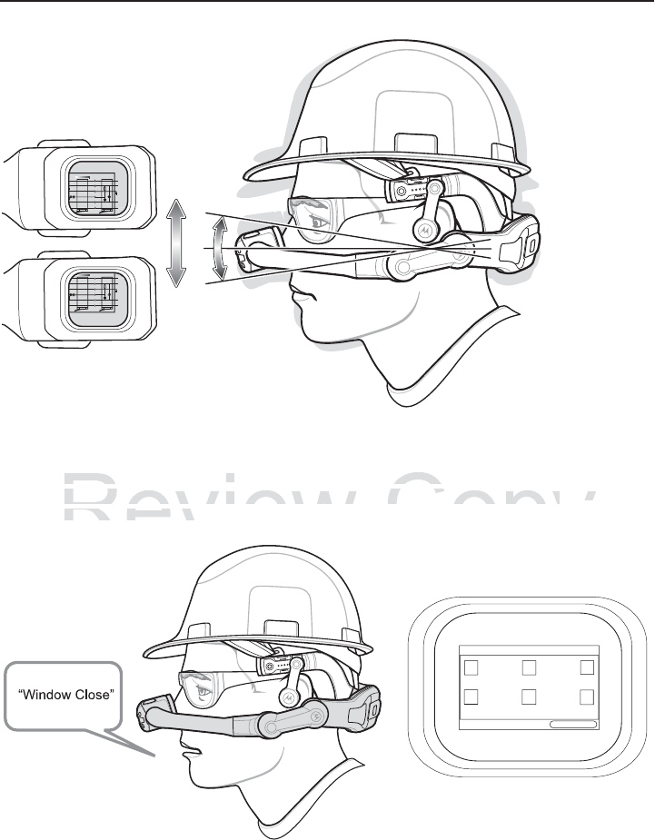
Voice Control
The HC1 is equipped with voice recognition software that allows the user to control
software functionality by speaking specific on-screen commands. Refer to the HC1 User
Guide for more information.
Latch
Equipment Plug Master Socket
Leased
Line
Leased
Line
6 - 0
5 - R
4 - B
3 - G
2 - W 470k
1.6vF
1 - BK
A-Wire
B-Wire
Local
Earth
Latch
Bell
Speech
ppression
Eq
E
E
se
ed
B
B
S
S
p
p
Latch
Equipment Plug Master Socket
Leased
Line
Leased
Line
6 - 0
5 - R
4 - B
3 - G
2 - W 470k
1.6vF
1 - BK
A-Wire
B-Wire
Local
Earth
Latch
Bell
Speech
ppression
d
d
B
B
S
S
p
p
My Controls
Window Close
Review
is
equipped
with
voice
recognition
softwa
is equipped with voice
functionalit
y
b
y
speakin
g
specific on-scr
e
functionality by speaking specific on-scre
r
m
o
r
e
in
fo
rm
a
ti
o
n
.r more information
Copy
that
allows
the
user
to
control
hat allo
c
ommands. Refer to the
commands. Refer to the
H
C
1
C1
18 HC1 Headset Computer
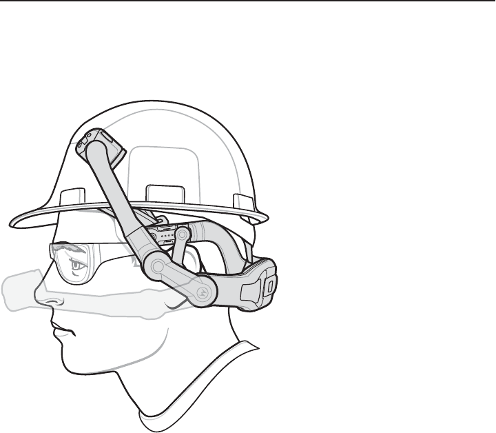
Positioning Optical Pod When not in Use
The user can move the Optical Pod away from the face when it is not being used for long
periods of time. Grasps the boom and rotate up and away from the face.
Review
iew
ew
Revie
Rev
vie
vie
ie
v
Rev
Re
Cop
y
Quick Reference Guide 19
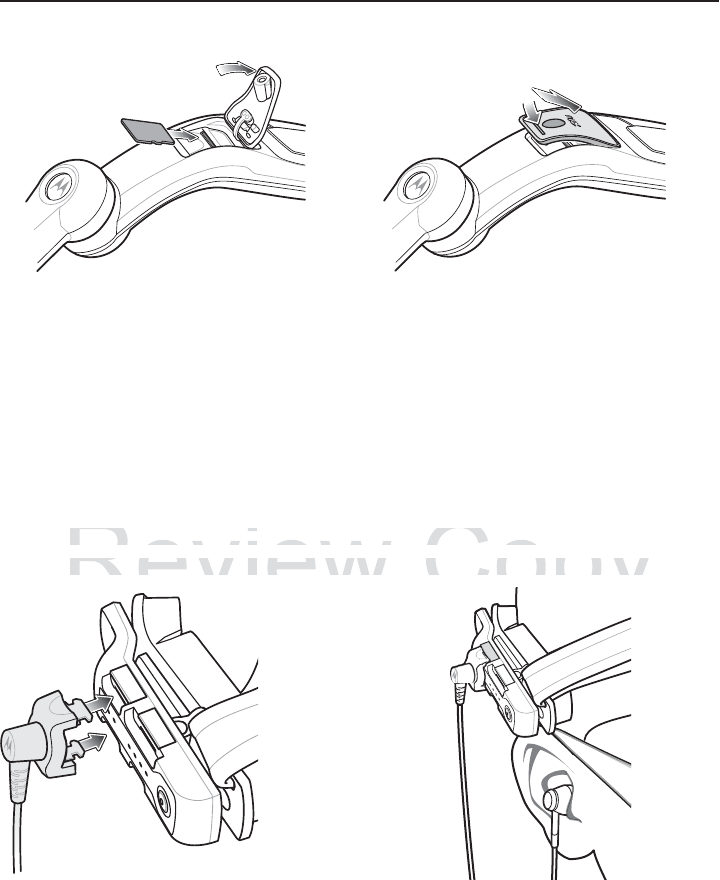
Accessories
Camera
Connect the optional Camera to either arm of the Firm Goods Assembly.
1. Attach the connector of the Camera to Accessory port on the Firm Goods Assembly.
2. Push in until it snaps into place.
3. Move camera left or right to position for best viewing.
microSD Card
The microSD card provides additional storage for data. To install a microSD card:
1. Press the Power button for one second to place the HC1 into suspend mode. The LED
flashes red momentarily and then turns off.
2. Using a #1 Phillips screwdriver, remove the screw securing the card cover.
3. Lift the card cover.
4. Insert the microSD card into the card slot with the contacts facing down.
Firm Goods Assembly Arm
Card Cover
Review
camera le
f
t or right to position
f
or best vi
e
camera left or right to position for best vie
SD Card
SD Card
Copy
g.
g.
a To install a microSD card:croSD car
20 HC1 Headset Computer
5. Close the card cover.
6. Secure the card cover using a #1 Phillips screwdriver.
7. Press the Power button to wake up the HC1.
Ear Buds
Ear Buds provide an optional solution for the user that requires ear protection to hear audio
from the HC1.
To install the Ear Buds:
1. Remove the Speaker Module from the Firm Goods Assembly arm.
2. Attach the connector of the Ear Buds to Audio port on the Firm Goods Assembly arm.
3. Place ear buds into ears.
4. Route the Ear Bud wire so that it does not interfere with movement.
Review
v
e the Speaker Module from the Firm G
o
ve the Speaker Module from the Firm Go
the connector o
f
the Ear Buds to Audio
p
the connector of the Ear Buds to Audio
e
Copy
Assembl
y
arm.
Assembly arm
o
n the Firm
G
oods Assembl
yon the Firm Goods Assembly
o
Quick Reference Guide 21
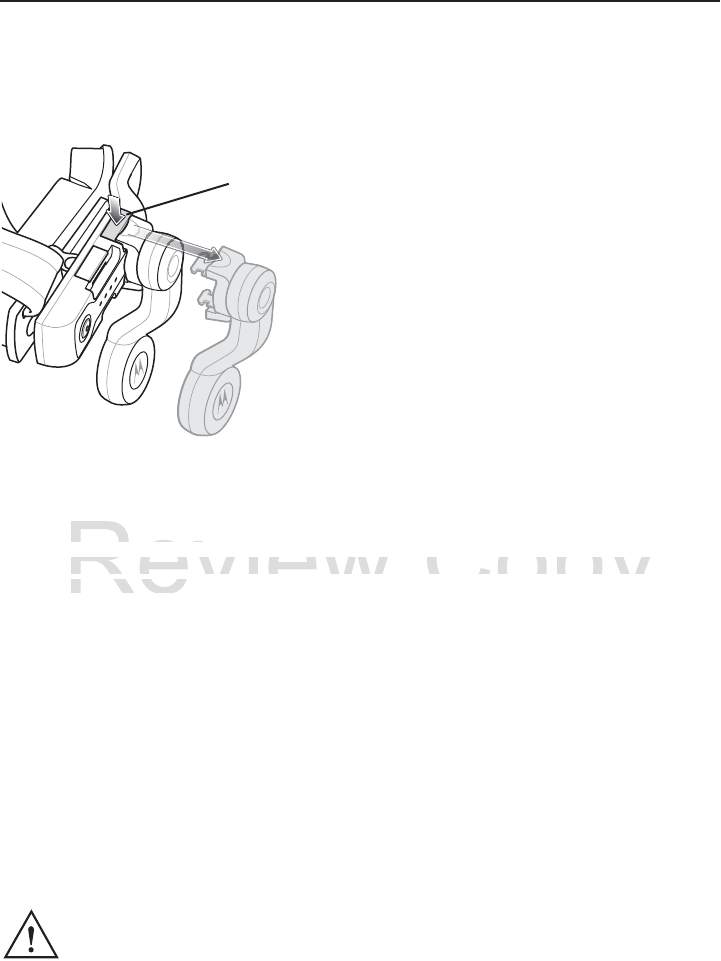
Remove Accessory
To remove the speaker, camera or ear bud:
1. Press the release button.
2. The accessory ejects slightly.
3. Remove the accessory.
Resetting the HC1
To reset the HC1 press the Power button for at least eight seconds. The display turns off
and the the HC1 reboots.
Regulatory Information
This device is approved under Motorola Solutions, Inc.
This guide applies to Model Number HC170.
All Motorola/Symbol devices are designed to be compliant with rules and regulations in
locations they are sold and will be labeled as required.
Local language translations are available at the following website:
http://supportcentral.motorolasolutions.com
Any changes or modifications to Motorola/Symbol Technologies equipment, not expressly
approved by Motorola/Symbol Technologies, could void the user's authority to operate the
equipment.
Declared maximum operating temperature: 50 °C.
CAUTION Only use Motorola/Symbol approved and UL Listed accessories, battery packs
and battery chargers.
Motorola devices are professionally installed, the Radio Frequency Output
Power will not exceed the maximum allowable limit for the country of operation.
Do NOT attempt to charge damp/wet mobile computers or batteries. All
components must be dry before connecting to an external power source.
Release Button
Review
tting the HC1
tting the HC
t
he HC1 press the Power button for at le
a
the HC1 press the Power button for at le
he H
C
1 reboots
.he HC1 reboot
Copy
e
i
g
ht seconds. The displa
y
tu
reight seconds. The display tu

22 HC1 Headset Computer
Bluetooth® Wireless Technology
This is an approved Bluetooth® product. For more information or to view End Product
Listing, please visit https://www.bluetooth.org/tpg/listings.cfm
Wireless Device Country Approvals
Regulatory markings, subject to certification, are applied to the device signifying the
radio(s) is/are approved for use in the following countries: United States, Canada,
Australia, and Europe 1.
Please refer to the Declaration of Conformity (DoC) for details of other country markings.
This is available at http://www.motorolasolutions.com/doc.
Note1: For 2.4 GHz or 5 GHz Products: Europe includes, Austria, Belgium, Bulgaria, Czech
Republic, Cyprus, Denmark, Estonia, Finland, France, Germany, Greece, Hungary,
Iceland, Ireland, Italy, Latvia, Liechtenstein, Lithuania, Luxembourg, Malta, Netherlands,
Norway, Poland, Portugal, Romania, Slovak Republic, Slovenia, Spain, Sweden,
Switzerland and the United Kingdom.
Country Roaming
This device incorporates the International Roaming feature (IEEE802.11d) which will
ensure the product operates on the correct channels for the particular country of use.
Frequency of Operation - FCC and IC
2.4 GHz Only
The available channels for 802.11 b/g operation in the US are Channels 1 to 13. The range
of channels is limited by firmware.
Health and Safety Recommendations
Ergonomic Recommendations
• Reduce or eliminate repetitive motion
• Maintain a natural position
• Reduce or eliminate excessive force
• Keep objects that are used frequently within easy reach
• Perform tasks at correct heights
• Reduce or eliminate vibration
• Reduce or eliminate direct pressure
• Provide adjustable workstations
Operation of the device without regulatory approval is illegal.
CAUTION In order to avoid or minimize the potential risk of ergonomic injury follow the
recommendations below. Consult with your local Health & Safety Manager to
ensure that you are adhering to your company's safety programs to prevent
employee injury.
Review
ce incorporates the International Roami
n
ce incorporates the International Roamin
h
e product operates on the correct chann
he product operates on the correct chann
ncy of Operation FCC and ICncy of Operation FCC and IC
Copy
a
ture
(
IEEE802.11d
)
which
wature (IEEE802.11d) which w
f
or the particular countr
y
of u
sfor the particular country of u

Quick Reference Guide 23
• Provide adequate clearance
• Provide a suitable working environment
• Improve work procedures.
Note: The following section is only applicable for mobile computers.
Vehicle Installation
RF signals may affect improperly installed or inadequately shielded electronic systems in
motor vehicles (including safety systems). Check with the manufacturer or its
representative regarding your vehicle. You should also consult the manufacturer of any
equipment that has been added to your vehicle.
An air bag inflates with great force. DO NOT place objects, including either installed or
portable wireless equipment, in the area over the air bag or in the air bag deployment area.
If in-vehicle wireless equipment is improperly installed and the air bag inflates, serious
injury could result.
Note: Connection to an alert device that will cause a vehicle horn to sound or lights to flash,
on receipt of a call on public roads, is not permitted.
IMPORTANT
Before installing or using, check state and local laws regarding windshield mounting and
use of equipment.
For safe Installation:
• Do not put your phone in a location that obstructs the drivers vision or interferes with the
operation of the Vehicle. Do not cover an airbag.
Please observe all warning notices with regard to the usage of wireless devices.
Potentially Hazardous Atmospheres - Vehicles Use
You are reminded of the need to observe restrictions on the use of radio devices in fuel
depots, chemical plants etc. and areas where the air contains chemicals or particles (such
as grain, dust, or metal powders) and any other area where you would normally be advised
to turn off your vehicle engine.
Safety in Aircraft
Switch off your wireless device whenever you are instructed to do so by airport or airline
staff. If your device offers a 'flight mode' or similar feature, consult airline staff as to its use
in flight.
Wireless devices transmit radio frequency energy and may affect medical electrical
equipment.
Warnings for Use of Wireless Devices
Safety in Hospitals
Review
qu p e t
qu p e
In
s
t
a
ll
a
ti
o
n:
Installation:
t
put
y
our phone in a location that obstru
c
t put your phone in a location that obstru
ifhVhilD ib
Vhil D t
Copy
h
e drivers vision or inter
f
eres
we drivers vision or interferes

24 HC1 Headset Computer
Wireless devices should be switched off wherever you are requested to do so in hospitals,
clinics or healthcare facilities. These requests are designed to prevent possible
interference with sensitive medical equipment.
Pacemakers
Pacemaker manufacturers recommended that a minimum of 15 cm (6 inches) be
maintained between a handheld wireless device and a pacemaker to avoid potential
interference with the pacemaker. These recommendations are consistent with independent
research and recommendations by Wireless Technology Research.
Persons with Pacemakers:
• Should ALWAYS keep the device more than 15 cm (6 inches) from their pacemaker
when turned ON.
• Should not carry the device in a breast pocket.
• Should use the ear furthest from the pacemaker to minimise the potential for
interference.
• If you have any reason to suspect that interference is taking place, turn OFF your
device.
Other Medical Devices
Please consult your physician or the manufacturer of the medical device, to determine if the
operation of your wireless product may interfere with the medical device.
Safety Information
Reducing RF Exposure - Use Properly
Only operate the device in accordance with the instructions supplied.
International
The device complies with internationally recognized standards covering human exposure
to electromagnetic fields from radio devices. For information on “International” human
exposure to electromagnetic fields refer to the Motorola/Symbol Declaration of Conformity
(DoC) at http://www.motorolasolutions.com/doc
Europe
Head Worn Devices
This device was tested for Head Mounted operation. Use only Motorola tested and
approved accessories to ensure EU Compliance.
RF Exposure Guidelines
Review
o
nsult your physician or the manu
f
acture
r
onsult your physician or
n
o
f
your wireless product may inter
f
ere
w
n of your wireless product may interfere w
RF Exposure GuidelinesRF Exposure Guidelines
Copy
h
e medical device, to determi
nhe medic
t
he medical device.
the medical device.

Quick Reference Guide 25
US and Canada
Head Worn Devices
This device was tested for typical body-worn operation. Use only Motorola tested and
approved accessories to ensure FCC / IC Compliance. The use of third-party accessories
may not comply with FCC / IC RF exposure compliance requirements, and should be
avoided.
To satisfy US and Canadian RF exposure requirements, a transmitting device must operate
with a minimum separation distance of 33.5 mm or more from a person's body.
Pour satisfaire aux exigences Américaines et Canadiennes d'exposition aux
radiofréquences, un dispositif de transmission doit fonctionner avec une distance de
séparation minimale de 33.5 mm ou plus de corps d'une personne.
LED Devices
Compliance statement for LED safety:
COMPLIES WITH IEC 60825-1:2001 (Ed.1.2) & IEC 62471:2006 (Ed.1.0); EN 62471:2008.
Power Supply
Use ONLY a Motorola approved UL LISTED ITE (IEC/EN 60950-1) power supply with
electrical ratings: Output 5.4 VDC, min 3 A, with a maximum ambient temperature of at
least 45 °C. Use of alternative power supply will invalidate any approvals given to this unit
and may be dangerous.
Battery Information
Use only Motorola approved batteries. Accessories which have battery charging capability
are approved for use with the following battery models:
Motorola BTRY-MC7XEAB0E (3.7 VDC, 1950 mAh)
Motorola BTRY-MC7XEAB0H (3.7 V DC, 4800 mAh)
Motorola/Symbol rechargeable battery packs are designed and constructed to the highest
standards within the industry.
However, there are limitations to how long a battery can operate or be stored before
needing replacement. Many factors affect the actual life cycle of a battery pack, such as
heat, cold, harsh environmental conditions and severe drops.
When batteries are stored over six (6) months, some irreversible deterioration in overall
battery quality may occur. Store batteries at half of full charge in a dry, cool place, removed
from the equipment to prevent loss of capacity, rusting of metallic parts and electrolyte
leakage. When storing batteries for one year or longer, the charge level should be verified
at least once a year and charged to half of full charge.
Replace the battery when a significant loss of run time is detected.
Standard warranty period for all Symbol batteries is one year, regardless if the battery was
purchased separately or included as part of the mobile computer or bar code scanner. For
more information on Symbol batteries, please visit:
http:/mysymbolcare.symbol.com/battery/batbasics1.html
Review
ratings:
Output
5
.
4
VDC
,
min
3
A
,
with
a
ratings: Output 5.4 VDC
°C
. Use o
f
alternative power suppl
y
will i
n
°C. Use of alternative power supply will in
be dangerous.
be dangerous.
If tiIf ti
Copy
ximum
ambient
temperature
o
imum a
d
ate an
y
approvals
g
iven to t
date any approvals given to t

26 HC1 Headset Computer
Battery Safety Guidelines
• The area in which the units are charged should be clear of debris and combustible
materials or chemicals. Particular care should be taken where the device is charged in a
non commercial environment.
• Follow battery usage, storage, and charging guidelines found in the HC1 User Guide.
• Improper battery use may result in a fire, explosion, or other hazard.
• To charge the mobile device battery, the battery and charger temperatures must be
between +32 ºF and +104 ºF (0 ºC and +40 ºC).
• Do not use incompatible batteries and chargers. Use of an incompatible battery or
charger may present a risk of fire, explosion, leakage, or other hazard. If you have any
questions about the compatibility of a battery or a charger, contact Motorola Enterprise
Mobility support.
• Do not disassemble or open, crush, bend or deform, puncture, or shred.
• Severe impact from dropping any battery-operated device on a hard surface could cause
the battery to overheat.
• Do not short circuit a battery or allow metallic or conductive objects to contact the battery
terminals.
• Do not modify or remanufacture, attempt to insert foreign objects into the battery,
immerse or expose to water or other liquids, or expose to fire, explosion, or other
hazard.
• Do not leave or store the equipment in or near areas that might get very hot, such as in a
parked vehicle or near a radiator or other heat source. Do not place battery into a
microwave oven or dryer.
• Battery usage by children should be supervised.
• Please follow local regulations to promptly dispose of used re-chargeable batteries.
• Do not dispose of batteries in fire.
• Seek medical advice immediately if a battery has been swallowed.
• In the event of a battery leak, do not allow the liquid to come in contact with the skin or
eyes. If contact has been made, wash the affected area with large amounts of water and
seek medical advice.
• If you suspect damage to your equipment or battery, contact Motorola Solutions Global
Customer Support to arrange for inspection.
Use with Hearing Aids
When some wireless devices are used near some hearing devices (hearing aids and
cochlear implants), users may detect a buzzing, humming, or whining noise. Some hearing
devices are more immune than others to this interference noise, and wireless devices also
vary in the amount of interference they generate. In the event of interference you may want
to consult your hearing aid supplier to discuss solutions.
Review
r
se or ex
p
ose
t
o wa
t
er or o
th
er
liq
u
id
s, or
rse or expose to water o
d
.
d.
t
leave or store the equipment in or near
a
t leave or store the equipment in or near
d hi l di t th h t
dhil dit thh
Copy
ose
t
o
fi
re, ex
pl
os
i
on, or o
the
ose to f
s
that mi
g
ht
g
et ver
y
hot, suc
hs that might get very hot, suc
r
ce. Do not place batter
y
into
e. Do not place battery int

Quick Reference Guide 27
Radio Frequency Interference Requirements- FCC
Note: This equipment has been tested and found to comply with the
limits for a Class B digital device, pursuant to Part 15 of the FCC
rules. These limits are designed to provide reasonable protection
against harmful interference in a residential installation. This
equipment generates, uses and can radiate radio frequency energy
and, if not installed and used in accordance with the instructions, may cause harmful
interference to radio communications. However there is no guarantee that interference will
not occur in a particular installation. If this equipment does cause harmful interference to
radio or television reception, which can be determined by turning the equipment off and on,
the user is encouraged to try to correct the interference by one or more of the following
measures:
• Reorient or relocate the receiving antenna
• Increase the separation between the equipment and receiver
• Connect the equipment into an outlet on a circuit different from that to which the receiver
is connected
• Consult the dealer or an experienced radio/TV technician for help.
Radio Transmitters (Part 15)
This device complies with Part 15 of the FCC Rules. Operation is subject to the following
two conditions: (1) this device may not cause harmful interference, and (2) this device must
accept any interference received, including interference that may cause undesired
operation.
Radio Frequency Interference Requirements- Canada
This Class B digital apparatus complies with Canadian ICES-003.
Cet appareil numérique de la classe B est conforme à la norme NMB-003 du Canada.
Radio Transmitters
This device complies with RSS 210 of Industry Canada. Operation is subject to the
following two conditions: (1) this device may not cause harmful interference and (2) this
device must accept any interference received, including interference that may cause
undesired operation.
Ce dispositif est conforme à la norme CNR-210 d'Industrie Canada applicable aux
appareils radio exempts de licence. Son fonctionnement est sujet aux deux conditions
suivantes: (1) le dispositif ne doit pas produire de brouillage préjudiciable, et (2) ce
dispositif doit accepter tout brouillage reçu, y compris un brouillage susceptible de
provoquer un fonctionnement indésirable.
Label Marking: The Term “IC:” before the radio certification only signifies that Industry
Canada technical specifications were met.
The use of 2.4GHz RLAN's, for use through the EEA, have the following restrictions:
Marking and European Economic Area (EEA)
Review
ce comp
li
es w
ith
P
ar
t
15
o
f
th
e
FCC
R
u
le
ce complies with Part 15
itions:
(
1
)
this device ma
y
not cause har
m
itions: (1) this device may not cause harm
ny
interference received, includin
g
interf
e
ny interference received, including interf
nn
Copy
O
pera
ti
on
i
s su
bj
ec
t
t
o
th
e
f
o
ll
Operatio
nterference, and
(
2
)
this devi
cnterference, and (2) this devic
c
e that ma
y
cause undesired
ce that may cause undesired

28 HC1 Headset Computer
• Maximum radiated transmit power of 100 mW EIRP in the frequency range
2.400 - 2.4835 GHz.
• Italy requires a user license for outside usage.
Bluetooth® Wireless Technology for use through the EEA has the following restrictions:
• Maximum radiated transmit power of 100mW EIRP in the frequency range
2.400 - 2.4835 GHz
• Italy requires a user license for outside usage.
Statement of Compliance
Motorola/Symbol hereby, declares that this device is in compliance with the essential
requirements and other relevant provisions of Directive 1999/5/EC. A Declaration of
Conformity may be obtained from http://www.motorolasolutions.com/doc.
TURKISH WEEE Statement of Compliance
EEE Yönetmeliine Uygundur
Brazils
Declarações Regulamentares para
Nota: “A marca de certificação se aplica ao Transceptor, modelo HC170. Este
equipamento opera em caráter secundário, isto é, não tem direito a proteção contra
interferência prejudicial, mesmo de estações do mesmo tipo, e não pode causar
interferência a sistemas operando em caráter primário.”
Para maiores informações sobre ANATEL consulte o site: www.anatel.gov.br
Review
marca
de
certificação
se
aplica
ao
Trans
marca de certificação se
e
nto opera em caráter secundário, isto é
ento opera em caráter secundário, isto é
n
cia prejudicial, mesmo de esta
ç
ões do
m
ncia prejudicial, mesmo de estações do m
n
cia a sistemas o
p
erando em caráter
p
ri
m
ncia a sistemas operando em caráter pr
Copy
tor
,
modelo
HC170
.
Este
or, mod
o
tem direito a prote
ç
ão cont
ro tem direito a proteção contr
m
o tipo, e não pode causar
mo tipo, e não pode causar
o
.”
”
it t l b

Quick Reference Guide 29
English: For EU Customers: All products at the end of their life must be returned to
Motorola for recycling. For information on how to return product, please go to:
http://www.motorolasolutions.com/recycling/weee.
Français : Clients de l'Union Européenne : Tous les produits en fin de cycle de vie doivent
être retournés à Motorola pour recyclage. Pour de plus amples informations sur le retour
de produits, consultez : http://www.motorolasolutions.com/recycling/weee.
Español: Para clientes en la Unión Europea: todos los productos deberán entregarse a
Motorola al final de su ciclo de vida para que sean reciclados. Si desea más información
sobre cómo devolver un producto, visite:
http://www.motorolasolutions.com/recycling/weee.
Deutsch: Für Kunden innerhalb der EU: Alle Produkte müssen am Ende ihrer
Lebensdauer zum Recycling an Motorola zurückgesandt werden. Informationen zur
Rücksendung von Produkten finden Sie unter
http://www.motorolasolutions.com/recycling/weee.
Italiano: per i clienti dell'UE: tutti i prodotti che sono giunti al termine del rispettivo ciclo di
vita devono essere restituiti a Motorola al fine di consentirne il riciclaggio. Per informazioni
sulle modalità di restituzione, visitare il seguente sito Web:
http://www.motorolasolutions.com/recycling/weee.
Português: Para clientes da UE: todos os produtos no fim de vida devem ser devolvidos à
Motorola para reciclagem. Para obter informações sobre como devolver o produto, visite:
http://www.motorolasolutions.com/recycling/weee.
Nederlands: Voor klanten in de EU: alle producten dienen aan het einde van hun
levensduur naar Motorola te worden teruggezonden voor recycling. Raadpleeg
http://www.motorolasolutions.com/recycling/weee voor meer informatie over het
terugzenden van producten.
Polski: Klienci z obszaru Unii Europejskiej: Produkty wycofane z eksploatacji nale¿y
zwróciæ do firmy Motorola w celu ich utylizacji. Informacje na temat zwrotu produktów
znajduj¹ siê na stronie internetowej http://www.motorolasolutions.com/recycling/weee.
eština: Pro zákazníky z EU: Všechny produkty je nutné po skonèení jejich životnosti
vrátit spoleènosti Motorola k recyklaci. Informace o zpùsobu vrácení produktu najdete na
webové stránce: http://www.motorolasolutions.com/recycling/weee.
Eesti: EL klientidele: kõik tooted tuleb nende eluea lõppedes tagastada taaskasutamise
eesmärgil Motorola'ile. Lisainformatsiooni saamiseks toote tagastamise kohta külastage
palun aadressi: http://www.motorolasolutions.com/recycling/weee.
Magyar: Az EU-ban vásárlóknak: Minden tönkrement terméket a Motorola vállalathoz kell
eljuttatni újrahasznosítás céljából. A termék visszajuttatásának módjával kapcsolatos
tudnivalókért látogasson el a http://www.motorolasolutions.com/recycling/weee weboldalra.
Slovenski: Za kupce v EU: vsi izdelki se morajo po poteku življenjske dobe vrniti podjetju
Motorola za reciklažo. Za informacije o vraèilu izdelka obišèite:
http://www.motorolasolutions.com/recycling/weee.
Svenska: För kunder inom EU: Alla produkter som uppnått sin livslängd måste returneras
till Motorola för återvinning. Information om hur du returnerar produkten finns på
http://www.motorolasolutions.com/recycling/weee.
Waste Electrical and Electronic Equipment (WEEE)
Review
ê
s:
ês:
Para clientes da UE: todos os produt
o
Para clientes da UE: todos os produto
para reciclagem. Para obter in
f
ormaçõe
s
para reciclagem. Para obter informaçõe
w.motorolasolutions.com
/
recycling
/
weee
w.motorolasolutions.com/recycling/weee
d
V klt idEUll dt
kl t idEU
Copy
o
f
im de vida devem ser devo
o fim de vida devem ser devo
b
re como devolver o produto
,bre como devolver o produto
e
nen aan
h
et e
i
n
d
e van
h
un
en aan het einde van hu

30 HC1 Headset Computer
Suomi: Asiakkaat Euroopan unionin alueella: Kaikki tuotteet on palautettava
kierrätettäväksi Motorola-yhtiöön, kun tuotetta ei enää käytetä. Lisätietoja tuotteen
palauttamisesta on osoitteessa http://www.motorolasolutions.com/recycling/weee.
Dansk: Til kunder i EU: Alle produkter skal returneres til Motorola til recirkulering, når de er
udtjent. Læs oplysningerne om returnering af produkter på:
http://www.motorolasolutions.com/recycling/weee.
: ..: , ,
Motorola .
,
http://www.motorolasolutions.com/recycling/weee .
Malti: Gal klijenti fl-UE: il-prodotti kollha li jkunu waslu fl-aar tal-ajja ta' l-uu taghom,
iridu jiu rritornati gand Motorola gar-riikla. Gal aktar tagrif dwar kif gandek
tirritorna l-prodott, jekk jogbok ur: http://www.motorolasolutions.com/recycling/weee.
Slovenina: Pre zákazníkov z krajín EU: Všetky výrobky musia by po uplynutí doby ich
životnosti vrátené spolonosti Motorola na recykláciu. Bližšie informácie o vrátení výrobkov
nájdete na: http://www.motorolasolutions.com/recycling/weee.
Lietuvi: ES vartotojams: visi gaminiai, pasibaigus j eksploatacijos laikui, turi bti gržinti
utilizuoti kompanij „Motorola“. Daugiau informacijos, kaip gržinti gamin, rasite:
http://www.motorolasolutions.com/recycling/weee.
Latviešu: ES klientiem: visi produkti pc to kalpošanas mža beigm ir jnogd atpaka
Motorola otrreizjai prstrdei. Lai iegtu informciju par produktu nogdšanu Motorola,
ldzu, skatiet: http://www.motorolasolutions.com/recycling/weee.
Türkçe: AB Müterileri için: Kullanm süresi dolan tüm ürünler geri dönütürme için
Motorola'ya iade edilmelidir. Ürünlerin nasl iade edilecei hakknda bilgi için lütfen u
adresi ziyaret edin: http://www.motorolasolutions.com/recycling/weee
Review
katiet:
http://www
.
motorolasolutions
.
com/r
katiet: http://www.motoro
A
B M
üAB Mü
terileri i
ç
in: Kulla
nerileri için: Kulla
m süresi dola
n
m süresi dolan
'y
a iade edilmelidir. Ürünlerin na
s'ya iade edilmelidir. Ürünlerin nas
l i
ade
e
iade e
y
aret edin: htt
p
://www.motorolasolutions.
c
yaret edin: http://www.motorolasolutions
Copy
cling/weee
.
ng/we
m
ürünler
g
eri dön
üm ürünler geri dönü
türme i
ç
i
ntürme için
cece
i h
a
k
kakk
nda bilgi i
ç
in lütfen
nda bilgi için lütfen
/
rec
y
clin
g
/weee
recycling/weee

Quick Reference Guide 31
Software Support
Motorola wants to ensure that customers have the latest release of entitled software at the
time of product purchase.
To confirm that your Motorola Solutions device shipped with the latest release of entitled
software, visit: www.motorolasolutions.com/support. Check for the latest software from
Software Downloads > Product Line/Product > Go.
If your device does not have the latest entitled software release as of your product
purchase date, please e-mail a request to Motorola at:
entitlementservices@motorolasolutions.com.
You must include the following essential device information with your request:
• Model number
• Serial number
• Proof of purchase
• Title of the software download you are requesting.
If it is determined by Motorola that your device is entitled to the latest software release, you
will receive an e-mail containing a link directing you to a Motorola Web site to download the
appropriate software.
R
eview Cop
y

Motorola Solutions, Inc.
1301 E. Algonquin Rd.
Schaumburg, IL 60196-1078, U.S.A.
http://www.motorolasolutions.com
MOTOROLA, MOTO, MOTOROLA SOLUTIONS and the Stylized M Logo are trademarks or
registered trademarks of Motorola Trademark Holdings, LLC and are used under license. All other
trademarks are the property of their respective owners.
© 2013 Motorola Solutions, Inc. All Rights Reserved.
72-165008-01 Rev. A - March 2013
R
eview Cop
y