Zebra Technologies MC3190 Mobile Computer User Manual UserMan Part3
Zebra Technologies Corporation Mobile Computer UserMan Part3
UserManual.wiki
>
Zebra Technologies
>
MC3190 User Manual
>
UserMan Part3
Contents
1.
UserMan Part1
2.
UserMan Part2
3.
UserMan Part3
4.
UserMan Part4
UserMan Part3
Navigation menu
Upload a User Manual
Namespaces
Wiki Guide
HTML
PDF
Info
Views
User Manual
Discussion / Help
Navigation
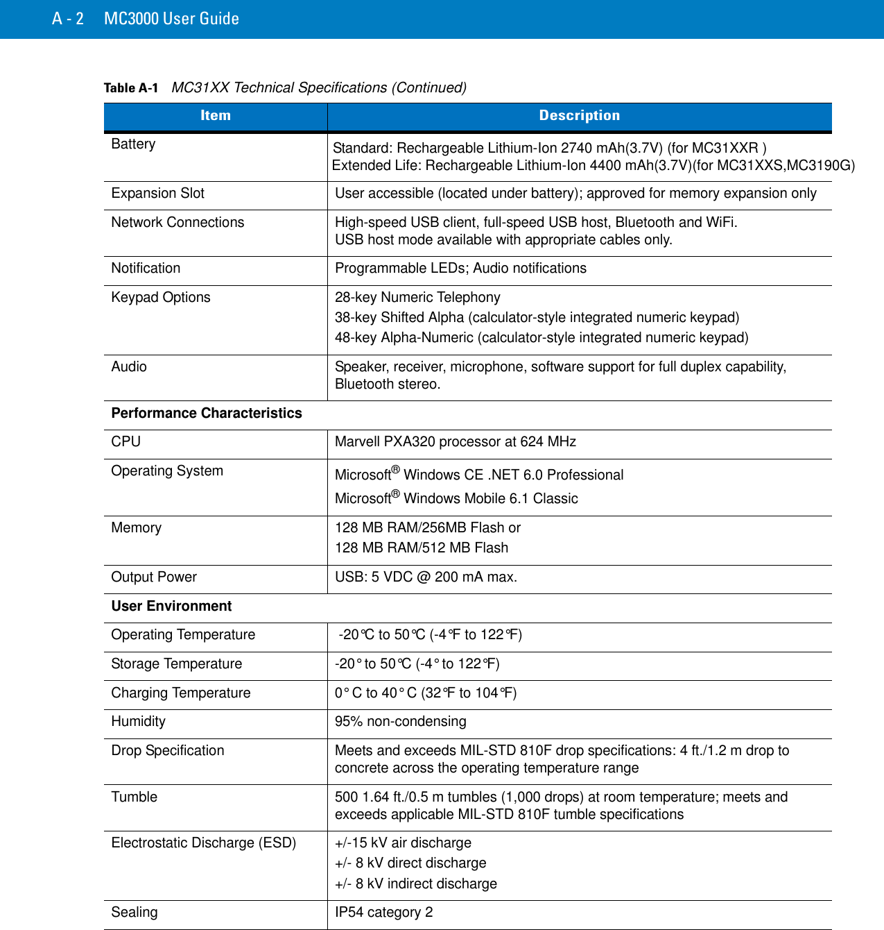
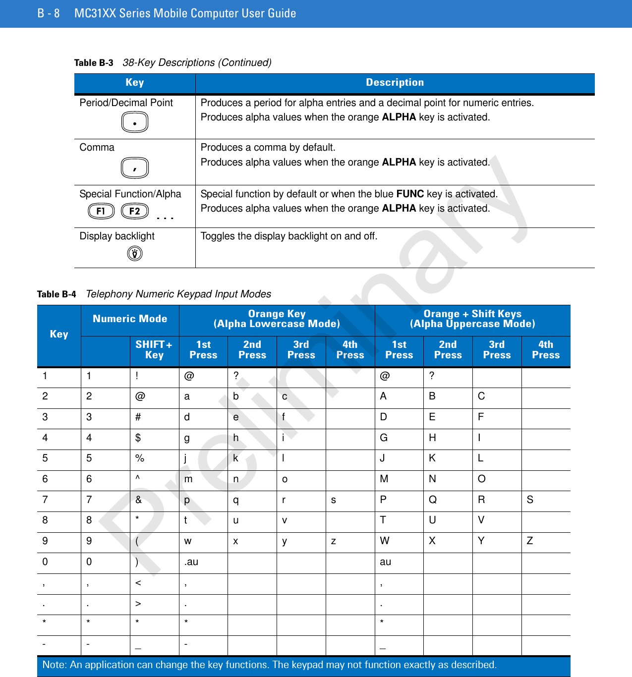
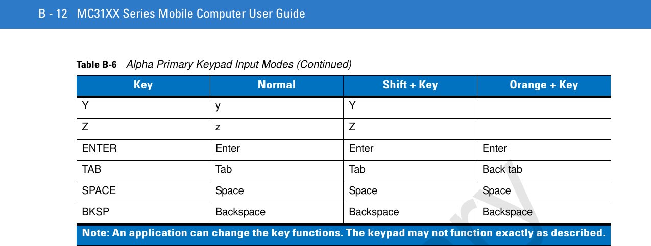
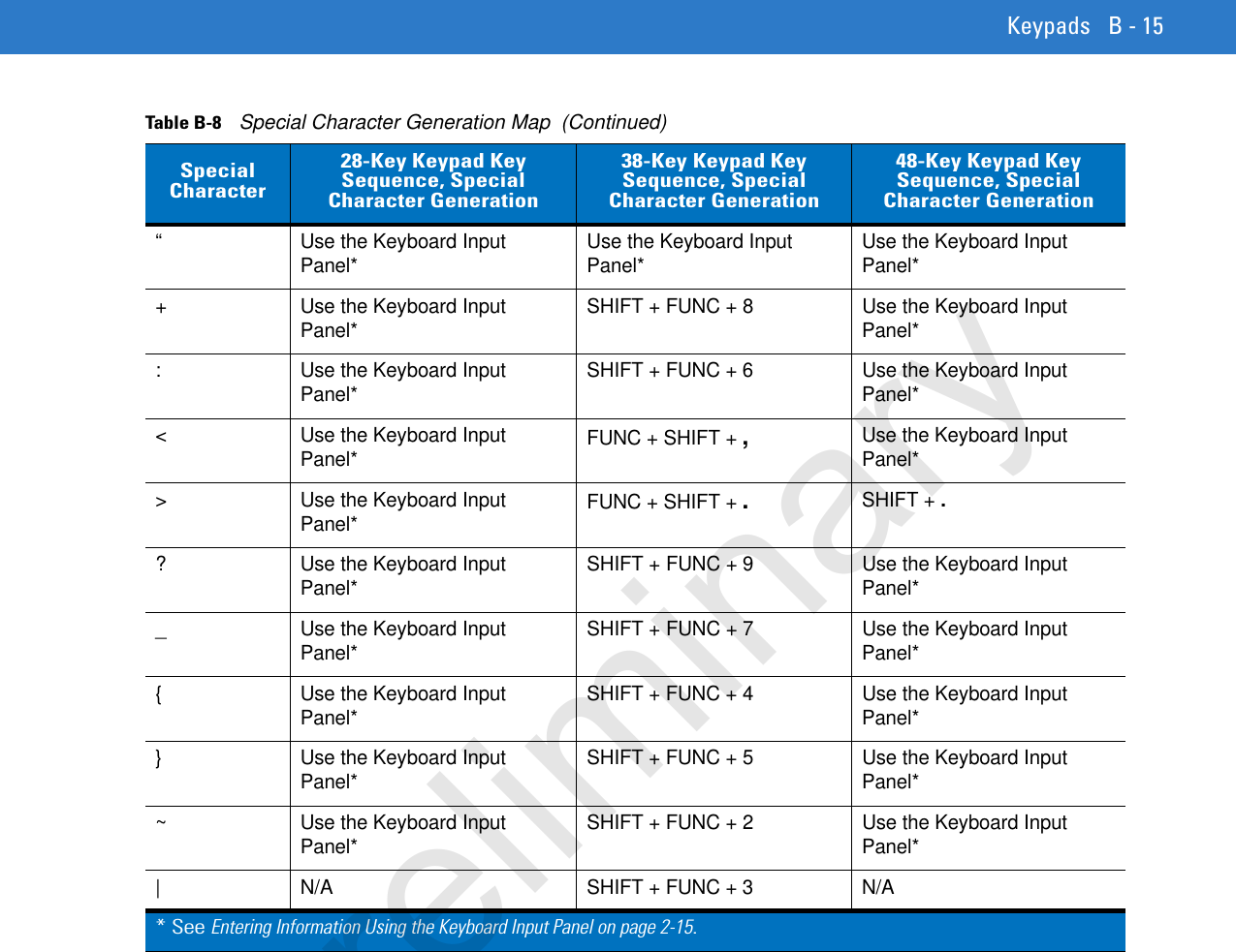
![B - 14 MC31XX Series Mobile Computer User GuideTable B-8 Special Character Generation Map Special Character28-Key Keypad Key Sequence, Special Character Generation38-Key Keypad Key Sequence, Special Character Generation48-Key Keypad Key Sequence, Special Character Generation[ Use the Keyboard Input Panel* FUNC + 4 FUNC + T] Use the Keyboard Input Panel* FUNC + 5 FUNC + U/ Use the Keyboard Input Panel* FUNC + 9 FUNC + Q\ Use the Keyboard Input Panel* FUNC + 3 Use the Keyboard Input Panel*= Use the Keyboard Input Panel* FUNC + 8 FUNC + P; Use the Keyboard Input Panel* FUNC + 6 FUNC + V- Use the Keyboard Input Panel* FUNC + 7 FUNC + O` Use the Keyboard Input Panel* FUNC + 2 FUNC + Y“ Use the Keyboard Input Panel* SHIFT + FUNC + 1 Use the Keyboard Input Panel*! SHIFT + 1 SHIFT + 1 SHIFT + 1@ SHIFT + 2 SHIFT + 2 SHIFT + 2# SHIFT + 3 SHIFT + 3 SHIFT + 3$ SHIFT + 4 SHIFT + 4 SHIFT + 4% SHIFT + 5 SHIFT + 5 SHIFT + 5^ SHIFT + 6 SHIFT + 6 SHIFT + 6& SHIFT + 7 SHIFT + 7 SHIFT + 7* SHIFT + 8 SHIFT + 8 SHIFT + 8( SHIFT + 9 SHIFT + 9 or FUNC + SHIFT + 9 SHIFT + 9) SHIFT + 0 SHIFT + 0 or FUNC + SHIFT + 0 SHIFT + 0‘ Use the Keyboard Input Panel* FUNC + 1 FUNC + X* See Entering Information Using the Keyboard Input Panel on page 2-15.Preliminary](https://usermanual.wiki/Zebra-Technologies/MC3190.UserMan-Part3/User-Guide-1178249-Page-41.png)