Zebra Technologies MC3190 Mobile Computer User Manual UserMan Part3
Zebra Technologies Corporation Mobile Computer UserMan Part3
Contents
- 1. UserMan Part1
- 2. UserMan Part2
- 3. UserMan Part3
- 4. UserMan Part4
UserMan Part3

Accessories 4 - 5
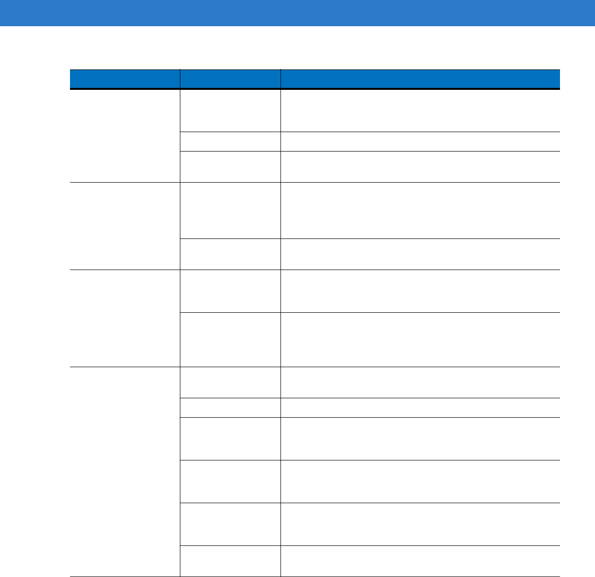
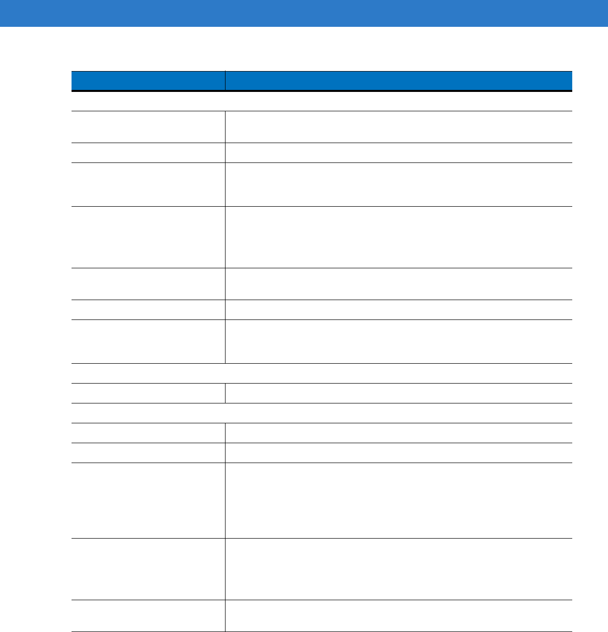
Table 4-2
LED Charging Status Indicators
LED Indication
Mobile Computer Charging (LED on mobile computer)
Off Mobile computer not placed correctly in the cradle; cable not connected correctly;
charger is not powered.
Fast Blinking Amber Error in charging; check placement of mobile computer.
Slow Blinking Amber Mobile computer is charging.
Solid Amber Charging complete.
Note: When the battery is initially inserted in the mobile computer, the amber LED flashes
once if the battery power is low or the battery is not fully inserted.
Spare Battery Charging (LED on cradle)
Off No spare battery in slot; spare battery not placed correctly; cradle is not powered.
Fast Blinking Amber Error in charging; check placement of spare battery.
Slow Blinking Amber Spare battery is charging.
Solid Amber Charging complete.
Preliminary
4 - 6 MC31XX Series Mobile Computer User Guide
Four Slot Cradles
There are two four slot cradles, Four Slot Charge Only cradle and Four Slot Ethernet cradle. The Four Slot
Ethernet cradle provides Ethernet communications. Both four slot cradles:
•
Provide 5.4 VDC power for operating the mobile computer and charging the battery.
•
Simultaneously charges up to four mobile computers.
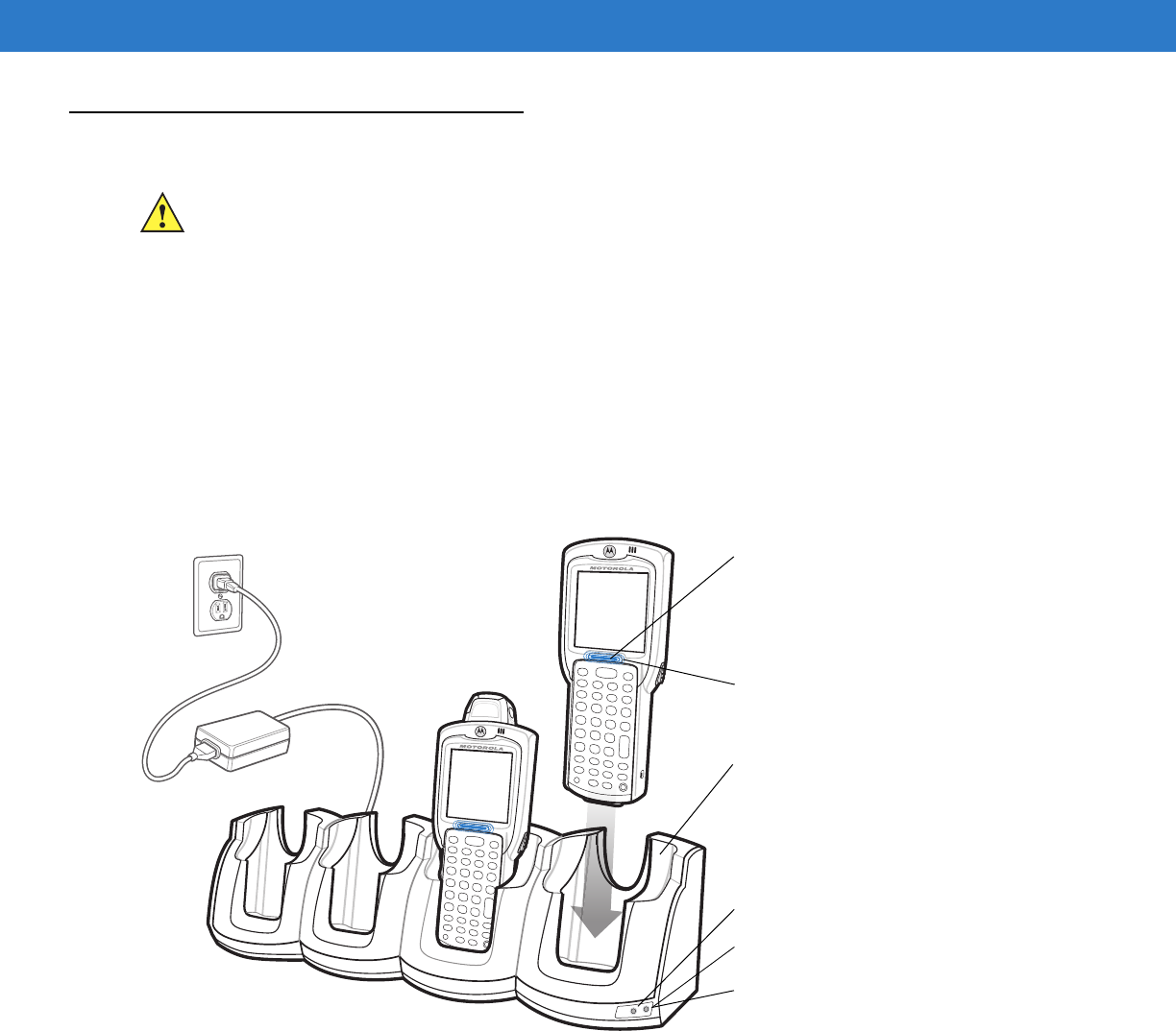
Battery Charging
The four slot cradle can charge up to four mobile computers simultaneously. To charge the mobile computer:
1. Slide the mobile computer into the mobile computer slot.
Figure 4-2
Four Slot Cradles
2. The mobile computer amber Charge LED Indicator, indicates the mobile computer battery charging status. The
Standard Battery usually charges in less than four hours and the Extended Life Battery usually charges in less
than six hours. See Table 4-2 for charging status indications.
3. When charging is complete, remove the mobile computer from the cradle.
LED Charge Indications
The Four Slot cradles use the mobile computer amber Charge LED Indicator to indicate the battery charging
status. See Table 4-2 on page 4-5 for charging status indications.
CAUTION Ensure that you follow the guidelines for battery safety described in Battery Safety Guidelines on page 5-2.
Scan/Charge Indicator LED Bar
Mobile Computer Slot
Charge LED Indicator (amber)
Speed LED (Ethernet Cradle Only)
Link LED (Ethernet Cradle Only)
Power LED (Charge Only Cradle)
Preliminary

Accessories 4 - 7
Power LED
The green Power LED (only on the Four Slot Charge Only cradle) lights to indicate that the Four Slot Charge Only
cradle is connected to a power source.
Speed LED
The green Speed LED (only on the Four Slot Ethernet cradle) lights to indicate that the transfer rate is 100 Mbps.
When it is not lit it indicates that the transfer rate is 10 Mbps.
Link LED
The yellow Link LED (only on the Four Slot Ethernet cradle) blinks to indicate activity, or stays lit to indicate that a
link is established. When it is not lit, it indicates that there is no link.
Preliminary
4 - 8 MC31XX Series Mobile Computer User Guide
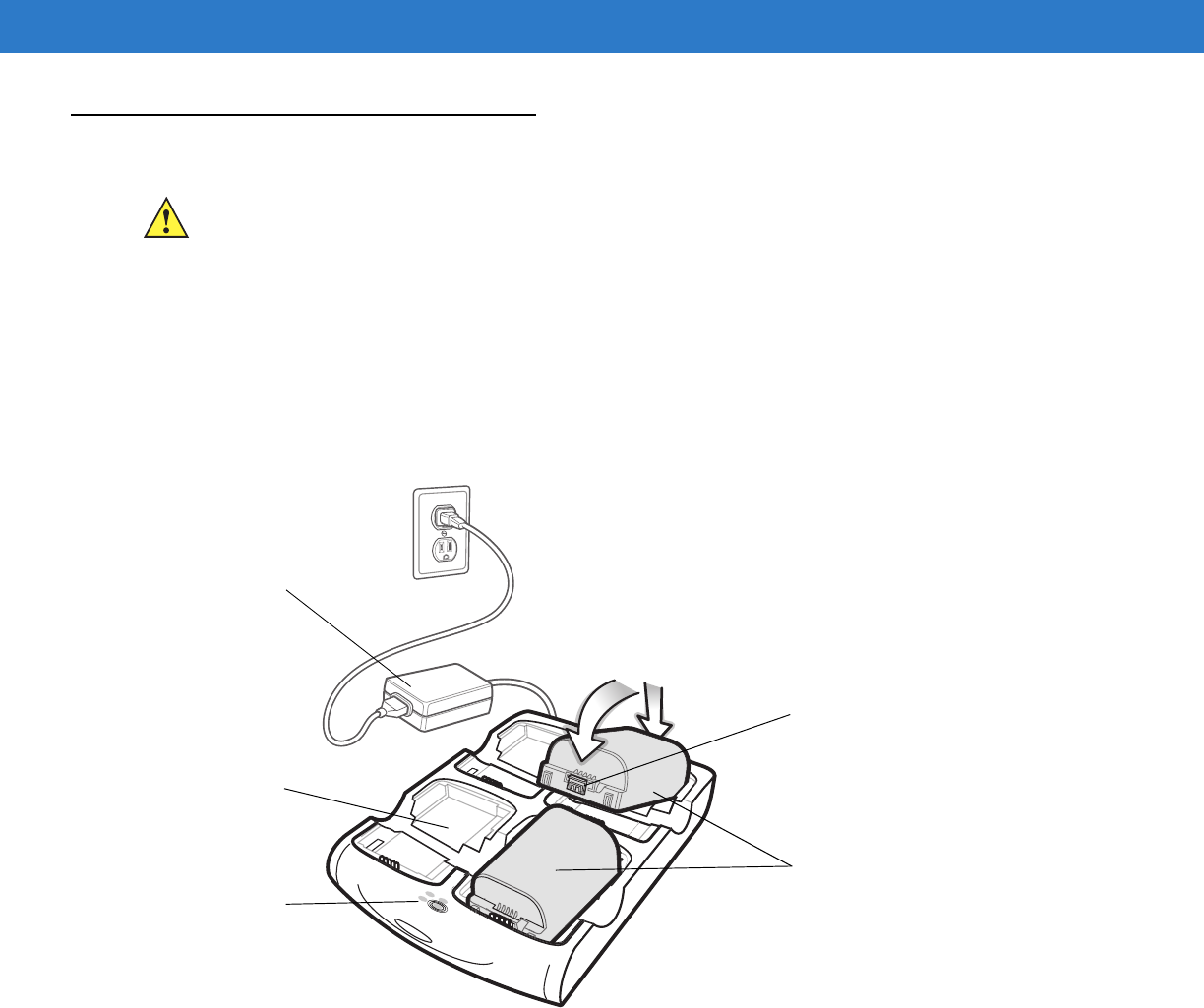
Four Slot Spare Battery Charger
The Four Slot Spare Battery Charger simultaneously charges up to four spare batteries.
Spare Battery Charging
To charge up to four MC31XX spare batteries:
1. Insert the spare battery into the spare battery charging slot, bottom first.
2. Pivot the top of the battery down onto the contact pins.
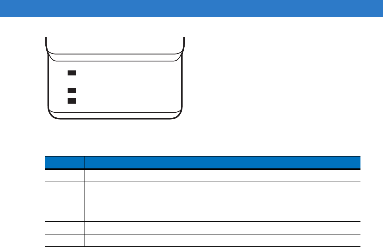
Figure 4-3
Four Slot Spare Battery Charger
3. Gently press down on the battery to ensure proper contact. The Standard Battery usually charges in less than
four hours and the Extended Life Battery usually charges in less than six hours. See Table 4-2 on page 4-5 for
charging status indications.
4. When charging is complete, press the battery clip and lift battery out of the slot.
LED Charge Indications
The Spare Battery Charging LEDs indicate the spare battery charging status. The Spare Battery Charging LEDs
are arranged in the same pattern as the spare battery charging slots so that the charging status of each battery can
be identified. See Table 4-2 on page 4-5 for charging status indications.
CAUTION Ensure that you follow the guidelines for battery safety described in Battery Safety Guidelines on page 5-2.
Power Supply
Spare
Batteries
Spare
Battery
Charging
Slot
Spare Battery
Charging
LEDs (4)
Battery
Clip
1
2
Preliminary
Accessories 4 - 9
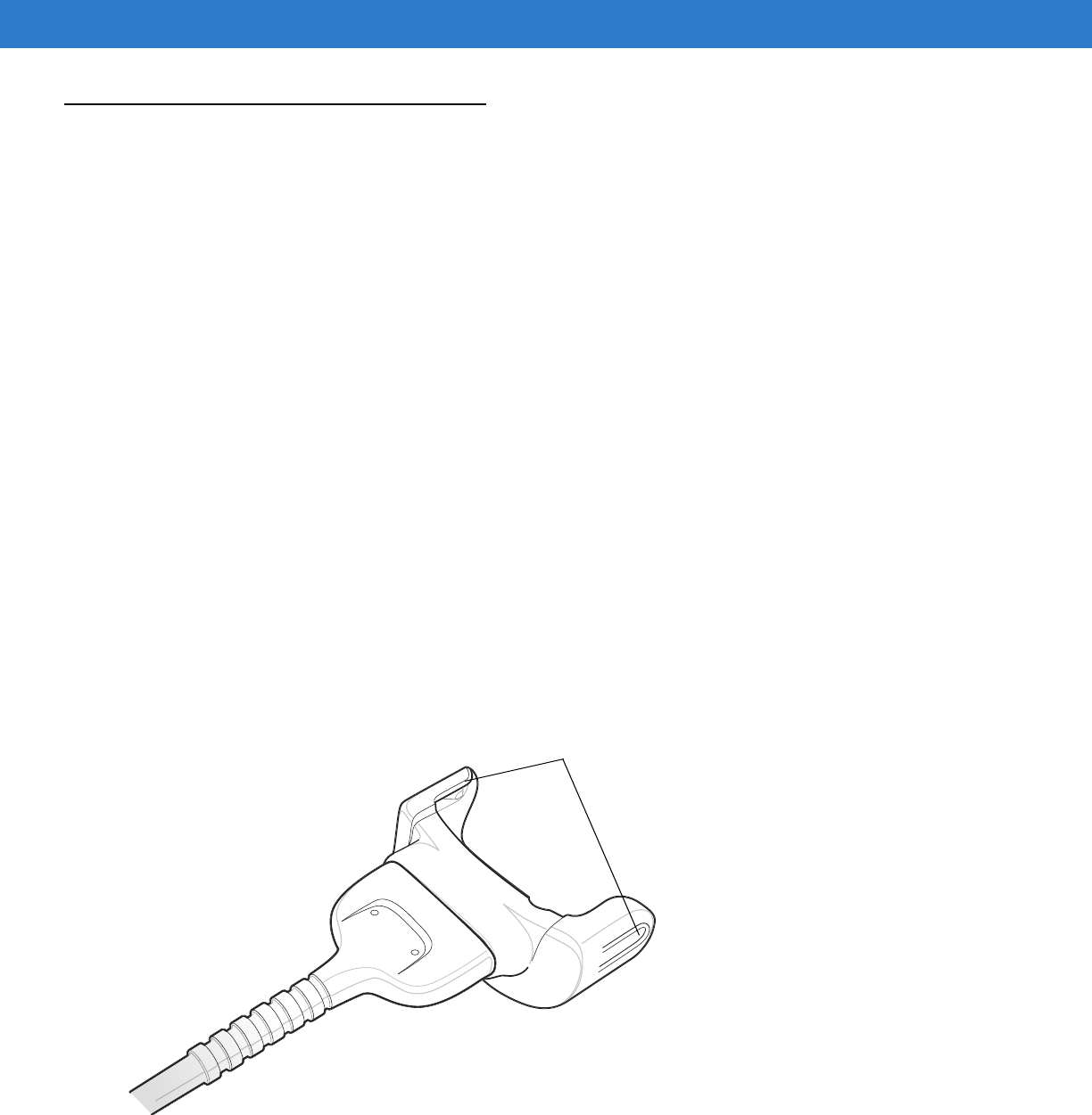
Cables
The cables are available with a variety of connection capabilities.
MC31XX Communication/Charge cables:
•
Provide the mobile computer with operating and charging power when used with the Symbol approved power
supply.
•
Synchronize information between the mobile computer and a host computer. With customized or third party
software, it can also synchronize the mobile computer with corporate databases.
•
Provide serial connection through the serial pass-through port for communication with a serial device, such
as a host computer. For communication setup procedures, refer to the MC31XX Integrator Guide.
•
Provide USB connection through the USB pass-through port for communication with a USB device, such as
a host computer. For communication setup procedures, refer to the MC31XX Integrator Guide.
The following MC31XX Communication/Charge cables are available:
•
Serial (RS232) Charge cable (9-pin D female with power input receptacle)
•
USB Client Charge cable (standard-A connector and a barrel receptacle for power).
Dedicated Printer cables, provide communication with a dedicated printer.
The following printer cables are available directly from the printer manufacturer:
•
O’Neil printer cable
•
Zebra printer cable
•
Monarch printer cable.
Figure 4-4
Cables
Snaps
Preliminary

4 - 10 MC31XX Series Mobile Computer User Guide
Battery Charging and Operating Power
The MC31XX Communication/Charge cables can charge the mobile computer battery and supply operating power.
To charge the mobile computer battery:
1. Connect the MC31XX Communication/Charge cable power input connector to the Symbol approved power
source.
2. Slide the bottom of the mobile computer into the MC31XX connector end of the MC31XX
Communication/Charge cable and gently press in until the snaps latch into the mobile computer.
3. The mobile computer amber Charge LED Indicator indicates the mobile computer battery charging status. The
Standard Battery usually charges in less than four hours and the Extended Life Battery usually charges in less
than six hours. See, Table 4-2 on page 4-5 for charging status indications.
4. When charging is complete, remove the cable by gently pulling the mobile computer and the cable apart until
the snaps release the mobile computer.
LED Charge Indications
The MC31XX Communication/Charge cables use the amber Charge LED Indicator to indicate the MC31XX battery
charging status. See, Table 4-2 on page 4-5 for charging status indications.
CAUTION Ensure that you follow the guidelines for battery safety described in Battery Safety Guidelines on page 5-2.
Preliminary
Accessories 4 - 11
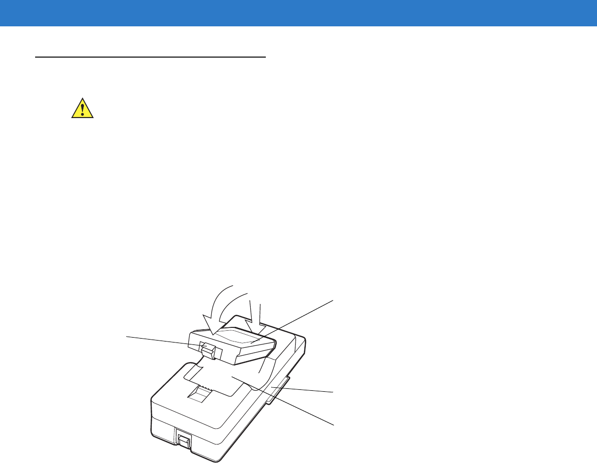
Universal Battery Charger (UBC) Adapter
The UBC Adapter can be used with a power supply as a standalone spare battery charger or it can be used with
the four station UBC2000 to simultaneously charge up to four spare batteries. For additional information on the
UBC 2000, refer to the UBC 2000 Quick Reference Guide p/n 70-33188-xx.
Spare Battery Charging
To charge spare batteries:
1. Insert the spare battery into the spare battery charging slot, bottom first.
2. Pivot the top of the battery down onto the contact pins.
Figure 4-5
UBC Adapter Battery Insertion
3. Gently press down on the battery to ensure proper contact. The Standard Battery usually charges in less than
four hours and the Extended Life Battery usually charges in less than six hours. See, Table 4-3 on page 4-12
for charging status indications.
4. When charging is complete, press the battery clip and lift the battery out of the slot.
UBC Adapter LED Charge Indications
The UBC Adapter charging LEDs indicate the battery charging status. The Standard Battery usually charges in less
than four hours and the Extended Life Battery usually charges in less than six hours.
CAUTION Ensure that you follow the guidelines for battery safety described in Battery Safety Guidelines on page 5-2.
UBC Adapter
Battery
Battery Clip
Spare Battery
Charging Slot
2
1
Preliminary
4 - 12 MC31XX Series Mobile Computer User Guide
Figure 4-6
UBC Adapter LEDs
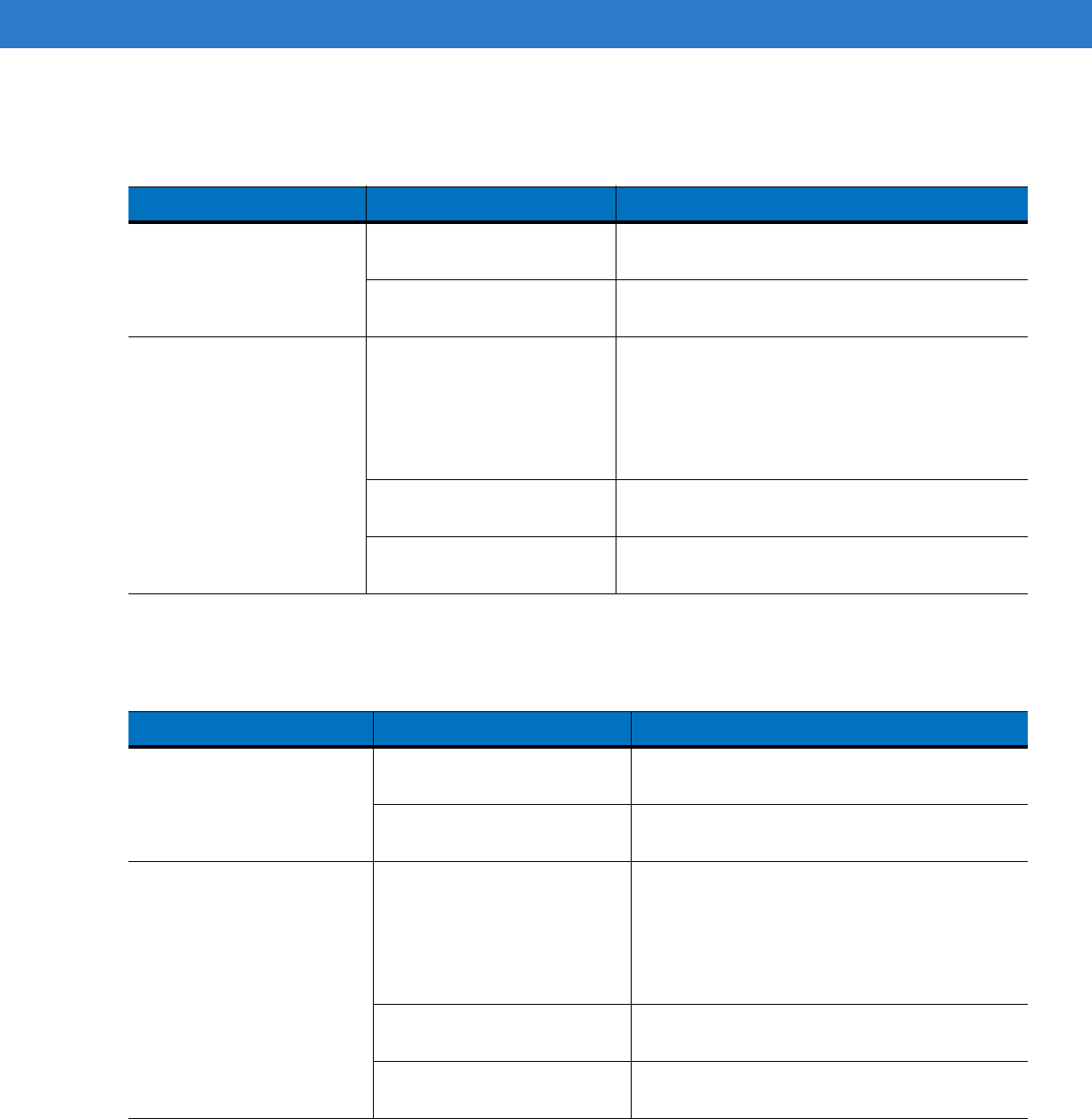
Table 4-3
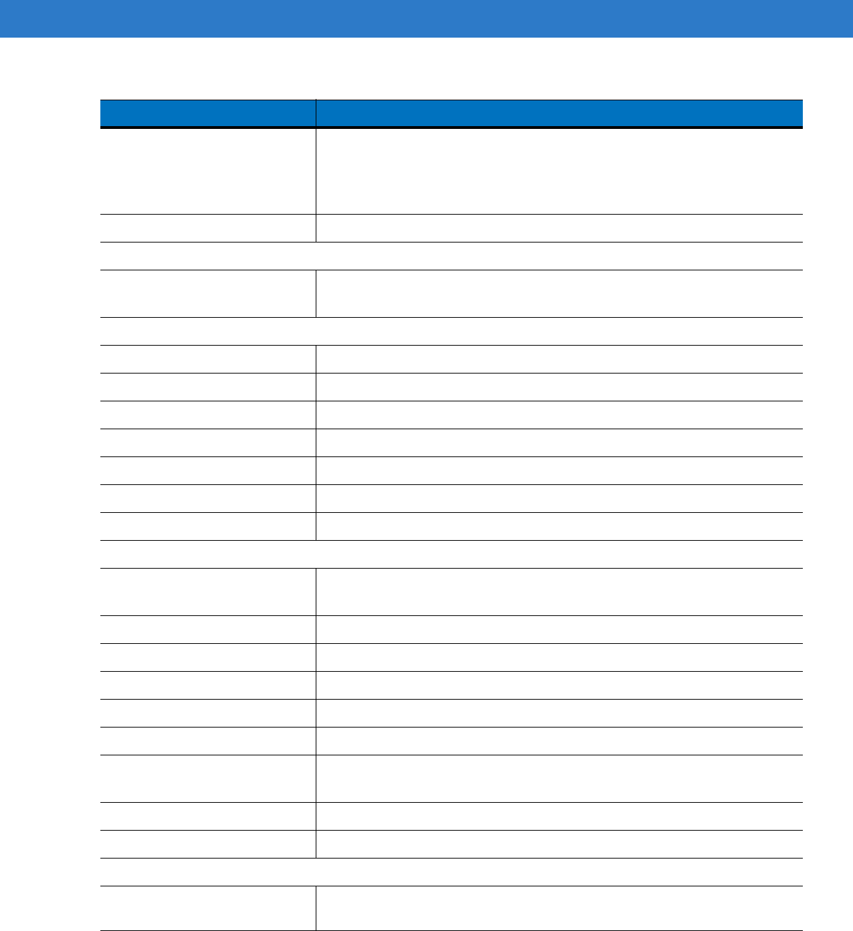
UBC Adapter Charge LED Status Indications
LED Indication Description
POWER Green Power is connected to the UBC Adapter.
READY or Green Charging complete.
STANDBY
or Flashing-Yellow The battery was deeply discharged and is being trickle charged to bring the
voltage up to the operating level. After operating level voltage is achieved, the
battery charges normally.
FAULT Yellow Charging error, check placement of mobile computer/spare battery.
CHARGING Yellow Normal charge.
POWER
READY or STANDBY or FAULT
CHARGING
(Green) (Flashing Yellow) (Solid Yellow)
(Solid Yellow)
Preliminary
Accessories 4 - 15
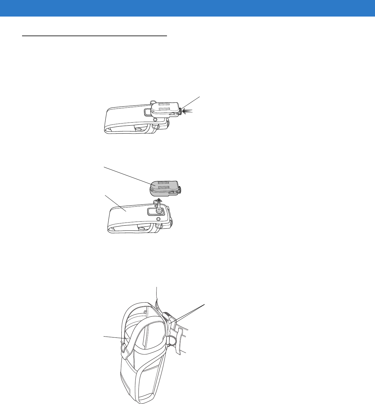
Fabric Holster
The Fabric Holster provides a soft holder for the mobile computer. It consists of a fabric mobile computer holder, a
detachable shoulder strap and a detachable belt clip. Press the release button to remove the detachable belt clip.
See Figure 4-10 to remove the detachable clip see Figure 4-11 on page 4-15 to attach the Fabric Holster to a belt
and see Figure 4-12 on page 4-16 to attach the Fabric Holster to a shoulder strap.
Figure 4-10
Fabric Holster Detachable Belt Clip
Belt Clip
Pinch the clip release and attach the Fabric Holster to a belt or waist band.
Figure 4-11
Attaching the Fabric Holster To a Belt
Detachable Belt Clip
Release Button
Mobile Computer Holder
Clip Release
Mobile Computer Holder
Preliminary
4 - 16 MC31XX Series Mobile Computer User Guide
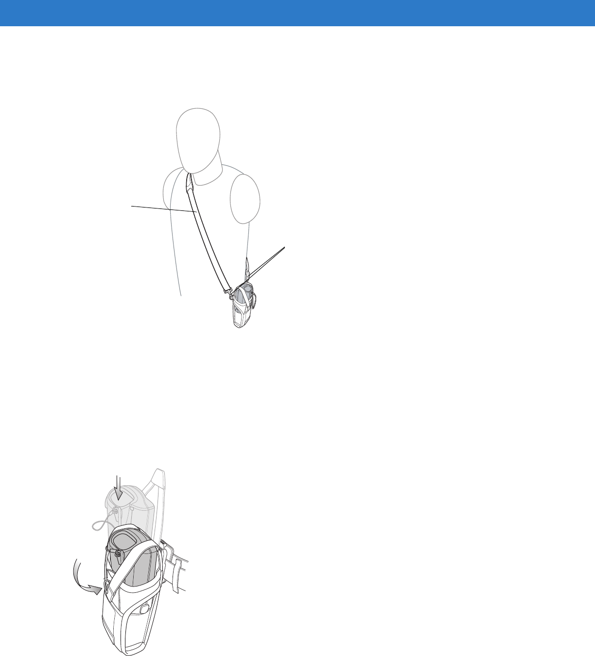
Shoulder Strap
Remove the detachable belt clip (see Figure 4-10 on page 4-15) and attach the shoulder strap.
Figure 4-12
Attach the Fabric Holster To the Shoulder Strap
The Fabric Holster holds the mobile computer on a belt or waist band.
1. To insert the mobile computer, slide the mobile computer into the Fabric Holster with the screen facing the
user.
2. Pull restraining strap over mobile computer and secure in the clip.
3. To remove the mobile computer, pull down on restraining strap to release from clip and lift retaining strap clear.
4. Lift mobile computer out of Fabric Holster.
Figure 4-13
Insert and Remove the Mobile Computer
Clip Release
Shoulder Strap
Preliminary

Chapter 5 Maintenance and Troubleshooting
Introduction
This chapter includes instructions on cleaning and storing the mobile computer, and provides troubleshooting
solutions for potential problems during mobile computer operation.
Maintaining the Mobile Computer
For trouble-free service, observe the following tips when using the mobile computer:
For trouble-free service, observe the following tips when using the MC31XX:
•
Do not scratch the screen of the MC31XX. When working with the MC31XX, use the supplied stylus or
plastic-tipped pens intended for use with a touch-sensitive screen. Never use an actual pen or pencil or other
sharp object on the surface of the MC31XX screen.
Motorola recommends using a screen protector, p/n KT-122010-01R.
•
The touch-sensitive screen of the MC31XX is glass. Do not to drop the MC31XX or subject it to strong
impact.
•
Protect the MC31XX from temperature extremes. Do not leave it on the dashboard of a car on a hot day, and
keep it away from heat sources.
•
Do not store or use the MC31XX in any location that is dusty, damp, or wet.
•
Use a soft lens cloth to clean the MC31XX. If the surface of the MC31XX screen becomes soiled, clean it
with a soft cloth moistened with a diluted window-cleaning solution.
•
Periodically replace the rechargeable battery to ensure maximum battery life and product performance.
Battery life depends on individual usage patterns.
Preliminary

5 - 2 MC31XX Series Mobile Computer User Guide
•
A screen protector is applied to the MC31XX. Motorola recommends using this to minimize wear and tear.
Screen protectors enhance the usability and durability of touch screen displays. Benefits include:
•Protection from scratches and gouges
•Durable writing and touch surface with tactile feel
•Abrasion and chemical resistance
•Glare reduction
•Keeping the device’s screen looking new
•Quick and easy installation.
Battery Safety Guidelines
•
The area in which the units are charged should be clear of debris and combustible materials or chemicals.
Particular care should be taken where the device is charged in a non commercial environment.
•
Follow battery usage, storage, and charging guidelines found in the user's guide.
•
Improper battery use may result in a fire, explosion, or other hazard.
•
To charge the mobile device battery, the battery and charger temperatures must be between +32 ºF and
+104 ºF (0 ºC and +40 ºC)
•
Do not use incompatible batteries and chargers. Use of an incompatible battery or charger may present a risk
of fire, explosion, leakage, or other hazard. If you have any questions about the compatibility of a battery or a
charger, contact Motorola Enterprise Mobility support.
•
For devices that utilize a USB port as a charging source, the device shall only be connected to products that
bear the USB-IF logo or have completed the USB-IF compliance program.
•
To enable authentication of an approved battery, as required by IEEE1725 clause 10.2.1, all batteries will
carry a Motorola hologram. Do not fit any battery without checking it has the Motorola authentication
hologram.
•
Do not disassemble or open, crush, bend or deform, puncture, or shred.
•
Severe impact from dropping any battery-operated device on a hard surface could cause the battery to
overheat.
•
Do not short circuit a battery or allow metallic or conductive objects to contact the battery terminals.
•
Do not modify or remanufacture, attempt to insert foreign objects into the battery, immerse or expose to water
or other liquids, or expose to fire, explosion, or other hazard.
•
Do not leave or store the equipment in or near areas that might get very hot, such as in a parked vehicle or
near a radiator or other heat source. Do not place battery into a microwave oven or dryer.
•
Battery usage by children should be supervised.
•
Please follow local regulations to properly dispose of used re-chargeable batteries.
•
Do not dispose of batteries in fire.
•
In the event of a battery leak, do not allow the liquid to come in contact with the skin or eyes. If contact has
been made, wash the affected area with large amounts of water and seek medical advice.
•
If you suspect damage to your equipment or battery, contact Motorola Enterprise Mobility support to arrange
for inspection.
Preliminary

Maintenance and Troubleshooting 5 - 3
Cleaning
Materials Required
•
Alcohol wipes
•
Lens tissue
•
Cotton tipped applicators
•
Isopropyl alcohol
•
Can of compressed air with a tube.
Cleaning the MC31XX
Housing
Using the alcohol wipes, wipe the housing including keys and in-between keys.
Display
The display can be wiped down with the alcohol wipes, but care should be taken not to allow any pooling of liquid
around the edges of the display. Immediately dry the display with a soft, non-abrasive cloth to prevent streaking.
Scanner Exit Window
Wipe the scanner exit window periodically with a lens tissue or other material suitable for cleaning optical material
such as eyeglasses.
Connector
1. Remove the main battery from mobile computer. See Replacing the Battery on page 1-8.
2. Dip the cotton portion of the cotton tipped applicator in isopropyl alcohol.
3. Rub the cotton portion of the cotton tipped applicator back-and-forth across the connector on the bottom of the
MC31XX. Do not leave any cotton residue on the connector.
4. Repeat at least three times.
5. Use the cotton tipped applicator dipped in alcohol to remove any grease and dirt near the connector area.
6. Use a dry cotton tipped applicator and repeat steps 4 through 6.
CAUTION Always wear eye protection.
Read warning label on compressed air and alcohol product before using.
If you have to use any other solution for medical reasons please contact Motorola for more information.
WARNING!Avoid exposing this product to contact with hot oil or other flammable liquids. If such exposure
occurs, unplug the device and clean the product immediately in accordance with these guidelines.
Preliminary

5 - 4 MC31XX Series Mobile Computer User Guide
7. Spray compressed air on the connector area by pointing the tube/nozzle about ½ inch away from the surface.
CAUTION: Do not point nozzle at yourself and others, ensure the nozzle or tube is away from your face.
8. Inspect the area for any grease or dirt, repeat if required.
Cleaning Cradle Connectors
To clean the connectors on a cradle:
1. Remove the DC power cable from the cradle.
2. Dip the cotton portion of the cotton tipped applicator in isopropyl alcohol.
3. Rub the cotton portion of the cotton tipped applicator along the pins of the connector. Slowly move the
applicator back-and-forth from one side of the connector to the other. Do not let any cotton residue on the
connector.
4. All sides of the connector should also be rubbed with the cotton tipped applicator.
5. Spray compressed air in the connector area by pointing the tube/nozzle about ½ inch away from the surface.
CAUTION: do not point nozzle at yourself and others, ensure the nozzle or tube is pointed away from your
face.
6. Ensure that there is no lint left by the cotton tipped applicator, remove lint if found.
7. If grease and other dirt can be found on other areas of the cradle, use lint free cloth and alcohol to remove.
8. Allow at least 10 to 30 minutes (depending on ambient temperature and humidity) for the alcohol to air dry
before applying power to cradle.
If the temperature is low and humidity is high, longer drying time is required. Warm temperature and dry
humidity requires less drying time.
Cleaning Frequency
The cleaning frequency is up to the customer’s discretion due to the varied environments in which the mobile
devices are used. They may be cleaned as frequently as required. However when used in dirty environments it
may be advisable to periodically clean the scanner exit window to ensure optimum scanning performance.
Preliminary
Maintenance and Troubleshooting 5 - 5
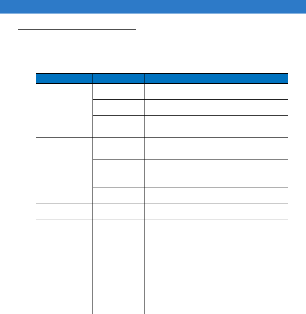
Troubleshooting
Mobile Computer
Table 5-1 Troubleshooting the Mobile Computer
Problem Cause Solution
Mobile computer does
not turn on. Main battery not
charged. Charge or replace the main battery.
Main battery not
installed properly. Ensure the battery is installed properly. See
Install Main Battery
on page 1-6
.
System crash. Perform a warm boot. If the mobile computer still does not turn
on, perform a cold boot. For more information see,
Resetting the
Mobile Computer on page 2-26
.
Battery did not charge. Battery failed. Replace battery. If the mobile computer still does not operate, try
a warm boot, then a cold boot. For more information see,
Resetting the Mobile Computer on page 2-26
.
Mobile computer
removed from cradle
while battery was
charging.
Insert mobile computer in cradle and begin charging. The
Standard Battery requires up to four hours to recharge fully and
the Extended Life Battery requires up to six hours to recharge
fully.
Extreme battery
temperature. Battery does not charge if ambient temperature is below 32°F
(0°C) or above 104°F (40°C).
Cannot see characters
on screen. Mobile computer not
powered on. Press the
Power
button.
During data
communication, no data
was transmitted, or
transmitted data was
incomplete.
Mobile computer
removed from cradle
or unplugged from
host computer during
communication.
Replace the mobile computer in the cradle, or reattach the cable
and re-transmit.
Incorrect cable
configuration. See the system administrator or refer to the MC31XX Series
Mobile Computer Integrator Guide.
Communication
software was
incorrectly installed or
configured.
See the system administrator or refer to the MC31XX Series
Mobile Computer Integrator Guide.
Mobile computer does
not emit sound. Volume setting is low
or turned off. Mobile computer may be a beeper only configuration or incorrect
setting is programmed into device.
Preliminary
5 - 6 MC31XX Series Mobile Computer User Guide
Mobile computer turns
itself off. Mobile computer is
inactive. The mobile computer turns off after a period of inactivity. This
period can be set from one to five minutes, in one-minute
intervals.
Battery is depleted. Recharge or replace the battery.
Battery is not inserted
properly. Insert the battery properly. For more information see,
Install Main
Battery on page 1-6
.
Tapping the window
buttons or icons does
not activate the
corresponding feature.
Touch screen not
calibrated correctly. Re-calibrate the screen.
From the mobile computer, Demo window double-tap the Ctl
Panel icon and double-tap on Touch Calibrate. Follow the screen
prompts.
The system crashed. Warm boot the system. To perform a warm boot, see
Resetting
the Mobile Computer on page 2-26
.
A message appears
stating that the mobile
computer memory is
full.
Too many files stored
on the mobile
computer.
Delete unused memos and records. If necessary, save these
records on the host computer.
Too many
applications installed
on the mobile
computer.
Remove unused installed applications from the mobile computer
to recover memory.
The mobile computer
does not accept scan
input.
Scanning application
is not loaded. Verify that the mobile computer is loaded with a scanning
application. See the system administrator.
Unreadable bar code. Ensure the symbol is not defaced.
Distance between
scan window and bar
code is incorrect.
Ensure the mobile computer is within proper scanning range.
Mobile computer is
not programmed for
the bar code type.
Ensure the mobile computer is programmed to accept the type of
bar code scanned.
Mobile computer is
not programmed to
generate a beep.
If a beep on a good decode is expected and a beep is not heard,
check that the application is set to generate a beep on good
decode.
Battery is low. Check the battery level. When the battery is low, the mobile
computer automatically goes into suspend mode.
Table 5-1 Troubleshooting the Mobile Computer (Continued)
Problem Cause Solution
Preliminary

Maintenance and Troubleshooting 5 - 7
Single Slot Serial/USB Cradle
Table 5-2 Troubleshooting the Single Slot Serial/USB Cradle
Symptom Possible Cause Solution
Mobile computer
amber Charge LED
Indicator does not light
when mobile computer
inserted.
Cradle is not receiving power. Ensure the power cable is connected securely to both
the cradle and to AC power.
Mobile computer is not
correctly seated. Remove and re-insert the mobile computer into the
cradle, ensuring it is correctly seated.
Spare Battery Charging
LED does not light
when spare battery is
inserted.
Spare battery is not correctly
seated. Remove and re-insert the spare battery into the charging
slot, ensuring it is correctly seated.
Mobile computer
battery is not charging. Mobile computer was
removed from cradle or cradle
was unplugged from AC
power too soon.
Ensure cradle is receiving power. Ensure the mobile
computer is seated correctly. If the mobile computer
battery is fully depleted, it can take up to four hours to
fully recharge a Standard Battery and it can take up to six
hours to fully recharge an Extended Life Battery.
Battery is faulty. Verify that other batteries charge properly. If so, replace
the faulty battery.
The mobile computer is not
fully seated in the cradle. Remove and re-insert the mobile computer into the
cradle, ensuring it is correctly seated.
Spare battery is not
charging. Battery not fully seated in
charging slot. Remove and re-insert the spare battery into the cradle,
ensuring it is correctly seated.
Battery inserted incorrectly. Ensure the contacts are facing down and toward the
back of the cradle.
Battery is faulty. Verify that other batteries charge properly. If so, replace
the faulty battery.
During data
communication, no
data was transmitted,
or transmitted data was
incomplete.
Mobile computer removed
from cradle during
communication.
Replace mobile computer in cradle and retransmit.
Incorrect cable configuration. See the system administrator or refer to the MC31XX
Series Mobile Computer Integrator Guide.
Communication software is
not installed or configured
properly.
See the system administrator or refer to the MC31XX
Series Mobile Computer Integrator Guide.
Preliminary
5 - 8 MC31XX Series Mobile Computer User Guide
Four Slot Charge Only Cradle
Four Slot Ethernet Cradle
Table 5-3 Troubleshooting the Four Slot Charge Only Cradle
Problem Cause Solution
Mobile computer amber
Charge LED Indicator does
not light when mobile
computer inserted.
Cradle is not receiving power. Ensure the power cable is connected securely to
both the cradle and to AC power.
Mobile computer is not
correctly seated. Remove and re-insert the mobile computer into the
cradle, ensuring it is correctly seated.
Mobile computer battery is
not charging. Mobile computer was
removed from cradle or cradle
was unplugged from AC
power too soon.
Ensure cradle is receiving power. Ensure the
mobile computer is seated correctly. If the mobile
computer battery is fully depleted, it can take up to
four hours to fully recharge a Standard Battery and
it can take up to six hours to fully recharge an
Extended Life Battery.
Battery is faulty. Verify that other batteries charge properly. If so,
replace the faulty battery.
The mobile computer is not
fully seated in the cradle. Remove and re-insert the mobile computer into the
cradle, ensuring it is correctly seated.
Table 5-4 Troubleshooting the Four Slot Ethernet Cradle
Problem Cause Solution
Mobile computer amber
Charge LED Indicator does
not light when mobile
computer inserted.
Cradle is not receiving power. Ensure the power cable is connected securely to
both the cradle and to AC power.
Mobile computer is not
correctly seated. Remove and re-insert the mobile computer into
the cradle, ensuring it is correctly seated.
Mobile computer battery is
not charging. Mobile computer was removed
from cradle or cradle was
unplugged from AC power too
soon.
Ensure cradle is receiving power. Ensure the
mobile computer is seated correctly. If the mobile
computer battery is fully depleted, it can take up
to four hours to fully recharge a Standard Battery
and it can take up to six hours to fully recharge an
Extended Life Battery.
Battery is faulty. Verify that other batteries charge properly. If so,
replace the faulty battery.
The mobile computer is not
fully seated in the cradle. Remove and re-insert the mobile computer into
the cradle, ensuring it is correctly seated.
Preliminary

Maintenance and Troubleshooting 5 - 9
Four Slot Spare Battery Charger
During data communication,
no data was transmitted, or
transmitted data was
incomplete.
Mobile computer removed from
cradle during communication. Replace mobile computer in cradle and
retransmit.
Incorrect cable configuration. See the system administrator or refer to the
MC31XX Series Mobile Computer Integrator
Guide.
Ethernet connection error. Link
LED is not lit (see
Link LED on
page 4-7
).
See the system administrator. Probable Ethernet
connection error.
Table 5-4 Troubleshooting the Four Slot Ethernet Cradle (Continued)
Problem Cause Solution
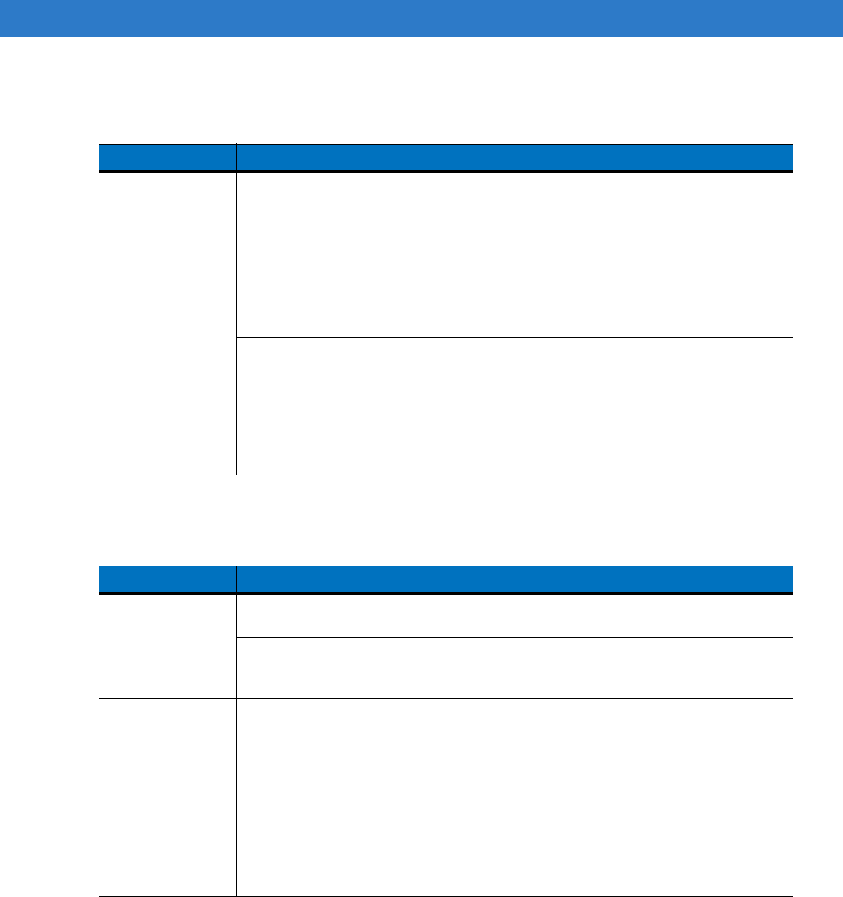
Table 5-5 Troubleshooting the Four Slot Spare Battery Charger
Symptom Possible Cause Solution
Spare Battery
Charging LED does
not light when
spare battery is
inserted.
Spare battery is not
correctly seated. Remove and re-insert the spare battery into the charging slot,
ensuring it is correctly seated.
Spare battery is not
charging. Charger is not
receiving power. Ensure the power cable is connected securely to both the charger
and to AC power.
Spare battery is not
correctly seated. Remove and re-insert the battery into the charger, ensuring it is
correctly seated.
Spare battery was
removed from charger
or charger was
unplugged from AC
power too soon.
Ensure charger is receiving power. Ensure the spare battery is
seated correctly. If a battery is fully depleted, it can take up to four
hours to fully recharge a Standard Battery and it can take up to six
hours to fully recharge an Extended Life Battery.
Spare battery is faulty. Verify that other batteries charge properly. If so, replace the faulty
battery.
Preliminary
5 - 10 MC31XX Series Mobile Computer User Guide
UBC Adapter
Cables
Table 5-6 Troubleshooting the UBC Adapter
Symptom Possible Cause Solution
Battery Charging
LED does not light
when spare battery
is inserted.
Spare battery is not
correctly seated. Remove and re-insert the spare battery into the charging slot,
ensuring it is correctly seated.
Battery not charging. Charger is not receiving
power. Ensure the power cable is connected securely to both the charger
and to AC power.
Spare battery is not
correctly seated. Remove and re-insert the spare battery into the charger, ensuring
it is correctly seated.
Spare battery was
removed from charger
or charger was
unplugged from AC
power too soon.
Ensure charger is receiving power. Ensure the spare battery is
seated correctly. If a battery is fully depleted, it can take up to four
hours to fully recharge a Standard Battery and it can take up to six
hours to fully recharge an Extended Life Battery.
Spare battery is faulty. Verify that other batteries charge properly. If so, replace the faulty
battery.
Table 5-7 Troubleshooting the Cables
Symptom Possible Cause Solution
Mobile computer
amber Charge LED
Indicator does not
light when mobile
computer attached.
Cable is not receiving
power. Ensure the power cable is connected securely to both the cable
and to AC power.
Mobile computer is not
seated correctly in the
cable.
Remove and re-attach the mobile computer to the MC31XX
connector, ensuring it is correctly seated.
Mobile computer
battery is not
charging.
Mobile computer was
detached from cable or
cable was unplugged
from AC power too
soon.
Ensure cable is receiving power. Ensure the mobile computer is
seated correctly. If the mobile computer battery is fully depleted, it
can take up to four hours to fully recharge a Standard Battery and
it can take up to six hours to fully recharge an Extended Life
Battery.
Battery is faulty. Verify that other batteries charge properly. If so, replace the faulty
battery.
The mobile computer is
not fully seated in the
cable.
Remove and re-attach the mobile computer to the cable, ensuring
it is correctly seated.
Preliminary

Maintenance and Troubleshooting 5 - 11
During data
communication, no
data was
transmitted, or
transmitted data was
incomplete.
Cable removed from
mobile computer during
communication.
Reattach cable to mobile computer and retransmit.
Incorrect cable
configuration. See the system administrator or refer to the MC31XX Series
Mobile Computer Integrator Guide.
Communication
software is not installed
or configured properly.
See the system administrator or refer to the MC31XX Series
Mobile Computer Integrator Guide.
Table 5-7 Troubleshooting the Cables (Continued)
Symptom Possible Cause Solution
Preliminary

Appendix A Technical Specifications
Mobile Computer and Accessory Technical Specifications
Table A-1 summarizes the mobile computer technical specifications and intended operating environments.
Table A-2 summarizes the accessory technical specifications and the intended operating environments.
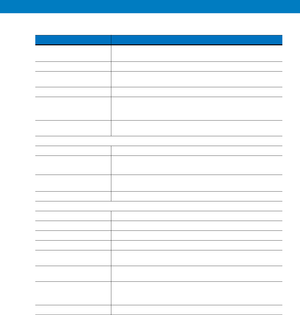
Table A-1
MC31XX Technical Specifications
ItemDescription
Physical Characteristics
Dimensions MC31XXS:
7.49 in L x 3.25 in W x 1.77 in D
(190.4 mm L x 82.6 mm W x 45.2 mm D)
At grip: 2.40 in. W x 1.44 in. D/61.2 mm x 36.8 mm
MC31XXR:
8.36 in L x 3.25 in W x 1.57 in D
(212.5 mm L x 82.6 mm W x 39.9 mm D)
At grip: 2.40 in. W x 1.14 in. D/61.2 mm x 29 mm
MC3190G:
7.5 in L x 3.1 in W x 6.5 in D
(193 mm L x 80.8 mm W x 166 mm H)
Weight (including battery,
stylus,and handstrap) MC31XXR (with standard battery)* - 13.4 oz (380 g)
MC31XXS (with extended battery)* - 14.8 oz (420 g)
MC3190G (with extended battery)* - 18.34 oz (520 g)
Display 3.0 inch Color (TFT) (320 x 320) Display with backlight
Touch Panel Polycarbonate analog resistive touch
Backlight LED backlight
Preliminary
A - 2 MC3000 User Guide
Battery Standard: Rechargeable Lithium-Ion 2740 mAh(3.7V) (for MC31XXR )
Extended Life: Rechargeable Lithium-Ion 4400 mAh(3.7V)(for MC31XXS,MC3190G)
Expansion SlotUser accessible (located under battery); approved for memory expansion only
Network ConnectionsHigh-speed USB client, full-speed USB host, Bluetooth and WiFi.
USB host mode available with appropriate cables only.
Notification Programmable LEDs; Audio notifications
Keypad Options28-key Numeric Telephony
38-key Shifted Alpha (calculator-style integrated numeric keypad)
48-key Alpha-Numeric (calculator-style integrated numeric keypad)
Audio Speaker, receiver, microphone, software support for full duplex capability,
Bluetooth stereo.
Performance Characteristics
CPU Marvell PXA320 processor at 624 MHz
Operating SystemMicrosoft
®
Windows CE.NET 6.0 Professional
Microsoft
®
Windows Mobile 6.1 Classic
Memory 128 MB RAM/256MB Flash or
128 MB RAM/512 MB Flash
Output Power USB: 5 VDC @ 200 mA max.
User Environment
Operating Temperature -20°C to 50°C (-4°F to 122°F)
Storage Temperature -20° to 50°C (-4° to 122°F)
Charging Temperature 0° C to 40° C (32°F to 104°F)
Humidity 95% non-condensing
Drop Specification Meets and exceeds MIL-STD 810F drop specifications: 4 ft./1.2 m drop to
concrete across the operating temperature range
Tumble500 1.64 ft./0.5 m tumbles (1,000 drops) at room temperature; meets and
exceeds applicable MIL-STD 810F tumble specifications
Electrostatic Discharge (ESD)+/-15 kV air discharge
+/- 8 kV direct discharge
+/- 8 kV indirect discharge
Sealing IP54 category 2
Table A-1
MC31XX Technical Specifications (Continued)
ItemDescription
Technical Specifications A - 3
Wireless LAN Data and Voice Communications
Wireless Local Area Network
(WLAN) radio Tri-mode IEEE
®
802.11a/b/g
Data Rates Supported 1, 2, 5.5, 6, 9, 11, 12, 18, 24, 36, 48, and 54 Mbps
Operating Channels Chan 1-13 (2412-2472 MHz), Chan 14 (2484 MHz) Japan only; actual
operating channels/frequencies depend on regulatory rules and certification
agency
Security WPA2 (Personal or Enterprise); 802.1x; EAP-TLS; TTLS (CHAP,
MS-CHAP, MS-CHAPv2, PAP or MD5); PEAP (TLS, MSCHAPv2,
EAP-GTC); LEAP, EAP-FAST (TLS, MS-CHAPv2,
EAP-GTC); CCXv4 certified; support for IPv6; FIPS140-2 Certified
Spreading Technique Direct Sequence Spread Spectrum (DSSS) and Orthogonal Frequency Division
Multiplexing (OFDM)
Antenna Internal antenna w/diversity
Voice Communication Voice-over-IP ready, Wi-Fi™-certified, IEEE 802.11a/b/g direct sequence
wireless LAN, Wi-Fi Multimedia™ (WMM), Motorola Voice Quality Manager
(VQM)
Wireless PAN Data and Voice Communications
Bluetooth Class II, v2.1 with Enhanced Data Rate (EDR); integrated antenna
Regulatory
Electrical Safety Certified to UL60950, CSA C22.2No. 60950, EN60950/IEC 950
Environmental RoHS-compliant
WLAN and Bluetooth (PAN)
USA:
FCC Part 15.247, 15.407
Canada:
RSS-210
EU:
EN 300 328, EN 301 893
Japan:
ARIB STD T33, T66, T70, T71
Australia:
AS/NZS 4268s
RF Exposure
USA:
FCC Part 2, FCC OET Bulletin 65 Supplement C
Canada:
RSS-102
EU:
EN 50360
Australia:
Radio communications Standard 2003
EMI/RFI Radio Version
North America:
FCC Part 2 (SAR), FCC Part 15, RSS210 Class B, EN 301
489-1, 489-17
Table A-1
MC31XX Technical Specifications (Continued)
Item Description
Preliminary
A - 4 MC3000 User Guide
EMI/RFI Batch Version
North America:
FCC Part 15, ICES 003 Class B
EU:
EN55022 Class B EN55024
Japan:
CISPR 22, Class B
Australia:
AS3548
Laser Safety IEC Class2/FDA Class II in accordance with IEC60825-1/EN60825-1
Data Capture Specifications
Options 1D laser scanner
2D imager
Linear 1D Scanner (SE950) Specifications
Optical Resolution 0.004 in. minimum element width
Roll +/- 35° from vertical
Pitch Angle +/- 65° from normal
Skew Tolerance +/- 50° from normal
Ambient Light 10,000 ft. candles/107,640 lux
Scan Rate 104 (+/- 12) scans/sec (bidirectional)
Scan Angle 47° ± 3° default; configurable narrow angle: 35° ± 3°
2D Imager Engine (SE4500) Specifications
Field of View Horizontal - 32.2°
Vertical - 24.5°
Optical Resolution 752 x 480 pixels
Roll 360°
Pitch Angle +/- 60° from normal
Skew Tolerance +/- 60° from normal
Ambient Light 9,000 ft. candles (96,900 Lux)
Focal Distance from Front of
Engine Near: 1.6 inches
Far: 15 inches
Aiming Element (VLD) 655 nm +/- 10 nm
Illumination Element (LED) 625 nm +/- 5 nm
Motorola Interactive Sensor Technology
Motion-sensor 3-axis accelerometer that enables motion-sensing applications on dynamic
screen orientation, power management and free-fall detects
Table A-1
MC31XX Technical Specifications (Continued)
Item Description
Preliminary

Technical Specifications A - 5
Table A-2
Accessory Specifications
Single Slot
Serial/USB
Cradle
Cables
Four Slot Charge
Only and
Ethernet Cradles
Four Slot
Spare Battery
Charger
Universal
Battery Charger
(UBC) Adapter
Operating
Temperature 32° to 122°F (0° to +50°C) 32° to 104°F (0° to +40°C)
Storage Temperature -40° to 158°F (-40° to 70°C)
Battery Charging
Temperature
32° to 104° F (0° to +40° C) ambient temperature
Humidity 5% to 95% non-condensing
Size (L x D x H) 4.4 in x 5.7 in x 4.7
in
(11.2 cm x 14.5 cm
x 12 cm)
6 feet
(1.83
m)
18 in x 4 in x 5 in
(45.7 cm x 10.1 cm
x 12 cm)
8.25 in x 6.0 in
x 1.7 in (20.96
cm x 15.24 cm
x 4.32 cm)
2.5 in x 6.1 in x 1.5
in
(6.4 cm x 15.5 cm
x 3.8 cm)
Weight 0.60 lbs (0.27 kg) N/A Charge only:
2.25 lbs (1.02 kg)
Ethernet:
2.38 lbs (1.08 kg)
13.6 oz (386 g) 0.25 lbs (0.11 kg)
Power 12V, 3.3 A 5.4V, 3
A12V, 9 A 12V, 3.3 A 15V, 1.5 A
Drop 30 inches (76.2 centimeter) to vinyl covered concrete
Electrostatic
Discharge (ESD) +/-15 kV air discharge, +/- 8 kV direct discharge, +/- 8 kV indirect discharge
Preliminary

A - 6 MC3000 User Guide
Preliminary

Appendix B Keypads
Introduction
The mobile computer is available with the following keypad configurations:
•
28-key keypad
•
38-key keypad
•
48-key keypad.
NOTE For information about using the soft keyboard input panel. For more information, see Entering Information
Using the Keyboard Input Panel on page 2-15.
Preliminary
B - 2 MC31XX Series Mobile Computer User Guide
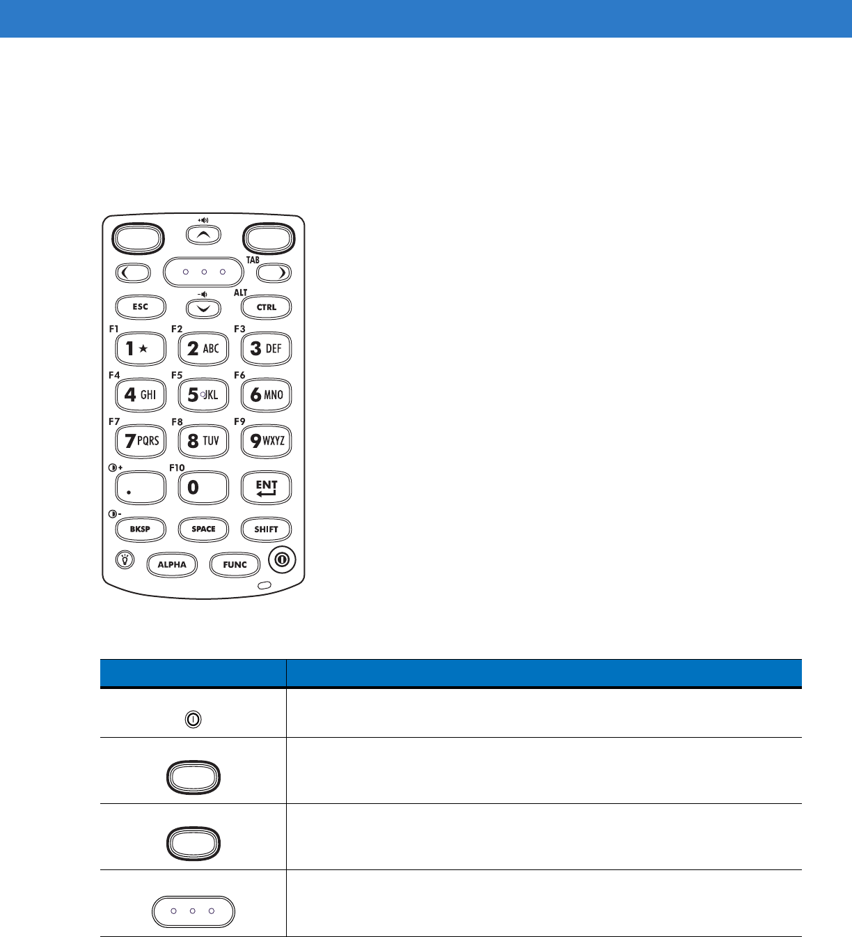
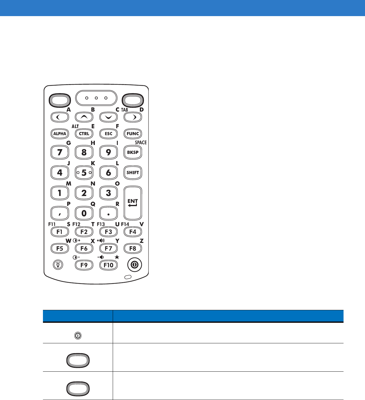
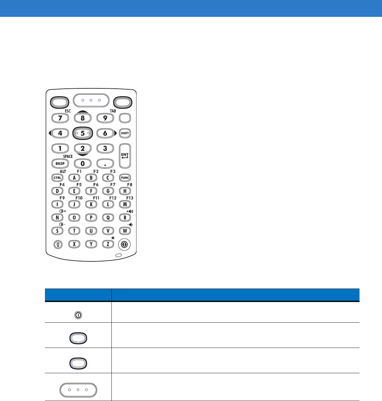
28-Key Keypad
The 28-key keypad contains a Power button, application keys, scroll keys and function keys. The keypad is
color-coded to indicate the alternate function key (blue) values and the alternate ALPHA key (orange) values. Note
that keypad functions can be changed by an application so the mobile computer keypad may not function as
described. See Table B-1 on page B-2 for key and button descriptions and Table B-8 on page B-14 for the keypad
special functions.
Figure B-1
28-Key Keypad
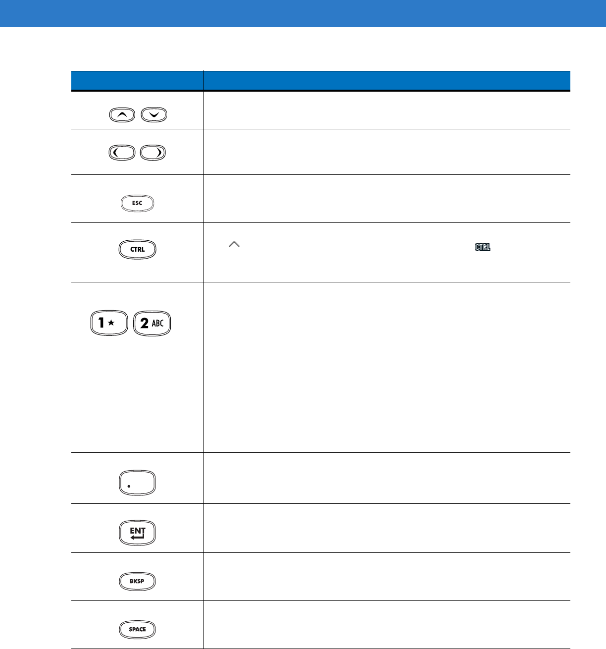
Table B-1
28-Key Descriptions
Key Description
Power (red) Powers the mobile computer screen on and off (resume and suspend).
Green Circle Programmable application function key by default.
Red Circle Programmable application function key by default.
Scan (yellow) Used in scanning applications, press to scan a bar code. This key has the same
function as activating the side mounted scan buttons.
Preliminary
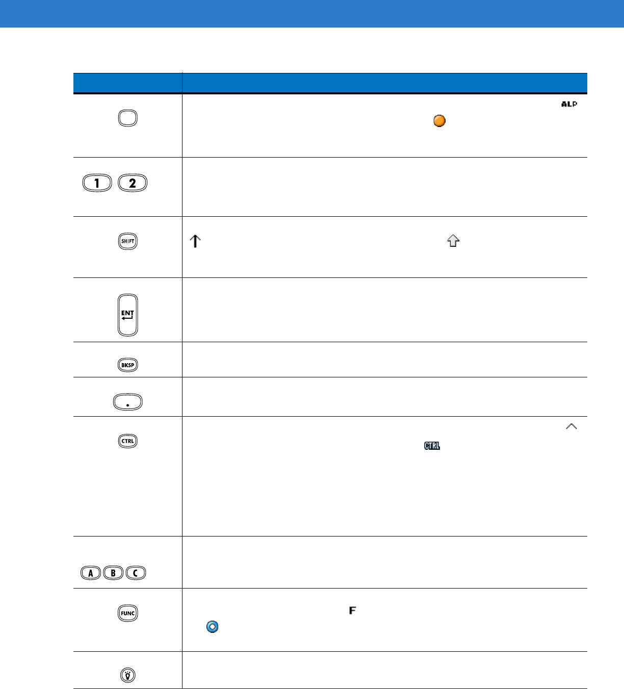
Keypads B - 3
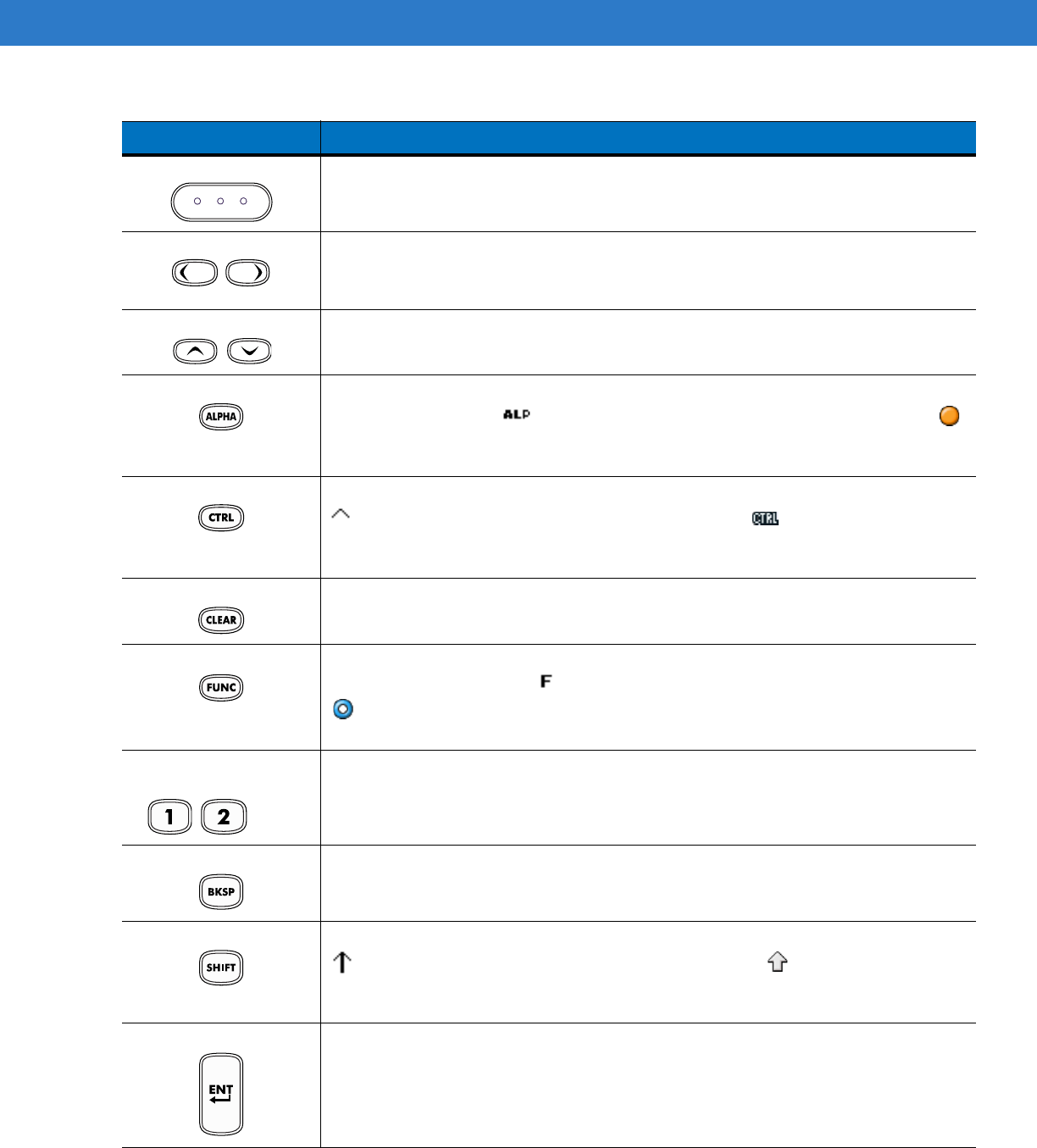
Scroll Up and Down Moves up and down from one item to another. Increases/decreases specified
values.
Scroll Left and Right Moves left and right from one item to another. Increases/decreases specified values.
Produces a
TAB
when the blue
FUNC
key is activated and the right arrow key is
pressed.
ESC Produces the
ESC
function by default.
CTRL Press and release the CTRL key to activate the keypad alternate CTRL functions.
The icon appears on the taskbar on WinCE devices or the icon appears at
the bottom of the screen on Windows Mobile 6.1 devices. Press and release the
CTRL key again to return to the default keypad functions.
Numeric/Alpha/Special
Function Numeric, alpha or special function keys. Numeric by default.
Produces a special function when the blue
FUNC
key is activated.
Produces alpha values when the orange
ALPHA
key is activated.
In Alpha state, produces the lower case alphabetic characters on the key. Each key
press produces the next alphabetic character in sequence. For example, press and
release the
ALPHA
key and then press the
4
key once to produce the letter ‘g’; press
and release the
ALPHA
key and then press the
4
key three times to produce the
letter ‘i’.
When the
SHIFT
key is pressed in Alpha state, the upper case alphabetic characters
on the key are produced. For example, press and release the
ALPHA
key, press and
hold the
SHIFT
key and then press the
4
key once to produce the letter ‘G’; press
and release the
ALPHA
key, press and hold the
SHIFT
key and then press the
4
key
three times to produce the letter ‘I’.
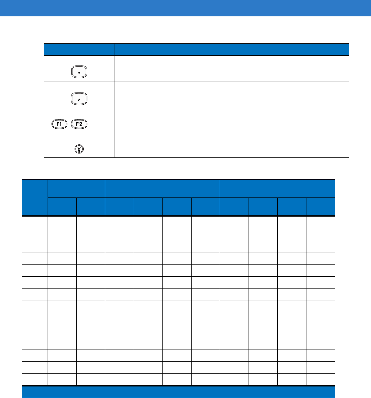
Period/Decimal Point Produces a period for alpha entries and a decimal point for numeric entries by
default.
Produces the
F10
function when the blue
FUNC
key is activated.
Enter Executes a selected item or function.
BKSP
BKSP
, backspace function by default.
SPACE
SPACE
, space function by default.
Table B-1
28-Key Descriptions (Continued)
Key Description
Preliminary
B - 4 MC31XX Series Mobile Computer User Guide
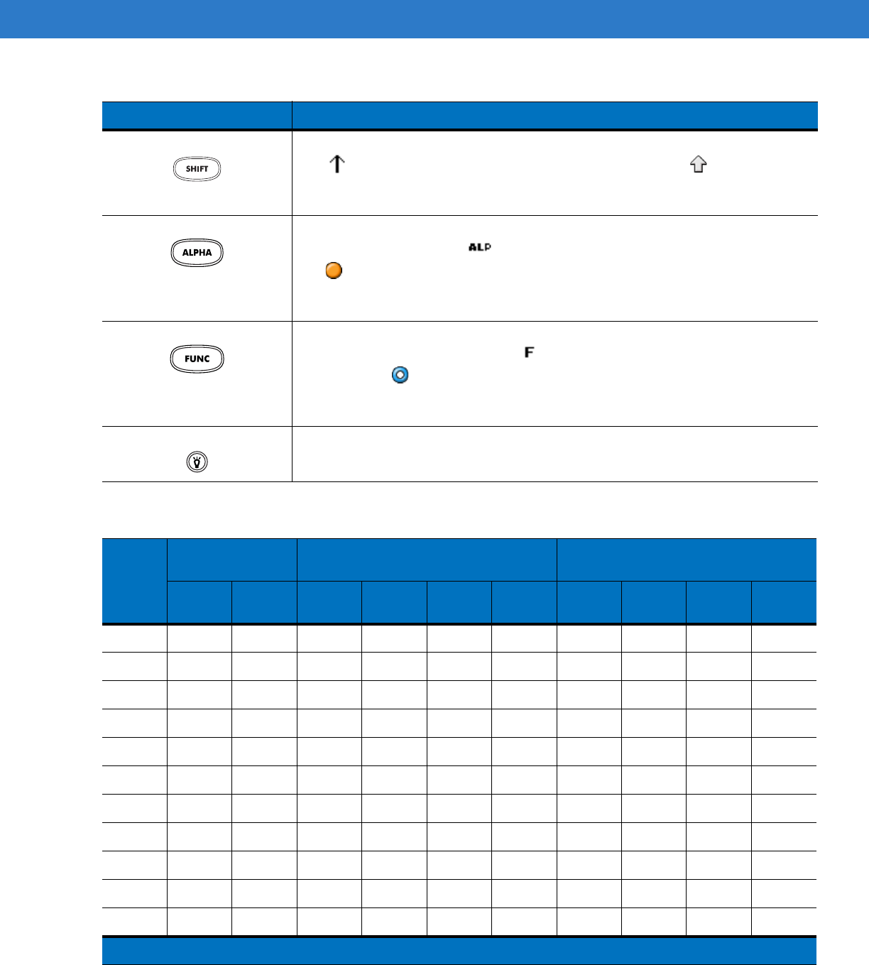
Shift Press and release the
SHIFT
key to activate the keypad alternate SHIFT functions.
The icon appears on the taskbar on WinCE devices and the icon appears at
the bottom of the screen on Windows Mobile 6.1 devices. Press and release the
SHIFT
key again to return to the default keypad functions.
ALPHA (orange) Press the orange
ALPHA
key to access the alternate
ALPHA
characters (shown on
the keypad in orange). The icon appears on the taskbar on WinCE devices and
the icon appears at the bottom of the screen on Windows Mobile 6.1 devices.
Press and release the orange
ALPHA
key again to return to the default keypad
functions.
FUNC (blue) Press and release the blue
FUNC
key to activate the keypad alternate functions
(shown on the keypad in blue). The icon appears on the taskbar on WinCE
devices or the icon appears at the bottom of the screen on Windows Mobile 6.1
devices. Press and release the blue
FUNC
key again to return to the default keypad
functions.
Display backlight
Toggles the display backlight on and off.
Table B-2
28 Key Keypad Input Modes
Key
Numeric Mode Orange Key
(Alpha Lowercase Mode)
Orange + Shift Keys
(Alpha Uppercase Mode)
SHIFT
+ Key
1st
Press
2nd
Press
3rd
Press
4th
Press
1st
Press
2nd
Press
3rd
Press
4th
Press
1 1 ! @? @?
22@abc ABC
33#def DEF
44$ghi GHI
55%j kl JKL
66^mno MNO
77&pqr sPQRS
88* t uv TUV
99( wxyzWXYZ
00) .au au
,,<, ,
Note: An application can change the key functions. The keypad may not function exactly as described.
Table B-1
28-Key Descriptions (Continued)
Key Description
Preliminary

Keypads B - 5
..>. .
**** *
--_- _
Table B-2
28 Key Keypad Input Modes (Continued)
Key
Numeric Mode Orange Key
(Alpha Lowercase Mode)
Orange + Shift Keys
(Alpha Uppercase Mode)
SHIFT
+ Key
1st
Press
2nd
Press
3rd
Press
4th
Press
1st
Press
2nd
Press
3rd
Press
4th
Press
Note: An application can change the key functions. The keypad may not function exactly as described.
Preliminary
B - 6 MC31XX Series Mobile Computer User Guide
38-Key Keypad
The 38-key keypad contains a Power button, application keys, scroll keys and function keys. The keypad is
color-coded to indicate the alternate function key (blue) values. Note that keypad functions can be changed by an
application so the mobile computer keypad may not function as described. See Table B-3 on page B-6 for key and
button descriptions and Table B-8 on page B-14 for the keypad special functions.
Figure B-2
38-Key Keypad
Table B-3
38-Key Descriptions
Key Description
Power (red) Powers the mobile computer screen on and off (resume and suspend).
Green Circle Programmable application function key by default.
Red Circle Programmable application function key.
Preliminary
Keypads B - 7
Scan (yellow) Used in scanning applications, press to scan a bar code.
Scroll Left and Right Moves left and right from one item to another by default.
Produces a
TAB
when the blue
FUNC
key is activated and the right arrow key is
pressed.
Scroll Up and Down Moves up and down from one item to another by default.
ALPHA (orange) Press the orange
ALPHA
key to access the alternate
ALPHA
characters (shown on the
keypad in orange). The icon appears on the taskbar on WinCE devices and the
icon appears at the bottom of the screen on Windows Mobile 6.1 devices. Press and
release the orange
ALPHA
key again to return to the default keypad functions.
CTRL Press and release the
CTRL
key to activate the keypad alternate
CTRL
functions. The
icon appears on the taskbar on WinCE devices or the icon appears at the
bottom of the screen on Windows Mobile 6.1 devices. Press and release the
CTRL
key
again to return to the default keypad functions.
CLEAR Clears inputs.
FUNC (blue) Press and release the blue
FUNC
key to activate the keypad alternate functions (shown
on the keypad in blue). The icon appears on the taskbar on WinCE devices or the
icon appears at the bottom of the screen on Windows Mobile 6.1 devices. Press and
release the blue
FUNC
key again to return to the default keypad functions.
Numeric/Alpha/Special
Function Press for the default numeric value.
Produces alpha values when the orange
ALPHA
key is activated.
BKSP/SPACE
BKSP
, backspace function by default.
Produces the
SPACE
function when the orange
ALPHA
key is activated.
SHIFT Press and release the
SHIFT
key to activate the keypad alternate
SHIFT
functions. The
icon appears on the taskbar on WinCE devices and the icon appears at the
bottom of the screen on Windows Mobile 6.1 devices. Press and release the
SHIFT
key
again to return to the default keypad functions.
Enter Executes a selected item or function.
Table B-3
38-Key Descriptions (Continued)
Key Description
...
Preliminary
B - 8 MC31XX Series Mobile Computer User Guide
Period/Decimal Point Produces a period for alpha entries and a decimal point for numeric entries.
Produces alpha values when the orange
ALPHA
key is activated.
Comma Produces a comma by default.
Produces alpha values when the orange
ALPHA
key is activated.
Special Function/Alpha Special function by default or when the blue
FUNC
key is activated.
Produces alpha values when the orange
ALPHA
key is activated.
Display backlight Toggles the display backlight on and off.
Table B-3
38-Key Descriptions (Continued)
Key Description
...
Table B-4
Telephony Numeric Keypad Input Modes
Key
Numeric Mode Orange Key
(Alpha Lowercase Mode)
Orange + Shift Keys
(Alpha Uppercase Mode)
SHIFT +
Key
1st
Press
2nd
Press
3rd
Press
4th
Press
1st
Press
2nd
Press
3rd
Press
4th
Press
11 ! @? @?
22@abc ABC
33#def DEF
44$ghi GHI
55%j kl JKL
66 ^ m n o M N O
77&pqr sPQRS
88 * t u v T U V
99( wxyzWXYZ
00 ) .au au
,, < , ,
.. > . .
**** *
-- _ - _
Note: An application can change the key functions. The keypad may not function exactly as described.
Preliminary
Keypads B - 9
48-Key Keypad
The 48-key keypad contains a Power button, application keys, scroll keys and function keys. The keypad is
color-coded to indicate the alternate function key (blue) values. Note, that keypad functions can be changed by an
application so the mobile computer keypad may not function as described. See Table B-3 on page B-6 for key and
button descriptions and Table B-8 on page B-14 for the keypad special functions.
Figure B-3
48-Key Keypad
Table B-5
48-Key Descriptions
Key Description
Power (red) Powers the mobile computer screen on and off (resume and suspend).
Green Circle Unassigned application function key by default.
Red Circle Unassigned application function key.
Scan (yellow) Scan key, used for scanning applications.
Preliminary
B - 10 MC31XX Series Mobile Computer User Guide
Orange Press the orange key to access the alternate navigation and selection functions. The
icon appears on the taskbar on WinCE devices and the icon appears at the bottom of
the screen on Windows Mobile 6.1 devices. Press and release the orange key again to
return to the default keypad functions.
Numeric/Scroll/Select Numeric, scroll, select keys. Numeric by default.
With the orange key activated, the
2
,
4
,
6
, and
8
keys produce scroll functions and the
5
key produces a select function. With the
FUNC
key activated,
7
produces the
ESC
function
and
9
produces the
TAB
function.
Shift Press and release the
SHIFT
key to activate the keypad alternate
SHIFT
functions. The
icon appears on the taskbar on WinCE devices and the icon appears at the bottom
of the screen on Windows Mobile 6.1 device. Press and release the
SHIFT
key again to
return to the default keypad functions.
Enter Executes a selected item or function.
BKSP/SPACE
BKSP
, backspace function by default.
Produces the
SPACE
function when the blue
FUNC
key is activated.
Period/Decimal Point Produces a period for alpha entries and a decimal point for numeric entries.
Control Press and release the
CTRL
key to activate the keypad alternate
CTRL
functions. The
icon appears on the taskbar on WinCE devices or the icon appears at the bottom of
the screen on Windows Mobile 6.1 devices. Press and release the
CTRL
key again to
return to the default keypad functions.
Press and release the blue
FUNC
key and then the
CTRL
key to activate the
ALT
functions. The icon appears on the taskbar on WinCE devices or the icon appears
at the bottom of the screen on Windows Mobile 6.1 devices. Press and release the
CTRL
key two times to return to the default keypad functions.
Alpha/Special
Function Alpha by default.
Special function by default when the blue
FUNC
key is activated.
FUNC (blue) Press and release the blue
FUNC
function key to activate the keypad alternate functions
(shown on the keypad in blue). The icon appears on the taskbar on WinCE devices or
the icon appears at the bottom of the screen on Windows Mobile 6.1 devices. Press
and release the blue
FUNC
function key again to return to the default keypad functions.
Display Backlight Toggles the display backlight on and off.
Table B-5
48-Key Descriptions (Continued)
Key Description
...
ALT
ALT
...
Preliminary

Keypads B - 11
The MC95XX offers four types modular keypad configurations:
•
Alpha Primary
•
Alpha Numeric Wide
•
Calculator Numeric
•
Telephony Numeric.
Table B-6
Alpha Primary Keypad Input Modes
Key Normal Shift + Key Orange + Key
AaA
BbB1
Cc C2
Dd D3
EeE
Ff F4
Gg G5
Hh H6
IiI
Jj J7
Kk K8
Ll L9
MmM
Nn N*
Oo O0
PpP#
Qq Q
Rr Rau
Ss S@
Tt T/
Uu T?
Vv V
Ww W
Xx X
Note: An application can change the key functions. The keypad may not function exactly as described.
Preliminary

B - 12 MC31XX Series Mobile Computer User Guide
Yy Y
ZzZ
ENTER Enter Enter Enter
TAB Tab Tab Back tab
SPACE Space Space Space
BKSP Backspace Backspace Backspace
Table B-6
Alpha Primary Keypad Input Modes (Continued)
Key Normal Shift + Key Orange + Key
Note: An application can change the key functions. The keypad may not function exactly as described.
Preliminary
Keypads B - 13
Keypad Special Functions
The keypad special functions are color coded on the keypads. For example, on the 38-key keypad, the display
contrast icon is blue indicating that the blue function key must be selected first along with the F6 key, to increase
the display contrast.
Keypads
The mobile computer is available with one of three keypads:
•
28-key keypad
•
38-key keypad
•
48-key keypad.
The keypads can be selected as necessary to support specialized applications. The 28, 38 and 48-key keypads
contain a Power button, application keys, scroll keys and function keys. The keypads are color-coded to indicate
the alternate function key (blue) values and the alternate ALPHA key (orange) values. See Table B-8 for the
special character generation. Characters can also be generated using the keyboard input panel. For more
information see, Entering Information Using the Keyboard Input Panel on page 2-15.
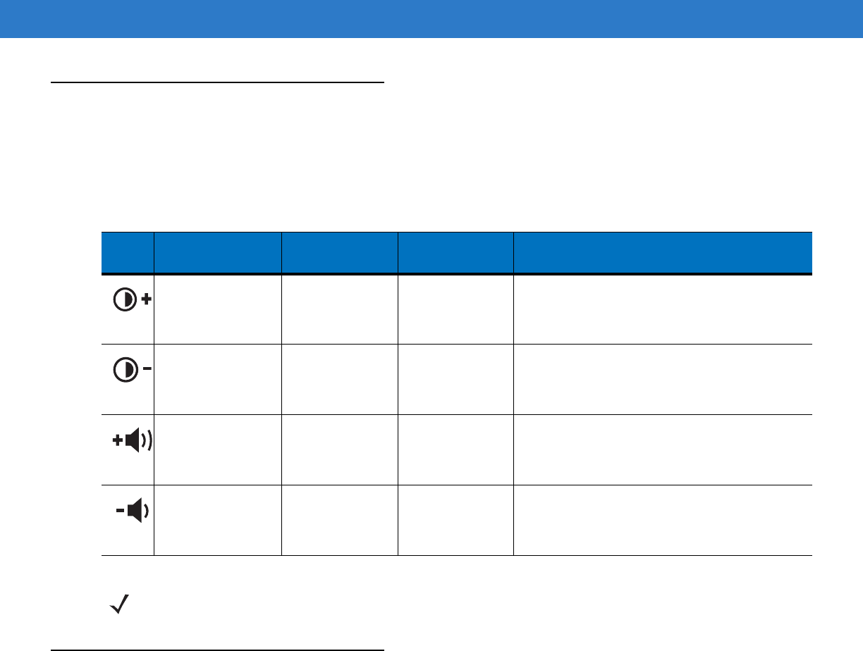
Table B-7
Keypad Special Functions
Icon 28-Key
Keystrokes
38-Key
Keystrokes
48-Key
Keystrokes Special Function
Blue function key
and
period
.Blue function
key and
F6
Blue function
key and
N
Increases display contrast setting, darkens the
display (on monochrome units only).
Blue function key
and
BKSP
.Blue function
key and
F9
Blue function
key and
S
Decreases display contrast setting, lightens the
display (on monochrome units only).
Blue function key
and the up arrow. Blue function
key and
F7
Blue function
key and
R
Increases scan decode beeper volume.
Blue function key
and down arrow. Blue function
key and
F10
Blue function
key and
W
Decreases scan decode beeper volume.
NOTE Mobile computers with color screens do not have contrast settings.
Preliminary

B - 14 MC31XX Series Mobile Computer User Guide
Table B-8
Special Character Generation Map
Special
Character
28-Key Keypad Key
Sequence, Special
Character Generation
38-Key Keypad Key
Sequence, Special
Character Generation
48-Key Keypad Key
Sequence, Special
Character Generation
[ Use the Keyboard Input
Panel* FUNC + 4 FUNC + T
] Use the Keyboard Input
Panel* FUNC + 5 FUNC + U
/ Use the Keyboard Input
Panel* FUNC + 9 FUNC + Q
\ Use the Keyboard Input
Panel* FUNC + 3 Use the Keyboard Input
Panel*
= Use the Keyboard Input
Panel* FUNC + 8 FUNC + P
; Use the Keyboard Input
Panel* FUNC + 6 FUNC + V
- Use the Keyboard Input
Panel* FUNC + 7 FUNC + O
` Use the Keyboard Input
Panel* FUNC + 2 FUNC + Y
“ Use the Keyboard Input
Panel* SHIFT + FUNC + 1 Use the Keyboard Input
Panel*
! SHIFT + 1 SHIFT + 1 SHIFT + 1
@ SHIFT + 2 SHIFT + 2 SHIFT + 2
# SHIFT + 3 SHIFT + 3 SHIFT + 3
$ SHIFT + 4 SHIFT + 4 SHIFT + 4
% SHIFT + 5 SHIFT + 5 SHIFT + 5
^ SHIFT + 6 SHIFT + 6 SHIFT + 6
& SHIFT + 7 SHIFT + 7 SHIFT + 7
* SHIFT + 8 SHIFT + 8 SHIFT + 8
( SHIFT + 9 SHIFT + 9 or FUNC + SHIFT
+ 9 SHIFT + 9
) SHIFT + 0 SHIFT + 0 or FUNC + SHIFT
+ 0 SHIFT + 0
‘ Use the Keyboard Input
Panel* FUNC + 1 FUNC + X
* See
Entering Information Using the Keyboard Input Panel on page 2-15
.
Preliminary

Keypads B - 15
“ Use the Keyboard Input
Panel* Use the Keyboard Input
Panel* Use the Keyboard Input
Panel*
+ Use the Keyboard Input
Panel* SHIFT + FUNC + 8 Use the Keyboard Input
Panel*
: Use the Keyboard Input
Panel* SHIFT + FUNC + 6 Use the Keyboard Input
Panel*
< Use the Keyboard Input
Panel* FUNC + SHIFT +
,
Use the Keyboard Input
Panel*
> Use the Keyboard Input
Panel* FUNC + SHIFT +
.
SHIFT +
.
? Use the Keyboard Input
Panel* SHIFT + FUNC + 9 Use the Keyboard Input
Panel*
_ Use the Keyboard Input
Panel* SHIFT + FUNC + 7 Use the Keyboard Input
Panel*
{ Use the Keyboard Input
Panel* SHIFT + FUNC + 4 Use the Keyboard Input
Panel*
} Use the Keyboard Input
Panel* SHIFT + FUNC + 5 Use the Keyboard Input
Panel*
~ Use the Keyboard Input
Panel* SHIFT + FUNC + 2 Use the Keyboard Input
Panel*
| N/A SHIFT + FUNC + 3 N/A
Table B-8
Special Character Generation Map (Continued)
Special
Character
28-Key Keypad Key
Sequence, Special
Character Generation
38-Key Keypad Key
Sequence, Special
Character Generation
48-Key Keypad Key
Sequence, Special
Character Generation
* See
Entering Information Using the Keyboard Input Panel on page 2-15
.
Preliminary

B - 16 MC31XX Series Mobile Computer User Guide
Preliminary

Glossary
Numeric
802.11/802.11abg. A radio protocol that may be used by the WLAN radio card.
A
Access Point. Access Point (AP) refers to Motorola’s Ethernet Access Point. It is a piece of communications equipment that
manages communications between the host computer system and one or more wireless terminals. An AP connects to
a wired Ethernet LAN and acts as a bridge between the Ethernet wired network and IEEE 802.11 interoperable
radio-equipped mobile units, such as a mobile computer. The AP allows a mobile user to roam freely through a facility
while maintaining a seamless connection to the wired network.
AirBEAM® Manager. AirBEAM® Manager is a comprehensive wireless network management system that provides
essential functions that are required to configure, monitor, upgrade and troubleshoot the wireless network and its
components (including networked mobile computers). Some features include event notification, access point
configuration, diagnostics, statistical reports, auto-discovery, wireless proxy agents and monitoring of access points and
mobile units.
AirBEAM® Smart Client. AirBEAM® Smart Client is part of Motorola’s AirBEAM® suite, which also includes AirBEAM®
Safe and AirBEAM® Manager. The AirBEAM® Smart Client system uses the network accessible host server to store
software files that are to be downloaded to the mobile computers. The AirBEAM® Smart Client provides the mobile
computers with the “smarts” to request software from the host. It allows them to request, download and install software,
as well as to upload files and status data. The AirBEAM® Smart Client uses the industry standard FTP or TFTP file
transfer protocols to check the host system for updates, and if necessary, to transfer updated software. Most often,
AirBEAM® Smart Client is used with wireless networks, but any TCP/IP connection can be used. For more information,
refer to the AirBEAM® Smart Windows® CE Client Product Reference Guide (p/n 72-63060-xx).
AP. See Access Point.
Aperture. The opening in an optical system defined by a lens or baffle that establishes the field of view.
ASCII. American Standard Code for Information Interchange. A 7 bit-plus-parity code representing 128 letters, numerals,
punctuation marks and control characters. It is a standard data transmission code in the U.S.
Preliminary

Glossary - 2 MC31XX Series Mobile Computer User Guide
B
Bar. The dark element in a printed bar code symbol.
Bar Code. A pattern of variable-width bars and spaces which represents numeric or alphanumeric data in machine-readable
form. The general format of a bar code symbol consists of a leading margin, start character, data or message character,
check character (if any), stop character, and trailing margin. Within this framework, each recognizable symbology uses
its own unique format. See Symbology.
Bar Code Density. The number of characters represented per unit of measurement (e.g., characters per inch).
Bar Height. The dimension of a bar measured perpendicular to the bar width.
Bar Width. Thickness of a bar measured from the edge closest to the symbol start character to the trailing edge of the same
bar.
Bit. Binary digit. One bit is the basic unit of binary information. Generally, eight consecutive bits compose one byte of data.
The pattern of 0 and 1 values within the byte determines its meaning.
Bits per Second (bps). Bits transmitted or received.
Bit. Binary digit. One bit is the basic unit of binary information. Generally, eight consecutive bits compose one byte of data.
The pattern of 0 and 1 values within the byte determines its meaning.
bps. See Bits Per Second.
Byte. On an addressable boundary, eight adjacent binary digits (0 and 1) combined in a pattern to represent a specific
character or numeric value. Bits are numbered from the right, 0 through 7, with bit 0 the low-order bit. One byte in
memory is used to store one ASCII character.
boot or boot-up. The process a computer goes through when it starts. During boot-up, the computer can run self-diagnostic
tests and configure hardware and software.
C
CDRH. Center for Devices and Radiological Health. A federal agency responsible for regulating laser product safety. This
agency specifies various laser operation classes based on power output during operation.
CDRH Class 1. This is the lowest power CDRH laser classification. This class is considered intrinsically safe, even if all laser
output were directed into the eye's pupil. There are no special operating procedures for this class.
CDRH Class 2. No additional software mechanisms are needed to conform to this limit. Laser operation in this class poses
no danger for unintentional direct human exposure.
Character. A pattern of bars and spaces which either directly represents data or indicates a control function, such as a
number, letter, punctuation mark, or communications control contained in a message.
Character Set. Those characters available for encoding in a particular bar code symbology.
Preliminary

Glossary - 3
Check Digit. A digit used to verify a correct symbol decode. The scanner inserts the decoded data into an arithmetic formula
and checks that the resulting number matches the encoded check digit. Check digits are required for UPC but are
optional for other symbologies. Using check digits decreases the chance of substitution errors when a symbol is
decoded.
Codabar. A discrete self-checking code with a character set consisting of digits 0 to 9 and six additional characters: (“-”, “$”,
“:”, “/”, “,”, and “+”).
Code 128. A high density symbology which allows the controller to encode all 128 ASCII characters without adding extra
symbol elements.
Code 3 of 9 (Code 39). A versatile and widely used alphanumeric bar code symbology with a set of 43 character types,
including all uppercase letters, numerals from 0 to 9 and 7 special characters (“-”, “.”, “/”, “+”, “%”, “$” and space). The
code name is derived from the fact that 3 of 9 elements representing a character are wide, while the remaining 6 are
narrow.
Code 93. An industrial symbology compatible with Code 39 but offering a full character ASCII set and a higher coding
density than Code 39.
Code Length. Number of data characters in a bar code between the start and stop characters, not including those
characters.
Cold Boot. A cold boot restarts the mobile computer and erases all user stored records and entries.
COM port. Communication port; ports are identified by number, e.g., COM1, COM2.
Continuous Code. A bar code or symbol in which all spaces within the symbol are parts of characters. There are no
intercharacter gaps in a continuous code. The absence of gaps allows for greater information density.
Cradle. A cradle is used for charging the terminal battery and for communicating with a host computer, and provides a
storage place for the terminal when not in use.
D
Dead Zone. An area within a scanner's field of view, in which specular reflection may prevent a successful decode.
Decode. To recognize a bar code symbology (e.g., UPC/EAN) and then analyze the content of the specific bar code
scanned.
Decode Algorithm. A decoding scheme that converts pulse widths into data representation of the letters or numbers
encoded within a bar code symbol.
Decryption. Decryption is the decoding and unscrambling of received encrypted data. Also see, Encryption and Key.
Depth of Field. The range between minimum and maximum distances at which a scanner can read a symbol with a certain
minimum element width.
Discrete Code. A bar code or symbol in which the spaces between characters (intercharacter gaps) are not part of the code.
Preliminary

Glossary - 4 MC31XX Series Mobile Computer User Guide
Discrete 2 of 5. A binary bar code symbology representing each character by a group of five bars, two of which are wide.
The location of wide bars in the group determines which character is encoded; spaces are insignificant. Only numeric
characters (0 to 9) and START/STOP characters may be encoded.
E
EAN. European Article Number. This European/International version of the UPC provides its own coding format and
symbology standards. Element dimensions are specified metrically. EAN is used primarily in retail.
Element. Generic term for a bar or space.
EMDK. Enterprise Mobility Developer’s Kit.
Encoded Area. Total linear dimension occupied by all characters of a code pattern, including start/stop characters and data.
ESD. Electro-Static Discharge
ESN. Electronic Serial Number. The unique hardware number associated with a cellular device, which is transmitted to the
system when the device communicates with the cellular system.
Ethernet. Ethernet communication port. Allows a wired interface to a radio network.
F
Flash Memory. Flash memory is nonvolatile, semi-permanent storage that can be electronically erased in the circuit and
reprogrammed. Mobile computers may use Flash memory to store the operating system (ROM-DOS), the terminal
emulators, and the Citrix ICA Client for DOS.
FTP. See File Transfer Protocol.
Flash Memory. Flash memory is responsible for storing the system firmware and is non-volatile. If the system power is
interrupted the data is not be lost.
G
Gateway Address. An IP address for a network gateway or router. A mobile computer may be part of a subnet as specified
by its IP address and Netmask. It can send packets directly to any node on the same subnet. If the destination node is
on a different subnet, then the terminal sends the packet to the gateway first. The gateway determines how to route the
packet to the destination subnet. This field is an option used by networks that require gateways.
H
Hard Reset. See Cold Boot.
Preliminary

Glossary - 5
Hz. Hertz; A unit of frequency equal to one cycle per second.
Host Computer. A computer that serves other terminals in a network, providing such services as computation, database
access, supervisory programs and network control.
I
IEC. International Electrotechnical Commission. This international agency regulates laser safety by specifying various laser
operation classes based on power output during operation.
IEC (825) Class 1. This is the lowest power IEC laser classification. Conformity is ensured through a software restriction of
120 seconds of laser operation within any 1000 second window and an automatic laser shutdown if the scanner's
oscillating mirror fails.
Interleaved 2 of 5. A binary bar code symbology representing character pairs in groups of five bars and five interleaved
spaces. Interleaving provides for greater information density. The location of wide elements (bar/spaces) within each
group determines which characters are encoded. This continuous code type uses no intercharacter spaces. Only
numeric (0 to 9) and START/STOP characters may be encoded.
imaging scanning . Mobile computers with an integrated imager use digital camera technology to take a digital picture of
a bar code, store the resulting image in memory and execute state-of-the-art software decoding algorithms to extract
the data from the image.
Intercharacter Gap. The space between two adjacent bar code characters in a discrete code.
Interleaved Bar Code. A bar code in which characters are paired together, using bars to represent the first character and
the intervening spaces to represent the second.
Interleaved 2 of 5. A binary bar code symbology representing character pairs in groups of five bars and five interleaved
spaces. Interleaving provides for greater information density. The location of wide elements (bar/spaces) within each
group determines which characters are encoded. This continuous code type uses no intercharacter spaces. Only
numeric (0 to 9) and START/STOP characters may be encoded.
IP. Internet Protocol. The IP part of the TCP/IP communications protocol. IP implements the network layer (layer 3) of the
protocol, which contains a network address and is used to route a message to a different network or subnetwork. IP
accepts “packets” from the layer 4 transport protocol (TCP or UDP), adds its own header to it and delivers a “datagram”
to the layer 2 data link protocol. It may also break the packet into fragments to support the maximum transmission unit
(MTU) of the network.
IP Address. (Internet Protocol address) The address of a computer attached to an IP network. Every client and server
station must have a unique IP address. A 32-bit address used by a computer on a IP network. Client workstations have
either a permanent address or one that is dynamically assigned to them each session. IP addresses are written as four
sets of numbers separated by periods; for example, 204.171.64.2.
L
LAN. Local area network. A radio network that supports data communication within a local area, such as within a warehouse
of building.
Preliminary

Glossary - 6 MC31XX Series Mobile Computer User Guide
laser scanner. A type of bar code reader that uses a beam of laser light.
LASER. Light Amplification by Stimulated Emission of Radiation.The laser is an intense light source. Light from a laser is
all the same frequency, unlike the output of an incandescent bulb. Laser light is typically coherent and has a high energy
density.
Laser Diode. A gallium-arsenide semiconductor type of laser connected to a power source to generate a laser beam. This
laser type is a compact source of coherent light.
LED Indicator. A semiconductor diode (LED - Light Emitting Diode) used as an indicator, often in digital displays. The
semiconductor uses applied voltage to produce light of a certain frequency determined by the semiconductor's particular
chemical composition.
Light Emitting Diode. See LED.
M
MC. Mobile Computer.
MIL. 1 mil = 1 thousandth of an inch.
MIN. Mobile Identification Number. The unique account number associated with a cellular device. It is broadcast by the
cellular device when accessing the cellular system.
Misread (Misdecode). A condition which occurs when the data output of a reader or interface controller does not agree with
the data encoded within a bar code symbol.
Mobile Computer. In this text, mobile computer refers to the Symbol portable computer. It can be set up to run as a
stand-alone device, or it can be set up to communicate with a network, using wireless radio technology.
N
Nominal. The exact (or ideal) intended value for a specified parameter. Tolerances are specified as positive and negative
deviations from this value.
Nominal Size. Standard size for a bar code symbol. Most UPC/EAN codes are used over a range of magnifications (e.g.,
from 0.80 to 2.00 of nominal).
NVM. Non-Volatile Memory.
P
Parameter. A variable that can have different values assigned to it.
PDT. Portable Data Terminal.
Preliminary

Glossary - 7
Percent Decode. The average probability that a single scan of a bar code would result in a successful decode. In a
well-designed bar code scanning system, that probability should approach near 100%.
Q
Quiet Zone. A clear space, containing no dark marks, which precedes the start character of a bar code symbol and follows
the stop character.
R
RAM. Random Access Memory. Data in RAM can be accessed in random order, and quickly written and read.
Reflectance. Amount of light returned from an illuminated surface.
Resolution. The narrowest element dimension which is distinguished by a particular reading device or printed with a
particular device or method.
RF. Radio Frequency.
ROM. Read-Only Memory. Data stored in ROM cannot be changed or removed.
Router. A device that connects networks and supports the required protocols for packet filtering. Routers are typically used
to extend the range of cabling and to organize the topology of a network into subnets. See Subnet.
RS232. An Electronic Industries Association (EIA) standard that defines the connector, connector pins, and signals used to
transfer data serially from one device to another.
S
Scan Area. Area intended to contain a symbol.
Scanner. An electronic device used to scan bar code symbols and produce a digitized pattern that corresponds to the bars
and spaces of the symbol. Its three main components are:
1. Light source (laser or photoelectric cell) - illuminates a bar code.
2. Photodetector - registers the difference in reflected light (more light reflected from spaces).
3. Signal conditioning circuit - transforms optical detector output into a digitized bar pattern.
Scanning Mode. The scanner is energized, programmed and ready to read a bar code.
Scanning Sequence. A method of programming or configuring parameters for a bar code reading system by scanning bar
code menus.
SDK. Software Development Kit
Preliminary

Glossary - 8 MC31XX Series Mobile Computer User Guide
Self-Checking Code. A symbology that uses a checking algorithm to detect encoding errors within the characters of a bar
code symbol.
Shared Key. Shared Key authentication is an algorithm where both the AP and the MU share an authentication key.
SID. System Identification code. An identifier issued by the FCC for each market. It is also broadcast by the cellular carriers
to allow cellular devices to distinguish between the home and roaming service.
Soft Reset. See Warm Boot.
Space. The lighter element of a bar code formed by the background between bars.
Specular Reflection. The mirror-like direct reflection of light from a surface, which can cause difficulty decoding a bar code.
Spring Radio Protocol. A radio protocol that may be used by the Symbol radio card. Symbol Radio cards that use the
Spring protocol also have an Net ID.
Start/Stop Character. A pattern of bars and spaces that provides the scanner with start and stop reading instructions and
scanning direction. The start and stop characters are normally to the left and right margins of a horizontal code.
Subnet. A subset of nodes on a network that are serviced by the same router. See Router.
Subnet Mask. A 32-bit number used to separate the network and host sections of an IP address. A custom subnet mask
subdivides an IP network into smaller subsections. The mask is a binary pattern that is matched up with the IP address
to turn part of the host ID address field into a field for subnets. Default is often 255.255.255.0.
Substrate. A foundation material on which a substance or image is placed.
SVTP. Symbol Virtual Terminal Program.
Symbol. A scannable unit that encodes data within the conventions of a certain symbology, usually including start/stop
characters, quiet zones, data characters and check characters.
Symbol Aspect Ratio. The ratio of symbol height to symbol width.
Symbol Height. The distance between the outside edges of the quiet zones of the first row and the last row.
Symbol Length. Length of symbol measured from the beginning of the quiet zone (margin) adjacent to the start character
to the end of the quiet zone (margin) adjacent to a stop character.
Symbology. The structural rules and conventions for representing data within a particular bar code type (e.g. UPC/EAN,
Code 39, PDF417, etc.).
T
Tolerance. Allowable deviation from the nominal bar or space width.
Preliminary

Glossary - 9
U
UPC. Universal Product Code. A relatively complex numeric symbology. Each character consists of two bars and two
spaces, each of which is any of four widths. The standard symbology for retail food packages in the United States.
V
Visible Laser Diode (VLD). A solid state device which produces visible laser light.
W
WAN. Wide-Area Network. A radio network that supports data communication beyond a local area. That is, information can
be sent across a city, state, or even nationwide.
Warm Boot. A warm boot restarts the mobile computer by closing all running programs. All data that is not saved to flash
memory is lost.
Wireless Local Area Network (WLAN). See LAN.
Wireless Wide Area Network (WWAN). See WAN.
WNMP. (Wireless Network Management Protocol) This is Symbol’s proprietary MAC layer protocol used for inter access
point communication and other MAC layer communication.
Preliminary

Glossary - 10 MC31XX Series Mobile Computer User Guide
Preliminary

Index
Numerics
28-key keypad . . . . . . . . . . . . . . . . . . . . . . . . . B-2, B-13
2-D bar codes . . . . . . . . . . . . . . . . . . . . . . . . . . . . . 2-22
38-key keypad . . . . . . . . . . . . . . . . . . . . . . . . . B-6, B-13
48-key keypad . . . . . . . . . . . . . . . . . . . . . . . . . B-9, B-13
A
accessories . . . . . . . . . . . . . . . . . . . . . . . . . . . . . . . . 1-1
cables . . . . . . . . . . . . . . . . . . . . . . . . . . . . . . . . . 4-9
four slot charge only cradle . . . . . . . . . . . . . . . . . 4-6
LED indicators . . . . . . . . . . . . . . . . . . . . . . . 4-6
four slot cradles
battery charging . . . . . . . . . . . . . . . . . . . . . . 4-6
four slot spare battery charger
battery charging . . . . . . . . . . . . . . . . . . . . . . 4-8
LED indicators . . . . . . . . . . . . . . . . . . . . . . . 4-8
MC3000 communication/charge cables
battery charging . . . . . . . . . . . . . . . . . . . . . 4-10
LED indicators . . . . . . . . . . . . . . . . . . . . . . 4-10
plastic holster . . . . . . . . . . . . . . . . . . . . . .4-13, 4-15
SD card . . . . . . . . . . . . . . . . . . . . . . . . . . . . . . . . 1-5
single slot serial/USB cradle . . . . . . . . . . . . . . . . 4-3
battery charging . . . . . . . . . . . . . . . . . . . . . . 4-3
LED indicators . . . . . . . . . . . . . . . . . . . . . . . 4-4
stylus . . . . . . . . . . . . . . . . . . . . . . . . . . . . . . . . . . 4-2
UBC adapter
battery charging . . . . . . . . . . . . . . . . . . . . . 4-11
LED indicators . . . . . . . . . . . . . . . . . . . . . . 4-11
active and indicate programs . . . . . . . . . . . . . . . . . . . 2-2
active tasks . . . . . . . . . . . . . . . . . . . . . . . . . . . . . . . . 2-5
ActiveSync . . . . . . . . . . . . . . . . . . . . . . . . . . . . . . . . . .xvi
icon . . . . . . . . . . . . . . . . . . . . . . . . . . . . . . . . . . . 2-9
adaptive frequency hopping . . . . . . . . . . . . . . . . . . . 3-1
AFH . . . . . . . . . . . . . . . . . . . . . . . . . . . . . . . . . . . . . . 3-1
attaching strap/door assembly . . . . . . . . . . . . . . . . . 1-13
B
bar codes
two dimensional . . . . . . . . . . . . . . . . . . . . . . . . 2-22
battery
charging . . . . . . . . . . . . . . . . . . . . . . . . . . . . . . . 1-8
temperature range . . . . . . . . . . . . . . . . . . . . A-5
install . . . . . . . . . . . . . . . . . . . . . . . . . . . . . . . . . 1-6
status . . . . . . . . . . . . . . . . . . . . . . . . . . . . . . . . . 2-2
battery charge status . . . . . . . . . . . . . . . . . . . . . . . . . 2-2
battery chargers
four slot spare battery charger
battery charging . . . . . . . . . . . . . . . . . . . . . . 4-8
LED indicators . . . . . . . . . . . . . . . . . . . . . . . 4-8
MC3000 communication/charge cables
battery charging . . . . . . . . . . . . . . . . . . . . . 4-10
LED indicators . . . . . . . . . . . . . . . . . . . . . . 4-10
UBC adapter
battery charging . . . . . . . . . . . . . . . . . . . . . 4-11
LED indicators . . . . . . . . . . . . . . . . . . . . . . 4-11
battery charging . . . . . . . . . . . . . . . . . . . . . . . . . . . . 1-8
backup battery . . . . . . . . . . . . . . . . . . . . . . . . . . 1-8
four slot cradles . . . . . . . . . . . . . . . . . . . . . . . . . 4-6
four slot spare battery charger . . . . . . . . . . . . . . 4-8
main battery . . . . . . . . . . . . . . . . . . . . . . . . . . . . 1-8
MC3000 communication/charge cables . . . . . . 4-10
battery charging . . . . . . . . . . . . . . . . . . . . . 4-10
temperature range . . . . . . . . . . . . . . . . . . . . . . . 1-8
UBC adapter . . . . . . . . . . . . . . . . . . . . . . . . . . . 4-11
battery status . . . . . . . . . . . . . . . . . . . . . . . . . . . . 2-2, 2-3
beeper . . . . . . . . . . . . . . . . . . . . . . . . . . . . . . . . . . . . 1-2
beeper volume . . . . . . . . . . . . . . . . . . . . . . . . . . . . B-13
Bluetooth . . . . . . . . . . . . . . . . . . . . . . . . . . . . . . . . . . 3-1
adaptive frequency hopping . . . . . . . . . . . . . . . . 3-1
bonding . . . . . . . . . . . . . . . . . . . . . . . . . . . . . . . 3-38
deleting bonded device . . . . . . . . . . . . . . . . . . . 3-39
security . . . . . . . . . . . . . . . . . . . . . . . . . . . . . . . . 3-2
Preliminary

Index - 2 MC31XX Series Mobile Computer User Guide
turning off . . . . . . . . . . . . . . . . . . . . . 3-5, 3-14, 3-21
turning on . . . . . . . . . . . . . . . . . . . . . 3-5, 3-14, 3-21
bluetooth
communicating icon . . . . . . . . . . . . . . . . . . . . . . 2-9
disabled icon . . . . . . . . . . . . . . . . . . . . . . . . . . . . 2-8
discovering devices . . . . . . . . . . . . . . 3-6, 3-15, 3-22
enabled icon . . . . . . . . . . . . . . . . . . . . . . . . . . . . 2-8
icon . . . . . . . . . . . . . . . . . . . . . . . . . . . . . . . . . . . 2-3
turning on and off . . . . . . . . . . . . . . . 3-5, 3-14, 3-21
bonding
Bluetooth . . . . . . . . . . . . . . . . . . . . . . . . . . . . . . 3-38
bootcold . . . . . . . . . . . . . . . . . . . . . . . . . . . . . . .2-27, 3-4
warm . . . . . . . . . . . . . . . . . . . . . . . . . . . . . .2-27, 3-4
bullets . . . . . . . . . . . . . . . . . . . . . . . . . . . . . . . . . . . . . xv
C
calibration screen . . . . . . . . . . . . . . . . . . . . . . . . . . 1-10
characters, special . . . . . . . . . . . . . . . . . . . . . . . . . . B-14
charge battery . . . . . . . . . . . . . . . . . . . . . . . . . . . . . . 1-8
charge LED indicator . . . . . . . . . . . . . . . . . . . . . .1-2, 1-4
charging
spare batteries . . . . . . . . . . . . . . . . . . . . . . . . . . 1-9
temperature range . . . . . . . . . . . . . . . . . . . . . . . A-5
charging battery . . . . . . . . . . . . . . . . . . . . . . . . . . . . . 1-8
charging, temperature range . . . . . . . . . . . . . . . . . . . 1-8
cleaning . . . . . . . . . . . . . . . . . . . . . . . . . . . . . . . . . . . 5-1
clock, display . . . . . . . . . . . . . . . . . . . . . . . . . . . . . . . 2-6
cold boot . . . . . . . . . . . . . . . . . . . . . . . . . . . . . .2-27, 3-4
command bar . . . . . . . . . . . . . . . . . . . . . . . . . . . . . . . 2-8
icons . . . . . . . . . . . . . . . . . . . . . . . . . . . . . . .2-7, 2-8
command bar icons . . . . . . . . . . . . . . . . . . . . . . . . . . 2-8
communication status . . . . . . . . . . . . . . . . . . . . . . . . 2-2
configuration . . . . . . . . . . . . . . . . . . . . . . . . . . . . . . . . xii
contrast settings . . . . . . . . . . . . . . . . . . . . . . . . . . . B-13
conventions
notational . . . . . . . . . . . . . . . . . . . . . . . . . . . . . . . xv
cradles
four slot charge only cradle . . . . . . . . . . . . . . . . . 4-6
LED indicators . . . . . . . . . . . . . . . . . . . . . . . 4-6
four slot cradles
battery charging . . . . . . . . . . . . . . . . . . . . . . 4-6
single slot serial/USB cradle
battery charging . . . . . . . . . . . . . . . . . . . . . . 4-3
LED indicators . . . . . . . . . . . . . . . . . . . . . . . 4-4
troubleshooting . . . . . . . . . . . . . . . . . . . . . . . . . . 5-9
D
data capture . . . . . . . . . . . . . . . . . . . . . . . . . . . . . . . . . xii
imager operational modes
decode mode . . . . . . . . . . . . . . . . . . . . . . . 2-23
image capture mode . . . . . . . . . . . . . . . . . . 2-23
pick list mode . . . . . . . . . . . . . . . . . . . . . . . 2-23
imaging . . . . . . . . . . . . . . . . . . . . . . . . . . . . . . . 2-22
scanning . . . . . . . . . . . . . . . . . . . . . . . . . . . . . . 2-23
two dimensional bar codes . . . . . . . . . . . . . . . . 2-22
DCP . . . . . . . . . . . . . . . . . . . . . . . . . . . . . . . . . . . xvi, 4-2
decode distances
imager . . . . . . . . . . . . . . . . . . . . . . . . . . . . . . . . 2-26
laser scanner . . . . . . . . . . . . . . . . . . . . . . . . . . . 2-22
decode ranges . . . . . . . . . . . . . . . . . . . . . . . . . . . . . 2-25
decode zone
laser scanner 35° . . . . . . . . . . . . . . . . . . . . . . . 2-20
laser scanner 47° . . . . . . . . . . . . . . . . . . . . . . . 2-21
deleting Bluetooth bond . . . . . . . . . . . . . . . . . . . . . . 3-39
demo window . . . . . . . . . . . . . . . . . . . . . . . 1-11, 2-1, 2-2
desktop window . . . . . . . . . . . . . . . . . . . . . . . . . . . . . 2-2
device configuration package . . . . . . . . . . . . . . . . . . 4-2
Device Configuration Package, see DCP
display . . . . . . . . . . . . . . . . . . . . . . . . . . . . . . . . . . . . . xii
display clock . . . . . . . . . . . . . . . . . . . . . . . . . . . . . . . . 2-6
display contrast . . . . . . . . . . . . . . . . . . . . . . . . . . . . B-13
documentation updates . . . . . . . . . . . . . . . . . . . . . . . xvi
documents . . . . . . . . . . . . . . . . . . . . . . . . . . . . . . . . . 2-4
E
electro-static discharge
email notification icon . . . . . . . . . . . . . . . . . . . . . . . . . 2-8
end task . . . . . . . . . . . . . . . . . . . . . . . . . . . . . . . . . . . 2-5
entering data with scanner . . . . . . . . . . . . . . . . . . . . 2-15
entering information . . . . . . . . . . . . . . . . . . . . . . . . . 2-15
scanning . . . . . . . . . . . . . . . . . . . . . . . . . . . . . . 2-15
Enterprise Mobility Developer Kit . . . . . . . . . . . . . . . . 4-2
Enterprise Mobility Developer Kit for .NET, see EMDK
ESD . . . . . . . . . . . . . . . . . . . . . . . . . . . . . . . . . . . . . . 1-5
F
fabric holster . . . . . . . . . . . . . . . . . . . . . . . . . . 4-2, 4-15
favorites . . . . . . . . . . . . . . . . . . . . . . . . . . . . . . . . . . . 2-4
four slot charge only cradle . . . . . . . . . . . . . . . . 4-1, 4-6
LED indicators . . . . . . . . . . . . . . . . . . . . . . . . . . . 4-6
four slot cradles . . . . . . . . . . . . . . . . . . . . . . . . . . . . . 1-8
battery charging . . . . . . . . . . . . . . . . . . . . . . . . . . 4-6
four slot Ethernet cradle . . . . . . . . . . . . . . . . . . . . . . . 4-1
four slot spare battery charger . . . . . . . . . . . 1-8, 1-9, 4-1
battery charging . . . . . . . . . . . . . . . . . . . . . . . . . . 4-8
LED indicators . . . . . . . . . . . . . . . . . . . . . . . . . . . 4-8
troubleshooting . . . . . . . . . . . . . . . . . . . . . . . . . . 5-9
function status . . . . . . . . . . . . . . . . . . . . . . . . . . . . . . 2-2
H
hard reset . . . . . . . . . . . . . . . . . . . . . . . . . 2-26, 2-27, 3-4
headset . . . . . . . . . . . . . . . . . . . . . . . . . . . . . . . . . . 2-18
Preliminary

Index - 3
headset jack . . . . . . . . . . . . . . . . . . . . . . . . . . . . . . . 1-3
help . . . . . . . . . . . . . . . . . . . . . . . . . . . . . . . . . . . . . . 2-4
holster, fabric . . . . . . . . . . . . . . . . . . . . . . . . . . .4-2, 4-15
I
icons
ActiveSync . . . . . . . . . . . . . . . . . . . . . . . . . . . . . 2-9
battery . . . . . . . . . . . . . . . . . . . . . . . . . . . . . . . . . 2-8
bluetooth . . . . . . . . . . . . . . . . . . . . . . . . . . . . . . . 2-3
bluetooth communicating . . . . . . . . . . . . . . . . . . 2-9
bluetooth disabled . . . . . . . . . . . . . . . . . . . . . . . . 2-8
bluetooth enabled . . . . . . . . . . . . . . . . . . . . . . . . 2-8
connectivity . . . . . . . . . . . . . . . . . . . . . . . . . . . . . 2-8
e-mail . . . . . . . . . . . . . . . . . . . . . . . . . . . . . . . . . 2-8
instant message . . . . . . . . . . . . . . . . . . . . . . . . . 2-8
speaker . . . . . . . . . . . . . . . . . . . . . . . . . . . . . . . . 2-7
status . . . . . . . . . . . . . . . . . . . . . . . . . . . . . .2-7, 2-8
wireless applications . . . . . . . . . . . . . . . . . . . . . . 2-8
imager decode distances . . . . . . . . . . . . . . . . . . . . . 2-26
imager. See data capture, imaging
imaging . . . . . . . . . . . . . . . . . . . . . . . . . . . . . . . . . . 2-23
indicator LED bar . . . . . . . . . . . . . . . . . . . . . 1-2, 1-4, 4-4
information, service . . . . . . . . . . . . . . . . . . . . . . . . . . .xvi
K
keypad
28-key . . . . . . . . . . . . . . . . . . . . . . . . B-1, B-2, B-13
38-key . . . . . . . . . . . . . . . . . . . . . . . . B-1, B-6, B-13
48-key . . . . . . . . . . . . . . . . . . . . . . . . B-1, B-9, B-13
keypad configurations . . . . . . . . . . . . . . . . . . . . . . . . B-1
keypad special functions . . . . . . . . . . . . . . . . . . . . . B-13
keypads . . . . . . . . . . . . . . . . . . . . . . . . . . . . . . . . . . . . xii
input modes . . . . . . . . . . . . . . . . . . . B-4, B-8, B-11
types . . . . . . . . . . . . . . . . . . . . . . . . . . . . . . . . . B-11
L
laser scanning . . . . . . . . . . . . . . . . . . . . . . . . . . . . . 2-18
LEDs
scan and decode . . . . . . . . . . . . . . . . . . . . . . . . 2-23
locking the mobile computer . . . . . . . . . . . . . . . . . . 2-12
M
main battery . . . . . . . . . . . . . . . . . . . . . . . . . . . . . . . . 1-8
charging . . . . . . . . . . . . . . . . . . . . . . . . . . . . . . . 1-5
temperature range . . . . . . . . . . . . . . . . . . . . A-5
inserting . . . . . . . . . . . . . . . . . . . . . . . . . . . . . . . 1-5
maintenance . . . . . . . . . . . . . . . . . . . . . . . . . . . . . . . 5-1
MC3000 communication/charge cables . . . . . . . . . . 4-9
battery charging . . . . . . . . . . . . . . . . . . . . . . . . 4-10
LED indicators . . . . . . . . . . . . . . . . . . . . . . . . . . 4-10
MC3000R parts . . . . . . . . . . . . . . . . . . . . . . . . . . . . . 1-3
MC3000S parts . . . . . . . . . . . . . . . . . . . . . . . . . . . . . 1-3
memory . . . . . . . . . . . . . . . . . . . . . . . . . . . . . . . . . . . .xii
microphone . . . . . . . . . . . . . . . . . . . . . . . . . . . . . . . . 1-2
mobile computer
cold boot . . . . . . . . . . . . . . . . . . . . . . . . . . . . . . 2-27
hard reset . . . . . . . . . . . . . . . . . . . . . . . . 2-26, 2-27
power on . . . . . . . . . . . . . . . . . . . . . . . . . . . . . . . 2-1
reset . . . . . . . . . . . . . . . . . . . . . . . . . . . . . . . . . 2-26
scanning . . . . . . . . . . . . . . . . . . . . . . . . . . . . . . 2-18
soft reset . . . . . . . . . . . . . . . . . . . . . . . . . . . . . . 2-26
warm boot . . . . . . . . . . . . . . . . . . . . . . . . 2-26, 2-27
Monarch printer cable . . . . . . . . . . . . . . . . . . . . 4-1, 4-9
N
navigating software . . . . . . . . . . . . . . . . . . . . . . . . . . 2-1
numeric keypad
input modes . . . . . . . . . . . . . . . . . . . . . . . . . B-4, B-8
O
O’Neil printer cable . . . . . . . . . . . . . . . . . . . . . . 4-1, 4-9
operating
environment . . . . . . . . . . . . . . . . . . . . . . . . . . . . .A-1
operating system . . . . . . . . . . . . . . . . . . . . . . . . . . . . .xii
P
parts . . . . . . . . . . . . . . . . . . . . . . . . . . . 1-2, 1-3, 1-4, 1-5
passwords . . . . . . . . . . . . . . . . . . . . . . . . . . . . . . . . 2-13
hint . . . . . . . . . . . . . . . . . . . . . . . . . . . . . . . . . . . 2-13
plastic holster . . . . . . . . . . . . . . . . . . . . . . . . . . 4-2, 4-13
platform SDK . . . . . . . . . . . . . . . . . . . . . . . . . . . . . . . xvi
power button . . . . . . . . . . . . . . . . . . . . . . . . . . . . . . . 2-1
power supply . . . . . . . . . . . . . . . . . . . . . . . . . . . . . . . 4-1
program menu . . . . . . . . . . . . . . . . . . . . . . . . . . . . . . 2-4
properties . . . . . . . . . . . . . . . . . . . . . . . . . . . . . . . . . . 2-5
Q
QWERTY keypad
input modes . . . . . . . . . . . . . . . . . . . . . . . . . . . .B-11
R
radios . . . . . . . . . . . . . . . . . . . . . . . . . . . . . . . . . . . . . .xii
receiver . . . . . . . . . . . . . . . . . . . . . . . . . . . . . . . . . . . 1-2
receiver volume . . . . . . . . . . . . . . . . . . . . . . . . . . . .B-13
remove battery . . . . . . . . . . . . . . . . . . . . . . . . 1-11, 1-12
remove the Strap/Door Assembly . . . . . . . . . 1-13, 1-14
replace the strap/door assembly . . . . . . . . . . . . . . . 1-14
reset
Preliminary

Index - 4 MC31XX Series Mobile Computer User Guide
hard . . . . . . . . . . . . . . . . . . . . . . . . . . . . . . .2-27, 3-4
soft . . . . . . . . . . . . . . . . . . . . . . . . . . . . . . .2-27, 3-4
resetting . . . . . . . . . . . . . . . . . . . . . . . . . . . . . . . . . . 2-26
resume . . . . . . . . . . . . . . . . . . . . . . . . . . . . . . . . . . . . 3-4
rotating scan head . . . . . . . . . . . . . . . . . . . . . . . . . . . 1-2
rotating scan turret . . . . . . . . . . . . . . . . . . . . . . . . . . . 1-3
RS232 charge cable . . . . . . . . . . . . . . . . . . 1-8, 4-1, 4-9
run . . . . . . . . . . . . . . . . . . . . . . . . . . . . . . . . . . . . . . . 2-4
S
scan . . . . . . . . . . . . . . . . . . . . . . . . . . . . . . . . . . . . . 2-15
scan buttons . . . . . . . . . . . . . . . . . . . . . . . . . . . .1-2, 1-4
scan LED indicators . . . . . . . . . . . . . . . . . . 1-2, 1-4, 2-19
scan status . . . . . . . . . . . . . . . . . . . . . . . . . . . . . . . 2-19
scan window . . . . . . . . . . . . . . . . . . . . . . . . . . . . . . . 1-3
scanning . . . . . . . . . . . . . . . . . . . . . . . . . . . . .2-15, 2-18
adjusting the distance . . . . . . . . . . . . . . . . . . . . 2-18
angle . . . . . . . . . . . . . . . . . . . . . . . . . . . . . . . . . 2-19
imaging . . . . . . . . . . . . . . . . . . . . . . . . . . . . . . . 2-22
indicator . . . . . . . . . . . . . . . . . . . . . . . . . . . . . . 2-19
LED indicators . . . . . . . . . . . . . . . . . . . . . . . . . . 2-19
range . . . . . . . . . . . . . . . . . . . . . . . . . . . . . . . . . 2-19
scanning considerations . . . . . . . . . . . . . . . . . . . . . 2-19
screen
calibration . . . . . . . . . . . . . . . . . . . . . . . . . . . . . 1-10
contrast . . . . . . . . . . . . . . . . . . . . . . . . . . . . . . . B-13
SD card . . . . . . . . . . . . . . . . . . . . . . . . . . . . . . . . . . . 1-5
installation . . . . . . . . . . . . . . . . . . . . . . . . . . . . . . 1-6
secure device card . . . . . . . . . . . . . . . . . . . . . . . . . . 1-5
security
Bluetooth . . . . . . . . . . . . . . . . . . . . . . . . . . . . . . . 3-2
serial charge cable . . . . . . . . . . . . . . . . . . . . . . .1-8, 4-9
series 3000 demo window . . . . . . . . . . . . . . . . . . . . . 2-1
service . . . . . . . . . . . . . . . . . . . . . . . . . . . . . . . . . . . . 5-1
settings . . . . . . . . . . . . . . . . . . . . . . . . . . . . . . . . . . . 2-4
shoulder strap . . . . . . . . . . . . . . . . . . . . . . . . .4-15, 4-16
show clock . . . . . . . . . . . . . . . . . . . . . . . . . . . . . . . . . 2-6
single slot cradle RS232 cable . . . . . . . . . . . . . . . . . 4-1
single slot cradle USB cable . . . . . . . . . . . . . . . . . . . 4-1
single slot serial/USB cradle . . . . . . . . 1-8, 1-9, 4-1, 4-3
battery charging . . . . . . . . . . . . . . . . . . . . . . . . . 4-3
LED indicators . . . . . . . . . . . . . . . . . . . . . . . . . . . 4-4
soft reset . . . . . . . . . . . . . . . . . . . . . . . . . 2-26, 2-27, 3-4
spare battery
charging . . . . . . . . . . . . . . . . . . . . . . . . . . . . . . . 1-9
special characters . . . . . . . . . . . . . . . . . . . . . . . . . . B-14
special functions, keypad . . . . . . . . . . . . . . . . . . . . B-13
start menu . . . . . . . . . . . . . . . . . . . . . . . . . . . . . . . . . 2-4
starting the mobile computer . . . . . . . . . . . . . . .1-5, 1-10
startup . . . . . . . . . . . . . . . . . . . . . . . . . . . . . . . . . . . . 1-5
status . . . . . . . . . . . . . . . . . . . . . . . . . . . . . . . . . . . . . 2-7
status icon . . . . . . . . . . . . . . . . . . . . . . . . . . 2-2, 2-3, 2-7
status icons . . . . . . . . . . . . . . . . . . . . . . . . . . . . .2-7, 2-8
storing . . . . . . . . . . . . . . . . . . . . . . . . . . . . . . . . . . . . 5-1
strap/door assembly . . . . . . . . . . . . . . . . . . . . . . . . . . 1-3
attaching . . . . . . . . . . . . . . . . . . . . . . . . . . . . . . 1-13
strap/door assembly removal . . . . . . . . . . . . . . . . . . 1-14
stylus . . . . . . . . . . . . . . . . . . . . . . . . . . . . . . 1-3, 1-9, 4-2
stylus holder . . . . . . . . . . . . . . . . . . . . . . . . . . . . . . . . 1-3
suspend . . . . . . . . . . . . . . . . . . . . . . . . . . . . . . . 2-4, 3-4
synchronize with PC
using Bluetooth . . . . . . . . . . . . . . . . . . . . 3-11, 3-19
T
task manager . . . . . . . . . . . . . . . . . . . . . . . . . . . . . . . 2-5
taskbar . . . . . . . . . . . . . . . . . . . . . . . . . . . . . . . . . . . . 2-2
technical specifications . . . . . . . . . . . . . . . . . . . . . . . A-1
temperature . . . . . . . . . . . . . . . . . . . . . . . . . . . . . . . . A-2
battery charging . . . . . . . . . . . . . . . . . . . . . . . . . . A-5
Today screen . . . . . . . . . . . . . . . . . . . . . . . . . . . . . . . 2-7
troubleshooting . . . . . . . . . . . . . . . . . . . . . . . . . . . . . 5-5
cables . . . . . . . . . . . . . . . . . . . . . . . . . . . . . . . . 5-10
four slot charge only cradle . . . . . . . . . . . . . . . . . 5-8
four slot spare battery charger . . . . . . . . . . . . . . 5-9
mobile computer . . . . . . . . . . . . . . . . . . . . . . . . . 5-5
single slot serial/USB cradle . . . . . . . . . . . . . . . . 5-7
UBC adapter . . . . . . . . . . . . . . . . . . . . . . . . . . . 5-10
turning the radios off
WLAN . . . . . . . . . . . . . . . . . . . . . . . . . . . . . . . . 1-16
U
UBC adapter . . . . . . . . . . . . . . . . . . . . . . . . 1-8, 1-9, 4-1
battery charging . . . . . . . . . . . . . . . . . . . . . . . . . 4-11
LED indicators . . . . . . . . . . . . . . . . . . . . . . . . . . 4-11
UBC adapter
LED indicators . . . . . . . . . . . . . . . . . . . . . . . 4-11
UBC adapter LED charge indications . . . . . . . . . . . 4-11
universal battery charger adapter . . . . . . . . . . . 1-8, 4-1
unpacking . . . . . . . . . . . . . . . . . . . . . . . . . . . . . . . . . 1-1
updates, documentation . . . . . . . . . . . . . . . . . . . . . . xvi
USB client charge cable . . . . . . . . . . . . . . . . 1-8, 4-1, 4-9
using headset . . . . . . . . . . . . . . . . . . . . . . . . . . . . . 2-18
using stylus . . . . . . . . . . . . . . . . . . . . . . . . . . . . . . . . 1-9
V
volume . . . . . . . . . . . . . . . . . . . . . . . . . . . . . . . . . . . B-13
W
wakeup condition settings . . . . . . . . . . . . . . . . . . . . 1-11
wakeup conditions . . . . . . . . . . . . . . . . . . . . . . . . . . 2-28
warm boot . . . . . . . . . . . . . . . . . . . . . . . . 2-26, 2-27, 3-4
Windows CE .NET 5.0 Professional . . . . . . . . . 2-2, 2-4
Windows Mobile 6.1 . . . . . . . . . . . . . . . . . . . . . . . . . . 2-7
Preliminary

Index - 5
Wireless . . . . . . . . . . . . . . . . . . . . . . . . . . . . . . . . . . 1-16
Wireless Manager . . . . . . . . . . . . . . . . . . . . . . . . . . 1-16
wireless status . . . . . . . . . . . . . . . . . . . . . . . . . . . . . . 2-8
WLAN 802.11a/b/g . . . . . . . . . . . . . . . . . . . . . . . . . . . xii
WPAN Bluetooth . . . . . . . . . . . . . . . . . . . . . . . . . . . . . xii
Z
Zebra printer cable . . . . . . . . . . . . . . . . . . . . . . .4-1, 4-9
Preliminary

Index - 6 MC31XX Series Mobile Computer User Guide
Preliminary
Preliminary

72E-124289-01 Revision 1 - August 2009
Motorola, Inc.
One Motorola Plaza
Holtsville, New York 11742, USA
1-800-927-9626
http://www.motorola.com/enterprisemobility
MOTOROLA and the Stylized M Logo and Symbol and the Symbol logo are registered in the U.S. Patent and Trademark Office.
All other product or service names are the property of their registered owners.
© Motorola, Inc. 2009
Preliminary