Zebra Technologies MC32N0 Mobile Computer User Manual MC32N0 User Guide with Android v5 1 1

Zebra Technologies Corporation Mobile Computer MC32N0 User Guide with Android v5 1 1

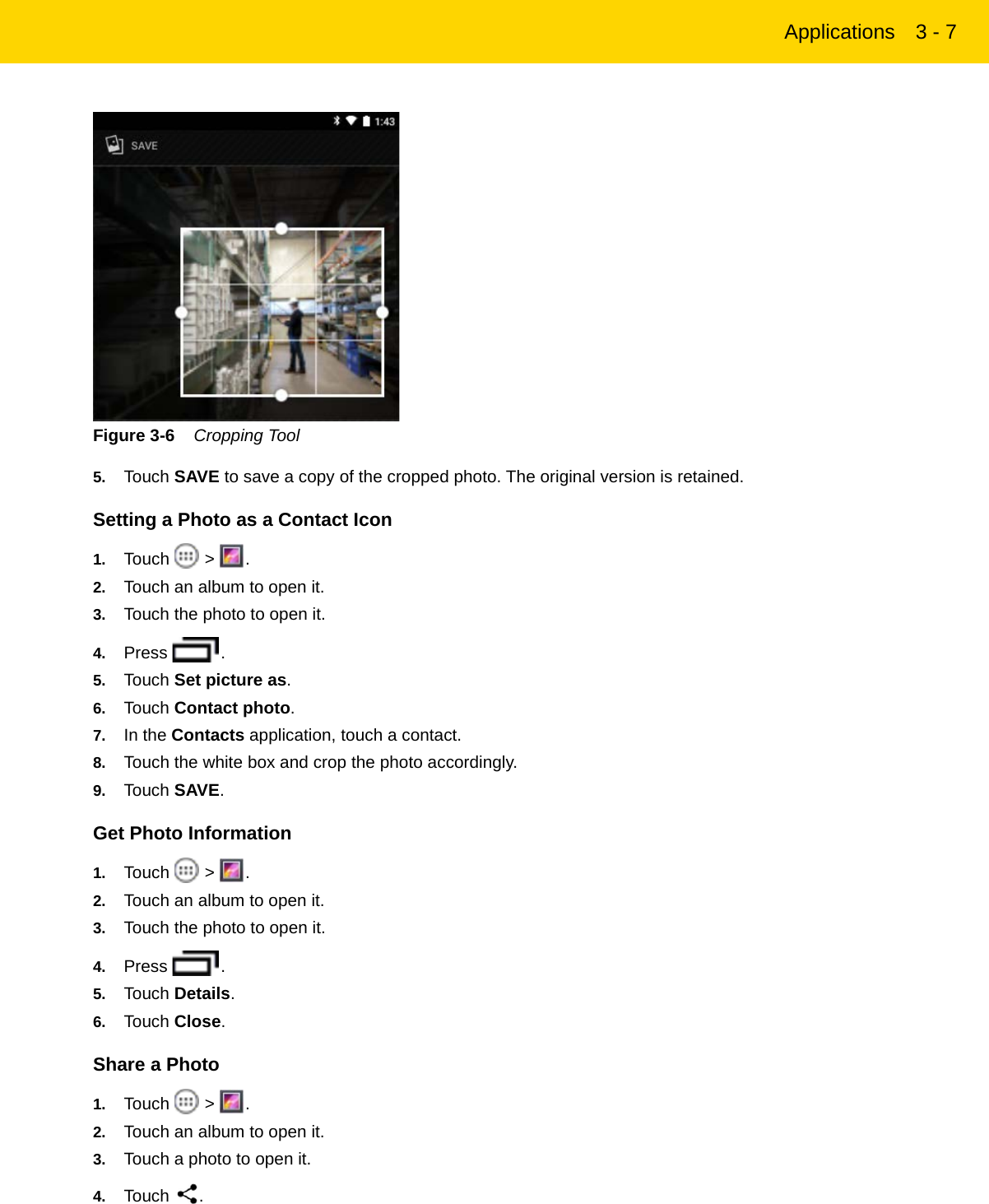
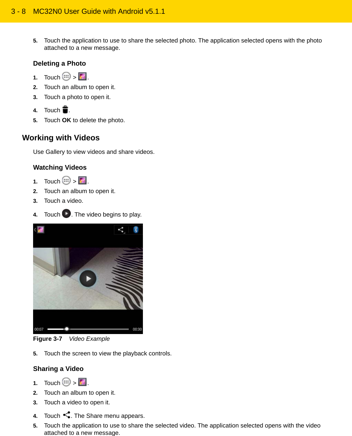
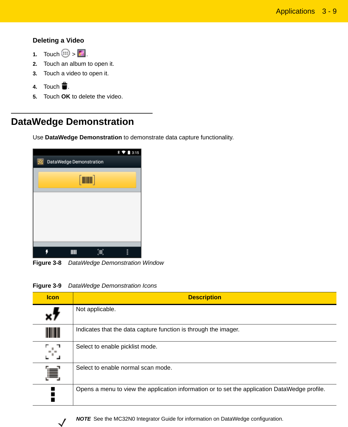
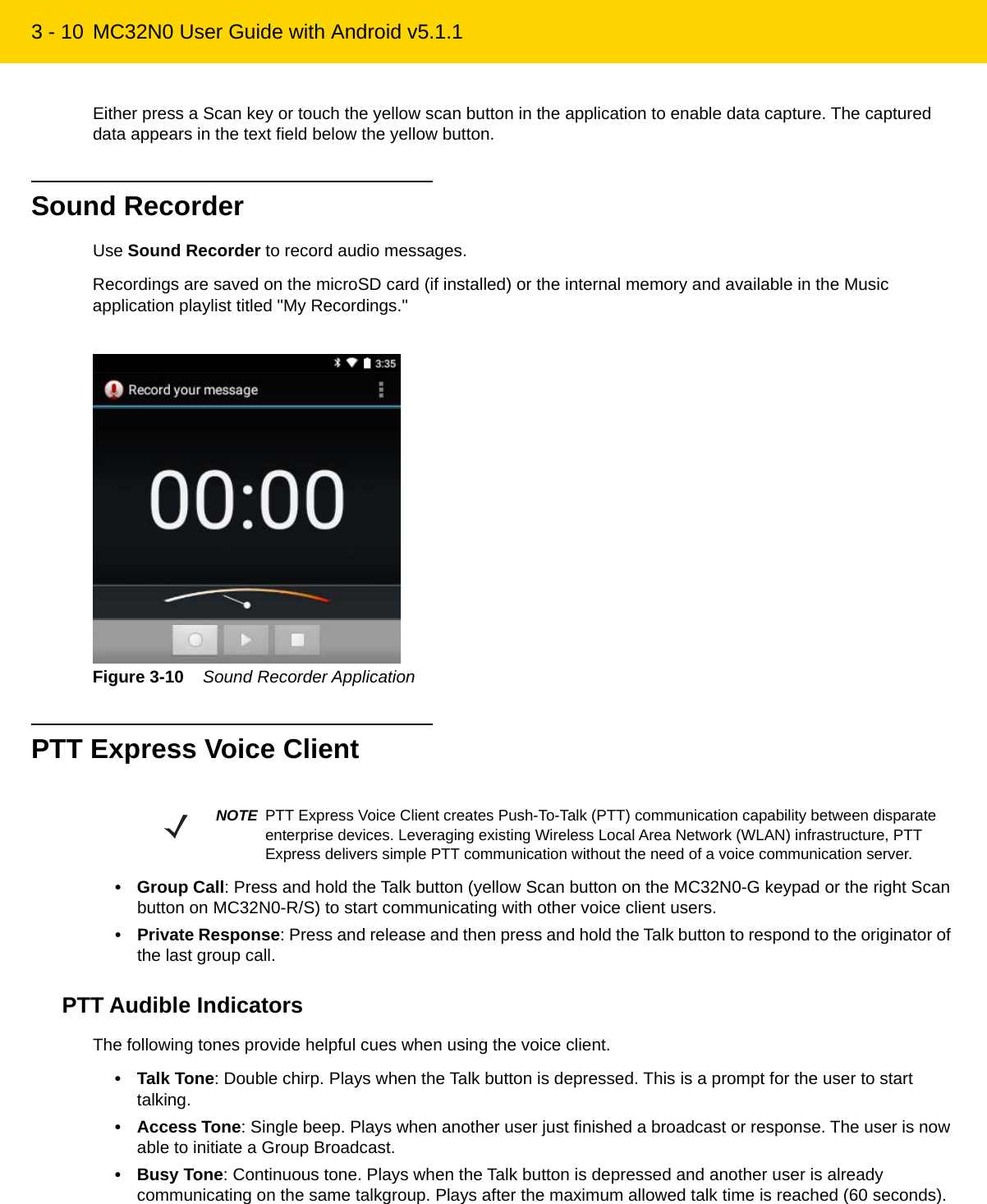
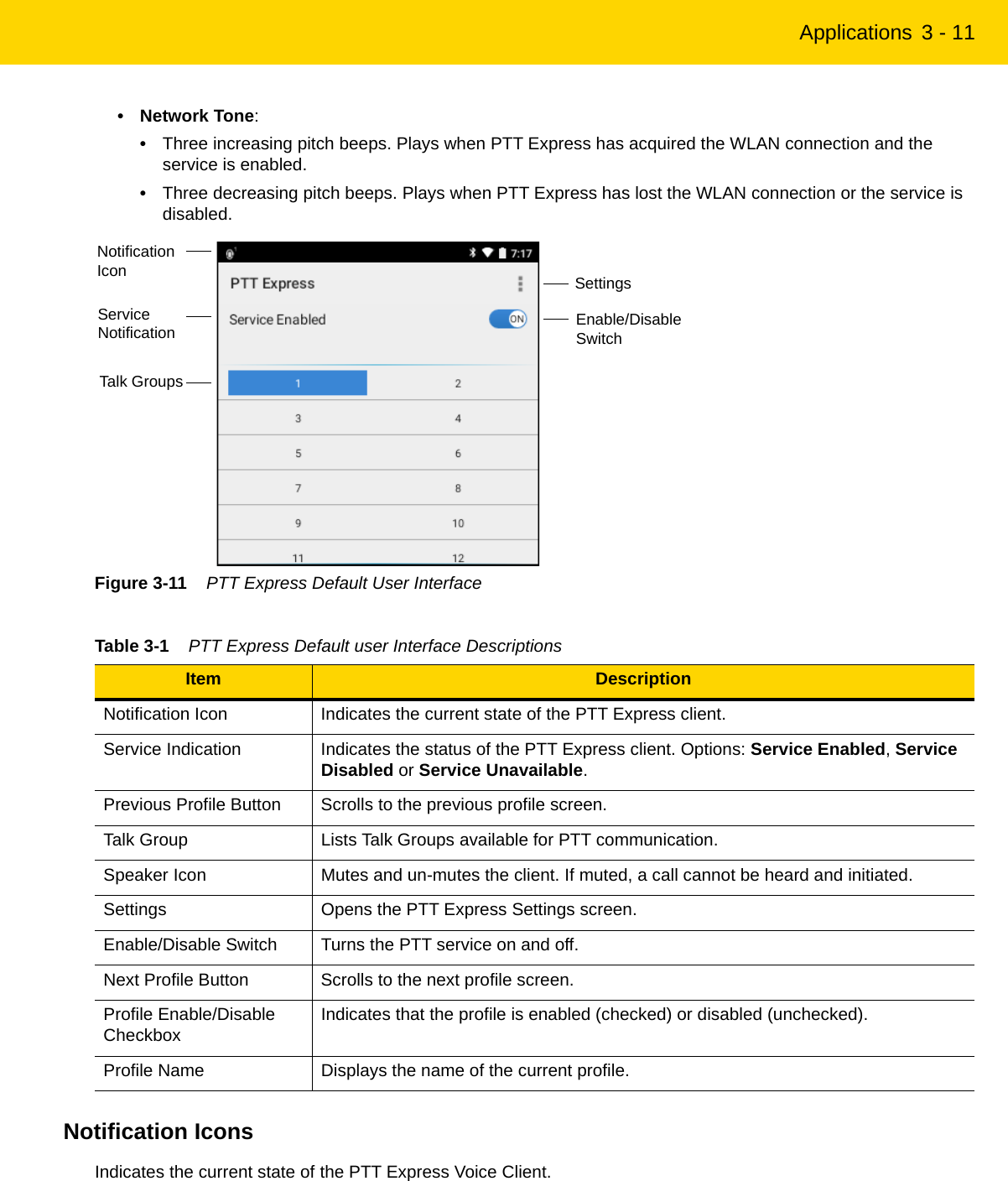
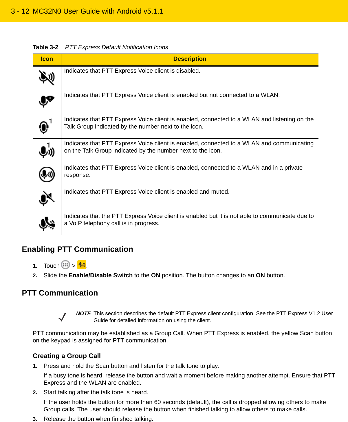
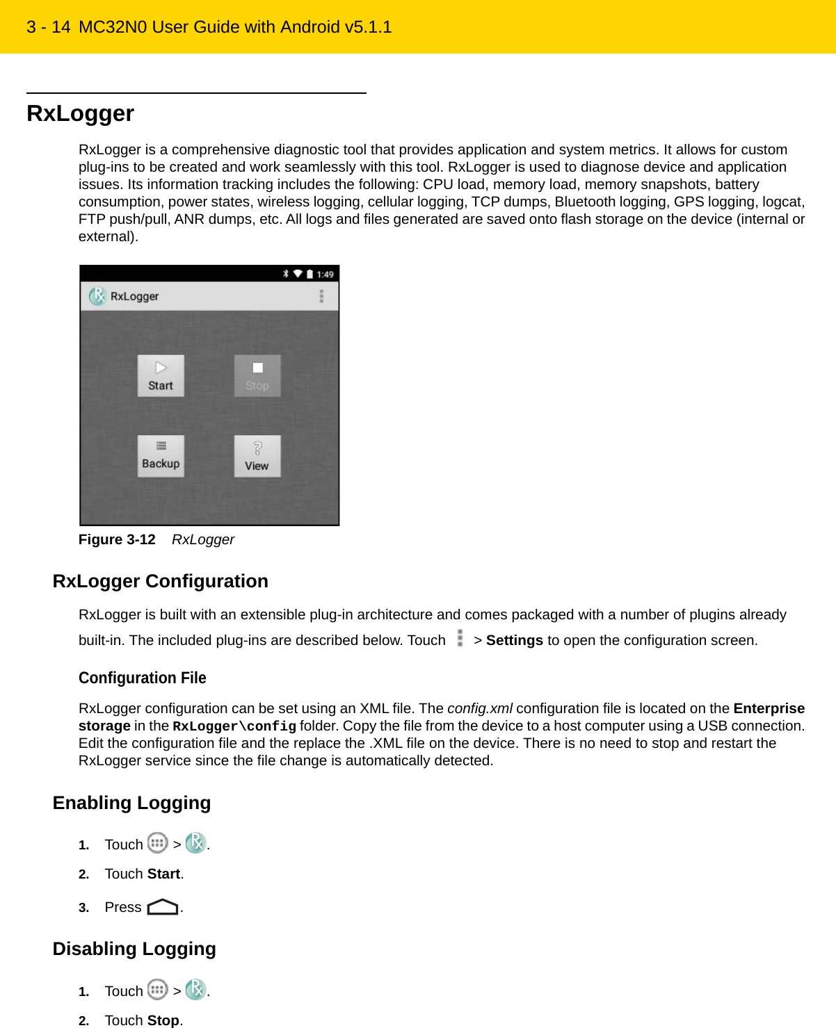
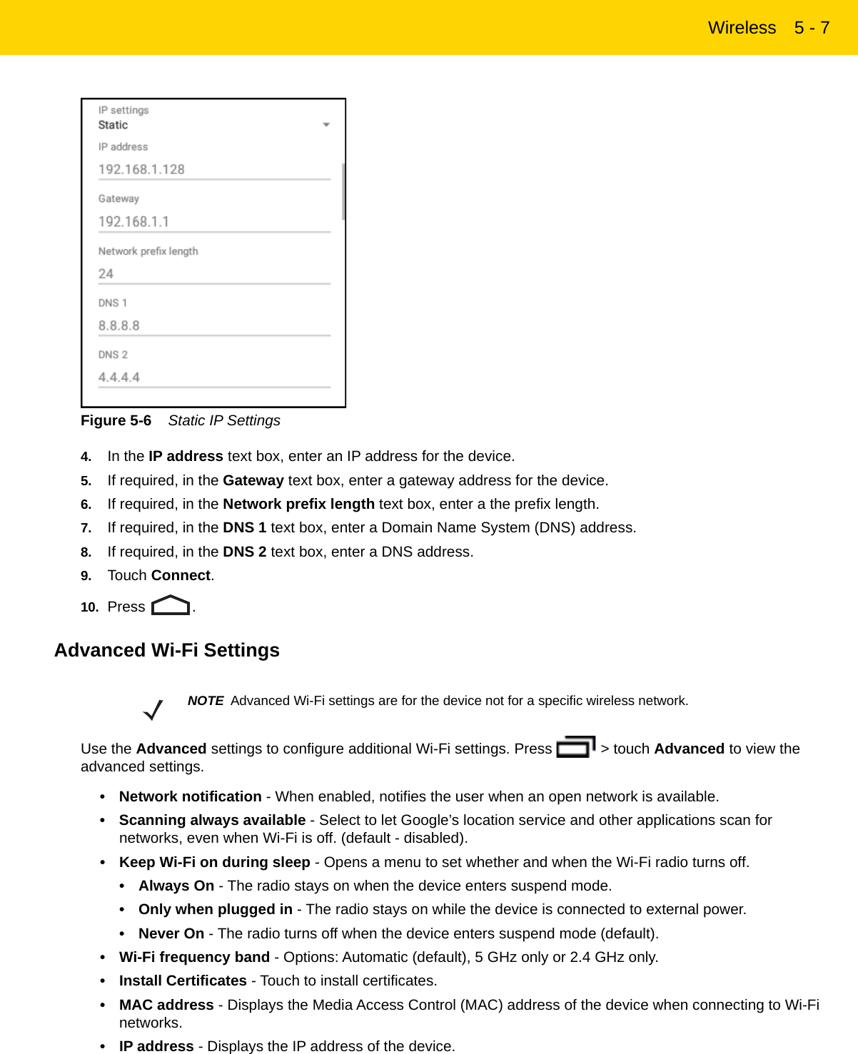
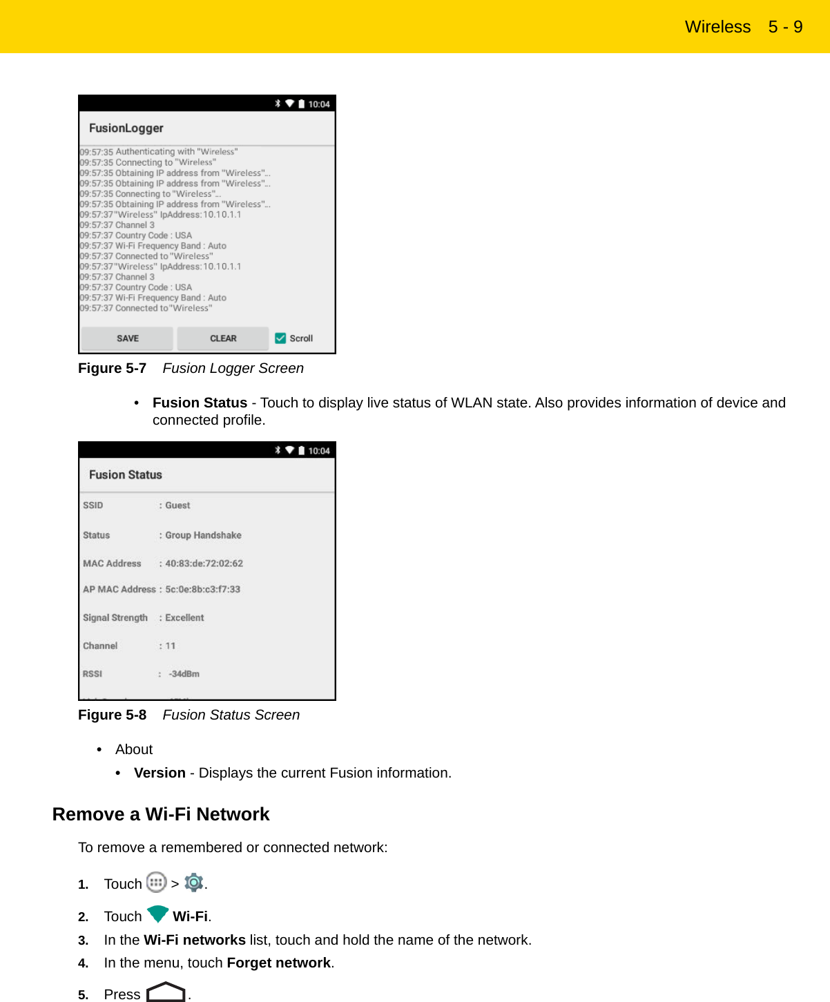
User Manual rev 51-100.pdf

Using the MC32 2 - 75. Position the icon on the screen and then release.Moving Items on the Home Screen1. Touch and hold the item until it floats on the screen.2. Drag the item to a new location. Pause at the edge of the screen to drag the item onto an adjacent Home screen.3. Lift finger to place the item on the Home screen.Removing an App or Widget from the Home Screen1. Go to the desired Home screen.2. Touch and hold the application shortcut or widget icon until it floats on the screen.3. Drag the icon to   on the top of the screen and then release.FoldersUse Folders to organize similar applications together. Tap the folder to open and display items in the folder.Creating FoldersTo create a folder, there must be at least two app icons on the Home screen.1. Go to the desired Home screen.2. Touch and hold on one application icon.3. Drag the icon and stack on top of another icon.4. Release the icon. A folder is created containing both icons.Naming Folders1. Touch the folder.Figure 2-4    Open Folder2. Touch the title area and enter a folder name using the keyboard.3. Touch anywhere on the Home screen or press   to close the folder. The folder name appears under the folder.REVIEW ONLY - REVIEW ONLY - REVIEW ONLY                             REVIEW ONLY - REVIEW ONLY - REVIEW ONLY
2 - 8 MC32N0 User Guide with Android v5.1.1Figure 2-5    Renamed FolderRemoving a Folder1. Touch and hold the folder icon until it enlarges and the device vibrates.2. Drag the icon to   and release.Home Screen WallpaperChange the Home Screen Wallpaper1. Touch and hold on the Home screen until the Choose Wallpaper from menu appears.2. Touch Gallery, Live wallpapers or Wallpapers.•Gallery - Select to use an image stored on the device.• Live wallpapers - Select to use an animated wallpaper image.• Wallpapers - Select to use a wallpaper image.3. Touch Save or Set wallpaper.Using the TouchscreenUse the screen to operate the device.• Touch - Touch to:•select items on the screen•type letters and symbols using the on-screen keyboard•press on-screen buttons.• Touch and Hold - Touch and hold:•an item on the Home screen to move it to a new location or to the trash.•an item in the All Apps screen to create a shortcut on the Home screen.•the Home screen to change the Home screen wallpaper.•Drag - Touch and hold an item for a moment and then move finger on the screen until reaching the new position.NOTE Use of Live Wallpaper may reduce battery life.REVIEW ONLY - REVIEW ONLY - REVIEW ONLY                             REVIEW ONLY - REVIEW ONLY - REVIEW ONLY
Using the MC32 2 - 9•Swipe- Move finger up and down or left and right on the screen to:•unlock the screen•view additional Home screens•view additional application icons in the All Apps screen•view more information on an application’s screen.• Double-tap - Tap twice on a web page, map, or other screen to zoom in and out.Using the On-screen KeyboardUse the on-screen keyboard to enter text in a text field. To configure the keyboard settings, touch and hold , (comma) or / (forward slash) >   and then select Android keyboard settings.Editing TextEdit entered text and use menu commands to cut, copy, and paste text within or across applications. Some applications do not support editing some or all of the text they display; others may offer their own way to select text.Entering Numbers, Symbols and Special CharactersTo enter numbers and symbols:•Touch and hold one of the top-row keys until a menu appears then select a number. Keys with alternate characters display an ellipsis ( ... ) below the character.•Touch and hold the Shift key with one finger, touch one or more capital letters or symbols to enter them, and then lift both fingers to return to the lowercase keyboard.•Touch ?123 to switch to the numbers and symbols keyboard.•Touch the =\< key on the numbers and symbols keyboard to view additional symbols.To enter special characters, touch and hold a number or symbol key to open a menu of additional symbols.•A larger version of the key displays briefly over the keyboard.•Keys with alternate characters display an ellipsis ( ... ) below the character.ApplicationsThe APPS screen displays icons for all installed applications. The table below lists the applications installed on the MC32N0. Refer to the MC32N0 Integrator Guide for information on installing and uninstalling applications.REVIEW ONLY - REVIEW ONLY - REVIEW ONLY                             REVIEW ONLY - REVIEW ONLY - REVIEW ONLY
2 - 10 MC32N0 User Guide with Android v5.1.1Table 2-5    Applications Icon DescriptionAppGallery - Provides links to utilities and demonstration applications that can be installed on the MC32N0.Battery Manager – Displays battery information, including charge level, status, health and wear level.Bluetooth Pairing – Use to pair the RS507 Hands-free imager with the MC32N0 by scanning a bar code.Browser - Use to access the Internet or intranet.Calculator - Provides the basic and scientific arithmetic functions.Calendar - Use to manage events and appointments.Clock - Use to schedule alarms for appointments or as a wake-up.Contacts - Use to manage contact information.DataWedge - Enables data capture using the camera or optional scanner.Downloads - lists all downloads files.DWDemo - Provides a way to demonstrate the data capture features using the Linear Imager. See DataWedge Demonstration for more information.elemez — Use to provide diagnostic information. See Elemez on page 3-15 for more information.Email - Use to send and receive email.File Browser - Organize and manage files on the MC32N0. See File Browser for more information.REVIEW ONLY - REVIEW ONLY - REVIEW ONLY                             REVIEW ONLY - REVIEW ONLY - REVIEW ONLY
Using the MC32 2 - 11Gallery - Use to view photos stored on the microSD card and internal memory. For more information, see Gallery for more information.Mobi Control Stage – Opens the Mobi Control Stage application to stage the MC32N0.MSP Agent - Enables management of the MC32N0 from an MSP server. Requires the purchase of an appropriate MSP client license per device to suit the level of management functionality required.Music - Play music stored on the microSD card and internal memory.PTT Express – Use to launch the PTT Express client for Voice over IP (VoIP) communication.Rapid Deployment- Allows the MC32N0 to stage a device for initial use by initiating the deployment of settings, firmware and software. Requires the purchase of an MSP client license per device.RxLogger – Use to diagnose device and application issues. See RxLogger on page 3-14 for more information.Search - Use the Google™ search engine to search the Internet and the MC32N0.Settings - Use to configure the MC32N0.Sound Recorder - Use to record audio.StageNow - Allows the MC32N0 to stage a device for initial use by initiating the deployment of settings, firmware and software.Terminal Emulation – Opens Wavelink Terminal Emulation application.Velocity - Opens the Wavelink terminal emulation application.AppLock Administrator - Use to configure the Application Lock feature. This icon appears after the optional MX feature is installed.MultiUser Administrator - Use to configure the MultiUser feature. This icon appears after the optional MX feature is installed.Table 2-5    Applications  (Continued)Icon DescriptionREVIEW ONLY - REVIEW ONLY - REVIEW ONLY                             REVIEW ONLY - REVIEW ONLY - REVIEW ONLY
2 - 12 MC32N0 User Guide with Android v5.1.1Accessing ApplicationsAll applications installed on the device are accessed using the APPS window.1. On the Home screen touch  . The APPS window displays.Figure 2-6    APPS Window2. Slide the APPS window left or right to view more application icons. Touch an icon to open the application.See Application Shortcuts and Widgets on page 2-6 for information on creating a shortcut on the Home screen.Switching Between Recent Applications1. Press and hold  . A window appears on the screen with icons of recently used applications.Figure 2-7    Recently Used Applications2. Slide the window up and down to view all recently used applications.3. Swipe left or right to remove application from the list and force close the application.4. Touch an icon to open it or press   to return to the current screen.REVIEW ONLY - REVIEW ONLY - REVIEW ONLY                             REVIEW ONLY - REVIEW ONLY - REVIEW ONLY
Using the MC32 2 - 13Un-Locking the ScreenUse the Lock screen to protect access to data on the MC32N0. Some email accounts require locking the screen. Refer to the MC32N0 Integrator Guide for information on setting up the locking feature. The Locking feature functions differently in Single User mode or Multiple User mode.Single User ModeWhen locked, a pattern, PIN or password is required to unlock the device. Press the Power button to lock the screen. The device also locks after a pre-defined time-out.Press and release the Power button to wake the device.The Lock screen displays. Slide   up to unlock the screen.If the Pattern screen unlock feature is enabled, the Pattern screen appears instead of the Lock screen.If the PIN or Password screen unlock feature is enabled, enter the PIN or password after unlocking the screen.Figure 2-8    Lock ScreenFigure 2-9    PIN ScreenREVIEW ONLY - REVIEW ONLY - REVIEW ONLY                             REVIEW ONLY - REVIEW ONLY - REVIEW ONLY
2 - 14 MC32N0 User Guide with Android v5.1.1Figure 2-10    Pattern ScreenFigure 2-11    Password ScreenMultiUser ModeWith MultiUser login, multiple users can log on to the device with each user having access to various applications and features. When enabled, the Login screen appears after powering on, resetting or after the device wakes from suspend mode.MultiUser Login1. In the Login text field, enter the username.REVIEW ONLY - REVIEW ONLY - REVIEW ONLY                             REVIEW ONLY - REVIEW ONLY - REVIEW ONLY
Using the MC32 2 - 15Figure 2-12    Multiple User Log In Screen2. In the Password text field, enter the password.3. Touch OK. After a resume from suspend, the user must enter the password.MultiUser Logout1. Drag the Status Bar down from the top of the screen.2. Touch MultiUser is active.3. Touch Logout.4. The Login screen appears.Resetting the DeviceThere are two reset functions, soft reset and hard reset.Performing a Soft ResetPerform a soft reset if applications stop responding.1. Press and hold the Power button until the menu appears.2. Touch Reset.3. The device reboots.Performing a Hard ResetPerform a Hard Reset if the device stops responding. To perform a Hard Reset:1. Simultaneously press the Power button, 1 and 9 keys.2. The device reboots.NOTE All un-saved data is lost after performing a Hard Reset.REVIEW ONLY - REVIEW ONLY - REVIEW ONLY                             REVIEW ONLY - REVIEW ONLY - REVIEW ONLY
2 - 16 MC32N0 User Guide with Android v5.1.1Suspend ModeThe MC32N0 goes into suspend mode when the user presses the Power button or after a period of inactivity (set in the Display settings window).To wake the MC32N0 from Suspend mode, press the Power button.The Lock screen displays. Slide   up to unlock the screen. See Un-Locking the Screen on page 2-13.Figure 2-13    Lock ScreenNOTE If the user enters the PIN, password or pattern incorrectly five times, they must wait 30 seconds before trying again.If the user forgets the PIN, password or pattern contact the system administrator.REVIEW ONLY - REVIEW ONLY - REVIEW ONLY                             REVIEW ONLY - REVIEW ONLY - REVIEW ONLY
CHAPTER 3 APPLICATIONSIntroductionThis section describes the applications installed on the device.Battery ManagerThe Battery Manager provides detailed information about the battery.To open Battery Manager, touch   >  .Figure 3-1    Battery Manager ScreenBattery level - Indicate the current battery charge level.Time since charging- Indicates the amount of time since the device began charging. Displays when the MC32N0 is on AC power.REVIEW ONLY - REVIEW ONLY - REVIEW ONLY                             REVIEW ONLY - REVIEW ONLY - REVIEW ONLY
3 - 2 MC32N0 User Guide with Android v5.1.1Battery status• Not charging - Indicates that the MC32N0 is not connected to AC power.• Charging over AC - Indicates that the MC32N0 is connected to AC power and charging.Battery health - Indicates the health of the battery.Wear level - Indicates the health of the battery in graphical form.Advanced info - Tap to view additional battery information.File BrowserUse the File Browser application to view and mange files on the device.To open File Browser, touch   >  .Figure 3-2    File Browser ScreenThe address bar (1) indicates the current folder path. Touch the current folder path to manually enter a path and folder name.Use   (2) to select multiple files/folder.Use   (3) to view the internal storage root folder.Use   (4) to view the microSD card root folder.Use   (5) to view the previous folder or to exit the application.Touch and hold an item to perform an operation on that item. Select one of the options from the File Operations menu:• Information - View detailed information about the file or folder.•Move - Move the file or folder to a new location.• Copy - Copy the select file.• Delete - Delete the selected file.• Rename - Rename the select file.• Open as - Open the selected file as a specific file type.21345REVIEW ONLY - REVIEW ONLY - REVIEW ONLY                             REVIEW ONLY - REVIEW ONLY - REVIEW ONLY
Applications 3 - 3•Share - Share the file with other devices.ContactsUse the Contacts application to manage contacts.From a Home or Apps screen, touch  . Contacts opens to the main list of contacts. View contacts in three ways at the top of the screen: Groups, All contacts, and Favorites. Touch the tabs to change how to view the contacts. Swipe up or down to scroll through the lists.Adding Contacts1. In the Contacts application, touch  .2. If there are more than one account with contacts, touch the one to use.3. Type the contact’s name and other information. Touch a field to start typing, and swipe down to view all categories.4. To add more than one entry for a category – for example, to add a work address after typing a personal address - an additional category appears each time information is added. To open a menu with preset labels, such as Home or Work for an email address, touch the label to the right of the contact information.5. Press .Editing Contacts1. In the Contacts application, touch a contact to edit tab.2. Touch .3. Edit the contact information.4. Press .Deleting Contacts1. In the Contacts application, touch a contact to edit tab.2. Press .3. Touch Delete.4. Touch OK to confirm.GalleryUse Gallery to:•view photosNOTE The device supports the following image formats: jpeg, gif, png and bmp.The device supports the following video formats: H.263, H.264 and MPEG4 Simple Profile.REVIEW ONLY - REVIEW ONLY - REVIEW ONLY                             REVIEW ONLY - REVIEW ONLY - REVIEW ONLY
3 - 4 MC32N0 User Guide with Android v5.1.1•play videos•perform basic editing of photos•set photos as wallpaper•set photos as a contact photo•share photos and videos.To open the Gallery application, touch   >   or in the camera application touch the thumbnail image at the top right.Gallery presents all photos and videos stored on the microSD card and internal memory.Figure 3-3    Gallery — Albums•Touch an album to open it and view its contents. The photos and videos in the album are displayed in chronological order.•Touch a photo or video in an album to view it.•Press   to return to the main Gallery screen.Working with AlbumsAlbums are groups of images and videos in folders. Touch an album to open it. The photos and videos are listed in a chronologically ordered grid. The name of the album displays at the top of the screen.REVIEW ONLY - REVIEW ONLY - REVIEW ONLY                             REVIEW ONLY - REVIEW ONLY - REVIEW ONLY
Applications 3 - 5Figure 3-4    Photos Inside an AlbumSwipe left or right to scroll images across the screen.Share an Album1. Touch  > .2. Touch and hold an album until it highlights.3. Touch other albums as required.4. Touch  . The Share menu opens. Touch the application to use to share the selected albums.5. Follow the instructions within the selected application.Get Album Information1. Touch  > .2. Touch and hold an album until it highlights.3. Touch  > Details.Deleting an AlbumTo delete an album and its contents:1. Touch  > .2. Touch and hold an album until it highlights.3. Check other albums to delete. Ensure that other albums are selected.4. Touch .5. In the Delete selected item? menu, touch OK to delete the album.Working with PhotosUse Gallery to view, edit and share photos.REVIEW ONLY - REVIEW ONLY - REVIEW ONLY                             REVIEW ONLY - REVIEW ONLY - REVIEW ONLY
3 - 6 MC32N0 User Guide with Android v5.1.1Viewing and Browsing PhotosTo view a photo:1. Touch  > .2. Touch an album to open it.3. Touch a photo.Figure 3-5    Photo Example4. Swipe left or right to view the next or previous photo in the album.5. Touch the photo to view the controls.6. Double-tap the screen to zoom in or pinch two fingers together or spread them apart to zoom in or out.7. Drag the photo to view parts that are not in view.Cropping a Photo1. In Gallery, touch a photo to view the controls.2. Press .3. Touch Crop. The blue cropping tool appears.4. Use the cropping tool to select the portion of the photo to crop.•Drag from the inside of the cropping tool to move it.•Drag an edge of the cropping tool to resize it to any proportion.•Drag a corner of the cropping tool to resize it with fixed proportions.REVIEW ONLY - REVIEW ONLY - REVIEW ONLY                             REVIEW ONLY - REVIEW ONLY - REVIEW ONLY
Applications 3 - 7Figure 3-6    Cropping Tool5. Touch SAVE to save a copy of the cropped photo. The original version is retained.Setting a Photo as a Contact Icon1. Touch  > .2. Touch an album to open it.3. Touch the photo to open it.4. Press .5. Touch Set picture as.6. Touch Contact photo.7. In the Contacts application, touch a contact.8. Touch the white box and crop the photo accordingly.9. Touch SAVE.Get Photo Information1. Touch  > .2. Touch an album to open it.3. Touch the photo to open it.4. Press .5. Touch Details.6. Touch Close.Share a Photo1. Touch  > .2. Touch an album to open it.3. Touch a photo to open it.4. Touch .REVIEW ONLY - REVIEW ONLY - REVIEW ONLY                             REVIEW ONLY - REVIEW ONLY - REVIEW ONLY
3 - 8 MC32N0 User Guide with Android v5.1.15. Touch the application to use to share the selected photo. The application selected opens with the photo attached to a new message.Deleting a Photo1. Touch  > .2. Touch an album to open it.3. Touch a photo to open it.4. Touch .5. Touch OK to delete the photo.Working with VideosUse Gallery to view videos and share videos.Watching Videos1. Touch  > .2. Touch an album to open it.3. Touch a video.4. Touch  . The video begins to play.Figure 3-7    Video Example5. Touch the screen to view the playback controls.Sharing a Video1. Touch  > .2. Touch an album to open it.3. Touch a video to open it.4. Touch  . The Share menu appears.5. Touch the application to use to share the selected video. The application selected opens with the video attached to a new message.REVIEW ONLY - REVIEW ONLY - REVIEW ONLY                             REVIEW ONLY - REVIEW ONLY - REVIEW ONLY
Applications 3 - 9Deleting a Video1. Touch  > .2. Touch an album to open it.3. Touch a video to open it.4. Touch .5. Touch OK to delete the video.DataWedge DemonstrationUse DataWedge Demonstration to demonstrate data capture functionality.Figure 3-8    DataWedge Demonstration WindowFigure 3-9    DataWedge Demonstration Icons Icon DescriptionNot applicable.Indicates that the data capture function is through the imager.Select to enable picklist mode.Select to enable normal scan mode.Opens a menu to view the application information or to set the application DataWedge profile.NOTE See the MC32N0 Integrator Guide for information on DataWedge configuration.REVIEW ONLY - REVIEW ONLY - REVIEW ONLY                             REVIEW ONLY - REVIEW ONLY - REVIEW ONLY
3 - 10 MC32N0 User Guide with Android v5.1.1Either press a Scan key or touch the yellow scan button in the application to enable data capture. The captured data appears in the text field below the yellow button.Sound RecorderUse Sound Recorder to record audio messages.Recordings are saved on the microSD card (if installed) or the internal memory and available in the Music application playlist titled "My Recordings."Figure 3-10    Sound Recorder ApplicationPTT Express Voice Client• Group Call: Press and hold the Talk button (yellow Scan button on the MC32N0-G keypad or the right Scan button on MC32N0-R/S) to start communicating with other voice client users.• Private Response: Press and release and then press and hold the Talk button to respond to the originator of the last group call.PTT Audible IndicatorsThe following tones provide helpful cues when using the voice client.• Talk Tone: Double chirp. Plays when the Talk button is depressed. This is a prompt for the user to start talking.• Access Tone: Single beep. Plays when another user just finished a broadcast or response. The user is now able to initiate a Group Broadcast.•Busy Tone: Continuous tone. Plays when the Talk button is depressed and another user is already communicating on the same talkgroup. Plays after the maximum allowed talk time is reached (60 seconds).NOTE PTT Express Voice Client creates Push-To-Talk (PTT) communication capability between disparate enterprise devices. Leveraging existing Wireless Local Area Network (WLAN) infrastructure, PTT Express delivers simple PTT communication without the need of a voice communication server.REVIEW ONLY - REVIEW ONLY - REVIEW ONLY                             REVIEW ONLY - REVIEW ONLY - REVIEW ONLY
Applications 3 - 11•Network Tone: •Three increasing pitch beeps. Plays when PTT Express has acquired the WLAN connection and the service is enabled.•Three decreasing pitch beeps. Plays when PTT Express has lost the WLAN connection or the service is disabled.Figure 3-11    PTT Express Default User InterfaceNotification IconsIndicates the current state of the PTT Express Voice Client.Table 3-1    PTT Express Default user Interface Descriptions Item DescriptionNotification Icon Indicates the current state of the PTT Express client.Service Indication Indicates the status of the PTT Express client. Options: Service Enabled, Service Disabled or Service Unavailable.Previous Profile Button Scrolls to the previous profile screen.Talk Group Lists Talk Groups available for PTT communication.Speaker Icon Mutes and un-mutes the client. If muted, a call cannot be heard and initiated.Settings Opens the PTT Express Settings screen.Enable/Disable Switch Turns the PTT service on and off.Next Profile Button Scrolls to the next profile screen.Profile Enable/Disable Checkbox Indicates that the profile is enabled (checked) or disabled (unchecked).Profile Name Displays the name of the current profile.NotificationIconService NotificationTalk GroupsSettingsEnable/DisableSwitchREVIEW ONLY - REVIEW ONLY - REVIEW ONLY                             REVIEW ONLY - REVIEW ONLY - REVIEW ONLY
3 - 12 MC32N0 User Guide with Android v5.1.1Enabling PTT Communication1. Touch  > .2. Slide the Enable/Disable Switch to the ON position. The button changes to an ON button.PTT CommunicationPTT communication may be established as a Group Call. When PTT Express is enabled, the yellow Scan button on the keypad is assigned for PTT communication.Creating a Group Call1. Press and hold the Scan button and listen for the talk tone to play.If a busy tone is heard, release the button and wait a moment before making another attempt. Ensure that PTT Express and the WLAN are enabled.2. Start talking after the talk tone is heard.If the user holds the button for more than 60 seconds (default), the call is dropped allowing others to make Group calls. The user should release the button when finished talking to allow others to make calls.3. Release the button when finished talking.Table 3-2    PTT Express Default Notification IconsIcon DescriptionIndicates that PTT Express Voice client is disabled.Indicates that PTT Express Voice client is enabled but not connected to a WLAN.Indicates that PTT Express Voice client is enabled, connected to a WLAN and listening on the Talk Group indicated by the number next to the icon.Indicates that PTT Express Voice client is enabled, connected to a WLAN and communicating on the Talk Group indicated by the number next to the icon.Indicates that PTT Express Voice client is enabled, connected to a WLAN and in a private response.Indicates that PTT Express Voice client is enabled and muted.Indicates that the PTT Express Voice client is enabled but it is not able to communicate due to a VoIP telephony call is in progress.NOTE This section describes the default PTT Express client configuration. See the PTT Express V1.2 User Guide for detailed information on using the client.REVIEW ONLY - REVIEW ONLY - REVIEW ONLY                             REVIEW ONLY - REVIEW ONLY - REVIEW ONLY
Applications 3 - 13Responding with a Private ResponseThe Private Response can only be initiated once a Group Call has been established. The initial Private Response is made to the originator of the Group Call.1. Wait until an access tone is heard.2. Press and release and then press and hold the Talk button and listen for the talk tone to play.If a busy tone is heard, release the button and wait a moment before making another attempt. Ensure that PTT Express and the WLAN are enabled.3. Start talking after the talk tone plays.4. Release the button when finished talking.Disabling PTT Express Voice Client Communication1. Touch  > .2. Slide the Enable/Disable Switch to the OFF position. The button changes to OFF.3. Press .REVIEW ONLY - REVIEW ONLY - REVIEW ONLY                             REVIEW ONLY - REVIEW ONLY - REVIEW ONLY
3 - 14 MC32N0 User Guide with Android v5.1.1RxLoggerRxLogger is a comprehensive diagnostic tool that provides application and system metrics. It allows for custom plug-ins to be created and work seamlessly with this tool. RxLogger is used to diagnose device and application issues. Its information tracking includes the following: CPU load, memory load, memory snapshots, battery consumption, power states, wireless logging, cellular logging, TCP dumps, Bluetooth logging, GPS logging, logcat, FTP push/pull, ANR dumps, etc. All logs and files generated are saved onto flash storage on the device (internal or external).Figure 3-12    RxLoggerRxLogger ConfigurationRxLogger is built with an extensible plug-in architecture and comes packaged with a number of plugins already built-in. The included plug-ins are described below. Touch   > Settings to open the configuration screen.Configuration FileRxLogger configuration can be set using an XML file. The config.xml configuration file is located on the Enterprise storage in the RxLogger\config folder. Copy the file from the device to a host computer using a USB connection. Edit the configuration file and the replace the .XML file on the device. There is no need to stop and restart the RxLogger service since the file change is automatically detected.Enabling Logging1. Touch  > .2. Touch Start.3. Press .Disabling Logging1. Touch  > .2. Touch Stop.REVIEW ONLY - REVIEW ONLY - REVIEW ONLY                             REVIEW ONLY - REVIEW ONLY - REVIEW ONLY
Applications 3 - 153. Press .Extracting Log Files1. Connect the device to a host computer using an USB connection.2. Using a file explorer, navigate to the Internal Storage in the /RxLogger folder.3. Copy the file from the device to the host computer.4. Disconnect the device from the host computer.ElemezUse Elemez to provide diagnostics information to us. Touch Submit Diagnostics button to send the data.Figure 3-13    Elemez ApplicationDisabling Elemez Data CollectionThe user can disable the Elemez application from collection specific data in the background and sending it to Zebra Technologies.1. Press .2. Touch Manage Apps.3. Swipe left or right until the ALL tab displays.4. Scroll through the list and touch Elemez.5. In the App info screen, touch Uninstall updates.NOTE Elemez collects specific device information in the background and sends this information to us to help improve product functionality. This feature can be disabled. See Disabling Elemez Data Collection. Ensure that the date, time and time zone are set correctly prior to using Elemez.REVIEW ONLY - REVIEW ONLY - REVIEW ONLY                             REVIEW ONLY - REVIEW ONLY - REVIEW ONLY
3 - 16 MC32N0 User Guide with Android v5.1.16. In the Uninstall updates dialog box, touch OK.7. Touch OK.8. After uninstall is complete, touch OK.9. In the All tab, scroll through the list and touch Elemez.10. Touch Disable.11. In the Disable built-in app? dialog box, touch OK.12. Press .Enabling Elemez Data CollectionThe user can re-enable the Elemez application for collection specific data in the background and sending it to Zebra Technologies.1. Press .2. Touch Manage Apps.3. Swipe left or right until the ALL tab displays.4. Scroll through the list and touch Elemez.5. In the App info screen, touch Enable.6. Press .7. Touch  > .8. Touch Enable Elemez.REVIEW ONLY - REVIEW ONLY - REVIEW ONLY                             REVIEW ONLY - REVIEW ONLY - REVIEW ONLY
CHAPTER 4 DATA CAPTUREIntroductionThis chapter provides information for capturing bar code data using the internal camera and optional scan modules and Bluetooth scanner.The MC32N0 offers the following data capture options:•imager.•laser scanner.•RS507 Hands-free imager.ImagerThe device with an integrated imager has the following features:•Omnidirectional reading of a variety of bar code symbologies, including the most popular linear, postal, PDF417, and 2D matrix code types.•Advanced intuitive laser aiming cross-hair for easy point-and-shoot operation.The modules uses digital camera technology to take a digital picture of a bar code, stores the resulting image in its memory, and executes state-of-the-art software decoding algorithms to extract the data from the image.Operational ModesThe device with an integrated imager supports two modes of operation, listed below. Activate each mode by pressing a scan button.NOTE DataWedge is installed and enabled on the MC32N0 by default.By default, the good decode beep is set to system volume (Music and Media). The good decode beep can be set to another sound (Notifications or Alarms) and the volume can be independently controlled. See the DataWedge section in the MC32N0 Integrator Guide for more information.REVIEW ONLY - REVIEW ONLY - REVIEW ONLY                             REVIEW ONLY - REVIEW ONLY - REVIEW ONLY
4 - 2 MC32N0 User Guide with Android v5.1.1• Decode Mode: In this mode, the device attempts to locate and decode enabled bar codes within its field of view. The imager remains in this mode as long as the user holds the scan button, or until it decodes a bar code.• Pick List Mode: This mode allows the user to selectively decode a bar code when more than one bar code is in the device’s field of view. To accomplish this, move the aiming crosshair over the required bar code to decode only this bar code. This feature is ideal for pick lists containing multiple bar codes and manufacturing or transport labels containing more than one bar code type (either 1D or 2D).Laser ScannerThe MC32N0 with laser scanner has the following features:•Reading of a variety of bar code symbologies, including the most popular linear, postal, and 1-D code types.•Intuitive aiming for easy point-and-shoot operation.RS507 Hands-Free ImagerThe RS507 Hands-free Imager is a wearable bar code scan solution for both 1D and 2D bar code symbologies. The scanner supports Simple Serial Interface (SSI) andBluetooth Human Interface Device (HID) connection to the device where the scanner emulates a keyboard.Figure 4-1    RS507 Hands-Free ImagerSee to the RS507 Hands-free Imager Product Reference Guide for more information.Scanning ConsiderationsTypically, scanning is a simple matter of aim, scan, and decode where a few quick trial efforts master it. However, consider the following to optimize scanning performance:•Range•Any scanning device decodes well over a particular working range — minimum and maximum distances from the bar code. This range varies according to bar code density and scanning device optics.Scanning within range brings quick and constant decodes; scanning too close or too far away prevents decodes. Move the scanner closer and farther away to find the right working range for the bar codes being scanned.NOTE To enable Pick List Mode, configure in DataWedge.REVIEW ONLY - REVIEW ONLY - REVIEW ONLY                             REVIEW ONLY - REVIEW ONLY - REVIEW ONLY
Data Capture 4 - 3•Angle•Scan angle is important for promoting quick decodes. When laser beams reflect directly back into the scanner from the bar code, this specular reflection can “blind” the scanner.To avoid this, scan the bar code so that the beam does not bounce directly back. But do not scan at too sharp an angle; the scanner needs to collect scattered reflections from the scan to make a successful decode. Practice quickly shows what tolerances to work within.•Hold the device farther away for larger symbols.•Move the device closer for symbols with bars that are close together.Bar Code Capture with ImagerTo capture bar code data:1. Ensure that an application is open on the device and a text field is in focus (text cursor in text field).2. Point the top of the device at a bar code.Figure 4-2    Bar Code Scanning – MC32N0–GFigure 4-3    Bar Code Scanning – MC32N0–S3. Press and hold the Scan button or Trigger.The red laser aiming pattern turns on to assist in aiming. 4. Ensure the bar code is within the area formed by the cross-hairs in the aiming pattern. The aiming dot is used for increased visibility in bright lighting conditions.The Scan LEDs light green and a beep sounds, by default, to indicate the bar code was decoded successfully. Note that when the device is in Pick List Mode, the device does not decode the bar code until the center of the crosshair touches the bar code.NOTE Scanning procedures depend on the application and device configuration. An application may use different scanning procedures from those described.REVIEW ONLY - REVIEW ONLY - REVIEW ONLY                             REVIEW ONLY - REVIEW ONLY - REVIEW ONLY
4 - 4 MC32N0 User Guide with Android v5.1.1Figure 4-4    Aiming PatternFigure 4-5    Pick List Mode with Multiple Bar Codes in Aiming Pattern5. Release the scan button or Trigger.6. The bar code content data appears in the text field.Bar Code Capture with Laser ScannerTo capture bar code data:1. Ensure that an application is open on the device and a text field is in focus (text cursor in text field).2. On the MC32N0–R, rotate the Turret for optimal scanning position.3. Point the scan exit window at a bar code.Figure 4-6    Bar Code Scanning – MC32N0–R4. Press and hold the Scan button.The red scan line turns on to assist in aiming. Ensure that the scan line crosses every bar and space of the bar code.REVIEW ONLY - REVIEW ONLY - REVIEW ONLY                             REVIEW ONLY - REVIEW ONLY - REVIEW ONLY
Data Capture 4 - 5The Scan LEDs light green and a beep sounds, by default, to indicate the bar code was decoded successfully.Figure 4-7    Linear Scanner Aiming Pattern5. Release the scan button.6. The captured data appears in the text field.Bar Code Capture with RS507 Hands-Free ImagerPair the RS507 with the MC32N0. See Pairing the RS507 Hands-Fee Imager Using SSI on page 4-6 or Pairing the RS507 Hands-Free Imager Bluetooth HID on page 4-7.1. Ensure that an application is open on the device and a text field is in focus (text cursor in text field).2. Point the RS507 at a bar code.Figure 4-8    Bar Code Scanning with RS5073. Press and hold the trigger.The red laser aiming pattern turns on to assist in aiming. Ensure the bar code is within the area formed by the cross-hairs in the aiming pattern. The aiming dot is used for increased visibility in bright lighting conditions.The RS507 LEDs light green, a beep sounds to indicate the bar code was decoded successfully. Note that when the RS507 is in Pick List Mode, the RS507 does not decode the bar code until the center of the crosshair touches the bar code.REVIEW ONLY - REVIEW ONLY - REVIEW ONLY                             REVIEW ONLY - REVIEW ONLY - REVIEW ONLY
4 - 6 MC32N0 User Guide with Android v5.1.1Figure 4-9    Aiming PatternFigure 4-10    Pick List Mode with Multiple Bar Codes in Aiming Pattern4. The captured data appears in the text field.Pairing the RS507 Hands-Fee Imager Using SSIAn RS507 Hands-free Imager can be used with the device to capture bar code data.1. Ensure that the two devices are within 10 meters (32.8 feet) of one another.2. Install the battery into the RS507.3. On the MC32N0, touch   >  .Figure 4-11    Bluetooth Pairing UtilityREVIEW ONLY - REVIEW ONLY - REVIEW ONLY                             REVIEW ONLY - REVIEW ONLY - REVIEW ONLY
Data Capture 4 - 74. Using the RS507, scan the bar code on the screen.The RS507 emits a high/low/high/low beeps. The Scan LED flashes green indicating that the RS507 is attempting to establish connection with the MC32N0. When connection is established, the Scan LED turns off and the RS507 emits one string of low/high beeps.5. On the MC32N0, touch  .Pairing the RS507 Hands-Free Imager Bluetooth HIDAn RS507 Hands-free Imager can be used with the device to capture bar code data.1. Ensure that Bluetooth is enabled on both devices.2. Ensure that the Bluetooth device to discover is in discoverable mode.3. Ensure that the two devices are within 10 meters (32.8 feet) of one another.4. Place the RS507 in Human Interface Device (HID) mode. If the RS507 is already in HID mode, skip to step 5.a. Remove the battery from the RS507.b. Press and hold the Restore key.c. Install the battery onto the RS507.d. Keep holding the Restore key for about five seconds until a chirp is heard and the Scan LEDs flash green.e. Scan the bar code below to place the RS507 in HID mode.Figure 4-12    RS507 Bluetooth HID Bar Code5. Remove the battery from the RS507.6. Re-install the battery into the RS507.7. On the MC32N0, touch   >  .8. Touch  Bluetooth.9. Touch SCAN FOR DEVICES. The device begins searching for discoverable Bluetooth devices in the area and displays them under AVAILABLE DEVICES.10. Scroll through the list and select RS507.The device connects to the RS507 and Connected appears below the device name. The Bluetooth device is added to the Bluetooth devices list and a trusted (“paired”) connection is established.DataWedgeDataWedge is a utility that adds advanced bar code scanning capability to any application without writing code. It runs in the background and handles the interface to built-in bar code scanners. The captured bar code data is converted to keystrokes and sent to the target application as if it was typed on the keypad.To configure DataWedge refer to the MC32N0 Integrator Guide.REVIEW ONLY - REVIEW ONLY - REVIEW ONLY                             REVIEW ONLY - REVIEW ONLY - REVIEW ONLY
4 - 8 MC32N0 User Guide with Android v5.1.1Enabling DataWedge1. Touch  > .2. Press .3. Touch Settings.4. Touch the DataWedge enabled checkbox. A blue checkmark appears in the checkbox indicating that DataWedge is enabled.5. Press .Disabling DataWedge1. Touch  > .2. Press .3. Touch Settings.4. Touch the DataWedge enabled checkbox. The blue checkmark disappears from the checkbox indicating that DataWedge is disabled.5. Press .REVIEW ONLY - REVIEW ONLY - REVIEW ONLY                             REVIEW ONLY - REVIEW ONLY - REVIEW ONLY
CHAPTER 5 WIRELESSIntroductionThis section provides information on the wireless features:•Wireless Local Area Network (WLAN)•BluetoothWireless Local Area NetworksWireless local area networks (WLANs) allow the MC32N0 to communicate wirelessly inside a building. Before using the MC32N0 on a WLAN, the facility must be set up with the required hardware to run the WLAN (sometimes known as infrastructure). The infrastructure and the MC32N0 must both be properly configured to enable this communication.Refer to the documentation provided with the infrastructure (access points (APs), access ports, switches, Radius servers, etc.) for instructions on how to set up the infrastructure.Once the infrastructure is set up to enforce the chosen WLAN security scheme, use the Wireless & networks settings configure the MC32N0 to match the security scheme.The MC32N0 supports the following WLAN security options:•Open•Wireless Equivalent Privacy (WEP)•Wi-Fi Protected Access (WPA)/WPA2 Personal (PSK)•Extensible Authentication Protocol (EAP)•LEAP•FAST - with Microsoft Challenge-Handshake Authentication Protocol version 2 (MSCHAPv2) and Generic Token Card (GTC) authentication.•Protected Extensible Authentication Protocol (PEAP) - with MSCHAPV2 and GTC authentication.•Transport Layer Security (TLS)•TTLS - with Password Authentication Protocol (PAP), MSCHAP and MSCHAPv2 authentication.REVIEW ONLY - REVIEW ONLY - REVIEW ONLY                             REVIEW ONLY - REVIEW ONLY - REVIEW ONLY
5 - 2 MC32N0 User Guide with Android v5.1.1The Status bar displays icons that indicate Wi-Fi network availability and Wi-Fi status. See Status Bar on page 2-2 for more information.Scan and Connect to a Wi-Fi Network1. Touch  > .2. Touch  Wi-Fi.Figure 5-1    Settings Screen3. Slide the Wi-Fi switch to the ON position. The MC32N0 searches for WLANs in the area and lists them.Figure 5-2    Wi-Fi Screen4. Scroll through the list and select the desired WLAN network.NOTE Turn off Wi-Fi when not using it, to extend the life of the battery.REVIEW ONLY - REVIEW ONLY - REVIEW ONLY                             REVIEW ONLY - REVIEW ONLY - REVIEW ONLY
Wireless 5 - 35. For open networks, touch profile once or press and hold and then select Connect to network or for secure networks enter the required password or other credentials then touch Connect. See the system administrator for more information.The MC32N0 obtains a network address and other required information from the network using the dynamic host configuration protocol (DHCP) protocol. To configure the MC32N0 with a fixed internet protocol (IP) address, See Configuring the Device to Use a Static IP Address on page 5-6.6. In the Wi-Fi setting field, Connected appears indicating that the MC32N0 is connected to the WLAN.Configuring a Wi-Fi NetworkTo set up a Wi-Fi network:1. Touch  > .2. Touch  Wi-Fi.3. Slide the switch to the ON position. The device searches for WLANs in the area and lists them on the screen.4. Scroll through the list and select the desired WLAN network.5. Touch the desired network. If the network security is Open, the device automatically connects to the network. For all other network security a dialog box appears.Figure 5-3    WLAN Network Security Dialog Box6. If the network security is WEP or WPA/WPS2 PSK, enter the required password and then touch Connect.REVIEW ONLY - REVIEW ONLY - REVIEW ONLY                             REVIEW ONLY - REVIEW ONLY - REVIEW ONLY
5 - 4 MC32N0 User Guide with Android v5.1.1Figure 5-4    802.1x EAP Security Dialog Box7. If the network security is 802.1x EAP:•Touch the EAP method drop-down list and select PEAP, TLS, TTLS or PWD.•Touch the Phase 2 authentication drop-down list and select an authentication method.•If required, touch CA certificate and select a Certification Authority (CA) certificate. Note: Certificates are installed using the Security settings.•If required, touch User certificate and select a user certificate. Note: User certificates are installed using the Security settings.•If required, in the Identity text box, enter the username credentials.•If desired, in the Anonymous identity text box, enter an anonymous identity username.•If required, in the Password text box, enter the password for then given identity.8. Touch Connect.9. Press .Manually Adding a Wi-Fi NetworkManually add a Wi-Fi network if the network does not broadcast its name (SSID) or to add a Wi-Fi network when out of range.NOTE By default, the network Proxy is set to None and the IP settings is set to DHCP. See Configuring for a Proxy Server on page 5-5 for setting connection to a proxy server and see Configuring the Device to Use a Static IP Address on page 5-6 for setting the device to use a static IP address.REVIEW ONLY - REVIEW ONLY - REVIEW ONLY                             REVIEW ONLY - REVIEW ONLY - REVIEW ONLY
Wireless 5 - 51. Touch  > .2. Touch  Wi-Fi.3. Slide the Wi-Fi switch to the On position.4. Press .5. Touch Add Network6. In the Network name text box, enter the name of the Wi-Fi network.7. In the Security drop-down list, select the type of security. Options:• None•WEP• WPA/WPA2 PSK• 802.1x EAP.8. If the network security is None, touch Save.9. If the network security is WEP or WPA/WPA2 PSK, enter the required password and then touch Save.10. If the network security is 802.1x EAP:•Touch the EAP method drop-down list and select PEAP, TLS, PWD or TTLS.•Touch the Phase 2 authentication drop-down list and select an authentication method.•If required, touch CA certificate and select a Certification Authority (CA) certificate. Note: Certificates are installed using the Security settings.•If required, touch User certificate and select a user certificate. Note: User certificates are installed using the Security settings.•If required, in the Identity text box, enter the username credentials.•If desired, in the Anonymous identity text box, enter an anonymous identity username.•If required, in the Password text box, enter the password for then given identity.11. Touch Save. To connect to the saved network, touch the saved network and select Connect.12. Press .Configuring for a Proxy ServerA proxy server is a server that acts as an intermediary for requests from clients seeking resources from other servers. A client connects to the proxy server, requesting some service, such as a file, connection, web page, or other resource, available from a different server. The proxy server evaluates the request according to its filtering rules. For example, it may filter traffic by IP address or protocol. If the request is validated by the filter, the proxy provides the resource by connecting to the relevant server and requesting the service on behalf of the client.It is important for enterprise customers to be able to set up secure computing environments within their companies, and proxy configuration is an essential part of doing that. Proxy configuration acts as a security barrier ensuring that the proxy server monitors all traffic between the Internet and the intranet. This is normally an integral part of security enforcement in corporate firewalls within intranets.1. In the Wi-Fi list, touch a network.NOTE By default, the network Proxy is set to None and the IP settings is set to DHCP. See Configuring for a Proxy Server on page 5-5 for setting connection to a proxy server and see Configuring the Device to Use a Static IP Address on page 5-6 for setting the device to use a static IP address.REVIEW ONLY - REVIEW ONLY - REVIEW ONLY                             REVIEW ONLY - REVIEW ONLY - REVIEW ONLY
5 - 6 MC32N0 User Guide with Android v5.1.12. Touch Advanced options checkbox.3. Touch Proxy and select Manual.Figure 5-5    Proxy Settings4. In the Proxy hostname text box, enter the address of the proxy server.5. In the Proxy port text box, enter the port number for the proxy server.6. In the Bypass proxy for text box, enter addresses for web sites that do not require to go through the proxy server. Use a comma “,” between addresses.When entering proxy addresses the Bypass proxy for field, do not use spaces or carriage returns between addresses.7. Touch Connect.8. Press .Configuring the Device to Use a Static IP AddressBy default, the device is configured to use Dynamic Host Configuration Protocol (DHCP) to assign an Internet protocol (IP) address when connecting to a wireless network. To configure the device to connect to a network using a static IP address:1. In the Wi-Fi list, touch a network.2. Touch Advanced options checkbox.3. Touch IP settings and select Static.NOTE When entering proxy addresses the Bypass proxy for field, do not use spaces or carriage returns between addresses.REVIEW ONLY - REVIEW ONLY - REVIEW ONLY                             REVIEW ONLY - REVIEW ONLY - REVIEW ONLY
Wireless 5 - 7Figure 5-6    Static IP Settings4. In the IP address text box, enter an IP address for the device.5. If required, in the Gateway text box, enter a gateway address for the device.6. If required, in the Network prefix length text box, enter a the prefix length.7. If required, in the DNS 1 text box, enter a Domain Name System (DNS) address.8. If required, in the DNS 2 text box, enter a DNS address.9. Touch Connect.10. Press .Advanced Wi-Fi SettingsUse the Advanced settings to configure additional Wi-Fi settings. Press   > touch Advanced to view the advanced settings.• Network notification - When enabled, notifies the user when an open network is available.• Scanning always available - Select to let Google’s location service and other applications scan for networks, even when Wi-Fi is off. (default - disabled).• Keep Wi-Fi on during sleep - Opens a menu to set whether and when the Wi-Fi radio turns off.• Always On - The radio stays on when the device enters suspend mode.• Only when plugged in - The radio stays on while the device is connected to external power.• Never On - The radio turns off when the device enters suspend mode (default).• Wi-Fi frequency band - Options: Automatic (default), 5 GHz only or 2.4 GHz only.• Install Certificates - Touch to install certificates.• MAC address - Displays the Media Access Control (MAC) address of the device when connecting to Wi-Fi networks.• IP address - Displays the IP address of the device.NOTE Advanced Wi-Fi settings are for the device not for a specific wireless network.REVIEW ONLY - REVIEW ONLY - REVIEW ONLY                             REVIEW ONLY - REVIEW ONLY - REVIEW ONLY
5 - 8 MC32N0 User Guide with Android v5.1.1Additional SettingsUse the Additional Settings to configure additional Wi-Fi settings. From the Wi-Fi screen, Press   > touch Additional Settings to view the additional settings.•Regulatory• Country selection - Displays the acquired country code if 802.11d is enabled else it displays the currently selected country code.• Region code - Displays the current region code.•Band and Channel Selection• Wi-Fi frequency band - Use to select the frequency band. Options: Auto (default), 5 GHz only or 2.4 GHz only.• Available channels (2.4 GHz) - Use to select specific channels. Touch to display the Available channels menu. Select specific channels. Touch OK.• Available channels (5 GHz) - Use to select specific channels. Touch to display the Available channels menu. Select specific channels. Touch OK.•Logging• Advanced Logging - Provides support for continuous capture of system logs to a file to help in debugging and resolution of Wi-Fi related issues. Disabled by default. In the Advanced Logging dialog box, select Enable Logging. If desired, change the log directory location. When enabled, the following log are captured:• Android logcat output with time stamps and the kernel messages in the file: fusion-wlan.log.• tcpdump intermediate capture of packets between network stack and driver in the file: fusion-pktcap.pcap• Fusion versions, Wi-Fi state machine logs and other framework information in the file: fusion-sysinfo.log.• Wireless logs - Use to capture Wi-Fi log files.•Fusion Logger - Touch to open the Fusion Logger application. This application maintains a history of high level WLAN events which helps to understand the status of connectivity.NOTE The MC32N0 must have a microSD card installed.All log files are saved in /storage/sdcard0/fusionlogs on the MC32N0.Fusion will ask the user whether he wants to clear out previous logs before starting logging.tcpdump capture file and fusion-sysinfo.log will only be generated when advanced logging is stopped.REVIEW ONLY - REVIEW ONLY - REVIEW ONLY                             REVIEW ONLY - REVIEW ONLY - REVIEW ONLY
Wireless 5 - 9Figure 5-7    Fusion Logger Screen•Fusion Status - Touch to display live status of WLAN state. Also provides information of device and connected profile.Figure 5-8    Fusion Status Screen•About•Version - Displays the current Fusion information.Remove a Wi-Fi NetworkTo remove a remembered or connected network:1. Touch  > .2. Touch  Wi-Fi.3. In the Wi-Fi networks list, touch and hold the name of the network.4. In the menu, touch Forget network.5. Press .REVIEW ONLY - REVIEW ONLY - REVIEW ONLY                             REVIEW ONLY - REVIEW ONLY - REVIEW ONLY
5 - 10 MC32N0 User Guide with Android v5.1.1BluetoothBluetooth-equipped devices can communicate without wires, using frequency-hopping spread spectrum (FHSS) radio frequency (RF) to transmit and receive data in the 2.4 GHz Industry Scientific and Medical (ISM) band (802.15.1). Bluetooth wireless technology is specifically designed for short-range (10 meters (32.8 feet) ) communication and low power consumption.Devices with Bluetooth capabilities can exchange information (e.g., files, appointments, and tasks) with other Bluetooth enabled devices such as printers, access points, and other mobile devices.Adaptive Frequency HoppingAdaptive Frequency Hopping (AFH) is a method of avoiding fixed frequency interferers, and can be used with Bluetooth voice. All devices in the piconet (Bluetooth network) must be AFH-capable in order for AFH to work. There is no AFH when connecting and discovering devices. Avoid making Bluetooth connections and discoveries during critical 802.11b communications. AFH for Bluetooth consists of four main sections:•Channel Classification - A method of detecting an interference on a channel-by-channel basis, or pre-defined channel mask.•Link Management - Coordinates and distributes the AFH information to the rest of the Bluetooth network.•Hop Sequence Modification - Avoids interference by selectively reducing the number of hopping channels.•Channel Maintenance - A method for periodically re-evaluating the channels.When AFH is enabled, the Bluetooth radio “hops around” (instead of through) the 802.11b high-rate channels. AFH coexistence allows Enterprise devices to operate in any infrastructure.The Bluetooth radio in this device operates as a Class 2 device power class. The maximum output power is 2.5 mW and the expected range is 10 meters (32.8 ft.). A definition of ranges based on power class is difficult to obtain due to power and device differences, and whether one measures open space or closed office space.SecurityThe current Bluetooth specification defines security at the link level. Application-level security is not specified. This allows application developers to define security mechanisms tailored to their specific need. Link-level security occurs between devices, not users, while application-level security can be implemented on a per-user basis. The Bluetooth specification defines security algorithms and procedures required to authenticate devices, and if needed, encrypt the data flowing on the link between the devices. Device authentication is a mandatory feature of Bluetooth while link encryption is optional.Pairing of Bluetooth devices is accomplished by creating an initialization key used to authenticate the devices and create a link key for them. Entering a common personal identification number (PIN) in the devices being pairedgenerates the initialization key. The PIN is never sent over the air. By default, the Bluetooth stack responds with no key when a key is requested (it is up to user to respond to the key request event). Authentication of Bluetooth devices is based-upon a challenge-response transaction. Bluetooth allows for a PIN or passkey used to create other 128-bit keys used for security and encryption. The encryption key is derived from the link key used to authenticate the pairing devices. Also worthy of note is the limited range and fast frequency hopping of the Bluetooth radios that makes long-distance eavesdropping difficult.NOTE It is not recommended to perform Bluetooth wireless technology inquiry when high rate 802.11b operation is required.REVIEW ONLY - REVIEW ONLY - REVIEW ONLY                             REVIEW ONLY - REVIEW ONLY - REVIEW ONLY
Wireless 5 - 11Recommendations are:•Perform pairing in a secure environment•Keep PIN codes private and do not store the PIN codes in the device•Implement application-level security.Bluetooth ProfilesThe MC32N0 supports the following Bluetooth services:•Generic Access Profile (GAP) - Use for device discovery and authentication.•Service Discovery Access Protocol (SDP) - Handles the search for known and specific services as well as general services.•Serial Port Profile (SPP) - Sets up a virtual serial port and connects two Bluetooth enabled devices. For example, connecting the MC32N0 to a printer.•Human Interface Device Profile (HID) - Allows Bluetooth keyboards, pointing devices, gaming devices and remote monitoring devices to connect to the MC32N0.•Dial-up Networking (DUN) - Allows the MC32N0 to access the Internet and other dial-up services using a Bluetooth enabled mobile phone.•Personal Area Network (PAN) - Allow the use of Bluetooth Network Encapsulation Protocol on Layer 3 protocols for transport over a Bluetooth link.•General Object Exchange Profile (GOEP) - Provides a basis for other data profiles. Based on OBEX and sometimes referred to as such.•Headset Profile (HSP) - Allows a hands-free device, such as a Bluetooth headset, to place and receive calls on the MC32N0.Bluetooth Power StatesThe Bluetooth radio is off by default.• Suspend - When the MC32N0 goes into suspend mode, the Bluetooth radio stays on.• Airplane Mode - When the MC32N0 is placed in Airplane Mode, the Bluetooth radio turns off. When Airplane mode is disabled, the Bluetooth radio returns to the prior state. When in Airplane Mode, the Bluetooth radio can be turned back on if desired.Bluetooth Radio PowerTurn off the Bluetooth radio to save power or if entering an area with radio restrictions (e.g., an airplane). When the radio is off, other Bluetooth devices cannot see or connect to the device. Turn on the Bluetooth radio to exchange information with other Bluetooth devices (within range). Communicate only with Bluetooth radios in close proximity.Enabling Bluetooth1. Touch  > .2. Touch  Bluetooth.3. Slide the Bluetooth switch to the ON position.   also appears in the Status bar.NOTE To achieve the best battery life turn off radios when not in use.REVIEW ONLY - REVIEW ONLY - REVIEW ONLY                             REVIEW ONLY - REVIEW ONLY - REVIEW ONLY
5 - 12 MC32N0 User Guide with Android v5.1.14. Press .Disabling Bluetooth1. Touch  > .2. Touch  Bluetooth.3. Slide the Bluetooth switch to the OFF position.4. Press .Discovering Bluetooth Device(s)The MC32N0 can receive information from discovered devices without pairing. However, once paired, the MC32N0 and a paired device exchange information automatically when the Bluetooth radio is on. To find Bluetooth devices in the area:1. Ensure that Bluetooth is enabled on both devices.2. Ensure that the Bluetooth device to discover is in discoverable mode.3. Ensure that the two devices are within 10 meters (32.8 feet) of one another.4. Touch  > .5. Touch  Bluetooth.The MC32N0 begins searching for discoverable Bluetooth devices in the area and displays them under Available Devices.6. Scroll through the list and select a device. The Bluetooth pairing request dialog box appears.Figure 5-9    Bluetooth Pairing7. Touch Pair on both devices.8. The Bluetooth device is added to the Bluetooth devices list and a trusted (“paired”) connection is established.Changing the Bluetooth NameBy default, the MC32N0 has a generic Bluetooth name that is visible to other devices when connected.1. Touch  > .2. Touch  Bluetooth.3. If Bluetooth is not on, slide the switch to the ON position.4. Touch .REVIEW ONLY - REVIEW ONLY - REVIEW ONLY                             REVIEW ONLY - REVIEW ONLY - REVIEW ONLY
Wireless 5 - 135. Touch Rename device.6. Enter a name and touch Rename.7. Press .Connecting to a Bluetooth DeviceOnce paired, connect to a Bluetooth device.1. Touch  > .2. Touch  Bluetooth.3. If Bluetooth is not on, slide the switch to the ON position.4. In the Paired Devices list, touch an unconnected Bluetooth device.When connected, the device is displayed as connected in the list.Selecting Profiles on the Bluetooth DeviceSome Bluetooth devices have multiple profiles. To select a profile:1. Touch  > .2. Touch  Bluetooth.3. In the Paired Devices list, touch   next to the device name.4. Under Use for, check or uncheck a profile to allow the device to use that profile.5. Press .Unpairing a Bluetooth DeviceTo unpair a Bluetooth device and erase all pairing information:1. Touch  > .2. Touch  Bluetooth.3. In the Paired Devices list, touch   next to the device name.4. Touch FORGET.5. Press .REVIEW ONLY - REVIEW ONLY - REVIEW ONLY                             REVIEW ONLY - REVIEW ONLY - REVIEW ONLY
5 - 14 MC32N0 User Guide with Android v5.1.1REVIEW ONLY - REVIEW ONLY - REVIEW ONLY                             REVIEW ONLY - REVIEW ONLY - REVIEW ONLY
CHAPTER 6 ACCESSORIESIntroductionThis chapter provides information for using the accessories for the device.MC32N0 AccessoriesThe table below lists the accessories available for the MC32N0.Table 6-1    MC32N0 Accessories Accessory Part Number DescriptionCradlesSingle Slot Serial /USB Cradle CRD3000-1001RR Charges the MC32N0 main battery and a spare battery, and synchronizes the MC32N0 with a host computer through either a serial or USB connection.Four Slot Charge Only Cradle CHS3000-4001CR Charges up to four MC32N0s.ChargersFour Slot Spare Battery Charger SAC7X00-4000CR Charges up to four MC32N0 spare batteries.Battery Adapter ADP-MC32–CUP0-01 Allows for charging of MC32N0 batteries in the Four Slot Spare Battery Charger, Single Slot USB cradle and UBC Adapter (Single-pack).ADP-MC32–CUP0-04 (4–pack).REVIEW ONLY - REVIEW ONLY - REVIEW ONLY                             REVIEW ONLY - REVIEW ONLY - REVIEW ONLY
6 - 2 MC32N0 User Guide with Android v5.1.1Universal Battery Charger (UBC) Base UBC2000-I500DES Charges up to four MC32N0 spare batteries. Requires UBC Adapter and Battery Adapter.MC3XXX Universal Battery Charger (UBC) Adapter 21-32665-45AR Charges a single MC32N0 battery. Requires Battery Adapter. Use in conjunction with the UBC Base to charge multiple batteries.Power Supply for Single Slot Serial/USB Cradle PWRS-14000–148R Provides power to the Single Slot Serial/USB cradle.Power Supply for Four Slot Cradle PWRS-14000-241R Provides power to the Four Slot Charge OnlyPower Supply for Four Slot battery Charger PWRS-14000–242R Provides power to the Four Slot Spare Battery Charger.Power Supply for Charging Cables PWRS-14000-249R Provides power to the Charge Only cable, RS232 Charge cable and USB Client Charge cable.US AC Line Cord 23844-00-00R Provides power to 3–wire power supplies PWRS-14000–148R and PWRS-14000–241R.International AC Line Cord 50–16000–271R50–16000–218R50–16000–219R50–16000–220R50–16000–221R50–16000–256R50–16000–257R50–16000–669R50–16000–671R50–16000–672R50–16000–678R50–16000–727RProvides power to 3–wire power supplies PWRS-14000–148R and PWRS-14000–241R.US AC Line Cord 50-16000-182R Provides power to the 2-wire power supply PWRS-14000–249R.International AC Line Cord 50–16000–255R50–16000–664R50–16000–666R50–16000–670RProvides power to the 2-wire power supply PWRS-14000–249R.DC Line Cord 50–16002–029R Provides power from power supply to the Four Slot Charge Only cradle.Table 6-1    MC32N0 Accessories  (Continued)Accessory Part Number DescriptionREVIEW ONLY - REVIEW ONLY - REVIEW ONLY                             REVIEW ONLY - REVIEW ONLY - REVIEW ONLY

Navigation menu