Zebra Technologies MPACTINDR2 MPACT Tag User Manual MSI MPact Hardware Installation Guide
Zebra Technologies Corporation MPACT Tag MSI MPact Hardware Installation Guide
Contents
- 1. User Manual
- 2. Users Manual Regulatory
User Manual

Hardware Installation Guide
MB1000 ATLS-T1B
MB2000 MPact-INDR1
MB3000 MPact-USB1
MB4000 MPact-OUTR1
GE-MB1000-01-WR
GE-MB2001-01-WR
GE-MB4001-01-WR
GE-MB5000-01-WR
GE-MB6000-01-WR Badge
GE-MB6000-CHRGR
MPACT LOCATION &
ANALYTICS
MN00XXXXA01

TABLE OF CONTENTS
Chapter 1 MPact Bluetooth® Smart beacon Overview
Chapter 2 Beacon Hardware Specifications and Installation
2.1 MB1000 Beacon Part Number: MPACT-T1B20-000-WR ...............................................................................................2-1
2.1.1 Installing the Tie-Wrap Style Beacon ..................................................................................................................2-2
2.2 MB1000 Beacon Part Number: MPACT-T1B10-000-WR ...............................................................................................2-3
2.2.1 Mounting and Installing the Universal Style Beacon ..........................................................................................2-3
2.2.2 Beacon Battery Replacement ..............................................................................................................................2-5
2.3 MPACT-INDR1: MPACT-MB2000-01-WR, GE-MB2001-01-WR MPACT-INDR2: GE-MB1000-01-WR ........................2-6
2.3.1 Mounting and Installing the Indoor Style (MPACT-MB2000-01-WR) Beacon ....................................................2-6
2.3.2 Mounting and Installing a GE-MB2001-01-WR (TBD) .........................................................................................2-7
2.4 Beacon Operating Modes .............................................................................................................................................2-9
2.5 Beacon Battery Replacement ........................................................................................................................................2-9
2.5.1 Replacing Battery: MPACT-MB2000-01-WR and GE-MB2001-01-WR ...............................................................2-9
2.6 USB Beacon Part Number: MPACT-MB3000-01-WR ..................................................................................................2-10
2.6.1 Installing the USB Style Beacon ........................................................................................................................2-10
2.7 Beacon Part Numbers: MPACT-MB4000-01-WR, MPACT-MB4001-01-WR, GE-MB4000-01-WR and
GE-MB4001-01-WR ..................................................................................................................................................................2-11
2.7.1 Antennae Positions ............................................................................................................................................2-11
2.7.2 Mounting and Installing the Outdoor Style Beacon .........................................................................................2-12
2.8 Beacon Part Number: GE-MB1000-01-WR ..................................................................................................................2-15
2.8.1 Mounting a GE-MB1000-01-ACC model beacon using the Becon Accessory ..................................................2-15
2.9 Beacon Part Number: GE-MB2001-01-WR ..................................................................................................................2-16
2.10 Initializing a GE-MB5000-01-WR Hub .......................................................................................................................2-17
2.11 Beacon Part Number: GE-MB6000-01-WR Badge ....................................................................................................2-19
2.11.1 GE-MB6000-01-WR Battery Safety Precautions .............................................................................................2-20
2.12 Cradle Charger: MPACT-MB6000-CHRGR .................................................................................................................2-21
2.12.1 Battery Charging Guidelines ............................................................................................................................2-22
2.12.2 Cleaning the Charging Cradle ..........................................................................................................................2-23
2.12.3 Troubleshooting ...............................................................................................................................................2-24

ABOUT THIS GUIDE
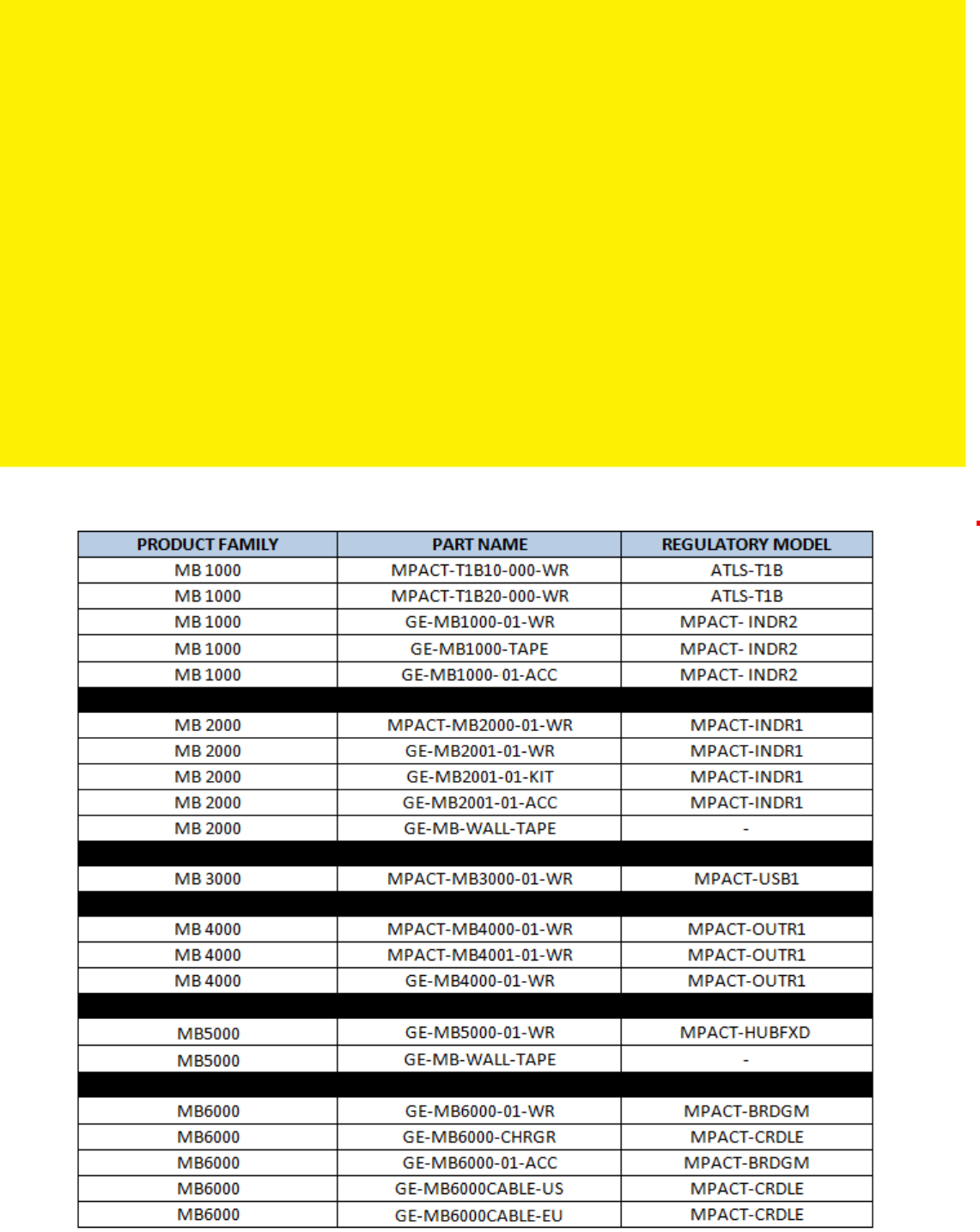
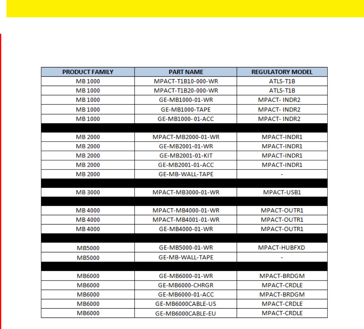
This guide supports the following product families, parts and regulatory models:

7
Using the Documentation
The following sections provide information about the document and notational conventions used in the guides, and provides a
list of related documentation.
Document Conventions
The following conventions are used in this manual to draw your attention to important information:
Revision History
This guide has the following release and revision milestone history:July
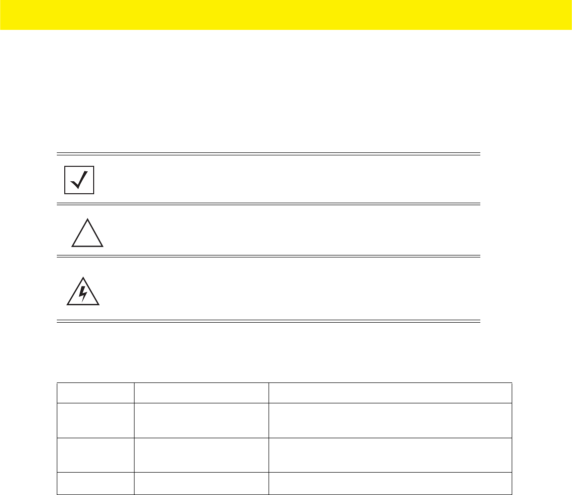
NOTE: Indicates tips or special requirements.
CAUTION: Indicates conditions that can cause equipment damage or data loss.
WARNING! Indicates a condition or procedure that could result in personal
injury or equipment damage.
Release Date Change
Revision A July, 2015 Initial release of document with new MPact beacons
added.
Revision A
(new baseline)
February, 2016 Outdoor beacon added. New Zebra template utilized.
Regulatory Draft July 2016 GE version beacons and accessories added.
!

8 MPact Location & Analytics Hardware Installation Guide
Notational Conventions
The following notational conventions are used in this document:
• Italics are used to highlight specific items in the general text, and to identify chapters and sections in this and related
documents
• Bullets (•) indicate:
• lists of alternatives
• lists of required steps that are not necessarily sequential
• action items
• Sequential lists (those describing step-by-step procedures) appear as numbered lists
Related Documentation
MPact Location and Analytics documentation includes the following:
• MPact Location & Analytics Deployment Guide
• MPact Location & Analytics Server Reference Guide
• MPact Location & Analytics Android Toolbox User Guide
• MPact Location & Analytics iOS Toolbox User Guide
• MPact Location & Analytics Client Software Development Kit
• MPact Location & Analytics Server API Reference Guide
• MPact Location & Analytics Hardware Installation Guide

9
Zebra Technologies Corporation ("Zebra") End-User Software License
Agreement
BY INSTALLING AND/OR USING THIS PRODUCT, YOU ACKNOWLEDGE THAT YOU HAVE READ THIS AGREEMENT,
UNDERSTAND IT AND AGREE TO BE BOUND ITS TERMS. IF YOU DO NOT AGREE TO THE TERMS OF THIS AGREEMENT, ZEBRA
IS NOT WILLING TO LICENSE THE PRODUCT TO YOU, AND YOU MUST NOT INSTALL OR USE THIS PRODUCT.
Definitions
Grant of License
Zebra Technologies Corporation ("Zebra") grants you ("Licensee" or "you") a personal, nonexclusive, nontransferable, revocable,
nonassignable, limited license to use the software and documentation ("Product(s)") subject to the terms and conditions of this
Agreement. You shall use the Products only for your internal business purposes, exclusively to support Zebra devices. Any use
of the Products outside of the conditions set forth herein is strictly prohibited and will be deemed a breach of this Agreement
resulting in immediate termination of your License. In the event of a breach of this Agreement, Zebra will be entitled to all
available remedies at law or in equity (including immediate termination of the license without notice, immediate injunctive
relief and repossession of all Products unless Licensee is a Federal agency of the United States Government).
You shall not distribute, sublicense, rent, loan, lease, export, re-export, resell, ship or divert or cause to be exported, re-
exported, resold, shipped or diverted, directly or indirectly, the Products under this Agreement. You shall not, and shall not
permit others to: (i) modify, translate, decompile, bootleg, reverse engineer, disassemble, or extract the inner workings of the
Products, (ii) copy the look-and-feel or functionality of the Products; (iii) remove any proprietary notices, marks, labels, or logos
from the Products; (iv) rent or transfer all or some of the Products to any other party without Zebra's prior written consent; or
(v) utilize any computer software or hardware which is designed to defeat any copy protection device, should the Products be
equipped with such a protection device.
Title to all copies of Products will not pass to Licensee at any time and remains vested exclusively in Zebra. All intellectual
property developed, originated, or prepared by Zebra in connection with the Products remain vested exclusively in Zebra, and
this Agreement does not grant to Licensee any intellectual property rights.
Portions of the Products are protected by United States patent and copyright laws, international treaty provisions, and other
applicable laws. Therefore, you must treat the Products like any other copyrighted material (e.g., a book or musical recording)
except that you may make one copy of the Product solely for back-up purposes. Unauthorized duplication of the Products
constitutes copyright infringement, and in the United States is punishable in federal court by fine and imprisonment.
Limited Warranty
Zebra warrants for a period of ninety (90) days from your receipt of the Products to you that the Software, under normal use,
will perform substantially in accordance with Zebra's published specifications for that release level of the Software. The
written materials are provided "AS IS" and without warranty of any kind. Zebra's entire liability and your sole and exclusive
remedy for any breach of the foregoing limited warranty will be, at Zebra's option, the provision of a downloadable patch or
replacement code, or a refund of the unused portion of your bargained for contractual benefit up to the amount paid for the
Products.
Disclaimer
THIS LIMITED WARRANTY IS THE ONLY WARRANTY PROVIDED BY ZEBRA, AND ZEBRA MAKES, AND YOU RECEIVE, NO
OTHER WARRANTIES OF ANY KIND, WHETHER EXPRESS, IMPLIED, STATUTORY, OR IN ANY COMMUNICATION WITH YOU.
ZEBRA SPECIFICALLY DISCLAIMS ANY WARRANTY INCLUDING THE IMPLIED WARRANTIES OF MERCHANTABILTY,
NONINFRINGEMENT, OR FITNESS FOR A PARTICULAR PURPOSE. ZEBRA DOES NOT WARRANT THAT THE PRODUCTS WILL
MEET YOUR REQUIREMENTS, OR THAT THE OPERATION OF THE PRODUCTS WILL BE UNINTERRUPTED OR ERROR FREE, OR
THAT DEFECTS IN THE PRODUCTS WILL BE CORRECTED. ZEBRA MAKES NO WARRANTY WITH RESPECT TO THE

10 MPact Location & Analytics Hardware Installation Guide
CORRECTNESS, ACCURACY, OR RELIABILITY OF THE PRODUCTS. Some jurisdictions do not allow the exclusion of implied
warranties, so the above exclusion may not apply to you.
Limitation of Liability
THE TOTAL LIABILITY OF ZEBRA UNDER THIS AGREEMENT FOR DAMAGES SHALL NOT EXCEED THE FAIR MARKET VALUE OF
THE PRODUCTS LICENSED UNDER THIS AGREEMENT. IN NO EVENT WILL ZEBRA BE LIABLE IN ANY WAY FOR INCIDENTAL,
CONSEQUENTIAL, INDIRECT, SPECIAL OR PUNITIVE DAMAGES OF ANY NATURE, INCLUDING WITHOUT LIMITATION, LOST
BUSINESS PROFITS, OR LIABILITY OR INJURY TO THIRD PERSONS, WHETHER FORESEEABLE OR NOT, REGARDLESS OF
WHETHER ZEBRA HAS BEEN ADVISED OF THE POSSIBILITY OF SUCH DAMAGES. Some jurisdictions do not permit limitations
of liability for incidental or consequential damages, so the above exclusions may not apply to you. This Limitation of Liability
provision survives the termination of this Agreement and applies notwithstanding any contrary provision in this Agreement.
Licensee must bring any action under this Agreement within one (1) year after the cause of action arises.
Maintenance
Unless provided for in a separate agreement, Zebra shall not be responsible for maintenance or field service of the Products.
High Risk Activities
The Products are not fault-tolerant and are not designed, manufactured or intended for use or resale as on-line control software
in hazardous environments requiring fail-safe performance, such as in the operation of nuclear facilities, aircraft navigation or
communication systems, air traffic control, direct life support machines, or weapons systems, in which the failure of the
Products could lead directly to death, personal injury, or severe physical or environmental damage ("High Risk Activities"). Zebra
and its suppliers specifically disclaim any express or implied warranty of fitness for High Risk Activities, and if you elect to use
the Products in any High Risk Activities, you agree to indemnify, defend, and hold Zebra harmless from and against any and all
costs, damages, and losses related to that use.
U.S. Government
If you are acquiring the Products on behalf of any unit or agency of the U.S. Government, the following shall apply. Use,
duplication, or disclosure of the Products is subject to the restrictions set forth in subparagraphs (c) (1) and (2) of the Commercial
Computer Software - Restricted Rights clause at FAR 52.227-19 (JUNE 1987), if applicable, unless being provided to the
Department of Defense. If being provided to the Department of Defense, use, duplication, or disclosure of the Products is
subject to the restricted rights set forth in subparagraph (c) (1) (ii) of the Rights in Technical Data and Computer Software clause
at DFARS 252.227-7013 (OCT 1988), if applicable. Products may or may not include a Restricted Rights notice, or other notice
referring specifically to the terms and conditions of this Agreement. The terms and conditions of this Agreement shall each
continue to apply, but only to the extent that such terms and conditions are not inconsistent with the rights provided to you
under the aforementioned provisions of the FAR and DFARS, as applicable to the particular procuring agency and procurement
transaction.
Assignment
Except as otherwise provided in this section, neither party may assign this Agreement, or any of its rights or obligations under
this Agreement, without the prior written approval of the other party, which will not be unreasonably withheld. Any attempted
assignment, delegation, or transfer without the necessary approval will be void. Notwithstanding the foregoing, for any Zebra
acquisition, merger, consolidation, reorganization, or similar transaction, or any spin-off, divestiture, or other separation of a
Zebra business, Zebra may, without the prior written consent of the other party: (i) assign its rights and obligations under this
Agreement, in whole or in part, or (ii) split and assign its rights and obligations under this Agreement so as to retain the benefits
of this Agreement for both Zebra and the assignee entity(ies) (and their respective Affiliates) following the split.

11
Governing Law
This Agreement shall be governed by the laws of the United States of America to the extent that they apply and otherwise by
the laws of the State of New York without regard to its conflict of laws provisions or by the internal substantive laws of the
country to which the Products is shipped if end-user customer is a sovereign governmental entity. The terms of the U.N.
Convention on Contracts for the International Sale of Goods do not apply. In the event that the Uniform Computer information
Transaction Act, any version of this Act, or a substantially similar law (collectively "UCITA") becomes applicable to a Party's
performance under this Agreement, UCITA does not govern any aspect of this End User License Agreement or any license
granted under this End-User License Agreement, or any of the parties' rights or obligations under this End User License
Agreement. The governing law will be that in effect prior to the applicability of UCITA.
Compliance with Laws
Licensee will comply with all applicable laws and regulations, including export laws and regulations of the United States.
Licensee will not, without the prior authorization of Zebra and the appropriate governmental authority of the United States, in
any form export or re-export, sell or resell, ship or reship, or divert, through direct or indirect means, any item or technical data
or direct or indirect products sold or otherwise furnished to any person within any territory for which the United States
Government or any of its agencies at the time of the action, requires an export license or other governmental approval. Violation
of this provision will be a material breach of this Agreement, permitting immediate termination by Zebra.
Third Party Software
The Products may contain one or more items of Third-Party Software. The terms of this Agreement govern your use of any Third-
Party Software UNLESS A SEPARATE THIRD-PARTY SOFTWARE LICENSE IS INCLUDED, IN WHICH CASE YOUR USE OF THE
THIRD-PARTY SOFTWARE WILL THEN BE GOVERNED BY THE SEPARATE THIRD-PARTY LICENSE.
Open Source Software
The Products may contain one or more items of Open Source Software. Open Source Software is software covered by a publicly
available license governed solely under Copyright law, whereas the complete terms and obligations of such license attach to
a licensee solely through the act of copying, using and/or distribution of the licensed software, such obligations often include
one or more of attribution obligations, distribution obligations, copyleft obligations, and intellectual property encumbrances.
The use of any Open Source Software is subject to the terms and conditions of this Agreement as well as the terms and
conditions of the corresponding license of each Open Source Software package. If there is a conflict between the terms and
conditions of this Agreement and the terms and conditions of the Open Source Software license, the applicable Open Source
Software license will take precedence. Copies of the licenses for the included Open Source Software, if any, as well as their
attributions, acknowledgements, and software information details, are provided in the electronic copy of this Agreement,
which is available in the Legal Notices or README file associated with the Product. Zebra is required to reproduce the software
licenses, acknowledgments and copyright notices as provided by the authors and owners, thus, all such information is provided
in its native language form, without modification or translation. Depending on the license terms of the specific Open Source
Software, source code may not be provided. Please reference and review the entire Open Source Software information to
identify which Open Source Software packages have source code provided or available. For instructions on how to obtain a
copy of any source code made publicly available by Zebra related to Open Source Software distributed by Zebra, you may send
your request (including the Zebra Product name and version, along with the Open Source Software specifics) in writing to: Zebra
Technologies Corporation, Open Source Software Director, Legal Department, 3 Overlook Point, Lincolnshire, IL 60069 USA.
©2015 ZIH Corp and/or its affiliates. All rights reserved. Zebra and the stylized Zebra head are trademarks of ZIH Corp.,
registered in many jurisdictions worldwide. All other trademarks are the property of their respective owners.

12 MPact Location & Analytics Hardware Installation Guide

CHAPTER 1 MPACT BLUETOOTH®
SMART BEACON OVERVIEW
MPact utilizes Bluetooth® Smart beacons in various modes to unify Wi-Fi and Bluetooth® Smart Technology to capture
analytics, accuracy and insight.
Beacon placements can be adjusted within a deployment floor plan, and depending on the mode selected, their battery life can
be tracked over time. Administrators can cursor over a beacon on a site’s floor plan to assess the beacon’s remaining battery
life. This guide covers a variety of indoor, outdoor and USB type beacons, mounting options, and operational instructions for
each beacon type.
This guide includes the following:
•Beacon Hardware Specifications and Installation
•MB1000 Beacon Part Number: MPACT-T1B20-000-WR
•MB1000 Beacon Part Number: MPACT-T1B10-000-WR
•MPACT-INDR1: MPACT-MB2000-01-WR, GE-MB2001-01-WR MPACT-INDR2: GE-MB1000-01-WR
•Beacon Battery Replacement
•USB Beacon Part Number: MPACT-MB3000-01-WR
•Beacon Part Numbers: MPACT-MB4000-01-WR, MPACT-MB4001-01-WR, GE-MB4000-01-WR and GE-MB4001-01-WR
•Beacon Part Number: GE-MB1000-01-WR
•Beacon Part Number: GE-MB2001-01-WR
•Initializing a GE-MB5000-01-WR Hub
•Beacon Part Number: GE-MB6000-01-WR Badge
•Cradle Charger: MPACT-MB6000-CHRGR
1 - 2 MPact Location & Analytics Hardware Installation Guide
1.1 Product and Part Compatibility Matrix
This guide supports the following product families, parts and regulatory models:
Figure 1-1 Product and Part Compatibility

CHAPTER 2 BEACON HARDWARE
SPECIFICATIONS AND INSTALLATION
The following setup processes must be completed as a prerequisite to installing beacon hardware:
•MPact Server Installation and Setup - see the MPact Location & Analytics Deployment Guide
•MPact Toolbox and Beacon Installation - see the MPact Toolbox User Guides
The guides are available at www.zebra.com/support.
Lozier® Shelves
Beacon brackets for the MPACT-T1B20-000-WR and MPACT-T1B10-000-WR are used with the following Lozier products:
• TL Shelf
•DL Shelf
•HL Shelf
• Standard Base Deck
2.1 MB1000 Beacon Part Number: MPACT-T1B20-000-WR
As a prerequisite, the following hardware items are required to mount the tie-wrap style beacon housing to a pole or similar
structure:
• Beacon (tie-wrap style housing), part number - MPACT-T1B20-000-WR. (When ordering, use part number: MPACT-T1B20-
250-WR (box of 25).
• Plastic tie wraps for attaching each beacon housing to the shelf
2 - 2 MPact Location & Analytics Hardware Installation Guide
2.1.1 Installing the Tie-Wrap Style Beacon
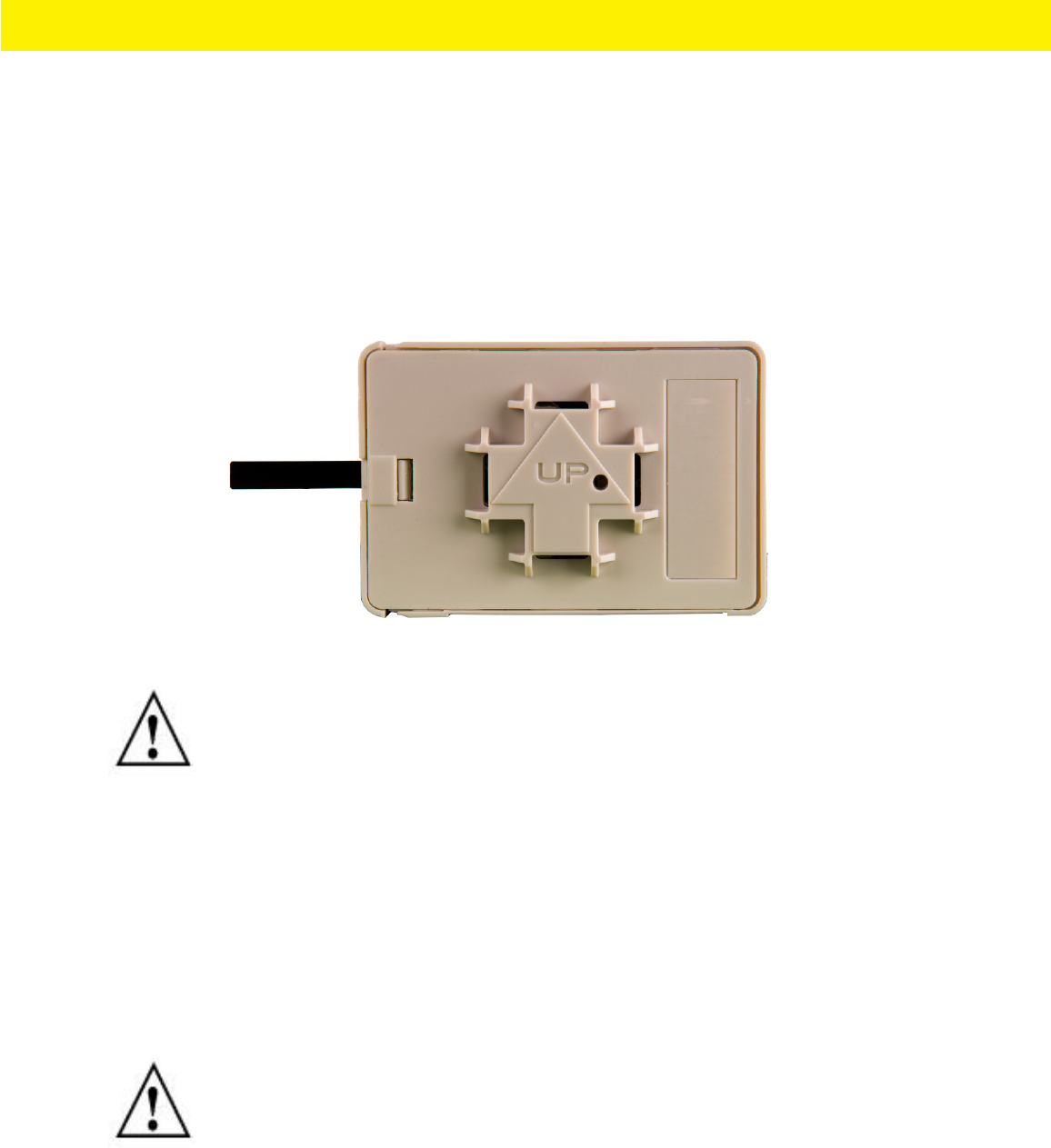
Tie-wrap beacon housings are designed to attach to vertical or horizontal poles or similar mounting surfaces. In Figure 2-1, there
are openings on the back of the beacon housing allowing a tie wrap through the openings and wrapped around a pole or similar
structure.
Notice the up arrow located on the middle of the beacon housing. This arrow indicates the optimal orientation for the beacon
to function properly. Additionally, the smooth front of the beacon should face outward toward the aisle where client devices
are expected to engage (dwell).
Figure 2-1 shows a beacon with the mylar strip attached to the left-hand side of the housing.
Figure 2-1 Tie Wrap Style Beacon - Part Number - MPACT-T1B20-000-WR
From MPact the Toolbox, select a site floor plan and an unassigned position for the beacon. Refer to the MPact Location &
Analytics Deployment Guide for information on how to install and deploy the beacon from the Toolbox.
To mount the tie wrap beacon to a pole or similar structure:
• Mount the beacon to a pole or similar structure using the plastic tie wrap. Tie can be placed vertically or horizontally but
the arrow should still point up.
To activate a beacon part number - MPACT-T1B20-000-WR:
• Activate one or more beacons by pulling the mylar strip off the beacon housing.
NOTE: When installing numerous beacons, group beacons by category and activate them
prior to scanning the barcodes and associating them with positions in the Toolbox.
CAUTION: After pulling off the last mylar strip, you have 20 seconds to associate the
beacon in either offline or online mode using the Toolbox application.
Beacon Hardware Specifications and Installation 2 - 3
Beacon Hardware Specifications and Installation 2 - 3
2.2 MB1000 Beacon Part Number: MPACT-T1B10-000-WR
As a prerequisite, the following hardware items are required to mount beacon brackets to a Lozier style shelf:
•Lozier® Shelves
• Beacon: Part number - MPACT-T1B10-000-WR
• When ordering, use the following part number: MPACT-T1B10-250-WR (box of 25)
• Bracket mount, one of the following:
• MPACT Metal Lozier Bracket: Part number MPACT-A1O10-004-WR
• MPACT Plastic Lozier Bracket: Part number MPACT-A1O10-001-WR
• Phillips head screw driver for mounting the bracket (metal brackets only) to the Lozier shelf
2.2.1 Mounting and Installing the Universal Style Beacon
Figure 2-2 shows a universal style beacon. While there is no up arrow on this beacon’s housing, the beacon should be oriented
similar to the tie wrap style of beacon housing, see MB1000 Beacon Part Number: MPACT-T1B20-000-WR.
Notice the up arrow located on the middle of the beacon housing. This arrow indicates the optimal orientation for the beacon
to function properly. Additionally, the smooth front of the beacon should face outward toward the aisle where client devices
are expected to engage (dwell).
Figure 2-2 Universal Style Beacon - Part Number - MPACT-T1B10-000-WR
From the MPact Toolbox, select a site floor plan and an unassigned position for the beacon. Refer to the MPact Location &
Analytics Deployment Guide for information on how to install and deploy the beacon from the Toolbox.
The guides are available at www.zebra.com/support.
NOTE: When installing numerous beacons, group beacons by category configurations
and activate the beacons prior to scanning the barcodes and associating them with
positions in the Toolbox.
2 - 4 MPact Location & Analytics Hardware Installation Guide
To mount the universal style beacon to Lozier® Shelves:
1. Mount the universal beacon shelf-bracket on the shelf:
•Metal brackets: Fit in place and tighten onto the shelving unit using a phillips-head screw driver.
•Plastic brackets: Fit in place and snap onto the shelving unit.
2. Fit the beacon’s universal style housing into the bracket (mylar strip pointing up) and turn the beacon housing clockwise 90
degrees.
The barcode label should face up toward the ceiling and the smooth front of the beacon should face out toward the aisle
where the mobile client is expected to engage.
There are two styles of bracket mounts from which to choose, either metal or plastic for Beacon:
Part number - MPACT-T1B10-000-WR.
Figure 2-3 Universal Style Metal Bracket - Part Number MPACT-A1O10-004-WR
Figure 2-4 Universal Style Plastic Bracket with Beacon- Bracket Part Number MPACT-A1O10-001-WR
Beacon Hardware Specifications and Installation 2 - 5
Beacon Hardware Specifications and Installation 2 - 5
Activate one or MPACT-T1B10-000-WR model beacons by pulling the mylar strip off the beacon housing.
2.2.2 Beacon Battery Replacement
When a beacon’s battery life is less than 20%, the beacon should be prioritized for immediate replacement. The beacon’s
battery is located within a battery tray in the beacon’s housing.
This section includes procedures for replacing batteries for the following part numbers:
•Replacing MB1000 Battery: MPACT-T1B20-000-WR and MPACT-T1B10-000-WR
2.2.2.1 Replacing MB1000 Battery: MPACT-T1B20-000-WR and MPACT-T1B10-000-WR
MPACT-T1B20-000-WR and MPACT-T1B10-000-WR beacon battery:
1. Remove the beacon from the shelving unit.
2. With the bottom of the beacon facing up, gently lift each corner of the beacon’s battery tray.
Figure 2-5 shows the beacon battery housing for part number MPACT-T1B20-000-WR and MPACT-T1B10-000-WR and
MPACT-T1B10-000-WR. In this example, the battery tray is on the right and the corners of the battery tray are marked in
red. When gently lifting each tray corner, slightly push the each corner out to dislodge corners of the tray.
Figure 2-5 Beacon Battery Housing Example: MPACT-T1B20-000-WR and MPACT-T1B20-000-WR and MPACT-T1B10-000-WR
3. With both tray corners dislodged, gently slide the battery tray open, being careful not to drop the tray.
Figure 2-6 shows an open battery housing. In this example, the battery tray is a separate piece, along with the battery, on
the right-hand side.
Figure 2-6 Battery Tray: MPACT-T1B20-000-WR and MPACT-T1B20-000-WR and MPACT-T1B10-000-WR
CAUTION: After pulling off the last mylar strip, you have 20 seconds to associate the
beacon in either offline or online mode using the Toolbox application.
2 - 6 MPact Location & Analytics Hardware Installation Guide
4. Remove the old battery, dispose properly, and replace with a Panasonic CR2450 model battery.
5. Close the tray, ensuring the latch is secure.
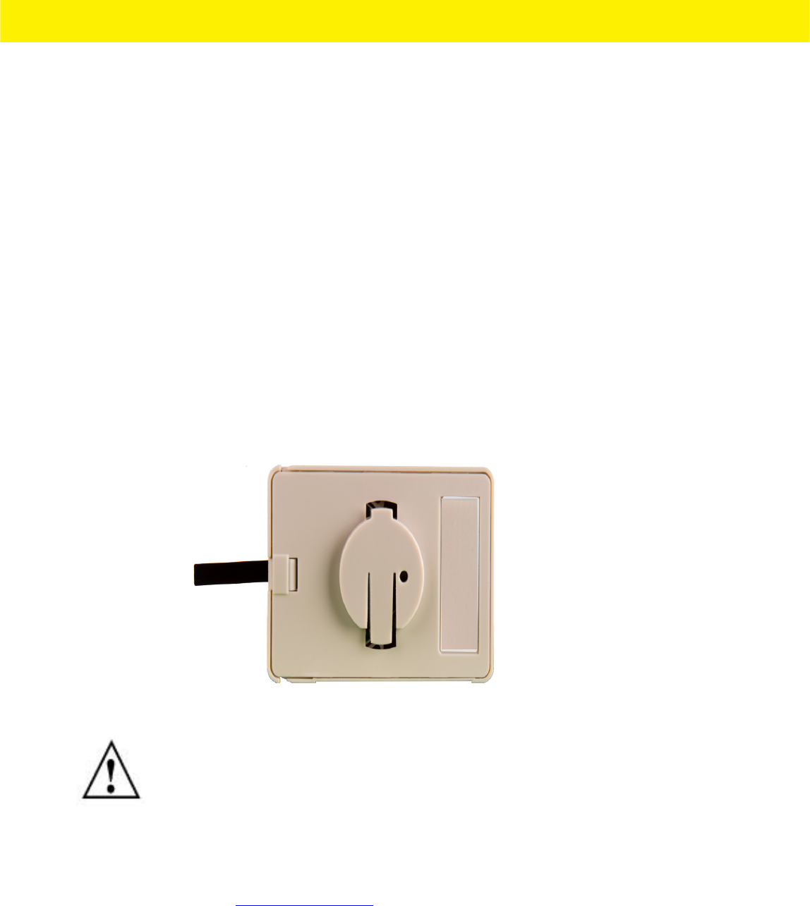
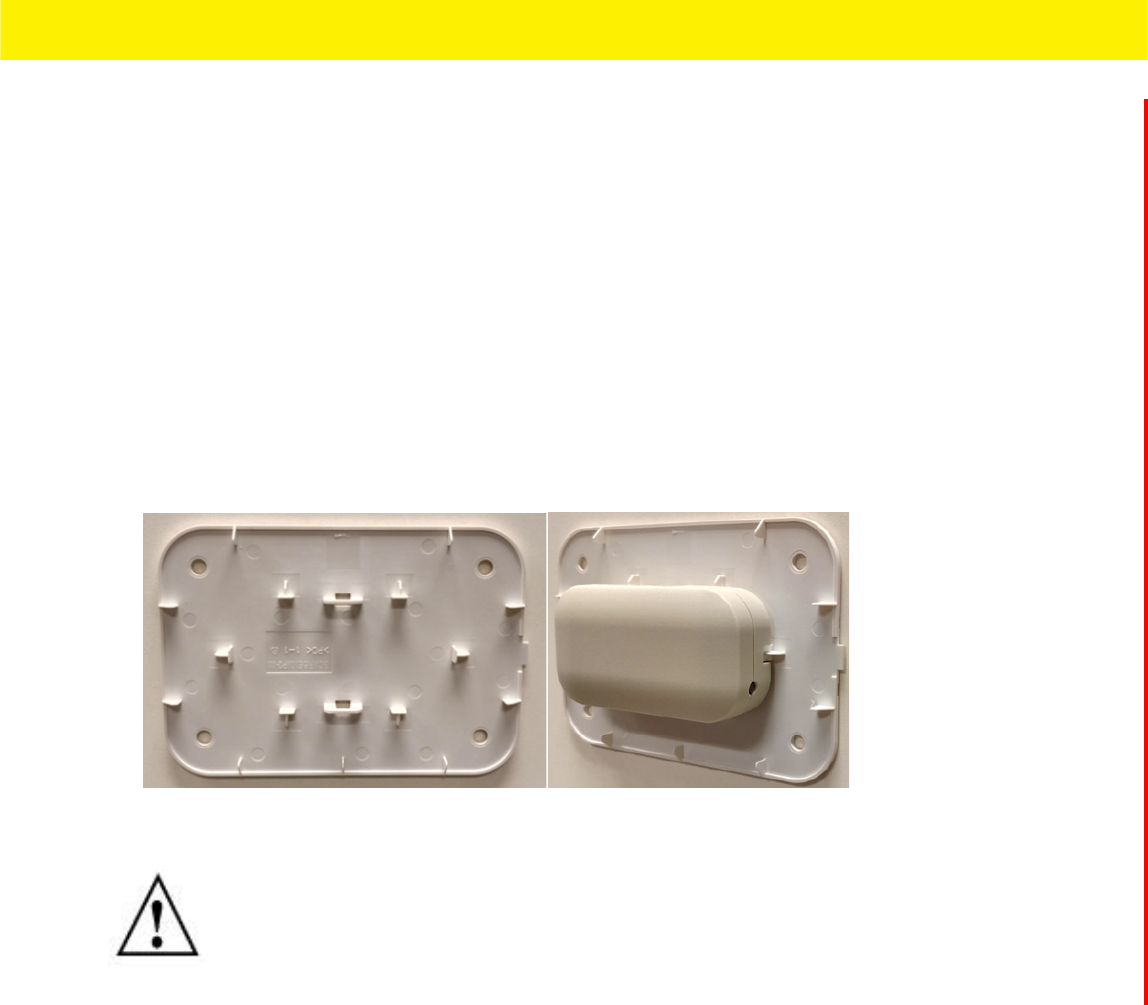
2.3 MPACT-INDR1: MPACT-MB2000-01-WR, GE-MB2001-01-WR
MPACT-INDR2: GE-MB1000-01-WR
As a prerequisite, the following hardware is required to wall mount a beacon:
• Beacon: Part numbers - MPACT-MB2000-01-WR and GE-MB2001-01-WR
• When ordering, use the following part number: MPACT-MB2000-01-WR (box of 25)
• Bracket mount kit see Figure 2-7 (included with part number MPACT-MB2000-01-WR):
• Metal bracket
• Two 1inch Phillips head tap screws, and two 1inch plastic wall inserts
2.3.1 Mounting and Installing the Indoor Style (MPACT-MB2000-01-WR) Beacon
1. From the MPact Toolbox, select a site floor plan and an unassigned position for the beacon. Refer to the MPact Location &
Analytics Deployment Guide for information on how to install and deploy the beacon from the Toolbox.
To mount the universal style beacon to a wall:
.a Mount the beacon wall bracket with the provided screws and plastic wall inserts.
.b Press the beacon’s housing onto the bracket as shown in Figure 2-7.
NOTE: Pay attention to the position of the + on the battery. Installing the battery
backwards may damage the Beacon
NOTE: The barcode label should face up toward the ceiling and the smooth front of the
beacon should face out toward the aisle where clients are expected to engage (dwell).
NOTE: When installing numerous beacons, group beacons by category configurations
and activate the beacons prior to scanning the barcodes and associating them with
positions in the Toolbox.
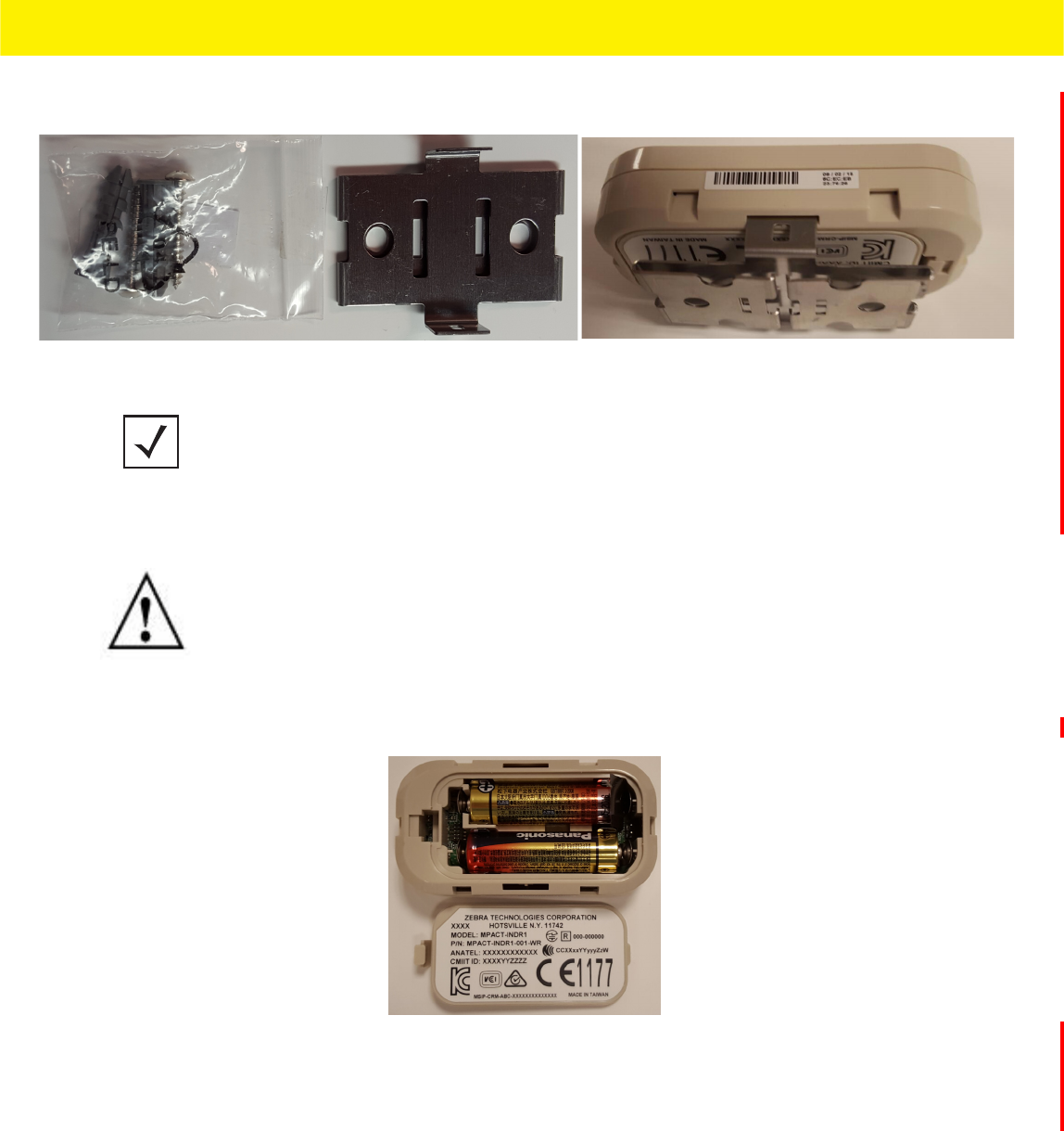
Beacon Hardware Specifications and Installation 2 - 7
Beacon Hardware Specifications and Installation 2 - 7
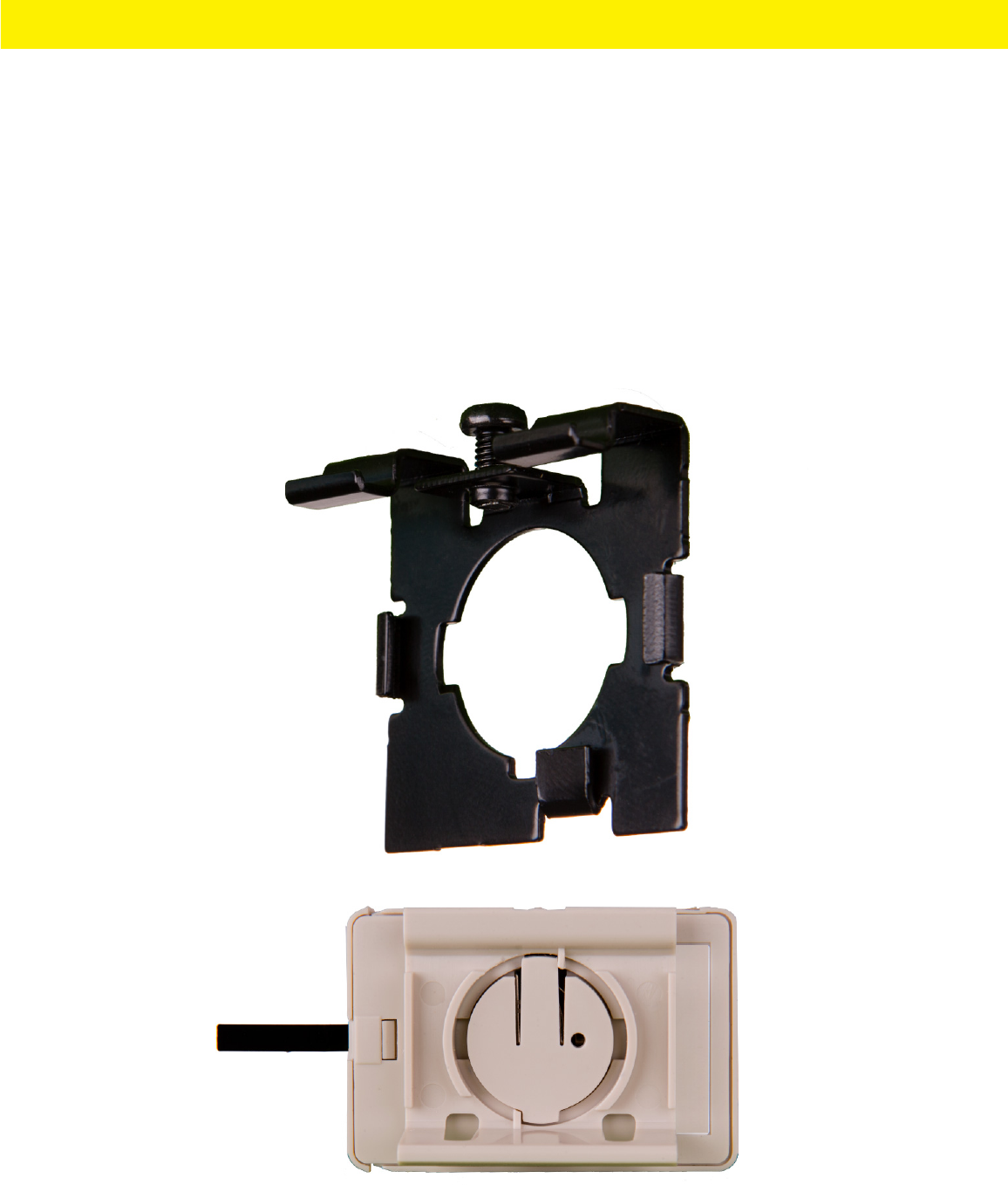
There is one style of bracket mount included with the Indoor Style Beacon: Part number - MPACT-MB2000-01-WR.
Figure 2-7 Metal Beacon Wall Mount Bracket: MPACT-MB2000-01-WR
2. Activate one or more MPACT-MB2000-01-WR beacons by pulling the mylar strip out from inside the beacon housing.
Phillips head screw driver for mounting the bracket (metal brackets only) to a wall
Figure 2-8 Indoor Style Beacon - MPACT-MB2000-01-WR
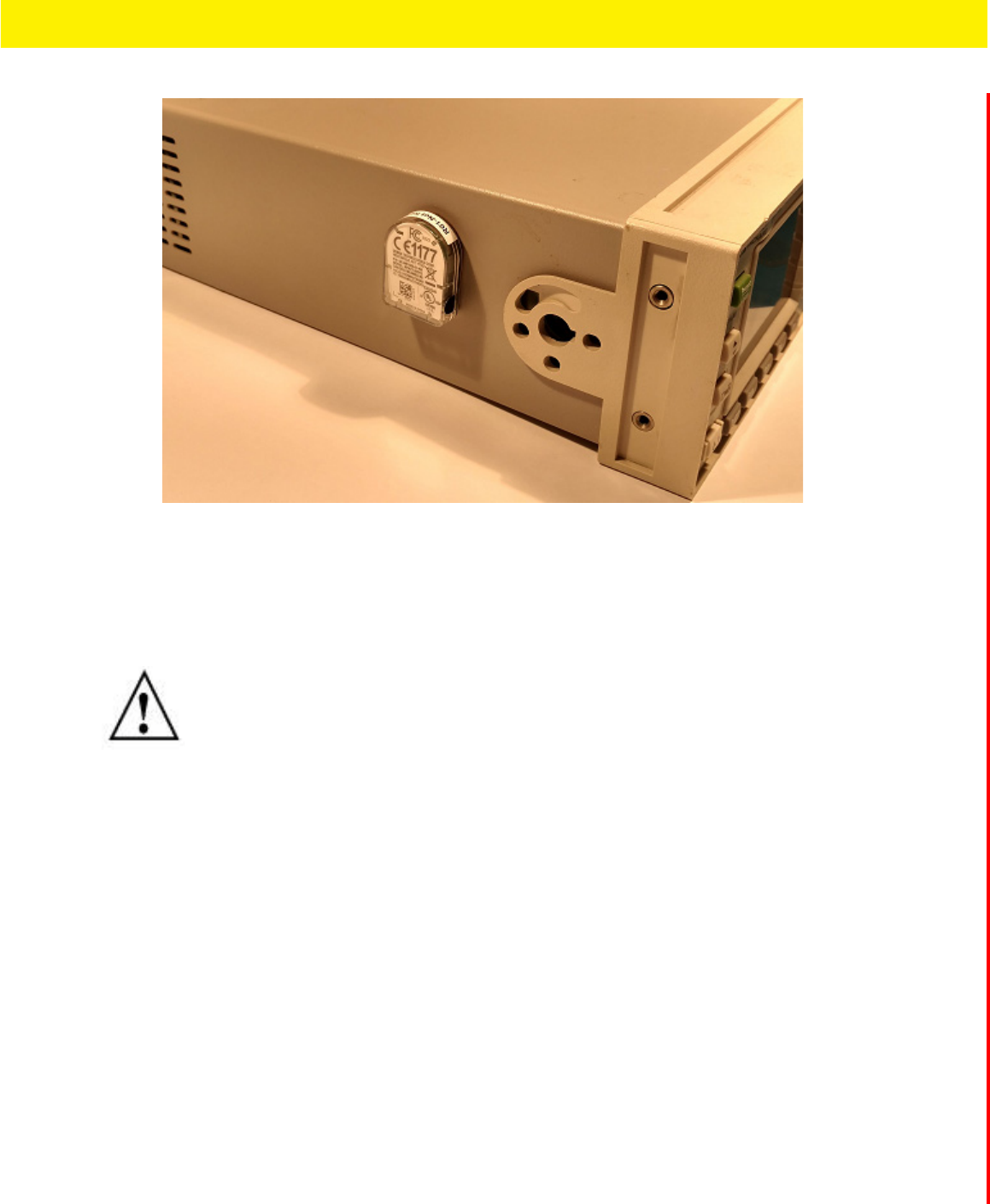
2.3.2 Mounting and Installing a GE-MB2001-01-WR (TBD)
To mount a GE- MB2001-01-WR model beacon:
NOTE: Ensure the beacon is positioned correctly, Once the beacon is mounted on the
bracket it will be difficult to remove.
CAUTION: After pulling off the last mylar strip, you have 20 seconds to associate the
beacon in either offline or online mode using the Toolbox application.

2 - 8 MPact Location & Analytics Hardware Installation Guide
Figure 2-9 GE-MB2001-01-WR Cover and Wall Mount
Beacon Hardware Specifications and Installation 2 - 9
Beacon Hardware Specifications and Installation 2 - 9
2.4 Beacon Operating Modes
Refer to the following for beacon operating modes for MPACT-MB2000-01-WR, GE-MB2000-01-WR and
GE-MB1000-01-WR model beacons:
Refer to the following for Indoor Style Beacon operating modes:
2.5 Beacon Battery Replacement
When a beacon’s battery life is less than 20%, the beacon should be prioritized for immediate replacement. The beacon’s
battery is located within a battery tray in the beacon’s housing.
This section includes procedures for replacing batteries for the following:
•Replacing Battery: MPACT-MB2000-01-WR and GE-MB2001-01-WR
2.5.1 Replacing Battery: MPACT-MB2000-01-WR and GE-MB2001-01-WR
To replace a beacon’s battery in part number MPACT-MB2000-01-WR and GE-MB2001-01-WR:
1. Remove the beacon from the shelving unit (see information on the appropriate beacon part number).
2. With the bottom of the beacon facing up, use your finger nail to gently lift the clip up to remove the back off the beacon’s
battery enclosure.
3. Remove the old batteries and dispose of properly and replace it with two new 2AA batteries.
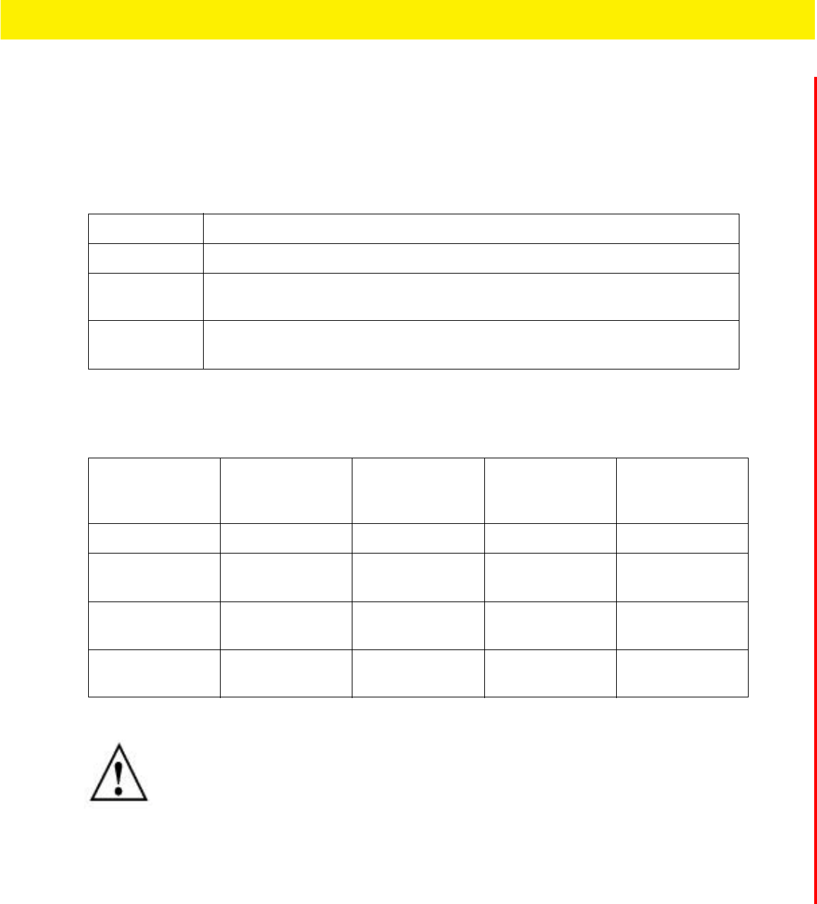
Mode Definition
Sleep The beacon is not transmitting or accepting client connections.
Configuration The beacon accepts connections from clients. Clients can configure the device when connected.
Broadcast The beacon is transmitting packets that conform to one of the supported beacon formats (iBeacon,
MPact, Battery Save and SecureCast).
Mode Sleep Configuration Broadcast LED Behavior
0-2 seconds No action No action No action
2+ -5 Broadcast Broadcast Broadcast Slow flash when
button flashes 300
ms on / 300ms off.
5+ - 10 Move to
configuration
Remain in
configuration
Move to
configuration
Fast flash – 100ms
/on & off
+ 10 Sleep Sleep Sleep Solid light
NOTE: Pay attention to the polarity (+ and -) of the batteries. Installing the batteries
incorrectly may damage the Beacon.
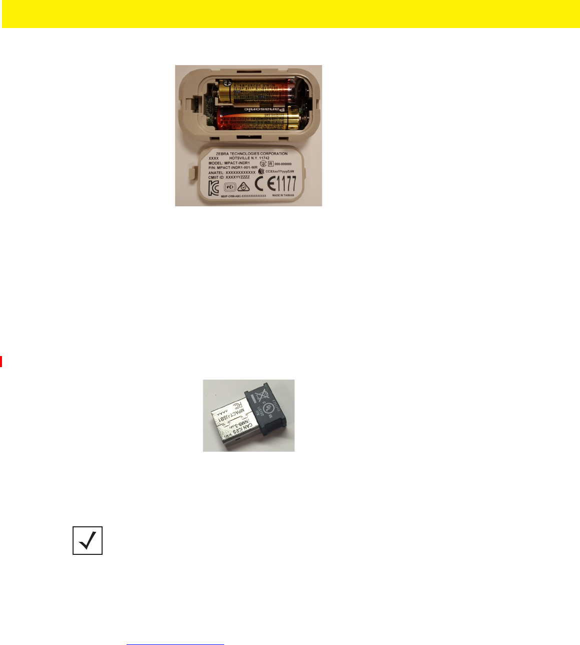
2 - 10 MPact Location & Analytics Hardware Installation Guide
Figure 2-10 Open Battery Enclosure: MPACT-MB2000-01-WR
4. Close the battery enclosure, ensuring the clip is secure.
2.6 USB Beacon Part Number: MPACT-MB3000-01-WR
A USB powered interface is required to power the USB Beacon. No additional hardware is required.
2.6.1 Installing the USB Style Beacon
To activate a MPACT-MB3000-01-WR model beacon:
1. Insert the beacon into any standard USB power source. The beacon moves into connect mode automatically after insertion.
Figure 2-11 USB Style Beacon - MPACT-MB3000-01-WR
When installing numerous beacons, group beacons by category configurations and activate the beacons prior to scanning the
barcodes and associating them with positions in the Toolbox.
2. After inserting the beacon(s) into any standard USB power source, associate the beacon in either offline or online mode in
the Toolbox application.
3. From the MPact Toolbox, select a site floor plan and an unassigned position for the beacon. Refer to the MPact Location &
Analytics Deployment Guide for information on how to install and deploy the beacon from the Toolbox. The guides are
available at www.zebra.com/support.
NOTE: The USB beacon barcode is not on the beacon itself but on the on its plastic
packaging.
Beacon Hardware Specifications and Installation 2 - 11
Beacon Hardware Specifications and Installation 2 - 11
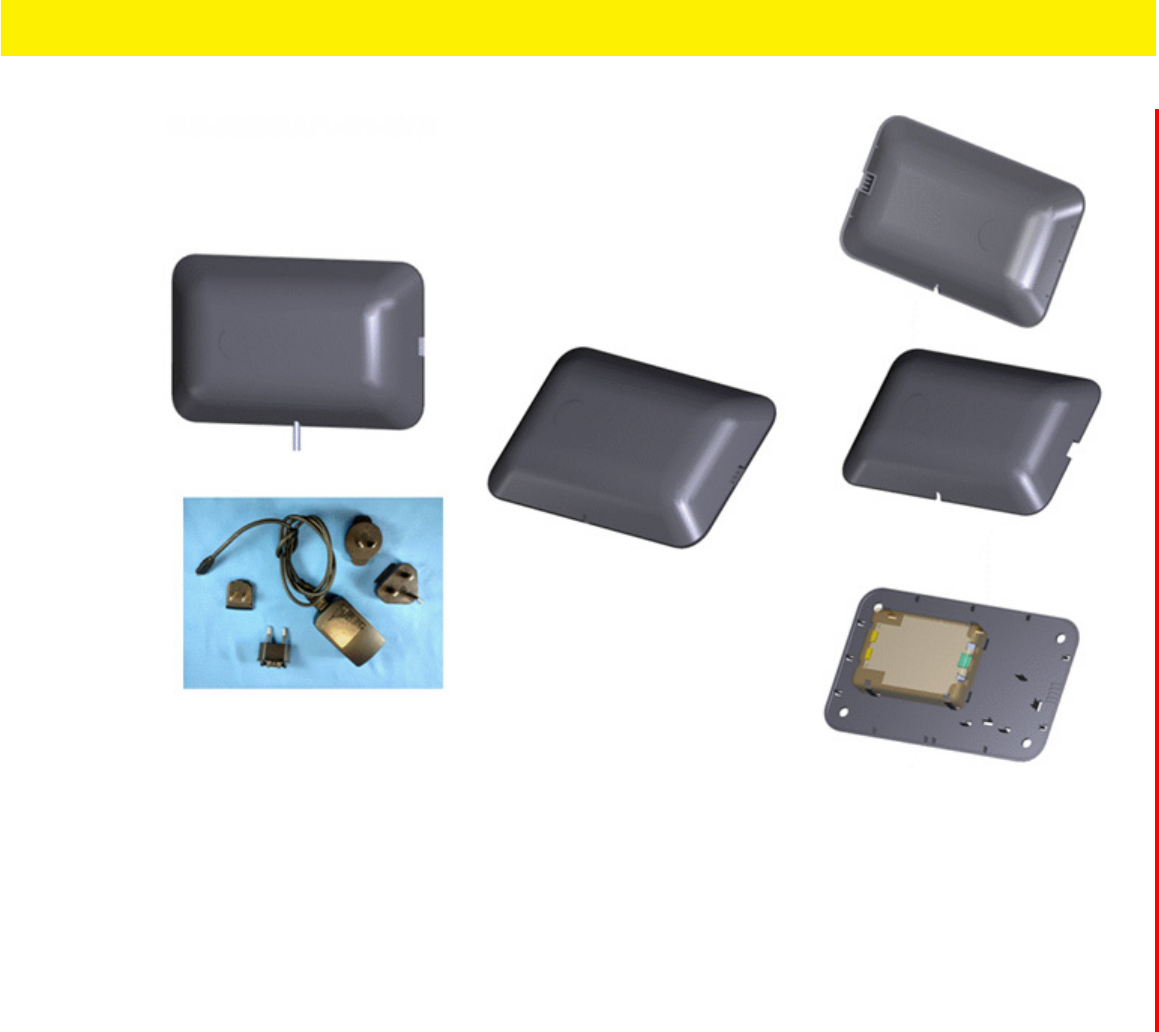
2.7 Beacon Part Numbers: MPACT-MB4000-01-WR, MPACT-MB4001-01-WR,
GE-MB4000-01-WR and GE-MB4001-01-WR
As a prerequisite, the following hardware items are required to mount a beacon.
• Beacon: Part numbers - MPACT-MB4000-01-WR
• Two No. 6 gauge or M3.5 screws (not included) for use on the intended surface
• Phillips head screw driver compatible with No. 6 gauge screws for mounting the Outdoor Style beacon
2.7.1 Antennae Positions
The following are antennae positions for the MPACT-MB4000-01-WR Outdoor Beacon:
• MPACT-MB4000-01-WR and GE-MB4000-01-WR orients its antenna down at a 20 degree angle
• MPACT-MB4001-01-WR orients its antenna down to the side at a 20 degree angle
Figure 2-12 Antennae Positions for the MPACT-MB4000-01-WR Beacon
2 - 12 MPact Location & Analytics Hardware Installation Guide
Figure 2-13 Antennae Positions for the GE-MB4000-01-WR Beacon (TBD)
2.7.2 Mounting and Installing the Outdoor Style Beacon
1. From the MPact Toolbox, select a site floor plan and an unassigned position for the beacon. Refer to the MPact Location &
Analytics Deployment Guide for information on how to install and deploy the beacon from the Toolbox.
To prepare the Outdoor style beacon for mounting:
.a Prepare a surface with 3M VHB double-sided tape. See section 2.7.2.1 Preparing Surface for Mounting with 3M VHB Double-
sided tape: on page 2-12.
Or
.b Prepare to mount the Outdoor style beacon with two No. 6 gauge or M3.5 screws (not included).
2.7.2.1 Preparing Surface for Mounting with 3M VHB Double-sided tape:
To prepare a surface before mounting the Outdoor style beacon to a wall with 3M VHB double-sided tape:
Clean the surface with a 50:50 mixture of isopropyl alcohol (IPA) and water before applying 3M™ VHB™ tape.
Some surfaces may require additional preparation such as the following:
• Use degreasers or solvent-based cleaner to remove heavy oil or grease from a surface followed by cleaning with IPA/water
• Scrape the surface, followed by cleaning with IPA/water to remove heavy dirt or oxidation and increases surface area to
improve adhesion.
• Prime the surface to improve initial and ultimate adhesion to many materials such as plastics and paints..
• Seal porous and fibered materials such as wood, particleboard, and concrete to provide a unified surface.
After preparing the surface the Outdoor Style beacon is now ready to be mounted.
NOTE: If the surface is clean and smooth, the 3M VHB tape should be used to mount the
beacon. However, is wood, brink or some other surface that is not smooth and clean, the
3M tape will not adhere to the surface. Use the appropriate screws for mounting (not
included). When using screws to mount to a surface, do not expose the 3M VHB tape.
Beacon Hardware Specifications and Installation 2 - 13
Beacon Hardware Specifications and Installation 2 - 13
2.7.2.2 Mounting Outdoor Style Beacon
To mount a Outdoor Style beacon with 3M™ VHB™ tape:
1. Peel the plastic off from 3M™ VHB™ tape.
2. Press the backside of the Outdoor Style beacon firmly to a smooth clean mounting surface.
To mount a Outdoor Style beacon with No. 6 gauge or M3.5 screws:
1. Press the backside of the beacon to the mounting surface.
2. Insert screws into the screw holes as shown in Figure 2-15 on page 2-13.
3. Hand tighten the screws to firmly secure the beacon.
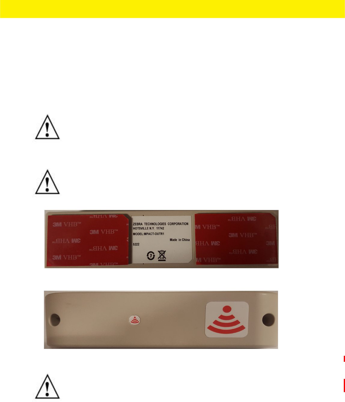
Figure 2-14 Back of Outdoor Style Beacon Outdoor Beacon
Figure 2-15 Top of Outdoor Style Beacon - MPACT-MB4000-01-WR
NOTE: Zebra recommends not removing the plastic backside of the 3M tape when
mounting the beacon with screws.
NOTE: Ensure the beacon is positioned correctly. Once the beacon is mounted it should
difficult to remove.
NOTE: On MPACT-MB4000-01-WR model outddor beacons, the red antenna pattern
indicates that the antenna is pointing down.
2 - 14 MPact Location & Analytics Hardware Installation Guide
2.7.2.3 Activating Outdoor Style Beacon
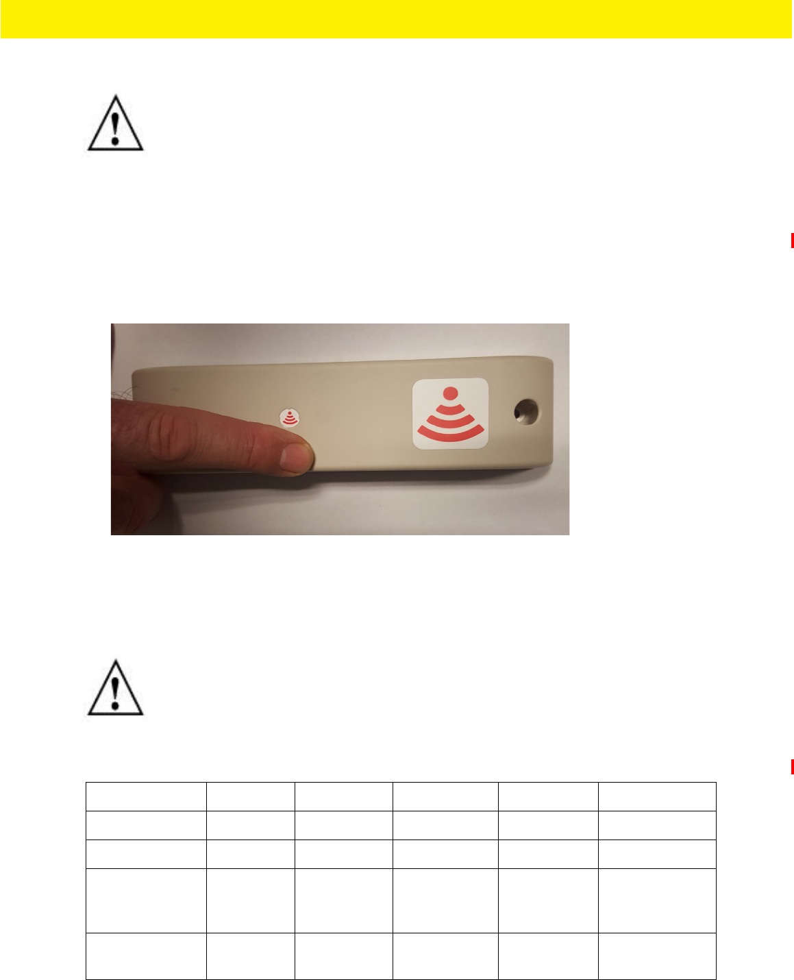
To activate a MPACT-MB4000-01-WR or GE-MB1000-01-WR model beacon:
1. Swipe your finger across the capacitive switch several times to wake the beacon out of shipping mode into broadcast mode.
The light becomes solid and then turns off.
Figure 2-16 Activating Outdoor Style Beacon - MPACT-MB4000-01-WR
To put the beacon part number - MPACT-MB4000-01-WR into connect mode:
1. Press your finger on the capacitive switch for about five seconds. The LED will flash slowly. Refer to the table below for
information about operating modes.
The barcode label should face up toward the ceiling and the smooth front of the beacon should face out to where the mobile
client is expected to engage.
NOTE: When installing numerous beacons, group beacons by category configurations
and activate the beacons prior to scanning the barcodes and associating them with
positions in the Toolbox.
NOTE: When installing numerous beacons, group beacons by category configurations
and activate the beacons prior to scanning the barcodes and associating them with
positions in the Toolbox.
Mode Shipping Sleep Configuration Broadcast LED Behavior
0-2 seconds No action No action No action No action
2+ -7 Broadcast Broadcast Broadcast Broadcast Solid light
7+ - 12 Move to
configuration
Remain in
configuration
Move to
configuration
Slow flash when
button flashes 300
ms on / 300ms off.
+ 12 Sleep Sleep Sleep Fast flash – 100ms
/on & off
Beacon Hardware Specifications and Installation 2 - 15
Beacon Hardware Specifications and Installation 2 - 15
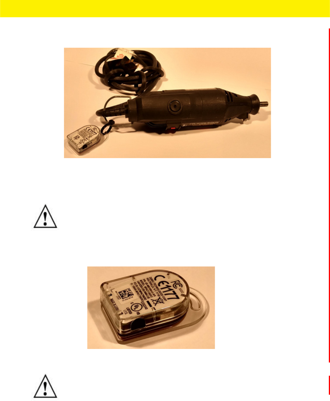
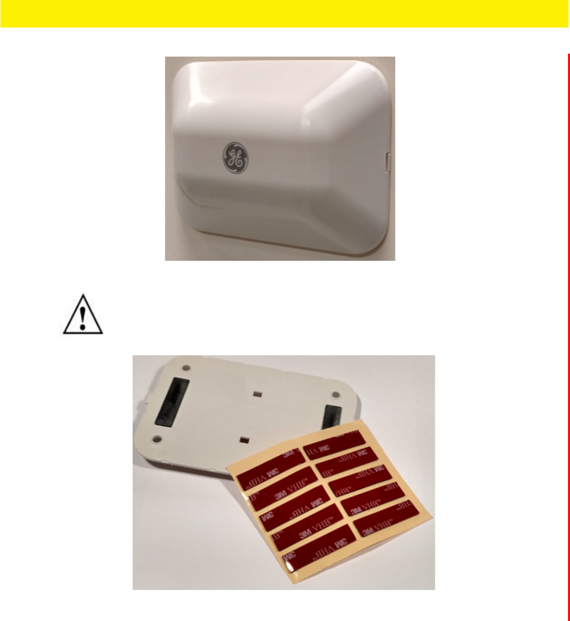
2.8 Beacon Part Number: GE-MB1000-01-WR
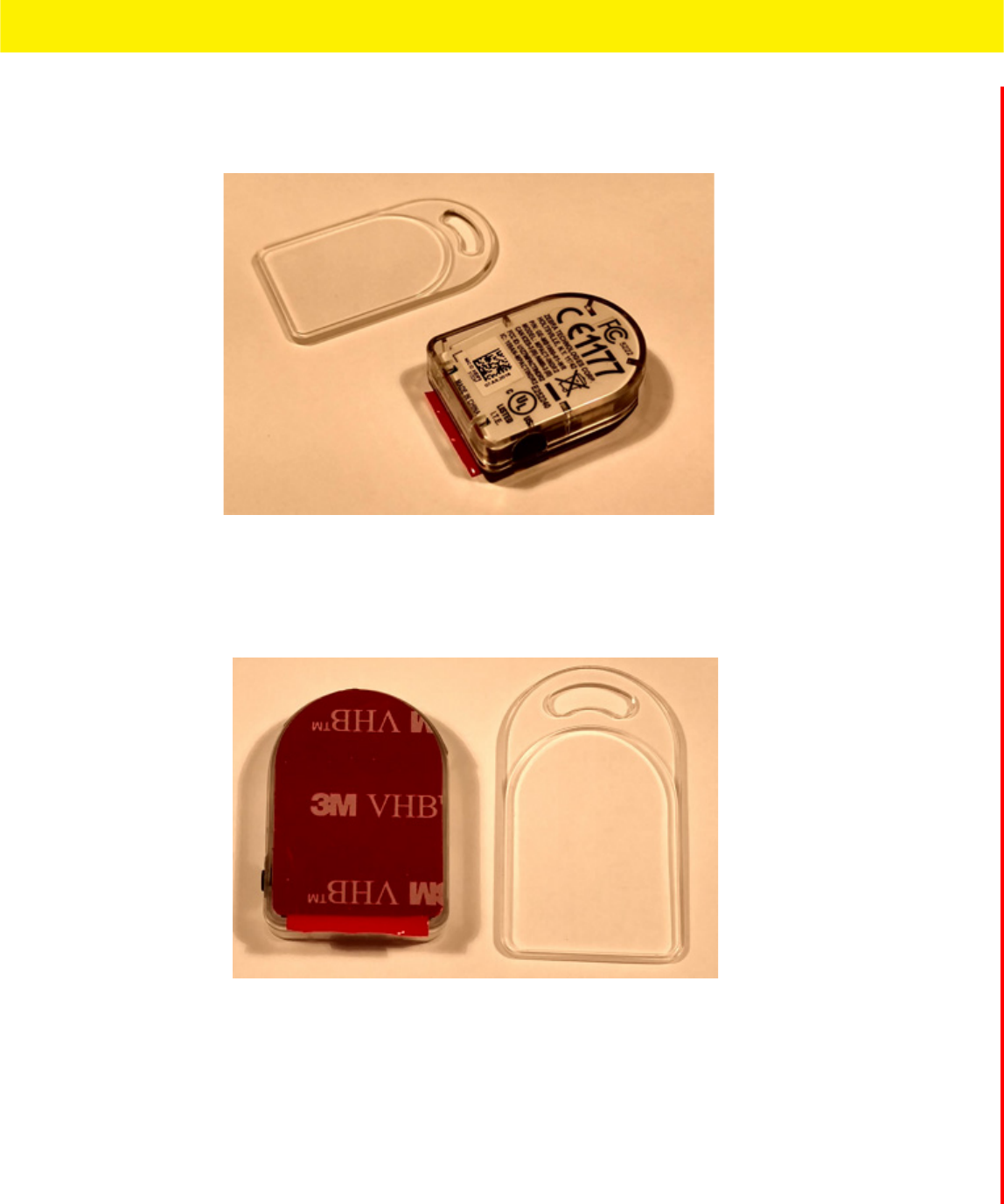
A GE-MB1000-01-WR beacon is a smaller beacon designed to be afixed to assets.
Figure 2-17 GE-MB1000-01-WR and Mounting Accessory
The above image depicts a GE-MB1000-01-WR asset beacon and the mounting accessory (GE-MB1000-01-ACC) used to attach
the asset beacon to an object lacking a flat mounting surface or space. On the side of the asset beacon is a switch used to
place the device in different operating modes. The following image is a rear view of the asset beacon displaying the adhesive
strip used to attach the asset beacon to any flat surface or to the mounting accessory.
Figure 2-18 GE-MB1000-01-WR and Adhesive Strip
As a prerequisite, to mounting a GE-MB1000-01-WR model asset beacon, adhere to the following:
• The asset beacon should ideally be mounted on any flat, smooth, dry surface.
• There should be no structures immediately in front or to the sides that would block signals from this unit.
• Before peeling the cover off the mounting tape, hold the asset beacon in its intended mounting location and ensure it will
fit as desired.
The following image is a view of the asset beacon attached to a laboratory device. The antenna pattern is omni-directional and
the unit operates sufficiently in any vertical orientation. The preferred orientation is as shown:
2 - 16 MPact Location & Analytics Hardware Installation Guide
Figure 2-19 GE-MB1000-01-WR Preferred Orientation
To mount a GE-MB1000-01-WR model asset beacon:
1. Peel the tape from the adhesive pads on the rear of the asset beacon and press the unit to the mounting surface.
2. Initialize the unit per the operating instruction.
2.8.1 Preparing a Surface for Mounting with 3M VHB Double-Sided Tape
To prepare a surface before mounting the GE-MB1000-01 asset beacon style to any surface with 3M VHB double-sided tape:
Clean the surface with a 50:50 mixture of isopropyl alcohol (IPA) and water before applying the 3M™ VHB™ tape. Some
surfaces could require additional preparation, such as the following:
• Use de greasers or solvent-based cleaner to remove heavy oil or grease from a surface followed by cleaning with IPA/water
• Scrape the surface, followed by cleaning with IPA and water to remove heavy dirt or oxidation and increase the surface
area to improve adhesion
• Prime the surface to improve initial and ultimate adhesion to materials such as plastics and paints
• Seal porous and fibered materials such as wood, particleboard and concrete to provide a unified surface
Once the mounting surface is adequately prepared, the asset beacon is ready to be mounted.
2.8.2 Mounting a GE-MB1000-01-ACC Asset Beacon using a Beacon Accessory
A GE-MB1000-01-WR can be mounted on other objects using the GE-MB1000-01-ACC beacon accessory. The following image
is a hand tool with the asset beacon attached to the mounting accessory. The accessory is ordered separately from GE-MB1000-
NOTE: Once adhered to a surface, its very difficult to remove. The asset beacon’s
adhesive pads need replacement if moved to a new location. If the surface is clean and
smooth, 3M VHB tape should be used to mount the asset beacon. However, if it is wood,
brick or some other surface that’s not smooth and clean, the 3M tape will not adhere to
the surface. In this situation, use the mounting accessory and a tie wrap, or other
mounting device.
Beacon Hardware Specifications and Installation 2 - 17
Beacon Hardware Specifications and Installation 2 - 17
01 asset beacon. The beacon is attached to the mounting plastic using the adhesive strip, then a tie wrap is used to connect
the mounting plastic to the hand tool.
Figure 2-20 GE-MB1000-01-ACC Beacon Accessory
To mount the asset beacon using the GE-MB1000-01-ACC beacon accessory:
1. Peel the tape from the adhesive pads on the rear of the asset beacon and press the unit to the mounting surface on the
accessory GE-MB1000-01-ACC. The adhesive is immediately bonding and reaches full adhesion within an hour.
Figure 2-21 GE-MB1000-01-ACC Beacon Accessory
NOTE: The beacon can also be mounted using a lanyard or zip tie.
NOTE: Once adhered to a surface, its very difficult to remove. The beacon’s adhesive
pads will need to be replaced if it is moved to a new location. The part number for
replacement tape is GE-MB1000-TAPE.
2 - 18 MPact Location & Analytics Hardware Installation Guide
2. Once adhered to the beacon accessory, it can be attached to other items using a lanyard or zip tie placed through the slot
in the surfboard.
2.8.3 GE-MB1000-01-WR Operating Modes
Refer to the following for operating modes for GE-MB1000-01-WR asset beacon operating modes:
The GE-MB1000-01-WR is delivered in shipping mode. To initiate beacon operation, press the button three times quickly. The
LED flashes several times and the beacon begins to broadcast. Using the table below, hold the button for the length of time
shown to change modes. The LED displays a different light pattern depending on the mode it is entering.
2.8.4 Cleaning a GE-MB1000-01-WR Asset Beacon
Cleaning frequency is discretionary in respect to the environments the GE-MB1000-01-WR and the GE-MB2001-01-ACC are
deployed. They may be cleaned as frequently as required.
Mode Definition
Sleep The beacon is not transmitting or accepting client connections.
Configuration The beacon accepts connections from clients. Clients can configure the device when
connected.
Broadcast The beacon is transmitting packets that conform to one of the supported beacon formats
(iBeacon, MPact, Battery Save and SecureCast).
Current Operation
Mode / Button
Press
Sleep Configuration Broadcast LED Behavior
0-2 seconds No action No action No action
2+ -5 Moves to Broadcast
mode
Moves to Broadcast
mode
Moves to Broadcast
mode
Slow Flash
5+ - 10 Moves to
Configuration mode
Moves to
Configuration mode
Moves to
Configuration mode
Fast Flash
+ 10 Moves to Sleep
mode
Moves to Sleep
mode
Moves to Sleep
mode
Solid LED
NOTE: Pressing a button 3 times quickly, means pressing 3 times the button within a 2
second span. If the intended operation does not take effect, wait approximately 5
seconds and repeat the intended operation.
Beacon Hardware Specifications and Installation 2 - 19
Beacon Hardware Specifications and Installation 2 - 19
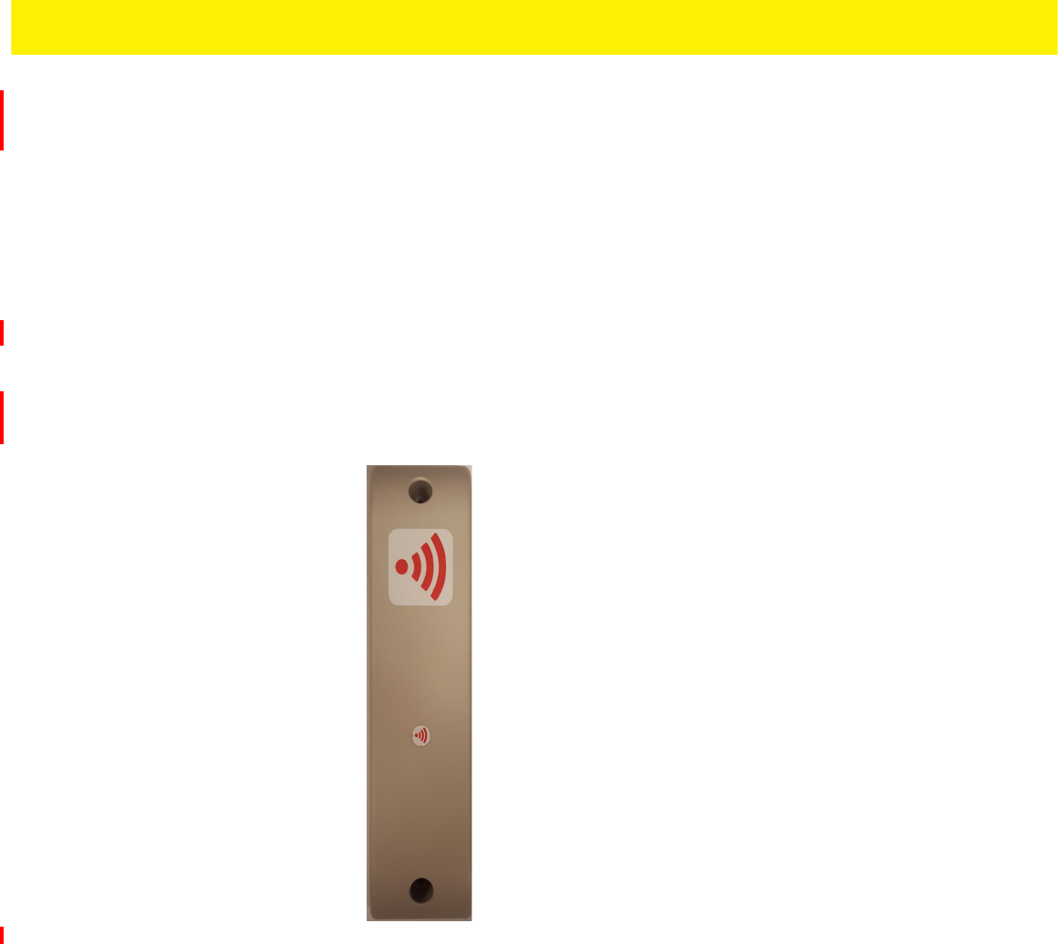
2.9 Beacon Part Number: GE-MB2001-01-WR
As a prerequisite, to mounting a GE-MB2001-01-WR model beacon, adhere to the following:
• Do not install the cover on the unit until the beacon has been initialized and configuration verified.
• Ensure the planned installation location matches your physical deployment plans.
• Beacon mounting heights may vary, but should be about 5' from the floor.
• Ensure the intended deployment location has WiFi coverage.
To mount a GE-MB2001-01-WR model beacon using the GE-MB2001-01-ACC:
1. Before peeling the cover off the GE-MB2001-01-ACC mounting system tape, hold the wall plate portion of the accessory in
its intended mounting location and mark the spot on the wall. You can use masking tape to mark the bottom of the unit.
2. Peel the tape from the adhesive pads on the rear of the beacon and press the to the wall.
3. Snap the beacon (GE-MB2001-01-WR) into the accessory wall plate.
Figure 2-22 GE-MB2001-01-WR Wall Mount
4. Place and snap the cover on the unit while ensuring logos are correctly oriented.
NOTE: If the surface is clean and smooth, use the 3M VHB tape to mount the beacon.
However, if wood, brink or other non-smooth surface is utilized, the 3M tape will not
adhere to the surface. Use appropriately sized screws for mounting (not included).
2 - 20 MPact Location & Analytics Hardware Installation Guide
Figure 2-23 GE-MB2001-01-WR Beacon Cover
Figure 2-24 GE-MB2001-01-WR Beacon Replacement Adhesive
NOTE: Once adhered to a surface, its very difficult to remove. The beacon’s adhesive
pads will need to be replaced if it is moved to a new location.

Beacon Hardware Specifications and Installation 2 - 21
Beacon Hardware Specifications and Installation 2 - 21
2.10 Initializing a GE-MB5000-01-WR Hub
A GE-MB5000-01-WR (or hub) scans for Bluetooth smart beacon emissions. The hub filters based on its scanning configuration
for known devices and forwards scan results to its defined administration (posting) server.
The hub ships with a default software load, but without its configuration. When the hub is initialized for the first time it
conducts an internal scan diagnostic but is unable to properly provision itself.
Consequently, the hub needs to be provisioned with both an initial configuration and a scanning configuration before it can
filter beacons and forward relevant scanning information.
To provide the hub its initial and scanning configurations:
1. Initialize the GE-MB5000-01-WR hub.
The hub scans for its initial configuration and displays a Wifi error stating the hub has not been configured.
The hub has a fixed SSID of mpact_init and a preset password of mpact123.
When unable to provision itself the hub connects to 192.168.100.1 (a fixed location) and downloads its initial configuration
file (badge_config.json).
The hub obtains its badge_config.json file and self-configures its initial configuration. Once completed, the hub connects
to its popsting server to obtain its scanning configuration.
The scanning configuration is required to define the hub’s scan interval and beacon profile determining how beacon data
is forwarded, based on the beacon’s UUID and Major values, and posted to the server for administration.
2. If you encounter issues with the setup of the hub, there’s several file restoration options available.
NOTE: The 192.168.100.1 location must be reachable from the hub’s connected Access
Point mpact_init SSID to receive its required badge_config.json file.
2 - 22 MPact Location & Analytics Hardware Installation Guide
Figure 2-25 GE-MB5001-01-WR
•Reboot the badge - Press and hold button 2 between 10 and 20 seconds, then release. LED 1 will blink slowly twice to
confirm. Any in-process configuration activity will need to be re-started.
•Erase to factory default configuration and reboot - Press and hold button 2 between 30 and 40 seconds, then release.
LED 1 will blink slowly twice to confirm. The deletion of the initial configuration could be warranted if the configuration
was not successfully applied on the first attempt. Once reverted to factory configuration, the initial config and scanning
config can be re-applied.
•Shutdown the badge - Press and hold button 2 between 20 and 30 seconds, then release. LEDs will blink 5 times to
confirm the badge shutdown. Use this process when brining a deployed badge offline.
Beacon Hardware Specifications and Installation 2 - 23
Beacon Hardware Specifications and Installation 2 - 23
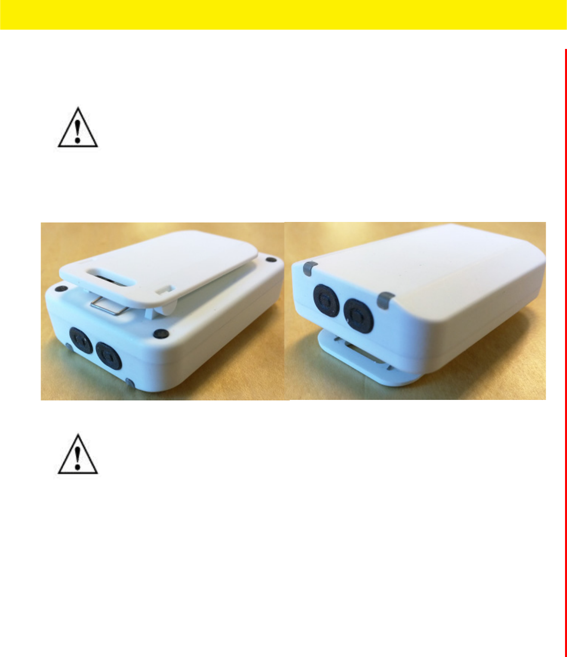
2.11 Beacon Part Number: GE-MB6000-01-WR Badge
A GE-MB6000-01-WR badge is a wearable beacon that’s clipped to one’s body, typcially in the mid section or belt area.
To mount a GE-MB6000-01-WR model badge:
1. Clip an initalized badge to your midsection or belt area
2. If you encounter issues with the setup of the badge, there’s several file restoration options available.
Figure 2-26 GE-MB6000-01-WR: LEDs and Buttons
•Reboot the badge - Press and hold button 2 between 10 and 20 seconds, then release. LED 1 will blink slowly twice to
confirm. Any in-process configuration activity will need to be re-started.
•Erase to factory default configuration and reboot - Press and hold button 2 between 30 and 40 seconds, then release.
LED 1 will blink slowly twice to confirm. The deletion of the initial configuration could be warranted if the configuration
was not successfully applied on the first attempt. Once reverted to factory configuration, the initial config and scanning
config can be re-applied.
•Shutdown the badge - Press and hold button 2 between 20 and 30 seconds, then release. LEDs will blink 5 times to
confirm the badge shutdown. Use this process when brining a deployed badge offline.
To replace a GE-MB6000-01-WR model badge clip:
1. TBD
2. TBD
NOTE: The clip portion of the badge is a replaceable part, GE-MB6000-01-ACC. Refer to
Part No. GE-MB6000-01-ACC when ordering a replacement clip to a GE-MB6000-01-WR
model badge.
NOTE: When the badge is facing you, the clip side facing you, button 1 is on the left top
and button 2 is on the top right.

2 - 24 MPact Location & Analytics Hardware Installation Guide
2.11.1 GE-MB6000-01-WR Battery Safety Precautions
2.11.1.1 When Using a GE-MB6000-01 Battery
Misusing the battery may cause the battery to get hot, rupture or ignite causing serious injury. Be sure to follow the safety rules
listed below:
• Do not place the battery in fire or heat the battery.
• Do not install the battery backwards so that the polarity is reversed.
• Do not connect the battery’s positive terminal and the negative terminal to each other with any metal object (such as a wire).
• Do not carry or store batteries together with necklaces, hairpins or other metal objects
• Do not pierce a battery with nails, strike the battery with a hammer, step on the battery or subject it strong impacts or
shocks.
• Do not apply solder to the battery
• Do not expose the battery to water or allow the battery to get wet or exposed to moisture.
• Do not disassemble or modify the battery. The battery contains safety and protection devices which, if damaged, may cause
the battery to generate heat, rupture or ignite.
• Do not place the battery on or near fires, stoves or other high temperature locations. Do not place the battery in direct
sunlight for prolonged periods. Do not store the battery in a car in hot weather, doing so may cause the battery to generate
heat, rupture or ignite.
• If the battery is to be used by small children, the caregivers should explain the contents of the user’s manual to the children.
The caregiver should provide adequate supervision to ensure the device is used as explained in the user’s manual.
• When the battery is worn out, insulate the terminals with adhesive tape or similar material before disposal.
• Immediately discontinue battery use if, while charging or storing, the battery emits an unusual smell, feels hot, changes
color, shape or appears abnormal in any other way.
• Do not place batteries in microwave ovens, high-pressure containers or induction cookware.
• In the event the battery leaks, and fluid gets into one’s eye, do not rub the eye. Rinse the eye with water and immediately
seek medical attention. If left untreated, the battery fluid could cause permanent damage to the eye.
2.11.1.2 While Charging a GE-MB6000-01 Battery
Be sure to follow the rules listed below when charging the battery. Failure to do so may cause the battery to become hot,
rupture, ignite and cause serious injury.
• When charging the battery, either use the specified battery charger or otherwise ensure the battery charging conditions
specified by the vendor are closely adhered to.
• Do not attach the battery to a power supply plug or directly to a car’s cigarette lighter.
• Do not place the battery in or near fire or in direct sunlight. When the battery becomes hot, its built-in safety measure are
activated, preventing the battery from charging. Heating the battery can destroy its safety equipment and result in an
overheat or ignition.
• Do not continue charging the battery if it does not charge within its specified charging time. Doing so may cause the battery
to become hot, rupture or ignite.
Beacon Hardware Specifications and Installation 2 - 25
Beacon Hardware Specifications and Installation 2 - 25
2.11.1.3 Discarding a GE-MB6000-01 Battery
Do not discharge the battery using and device except its designated device. When the battery is used in devices aside from its
designated device it may damage the performance of the battery and potentially reduce its useful expectancy. If the device
causes an abnormal current flow it may result in the battery becoming hot, rapture or ignite resulting in serious injury.
The temperature range through which the battery should be discharged is -20C - 60C. Discharging the battery outside of this
range may damage the battery’s performance or reduce its life expectancy.
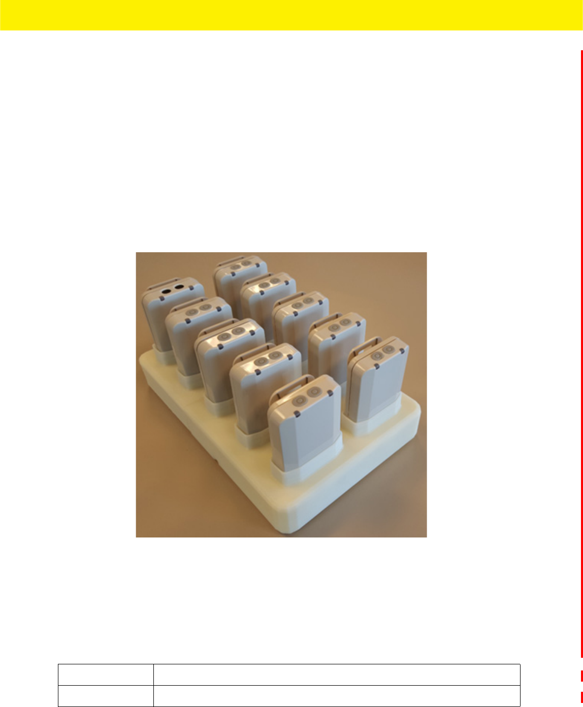
2.12 Cradle Charger: MPACT-MB6000-CHRGR
The badge cradle can charge one to ten badges at a time. The AC powered charger is a wall or desk mounted cradle platform
providing 5Vdc to each badge placed in individual charging slots. The charger feeds electric current through battery inside the
badge. The cell inside retains the energy passing through them.
Figure 2-27 MPACT-MB6000-CHRGR
Each slot has spring contacts that mate with the contacts on the badge. Badges have battery chargers and fuel gauges built
into each device so the charger is a power supply platform and no battery knowledge exists in the charger itself, everything to
charge and protect a lithium Ion battery is built into the badge itself.
The charger's primary function is providing 5Vdc at 900 mA to each badge holder re-charge badge batteries. The charger holds
badges when not in use. When badges are in the charger, they begin to charge using the 5Vdc supplied in the charger base. If
there is sufficient charge detected, the badge uses the charger as a holder (without charging).
While in the charger, the badge could conduct a software or configuration update if required and a status update.
Specification Value
Charger Capacity 1 - 10 badges simultaneously
2 - 26 MPact Location & Analytics Hardware Installation Guide
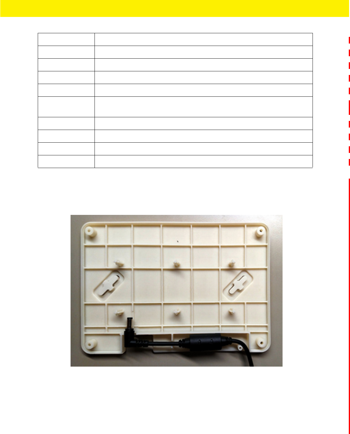
The charger is designed so a DC power cable can be installed from the rear of the charger housing without removing the base.
The cable and connector do not interfere with the base lying flat on any surface. The DC cord snakes through strain relief
features in the housing to prevent accidental disconnects. The external power adapter DC cable terminates with a right-angle
connector at the charger interface.
Figure 2-28 MPACT-MB6000-CHRGR - DC Power
2.12.1 Battery Charging Guidelines
Failure to follow these guidelines may result in fire, explosion or other hazard.
• The area in which the units are charged should be clear of debris and combustible materials or chemicals. Particular care
should be taken when charging in a non commercial environment.
• To charge the battery, the battery and charger temperatures must be between 0 - 40 degrees Celsius.
Voltage 5Vdc +/- 5%
Current Each Badge requires 900 mA during charging, total 5Vdc power is 10 Amps
Power Consumption 50-60 Watts
Power Supply External 12 Vdc, 5 Amps max, 60 watts total, enclosed power supply
Power Cord AC power cord connecting external power supply to AC power
Power Supply
Connector
Barrel connector (2.5mm outside diameter). The plastic enclosure has built-in strain relief
to prevent accidental disconnects.
Power Indicator All Badges within the charger platform have LEDs indicating charging state
Temperature 0 to 40 degrees C (operating), -40 to 70 degrees C (storage)
Humidity 5 to 95% RH (operating) 85% RH (storage)
Altitude 8,000 ft @ 28 degrees C (operating), 30,000 ft @ 12 degrees C (storage)

Beacon Hardware Specifications and Installation 2 - 27
Beacon Hardware Specifications and Installation 2 - 27
• Do not use incompatible batteries and chargers. Use of an incompatible battery or charger may present a risk of fire,
explosion, leakage or other hazard. If you have any questions about the compatibility of a battery or a charger, contact Zebra
Support.
• Do not disassemble, open, crush, bend or deform, puncture or shred the badge or charger
• Impact from dropping the badge and charger on a hard surface could cause the battery to overheat.
• Do not short circuit a battery or allow metallic or conductive objects to contact the battery terminals.
• Do not modify, remanufacture, insert foreign objects into the battery, immerse or expose to water or other liquids, or expose
to fire, explosion or other hazard.
• Do not leave or store the equipment in or near areas that might get very hot, such as in a parked vehicle or near a radiator
or other heat source. Do not place battery into a microwave oven or dryer
• If you suspect damage to your equipment or battery, contact Zebra Support to arrange for inspection.
2.12.2 Cleaning the Charging Cradle
The following materials are required to clean the charging cradle:
• Alcohol wipes
• Cotton tipped applicators
• Can of compressed air
Cleaning frequency is discretionary in respect to the environments the charger and the badges are deployed. They may be
cleaned as frequently as required.
2.12.2.1 Cleaning the Badge Contacts
To clean the contacts on a badge before inserting into the charging cradle:
1. Dip the cotton portion of the cotton tipped applicator in isopropyl alcohol.
2. Rub the cotton portion of the cotton tipped applicator back-and-forth across the contacts. Do not leave any cotton residue
on the contacts (repeat at least three times).
3. Use a dry cotton tipped applicator to clean any moisture or residue remaining on the contacts.
4. Spray compressed air on the contact area by pointing the nozzle about ½ inch away from the surface.
5. Inspect the area for any grease or dirt, repeat this process if required.
2.12.2.2 Cleaning the Cradle Connectors
To clean the connectors within the cradle:
1. Remove DC power cable from the cradle.
2. Dip the cotton portion of the cotton tipped applicator in isopropyl alcohol.
3. Rub the cotton portion of the applicator along the connector pins. Slowly move the applicator back-and-forth on the
connector to the other. Do not leave any cotton residue on the connector. All sides of the connector should also be rubbed
with the cotton tipped applicator.
4. Spray compressed air in the connector area by pointing the tube/nozzle about ½ inch away from the surface.
5. Ensure there is no lint left by the cotton tipped applicator, remove any lint if found.
6. If grease or other dirt can be found on other areas of the cradle, use a lint free cloth and alcohol to remove.

2 - 28 MPact Location & Analytics Hardware Installation Guide
7. Allow at least 10 to 30 minutes (depending on ambient temperature and humidity) for the alcohol to air dry before applying
power to cradle. If the temperature is low and the humidity is high, a longer drying time is required. Warm temperatures
and dry humidity require less drying time.
2.12.3 Troubleshooting
Refer to the following to troubleshoot issues with charging badges in the charger cradle:
Issue Solution
Cradle is not receiving power Ensure the power cable is connected securely to both the
cradle and its AC power source
The badge is not fully seated in the cradle Remove and re-insert the badge into the cradle, ensuring it is
correctly seated
The badge was placed in the cradle upside down Remove the badge from the cradle and re-insert in its proper
orientation
All badges are in the cradle correctly, the cradle is
plugged in, but none of the badges are charging
Unplug the cradle and plug back in again
Badge battery is faulty Verify other badges charge properly. If so, contact system
administrator.

If you have a problem with your equipment, contact Support for your region. Support and issue resolution is provided for
products under warranty or that are covered by a services agreement. Contact information and Web self-service is
available by visiting www.zebra.com/support.
When contacting Support, please provide the following information:
• MAC ID of the unit
• Model number or product name
• Software type and version number (if known)
Support responds to calls by email or telephone within the time limits set forth in support agreements. If you purchased
your product from a business partner, contact that business partner for support.
Customer Support Web Site
The support site, located at www.zebra.com/support provides information and online assistance including developer tools,
software downloads, product manuals, support contact information and online repair requests.
Manuals
To see manuals, go to:www.zebra.com/support.
NOTE: For GE-MB5000-01-WR, GE-MB6000-01-WR and GE-MB6000-CHRGR, the
customer will provide the serial number.
APPENDIX CUSTOMER SUPPORT

A - 2 MPact Location & Analytics Hardware Installation Guide

MN00XXXXA01 DRAFT July, 2016