Zebra Technologies P430I-MIFARE THERMAL CARD PRINTER User Manual P430i UM
Zebra Technologies Corporation THERMAL CARD PRINTER P430i UM
Contents
- 1. USERS MANUAL 1
- 2. USERS MANUAL 2
- 3. USERS MANUAL 3
USERS MANUAL 2
Installation and Setup
Unpacking the Printer
980470-001 Rev. A P430i User’s Manual 9
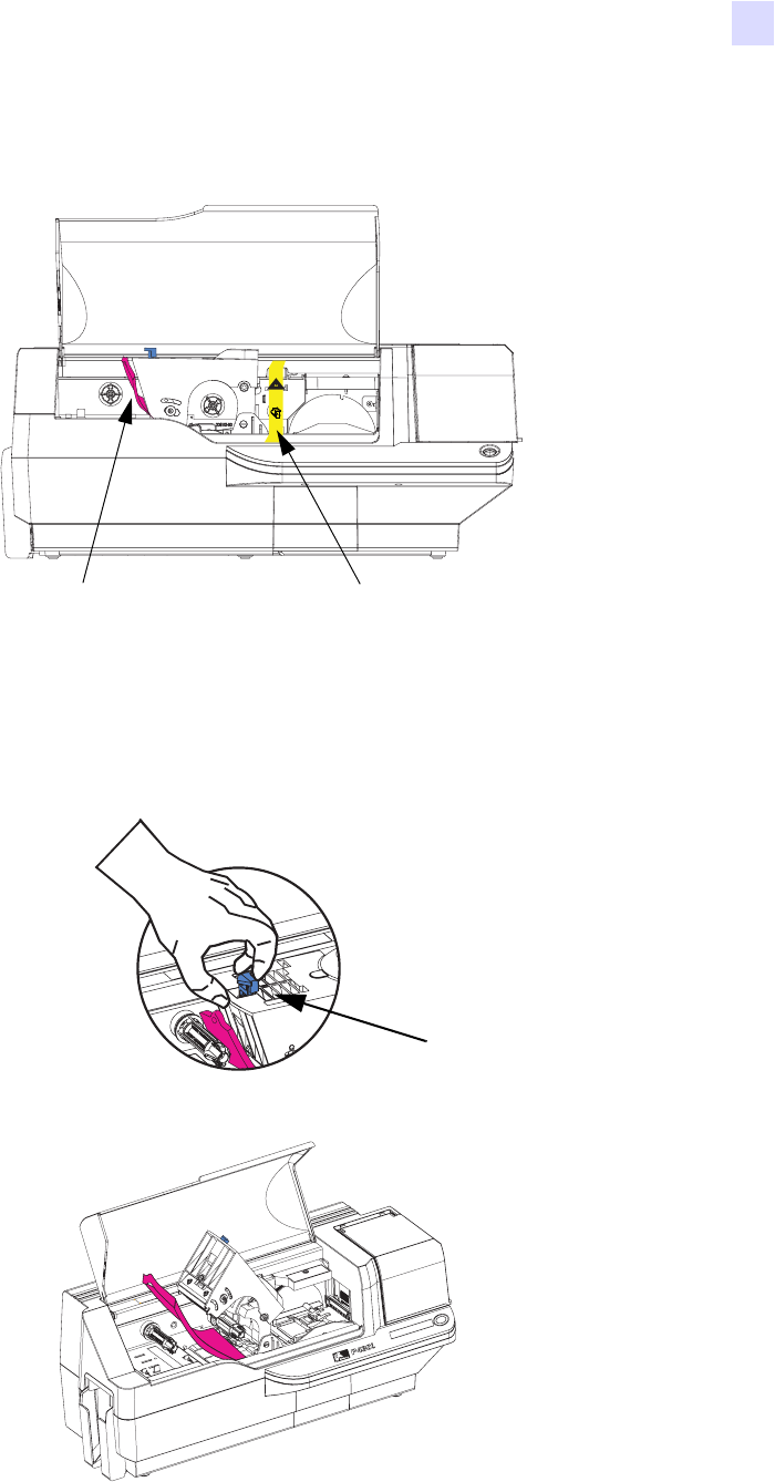
b. Locate the Print Head protection pad and the Card Cleaning Cartridge location tape (see below).
Remove the tape.
c. Release the Print Head Carriage by pushing the Print Head Carriage Latch to the left, and raise the Print
Head Carriage. It will remain open at about a 45° angle.
I
N
S
T
A
L
L
Remove me
Print Head P
rotection Pad
Card Cleaning Cartridge
Location Tape
Print Head
Carriage
Latch
Dual-Sided Color
10 P430i User’s Manual 980470-001 Rev. A
Installation and Setup
Installing the Print Driver Software and Setting Driver Options
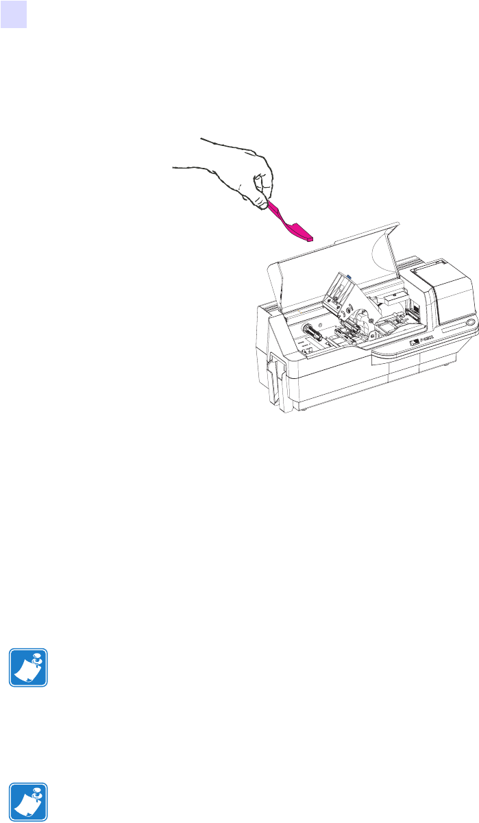
d. Remove the print head protection pad. Keep the pad, as well as the other packing material and the
shipping carton, in case the printer is shipped or moved. If the original material is lost, a replacement
Shipping Kit can be ordered from your reseller.
Installing the Print Driver Software and Setting Driver
Options
Printing with the P430i Printer requires the Windows Printer Driver and your card design/issuing software or
printer command level programming through the printer interface.
The P430i Card Printer can be used with any Windows 2000 or Windows XP computer, using the drivers
provided on CD with the printer.
This section contains information on the printing of a sample card in color (using the 5-panel color ribbon
YMCKO and the Windows Printer Driver).
Installing the P430i Print Driver
To install the P430i Printer Driver automatically on all Operating Systems, use the Zebra Install Wizard.
The Install Wizard will walk you through the appropriate installation steps. The Wizard will:
• Automatically launch when the driver CD is inserted.
• From the main menu of your documentation CD, select your desired language and then select “DRIVERS”
from the subsequent menu. The Install Wizard will walk you through the appropriate steps.
Note • If updating the printer driver from a previous version, before installing the updated
printer driver version, always delete the existing version from your computer.
Note • Ensure that you have administrative privileges to perform this installation, or contact
your IT department.
Dual-Sided Color
Installation and Setup
Loading a Ribbon
980470-001 Rev. A P430i User’s Manual 11
• Delete previous versions of the driver and clean up any necessary Registry entries. You must select
“Remove” from the install options to remove any previous driver versions.
Loading a Ribbon
i Series Printers require the use of i Series ribbons for full color printing. The Resin Thermal Transfer and Dye
Sublimination ribbons for P430i are specifically designed for your P430i Printer.
1. Place the printer power switch in the OFF (0) position.
2. If the printer’s Main Lid is closed:
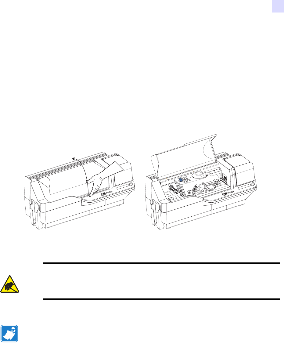
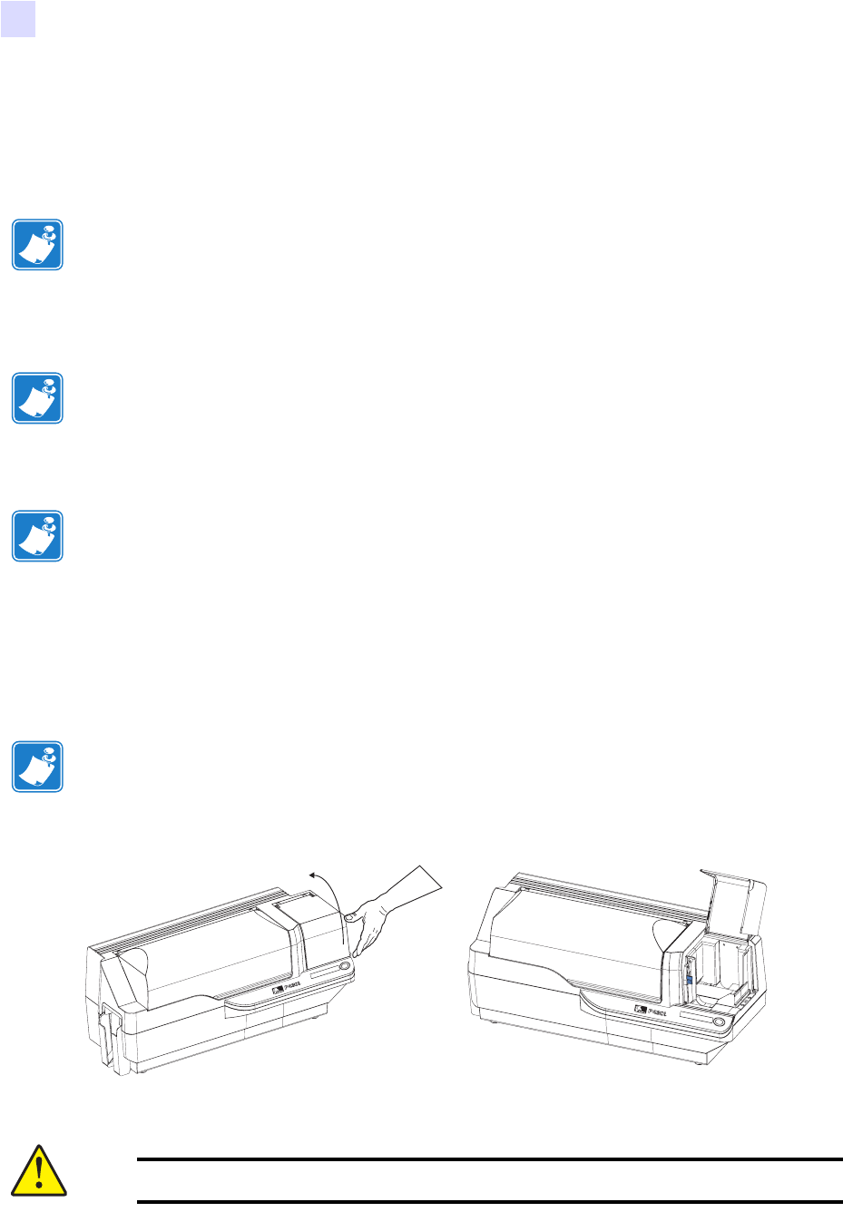
a. Open the printer’s Main Lid; lift it by the lip at the bottom front as shown in the figure below left.
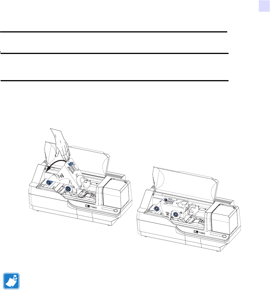
b. Raise the Print Head Carriage by pressing the release latch to the left (toward the output hopper) and
lifting as shown below to about a 45° angle. The Print Head Carriage will stay in that position, as
shown at the right below.
Electrostatic Discharge Caution • DO NOT TOUCH the Print Head or the electronic
components on the Print Head Carriage. Discharges of electro-static energy that
accumulate on the human body or other surfaces can damage the Print Head or other
electronic components used in the printer.
Note • Avoid any direct contact with the print head to prevent transfer of oils or
contamination. Outside of normal operation, only the Zebra-approved cleaning materials
should come in contact with the print head.
Dual-Sided Color
Dual-Sided Color
12 P430i User’s Manual 980470-001 Rev. A
Installation and Setup
Loading a Ribbon
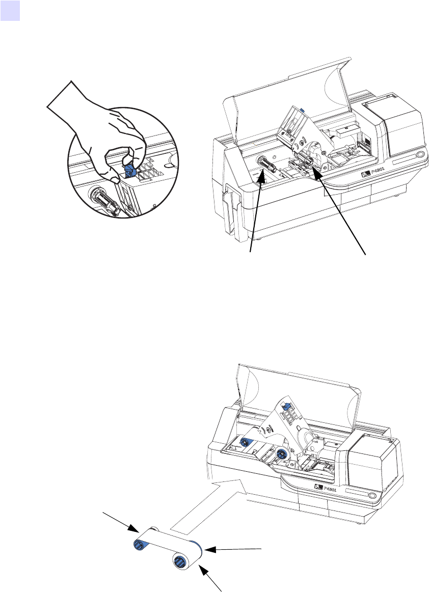
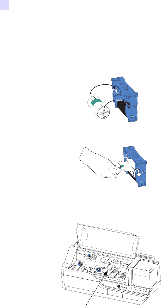
3. Locate the Ribbon Supply Spindle and the Ribbon Take-up Spindle (see above). Load ribbon onto the
supply spindle (under the print head carriage) flange side in, and load the empty core (with tape attached)
onto the take-up spindle. Make sure the ribbon comes off the top of the supply spindle and feeds to the top
of the take-up spindle.
Dual-Sided Color
Ribbon Supply
Spindle
Ribbon Take-up
Spindle
Dual-Sided Color
Flange
Supply Spool
Take-u p
Spool
Installation and Setup
Loading a Ribbon
980470-001 Rev. A P430i User’s Manual 13
4. Gently press the print head carriage down until it is fully lowered, as shown below. Very little force is
neccessary to perform this step.
Note • During normal operation (with power connected and turned on), the ribbon would
automatically synchronize when the Print Head is restored to its fully-down position. The
ribbon would be identified and the corresponding parameters sent to the driver.
Since power is not connected at this point in the Installation and Setup Procedure, nothing
will happen when the Print Head Carriage is closed. The ribbon will synchronize when
power is turned on.
Caution • Do not touch the print head if the printer has been in service within the last 10
minutes. It could be very hot and cause a burn.
Electrostatic Discharge Caution • A static discharge is possible if you touch any
exposed metal parts. Use of an anti-static wrist strap or comparable anti-static protection is
required.
Dual-Sided Color
Dual-Sided Color
14 P430i User’s Manual 980470-001 Rev. A
Installation and Setup
Installing the Card Cleaning Cartridge
Installing the Card Cleaning Cartridge
The Card Cleaning Cartridge cleans the cards entering the printer. The Card Cleaning Cartridge consists of a
Cartridge Frame and an Adhesive Roller, which are packed together.
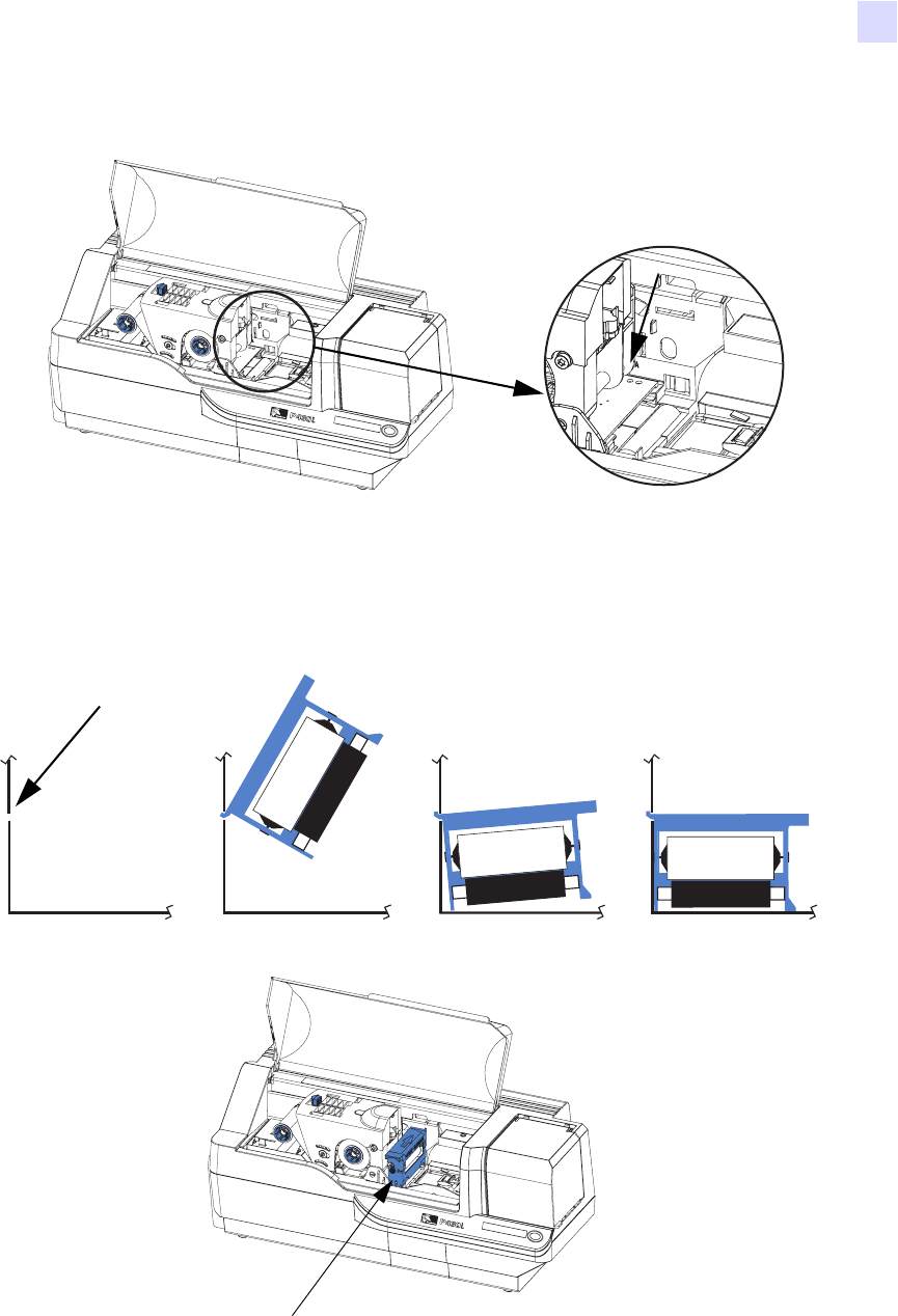
1. Remove the Cartridge Frame and the Adhesive Roller from their packaging. Insert the Adhesive Roller into
the Cartridge Frame, as shown below. To avoid contamination, always hold the frame and the roller by the
ends.
.
2. Peel the protective wrapper from the Adhesive Roller.
3. If the printer’s Main Lid is closed, open it. Locate the area where the Card Cleaning Cartridge will be
installed (initially, this area was covered by a warning tape).
Dual-Sided Color
Card Cleaning
Cartridge Mounting
Location
Installation and Setup
Installing the Card Cleaning Cartridge
980470-001 Rev. A P430i User’s Manual 15
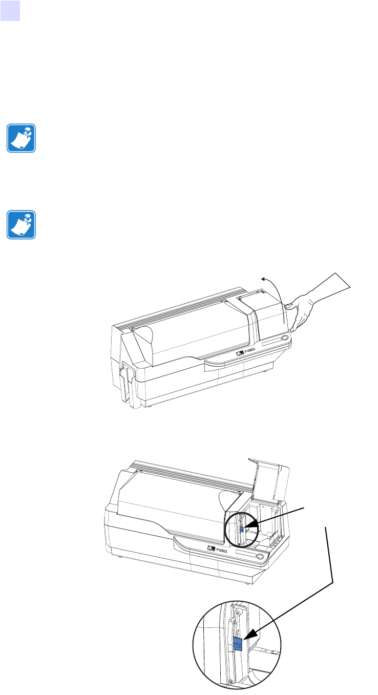
4. Locate the slot at the rear of the Card Cleaning Cartridge mounting location; see below.
5. Hold the Card Cleaning Cartridge by the extended “handle” (so the large arrow on the top is pointing away
from you). With the cartridge at about a 30° angle (pointing downward), insert the lip of the cartridge into
the slot, until the cartridge seats against the back wall. Then press the front of the cartridge down until it
seats all the way down and latches with an audible “click”. See below.
6. Close the printer’s Main Lid.
Dual-Sided Color
Card Cleaning
Slot
Card Cleaning Cartridge in final position
16 P430i User’s Manual 980470-001 Rev. A
Installation and Setup
Setting the Card Thickness Control
Setting the Card Thickness Control
The Card Thickness Control is set by the user to adjust the gap as cards enter the printer, to prevent
double-feeds (which could cause a jam) or mis-feeds.
1. Open the Card Feeder cover. The cover is hinged; lift it by the lip at the right front corner.
2. The Card Thickness Control Lever is at the front of the left-side opening of the Card Feeder area.
Note • Set the Card Thickness Control before loading cards.
Note • To reduce contamination and ensure better print quality, minimize the time the Card
Feeder cover is open.
Dual-Sided Color
Card Thickness
Control
Dual-Sided Color

Installation and Setup
Setting the Card Thickness Control
980470-001 Rev. A P430i User’s Manual 17
3. There are four detents to set the position of the Card Thickness Control. Slide the Card Thickness Control
to the position corresponding to the following:
Detent Position Card Thickness
Highest 50 mil (1.27 mm) to 60 mil (1.52 mm)
3rd position 30 mil (0.76 mm) to 50 mil (1.27 mm)
2nd position 20 mil (0.51 mm) to 40 mil (1.02 mm)
Lowest 10 mil (0.25 mm) to 20 mil (0.51 mm)
Note • The overlap in settings above accomodates variations in environmental conditions
(especially humidity) and cards from different manufacturers. In general, start at the lowest
position and move the lever up until cards feed reliably.
Note • “60 mil” (“1.524 mm”) cards may have a significant variation (over 10%) in the
actual thickness of the cards; do not use these cards unless each card has been measured to
have a thickness less than 66 mil (1.676 mm).
18 P430i User’s Manual 980470-001 Rev. A
Installation and Setup
Loading Cards
Loading Cards
This section shows how to load plastic cards into the P430i Printer. The P430i can use cards with a range of
thickness from 10 mil (0.25 mm) to 60 mil (1.5 mm).
The P430i Printer can also load and print cards fed individually. Information on this is given in the next chapter.
The plastic cards generally come in decks of 100 cards; the Card Feeder can hold a full deck of 100 30-mil
cards. Cards sometimes will stick together; this can cause mis-feeding or double-feeding. To avoid this, separate
the cards before loading, as described in steps 2 through 4 below.
1. If the Card Feeder cover is closed, open it. The cover is hinged; lift it by the lip at the right front corner.
Note • Do not mix cards of different thicknesses!
Note • DO NOT bend cards or touch print surfaces as this can reduce print quality. The
surface of the cards must remain clean and dust free. Always store cards in an enclosed
container. Ideally, use cards as soon as possible.
Note • For cards with magnetic stripe, refer to Appendix A for loading instructions.
Note • To reduce contamination and ensure better print quality, minimize the time the Card
Feeder cover is open.
Caution • Do not touch print surfaces of the cards; this can reduce print quality
Dual-Sided Color
Dual-Sided Color
Installation and Setup
Loading Cards
980470-001 Rev. A P430i User’s Manual 19
2. Remove all wrapping from the card deck.
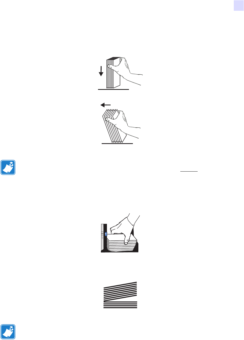
3. Holding the card deck by the sides, hold it vertically against a flat surface such as a desktop. If the deck is
too thick for your hand to hold it comfortably, use about half a deck at a time.
4. Push the stack back and forth to an angle of about 45° from vertical, so as to separate all of the cards.
5. Restore the card stack to its original squared-off condition, and place the cards in the input hopper.
6. Note that there will be a “gap” in the card stack, with several cards lying flat and the cards above angled
upward, as shown in the exaggerated drawing below. This is normal and ensures proper feeding.
Note • Static charges and edge burrs from the card die-cutting process can render individual
cards stuck together with significant adhesion force. These cards must be physically
separated from each other before inserting into the feeder; if not separated, feeding or
printing problems may occur.
Note • Do not try to eliminate the gap by pressing down on the card stack in the input
hopper; this can cause misfeeds.
20 P430i User’s Manual 980470-001 Rev. A
Installation and Setup
Card Output Hopper
Card Output Hopper
The card output hopper is normally extended to receive the printed cards. The printer may be operated with the
card output hopper in its closed position; in this case the cards will not be collected in the output hopper.
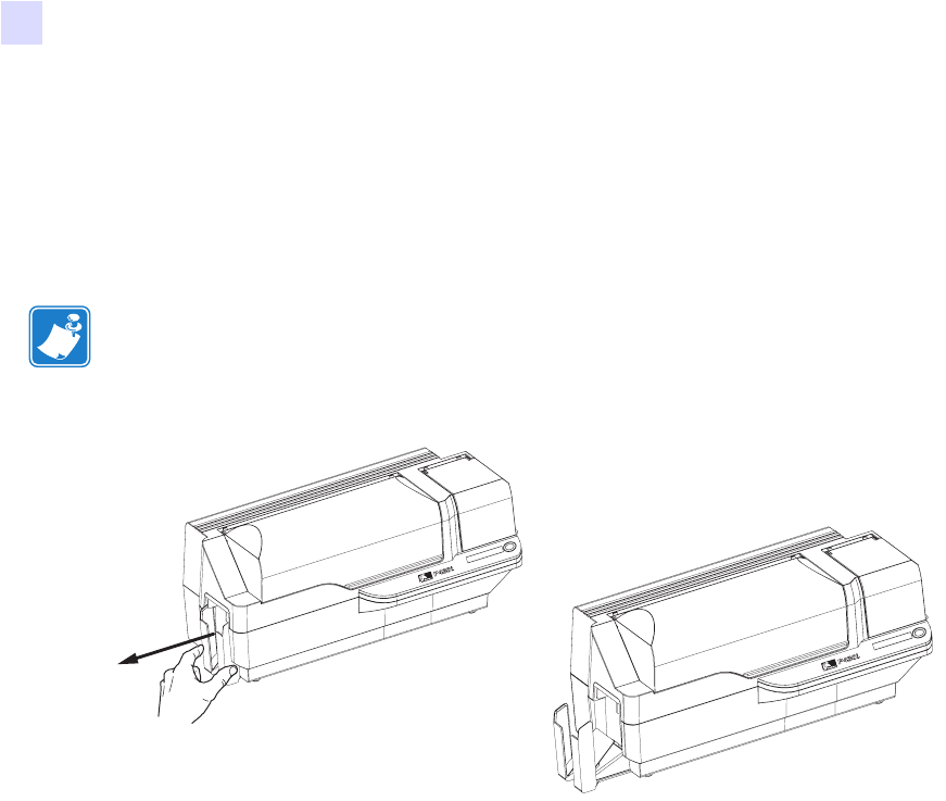
1. Pull the card output hopper out to place it in its functional position.
2. When not using the printer, slide the card output hopper back into its closed position to protect the printer
from dust and protect the output hopper from damage.
3. The output hopper can be completely removed from the printer if necessary by inserting a thin, blunt object
(such as a pencil) up through the hole in the bottom of the printer enclosure and pressing (up) to release the
hopper while simultaneously pulling the hopper out. To re-install the output hopper, simply slide the output
hopper in until it locks in place.
Note • The output hopper is a very snug fit to prevent it from moving during shipping or
operation; firm force is required to change its position.
Dual-Sided Color
Dual-Sided Color
Installation and Setup
Connecting the Printer to your Computer
980470-001 Rev. A P430i User’s Manual 21
Connecting the Printer to your Computer
The P430i Printer includes a standard USB interface.
As an option, the printer can be ordered with a 10/100base-T Ethernet Adapter (in addition to the USB
interface). The Ethernet Adapter can also be ordered as an add-on option and installed in the field by a Zebra
factory certified technician.
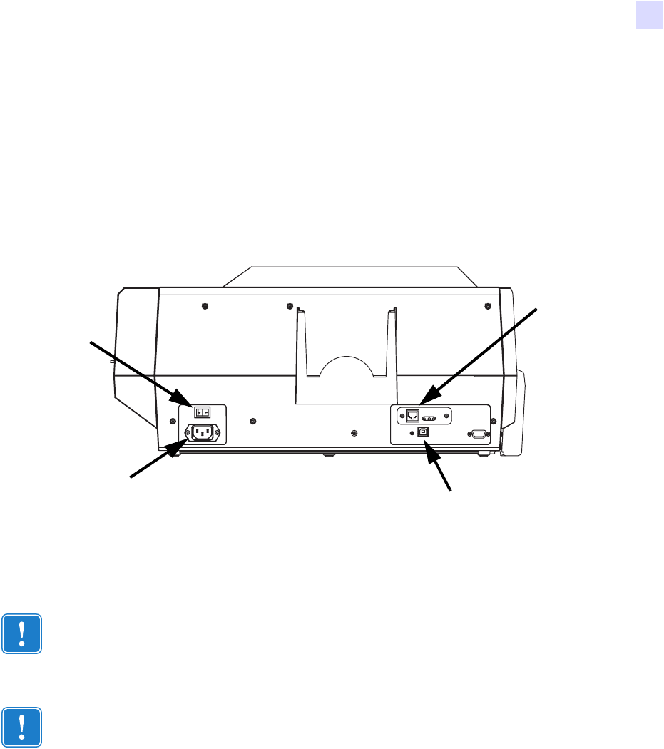
1. If using the USB interface, use the supplied USB cable to connect between the USB connector on the
printer and a USB port on the computer, as shown below. (Note that the figure below shows the optional
Ethernet Adapter directly above the USB Connector; this may not be present on your printer.)
2. If your printer includes the optional Ethernet Adapter as well as the standard USB connection, use either
the supplied USB cable or a standard Ethernet cable to connect the printer to a corresponding port on the
computer or network.
Important • Do not use both USB and Ethernet connections at the same time!
Important • Intermittent or unpredictable operation may occur from unsecured connectors.
If damaged, the power cable must be replaced by an exact equivalent.
USB Connector
Power
Connector
Power
Switch
(Optional)
Ethernet
Connector
22 P430i User’s Manual 980470-001 Rev. A
Installation and Setup
Connecting Power
Connecting Power
The P430i Printer includes an internal AC power supply that accepts nominal input voltage in the range from
110 to 230 volts at 50 to 60 Hertz. The power source must be grounded.
Depending on specific model number, your P430i Printer will include one or two power cords; use the one that
is appropriate for the AC power source connection at your location. If neither has an appropriate connector, AC
power cords may be purchased locally; make sure it is a three-wire (grounded) cord.
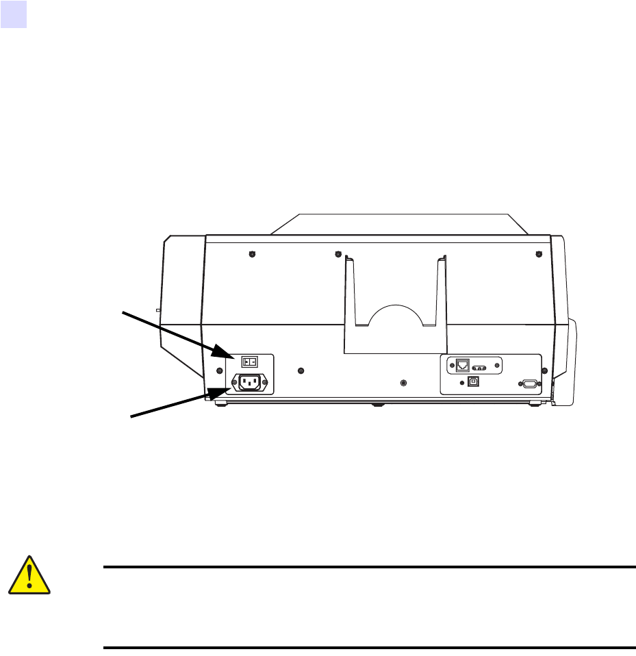
1. Place the Printer’s power switch in the OFF ( O ) position.
2. Depending on your local AC voltage, plug the appropriate power cord into the printer’s power connector
and a grounded AC power source connection.
3. To turn the Printer on, set the Printer’s power switch to the ON ( | ) position.
Caution • If the power cord appears damaged in any way, or if the power cord will not
securely plug into the Printer’s power connector or the AC power source connection,
STOP! Use of a damaged or incorrect power cord could cause equipment damage,
result in an electrical fire, or possibly cause injury.
Power
Connector
Power
Switch