Zebra Technologies R2844Z Thermal Printer with RFID User Manual Part 2
Zebra Technologies Corporation Thermal Printer with RFID Users Manual Part 2
UserManual.wiki
>
Zebra Technologies
>
R2844Z User Manual
>
Users Manual Part 2
Contents
1.
Users Manual
2.
Users Manual Part 2
3.
Users Manual Part 3
4.
Users Manual Part 4
5.
Users Manual Pt 1
6.
Users Manual Pt 2
7.
Users Manual Pt 3
8.
Users Manual Pt 4
Users Manual Part 2
Navigation menu
Upload a User Manual
Namespaces
Wiki Guide
HTML
PDF
Info
Views
User Manual
Discussion / Help
Navigation

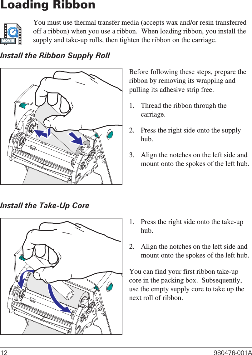
![Hooking Up the Printer and ComputerYour printer will have one of two combinations of interfaces:■Universal Serial Bus (USB), parallel and serial■USB, ethernet, and serialEach specific interface option—USB, parallel, ethernet, serial—is discussedindividually.You must supply the required interface cable for your application.CAUTIONS • Keep the power switch in the OFF position when attaching theinterface cable.The power supply barrel connector must be inserted into the power supplyreceptacle on the back of the printer before connecting or disconnecting thecommunications cables.This printer complies with FCC “Rules and Regulations,” Part 15, for Class BEquipment, using fully shielded six-foot data cables. Use of longer cables orunshielded cables may increase radiated emissions above the Class B limits.Interface Cable RequirementsData cables must be of fully shielded construction and fitted with metal ormetalized connector shells. Shielded cables and connectors are required toprevent radiation and reception of electrical noise.To minimize electrical noise pickup in the cable:Keep data cables as short as possible (6’ [1.83 m] recommended).Do not tightly bundle the data cables with power cords.Do not tie the data cables to power wire conduits.USB Interface RequirementsUniversal Serial Bus (version 1.1) provides a high-speed interface that iscompatible with your existing PC hardware. USB’s “plug and play” designmakes installation easy. Multiple printers can share a single USB port/hub.16 980476-001AMOVIE](https://usermanual.wiki/Zebra-Technologies/R2844Z.Users-Manual-Part-2/User-Guide-416250-Page-10.png)