Zebra Technologies R2844Z Thermal Printer with RFID User Manual Pt 4
Zebra Technologies Corporation Thermal Printer with RFID Users Manual Pt 4
Contents
Users Manual Pt 4
52 980476-001A
Maintenance
Cleaning
When you clean the printer, use one or more of the following supplies that
best suits your needs:
CLEANING SUPPLIES
Cleaning pens (12)
Cleaning swabs (25)
Cleaning cards, 4-in wide (25)
Save-a-Print Head film, 4-in wide (3)
The cleaning process takes just a couple of minutes using the steps outlined
below.
Printer Part Method Interval
Print head
Let the print head to cool for one minute, then use a new
cleaning pen to swab the print elements (the thin gray
line on the print head) from end to end. NOTE: You do
not have to turn off the printer to do this.
If print quality remains poor after cleaning, try the
Save-a-Print Head cleaning film to remove buildup
without damaging the print head. Call your authorized
reseller for more information.
As
necessary
or after
every five
rolls of
media
Platen roller
Manually rotate the platen roller. Clean it thoroughly
with 70% isopropyl alcohol and a cleaning swab,
cleaning card, or lint-free cloth.
Peel bar Clean it thoroughly with 70% isopropyl alcohol and a
cotton swab.
As needed
Tear bar
Exterior Water-dampened cloth
Interior Brush or air blow
Cutter Use tweezers to remove scraps
980476-001A 53

Adhesives and coatings of media can over time transfer onto the printer
components along the media path including the platen and print head.
This build-up can accumulate dust and debris. Failure to clean the print
head, media path and platen roller could result in inadvertent loss of labels,
label jams and possible damage to the printer.
Print Head Considerations
Always use a new cleaning pen on the print head (an old pen carries
contaminants from its previous uses that may damage the print head).
Media Path Considerations
Use a cleaning swab or pen to remove debris, dust or crust that has built-up
on the holders, guides and media path surfaces.
1. Use the alcohol in the cleaning swab or pen to soak the debris so that it
breaks up.
2. Wipe the area with the cleaning swab or pen to remove the debris.
3. Discard the cleaning swab or pen after use.
Cleaning Card Considerations
Use a cleaning card to remove debris that has built-up on the platen. Avoid
scrubbing or vigorously rubbing the platen; otherwise, the surface could be
damaged.
1. Open the printer and remove labels.
2. Place the cleaning card into the label path so that it is under the guides
and it extends between the print head and platen roller.
3. Close and latch the printer.
4. With the power switch on, press the feed switch to move the cleaning
card through the printer.
5. Discard the card after use.
54 980476-001A
MOVIE

Platen Considerations
The standard platen (drive roller) normally does not require cleaning. Paper
and liner dust can accumulate without effecting print operations.
Contaminates on the platen roller can damage the print head or cause the
media to slip when printing. Adhesive, dirt, general dust, oils and other
contaminates should be cleaned immediately off the platen.
Keep a new platen available as a spare and install it whenever the printer
has significantly poorer performance, print quality or media handling. If
sticking or jamming continues even after cleaning, you must replace the
platen.
The platen can be cleaned with a fiber-free swab (such as a Texpad swab)
or a lint free, clean, damp cloth very lightly moistened with medical grade
alcohol (70% pure or better).
1. Open the media door and remove the media.
2. Clean the platen surface with the alcohol moistened swab. Rotate the
platen while swabbing. Repeat this process two to three times with a
new swab to remove residual contaminates. Adhesives and oils, for
example, may be thinned by the initial cleaning but not completely
removed.
3. Discard the cleaning swab or pen after use.
Allow the printer to dry for one minute before loading labels.
Lubrication
No lubricating agents of any kind should be used on this printer! Some
commercially available lubricants, if used, will damage the finish and the
mechanical parts inside the printer.
980476-001A 55
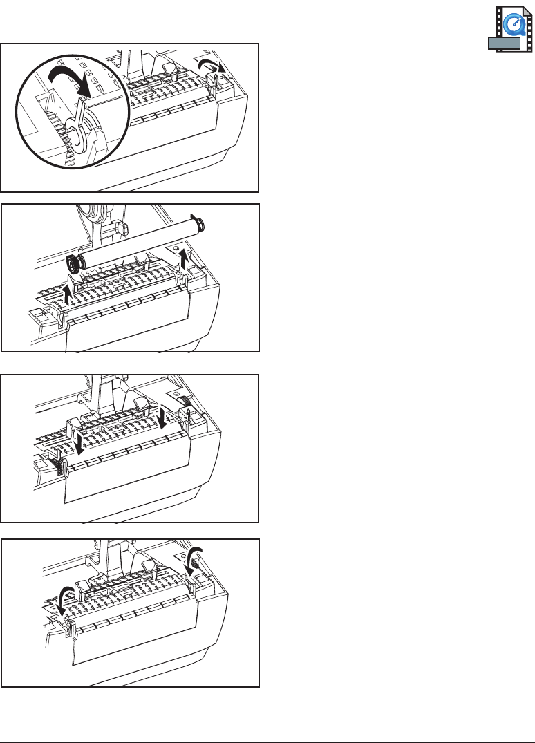
Replacing the Platen
Removal
Open the printer and remove any media.
1. Using a pointed stylus (such as
tweezers, small slot-head screwdriver,
or razor-knife), unhook the tabs on the
right and left sides. Then rotate them
forward.
2. Lift the platen out of the printer’s
bottom frame.
Assembly
Make sure the right bearing is on the shaft
of the platen.
1. Align the platen with the gear to the
left and lower it into the printer’s
bottom frame.
2. Rotate the tabs back and snap them
into place.
56 980476-001A
MOVIE

Replacing the Print Head
In the event you need to replace the print head, read the procedure and
review the removal and installation steps before actually replacing the print
head.
Prepare your work area by protecting against static discharge. Your work
area must be static-safe and include a properly grounded conductive
cushioned mat to hold the printer and a conductive wrist strap for yourself.
CAUTION • Turn the printer power off and unplug the power cord before replacing
the print head.
980476-001A 57
MOVIE
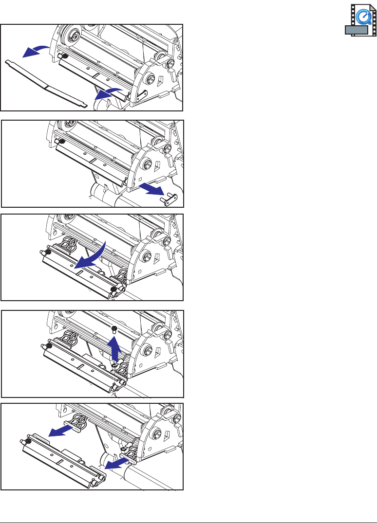
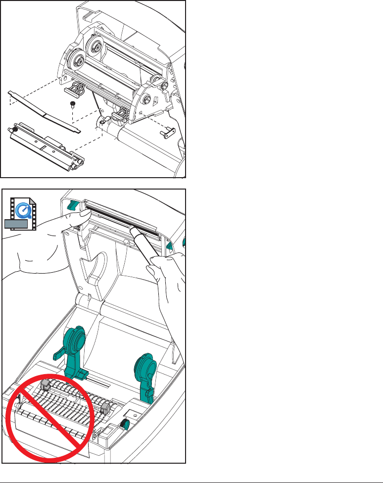
Thermal-Transfer TLP Model
Before following the steps in this
procedure, open the printer by
pulling the release latches forward then
lifting the top cover. Remove any ribbon
from the carriage.
Removal
1. Grasp the print head spring and pull it
to the left; then, slide it free of the
carriage.
2. Use the spring to pry the print head
clip off the right side of the carriage.
3. Pull the print head and bracket
forward.
4. Use a #2 Phillips driver to remove the
screw that holds the ground wire.
5. Unplug both bundles of print head
wires from their connectors.
58 980476-001A
MOVIE
Replacing the TLP Print Head (Continued)
Assembly
The new print head comes with the clip
and ground screw attached.
1. Align the print head and bracket to
plug the left and right connectors into
the black and white wire bundles.
2. Attach the ground wire and secure it
with the screw. Use a #2 Phillips
driver to tighten it.
3. Insert the bracket pegs into the left
side of the carriage.
4. Align the right side of the bracket and
insert the print head clip through the
right side of the ribbon carriage into
the bracket.
5. Slip the left end of the print head
spring into the left side of the ribbon
carriage; then slide the right end into
the other side. The angle of the “V”
fits into the indent on top of the print
head bracket.
6. Clean the print head with the cleaning
pen.
Reload media and ribbon. Plug in the
power cord. Print a status report to ensure
proper function.
980476-001A 59
MOVIE
60 980476-001A
Troubleshooting
Resolutions
1. The printer is not receiving power.
■Have you turned on the printer power?
■Check power connections from the wall outlet to the power supply, and
from the power supply to the printer.
2. The printer is on and in an idle state.
■No action necessary.
980476-001A 61
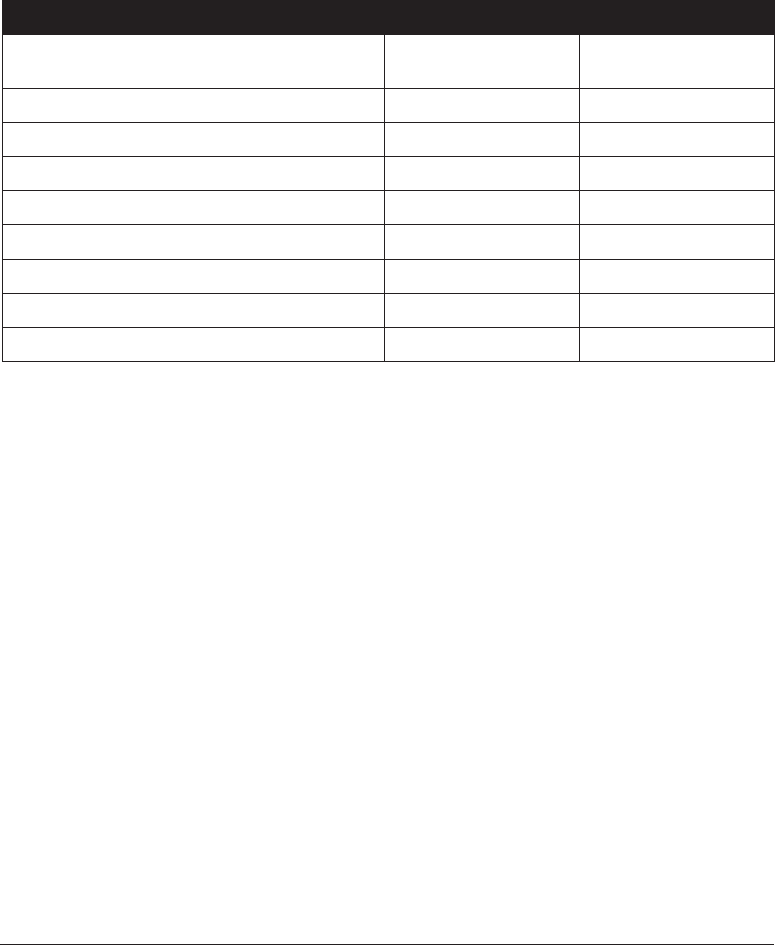
What the Status Light is Telling You
Status LED
Condition and Color
Printer
Status
For a Resolution,
Refer to number:
Off Off 1
Solid Green On 2
Flashing Yellow Stopped 3
Flashing Green Normal Operation 4
Flashing Red Stopped 5
Double Flashing Green Paused 6
Solid Yellow Various 7
Alternately Flashing Green and Red Needs Service 8

3. The printer has failed its power on self test (POST).
■If this error occurs right after you turn on the printer, contact an
authorized reseller for assistance.
There is a shortage of memory.
■If this error occurs after you have been printing, turn the printer power
off and on. Then, resume printing.
4. The printer is receiving data.
■As soon as all of the data has been received, the status LED will turn
green; then, the printer will automatically resume operation.
5. Either the media or ribbon is out.
■Load a roll of media, following the instructions in “Loading the Media”
on page 9. Then, press the feed button to resume printing.
■Load a roll of ribbon, following the instructions in “Loading the
Ribbon” on page 12. Then, press the feed button to resume printing.
The print head is open.
■Close the top cover. Then, press the feed button to resume printing.
6. The printer is paused.
■Press the feed button to resume printing.
62 980476-001A

7. The print head is under temperature.
■Continue printing while the print head reaches the correct operating
temperature.
The print head is over temperature.
■Printing will stop until the print head cools to an acceptable printing
temperature. When it does, the printer will automatically resume
operation.
8. FLASH memory is not programmed.
■Return the printer to an authorized reseller.
980476-001A 63

Print Quality Problems
No print on the label.
■You must use the correct media for the method of printing you require.
When printing without a ribbon, you must use direct thermal media.
When using ribbon, you must use thermal transfer media. The printer's
ribbon sensor detects motion of the supply spindle.
■Is the media loaded correctly? Follow the instructions in “Loading the
Media” on page 9.
The printed image does not look right.
■The print head is dirty. Clean the print head according to the
instructions on page 59.
■The print head is under temperature.
■Adjust the print darkness and/or print speed. Refer to the six-flash
sequence in “Feed Button Modes” on page 70, or the
^PR
and
~SD
commands in the ZPL II Programming Guide.
■The media being used is incompatible with the printer. Be sure to use
the recommended media for your application, and always use
Zebra-approved labels and tags.
There are long tracks of missing print (blank vertical lines) on
several labels.
■The print head is dirty. Clean the print head as shown on page 59.
■The print head elements are damaged. Replace the print head (see
“Replacing the Print Head” on page 58).
The ribbon sensor settings did not print.
■The printer is set for direct thermal printing; use the
^XA^MTT^XZ
command to reset the printer for thermal transfer printing and calibrate
again.
64 980476-001A

The printing does not start at the top of the label, or misprinting of
one to three labels.
■The media may not be threaded under the media guides. Refer to
“Loading the Media” on page 9.
■The printer needs to be calibrated. Refer to “Auto Calibration” on page
14.
■The correct media sensor may not be activated. Manual calibration
selects the media sensing method for the labels being used (refer to the
^MN
command in the ZPL II Programming Guide).
■Verify that the Label Top (
^LT
) command is correctly set for your
application (consult the ZPL II Programming Guide).
A label format was sent to, but not recognized by, the printer.
■Is the printer in pause mode? If so, press the feed button.
■If the status LED is on or flashing, refer to “What the Status LED is
Telling You” on page 61.
■Make sure the data cable is correctly installed.
■A communications problem has occurred. First, make sure that the
correct communications port on the computer is selected. Refer to
“Communicating with the Printer” on page 18.
980476-001A 65

RFID Symptoms
External reader cannot confirm RFID tags are programmed.
■Is the printer set up correctly? Print a configuration label to verify RFID
version. See “Auto Calibration” on page 14.
■Check if supported RFID media is loaded correctly.
VOID messages are printed across media.
■Verify tag type is properly selected in ZPL II. Use RFID media with
supported tag type. Edit ZPL II to select proper tag type or increase
retries.
■ZPL II is attempting to write to a non-existent block. Some tags’ blocks
are identified as 0-7. If ZPL II attempts to write to block “8,” it will fail.
■Check voided tag on external reader. If this is a media probelm, discard
or return bad tags.
■Media's transponder is out of range from printer's antenna. Contact
Zebra for the latest media and transponder specifications.
Nothing is printed.
■See if the correct media is loaded or load new, fresh media.
■See if tags can be read/programmed using other hardware.
■Verify ZPL II RFID commands. Debug the printing program.
■Tag is out of reach of the antenna or too close. Verify tag alignment.
■Wrong type of tag was selected. Check ZPL II.
■Block is write protected. Ensure that the tag is not write protected.
■Aluminum and other metals within tag may interfere with read/write.
Make sure media meets requirements.
■Increase the number of retries in the ZPL II commands.
■Time out may have occurred during internal communication. Cycle
power and try printing label again.
Call a service technician if you have been unsuccessful in getting your
expected print out and data.
66 980476-001A
Manual Calibration
Manual calibration is recommended whenever you are using pre-printed
labels (or label backing) or if the printer will not correctly auto calibrate.
1. Turn on the printer power.
2. Remove approximately 4" (102 mm) of labels from a section of backing
material. Load the media so that only the backing material is threaded
through the printer and under the print head.
3. Press and hold the feed button until the green status LED flashes once,
then twice. Release the feed button.
4. The printer will set the media sensor for the label backing being used.
After it is done making this adjustment, the roll will automatically feed
until a label is positioned at the print head.
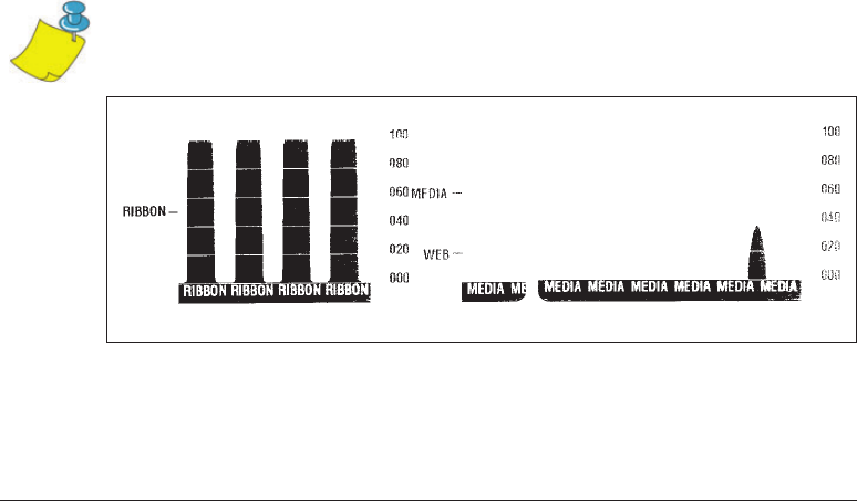
5. A profile of the media sensor settings (similar to the example below)
will print. Upon completion, the printer will save the new settings in
memory and the printer is ready for normal operation.
6. Press the feed button. One entire blank label will feed. If this does not
happen, try defaulting (refer to the four-flash sequence in “Feed Button
Modes” on page 70) and recalibrating the printer.
NOTE • Performing a manual calibration disables the auto calibration function. To
return to auto calibration, default the printer (see the four-flash sequence in “Feed
Button Modes” on page 70).
980476-001A 67
Troubleshooting Tests
Printing a Configuration Label
To print out a listing of the printer’s current configuration, refer to the
one-flash sequence in “Feed Button Modes” on page 70.
Recalibration
Recalibrate the printer if it starts to display unusual symptoms, such as
skipping labels. See “Auto Calibration” on page 14.
68 980476-001A
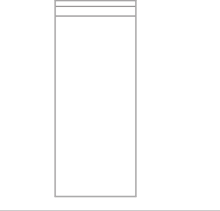
+10 DARKNESS
+000 TEAR OFF
TEAR OFF PRINT MODE
NON-CONTINUOUS MEDIA TYPE
WEB SENSOR TYPE
THERMAL-TRANS. PRINT METHOD
104 0/8 MM PRINT WIDTH
12 LABEL LENGTH
.0IN MM MAXIMUM LENGTH
0 BAUD
8 BITS DATA BITS
NONE PARITY
XON/XOFF HOST HANDSHAKE
NONE PROTOCOL
000 NETWORK ID
NORMAL MODE COMMUNICATIONS
<˜> 7EH CONTROL PREFIX
<^> 5EH FORMAT PREFIX
<,> 2CH DELIMITER CHAR
ZPL II ZPL MODE
MEDIA POWER UP
FEED HEAD CLOSE
DEFAULT BACKFEED
+020 LABEL TOP
+0000 LEFT POSITION
029 WEB S.
068 MEDIA S.
050 RIBBON S.
050 MARK S.
001 MARK MED S.
CS MODES ENABLED
.. MODES DISABLED
832 8/MM FULL RESOLUTION
SP.814.B <- FIRMWARE
V2.2.6.98.C HARDWARE ID
CUSTOMIZED CONFIGURATION
1024.............R: RAM
0768.............E: ONBOARD FLASH
NONE FORMAT CONVERT
NONE OPTION
NONE ZEBRA NET II
400:Ver. 2. RFID VERSION
................
...............
...........
.....
................
.....
.........
48...............
39 988 .....
NOT CONNECTED ...... USM COMM.
PARALLEL........... PARALLEL COMM.
RS232 ............. SERIAL COMM.
860 ...............
.............
...............
...........
...............
................
........
...........
...........
...........
.............
FEED...............
...............
............
...............
..............
................
................
................
................
................
062................ MEDIA LED
000................ RIBBON LED
081................ MARK LED
.................
.................
......
.....
........
.........
...............
................... TWINAX/COAX ID
...............
...............
OEM 4F
Zebra Technologies
ZTC R2844-Z-200dpi
PRINTER CONFIGURATION
FIRMWARE IN THIS PRINTER IS COPYRIGHTED
Resetting the Factory Default Values
Sometimes, resetting the printer to the factory defaults solves some of the
problems. Follow the four-flash sequence instructions in “Feed Button
Modes” on page 70.
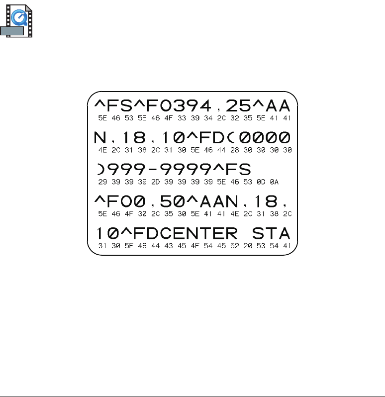
Communications Diagnostics
If there is a problem transferring data between the computer and printer, try
putting the printer in the communications diagnostics mode. The printer
will print the ASCII characters and their respective hexadecimal values (a
sample is shown below) for any data received from the host computer. To
find out how, refer to the power off mode procedure in “Feed Button
Modes” on page 70.
980476-001A 69
MOVIE
Feed Button Modes
Power Off Mode (Communications Diagnostics Mode)
With the printer power off, press and hold the feed button while you turn on the power. The printer
prints out a listing of its current configuration (see Figure 22). After printing the label, the printer will
automatically enter a diagnostic mode in which the printer prints out a literal representation (see Figure
23) of all data subsequently received. To exit the diagnostic mode and resume printing, turn off and then
turn on the printer.
Power On Modes
With the printer power on and top cover closed, press and hold the feed button for several seconds. The
green status LED will flash a number of times in sequence. The explanation at the right (Action) shows
what happens when you release the key after the specific number of flashes.
Flash
Sequence Action
*A configuration label prints.
*
**
The media sensor calibrates and a media sensor profile prints (see “Manual
Calibration” on page 67).
*
**
***
To reset the communication parameters. Press and release the feed button while
the LED rapidly flashes yellow and green.
For autobaud synchronization: Send a ZPL II format to the printer while the LED
rapidly flashes yellow and green. When the printer and host are synchronized, the
LED changes to solid green. NOTE: No labels will print during autobaud
synchronization.
*
**
***
****
Resets the factory defaults, auto calibrates, and saves settings into memory.
*
**
***
****
*****
The print width calibrates. While the status LED alternately flashes green and
yellow, a series of stacking rectangles print on the label. When the rectangle prints
to the outer edges of the label, press and release the feed button. The label width
and current communication parameters will be saved into memory.
*
**
***
****
*****
******
The print darkness calibrates. A series of nine samples print, starting with the
lightest and ending with the darkest image. When the desired print darkness is
achieved, press and release the feed button. The print darkness will be saved into
memory.
If the feed button remains pressed after a 7-flash sequence, the printer will ignore the button
when it is released.
70 980476-001A
MOVIE
MOVIE
MOVIE
MOVIE
MOVIE
MOVIE
MOVIE

Appendix
Interfaces
Universal Serial Bus (USB) Connector
The figure below displays the cable wiring required to use the printer’s
USB interface.
For printer supported operating systems and drivers, see the software and
documentation CD or visit the Zebra printer web site at:
http://www.zebra.com
For information on the USB interface, go to the USB web site at:
http://www.usb.org
980476-001A 71
Pin Signal
1 Vbus-N/C
2D-
3D+
4 Ground
Shell Shield/
Drain Wire
1
2
34

Parallel Interface Technical Information
The maximum current available through the interface port is not to exceed a
total of 0.75 amps.
Pin No. Description
1 NStrobe/Host Clk
2-9 Data Bits 1-8
10 nACK/PtrClk
11 Busy/Per Busy
12 PError/ACK Dat Req.
13 Select/Xflag
14 NAuto Fd/Host Busy
15 Not Used
16-17 Ground
18 +5 V @ 0.75 A Fused
19-30 Ground
31 nInit
32 NFault/nData Avail.
33-34 Not Used
35 +5 V throught 1.8 K Ohms Resistor
36 NSelectin/1284 active
72 980476-001A
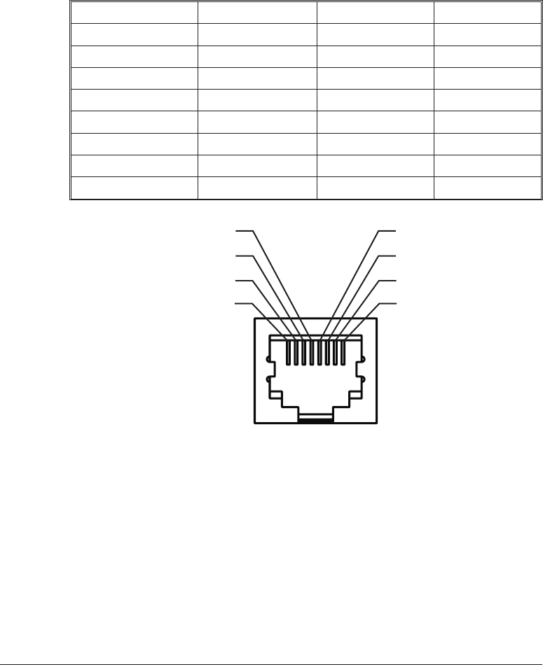
ZebraNet® PrintServer II for Ethernet Networks
This interface uses an RJ-45 straight-through cable type. The table below
provides the pinout assignments.
Signal Pin Pin Signal
Tx+ 1 1 Tx+
Tx- 2 2 Tx-
Rx+ 3 3 Rx+
--- 4 4 ---
--- 5 5 ---
Rx- 6 6 Rx-
--- 7 7 ---
--- 8 8 ---
You can refer to the ZebraNet® PrintServer IITM for Ethernet Networks
Installation and Operation Guide for details regarding this interface.
980476-001A 73
Pin 4
Pin 3
Pin 2
Pin 1
Pin 5
Pin 6
Pin 7
Pin 8
Looking into the Printer’s
RJ-45 Modular Connector

Serial (RS-232) Connector
Pin No. Description
1 Not used
2 RXD (receive data) input to the printer
3 TXD (transmit data) output from the printer
4DTR (data terminal ready) output from the printer -- controls when the
host may send data
5 Chassis ground
6 DSR (data set ready) input to the printer
7RTS (request to send) output from the printer -- always in the ACTIVE
condition when the printer is turned on
8 Not Used
9 +5 V @ 0.75 A fused
The maximum current available through the serial and/or parallel port is not
to exceed a total of 0.75 Amps.
When XON/XOFF handshaking is selected, data flow is controlled by the
ASCII control codes DC1 (XON) and DC3 (XOFF). The DTR control lead
will have no effect.
Interconnecting to DTE Devices —The printer is configured as data
terminal equipment (DTE). To connect the printer to other DTE devices
(such as the serial port of a personal computer), use an RS-232 null modem
(crossover) cable.
Interconnecting to DCE Devices —When the printer is connected via its
RS-232 interface to data communication equipment (DCE) such as a
modem, a STANDARD RS-232 (straight-through) interface cable must be
used.
74 980476-001A
980476-001A 75
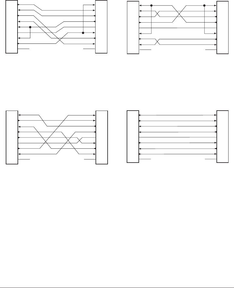
Connecting the Printer to a DTE Device
DB-25S
Connector
to DTE Device (PC)
DB-9S
Connector
to DTE Device (PC)
DB-9P
Connector
to Printer
DB-9P
Connector
to Printer
2
3
4
5
6
7
8
20
22
1
2
3
4
5
6
7
8
9
TXD
TXD
RXD RXD
RTS
RTS
CTS
CTS
DSR
DSR
GND
GND
DCD
DCD
DTR
DTR
1
2
3
4
5
6
7
8
9
1
2
3
4
5
6
7
8
9
TXDTXD
RXDRXD
RTS
RTS
CTS
CTS
DSRDSR
GNDGND
DCD
DCD
DTRDTR
Connecting the Printer to a DCE Device
DB-25S
Connector
to DCE Device
DB-9S
Connector
to DCE Device
DB-9P
Connector
to Printer
DB-9P
Connector
to Printer
2
3
4
5
6
7
8
20
22
1
2
3
4
5
6
7
8
9
1
2
3
4
5
6
7
8
9
1
2
3
4
5
6
7
8
9
TXD
TXD TXD
TXD
RXD
RXD RXD
RXD
RTS
RTS
CTS
CTS
CTS
CTS
RTS
RTS
DSR
DSR
DTR
DTR
GND
GND GNDGND
DCD
DCD DCD
DCD
DTR
DTR
DSR
DSR

76 980476-001A