Zebra Technologies RFID-R110PAX01 Thermal Transfer on Demand Bar Code Printer User Manual R110PAX3 User Guide
Zebra Technologies Corporation Thermal Transfer on Demand Bar Code Printer R110PAX3 User Guide
Contents
- 1. Users Manual Part 1
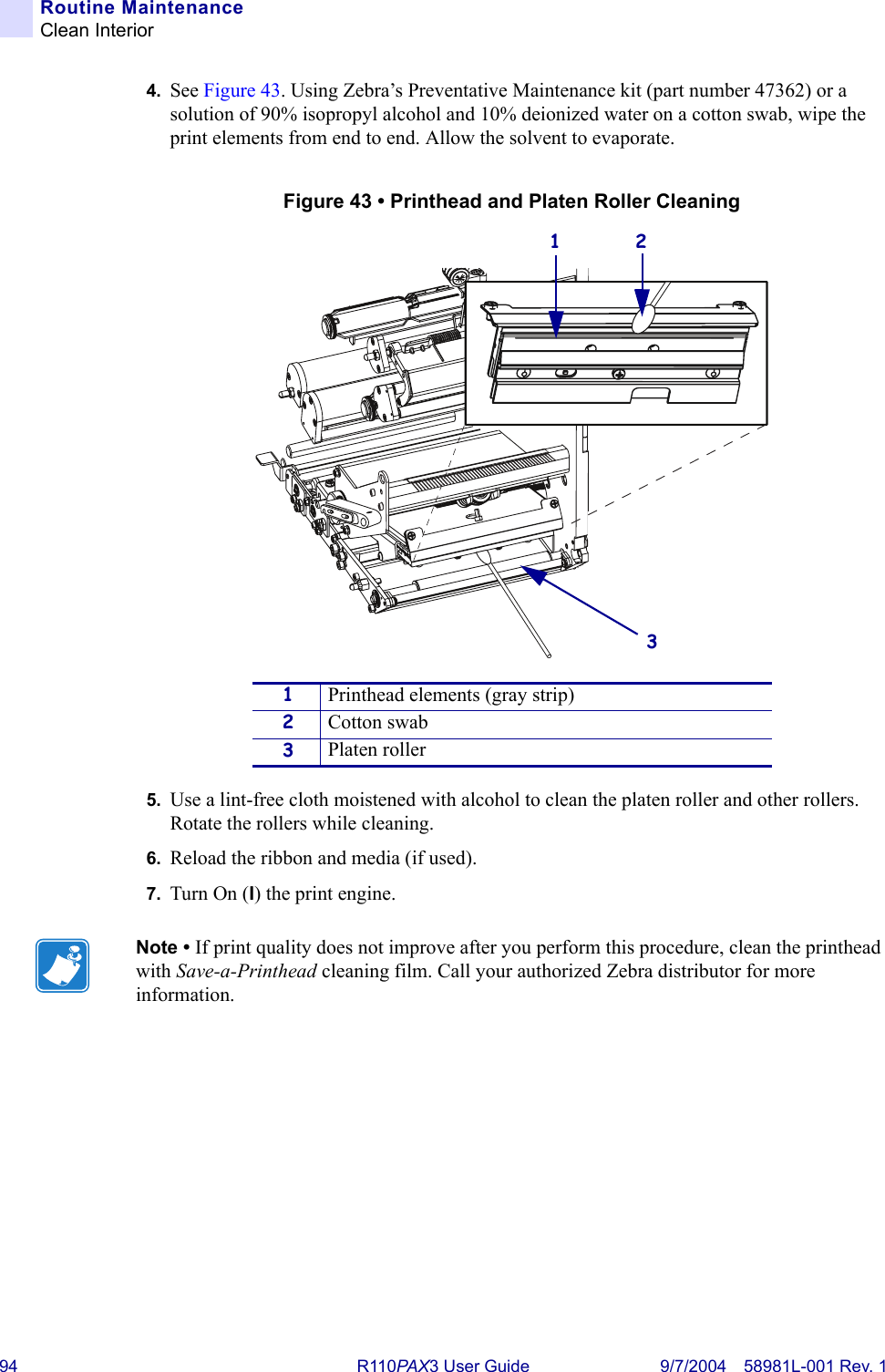
- 2. Users Manual Part 2
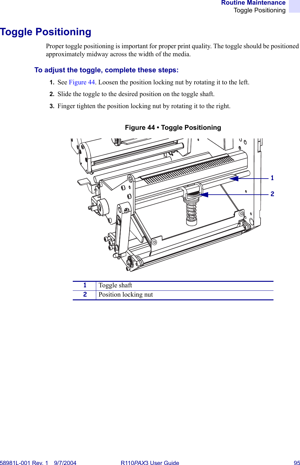
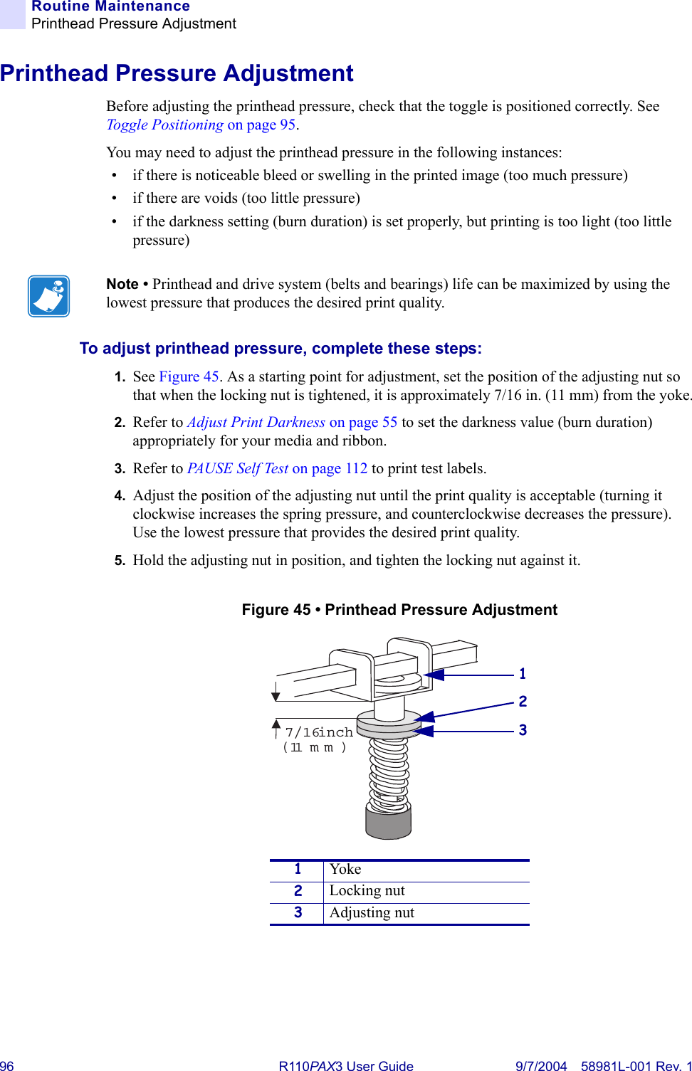
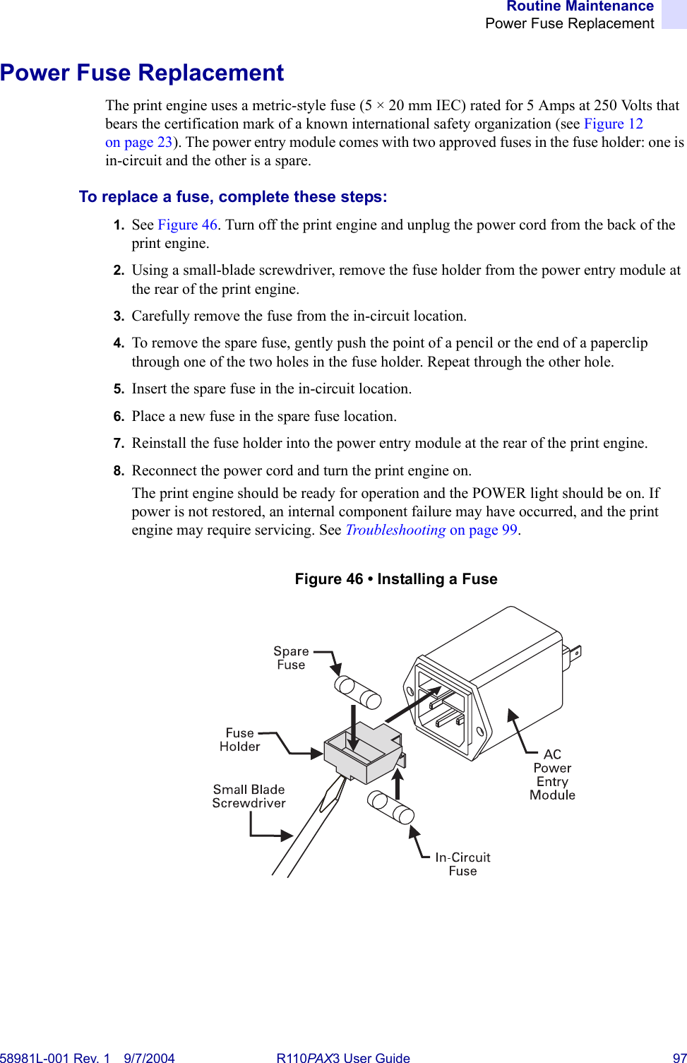
Users Manual Part 2
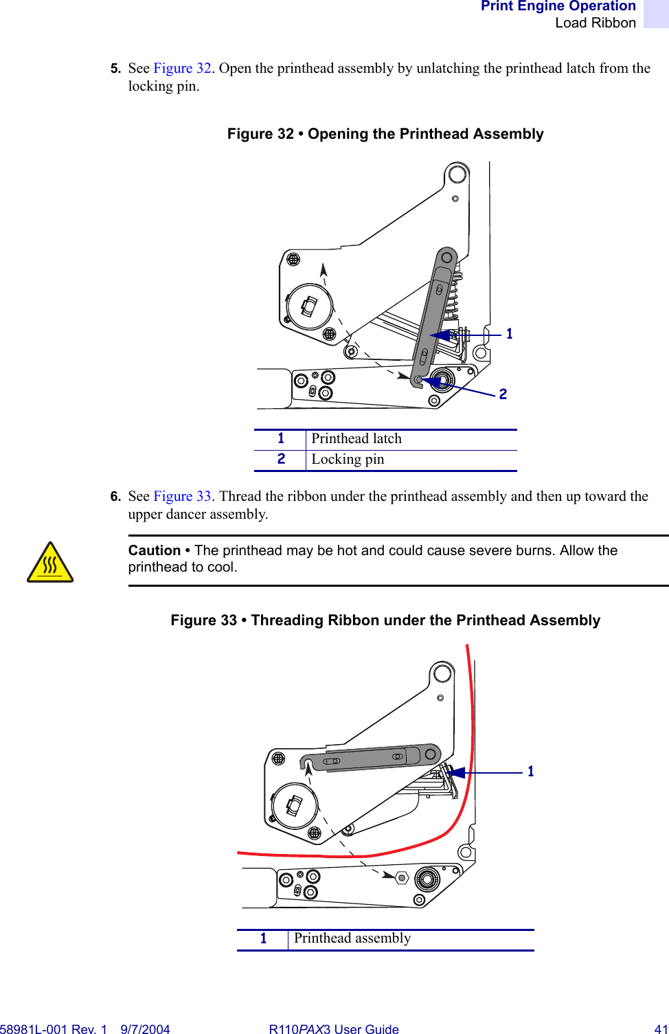

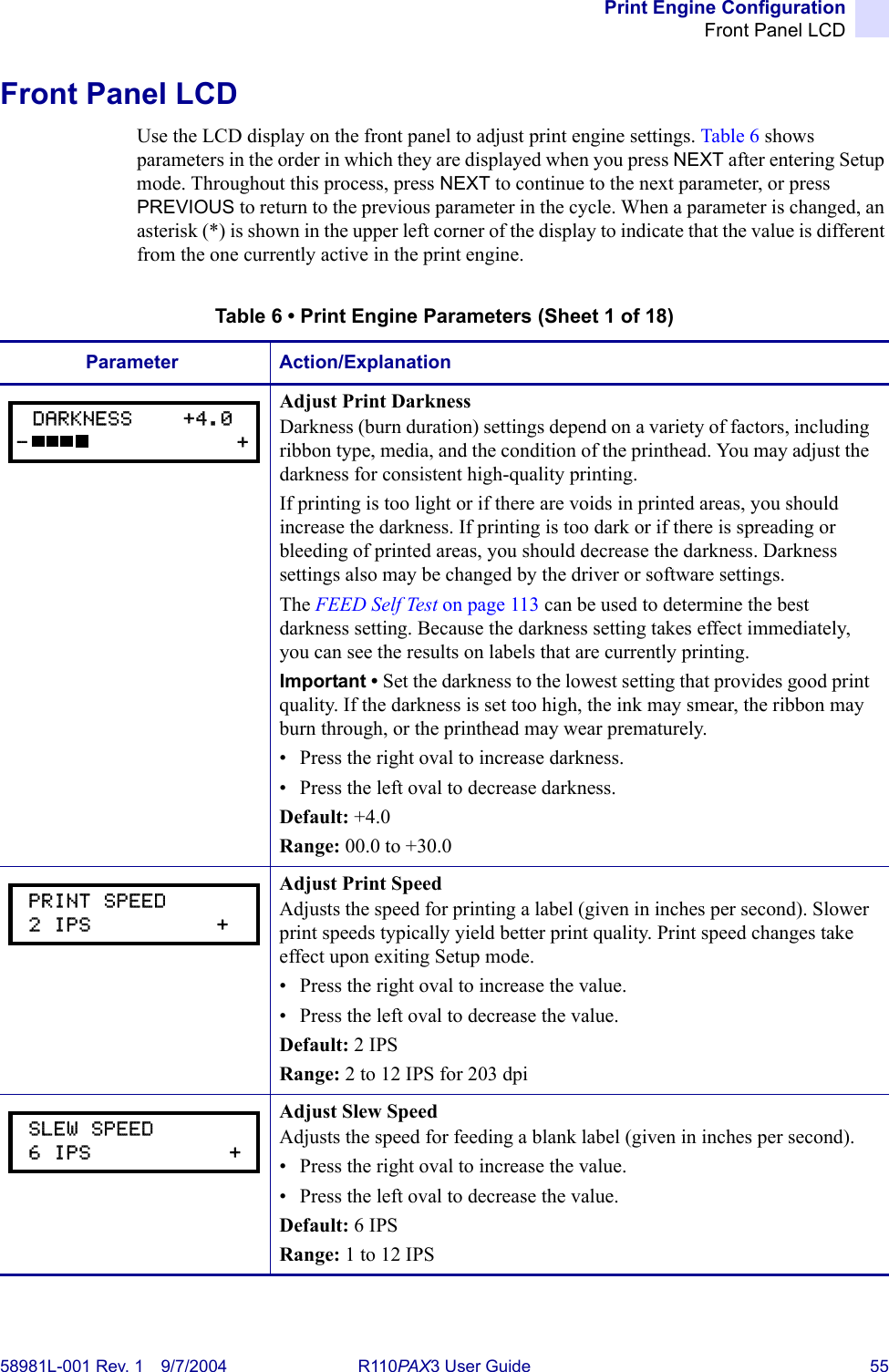
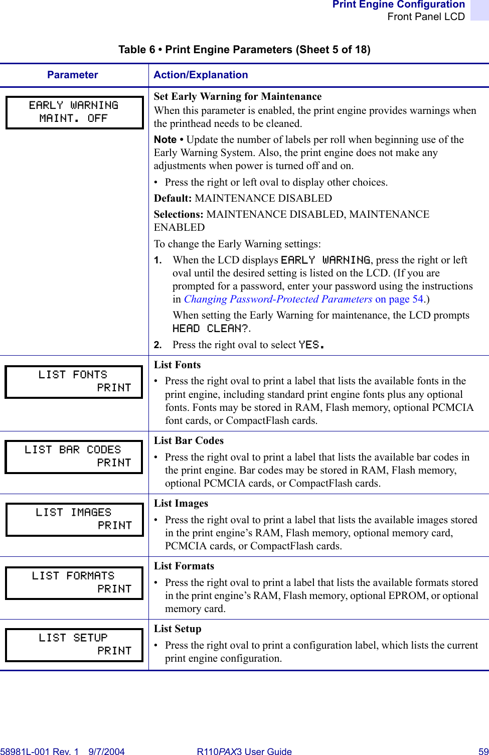
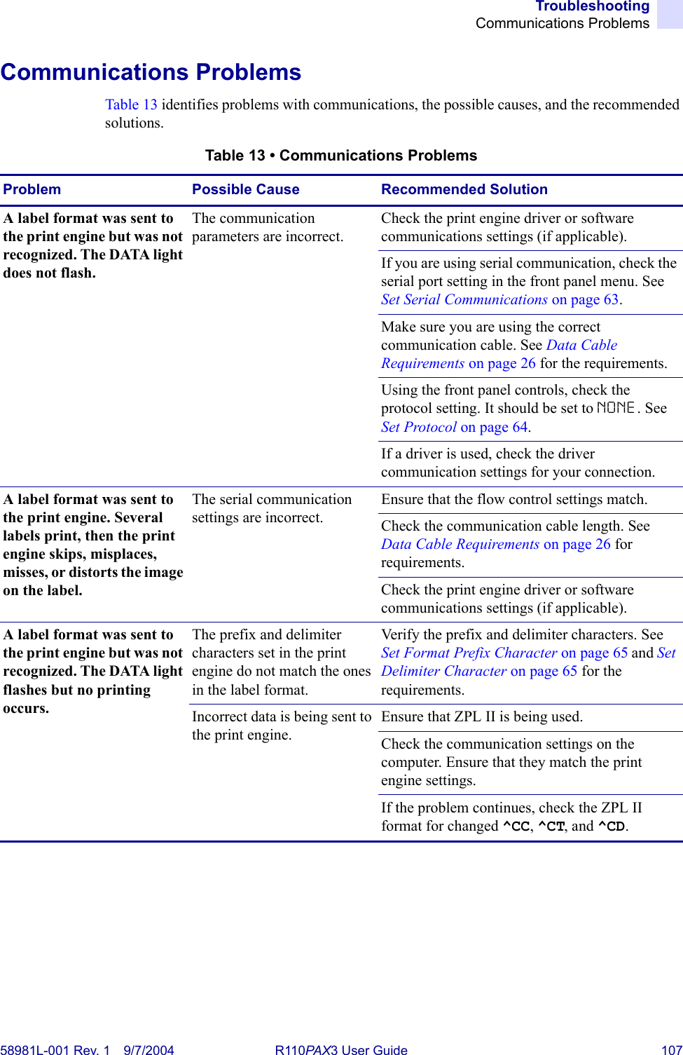
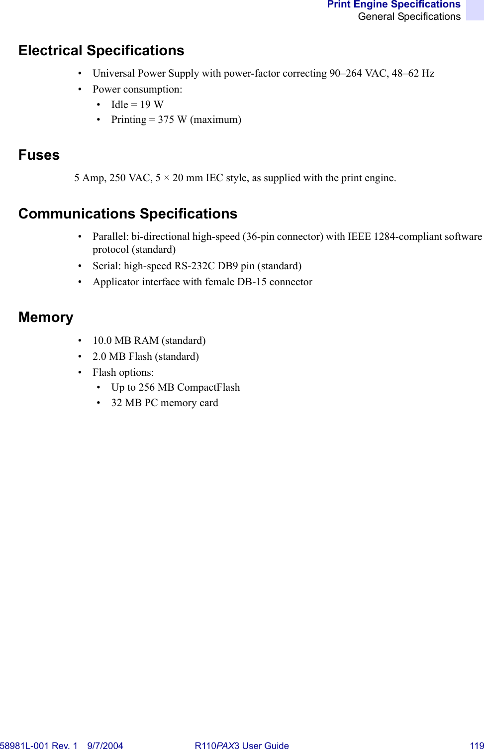
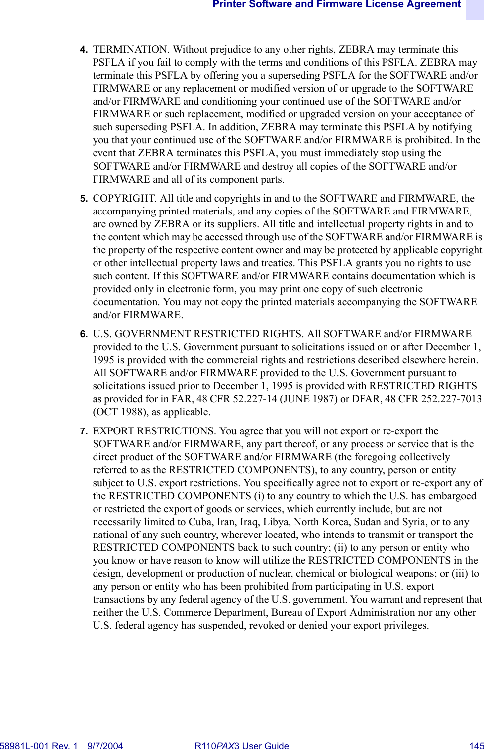
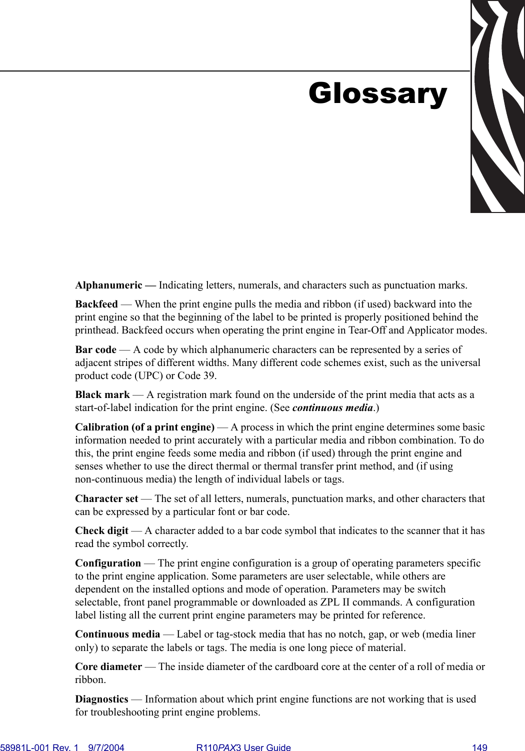
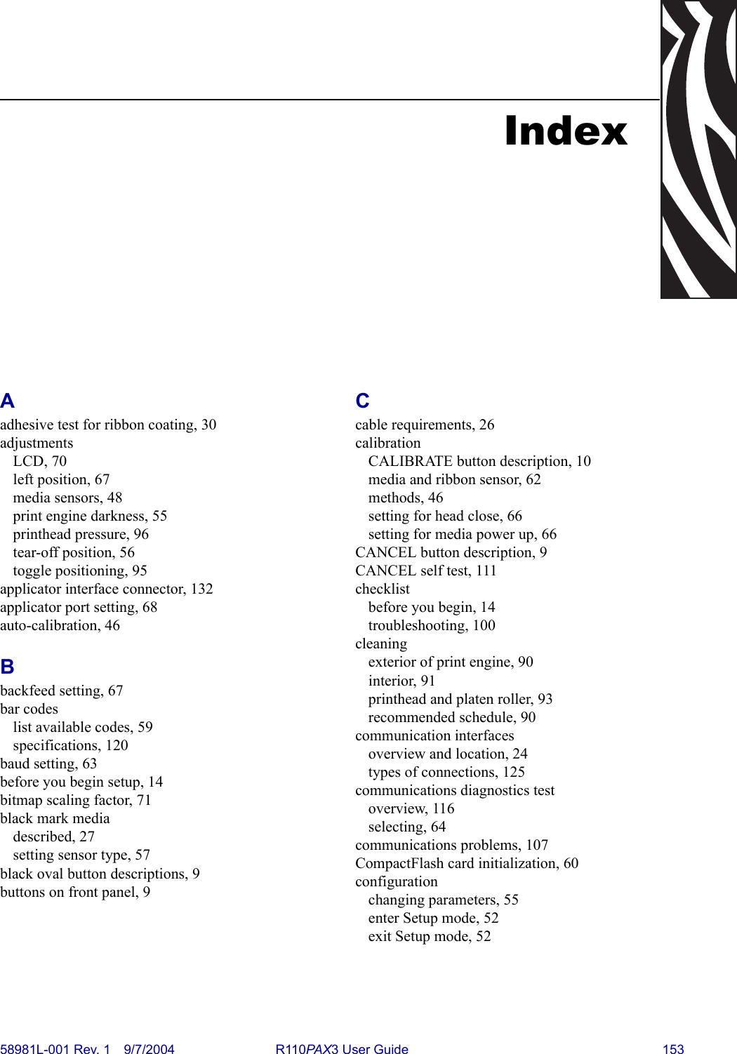
![RFID Guidelines^RS58981L-001 Rev. 1 9/7/2004 R110PAX3 User Guide 81Example 1 • This example sets the print engine to move the media to 800 dots from the top of the media [or label length minus 800 from the bottom (leading edge) of the media] and voids the rest of the media in case of an error. The print engine will try to print two labels, then will pause the print engine if printing and encoding fail.^XA^RS,800,,2,P^FS^XZThe following illustration shows the resulting voided label. Note where the void starts. The media has been moved 800 dot rows from the top of the label (label length minus 800 dot rows from the bottom (leading edge) of a label) to bring the transponder into the effective area to read/write a tag. If the print engine fails the operation, the rest of the media is voided.Top of labelStart of RFID operation800 dot rowsBottom of labelLabel length minus 800 dot rows](https://usermanual.wiki/Zebra-Technologies/RFID-R110PAX01.Users-Manual-Part-2/User-Guide-476094-Page-41.png)
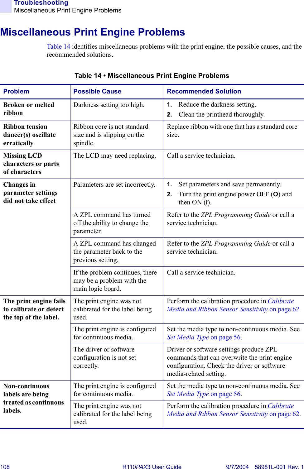
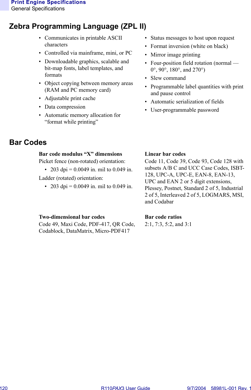
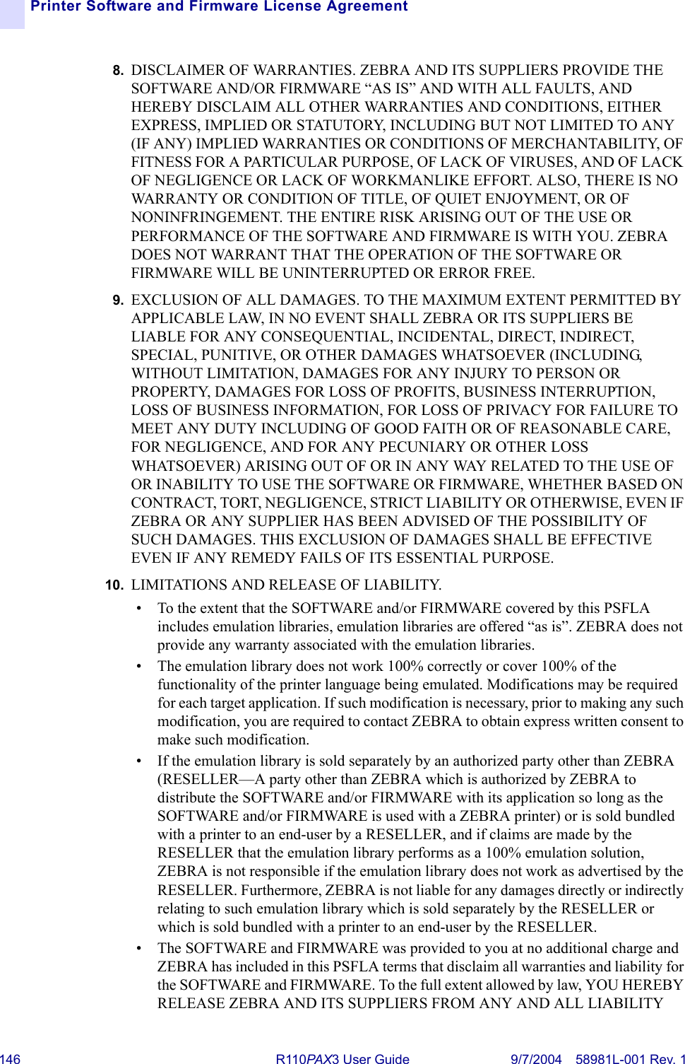
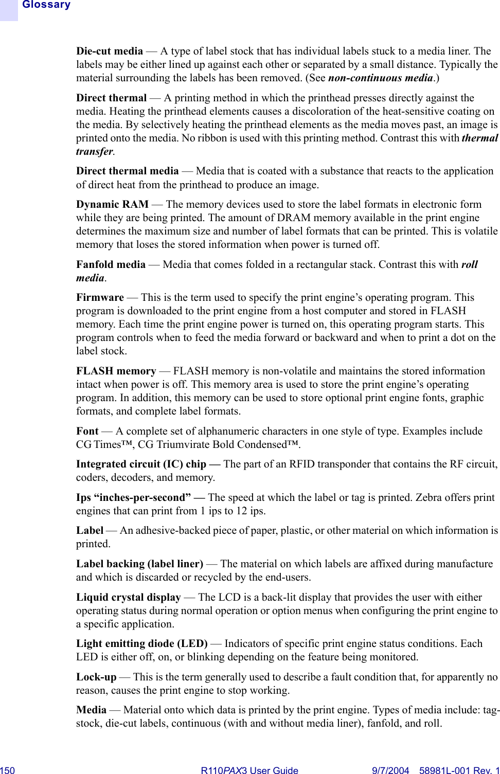
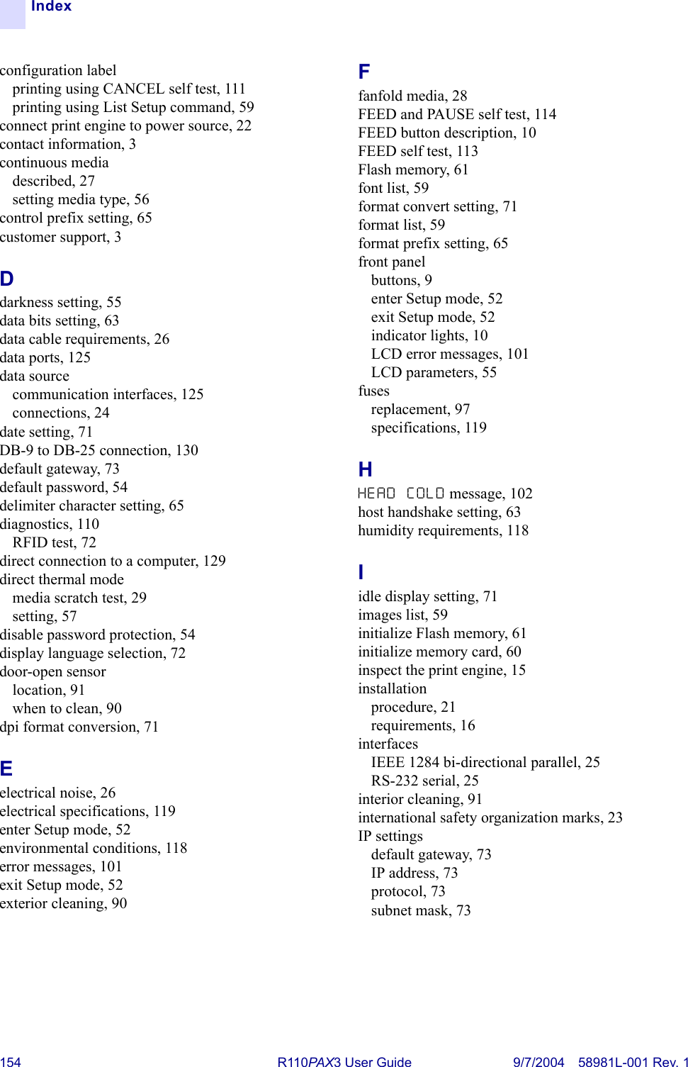
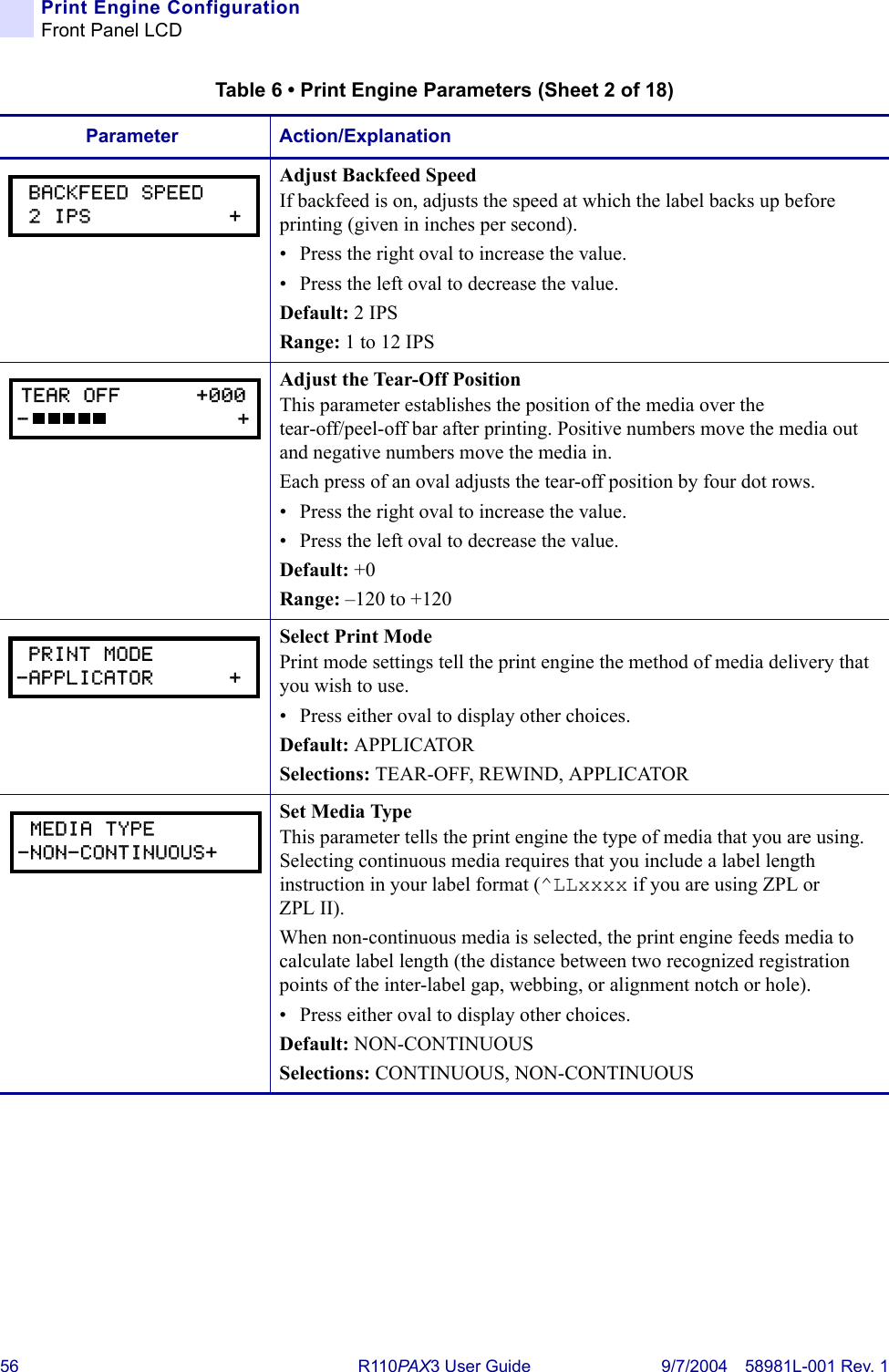
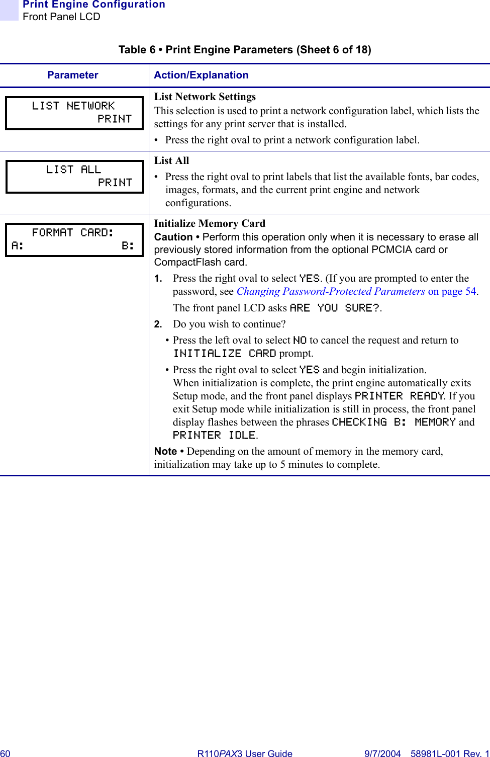
![82 R110PA X3 User Guide 9/7/2004 58981L-001 Rev. 1RFID Guidelines^RSExample 2 • This example sets the print engine to move the media to 800 dots from the top of the media [or label length - 500 from the bottom (leading edge) of the media] and prints “void” 500 dots in vertical length (Y axis) in case of an error.^XA^RS,800,500,2,P^FS^XZThe following illustration shows the resulting voided label. Note where the void starts. The media has been moved 800 dot rows from the top of the label [label length minus 800 dot rows from the bottom (leading edge) of a label] to bring the transponder into the effective area to read/write a tag. If the print engine fails the operation, an area that is 500 dot rows of the media is voided instead of the entire rest of the media.Top of labelStart of RFID operation800 dot rowsBottom of labelLabel length minus 800 dot rows500 dot rows](https://usermanual.wiki/Zebra-Technologies/RFID-R110PAX01.Users-Manual-Part-2/User-Guide-476094-Page-42.png)
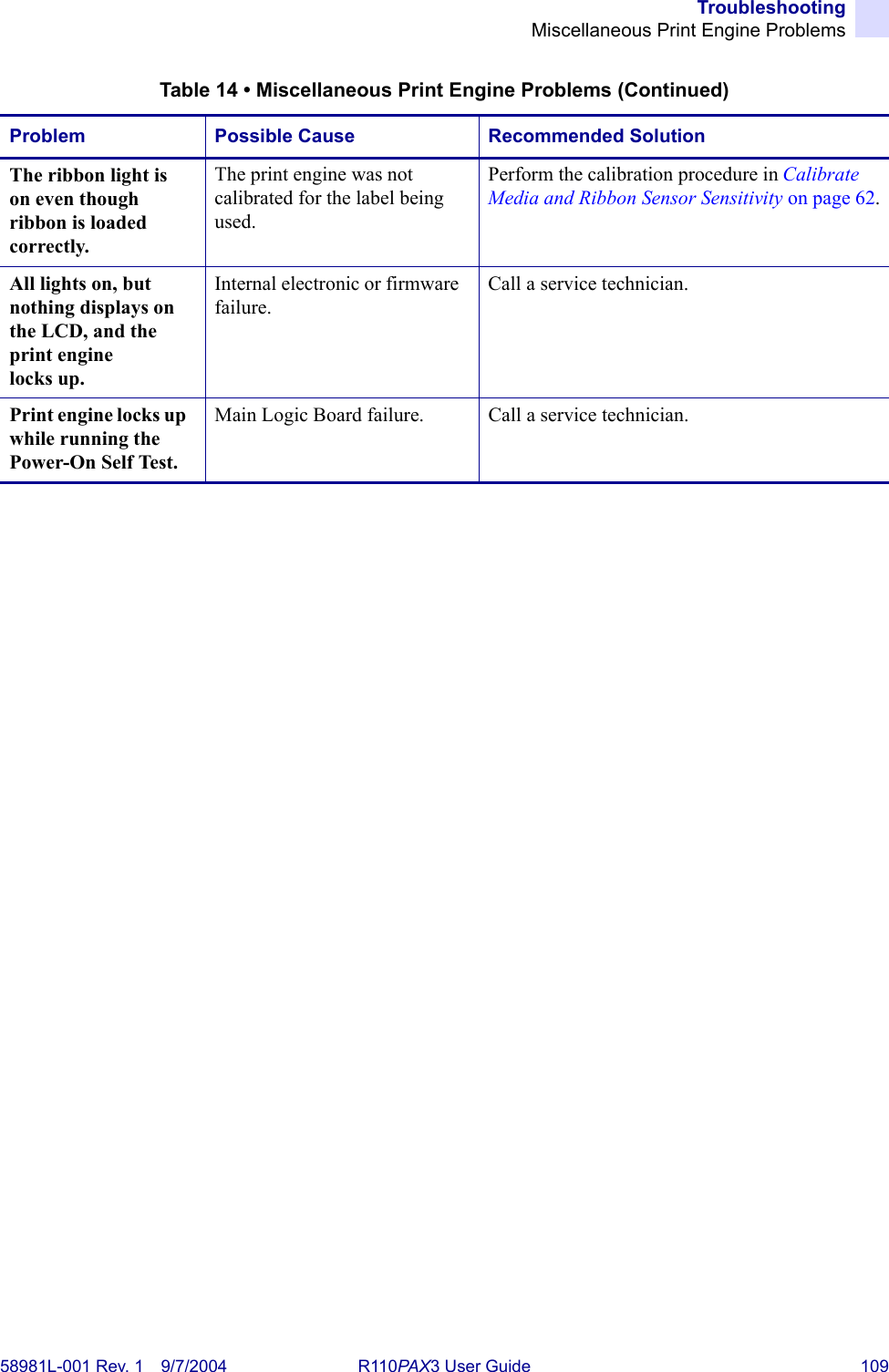
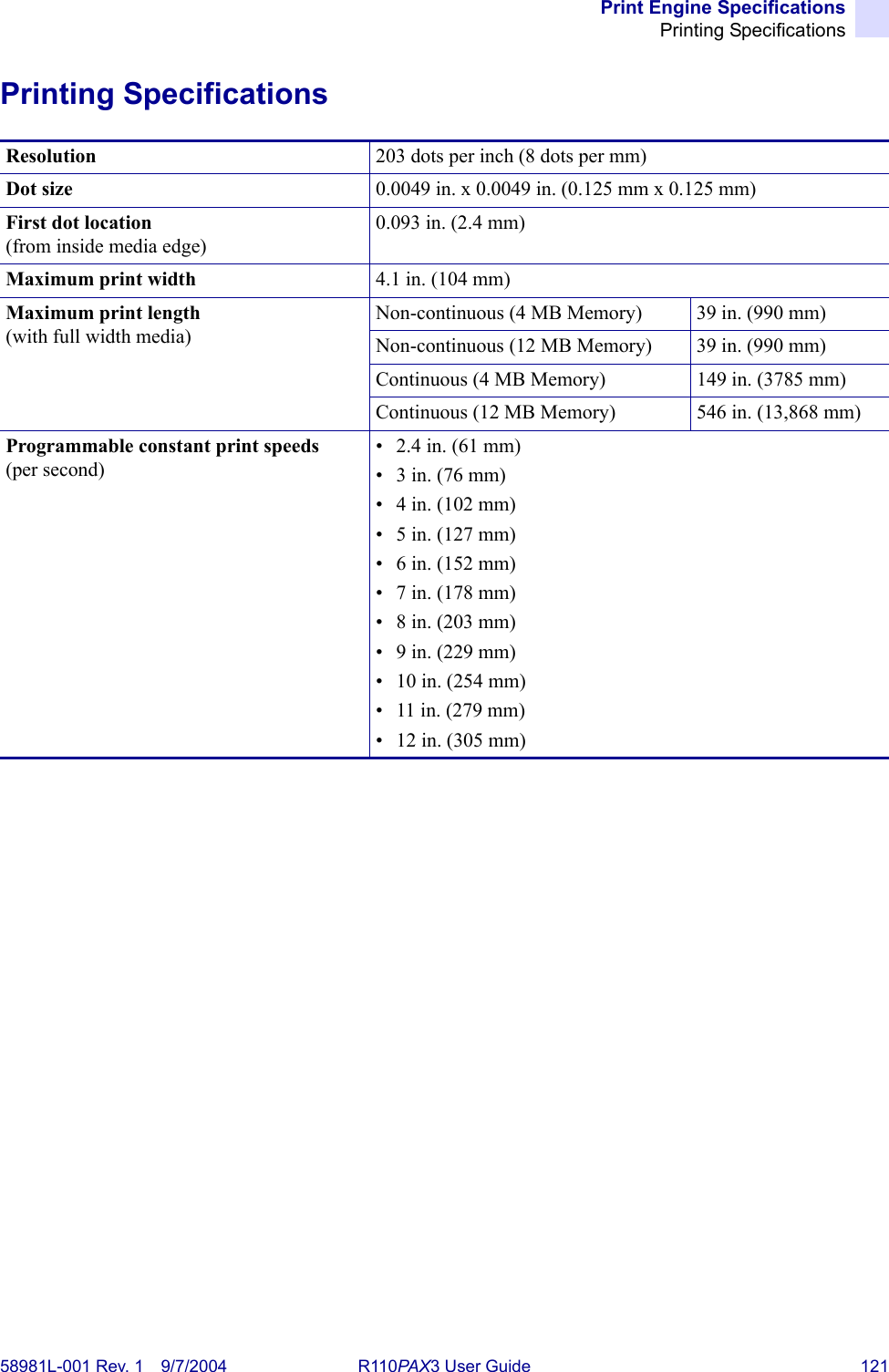
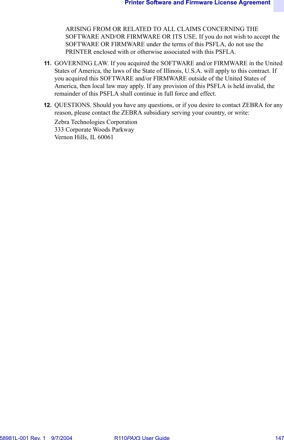
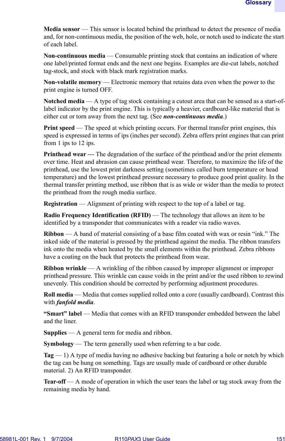
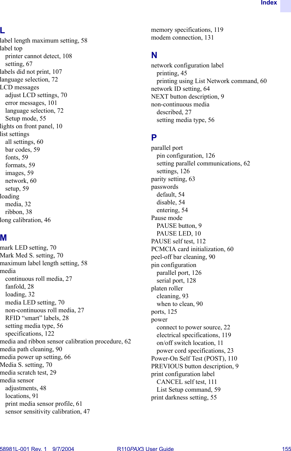
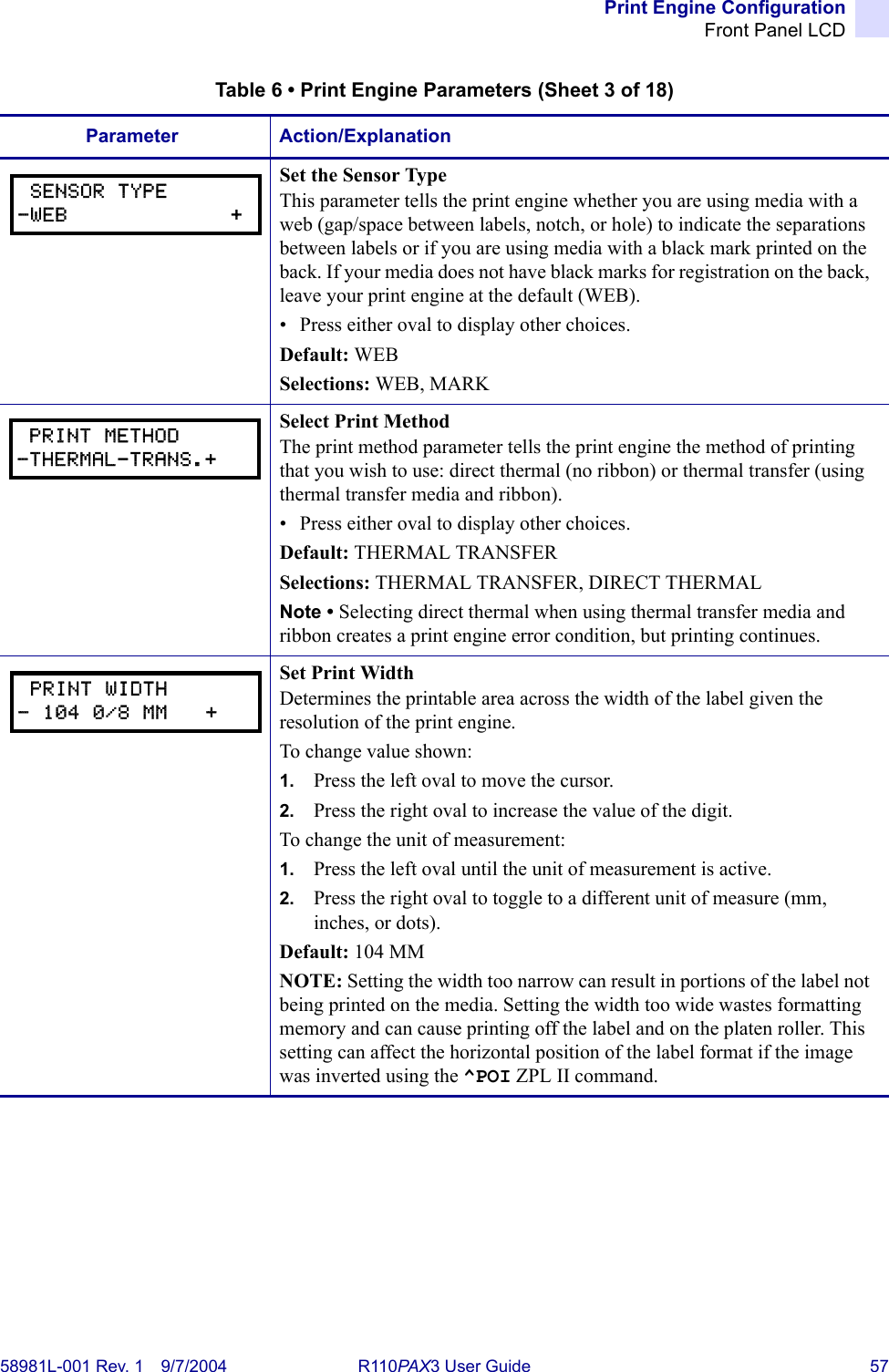
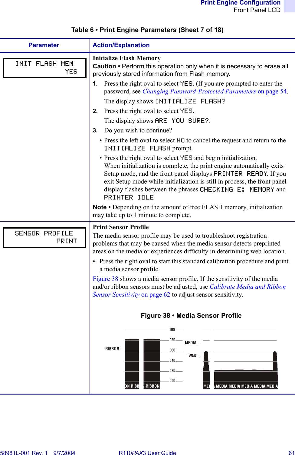
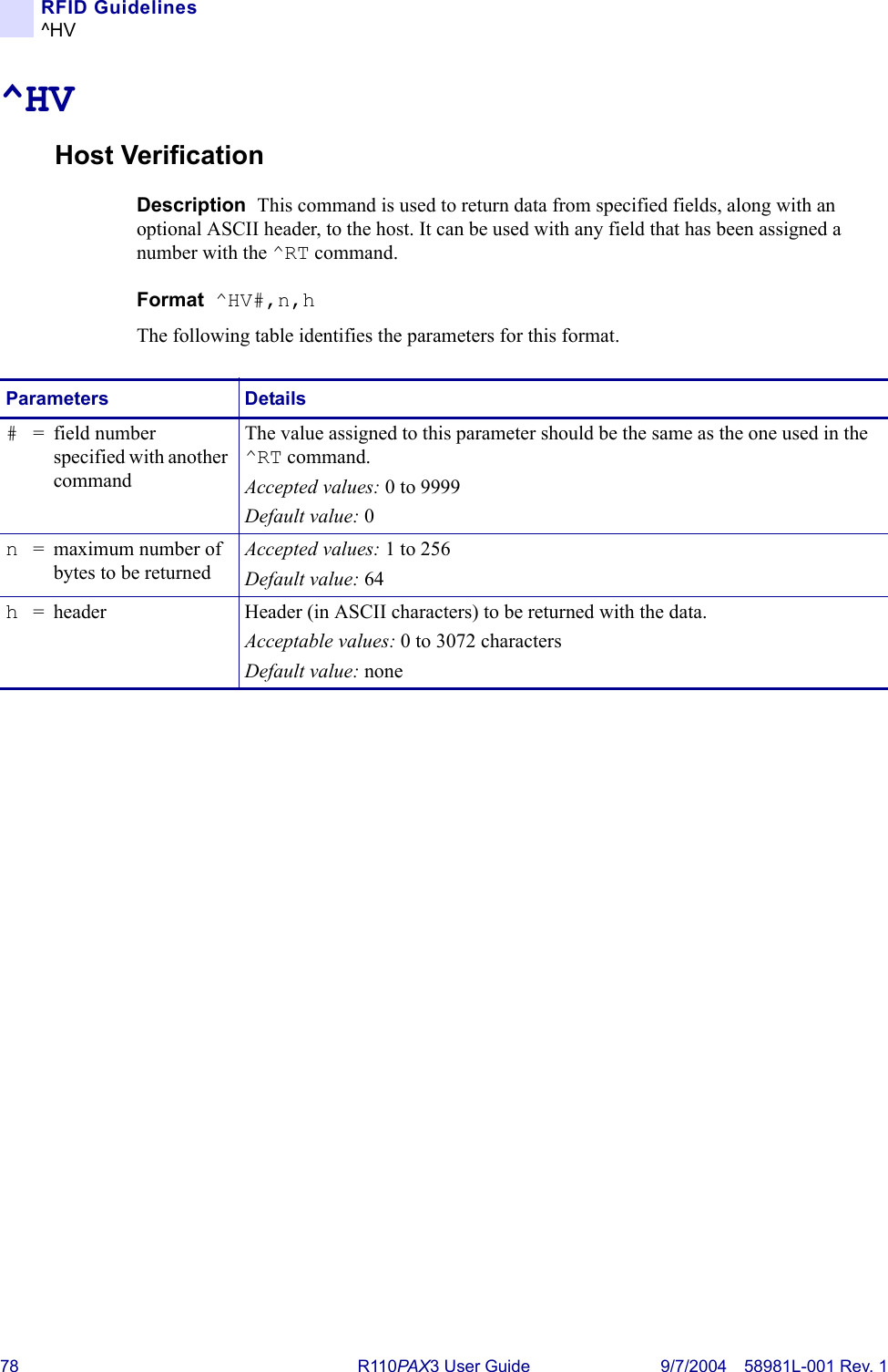
![RFID Guidelines^WT58981L-001 Rev. 1 9/7/2004 R110PAX3 User Guide 85^WTWrite TagDescription The ^WT command allows you to program the current RFID tag.Format ^WTb,r,m,w,f,vThe following table identifies the parameters for this format.Note • Check the amount of data memory available for the tag that you will be using. If more is sent than the memory can hold, the data will be truncated.Parameters Detailsb= block number* Accepted values: •0 (ID data/EPC)•1 (User data)Default value: 0r= number of retries The number of times that the command will be tried on the same tag.Accepted values: 0 to 10Default value: 0m= motion Accepted values:•0 (Feed label after writing.)•1 (No Feed after writing. Other ZPL may cause a feed.)Default value: 0w= write protect* Accepted values:•0 (Not write protected.)•1 (Write protect.)Default value: 0f= data format Accepted values:•0 (ASCII)•1 (Hexadecimal)Default value: 0v= verify valid data*Default value: YAccepted values:•N (Do not verify)•Y (Verify valid data [Hex A5A5 in the first two bytes] before writing)* Not applicable for R110PAX.](https://usermanual.wiki/Zebra-Technologies/RFID-R110PAX01.Users-Manual-Part-2/User-Guide-476094-Page-45.png)