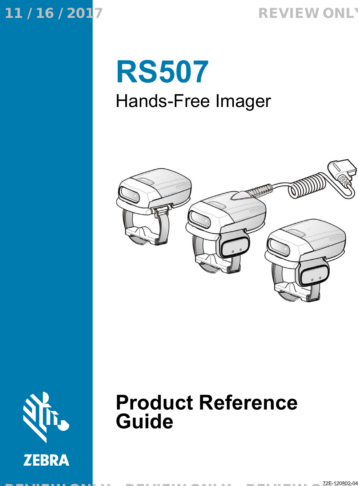
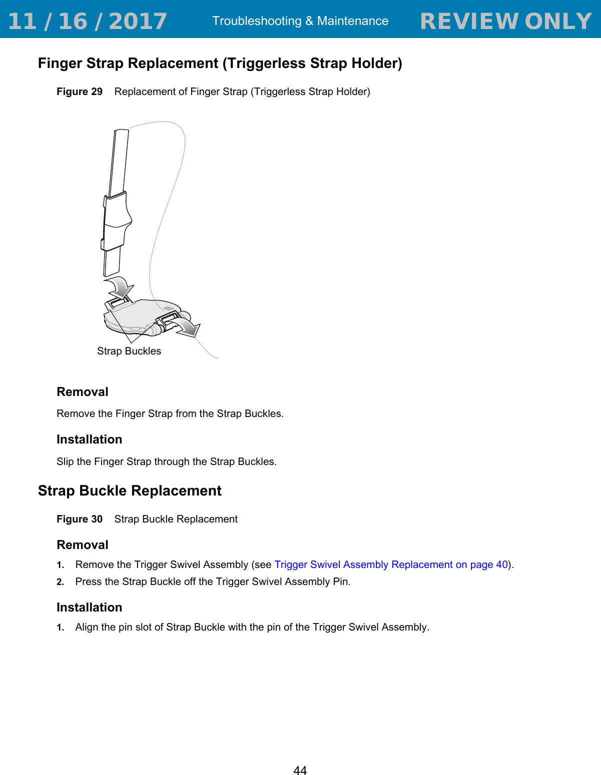
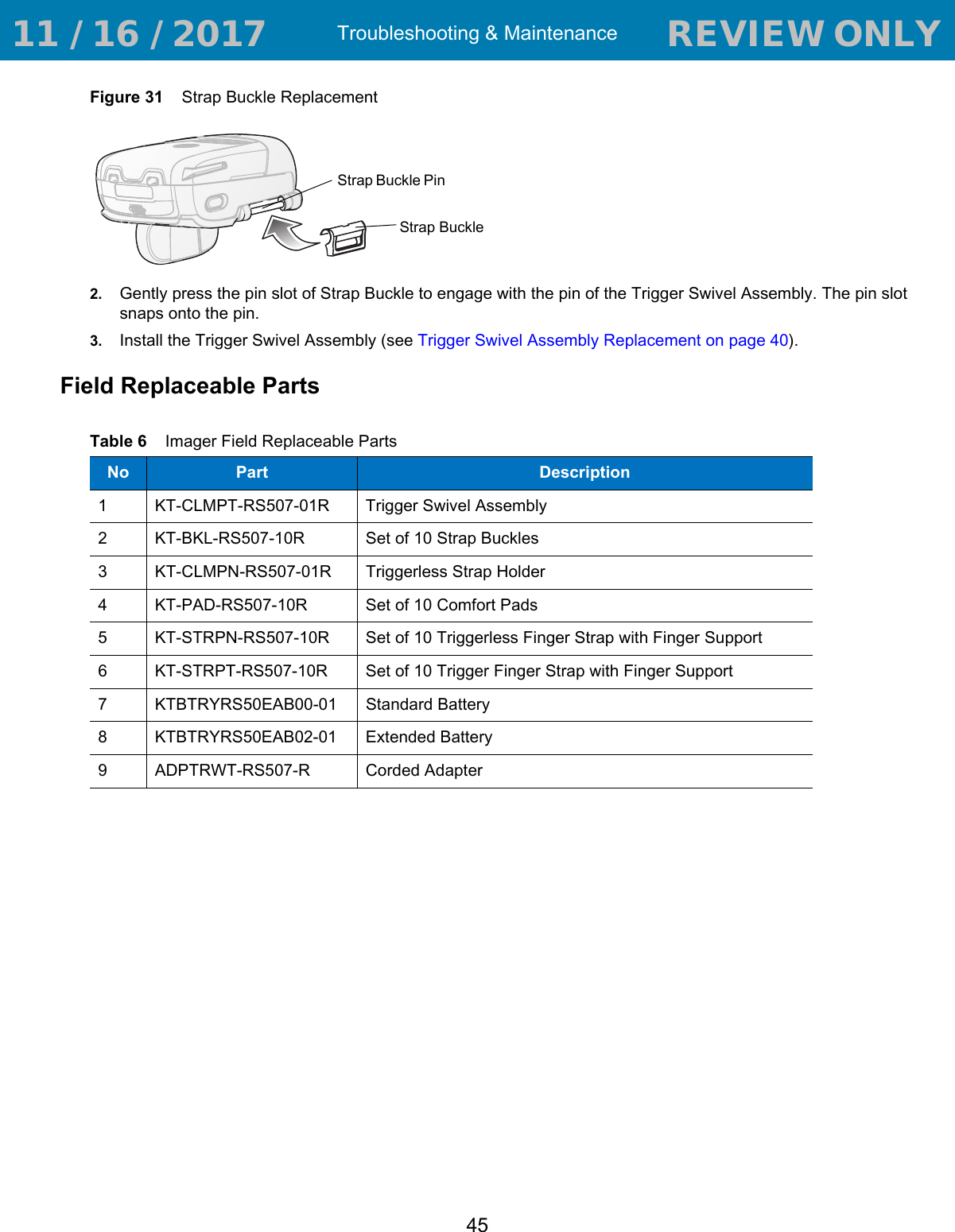
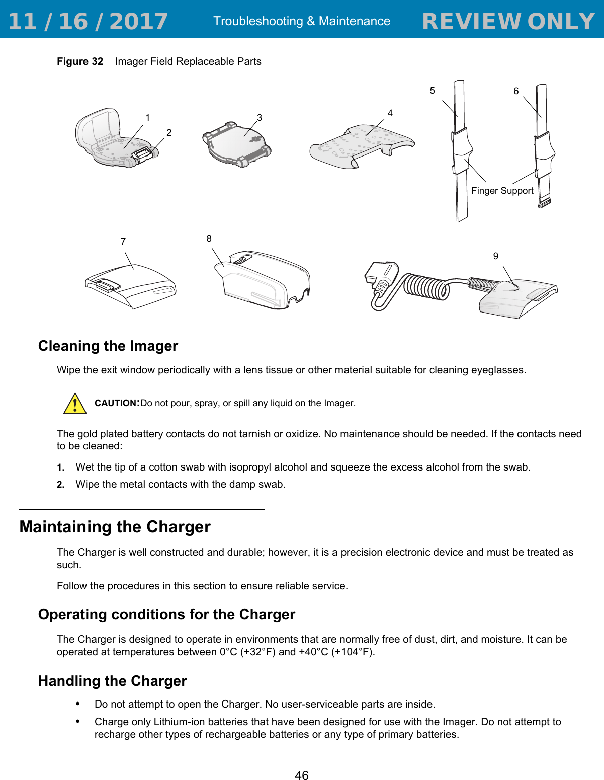
Zebra Technologies RS507X Hands Free Imager User Manual RS507 Product Reference Guide en
Zebra Technologies Corporation Hands Free Imager RS507 Product Reference Guide en
Contents
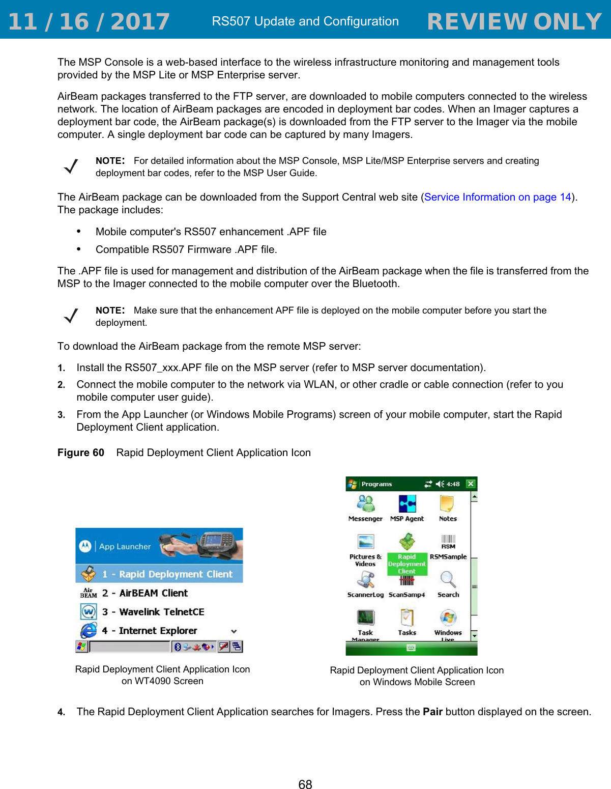
- 1. User Manual 1
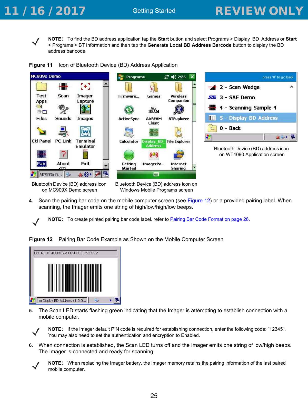
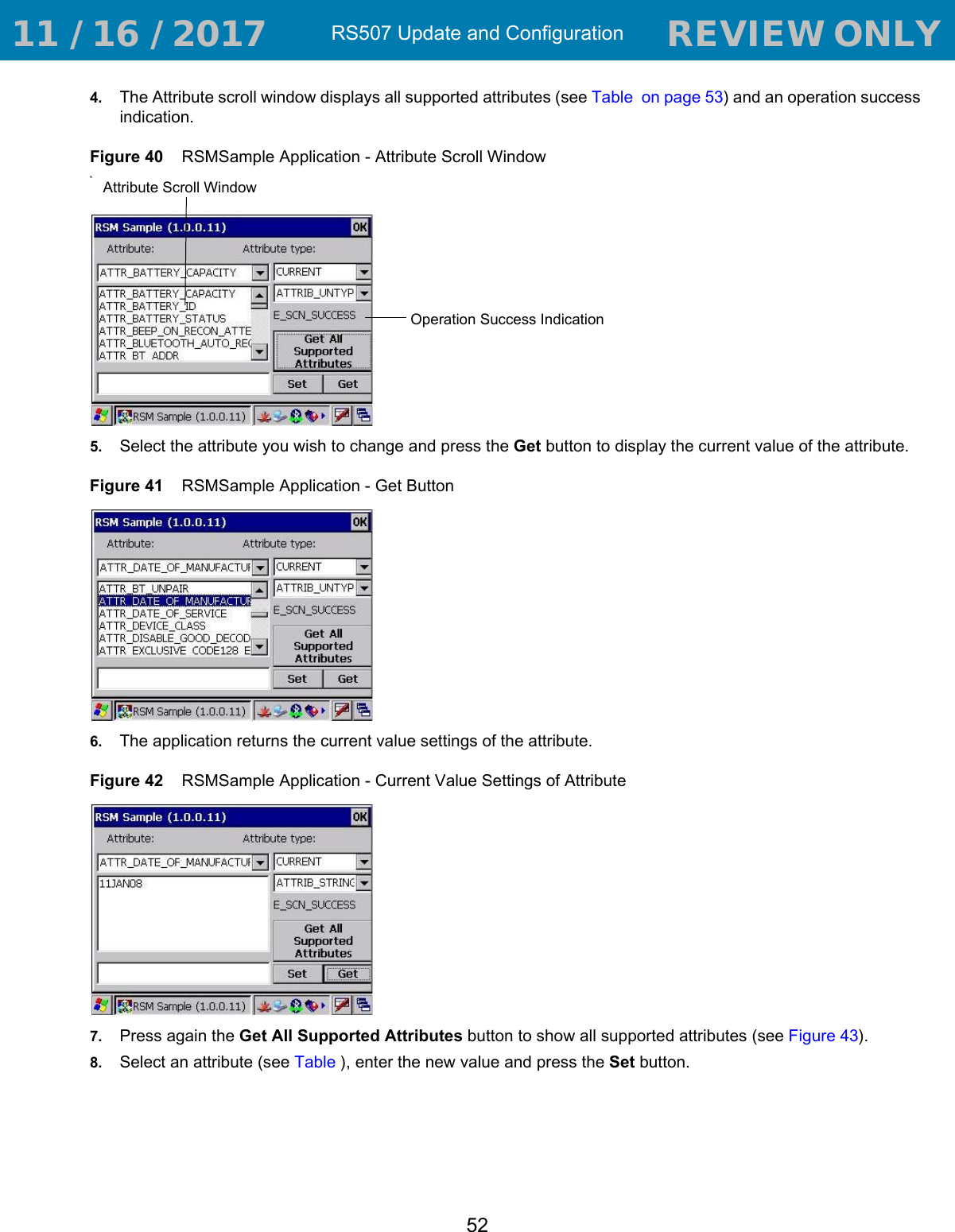
- 2. User Manual 2
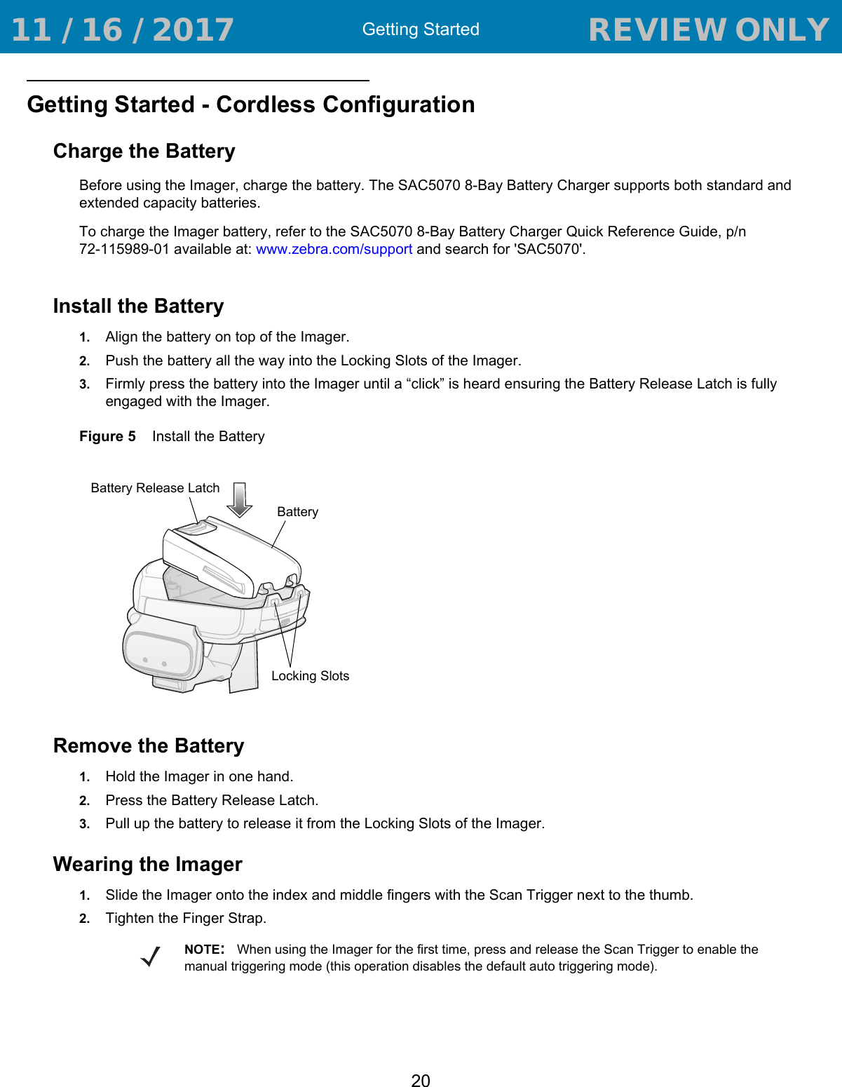
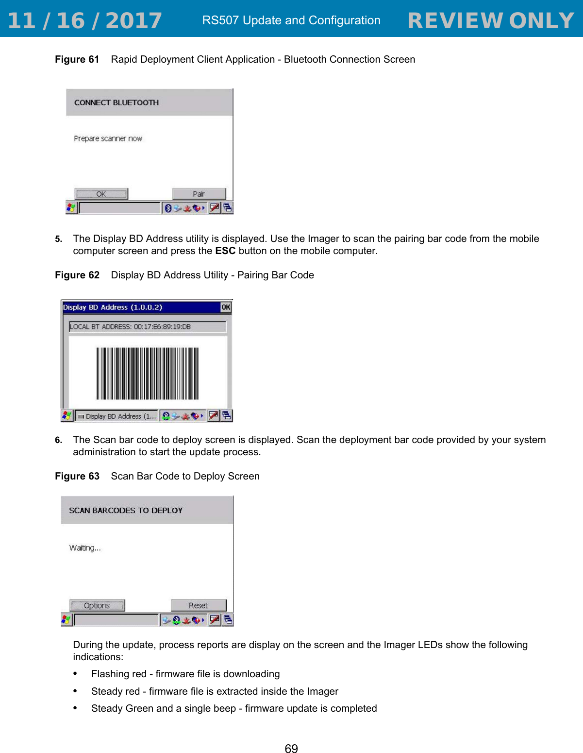
- 3. User Manual Regulatory
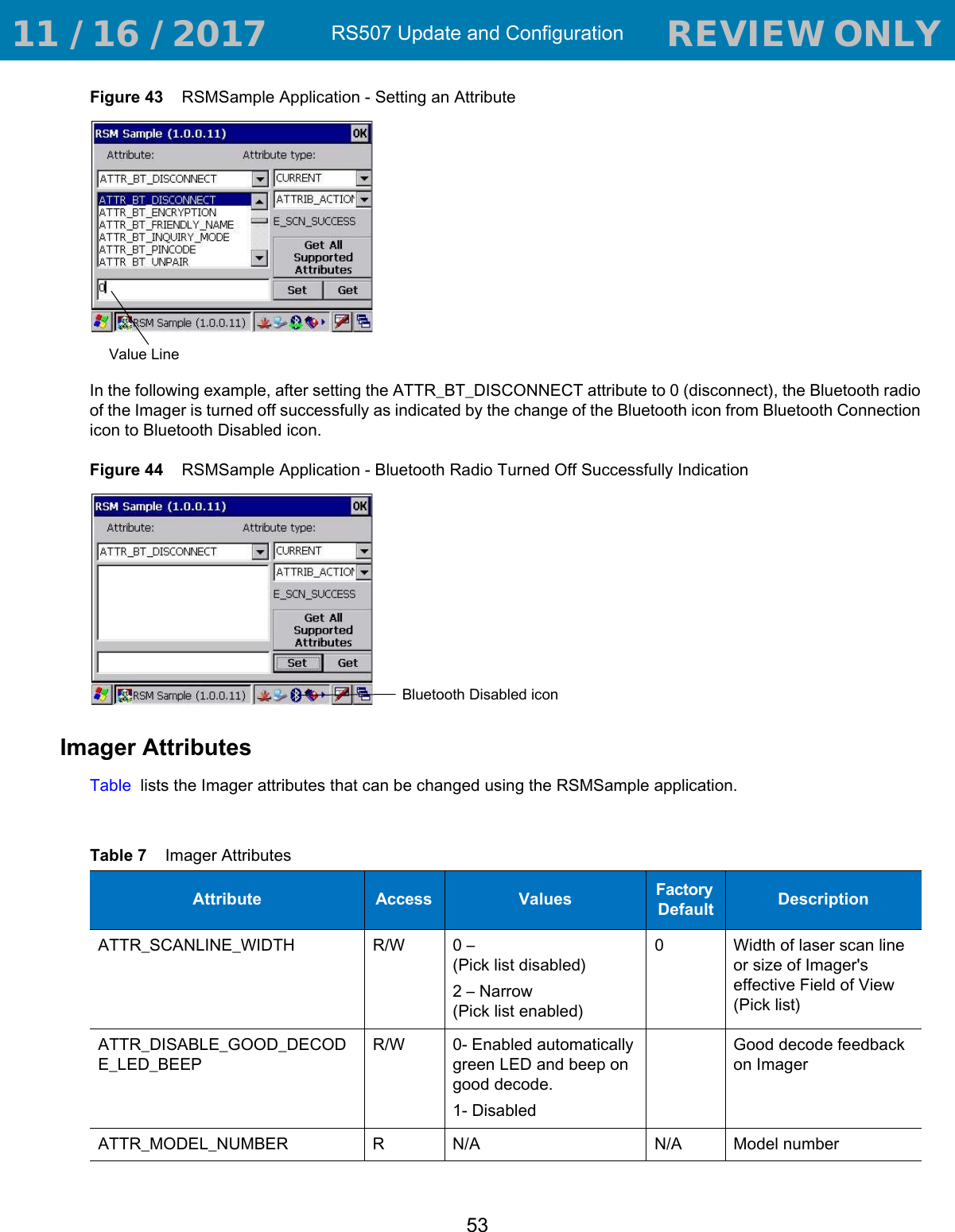
User Manual 1