Zebra Technologies RS507X Hands Free Imager User Manual RS507 Product Reference Guide en
Zebra Technologies Corporation Hands Free Imager RS507 Product Reference Guide en
Contents
- 1. User Manual 1
- 2. User Manual 2
- 3. User Manual Regulatory
User Manual 1
Hands-Free Imager
RS507
72E-120802-04
Product Reference
Guide
11 / 16 / 2017 REVIEW ONLY
REVIEW ONLY - REVIEW ONLY - REVIEW ONLY

2
Copyright
© 2017 ZIH Corp. and/or its affiliates. All rights reserved. ZEBRA and the stylized Zebra head are trademarks of
ZIH Corp., registered in many jurisdictions worldwide. All other trademarks are the property of their respective
owners.
COPYRIGHTS & TRADEMARKS: For complete copyright and trademark information, go to www.zebra.com/
copyright.
WARRANTY: For complete warranty information, go to www.zebra.com/warranty.
END USER LICENSE AGREEMENT: For complete EULA information, go to www.zebra.com/eula.
Terms of Use
• Proprietary Statement
This manual contains proprietary information of Zebra Technologies Corporation and its subsidiaries
(“Zebra Technologies”). It is intended solely for the information and use of parties operating and
maintaining the equipment described herein. Such proprietary information may not be used, reproduced,
or disclosed to any other parties for any other purpose without the express, written permission of Zebra
Technologies.
• Product Improvements
Continuous improvement of products is a policy of Zebra Technologies. All specifications and designs are
subject to change without notice.
• Liability Disclaimer
Zebra Technologies takes steps to ensure that its published Engineering specifications and manuals are
correct; however, errors do occur. Zebra Technologies reserves the right to correct any such errors and
disclaims liability resulting therefrom.
• Limitation of Liability
In no event shall Zebra Technologies or anyone else involved in the creation, production, or delivery of the
accompanying product (including hardware and software) be liable for any damages whatsoever
(including, without limitation, consequential damages including loss of business profits, business
interruption, or loss of business information) arising out of the use of, the results of use of, or inability to
use such product, even if Zebra Technologies has been advised of the possibility of such damages. Some
jurisdictions do not allow the exclusion or limitation of incidental or consequential damages, so the above
limitation or exclusion may not apply to you.
Revision History
Changes to the original guide are listed below:
Change Date Description
-01 Rev A 10/2009 Release
-01 Rev B 10/2011 Add Chapter 7
-02 Rev A 3/2015 Zebra rebranding
11 / 16 / 2017 REVIEW ONLY
REVIEW ONLY - REVIEW ONLY - REVIEW ONLY

3
-03 Rev A 4/2017 Correct LED indicator indications in Table 2.
-04 Rev A 11/2017 Add model number RS507X
Change Date Description
11 / 16 / 2017 REVIEW ONLY
REVIEW ONLY - REVIEW ONLY - REVIEW ONLY

4
Table of Contents
Copyright ........................................................................................................................................... 2
Terms of Use .................................................................................................................................... 2
Revision History ................................................................................................................................ 2
About This Guide
Introduction ..................................................................................................................................... 12
Documentation Set ......................................................................................................................... 12
Model Configurations ...................................................................................................................... 12
Chapter Descriptions ...................................................................................................................... 13
Notational Conventions ................................................................................................................... 13
Related Documents ........................................................................................................................ 14
Service Information ......................................................................................................................... 14
Provide Documentation Feedback .................................................................................................. 14
Getting Started
Introduction ..................................................................................................................................... 15
Unpacking ....................................................................................................................................... 15
Introduction ..................................................................................................................................... 15
Cordless Configuration Features .................................................................................................... 17
Corded Configuration Features ....................................................................................................... 18
Trigger Swivel Assembly - Change Trigger Position ................................................................. 19
Getting Started - Cordless Configuration ........................................................................................ 20
Charge the Battery .................................................................................................................... 20
Install the Battery ...................................................................................................................... 20
Remove the Battery .................................................................................................................. 20
Wearing the Imager ................................................................................................................... 20
Getting Started - Corded Configuration .......................................................................................... 21
Connect the Corded Adapter .................................................................................................... 21
Remove the Corded Adapter .................................................................................................... 21
Connect to a WT4090 Wearable Terminal ................................................................................ 22
Wearing the Imager ................................................................................................................... 22
Status Indications ............................................................................................................................ 23
Imager Standby Mode ..................................................................................................................... 24
Bluetooth Connection ...................................................................................................................... 24
Establish Bluetooth Connection ................................................................................................ 24
Restore Lost Bluetooth Connection .......................................................................................... 26
11 / 16 / 2017 REVIEW ONLY
REVIEW ONLY - REVIEW ONLY - REVIEW ONLY

Table of Contents
5
Remove Bluetooth Connection ................................................................................................. 26
Pairing Bar Code Format .......................................................................................................... 26
Scan ................................................................................................................................................ 27
Scan Triggering Modes ............................................................................................................. 27
Aiming the Imager ..................................................................................................................... 28
Customize the Imager ..................................................................................................................... 29
Changing from Triggered to Triggerless Configuration ............................................................. 29
Changing Triggerless to Triggered Configuration ..................................................................... 29
Resetting the Imager ....................................................................................................................... 30
Warm Boot ................................................................................................................................ 30
Cold Boot .................................................................................................................................. 30
Clean Boot ................................................................................................................................ 30
SAC5070 8-Bay Battery Charger
Introduction ..................................................................................................................................... 31
Unpacking the Charger ................................................................................................................... 31
Parts of the Charger ........................................................................................................................ 32
Installation ....................................................................................................................................... 33
Tabletop / Shelf Set Up ............................................................................................................. 33
Wall Mount ................................................................................................................................ 33
Inserting the Imager Battery in the Charger .................................................................................... 34
Charge the Battery .................................................................................................................... 35
Battery Age Test ............................................................................................................................. 35
Charge Status LED ................................................................................................................... 36
Troubleshooting & Maintenance
Introduction ..................................................................................................................................... 37
Troubleshooting .............................................................................................................................. 37
Imager ....................................................................................................................................... 37
Charger ..................................................................................................................................... 38
Maintenance ................................................................................................................................... 39
Maintaining the Imager ................................................................................................................... 39
Comfort Pad Replacement ........................................................................................................ 39
Trigger Swivel Assembly Replacement ..................................................................................... 40
Triggerless Strap Holder Replacement ............................................................................................... 41
Finger Strap Replacement (Trigger Swivel Assembly) ............................................................. 42
Finger Strap Replacement (Triggerless Strap Holder) .............................................................. 44
Strap Buckle Replacement ........................................................................................................ 44
Field Replaceable Parts ............................................................................................................ 45
Cleaning the Imager .................................................................................................................. 46
Maintaining the Charger .................................................................................................................. 46
Operating conditions for the Charger ........................................................................................ 46
Handling the Charger ................................................................................................................ 46
Cleaning the Charger ................................................................................................................ 47
RS507 Update and Configuration
Introduction ..................................................................................................................................... 48
Configuring the Imager ................................................................................................................... 48
11 / 16 / 2017 REVIEW ONLY
REVIEW ONLY - REVIEW ONLY - REVIEW ONLY

Table of Contents
6
Introduction ............................................................................................................................... 48
Control Panel Application .......................................................................................................... 49
RSMSample Application ........................................................................................................... 50
Imager Attributes ....................................................................................................................... 53
Imager Motion and Proximity Configuration .............................................................................. 57
.................................................................................................................................................. 61
Real Time Logger ........................................................................................................................... 61
ScannerLog Application ......................................................................................................................... 62
Imager Firmware Update ................................................................................................................ 64
Required Equipment ................................................................................................................. 64
Updating the RS507 Firmware .................................................................................................. 65
Rapid Deployment Client ................................................................................................................ 67
Miscellaneous Imager Options
Introduction ..................................................................................................................................... 70
Scanning Sequence Examples ....................................................................................................... 70
Errors While Scanning .................................................................................................................... 71
User Preferences/Miscellaneous Options Parameter Defaults ....................................................... 71
User Preferences ............................................................................................................................ 72
Set Default Parameter ............................................................................................................... 72
Parameter Bar Code Scanning ................................................................................................. 73
Beep After Good Decode .......................................................................................................... 74
Beeper Tone ............................................................................................................................. 75
Beeper Volume ......................................................................................................................... 76
Imager Activity Modes ............................................................................................................... 77
Picklist Mode ............................................................................................................................. 78
Fuzzy 1D Processing ................................................................................................................ 79
Decoding Illumination ................................................................................................................ 80
Low Battery Indication Cycle ..................................................................................................... 80
Bluetooth Disconnection Alert Control ...................................................................................... 81
Miscellaneous Scanner Parameters ............................................................................................... 83
Transmit Code ID Character ..................................................................................................... 83
Prefix/Suffix Values ................................................................................................................... 84
Scan Data Transmission Format ............................................................................................... 85
Scan Data Transmission Format (continued) ............................................................................ 87
FN1 Substitution Values ............................................................................................................ 87
Transmit “No Read” Message ................................................................................................... 88
Symbologies
Introduction ..................................................................................................................................... 89
Scanning Sequence Examples ....................................................................................................... 89
Errors While Scanning .................................................................................................................... 90
Symbology Parameter Defaults ...................................................................................................... 90
UPC/EAN ........................................................................................................................................ 99
Enable/Disable UPC-A .............................................................................................................. 99
Enable/Disable UPC-E .............................................................................................................. 99
Enable/Disable UPC-E1 ............................................................................................................ 99
Enable/Disable EAN-8/JAN-8 ................................................................................................. 100
Enable/Disable EAN-13/JAN-13 ............................................................................................. 101
11 / 16 / 2017 REVIEW ONLY
REVIEW ONLY - REVIEW ONLY - REVIEW ONLY

Table of Contents
7
Enable/Disable Bookland EAN ................................................................................................ 101
Decode UPC/EAN/JAN Supplementals .................................................................................. 102
User-Programmable Supplementals ....................................................................................... 105
UPC/EAN/JAN Supplemental Redundancy ............................................................................ 105
UPC/EAN/JAN Supplemental AIM ID Format ......................................................................... 106
Transmit UPC-A Check Digit ................................................................................................... 106
Transmit UPC-E Check Digit ................................................................................................... 107
Transmit UPC-E1 Check Digit ................................................................................................. 107
UPC-A Preamble ..................................................................................................................... 107
UPC-E Preamble ..................................................................................................................... 108
UPC-E1 Preamble ................................................................................................................... 109
Convert UPC-E to UPC-A ....................................................................................................... 110
Convert UPC-E1 to UPC-A ..................................................................................................... 111
EAN-8/JAN-8 Extend .............................................................................................................. 112
Bookland ISBN Format ........................................................................................................... 113
UCC Coupon Extended Code ................................................................................................. 114
ISSN EAN ............................................................................................................................... 114
Code 128 ...................................................................................................................................... 115
Enable/Disable Code 128 ....................................................................................................... 115
Set Lengths for Code 128 ....................................................................................................... 115
Enable/Disable GS1-128 (formerly UCC/EAN-128) ................................................................ 116
Enable/Disable ISBT 128 ........................................................................................................ 117
ISBT Concatenation ................................................................................................................ 118
Check ISBT Table ................................................................................................................... 119
ISBT Concatenation Redundancy ........................................................................................... 119
Code 39 ........................................................................................................................................ 120
Enable/Disable Code 39 ......................................................................................................... 120
Enable/Disable Trioptic Code 39 ............................................................................................. 120
Convert Code 39 to Code 32 .................................................................................................. 121
Code 32 Prefix ........................................................................................................................ 121
Set Lengths for Code 39 ......................................................................................................... 122
Code 39 Check Digit Verification ............................................................................................ 123
Transmit Code 39 Check Digit ................................................................................................ 123
Code 39 Full ASCII Conversion .............................................................................................. 124
Code 39 Buffering - Scan & Store ........................................................................................... 124
Code 39 Buffering - Scan & Store (continued) ........................................................................ 125
Code 93 ........................................................................................................................................ 127
Enable/Disable Code 93 ......................................................................................................... 127
Set Lengths for Code 93 ......................................................................................................... 127
Set Lengths for Code 93 (continued) ...................................................................................... 128
Code 11 ................................................................................................................................... 129
Code 11 ................................................................................................................................... 129
Set Lengths for Code 11 ......................................................................................................... 129
Code 11 Check Digit Verification ............................................................................................ 130
Transmit Code 11 Check Digits .............................................................................................. 132
Interleaved 2 of 5 (ITF) ................................................................................................................. 132
Enable/Disable Interleaved 2 of 5 ........................................................................................... 132
Set Lengths for Interleaved 2 of 5 ........................................................................................... 133
Set Lengths for Interleaved 2 of 5 (continued) ........................................................................ 134
I 2 of 5 Check Digit Verification ............................................................................................... 135
Transmit I 2 of 5 Check Digit ................................................................................................... 135
11 / 16 / 2017 REVIEW ONLY
REVIEW ONLY - REVIEW ONLY - REVIEW ONLY

Table of Contents
8
Convert I 2 of 5 to EAN-13 ...................................................................................................... 136
Discrete 2 of 5 (DTF) .................................................................................................................... 136
Enable/Disable Discrete 2 of 5 ................................................................................................ 136
Set Lengths for Discrete 2 of 5 ................................................................................................ 137
Set Lengths for Discrete 2 of 5 (continued) ............................................................................. 138
Codabar (NW - 7) .................................................................................................................... 139
Enable/Disable Codabar ......................................................................................................... 139
Set Lengths for Codabar ......................................................................................................... 139
Set Lengths for Codabar (continued) ...................................................................................... 140
CLSI Editing ............................................................................................................................ 140
NOTIS Editing ......................................................................................................................... 141
MSI ................................................................................................................................................ 142
Enable/Disable MSI ................................................................................................................. 142
Set Lengths for MSI ................................................................................................................ 142
Set Lengths for MSI (continued) ............................................................................................. 143
MSI Check Digits ..................................................................................................................... 143
Transmit MSI Check Digit(s) ................................................................................................... 144
MSI Check Digit Algorithm ...................................................................................................... 145
Chinese 2 of 5 ............................................................................................................................... 145
Enable/Disable Chinese 2 of 5 ................................................................................................ 145
Matrix 2 of 5 .................................................................................................................................. 146
Enable/Disable Matrix 2 of 5 ................................................................................................... 146
Set Lengths for Matrix 2 of 5 ................................................................................................... 147
Matrix 2 of 5 Redundancy ....................................................................................................... 148
Matrix 2 of 5 Check Digit ......................................................................................................... 149
Transmit Matrix 2 of 5 Check Digit .......................................................................................... 149
Inverse 1D ..................................................................................................................................... 149
Postal Codes ................................................................................................................................. 150
US Postnet .............................................................................................................................. 150
US Planet ................................................................................................................................ 151
Transmit US Postal Check Digit .............................................................................................. 151
UK Postal ................................................................................................................................ 152
Transmit UK Postal Check Digit .............................................................................................. 152
Japan Postal ........................................................................................................................... 153
Australian Postal ..................................................................................................................... 154
Netherlands KIX Code ........................................................................................................... 154
USPS 4CB/One Code/Intelligent Mail ..................................................................................... 155
UPU FICS Postal .................................................................................................................... 155
GS1 DataBar ................................................................................................................................. 155
GS1 DataBar-14 ...................................................................................................................... 156
GS1 DataBar Limited .............................................................................................................. 156
GS1 DataBar Expanded .......................................................................................................... 157
Convert GS1 DataBar to UPC/EAN ........................................................................................ 157
Composite ..................................................................................................................................... 158
Composite CC-C ..................................................................................................................... 158
Composite CC-A/B .................................................................................................................. 158
Composite TLC-39 .................................................................................................................. 159
UPC Composite Mode ............................................................................................................ 159
Composite Beep Mode ............................................................................................................ 160
GS1-128 Emulation Mode for UCC/EAN Composite Codes ................................................... 160
2D Symbologies ............................................................................................................................ 161
11 / 16 / 2017 REVIEW ONLY
REVIEW ONLY - REVIEW ONLY - REVIEW ONLY

Table of Contents
9
Enable/Disable PDF417 .......................................................................................................... 161
Enable/Disable MicroPDF417 ................................................................................................. 161
Code 128 Emulation ................................................................................................................ 161
Data Matrix .............................................................................................................................. 163
Data Matrix Inverse ................................................................................................................. 163
Maxicode ................................................................................................................................. 164
QR Code ................................................................................................................................. 164
QR Inverse .............................................................................................................................. 165
MicroQR .................................................................................................................................. 165
Aztec ....................................................................................................................................... 166
Aztec Inverse .......................................................................................................................... 166
Redundancy Level ........................................................................................................................ 167
Redundancy Level 1 ............................................................................................................... 167
Redundancy Level 2 ............................................................................................................... 167
Redundancy Level 3 ............................................................................................................... 167
Redundancy Level 4 ............................................................................................................... 168
Security Level ............................................................................................................................... 168
Intercharacter Gap Size .......................................................................................................... 169
Report Version .............................................................................................................................. 170
Macro PDF Features ..................................................................................................................... 171
Flush Macro Buffer .................................................................................................................. 171
Abort Macro PDF Entry ........................................................................................................... 171
Bluetooth Connection Using HID and SPP Profiles
Introduction ................................................................................................................................... 172
RS507 to Computer Bluetooth Connection Modes ....................................................................... 172
RS507 Important hardware features ............................................................................................. 173
Refreshing Boot Choices .............................................................................................................. 173
HID (Human Interface Device) Mode ....................................................................................................... 174
How to change to HID mode ................................................................................................... 174
How to format the scanned data ............................................................................................. 175
How to pair and connect with a computer running Windows 7 SP1 ............................................. 175
How to pair and connect with a computer running Windows XP SP3 and Bluetooth 2.1 ........ 177
How to pair and connect with other devices ............................................................................ 181
Reconnecting .......................................................................................................................... 181
How to demonstrate HID connection with a computer ............................................................ 181
Country keyboard type change ............................................................................................... 182
Connecting multiple RS507 into single device ........................................................................ 183
Using random PIN code .......................................................................................................... 183
How to return to SSI (SCAN) mode ........................................................................................ 187
Serial Port Profile (SPP) Mode ..................................................................................................... 188
How to change to SPP mode .............................................................................................................. 188
How to format the scanned data the data ............................................................................... 188
How to pair and connect with a computer running Windows 7 SP1 ........................................ 189
How to pair and connect with a computer running Windows XP SP3 ..................................... 195
SPP connection with RS507 as a Slave ................................................................................. 199
How to pair and connect with other devices ............................................................................ 202
Reconnecting .......................................................................................................................... 203
How to demonstrate SPP connection with a computer ........................................................... 203
Connecting multiple RS507 into single device ........................................................................ 204
11 / 16 / 2017 REVIEW ONLY
REVIEW ONLY - REVIEW ONLY - REVIEW ONLY

Table of Contents
10
How to return to SSI (SCAN) mode ........................................................................................ 204
Switching between SSI (SCAN), HID and SPP ....................................................................... 205
Firmware upgrade ......................................................................................................................... 207
Upgrading using a computer and the PC Tool application ...................................................... 207
Retrieving the RS507 log file ........................................................................................................ 211
Bluetooth Bar Codes ................................................................................................................................... 215
Bluetooth Authentication Control ............................................................................................. 215
Bluetooth Automatic Reconnection Control ............................................................................ 216
Bell Indication Control ............................................................................................................. 218
Bluetooth Profile Control ......................................................................................................... 223
Bluetooth Pairing Control ........................................................................................................ 224
Specifications
Technical Specifications ............................................................................................................... 225
Imager ..................................................................................................................................... 225
Charger ................................................................................................................................... 228
Standard Default Parameters
Standard Default Parameters Table ............................................................................................. 229
Programming Reference
Symbol Code Identifiers ................................................................................................................ 236
AIM Code Identifiers ..................................................................................................................... 237
Sample Bar Codes
Code 39 ........................................................................................................................................ 242
UPC/EAN ...................................................................................................................................... 242
UPC-A, 100% .......................................................................................................................... 242
EAN-13, 100% ........................................................................................................................ 243
Code 128 ...................................................................................................................................... 243
Interleaved 2 of 5 .......................................................................................................................... 243
GS1 DataBar-14 ........................................................................................................................... 243
PDF417 ......................................................................................................................................... 244
Data Matrix .................................................................................................................................... 244
Maxicode ....................................................................................................................................... 244
QR Code ....................................................................................................................................... 245
US Postnet .................................................................................................................................... 245
UK Postal ...................................................................................................................................... 245
Numeric Bar Codes
Numeric Bar Codes ....................................................................................................................... 246
Cancel ........................................................................................................................................... 247
Glossary
11 / 16 / 2017 REVIEW ONLY
REVIEW ONLY - REVIEW ONLY - REVIEW ONLY

Table of Contents
11
Index
11 / 16 / 2017 REVIEW ONLY
REVIEW ONLY - REVIEW ONLY - REVIEW ONLY

12
About This Guide
Introduction
This Product Reference Guide provides additional information that is not covered by the Quick Reference Guide
and is helpful for application developers and customers alike.
The Product Reference Guide provides information on operating the Imager for the first time, using the Imager,
resetting and capturing data.
The guide also covers issues such as charging and testing the Imager battery, troubleshooting, maintenance,
firmware update and configuration of the Imager. Sample bar codes are provided for configuring and testing the
Imager.
This guide applies to Model Numbers RS507 and RS507X.
Documentation Set
The documentation set for the RS507 is divided into guides that provide information for specific user needs.
•RS507 Hands-Free Imager Quick Start Guide - describes how to use the Imager.
•SAC5070 8-Bay Battery Charger Quick Reference Guide - describes how to use the Imager charger.
•EMDK Help File - provides API information for writing applications.
•Advanced Data Formatting Programmer Guide - describes how to customize data before transmission
to the host device.
Model Configurations
This guide covers the following model configurations:
•RS507-IM2xxxxSTWR -Triggered RS507 with standard battery
•RS507-IM2xxxxSNWR - Triggerless RS507 with standard battery
•RS507-IM2xxxxENWR -Triggerless RS507 with extended battery
•RS507-IM2xxxxCTWR - Corded and Triggered RS507
For shipping configuration of each model option, refer to Unpacking on page 15.
11 / 16 / 2017 REVIEW ONLY
REVIEW ONLY - REVIEW ONLY - REVIEW ONLY

About This Guide
13
Chapter Descriptions
Topics covered in this guide are as follows:
•Getting Started provides information on getting the Imager up and running for the first time, basic
instructions for using the Imager and instructions for resetting the Imager and capturing data.
•
SAC5070 8-Bay Battery Charger
provides information on charging and testing the Imager battery.
•Troubleshooting & Maintenance provides troubleshooting, cleaning, part replacement and technical
specifications for the Imager.
•RS507 Update and Configuration provides instructions for firmware update and configuration of the Imager
operation.
•Miscellaneous Imager Options provides information on programming the Imager to perform various
functions, or activating different features.
•Symbologies details symbology features and provides programming bar codes for selecting these
features.
•Bluetooth Connection Using HID and SPP Profiles describes the Bluetooth connection modes of the
RS507 to a personal computer and non-Zebra terminals.
•Specifications provides Imager and charger technical specifications.
•<em_Emphasis>Appendix , Standard Default Parameters provides a sample of bar codes used for
configuring the Imager.
•<em_Emphasis>Appendix , Programming Reference provides symbol code characters.
•<em_Emphasis>Appendix , Sample Bar Codes provides sample bar codes for Imager testing.
•<em_Emphasis>Appendix , Numeric Bar Codes provides a sample of numeric bar codes.
Notational Conventions
The following conventions are used in this document:
•“RS507” refers to the Zebra RS507 Hands-Free Imager.
•“Imager” refers to the Zebra RS507 Hands-Free Imager.
•“Terminal” refers to the Wearable Terminal WT4090 or any mobile computer connected to the Imager.
•“Charger” refers to the SAC5070 8-Bay Battery Charger of the RS507.
•Bold text is used to highlight the following:
•Dialog box, window and screen names
•Drop-down list and list box names
•Check box and radio button names
•Icons on a screen
•Key names on a keypad
•Button names on a screen.
•Bullets (•) indicate:
•Action items
•Lists of alternatives
•Lists of required steps that are not necessarily sequential.
11 / 16 / 2017 REVIEW ONLY
REVIEW ONLY - REVIEW ONLY - REVIEW ONLY

About This Guide
14
•Sequential lists (e.g., those that describe step-by-step procedures) appear as numb lists.
Related Documents
•RS507 Hands-Free Imager Quick Start Guide, p/n 72-115987-01-xx
•SAC5070 8-Bay Battery Charger Quick Reference Guide, p/n 72-115989-01-xx
•WT4090 Quick Start Guide p/n 72-86717-02 -xx as well as other supported terminals'
•Enterprise Mobility Developer Kit (EMDK for C and EMDK for .NET), available at: www.zebra.com/support.
For the latest version of this guide and all guides, go to: www.zebra.com/support.
Service Information
If you have a problem with your equipment, contact Zebra Support for your region. Contact information is available
at:
www.zebra.com/support.
When contacting Support, please have the following information available:
•Serial number of the unit
•Model number or product name
•Software type and version number
The following information should be available when reporting a problem:
•Customer name
•Application used
•Configuration (corded/cordless, trigger/triggerless, standard or extended battery)
•RS507 or Cradle version number
•RS507 CAB file version and OEM version
•Use the ScannerLog Application on page 62 to retrieve and E-mail the RS507 log to the support
representative
•Occurrence (always, once out of 10 attempts, etc…)
•Suggested steps to reproduce the problem
Zebra responds to calls by E-mail, telephone or fax within the time limits set forth in support agreements.
If your problem cannot be solved by Zebra Support, you may need to return your equipment for servicing and will
be given specific directions. Zebra is not responsible for any damages incurred during shipment if the approved
shipping container is not used. Shipping the units improperly can possibly void the warranty.
If you purchased your business product from a Zebra business partner, contact that business partner for support.
Provide Documentation Feedback
If you have comments, questions, or suggestions about this guide, send an email to EVM-Techdocs@zebra.com.
11 / 16 / 2017 REVIEW ONLY
REVIEW ONLY - REVIEW ONLY - REVIEW ONLY

15
Getting Started
Introduction
This chapter describes the features of the RS507 Hands-Free Imager and explains how to install and charge the
battery, capture data and reset the Imager.
Unpacking
Carefully remove all protective material from around the equipment and save the shipping container for later
storage and shipping.
After opening the shipping box, inspect the contents. You should have received the following:
Inspect the equipment for damage. If you are missing any equipment or if you find any damaged equipment,
contact the Zebra Support immediately. See <em_Emphasis>Service Information on page 14 for contact
information.
Introduction
The RS507 Hands-Free Imager (also referred to as the Imager) is a wearable bar code scan solution for both 1D
and 2D bar code symbologies. The Imager is also compatible with a wide range of mobile computers
communicating over Bluetooth.
Table 1 RS507 Shipping Configuration Model Options
Model Description Standard
Battery
Extended
Battery
Corded
Adapter Trigger
Quick
Reference
Guide
RS507-IM2xxxxSTW
R
Triggered RS507 with
standard battery
xxx
RS507-IM2xxxxSNW
R
Triggerless RS507 with
standard battery
xx
RS507-IM2xxxxENW
R
Triggerless RS507 with
extended battery
xx
RS507-IM2xxxxCTW
R
Corded and Triggered
RS507
xxx
11 / 16 / 2017 REVIEW ONLY
REVIEW ONLY - REVIEW ONLY - REVIEW ONLY

Getting Started
16
The Imager is designed for a wide range of applications from management of products in a warehouse, to
processing deliveries at a courier facility to processing prescription drugs at the pharmaceutical distribution center.
The Imager uses camera-based scanning technology, designed to offer flexible hands-free operation with
ergonomic comfort for right or left hand users.
The Imager can be operated in both manual and auto-triggering modes.
Auto-triggering is a patent-pending Interactive Sensing Technology combining motion and proximity sensing for
triggering the Imager.
The Imager is built to last and rated for indoor and outdoor daily use in scan-intensive environments. Built on a
magnesium chassis, the Imager offers the durability associated with the most rugged mobile computers.
11 / 16 / 2017 REVIEW ONLY
REVIEW ONLY - REVIEW ONLY - REVIEW ONLY
Getting Started
17
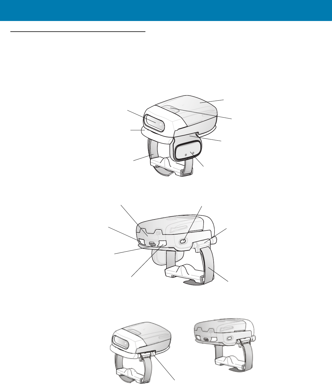
Cordless Configuration Features
Figure 1 RS507 Cordless Configuration Features
Imager Window
Battery
Battery Release Latch
Finger Strap
Scan Trigger
Strap Buckle
Beeper
Restore Key
Left Scan LED
Finger Strap
Right Scan LED
Comfort Pad
Trigger Swivel Assembly
Asset Control Label
Triggerless Strap Holder
Triggered Configuration
Triggerless Configuration
11 / 16 / 2017 REVIEW ONLY
REVIEW ONLY - REVIEW ONLY - REVIEW ONLY
Getting Started
18
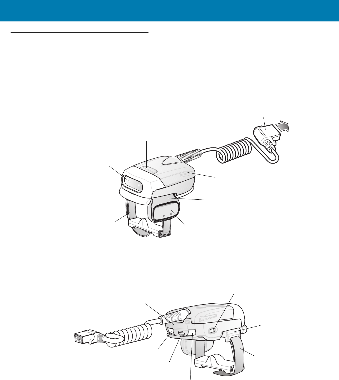
Corded Configuration Features
Figure 2 RS507 Corded Configuration Features
Release Latch
Imager Window
Finger Strap Scan Trigger
Comfort Pad
Corded Adapter
Strap Buckle
Beeper
Restore Key
Left Scan LED Finger Strap
Right Scan LED
Trigger Swivel Assembly
Interface Cable Connector to WT4090
Asset Control Label
11 / 16 / 2017 REVIEW ONLY
REVIEW ONLY - REVIEW ONLY - REVIEW ONLY
Getting Started
19
Trigger Swivel Assembly - Change Trigger Position
The Imager is worn on the index and middle fingers, and triggered with the thumb. The Trigger Swivel Assembly of
the Imager rotates to provide left-hand or right-hand use.
To change the position of the Trigger:
1. From the bottom of Imager, hold and pull the Comfort Pad off the Imager.
Figure 3 Change Trigger Position - Removal of Finger Strap and Comfort Pad
2. Determine whether the Imager is used on the right or left hand and rotate the Trigger Swivel Assembly.
Figure 4 Change Trigger Swivel Assembly Position
3. Rotate the Trigger Swivel Assembly so that the Scan Trigger is positioned next to the thumb when the Imager
is placed on the index and middle fingers.
4. Position the Comfort Pad onto the Imager.
5. Press the Comfort Pad onto the Imager. When properly installed, the Comfort Pad locks into place.
6. Insert the Finger Strap into the Strap Buckle.
NOTE:When removing the Comfort Pad off the Imager, It is not necessary to remove the Finger Strap
from the Trigger Swivel Assembly.
CAUTION:The Trigger Swivel Assembly only rotates 180° around the front of the scan assembly. Do not
rotate the Trigger Swivel Assembly past the designed stops.
Finger Strap
Strap Buckle
Comfort Pad
Trigger
Swivel
Assembly
Trigger Swivel Assembly
Scan Trigger
11 / 16 / 2017 REVIEW ONLY
REVIEW ONLY - REVIEW ONLY - REVIEW ONLY
Getting Started
20
Getting Started - Cordless Configuration
Charge the Battery
Before using the Imager, charge the battery. The SAC5070 8-Bay Battery Charger supports both standard and
extended capacity batteries.
To charge the Imager battery, refer to the SAC5070 8-Bay Battery Charger Quick Reference Guide, p/n
72-115989-01 available at: www.zebra.com/support and search for 'SAC5070'.
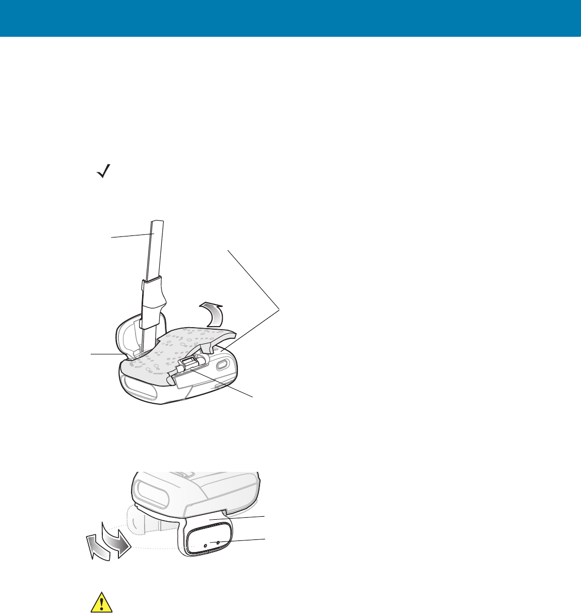
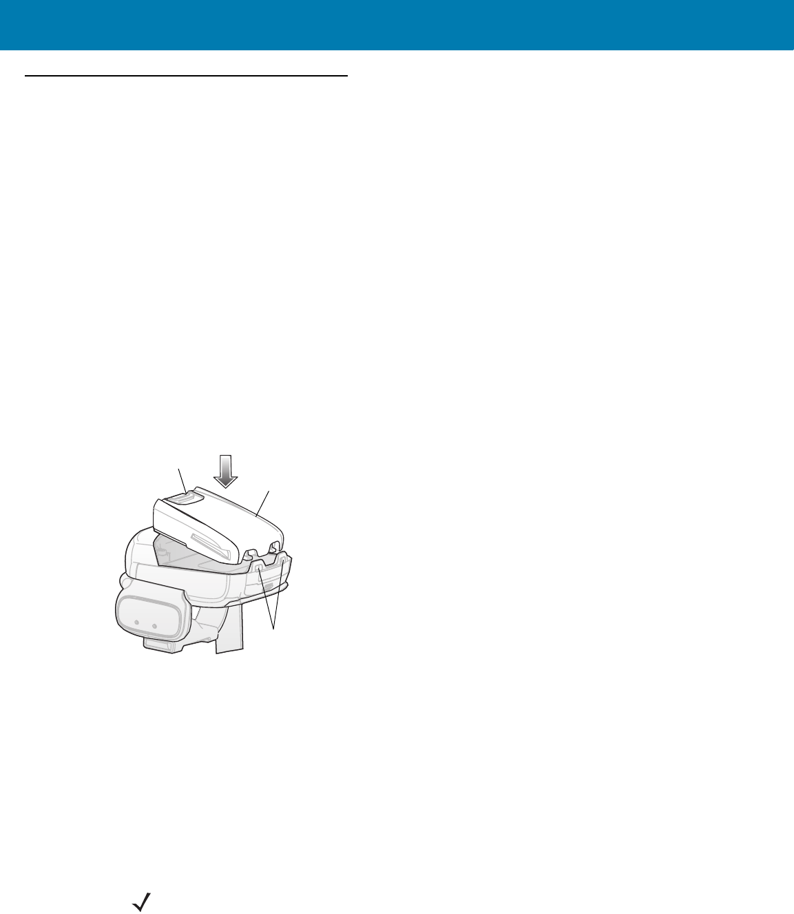
Install the Battery
1. Align the battery on top of the Imager.
2. Push the battery all the way into the Locking Slots of the Imager.
3. Firmly press the battery into the Imager until a “click” is heard ensuring the Battery Release Latch is fully
engaged with the Imager.
Figure 5 Install the Battery
Remove the Battery
1. Hold the Imager in one hand.
2. Press the Battery Release Latch.
3. Pull up the battery to release it from the Locking Slots of the Imager.
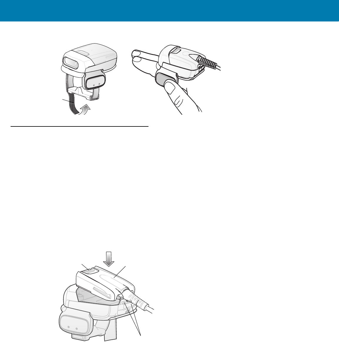
Wearing the Imager
1. Slide the Imager onto the index and middle fingers with the Scan Trigger next to the thumb.
2. Tighten the Finger Strap.
Locking Slots
Battery
Battery Release Latch
NOTE:When using the Imager for the first time, press and release the Scan Trigger to enable the
manual triggering mode (this operation disables the default auto triggering mode).
11 / 16 / 2017 REVIEW ONLY
REVIEW ONLY - REVIEW ONLY - REVIEW ONLY
Getting Started
21
Figure 6 Wearing the Imager - Cordless Adapter
Getting Started - Corded Configuration
In order to start using the Imager you must install the Corded Adapter.
Connect the Corded Adapter
To connect the Corded Adapter:
1. Align the Corded Adapter on top of the Imager.
2. Support the bottom side of the Imager and push the Corded Adapter all the way into the Locking Slots of the
Imager.
3. Firmly press the Corded Adapter into the Imager until a click is heard ensuring the Adapter Release Latch is
fully engaged with the Imager.
Figure 7 Connect Corded Adapter
Remove the Corded Adapter
To remove the Corded Adapter:
1. Hold the Imager in one hand.
2. Press the Adapter Release Latch.
3. Pull up the Corded Adapter to release it from the Locking Slots of the Imager.
Finger Strap
Locking Slots
Adapter Release Latch Corded Adapter
11 / 16 / 2017 REVIEW ONLY
REVIEW ONLY - REVIEW ONLY - REVIEW ONLY
Getting Started
22
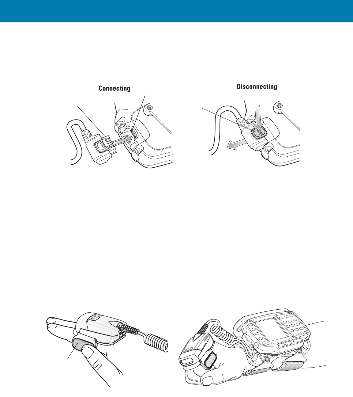
Connect to a WT4090 Wearable Terminal
The Imager connects to the Wearable Terminal and mounts on the fingers.
Figure 8 Connecting and Disconnecting to a Wearable Terminal
To connect the Imager to the terminal:
1. On the terminal, remove the cover from the WT4090 Interface Connector.
2. Connect the Interface Cable Connector of the Imager to the WT4090 Interface Connector.
To disconnect the Imager from the terminal:
1. Press the Disconnect Button on the Interface Cable Connector.
2. Pull the Interface Cable Connector out of the WT4090 Interface Connector.
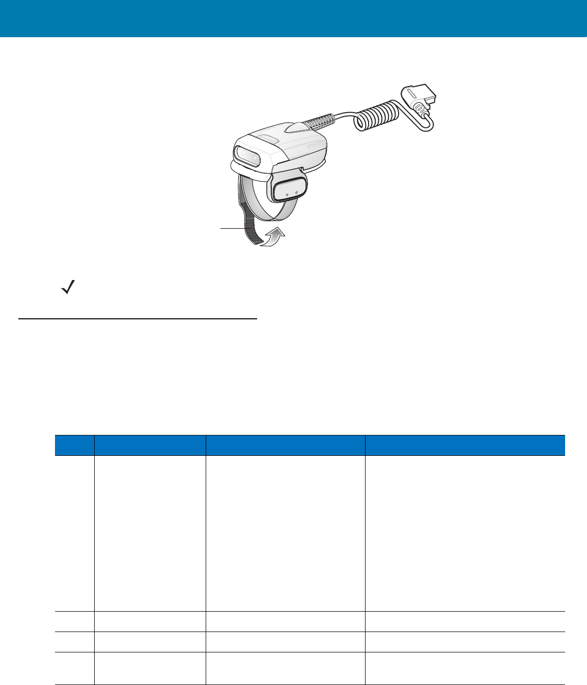
Wearing the Imager
To wear the Imager:
1. Slide the Imager onto the index and middle fingers with the Scan Trigger next to the thumb (see Figure 9).
Figure 9 Wear the Imager - Corded Adapter
2. Tighten the Finger Strap.
Interface Cable Connector 1
2
WT4090 Interface Connector
Disconnect
Button
Scan Trigger
11 / 16 / 2017 REVIEW ONLY
REVIEW ONLY - REVIEW ONLY - REVIEW ONLY
Getting Started
23
Figure 10 Wear the Corded Adapter Imager - Finger Strap
Status Indications
The Imager has two Scan LEDs that provide identical indications. The Imager is also equipped with a beeper that
issues different beep sequences and patterns to indicate status.
Table 2 defines the LED and beep sequences indications that occur during normal operation and bar code
scanning.
4t×Q
Finger Strap
NOTE:When using the Imager for the first time, press and release the Scan Trigger to enable the manual
triggering mode (this operation disables the default auto triggering mode).
Table 2 Status Indications
No. LED Beep Indication Description
1. None High/low Bluetooth communication is disconnected
due to:
•host device is powered off.
•host device Bluetooth is off.
•Bluetooth un-pair bar code
scanned by the RS507.
•Bluetooth Disconnect bar code
scanned by the RS507.
•RS507 is out of Bluetooth range
with the host device.
2. Short green flashes None Attempting to connect over Bluetooth.
3. None Low/high Imager is connected over Bluetooth.
4. None High/low/high/low Properly decoded scan of Bluetooth
pairing bar code.
11 / 16 / 2017 REVIEW ONLY
REVIEW ONLY - REVIEW ONLY - REVIEW ONLY

Getting Started
24
Imager Standby Mode
To save battery power, the Imager goes into Standby when not active.
The Image resumes functionality when:
•Bluetooth data is received from the mobile computer (in cordless configuration)
•Scan trigger is pressed
•Restore key is pressed
•Motion is detected (in cordless configuration)
•Incoming data from mobile computer is sensed (in corded configuration).
Bluetooth Connection
Establish Bluetooth Connection
To establish Bluetooth connection with a mobile computer:
1. Ensure that the Imager is within a range of 10 meters (30 feet) from the mobile computer.
2. Install the battery in the Imager.
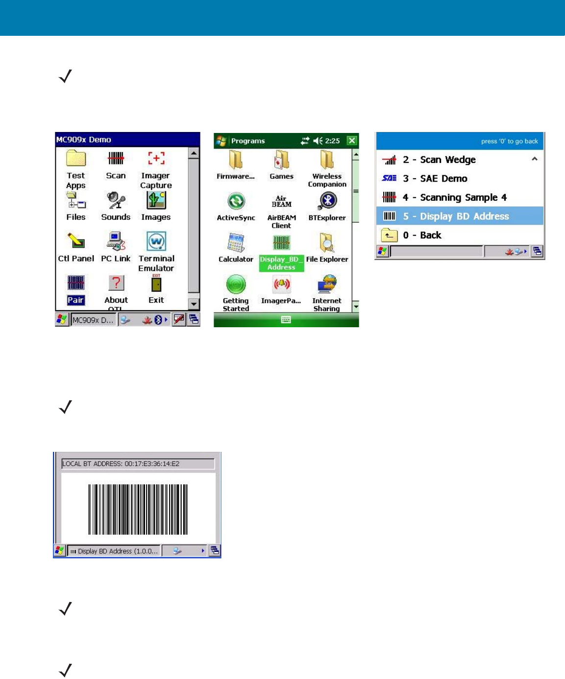
3. Launch the Bluetooth Device (BD) address application (see Figure 11) from the mobile computer. Most BD
Address applications display a pairing bar code image on the screen of the mobile computer.
5. None Long low/ long high/ Bluetooth connection attempt failed.
If there is no acknowledgment from the
host device.
Example: Bluetooth on the host device is
off.
6. None Long low/ long high/ Long low/
long high/
Bluetooth connection attempt is rejected.
When the RS507 tries to connect to the
host and the host rejects the connection.
Example: There is already a successful
Bluetooth connection in the host device
and it unable to create a new connection.
7. One green flash High Proper scanning indication.
8. None 4 long beeps No Bluetooth communication after
re-connection failure.
9. Red flash 2 short beeps every 15 seconds Low battery.
10. Long red flash
followed by a green
flash
High/low High/low Clean Boot was performed successfully.
Table 2 Status Indications
NOTE:When the Imager is connected by corded configuration, only “Proper scanning indication” and “Clean
Boot was perform successfully” status events are indicated.
11 / 16 / 2017 REVIEW ONLY
REVIEW ONLY - REVIEW ONLY - REVIEW ONLY
Getting Started
25
Figure 11 Icon of Bluetooth Device (BD) Address Application
4. Scan the pairing bar code on the mobile computer screen (see Figure 12) or a provided pairing label. When
scanning, the Imager emits one string of high/low/high/low beeps.
Figure 12 Pairing Bar Code Example as Shown on the Mobile Computer Screen
5. The Scan LED starts flashing green indicating that the Imager is attempting to establish connection with a
mobile computer.
6. When connection is established, the Scan LED turns off and the Imager emits one string of low/high beeps.
The Imager is connected and ready for scanning.
NOTE:To find the BD address application tap the Start button and select Programs > Display_BD_Address or Start
> Programs > BT Information and then tap the Generate Local BD Address Barcode button to display the BD
address bar code.
Bluetooth Device (BD) address icon on
Windows Mobile Programs screen
Bluetooth Device (BD) address icon
on WT4090 Application screen
Bluetooth Device (BD) address icon
on MC909X Demo screen
NOTE:To create printed pairing bar code label, refer to Pairing Bar Code Format on page 26.
NOTE:If the Imager default PIN code is required for establishing connection, enter the following code: "12345".
You may also need to set the authentication and encryption to Enabled.
NOTE:When replacing the Imager battery, the Imager memory retains the pairing information of the last paired
mobile computer.
11 / 16 / 2017 REVIEW ONLY
REVIEW ONLY - REVIEW ONLY - REVIEW ONLY

Getting Started
26
Restore Lost Bluetooth Connection
The Imager maintains Bluetooth communication with a mobile computer within a range of 10 meters (30 feet).
When the Imager fails to establish connection or connection is lost during operation, the Imager emits one string of
high/low beeps.
To reestablish the Bluetooth connection with a mobile computer:
1. Ensure that the Imager is within a range of 10 meters (30 feet) from the mobile computer.
2. Ensure that the mobile computer is on and “awake” (not in Suspend mode).
3. The Imager automatically attempts reconnecting to the mobile computer for 30 seconds (Scan LED flashes
green). If automatic re-connection fails, verify that the Imager is within Bluetooth range and briefly press the
Restore Key on the Imager to reconnect.
4. The Scan LED starts flashing green indicating that the Imager is attempting to establish connection with a
mobile computer. The Scan LED turns off and the Imager emits one string of low/high beeps indicating that the
Imager is connected and ready for scanning.
Remove Bluetooth Connection
Remove Bluetooth connection to allow the Imager to connect to another mobile computer or to enable the a mobile
computer to accept the connection from another Imager.
To remove Bluetooth connection:
1. Scan an un-pairing bar code for disconnecting the Imager from the mobile computer.
Figure 13 Un-pairing Bar Code
2. The Imager emits one string of high/low beeps indicating that Bluetooth communication with the mobile
computer is disconnected.
Pairing Bar Code Format
In order to pair the Imager with a mobile computer over Bluetooth, a pairing bar code must be created. You can use
the Display_BD_Address application on the mobile computer, or create and print a pairing bar code label. To
create a pairing bar code label, the Bluetooth address of the mobile computer should be available (refer to the
mobile computer user guide).
Pairing bar codes are Code 128 or Data Matrix symbologies formatted as follows:
<Fun3>Bxxxxxxxxxxxx
Where xxxxxxxxxxxx represents the 12-character Bluetooth address.
NOTE:You can also reconnect by scanning a pairing bar code from the mobile computer screen or provided
label. When scanning, the Imager emits one string of high/low/high/low beeps.
NOTE:Removing Bluetooth connection is only required if the Imager is configured to auto-connect upon
power-up (permanent pairing is enabled) and has to be paired with a different mobile computer.
11 / 16 / 2017 REVIEW ONLY
REVIEW ONLY - REVIEW ONLY - REVIEW ONLY
Getting Started
27
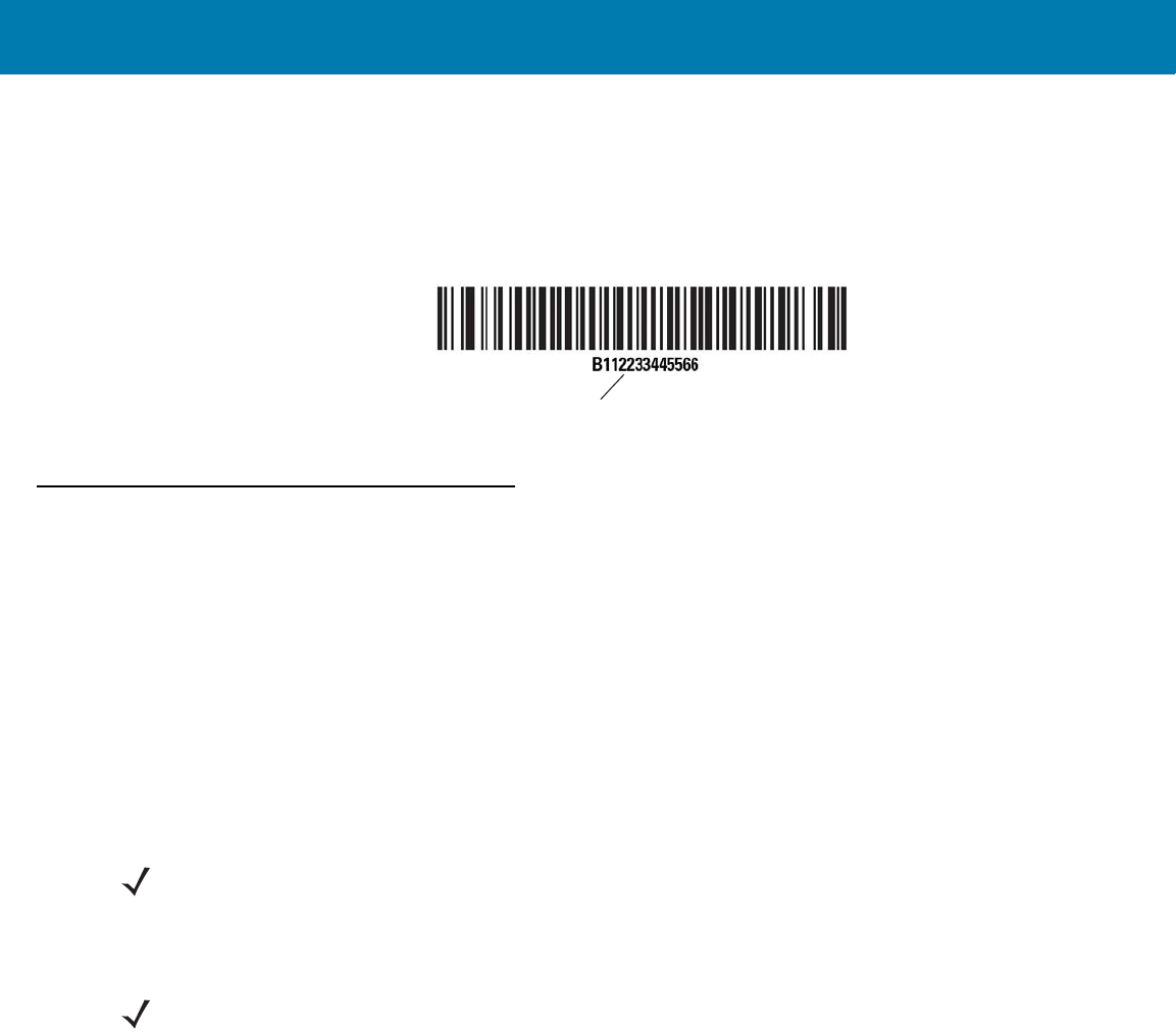
Pairing Bar Code Example
If the mobile computer to which the Imager connects has a Bluetooth address of 11:22:33:44:55:66, then the
pairing bar code is:
Figure 14 Creating a Pairing Bluetooth Bar Code
Scan
The Imager uses digital camera technology to take an image of a bar code and software decoding algorithms are
executed to extract the bar code data from the image.
Scan Triggering Modes
Manual Triggering (Triggered models only)
1. Launch a scanning software application on the mobile computer.
2. Position the Imager approximately 22.8 cm (9 inches) from a bar code and press the Scan Trigger. Position the
cross hair laser beam to cover the bar code. The Imager takes a digital picture (image) of the bar code and
stores it in memory for decoding.
3. One green flash of the LEDs is given and a high beep sounds to indicate that the bar code was properly
decoded.
Auto-triggering (Triggerless models only)
The Imager is provided with auto-triggering capability. In auto-triggering mode, both motion and proximity sensors
are used to trigger the Imager when the user intends to scan a bar code.
With auto-triggering activated, the Imager automatically scans when motion stops and a bar code is placed within
the depth of field of the Imager. The Imager scans the bar code and turns off to conserve power.
To scan a bar code in auto-triggering mode:
1. Position the Imager approximately 22.8 cm (9 inches) from a bar code.
2. Aim at the bar code.
3. The Imager takes a picture (image) of the bar code and stores it in memory for decoding.
Paring Bar Code Content: <Fnc 3> ‘B’ + Bluetooth Address
NOTE:After battery is inserted or a corded adaptor is connected (on both sides), the first trigger press disables the
auto triggering mode.
NOTE:In some configurations proper decoding of a bar code is indicated by the software application running on
the mobile computer.
11 / 16 / 2017 REVIEW ONLY
REVIEW ONLY - REVIEW ONLY - REVIEW ONLY
Getting Started
28
4. One green flash of the Scan LEDs and a high beep indicates that a bar code was properly decoded.
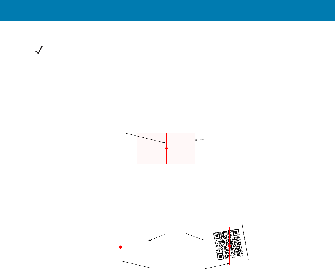
Aiming the Imager
The aiming pattern of the Imager is a cross hair laser beam with bright center dot (see Figure 15). The virtual
rectangle made by the cross hair reflects the field of view of the Imager. The aiming pattern is used to position the
bar code within the field of view.
Figure 15 Cross Hair Laser Beam
Enter the symbol in any orientation within the virtual rectangle made by the cross hair laser beam, making use of its
omnidirectional reading capability within the entire field of view.
Figure 16 Symbol Scan Orientation
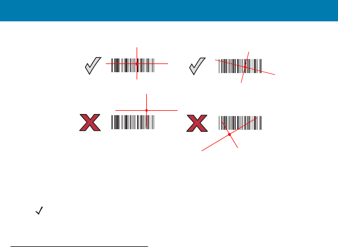
The Imager can also read a bar code presented within the aiming pattern but not centered (see the top bar codes
on Figure 17). The bar codes marked with X in Figure 17, however, show bar code aiming that may result in no
decode.
When using the application on your mobile computer in “Pick List” mode, the Bright Center Dot can be positioned
anywhere on the symbol (see Figure 15).The top examples in Figure 17 show acceptable aiming options, while the
bottom examples can not be decoded.
NOTE:In some applications, proper detection of a bar code is indicated by a software application running on
the mobile computer.
Virtual rectangle made by the cross hair laser beam
Cross hair laser beam
2D Bar Code
1D Bar Code
Symbol
Aiming pattern Pattern
@1234@
11 / 16 / 2017 REVIEW ONLY
REVIEW ONLY - REVIEW ONLY - REVIEW ONLY
Getting Started
29
Figure 17 Acceptable Aiming Options
The aiming pattern is smaller when the Imager is closer to the symbol and larger when it is farther from the symbol.
Scan symbols with smaller bars or elements (mil size) closer to the Imager and those with larger bars or elements
(mil size) farther from the Imager.
1. Hold the Imager between two and eleven inches from the bar code (depending on the bar code density).
2. Press the Scan trigger. The aiming pattern illuminates red indicating that the laser is on. One green flash of the
Scan LED and a high beep indicates that a bar code was properly decoded.
Customize the Imager
Changing from Triggered to Triggerless Configuration
To change from Triggered to Triggerless configuration:
1. Remove the Comfort Pad (see Comfort Pad Replacement on page 39).
2. Remove the Trigger Swivel Assembly (see Trigger Swivel Assembly Replacement on page 40).
3. Install the Triggerless Strap Holder (see Triggerless Strap Holder Replacement on page 41).
4. Install the Comfort Pad (see Comfort Pad Replacement on page 39).
5. Perform a cold boot (see Cold Boot on page 30).
Changing Triggerless to Triggered Configuration
To change from Triggerless to Triggered configuration:
1. Remove the Comfort Pad (see Comfort Pad Replacement on page 39).
2. Remove the Triggerless Strap Holder (see Triggerless Strap Holder Replacement on page 41).
3. Install the Trigger Swivel Assembly (see Trigger Swivel Assembly Replacement on page 40).
4. Install the Comfort Pad (see Comfort Pad Replacement on page 39).
5. Perform a cold boot (see Cold Boot on page 30).
012345
012345
012345
012345
NOTE:When a symbol is under transparent plastic or on a mobile computer screen, it is recommended to use a
tilt (pitch) or skew scan angle to minimize reflection.
11 / 16 / 2017 REVIEW ONLY
REVIEW ONLY - REVIEW ONLY - REVIEW ONLY

Getting Started
30
6. Press and release the Scan Trigger to enable the manual triggering mode (this operation disables the default
Triggerless mode).
Resetting the Imager
If the Imager stops responding to input, reset it. There are three reset functions, warm boot, cold boot and clean
boot. Perform a warm boot first. If the Imager still does not respond, perform a cold boot. Perform clean boot to
restore the Imager to its factory default configuration.
Warm Boot
To perform warm boot, press and hold the Restore Key for more than six seconds.
Cold Boot
Cold boot restores the Imager’s operation by resetting its software. To perform cold boot, remove and re-insert the
battery into the Imager. When using a corded Imager model with WT4090, remove and reconnect the interface
cable that connects between the Imager and the WT4090.
Clean Boot
Clean Boot restores the Imager to its factory default configuration.
To perform clean boot:
1. Remove battery or disconnect the Corded Adapter.
2. Press and hold the Restore Key.
3. Insert the battery or Corded Adapter into the Imager.
4. Continue to press and hold the Restore Key for about five seconds until a chirp is heard and the Scan LEDs
flash green. The Imager is now in its factory default configuration.
NOTE:The factory default configuration is set in the factory or the service center. These parameters are unique
for each Imager and cannot be changed. The Factory default configuration includes: Imager serial number,
Bluetooth Device (BD) address, model number, production date and proximity calibration.
11 / 16 / 2017 REVIEW ONLY
REVIEW ONLY - REVIEW ONLY - REVIEW ONLY

31
SAC5070 8-Bay Battery
Charger
Introduction
The SAC5070 8-Bay Battery Charger is an accessory for the RS507 Hands-free Imager and provides a quick way
to recharge the Lithium-ion battery that provide power for the RS507 Hands-Free Imager. One charger can hold up
to eight batteries at a time.
The 8-Bay Battery Charger supports both standard and extended capacity batteries. The Charger may only be
used indoors.
Unpacking the Charger
After opening the shipping box, inspect the contents. You should have received the following:
* For AC line cord, contact the Zebra representative in your country.
Inspect the equipment for damage. If you are missing any equipment or if you find any damaged equipment,
contact Zebra Support immediately.
Model Description 8-Bay Battery
Charger Power supply AC Line
Cord Quick Start Guide
SAC5070-800C
R
USA model x x x x
SAC5070-801C
R
International
model
xx* x
11 / 16 / 2017 REVIEW ONLY
REVIEW ONLY - REVIEW ONLY - REVIEW ONLY
SAC5070 8-Bay Battery Charger
32
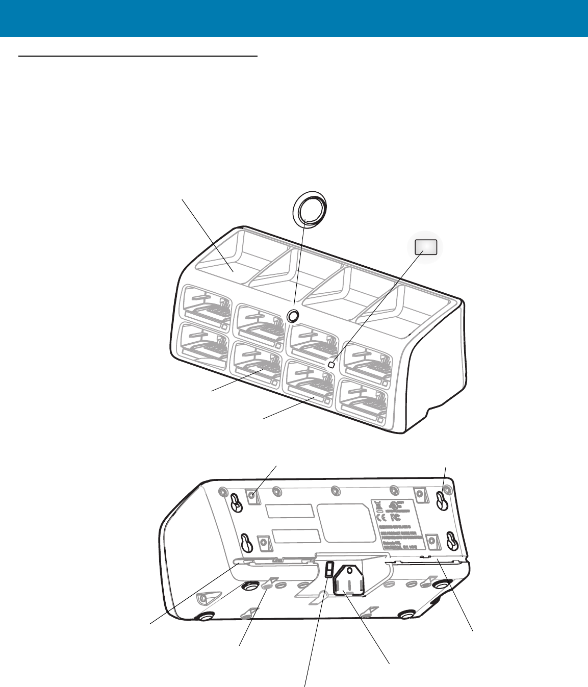
Parts of the Charger
Figure 18 Parts of the Charger
Batteries Age Test Button
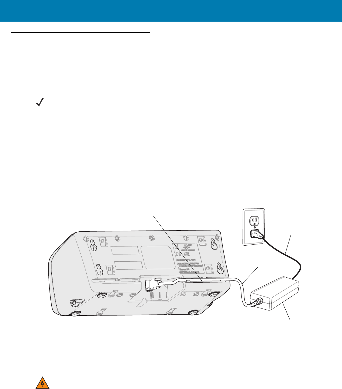
Power Supply Connector
Charge Status LED
Charging Bay
RS507 Imager Rest Compartment
Power Supply Cable Duct
Service Port Door
(Do not open - for service use only)
Wall Mount Hole (X4)
Charger Front
Charger Back
Power Supply Cable Duct
Asset Control Label
M4 Screw Inserts (X4)
(Screws not Included)
M4 Screw Inserts (X4)
(Screws not Included)
11 / 16 / 2017 REVIEW ONLY
REVIEW ONLY - REVIEW ONLY - REVIEW ONLY
SAC5070 8-Bay Battery Charger
33
Installation
Tabletop / Shelf Set Up
To set the Charger on a tabletop or shelf:
1. Place the Charger and the Power Supply Unit on a tabletop or shelf.
2. Connect the Power Supply Cable to the power connector on the back of the Charger.
3. Use the Power Supply Cable Duct, on the back of the Charger, to route the Power Supply Cable to the left or
right side of the Charger.
4. Connect the AC plug of the AC Power Cord to a standard electrical outlet.
Figure 19 Charger Installation
Wall Mount
To mount the Charger on a wall:
1. Mark the screw location on the wall.
NOTE:When required, use the screw inserts at the back and base to secure the Charger to the tabletop or shelf
surface.
AC Power Cord
Power Supply Cable
Power Supply Unit
100-240 VAC, 50-60 Hz Outlet
Power Supply Cable Duct
WARNING:For safe mounting, it is essential to use wall anchors appropriate to the wall type (i.e. plaster, drywall,
concrete, etc.). Mount to wood studs whenever possible.
11 / 16 / 2017 REVIEW ONLY
REVIEW ONLY - REVIEW ONLY - REVIEW ONLY
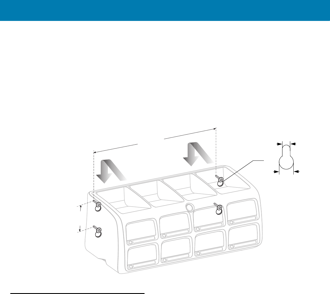
SAC5070 8-Bay Battery Charger
34
2. Use four screws to mount the Charger to a wall. Be sure to use additional wall mounting hardware, as needed,
for safe mounting according to the wall type.
3. Connect the power supply cable to the power connector on the back of the Charger (see Figure 20).
4. Use the Power Supply Cable Duct, on the back of the Charger, to route the Power Supply Cable to the left or
right side of the Charger.
5. Place the Power Supply Unit on a shelf or tabletop.
6. Connect the AC plug of the AC Power Cord to a standard electrical outlet.
Figure 20 Wall Mounting of Charger
Inserting the Imager Battery in the Charger
The Charger supports both standard and extended capacity batteries.
220 mm (8.6 inches)
38 mm (1.5 inches)
10 mm
(0.39 inches)
5 mm
(0.19 inches)
11 / 16 / 2017 REVIEW ONLY
REVIEW ONLY - REVIEW ONLY - REVIEW ONLY
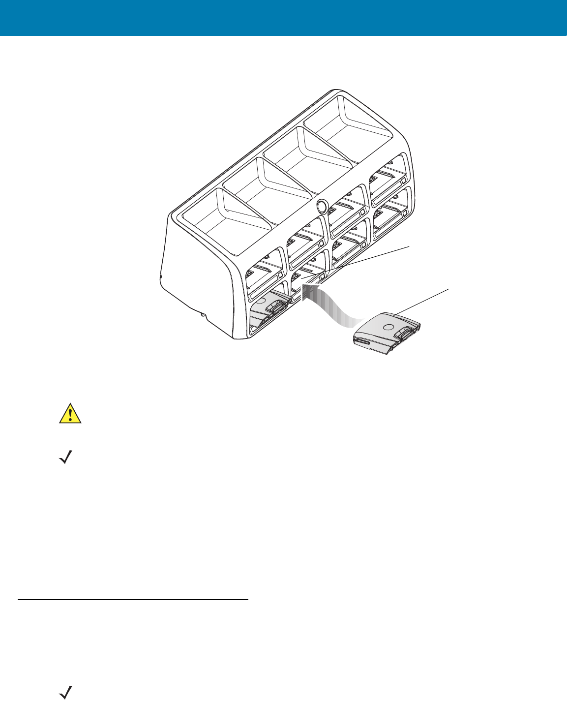
SAC5070 8-Bay Battery Charger
35
Figure 21 Inserting the Imager Battery into the Charger
Charge the Battery
To charge the battery(s):
1. Insert the battery(s) into the 8-Bay Battery Charger so that the contacts of the battery are first to enter, facing
down, gently. Do not use excessive force.
2. The 8-Bay Battery Charger starts to charge automatically. On each bay, the flashing amber Charge Status
LED (see Figure 18) indicates the charge status.
A full charge of a depleted battery takes up to four hours. The Charge Status LED lights solid amber when the
battery is fully charged.
Battery Age Test
The battery age test checks the battery capacity when fully charged. A worn-out battery is considered to have less
than 80% of its nominal capacity. The battery test is simultaneously performed for all batteries inserted into the
charger. It is recommended to perform battery age testing once a month. The age test may take up to 16 hours.
Standard Battery
Charger Bay
CAUTION:Only Lithium-ion batteries that have been designed for use with the RS507 Hands-free Imager can be
recharged by the Charger. Do not attempt to recharge other types of rechargeable batteries or any
type of batteries. Doing so could destroy those batteries and damage the Charger.
NOTE:Batteries should be charged within the 0°C (+32°F) and +40°C (+104°F) ambient temperature range.
NOTE:A battery removed during test and re-inserted is excluded from the test but continues normal charging.
11 / 16 / 2017 REVIEW ONLY
REVIEW ONLY - REVIEW ONLY - REVIEW ONLY

SAC5070 8-Bay Battery Charger
36
To test the battery(s):
1. Insert one or more batteries into Charging Bay(s).
2. Press and hold the Test Button for approximately 3 seconds until the Charge Status LED of each active bay
flashes green.
3. Refer to the table below when the indication of the Charge Status LED changes.
Charge Status LED
The Charge Status LEDs show the charge status of each Charging Bay:
Table 3 Charge LED - Status Indications
LED Indication Status
Flashing amber Charging in progress.
Solid amber Charging is completed.
Flashing green Battery age testing in progress.
Flashing red/green Defective battery or error in charging; re-insert the battery into the bay.
Solid green Battery age test and charge are completed. Battery is good.
Solid red Battery age test and charge are completed. Battery capacity is marginal.
Flashing red Battery age test and charge are completed. Battery is worn out.
11 / 16 / 2017 REVIEW ONLY
REVIEW ONLY - REVIEW ONLY - REVIEW ONLY

37
Troubleshooting &
Maintenance
Introduction
This chapter provides suggested Imager and Charger troubleshooting and maintenance.
Troubleshooting
Imager
Table 4 Imager Troubleshooting
Problem Cause Solution
Laser aiming pattern
does not display when
pressing the Scan
Trigger.
Corded: Interface cable is not secure. Verify that the interface cable is properly
connected.
Cordless: Battery is not charged. Replace or charge battery.
Power is not applied to Imager. Corded: Verify that the mobile computer
has a fully charged battery installed.
Cordless: Replace or charge Imager
battery.
Scan application on the mobile
computer is not functioning.
Restart the scanning application on the
mobile computer.
Imager does not respond. Reset the Imager (See Resetting the
Imager on page 30).
11 / 16 / 2017 REVIEW ONLY
REVIEW ONLY - REVIEW ONLY - REVIEW ONLY

Troubleshooting & Maintenance
38
Charger
Imager does not decode
a bar code.
Bar code is unreadable. Verify that the bar code is not defective,
i.e., smudged or damaged.
Exit window is dirty. Clean exit window with a lens tissue.
Tissues for eyeglasses work well. Do not
use tissues coated with lotion (see
Cleaning the Imager on page 46).
Bar code symbology is not supported
or enabled.
See your system administrator.
Cordless: Bluetooth link is
disconnected.
Reestablish Bluetooth connection (See
Establish Bluetooth Connection on page
24).
Table 4 Imager Troubleshooting
Problem Cause Solution
NOTE:If after performing these checks the Imager still experiences problems, contact the distributor or call
Zebra Support. See <em_Emphasis>Service Information on page 14.
Table 5 Charger Troubleshooting
Problem Solution
The Power LED does not light Make sure the Power plug of the Power Supply Unit is plugged into a wall
outlet and the connector on the end of the Power Supply Cable is
plugged into the Charger’s power connector.
Plug the Power plug of the Power Supply Unit into another outlet.
Replace the Power Supply Unit.
Contact a service representative (see <em_Emphasis>Service
Information on page 14).
The battery takes too long to
recharge
Ensure that room/battery temperatures are within charging range
0 ºC to +40 ºC (+32 ºF to +104 ºF).
Clean the contacts on the battery (see Cleaning the Charger on page 47).
Try another battery to make sure the Charger functions properly. (If the
charge time is more than four hours the Charge Status LED flashes
red/green.)
Contact a service representative (see <em_Emphasis>Service
Information on page 14).
11 / 16 / 2017 REVIEW ONLY
REVIEW ONLY - REVIEW ONLY - REVIEW ONLY
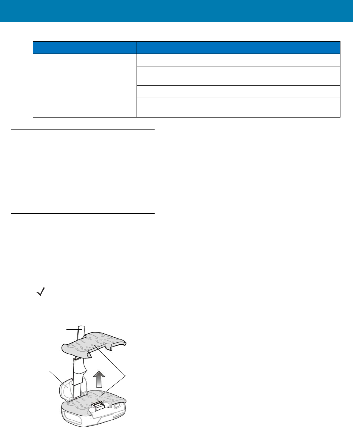
Troubleshooting & Maintenance
39
Maintenance
Cleaning the scan window is the basic maintenance required. A dirty window can affect scanning accuracy.
•Do not allow abrasive material to touch the window.
•Remove any dirt particles with a damp cloth.
•Wipe the window using a tissue moistened with ammonia/water.
•Do not spray water or other cleaning liquids directly into the window.
Maintaining the Imager
Comfort Pad Replacement
Removal
To remove the Comfort Pad: from the bottom of the Imager, hold and pull the Comfort Pad out of the Imager.
Figure 22 Removal of Comfort Pad
LED indication continuously
changes from red to green
Remove and re-insert the battery into the charging bay.
Check for dirt on battery charging contacts and/or charging bay contacts
(see Cleaning the Charger on page 47).
Replace battery with a new one.
Contact a service representative (see <em_Emphasis>Service
Information on page 14).
Table 5 Charger Troubleshooting
Problem Solution
NOTE: It is not necessary to remove the Finger Strap from the Trigger Swivel Assembly.
Comfort Pad
Finger Strap
Trigger Swivel
Assembly
11 / 16 / 2017 REVIEW ONLY
REVIEW ONLY - REVIEW ONLY - REVIEW ONLY
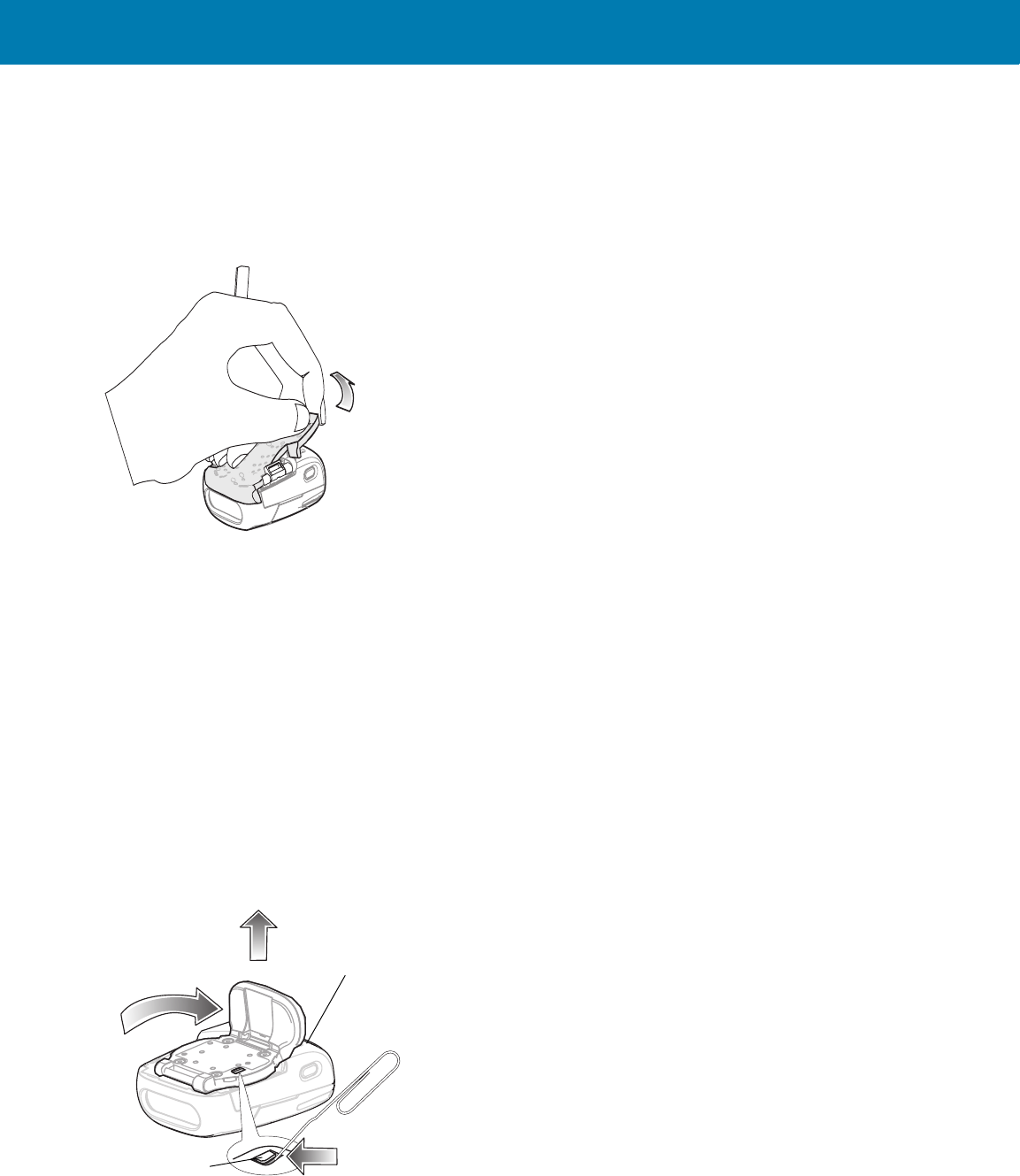
Troubleshooting & Maintenance
40
Installation
To install the Comfort Pad:
1. Position the Comfort Pad onto the Imager as shown.
Figure 23 Installation of Comfort Pad
2. Press the Comfort Pad onto the Imager. When properly installed, the Comfort Pad locks into place.
Trigger Swivel Assembly Replacement
Removal
To remove the Trigger Swivel Assembly:
1. Turn the Imager upside-down.
2. Remove the Comfort Pad.
3. Use a paper clip or similar object to press the Release Latch.
Figure 24 Removal of Trigger Swivel Assembly
4. Rotate the Trigger Swivel Assembly to align with the back of the Imager.
5. Lift the Trigger Swivel Assembly off the scan assembly.
2
1
3
Release Latch
Imager Back
11 / 16 / 2017 REVIEW ONLY
REVIEW ONLY - REVIEW ONLY - REVIEW ONLY
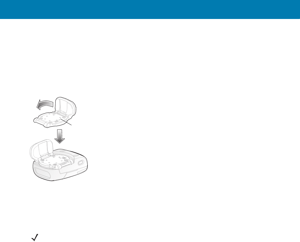
Troubleshooting & Maintenance
41
Installation
To install the Trigger Swivel Assembly:
1. Turn the Imager upside-down.
2. Position the Trigger Swivel Assembly to align with the back of the Imager.
3. Lower the Trigger Swivel Assembly onto the scan assembly.
Figure 25 Installation of Trigger Swivel Assembly
1. Rotate the Trigger Swivel Assembly 1/4 turn counterclockwise.
2. Press the Comfort Pad onto the Imager. When properly installed, the Comfort Pad locks into place.
Triggerless Strap Holder Replacement
Removal
To remove the Triggerless Strap Holder:
1. Turn the Imager upside-down.
2. Remove the Comfort Pad.
3. Use a paper clip or similar object to press the Release Latch.
1
Trigger Swivel Assembly
2
NOTE:The Triggerless Strap Holder should be installed when the Imager is intended to be used in Motion and
Proximity Initiated bar code read mode.
11 / 16 / 2017 REVIEW ONLY
REVIEW ONLY - REVIEW ONLY - REVIEW ONLY
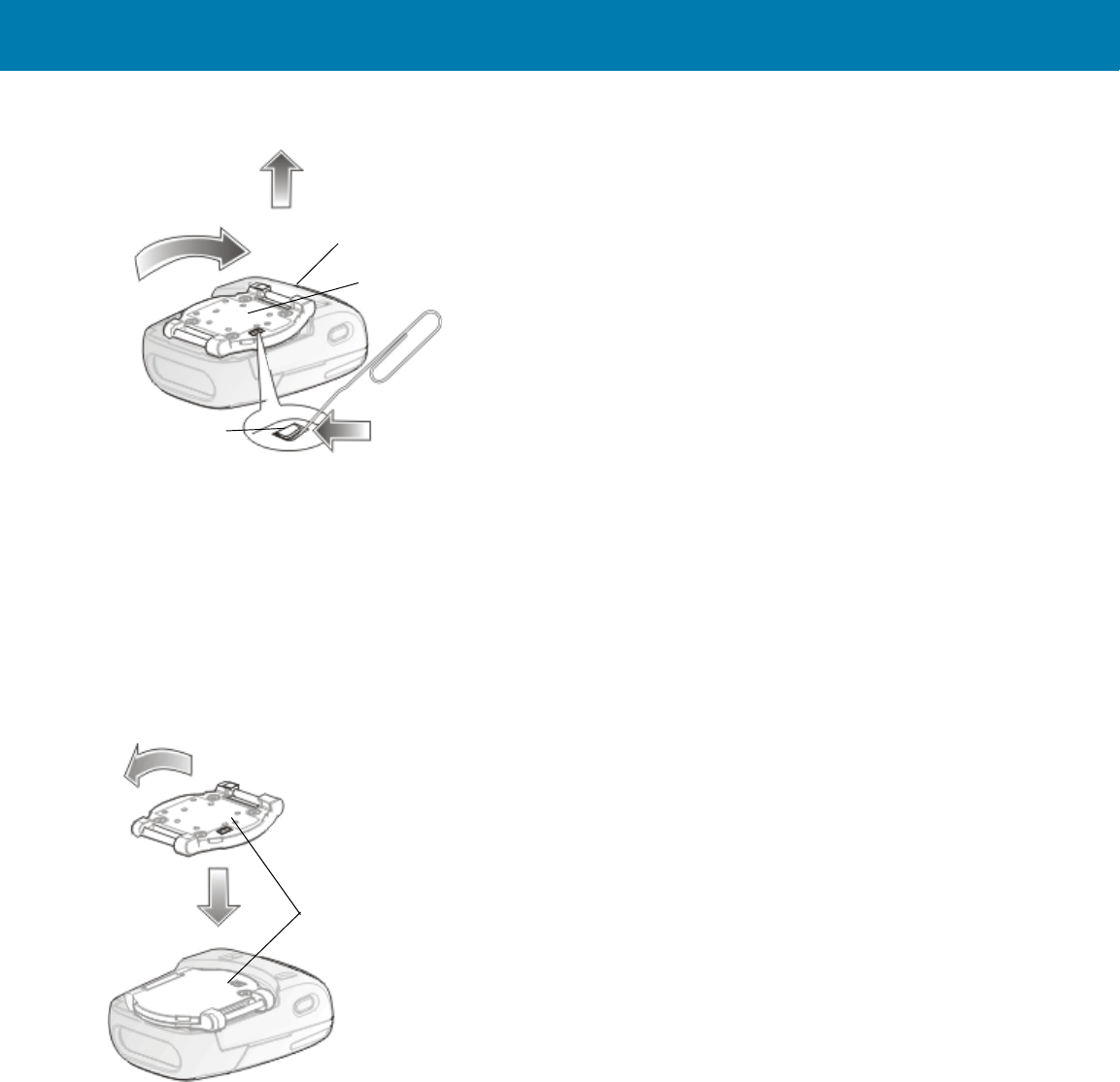
Troubleshooting & Maintenance
42
Figure 26 Removal of Triggerless Strap Holder
4. Rotate the Triggerless Strap Holder to align with the back of the Imager.
5. Lift the Triggerless Strap Holder off the Imager.
Installation
To install the Triggerless Strap Holder:
1. Position the Triggerless Strap Holder to align with the back of the Imager.
Figure 27 Turn the Imager upside-down.Installation of Triggerless Strap Holder
1. Lower the Triggerless Strap Holder onto the Imager.
2. Rotate Triggerless Strap Holder 1/4 turn counterclockwise.
Finger Strap Replacement (Trigger Swivel Assembly)
Removal
1. Remove the Finger Strap from the Strap Buckle.
2. Pull the Finger Strap out of the Trigger Swivel Assembly.
2
1
3
Release Latch
Imager Back
Triggerless Strap Holder
1
Triggerless Strap Holder
2
11 / 16 / 2017 REVIEW ONLY
REVIEW ONLY - REVIEW ONLY - REVIEW ONLY

Troubleshooting & Maintenance
43
Installation
1. Align a new Finger Strap with the Slots in the Trigger Swivel Assembly.
Figure 28 Finger Strap Replacement (Trigger Swivel Assembly)
2. Gently press the Strap Pins to engage with the Slots of the Trigger Swivel Assembly. The Strap Pins snap into
the slots.
3. Slip the Finger Strap through the Strap Buckle.
Strap Pins
Slots Strap Buckle
Finger Strap
Trigger Swivel Assembly
11 / 16 / 2017 REVIEW ONLY
REVIEW ONLY - REVIEW ONLY - REVIEW ONLY

Troubleshooting & Maintenance
44
Finger Strap Replacement (Triggerless Strap Holder)
Figure 29 Replacement of Finger Strap (Triggerless Strap Holder)
Removal
Remove the Finger Strap from the Strap Buckles.
Installation
Slip the Finger Strap through the Strap Buckles.
Strap Buckle Replacement
Figure 30 Strap Buckle Replacement
Removal
1. Remove the Trigger Swivel Assembly (see Trigger Swivel Assembly Replacement on page 40).
2. Press the Strap Buckle off the Trigger Swivel Assembly Pin.
Installation
1. Align the pin slot of Strap Buckle with the pin of the Trigger Swivel Assembly.
Strap Buckles
11 / 16 / 2017 REVIEW ONLY
REVIEW ONLY - REVIEW ONLY - REVIEW ONLY
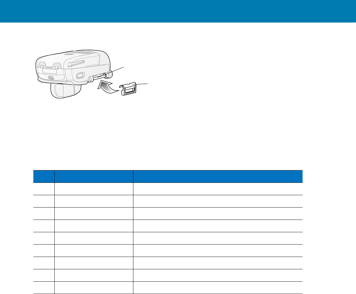
Troubleshooting & Maintenance
45
Figure 31 Strap Buckle Replacement
2. Gently press the pin slot of Strap Buckle to engage with the pin of the Trigger Swivel Assembly. The pin slot
snaps onto the pin.
3. Install the Trigger Swivel Assembly (see Trigger Swivel Assembly Replacement on page 40).
Field Replaceable Parts
Strap Buckle
Strap Buckle Pin
Table 6 Imager Field Replaceable Parts
No Part Description
1 KT-CLMPT-RS507-01R Trigger Swivel Assembly
2 KT-BKL-RS507-10R Set of 10 Strap Buckles
3 KT-CLMPN-RS507-01R Triggerless Strap Holder
4 KT-PAD-RS507-10R Set of 10 Comfort Pads
5 KT-STRPN-RS507-10R Set of 10 Triggerless Finger Strap with Finger Support
6 KT-STRPT-RS507-10R Set of 10 Trigger Finger Strap with Finger Support
7 KTBTRYRS50EAB00-01 Standard Battery
8 KTBTRYRS50EAB02-01 Extended Battery
9 ADPTRWT-RS507-R Corded Adapter
11 / 16 / 2017 REVIEW ONLY
REVIEW ONLY - REVIEW ONLY - REVIEW ONLY
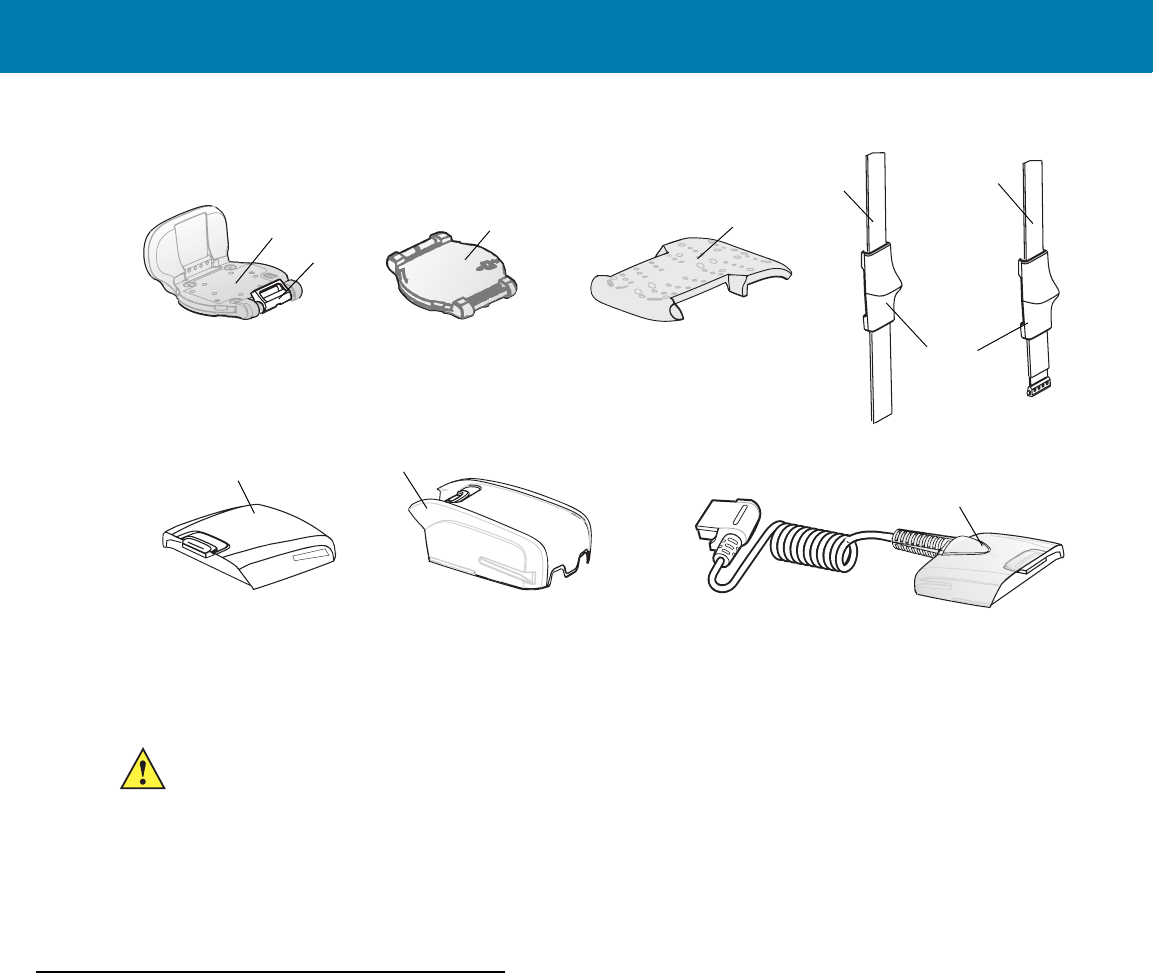
Troubleshooting & Maintenance
46
Figure 32 Imager Field Replaceable Parts
Cleaning the Imager
Wipe the exit window periodically with a lens tissue or other material suitable for cleaning eyeglasses.
The gold plated battery contacts do not tarnish or oxidize. No maintenance should be needed. If the contacts need
to be cleaned:
1. Wet the tip of a cotton swab with isopropyl alcohol and squeeze the excess alcohol from the swab.
2. Wipe the metal contacts with the damp swab.
Maintaining the Charger
The Charger is well constructed and durable; however, it is a precision electronic device and must be treated as
such.
Follow the procedures in this section to ensure reliable service.
Operating conditions for the Charger
The Charger is designed to operate in environments that are normally free of dust, dirt, and moisture. It can be
operated at temperatures between 0°C (+32°F) and +40°C (+104°F).
Handling the Charger
•Do not attempt to open the Charger. No user-serviceable parts are inside.
•Charge only Lithium-ion batteries that have been designed for use with the Imager. Do not attempt to
recharge other types of rechargeable batteries or any type of primary batteries.
1
2
34
56
78
9
Finger Support
CAUTION:Do not pour, spray, or spill any liquid on the Imager.
11 / 16 / 2017 REVIEW ONLY
REVIEW ONLY - REVIEW ONLY - REVIEW ONLY

Troubleshooting & Maintenance
47
•Do not place objects other than Imager batteries inside the Charger.
•Protect the Charger from excessive heat, cold, moisture, and harsh, dirty environments.
•Do not leave the Charger where moisture will condense on it.
Cleaning the Charger
The gold plated battery contacts do not tarnish or oxidize. No maintenance should be needed. If the contacts need
to be cleaned:
1. Remove power from the Charger.
2. Wet the tip of a cotton swab with isopropyl alcohol and squeeze the excess alcohol from the swab.
3. Wipe the metal contacts with the damp swab.
CAUTION:Do not pour, spray, or spill any liquid on the Charger.
11 / 16 / 2017 REVIEW ONLY
REVIEW ONLY - REVIEW ONLY - REVIEW ONLY

48
RS507 Update and
Configuration
Introduction
This chapter covers the following topics:
•Configuring the Imager
•Imager Motion and Proximity Configuration
•Debugging logger
•Firmware upgrade
Configuring the Imager
Introduction
The Imager is a modular product used in several hardware configurations. Such configurations may include corded
or cordless connection to a terminal / mobile computer with manual or automatic triggering.
The Imager is provided with a default software configuration set in the factory. This software configuration can be
optimized by the customer to meet their specific operational requirements. Therefore, before using the Imager, it is
essential that the Imager be properly configured to harness its extensive capabilities and gain maximum efficiency.
There are several ways to configure the Imager. The best way is to set the parameters for each application
allowing the required degrees of freedom. In some cases it is recommended to allow the user to select between the
various operational modes or use cases, each with its own set of parameters.
Zebra mobile computers using the EMDK may utilize the SCAN and/or RSM APIs to configure the operation of the
Imager. Zebra terminals that cannot use the EMDK, may configure some operations of the Imager by scanning
special configuration bar codes (see Miscellaneous Imager Options on page 70) as done with many of Zebra bar
code scanners.
A selection of most configured Imager parameters can be set with the Remote Scanner Management Sample
(RSMSample) application installed on all Zebra mobile computers supporting the Imager. Some of the Imager
parameters can also be set by the Control Panel application.
Once connected to a mobile computer, the application running on the mobile computer overrides the Imager
parameters previously set.
11 / 16 / 2017 REVIEW ONLY
REVIEW ONLY - REVIEW ONLY - REVIEW ONLY
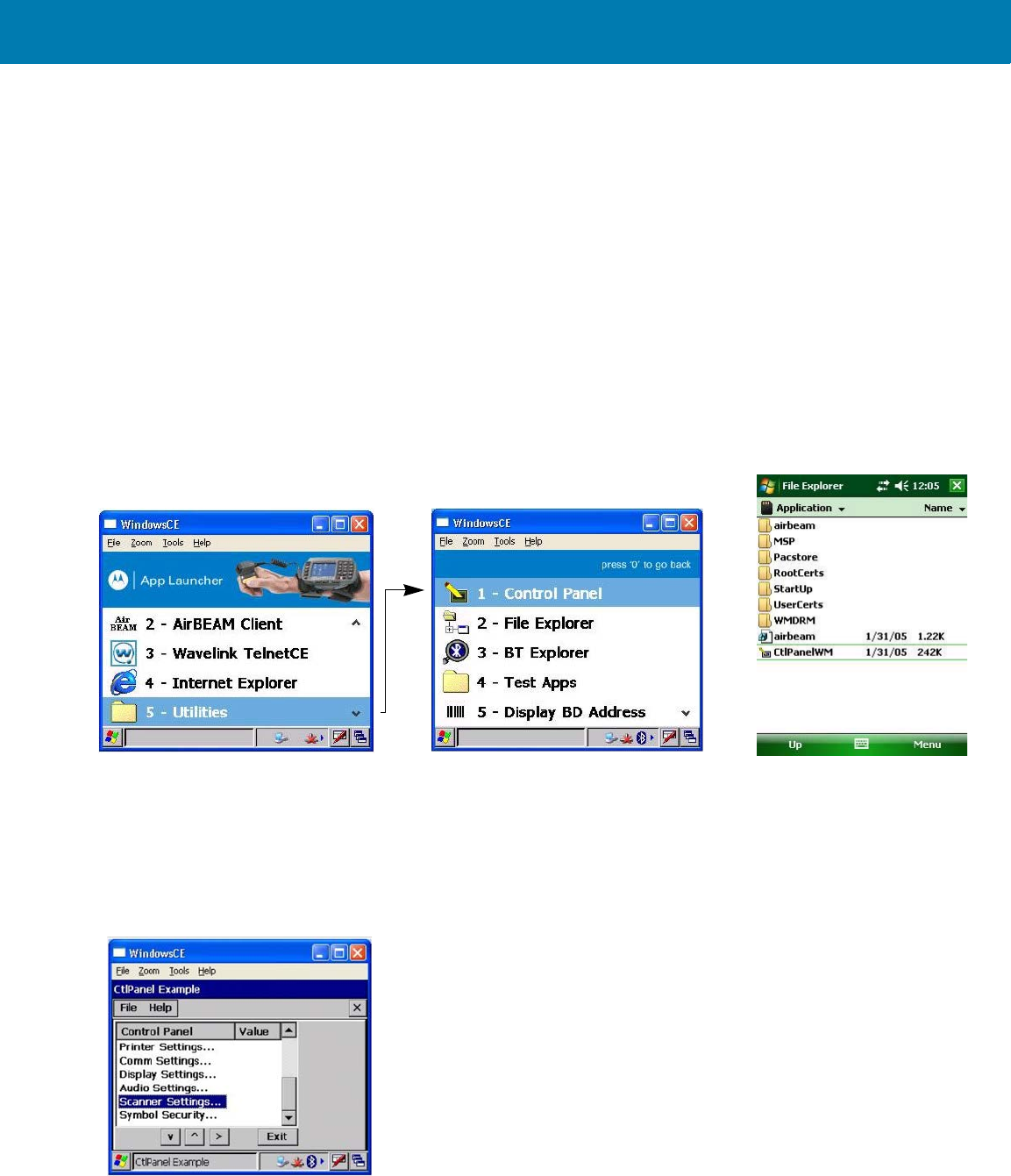
RS507 Update and Configuration
49
Control Panel Application
The Control Panel (CTLpanel) application can be used for configuring the Imager by changing its values. The
Control Panel application also enables one to retrieve and display the current setting of each value.
The Control Panel application together with the RSMsample application enable the user to configure the RS507.
Users with Mobile computer that do not have the Control Panel application installed can download the application
(CtlPanelWM.exe) and related documentation from the Support Central site at: http://www.zebra.com/support.
The following example describes how to read and configure new values of the Imager attributes.
To set new attribute values:
1. When using the WT4090, from the App Launcher screen, open the Utilities folder and start the Control Panel
application. When using a mobile computer with Windows Mobile, open the Application folder and start the
CtlPanelWM application.
Figure 33 Starting the Control Panel Application
2. Select Scanner Settings .....
Figure 34 Scanner Settings
WT4090 - Control Panel Application Windows Mobile -
Control Panel Application
11 / 16 / 2017 REVIEW ONLY
REVIEW ONLY - REVIEW ONLY - REVIEW ONLY
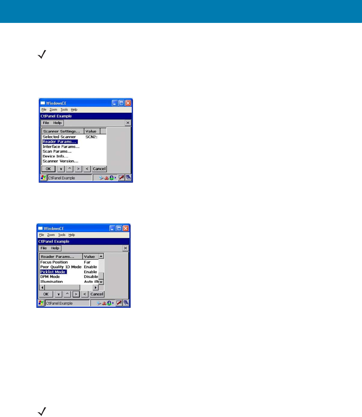
RS507 Update and Configuration
50
3. Use the > < keys to select scanner. Select SCN1 for corded Imager or SCN2 for cordless Imager (Bluetooth).
4. Select Reader Params…
Figure 35 Reader Params
5. Use the > < keys to change the Picklist Mode to Enable and press the OK button.
Figure 36 Picklist Mode
This setting is retained until cold boot is performed to the mobile computer or new setting is entered through
the Control Panel application.
6. Re-start your scan application and verify that Picklist Mode is enabled.
RSMSample Application
The Remote Scanner Management Sample (RSMSample) application is used for configuring the Imager by
changing its attribute values. The RSMSample application also enables one to retrieve and display the current
setting of each attribute. Users with mobile computer that do not have the RSMSample application installed can
download the application and related documentation from the Support Central site at: www.zebra.com/support.
The following example describes how to read and configure new values of the Imager attributes.
NOTE:Before you select
SCN2
make sure to pair and connect the Imager to the mobile computer.
NOTE:When the Imager is connected to a mobile computer, configuration by scanning bar codes is disabled. In
such case, the Imager configuration is performed by the application (e.g RSMSamplen) running on the mobile
computer. The new configuration overrides the previous configuration. The new configuration is saved in the
Imager memory after disconnecting the Imager from the mobile computer or terminating the application.
11 / 16 / 2017 REVIEW ONLY
REVIEW ONLY - REVIEW ONLY - REVIEW ONLY
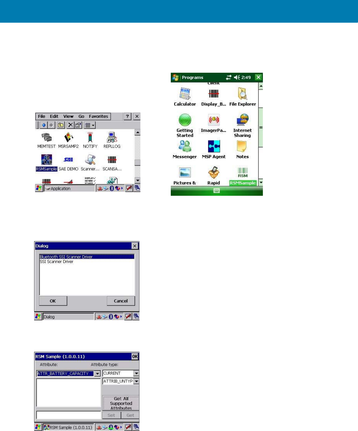
RS507 Update and Configuration
51
To set new attribute values:
1. From the mobile computer Application folder, run the RSMSample application.
Figure 37 Mobile Computer Application Folder - RSMSample Application Icon
2. From the Dialog window, select Bluetooth SSI Scanner Driver.
Figure 38 Dialog Window - Bluetooth SSI Scanner Driver
3. Press the Get All Supported Attributes button to display all supported attributes.
Figure 39 RSMSample Application - Get All Supported Attributes Button
Windows Mobile - RSMSample Application
WT4090 - RSMSample Application
11 / 16 / 2017 REVIEW ONLY
REVIEW ONLY - REVIEW ONLY - REVIEW ONLY
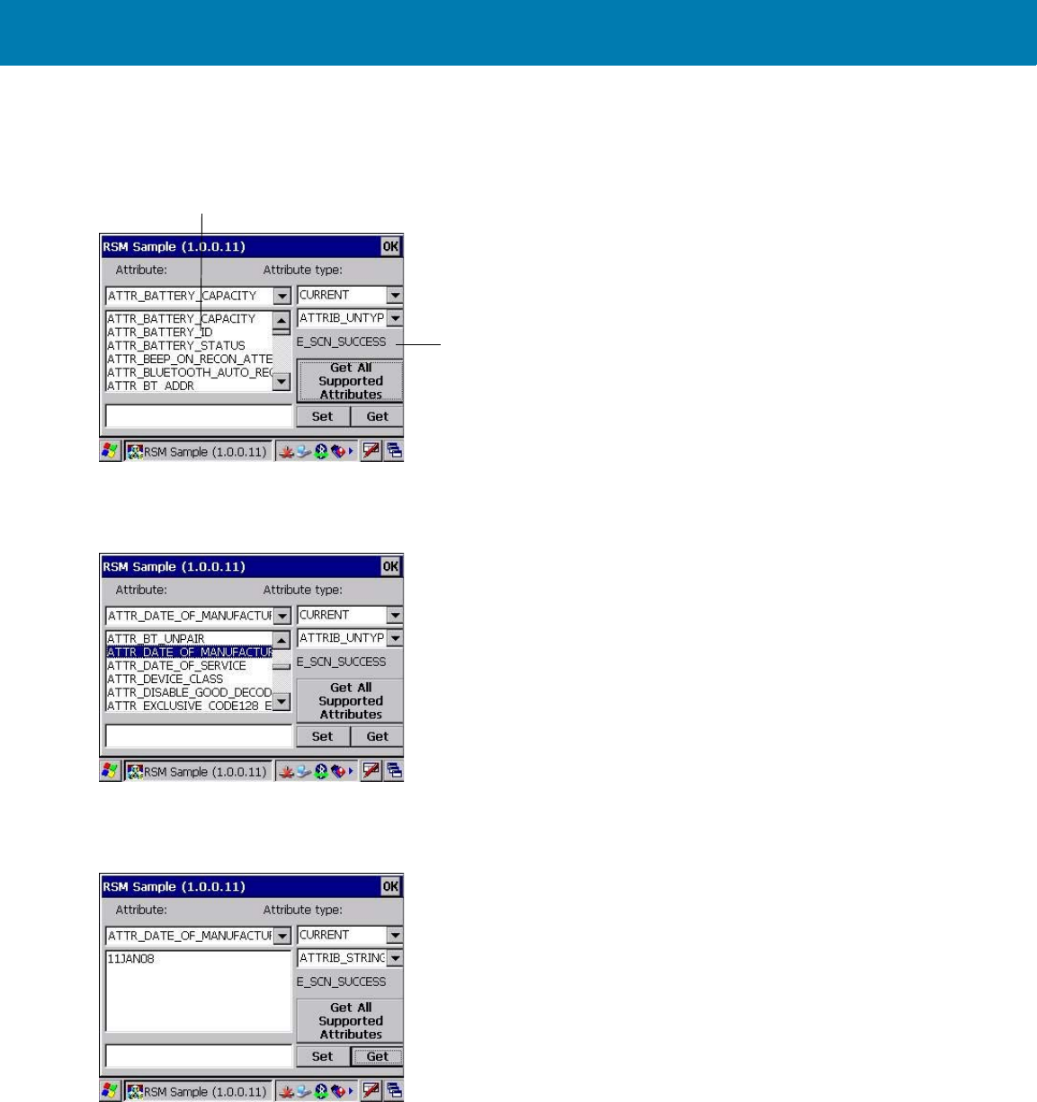
RS507 Update and Configuration
52
4. The Attribute scroll window displays all supported attributes (see Table on page 53) and an operation success
indication.
Figure 40 RSMSample Application - Attribute Scroll Window
fh
5. Select the attribute you wish to change and press the Get button to display the current value of the attribute.
Figure 41 RSMSample Application - Get Button
6. The application returns the current value settings of the attribute.
Figure 42 RSMSample Application - Current Value Settings of Attribute
7. Press again the Get All Supported Attributes button to show all supported attributes (see Figure 43).
8. Select an attribute (see Table ), enter the new value and press the Set button.
Operation Success Indication
Attribute Scroll Window
11 / 16 / 2017 REVIEW ONLY
REVIEW ONLY - REVIEW ONLY - REVIEW ONLY
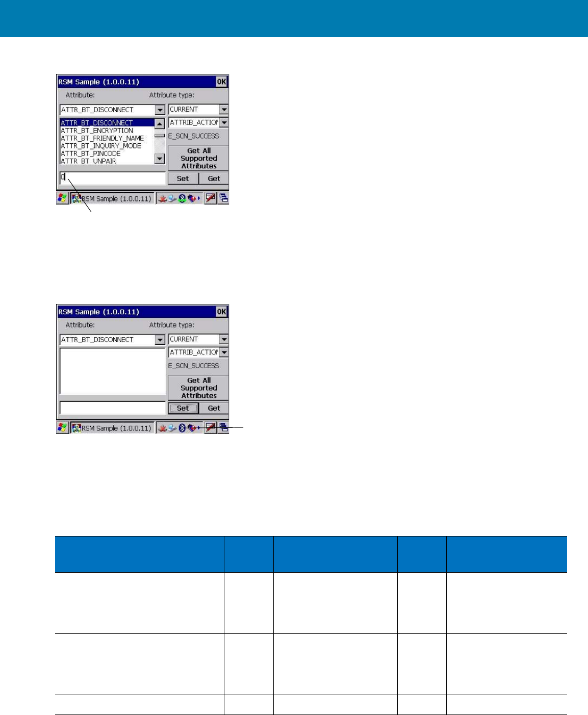
RS507 Update and Configuration
53
Figure 43 RSMSample Application - Setting an Attribute
In the following example, after setting the ATTR_BT_DISCONNECT attribute to 0 (disconnect), the Bluetooth radio
of the Imager is turned off successfully as indicated by the change of the Bluetooth icon from Bluetooth Connection
icon to Bluetooth Disabled icon.
Figure 44 RSMSample Application - Bluetooth Radio Turned Off Successfully Indication
Imager Attributes
Table lists the Imager attributes that can be changed using the RSMSample application.
Value Line
Bluetooth Disabled icon
Table 7 Imager Attributes
Attribute Access Values Factory
Default Description
ATTR_SCANLINE_WIDTH R/W 0 –
(Pick list disabled)
2 – Narrow
(Pick list enabled)
0 Width of laser scan line
or size of Imager's
effective Field of View
(Pick list)
ATTR_DISABLE_GOOD_DECOD
E_LED_BEEP
R/W 0- Enabled automatically
green LED and beep on
good decode.
1- Disabled
Good decode feedback
on Imager
ATTR_MODEL_NUMBER R N/A N/A Model number
11 / 16 / 2017 REVIEW ONLY
REVIEW ONLY - REVIEW ONLY - REVIEW ONLY

RS507 Update and Configuration
54
ATTR_SERIAL_NUMBER R N/A N/A Serial number
ATTR_DATE_OF_MANUFACTUR
E
R N/A N/A Date of manufacture
ATTR_DATE_OF_SERVICE R N/A N/A Last date of repair by
Zebra
ATTR_BT_ADDR R N/A N/A Imager Bluetooth
address
ATTR_BT_AUTHENTICATION R/W 1 - Enabled
0 - Disabled
1 Enable Bluetooth
authentication
(Permanently saved)
ATTR_BT_ENCRYPTION R/W 1 - Enabled
0 - Disabled
1 Enable encryption over
Bluetooth (Permanently
saved)
ATTR_BT_PINCODE R/W Up to six characters “12345” Pin code when
Bluetooth Authentication
is enabled
(Permanently saved)
ATTR_RECONNECT_ATTEMPTS R/W 6 = 30 sec, 7 = 35 sec, 8
= 40 sec, 9 = 45 sec, 10
= 50 sec, 11 = 55 sec, 12
= 60 sec
6 Reconnect attempt
duration when the
Imager is out of range
ATTR_BEEP_ON_RECON_ATTE
MPT
R/W 1 - Enabled
0 - Disabled
0 When enabled, the
Imager emits 5 short
high beeps every 5
seconds while the
reconnection attempt is
in progress
ATTR_HID_AUTO_RECON R/W 0 - Never Reconnect
1 - Reconnect on Data
2 - Reconnect
immediately
0 Auto-reconnect
behavior when
connection is lost.
ATTR_BT_FRIENDLY_NAME R/W Up to 23 characters “RS507” Friendly name displayed
by Bluetooth remote
devices (Permanently
saved).
ATTR_PIN_CODE_TYPE R/W 1 - User prompt
0 - Automatically use
stored PIN code
0 Prompt the user for PIN
code or use PIN code
stored in memory.
Table 7 Imager Attributes
Attribute Access Values Factory
Default Description
11 / 16 / 2017 REVIEW ONLY
REVIEW ONLY - REVIEW ONLY - REVIEW ONLY

RS507 Update and Configuration
55
ATTR_BT_INQUIRY_MODE R/W 1 - Limited
0 - General
0 The used inquiry mode:
Limited: The Imager
finds only an associated
device.
General: The Imager
finds all the visible
devices.
ATTR_EXCLUSIVE_CODE128_E
N
R/W 1 - Enabled
0 - Disabled
0 Ignore Code 128
beginning with 420 and
421
ATTR_MEMS_ENABLE R/W 1 - Enabled
0 - Disabled
Trigger
Model
-0
Triggerl
ess
Model
-1
Motion trigger feature
ATTR_PROXIMITY_ENABLE R/W 1 - Enabled
0 - Disabled
Trigger
Model
-0
Triggerl
ess
Model
-1
Proximity feature
ATTR_PROXIMITY_DISTANCE R/W 0 – Short
1 – Mid
2 – Long
2 Proximity distance
ATTR_PAGING_ENABLE R/W 1 - Enabled
0 - Disabled
0 Paging device enable /
disable
ATTR_PAGING_BEEP_SEQ R/W 0-26 15 Paging beep sequence
Beep pattern values.
ATTR_LOW_BATTERY_IND_EN R/W 1 - Enabled
0 - Disabled
0 Low battery indication.
ATTR_SCAN_TRIG_WAKEUP_EN R/W 1 - Enabled
0 - Disabled
1 Scan trigger serves as
an Imager wake-up
source from low power.
Table 7 Imager Attributes
Attribute Access Values Factory
Default Description
11 / 16 / 2017 REVIEW ONLY
REVIEW ONLY - REVIEW ONLY - REVIEW ONLY

RS507 Update and Configuration
56
ATTR_BLUETOOTH_AUTO_REC
ON
R/W 0 –None
1 - Power on
2 - On when back in
range
3 - On when power is on
and back within range
2 Defines Bluetooth
reconnection scheme
(Permanently saved)
Important: If option 1
(On Power) or 3 (On
when power is on and
back within range) is
set, the pair should be
properly marked and
kept visible on the
Imager and mobile
computer to avoid user
selecting of an unpaired
set.
ATTR_PROXIMITY_CONTINUOU
S_EN
R/W 1 - Enabled
0 - Disabled
0 Proximity continuous
mode (for scanning
packages off conveyer
belt).
ATTR_GOOD_SCANS_DELAY R/W Values 0 -150 (in 100
msec intervals)
0 – No delay
1 – 150 (100 – 15000
msec)
0 Delay between good
scans in proximity
continuous mode
(msec).
ATTR_FORCE_PAIRING_SAVE R/W 0 – Disabled
1 – Enabled
1 Force BD_Address
saving when pairing fails
(Permanently saved).
ATTR_PAGING_ACTIVATE W 0 – Stop
1 – Start
Start / stop Imager
paging
ATTR_BT_DISCONNECT W 0 - Disconnected Bluetooth disconnect
command from terminal
to Imager
ATTR_BT_UNPAIR W 0 - Unpaired Bluetooth un-pair
command from terminal
to Imager.
ATTR_FIRM_VERSION R N/A Imager Firmware
version.
ATTR_DEVICE_CLASS R N/A Imager system class
Table 7 Imager Attributes
Attribute Access Values Factory
Default Description
11 / 16 / 2017 REVIEW ONLY
REVIEW ONLY - REVIEW ONLY - REVIEW ONLY

RS507 Update and Configuration
57
Imager Motion and Proximity Configuration
The Imager proximity and motion feature enables auto-triggering of the Imager upon motion and/or proximity to an
object.
Motion and proximity detection can be enabled or disabled by the mobile computer application such as the Remote
Scanner Management (RSMSample) application of the mobile computer (see “RSMSample Application” on
page 8-50) or by scanning configuration bar codes (see <em_Emphasis>Miscellaneous Imager Options on page
9-70).
Operation Modes
The Imager can be configured to a single or continuous scan operation. In most use cases, a single scan mode is
the preferred operation. However, when scanning packages off a moving conveyer belt, it is sometimes
recommended to use the continuous scan mode (also referred to as 'Proximity Continuous' mode). Continuous
operation automatically results from the combined settings of motion and proximity (enabling or disabling motion
and/or proximity. See Table ). The Imager is provided with motion and proximity enabled by default.
To set new values to the motion and/or proximity attributes, refer to <em_Emphasis>Imager Attributes on page
8-53.
ATTR_BATTERY_STATUS R 0- Unknown
1- Full
2- Medium
3- Empty
4- Charging – full rate
5- Charging – half rate
6- Charging – Trickle
7- Discharging – Battery
Cycle in progress
Battery Status
ATTR_BATTERY_CAPACITY R 0-100 (battery percent)
9999 if error (no battery)
Battery capacity
ATTR_BATTERY_ID R 0 – Simple
1 – Double
2 – Cabled
9999 – Error
Battery ID
Table 7 Imager Attributes
Attribute Access Values Factory
Default Description
NOTE:Once configured, the motion and/or proximity attributes are retained in the Imager memory following
warm or cold boot.
11 / 16 / 2017 REVIEW ONLY
REVIEW ONLY - REVIEW ONLY - REVIEW ONLY

RS507 Update and Configuration
58
Configuring Motion and Proximity by Scanning Bar Codes
To enable or disable motion or proximity, perform cold boot by removing and re-installing the battery (see Remove
the Battery on page 20).
Motion Sensing Control
Disable Motion Trigger
Table 8 Imager Operation Modes
Mode
Number
Parameter States
(Motion / Proximity / Continuous
Scan)
Description
1 Motion: enabled
Proximity: enabled
Continuous scan: disabled
The Imager performs a single scan when moved and
positioned in proximity to an object.
Scanning resumes when the Imager is moved and
re-positioned in proximity to an object.
This mode is a default mode.
2 Motion: disabled
Proximity: enabled
Continuous scan: disabled
The Imager starts to continuously scan when positioned in
proximity to an object. The Imager stops scanning when the
object is out of proximity range.
3 Motion: enabled
Proximity: disabled
Continuous scan: disabled
Upon movement, the Imager performs a single scan and stops.
4 Motion: enabled
Proximity: enabled
Continuous scan: enabled
The Imager performs a continuous scan when moved and
positioned in proximity to an object.
The Imager continues to scan as long as it detects an object
within its range and bar codes are scanned successfully.
The Imager stops scanning if proximity to an object is not
detected, or if the Imager fails to scan three consecutive times.
5 Motion: disabled
Proximity: enabled
Continuous scan: enabled
The description of this operation mode is identical to the
description of mode number 2 in this table.
NOTE:Scanning bar codes for configuring motion and/or proximity is enabled only when the Imager is in
cordless (Bluetooth) configuration.
NOTE:Throughout this section, configuration bar codes shown with asterisks (*) indicate default values.
11 / 16 / 2017 REVIEW ONLY
REVIEW ONLY - REVIEW ONLY - REVIEW ONLY

RS507 Update and Configuration
59
*Enable Motion Trigger
Proximity Sensing Control
Disable Proximity
*Enable Proximity
Proximity Continuous Enable
The Proximity Continuous Enable parameter enables/disables the proximity continuous feature.
*Disable Proximity Continues
Enable Proximity Continues
The Proximity Distance parameter sets the proximity sensitivity range.
Short Range
Mid Range
11 / 16 / 2017 REVIEW ONLY
REVIEW ONLY - REVIEW ONLY - REVIEW ONLY

RS507 Update and Configuration
60
*Long Range
Good Scan indication delay Control
The Good Scan Delay parameter sets a delay between good scans when scanning is in continuous mode.
This delay is effective when:
•Motion detection - Enabled
•Proximity - Enabled
•Proximity continues - Enabled
Or
•Motion detection - Disabled
•Proximity - Enabled
0 msec
200 msec
400 msec
*600 msec
800 msec
1000 msec
11 / 16 / 2017 REVIEW ONLY
REVIEW ONLY - REVIEW ONLY - REVIEW ONLY

RS507 Update and Configuration
61
1200 msec
1400 msec
1600 msec
1800 msec
2000 msec
Real Time Logger
The Imager includes a Real Time Logger application that logs events, errors, exceptions and software diagnostics
of the Imager during its operation. Each log record has a time stamp with a 1ms resolution. The logger time is
synchronized with the host computer’s time. The log is retained only after warm boot. The log memory size is 4 MB
and operates in a cyclic way.
Figure 45 shows the Real Time Logger file content as shown on a host computer screen.
11 / 16 / 2017 REVIEW ONLY
REVIEW ONLY - REVIEW ONLY - REVIEW ONLY
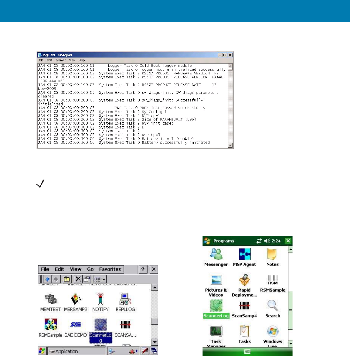
RS507 Update and Configuration
62
Figure 45 Real Time Logger Content Screen
ScannerLog Application
1. Perform a warm boot (see Warm Boot on page 30).
2. Select the Imager ScannerLog application from the Application folder.
Figure 46 ScannerLog Application Icon
3. From the Dialog screen, Select Bluetooth SSI Scanner Driver and press the OK button.
NOTE:When ScannerLog Application is used with a corded connection. Open the ScannerLog application
while the scan application is still running.
ScannerLog Application icon on Windows Mobile screen
ScannerLog Application icon on WT4090 screen
11 / 16 / 2017 REVIEW ONLY
REVIEW ONLY - REVIEW ONLY - REVIEW ONLY
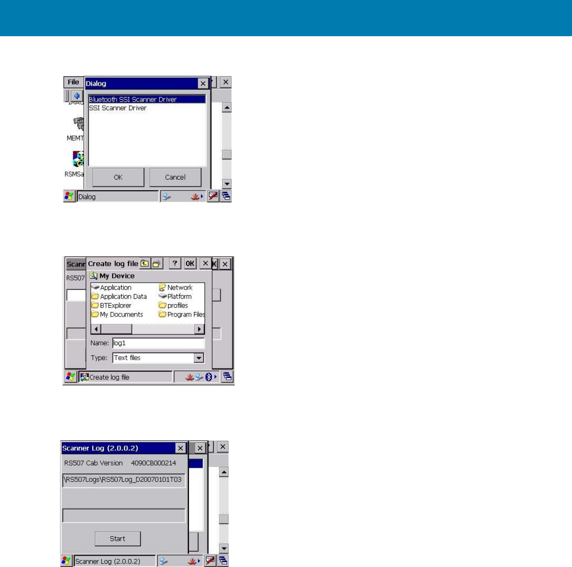
RS507 Update and Configuration
63
Figure 47 Dialog Screen - Bluetooth SSI Scanner Driver
4. Define the name and download location of the log file and press the OK button.
Figure 48 ScannerLog Application - Log File Name and Download Location
5. Press Start to begin downloading.
Figure 49 ScannerLog Application- Starting Download
6. Verify that downloading of the log file starts.
11 / 16 / 2017 REVIEW ONLY
REVIEW ONLY - REVIEW ONLY - REVIEW ONLY
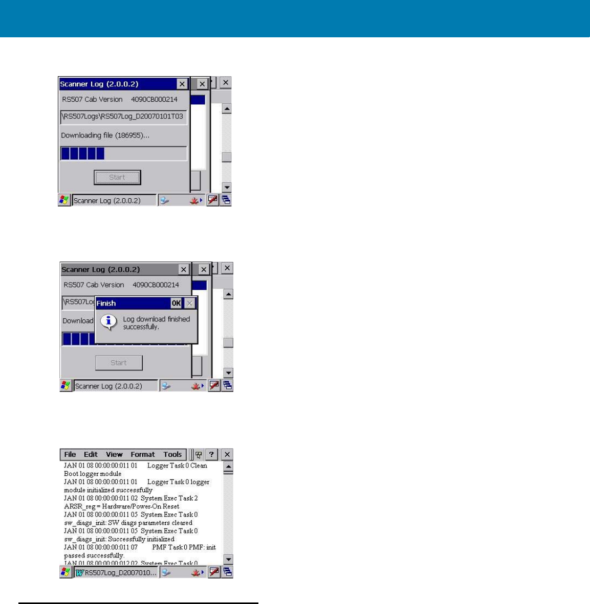
RS507 Update and Configuration
64
Figure 50 ScannerLog Application- Download in Progress
7. Verify that the log file download is completed and press the OK button.
Figure 51 ScannerLog Application- Download Completed
8. On the mobile computer, open the log file to see the content.
Figure 52 ScannerLog Application - Log File Content
Imager Firmware Update
Required Equipment
The following hardware is required for updating the firmware of the Imager:
•Host computer
•Mobile computer
11 / 16 / 2017 REVIEW ONLY
REVIEW ONLY - REVIEW ONLY - REVIEW ONLY
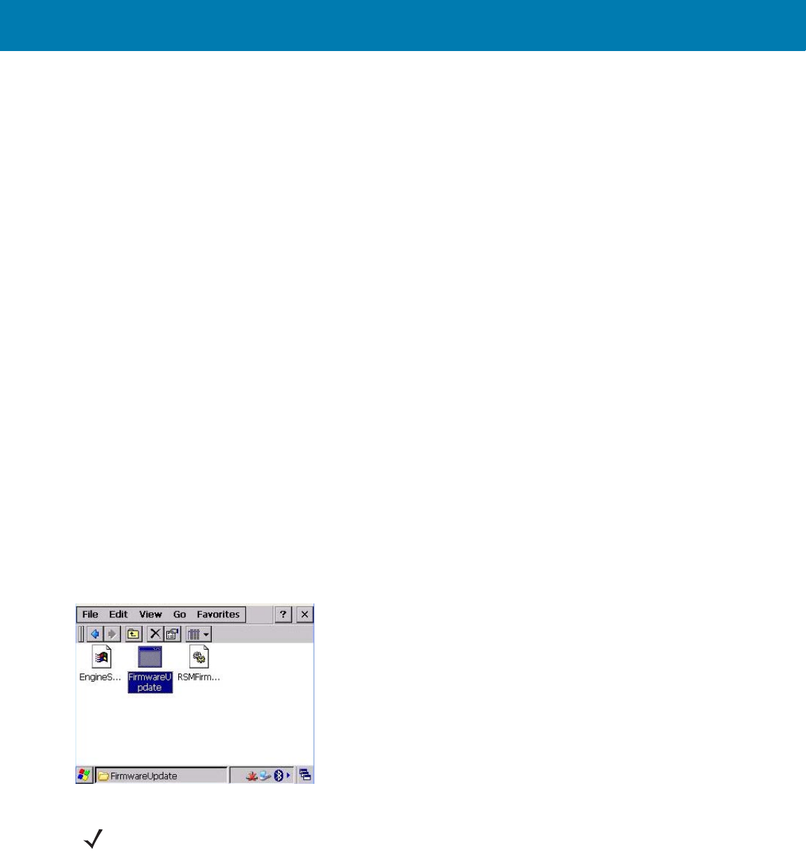
RS507 Update and Configuration
65
•USB / RS232 interface cable or any cradle set-up used for establishing an ActiveSync connection between
the host computer and mobile computer.
The following software is required for updating the firmware of the Imager:
•New Imager firmware file (*.DAT file format)
•CAB file to install in the mobile computer.
•ActiveSync application installed on the host computer and the mobile computer (for copying the new
Imager firmware and RS507 CAB files from the host computer to the mobile computer).
•FirmwareUpdate application installed in the mobile computer (part of the CAB file installation). This
application is used for downloading the firmware file from the mobile computer to the Imager.
Updating the RS507 Firmware
Before using the FirmwareUpdate application:
1. Exit all scanning applications running on the mobile computer.
2. Verify that the mobile computer battery is fully charged or that the mobile computer is connected to an external
power source.
3. When using a corded Imager, verify that the Imager is properly connected to the mobile computer. When using
a cordless Imager verify that the Imager battery is fully charged.
To upgrade the Imager firmware:
1. Connect the Imager to the mobile computer that supports the RS507.
2. Start the FirmwareUpdate application located in the Application folder for WinCE devices or under Start /
Programs for Windows Mobile devices (the FirmwareUpdate application and related documentation can be
downloaded from the Support Central site at: http://www.zebra.com/support.
Figure 53 FirmwareUpdate Application Icon
3. Select the interface method (Bluetooth in the following example).
NOTE:The following screen is displayed only when using the WT4090. In other mobile computers, Bluetooth
mode is selected by default. Press
Yes
(Bluetooth mode) to pair the Imager with the mobile computer (see
Restore Lost Bluetooth Connection on page 26).
11 / 16 / 2017 REVIEW ONLY
REVIEW ONLY - REVIEW ONLY - REVIEW ONLY
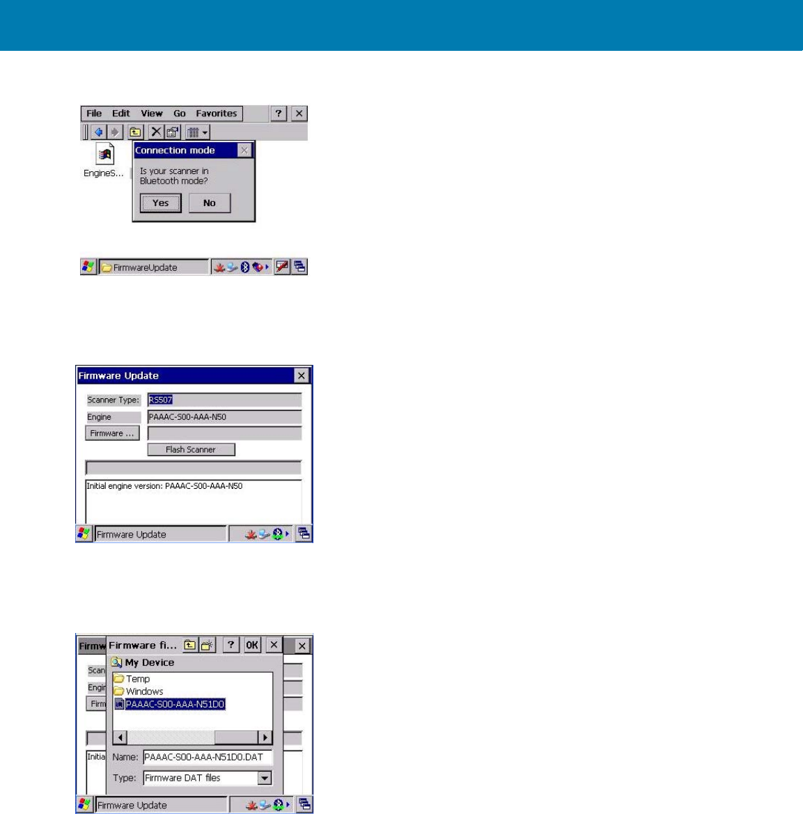
RS507 Update and Configuration
66
Figure 54 Selection of the Bluetooth Interface Mode
4. Press the Firmware button and verify that the application shows the version number of the current firmware of
the Imager.
Figure 55 Firmware Update Screen
5. Copy the *.DAT file to the mobile computer using ActiveSync connection.
6. Press the Firmware… button to select the new firmware *.DAT file and the OK button.
Figure 56 Firmware Update Screen - Selection of *.DAT File
7. Press the Flash Scanner button to start updating the firmware.
11 / 16 / 2017 REVIEW ONLY
REVIEW ONLY - REVIEW ONLY - REVIEW ONLY
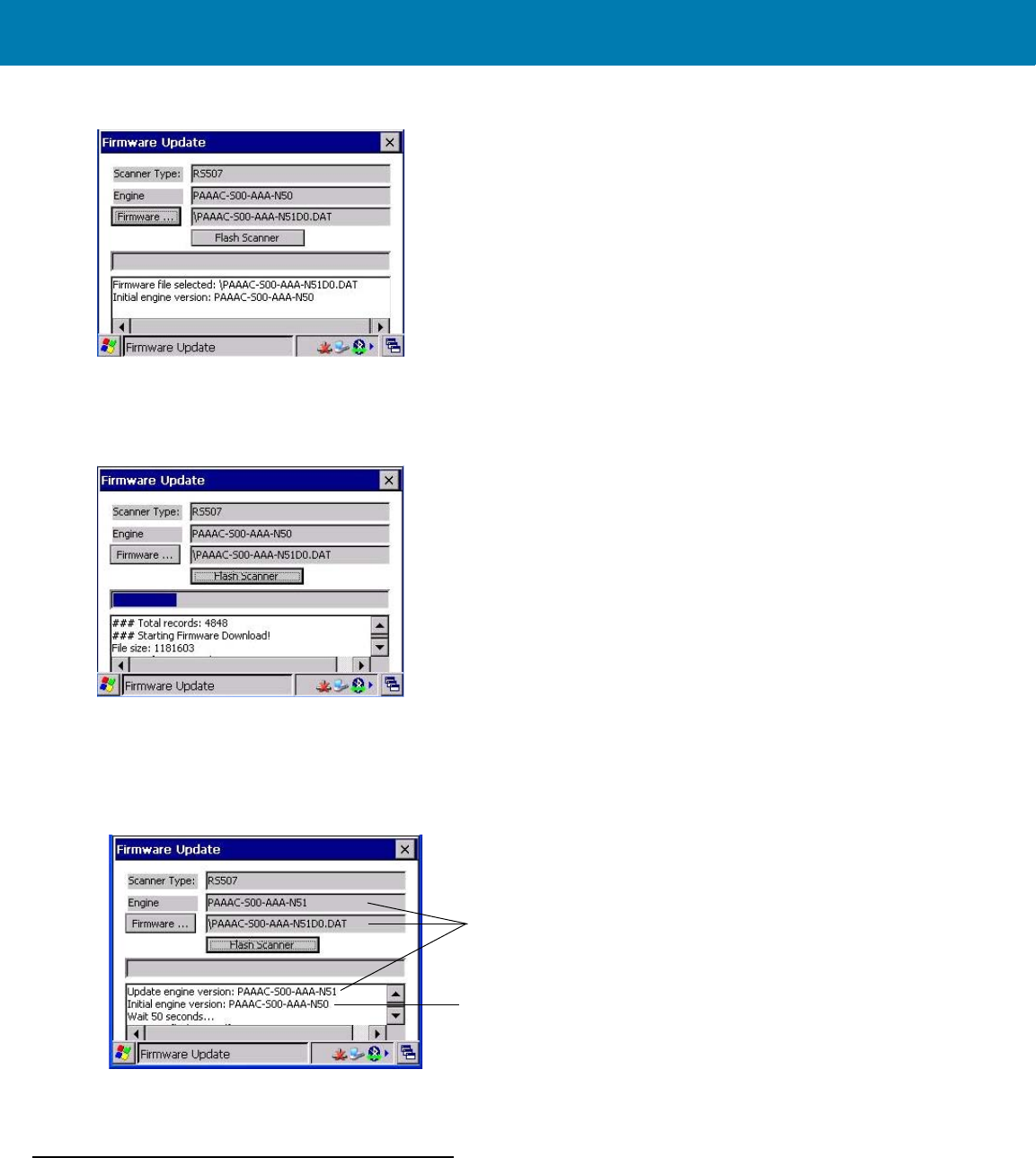
RS507 Update and Configuration
67
Figure 57 Firmware Update Screen - Flash Scanner Button
8. Verify that the firmware download starts. When the download starts, the ### Starting Firmware Download!
message displays. Firmware download is completed when the Update engine version… message is displayed.
Figure 58 Firmware Update Screen - “Starting Firmware Download!” Message
9. Pair the Imager with the mobile computer (see Restore Lost Bluetooth Connection on page 26).
10. Verify that the firmware download is completed by looking at the Initial software version number and the new
software version number.
Figure 59 Firmware Update Screen
11. Press the Esc key on the mobile computer or the X in the top right corner of the application window to exit the
FirmwareUpdate application.
Rapid Deployment Client
The Rapid Deployment (RD) Client application downloads an AirBeam package to a mobile computer connected to
an Imager from a Mobility Services Platform (MSP) Console’s FTP server.
New software version number
Initial software version number
11 / 16 / 2017 REVIEW ONLY
REVIEW ONLY - REVIEW ONLY - REVIEW ONLY
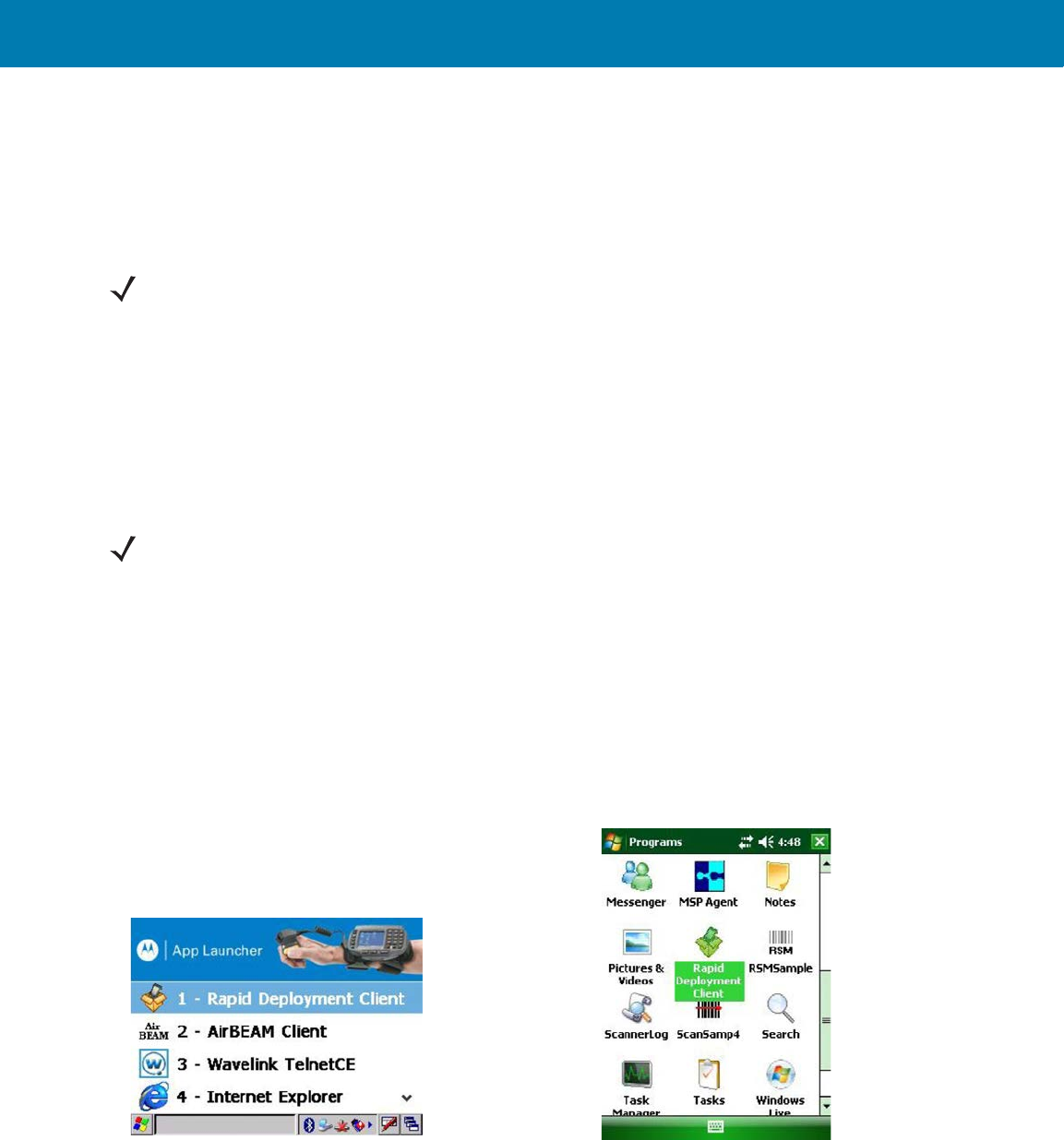
RS507 Update and Configuration
68
The MSP Console is a web-based interface to the wireless infrastructure monitoring and management tools
provided by the MSP Lite or MSP Enterprise server.
AirBeam packages transferred to the FTP server, are downloaded to mobile computers connected to the wireless
network. The location of AirBeam packages are encoded in deployment bar codes. When an Imager captures a
deployment bar code, the AirBeam package(s) is downloaded from the FTP server to the Imager via the mobile
computer. A single deployment bar code can be captured by many Imagers.
The AirBeam package can be downloaded from the Support Central web site (Service Information on page 14).
The package includes:
•Mobile computer's RS507 enhancement .APF file
•Compatible RS507 Firmware .APF file.
The .APF file is used for management and distribution of the AirBeam package when the file is transferred from the
MSP to the Imager connected to the mobile computer over the Bluetooth.
To download the AirBeam package from the remote MSP server:
1. Install the RS507_xxx.APF file on the MSP server (refer to MSP server documentation).
2. Connect the mobile computer to the network via WLAN, or other cradle or cable connection (refer to you
mobile computer user guide).
3. From the App Launcher (or Windows Mobile Programs) screen of your mobile computer, start the Rapid
Deployment Client application.
Figure 60 Rapid Deployment Client Application Icon
4. The Rapid Deployment Client Application searches for Imagers. Press the Pair button displayed on the screen.
NOTE:For detailed information about the MSP Console, MSP Lite/MSP Enterprise servers and creating
deployment bar codes, refer to the MSP User Guide.
NOTE:Make sure that the enhancement APF file is deployed on the mobile computer before you start the
deployment.
Rapid Deployment Client Application Icon
on Windows Mobile Screen
Rapid Deployment Client Application Icon
on WT4090 Screen
11 / 16 / 2017 REVIEW ONLY
REVIEW ONLY - REVIEW ONLY - REVIEW ONLY
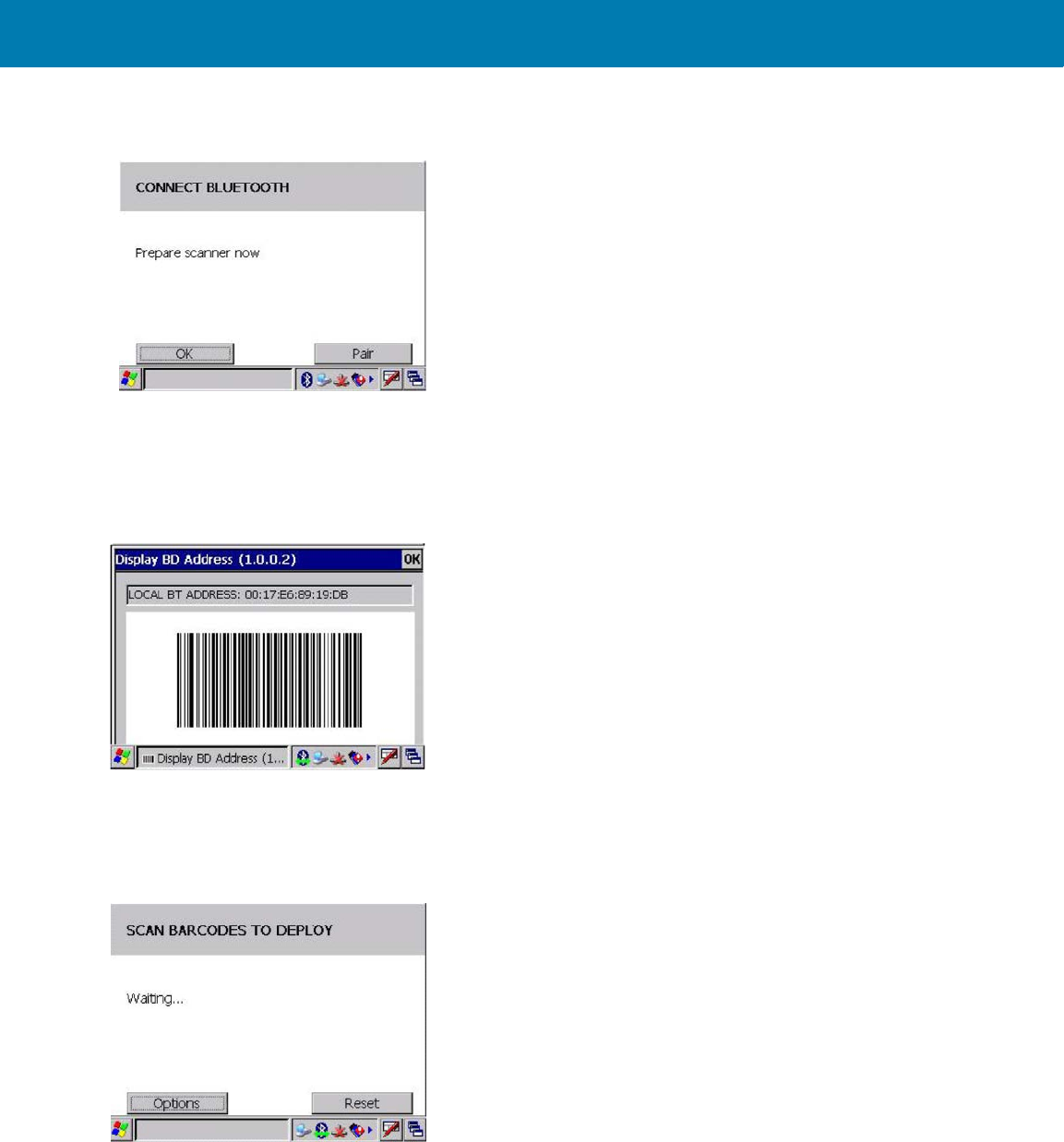
RS507 Update and Configuration
69
Figure 61 Rapid Deployment Client Application - Bluetooth Connection Screen
5. The Display BD Address utility is displayed. Use the Imager to scan the pairing bar code from the mobile
computer screen and press the ESC button on the mobile computer.
Figure 62 Display BD Address Utility - Pairing Bar Code
6. The Scan bar code to deploy screen is displayed. Scan the deployment bar code provided by your system
administration to start the update process.
Figure 63 Scan Bar Code to Deploy Screen
During the update, process reports are display on the screen and the Imager LEDs show the following
indications:
•Flashing red - firmware file is downloading
•Steady red - firmware file is extracted inside the Imager
•Steady Green and a single beep - firmware update is completed
11 / 16 / 2017 REVIEW ONLY
REVIEW ONLY - REVIEW ONLY - REVIEW ONLY

70
Miscellaneous Imager
Options
Introduction
The Imager is intended to operate hand in hand with the mobile computer to which it is connected.
The mobile computer automatically loads configuration data whenever connected to an Imager (corded or
cordless). This operation does not require scanning configuration bar codes. Using configuration bar codes is only
available for a cordless Imager when decontrolled from the mobile computer.
It is recommended to use configuration bar codes only for setting parameters that cannot be configured by the
other mobile computer application.
The Imager ships with the settings shown in Table 9 on page 71 (also see <em_Emphasis>Appendix , Standard
Default Parameters for host device and miscellaneous defaults). If the default values suit the requirements,
programming is not necessary.
To return all features to default values, scan the Set Default Parameter on page 72. Throughout the programming
bar code menus, asterisks indicate (*) default values.
Scanning Sequence Examples
In most cases, scanning one bar code sets the parameter value. For example, to set the beeper tone to high, scan
the High Frequency (beeper tone) bar code listed under Beeper Tone on page 75. The Imager issues a fast
warble beep and the LED turns green, signifying a successful parameter entry.
NOTE:Imager parameters set by scanning configuration bar codes, persist in the Imagers memory.
NOTE:Most computer monitors allow scanning the bar codes directly on the screen (when using the imaging
engine). When scanning from the screen, be sure to set the document magnification to a level where you can see
the bar code clearly, and bars and/or spaces are not merging.
*High Volume
(00h) Feature/Option
* Indicates Default
Option Hex Value for
programming via SSI
command
11 / 16 / 2017 REVIEW ONLY
REVIEW ONLY - REVIEW ONLY - REVIEW ONLY