Zebra Technologies TFF-1011L WhereCall III & WhereCall III PLC User Manual WhereNet ation
Zebra Technologies Corporation WhereCall III & WhereCall III PLC WhereNet ation
UserManual.wiki
>
Zebra Technologies
>
TFF-1011L User Manual
>
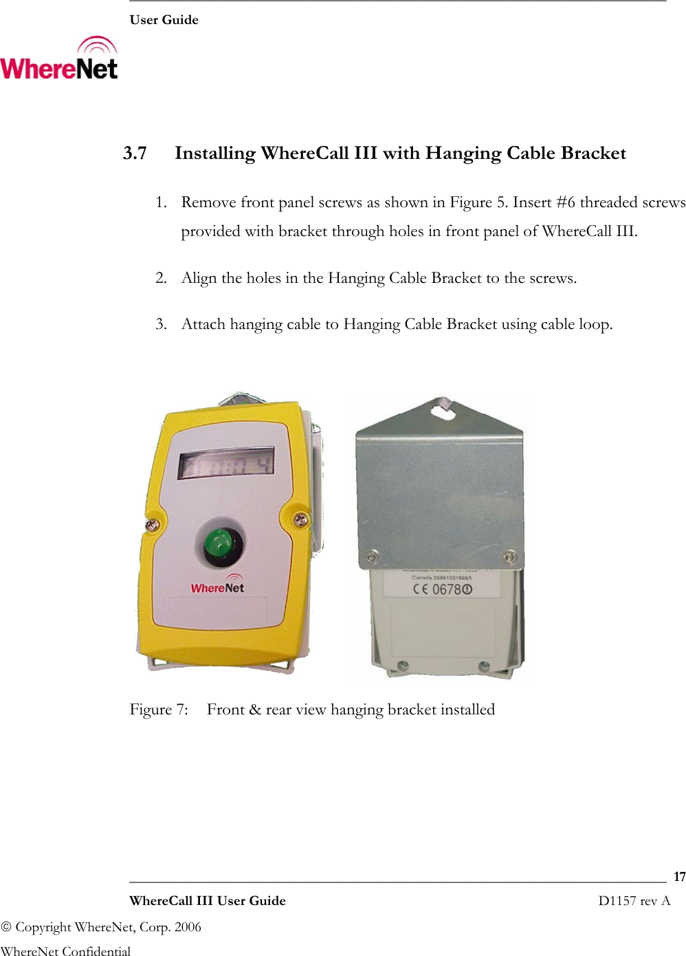
User Manual
Contents
1.
Users Manual
2.
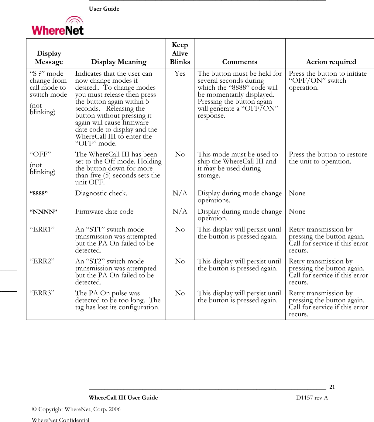
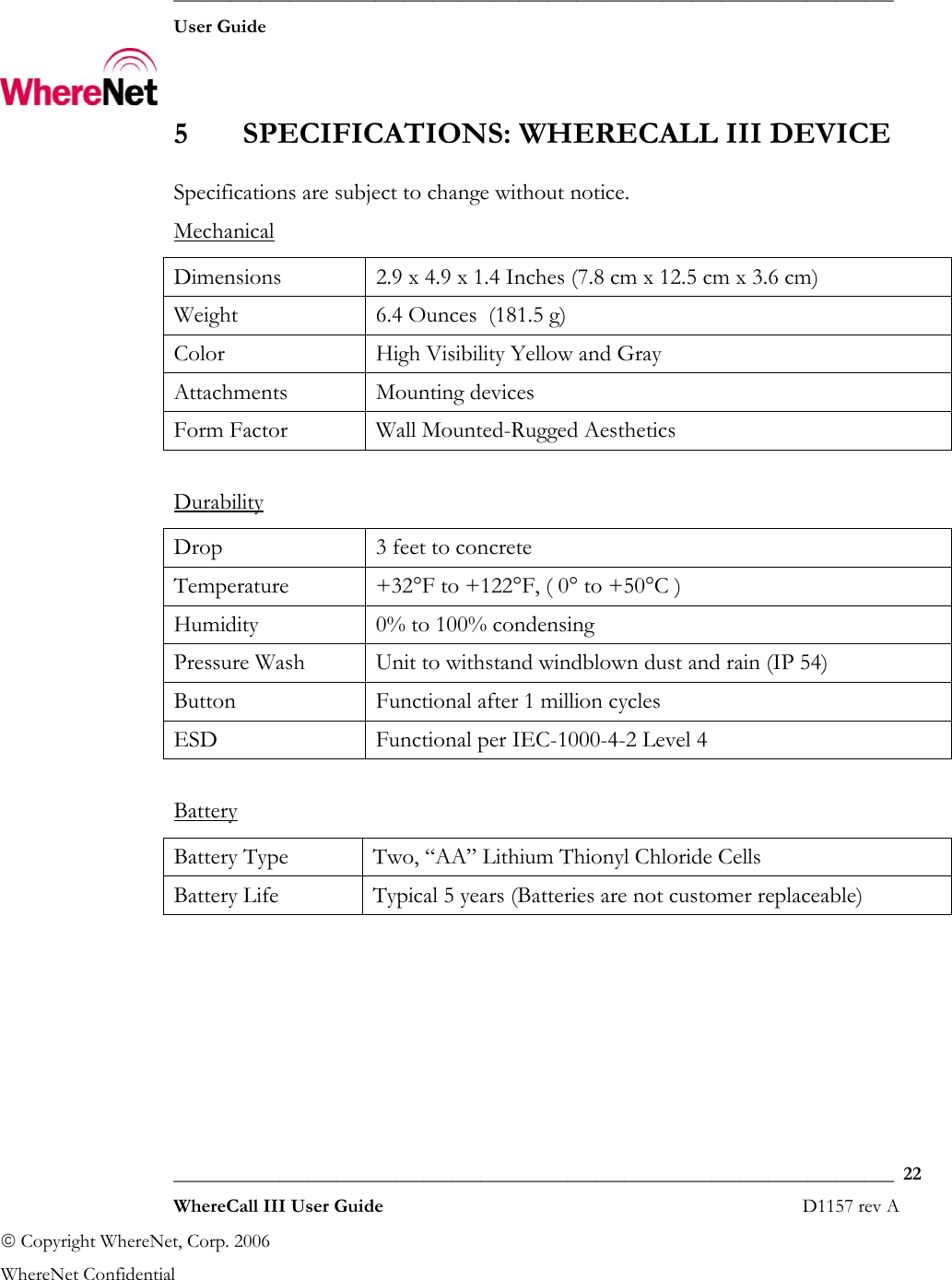
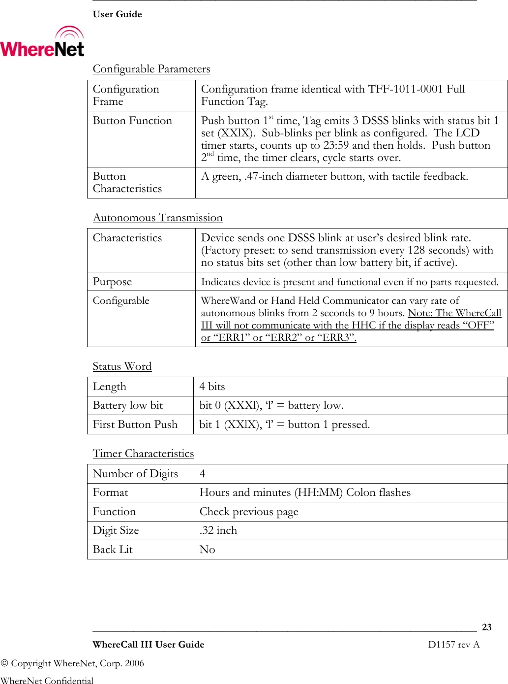
User Manual
User Manual
Navigation menu
Upload a User Manual
Namespaces
Wiki Guide
HTML
PDF
Info
Views
User Manual
Discussion / Help
Navigation