Zebra Technologies TFF-1011L WhereCall III & WhereCall III PLC User Manual WhereNet ation
Zebra Technologies Corporation WhereCall III & WhereCall III PLC WhereNet ation
Contents
- 1. Users Manual
- 2. User Manual
User Manual
___________________________________________________________________________
User Guide
___________________________________________________________________________ 1
WhereCall III User Guide D1157 rev A
© Copyright WhereNet, Corp. 2006
WhereNet Confidential
WhereCall III User Guide

___________________________________________________________________________
User Guide
___________________________________________________________________________ 2
WhereCall III User Guide D1157 rev A
© Copyright WhereNet, Corp. 2006
WhereNet Confidential
User Guide Special Notices
____________ Warnings call attention to a procedure or practice that could result in personal
injury if not correctly performed. Do not proceed until you fully understand and
meet the required conditions.
____________
____________ Cautions call attention to an operation procedure or practice that could damage
the product if not correctly performed. Do not proceed until understanding and
meeting these required conditions.
CAUTION
____________
____________ Notes provide information that can be helpful in understanding the operation of
the product.
NOTE
____________

___________________________________________________________________________
User Guide
___________________________________________________________________________ 3
WhereCall III User Guide D1157 rev A
© Copyright WhereNet, Corp. 2006
WhereNet Confidential
FCC Requirements
FCC Compliance Statement
This device complies with Part 15 rules. Operation is subject to the following two
conditions:
1. This device may not cause harmful interference, and
2. This device must accept any interference received, including interference that may
cause undesired operation. The user is cautioned that any changes or modifications not
expressly approved by WhereNet Corp. could void the user’s authority to operate the
equipment.
Canadian DOC Compliance Statement
This Class B digital apparatus complies with Canadian ICES-003.
Cet appareil numérique de la classe B est conforme à la norme NMB-003 du Canada.
____________
There are no user serviceable parts inside. Do not attempt to open case or change
batteries. Only WhereNet personnel may change batteries.
CAUTION
____________

___________________________________________________________________________
User Guide
___________________________________________________________________________ 4
WhereCall III User Guide D1157 rev A
© Copyright WhereNet, Corp. 2006
WhereNet Confidential
Document Revision History
Revision Change Change Description Date
A C01157 Initial Release 08/02/06

___________________________________________________________________________
User Guide
___________________________________________________________________________ 5
WhereCall III User Guide D1157 rev A
© Copyright WhereNet, Corp. 2006
WhereNet Confidential
Table of Contents Page
1 OVERVIEW 7
2 COMPONENTS 8
3 INSTALLATION & MOUNTING 9
3.1 POLY-LOCK 9
3.2 MOUNTING WHERECALL III WITH POLY-LOCK 11
3.3 WHERETAG FOAM TAPE SQUARES 12
3.4 MOUNTING WHERECALL III WITH FOAM TAPE SQUARES 12
3.5 MOUNTING WHERECALL III WITH SCREWS 15
3.6 HANGING CABLE BRACKET 16
3.7 INSTALLING WHERECALL III WITH HANGING CABLE BRACKET17
4 OPERATION OF THE WHERECALL III 18
5 SPECIFICATIONS: WHERECALL III DEVICE 22
Table of Figures Page
FIGURE 1: POLY-LOCK FASTENER WITH ADHESIVE BACKING 10
FIGURE 2: POLY-LOCK & FOAM TAPE POSITIONS 10
FIGURE 3: FOAM TAPE SQUARES 12
FIGURE 4: SCREW MOUNTING TEMPLATE 14
FIGURE 5: COVER SCREWS 15
FIGURE 6: HANGING CABLE BRACKET 16
FIGURE 7: FRONT & REAR VIEW HANGING BRACKET INSTALLED 17

___________________________________________________________________________
User Guide
___________________________________________________________________________ 6
WhereCall III User Guide D1157 rev A
© Copyright WhereNet, Corp. 2006
WhereNet Confidential

___________________________________________________________________________
User Guide
___________________________________________________________________________ 7
WhereCall III User Guide D1157 rev A
© Copyright WhereNet, Corp. 2006
WhereNet Confidential
1 OVERVIEW
The WhereNet WhereCall System allows users in manufacturing and assembly
operations to request service or specific parts without leaving their workstations.
Specific parts or service requests may be assigned to individual WhereCall IIII devices
so that users may indicate which item is needed. For example, an assembly worker
using several parts: Each part is associated with a separate WhereCall III device
located in the workstation. By pressing the green button on the WhereCall III device,
a radio signal is sent by the WhereCall System to the computer system in the supply
area, indicating which workstation requires the specified part or service.
There WhereCall III also operates in an optional “switch mode”. This mode can be
used to indicate a status; the display will blink either “-ON” or “–OFF” and will
toggle each time the button is pressed.
To insure that the WhereCall system is in constant operation, real-time monitoring
using an “I’m Still Alive” blinking transmission advises the system supervisor of the
status of each WhereCall III device.
WhereCall III devices may be individually labeled for identification by applying a
user-supplied label to the recessed area on the front panel below the green button.
The WhereCall III may be mounted in a work area with removable fasteners, double-
sided foam tape or with mounting brackets and screws. Overhead installation is also
possible by using cable mounting (Refer to Section 3, Installation and Mounting).

___________________________________________________________________________
User Guide
___________________________________________________________________________ 8
WhereCall III User Guide D1157 rev A
© Copyright WhereNet, Corp. 2006
WhereNet Confidential
2 COMPONENTS
The WhereCall System consists of four major components: the WhereCall III
device; a location antenna; a location processor and a WhereNet computer server.
This document details only the WhereCall III device.
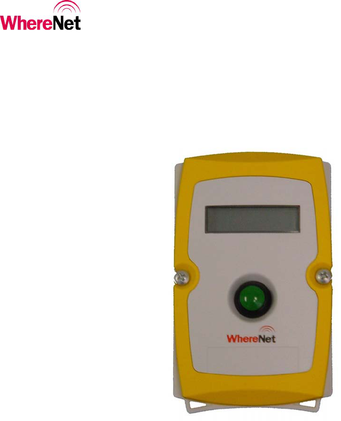
The WhereCall III is a palm-sized device approximately 3 inches by 5 inches, 1 inch
thick, in a yellow and gray colored case. A green colored actuator button is in the
center of the device. A liquid crystal display (LCD) screen is located above the
button.
The WhereNet Location Antenna receives radio signals from the WhereCall III
device when the work station user sends a call requesting parts by pressing the green
button on the WhereCall III. These signals are transferred by cable to the WhereNet
Location Processor.
The WhereNet Location Processor converts signals from the antenna(s) and sends
them to the WhereNet computer server. A message is generated by the server and
sent to the user’s computer system indicating that a part is needed at the location of
the WhereCall III device.
If necessary, the WhereWand hand-held communicator allows the WhereNet
technician to configure the WhereCall III device.

___________________________________________________________________________
User Guide
___________________________________________________________________________ 9
WhereCall III User Guide D1157 rev A
© Copyright WhereNet, Corp. 2006
WhereNet Confidential
3 INSTALLATION & MOUNTING
The WhereCall III may be mounted in a work area with removable fasteners, double-
coated foam tape, hanging brackets, or with mounting screws. Overhead installation
is also possible using cable mounting.
Each WhereCall III must be mounted in a location to provide an unobstructed view
in at least one direction. To maintain communication with the Location Antennas,
do not install the WhereCall III inside a metal enclosure such as a metal cabinet.
3.1 Poly-Lock
A plastic, adhesive-backed fastener, Poly-Lock uses mushroom-shaped contact points
that overlap and snap together, forming a strong attachment that can be separated by
a forceful pull. Poly-Lock is not included with the WhereCall III, but is available
from WhereNet in precut squares. Contact your WhereNet account manager for parts
information.
___________________________________________________________________________
User Guide
___________________________________________________________________________ 10
WhereCall III User Guide D1157 rev A
© Copyright WhereNet, Corp. 2006
WhereNet Confidential
Figure 1: Poly-Lock fastener with adhesive backing
Figure 2: Poly-Lock & foam tape positions
A
pply Tape
A
pply Tape

___________________________________________________________________________
User Guide
___________________________________________________________________________ 11
WhereCall III User Guide D1157 rev A
© Copyright WhereNet, Corp. 2006
WhereNet Confidential
3.2 Mounting WhereCall III with Poly-Lock
Do not apply the poly-lock when the temperature is below 60°F (15°C) or
above 90°F (32°C).
____________
CAUTION
1. Select the desired location in the workstation to mount the WhereCall III.
____________
2. Clean the mounting surface and the back plate of the WhereCall III with
isopropyl alcohol.
3. Select a pair (they are shipped in attached pairs)of Poly-Lock squares, remove
the adhesive backing and press them to the mounting surface, sticky side
down (see Figure 2).
4. Remove the adhesive backing from three additional pairs of Poly-Lock
squares and affix them to the back plate of the WhereCall III to match the
fastener locations on the mounting surface.
5. You should now have four pairs of Poly-Lock attached to the back of the
WhereCall III. Remove the adhesive backing from all four squares.
6. While holding the WhereCall III, aligned with the fasteners on the mounting
surface. Gently press the unit against the mounting surface to assure that the
adhesive on the squares is bonded to the both surfaces.

___________________________________________________________________________
User Guide
___________________________________________________________________________ 12
WhereCall III User Guide D1157 rev A
© Copyright WhereNet, Corp. 2006
WhereNet Confidential
3.3 WhereTag Foam Tape Squares
WhereTag foam tape, both sides adhesive, provides a secure, semi-permanent
mounting method for the WhereCall III device. Foam tape is not included with the
WhereCall III. Contact your WhereNet Account Manager for parts information.
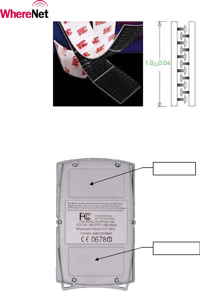
Figure 3: Foam tape squares
____________
“Double sticky” tape applies a layer of permanent adhesive film to both surfaces.
Care should be taken in the application of foam tape; once applied it is difficult to
remove.
NOTE
____________
3.4 Mounting WhereCall III with Foam Tape Squares
____________
Do not apply the foam tape when the temperature is below 60°F (15°C) or
above 90°F (32°C).
CAUTION
____________ 1. Select the desired location to mount the WhereCall III.

___________________________________________________________________________
User Guide
___________________________________________________________________________ 13
WhereCall III User Guide D1157 rev A
© Copyright WhereNet, Corp. 2006
WhereNet Confidential
2. Clean the mounting surface and the back plate of the WhereCall III with
isopropyl alcohol.
3. Select two foam tape squares, remove the adhesive backing from one side
only and apply them to the back plate of the WhereCall III as shown in
Figure 2.
4. Remove the adhesive backing from the exposed surface of the tape squares.
5. While holding the WhereCall III, aligned to the desired position. Gently press
the unit onto the mounting surface.
___________________________________________________________________________
User Guide
___________________________________________________________________________ 14
WhereCall III User Guide D1157 rev A
© Copyright WhereNet, Corp. 2006
WhereNet Confidential
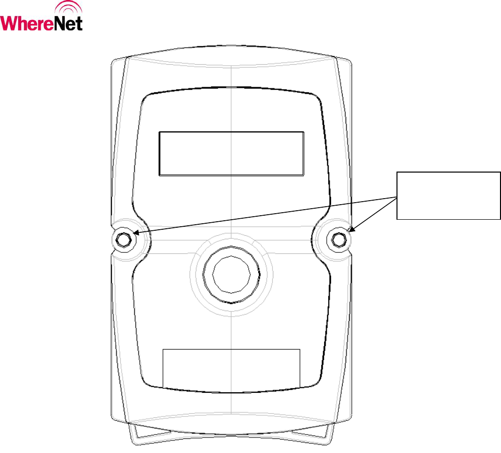
Remove cover
screws; Insert #6
screws here
Dimension from
center to center of
screws = 2.696”
Housing depth at
screw = 1.10”
Figure 4: Screw mounting template (drawing is actual size).
___________________________________________________________________________
User Guide
___________________________________________________________________________ 15
WhereCall III User Guide D1157 rev A
© Copyright WhereNet, Corp. 2006
WhereNet Confidential
3.5 Mounting WhereCall III with screws
The WhereCall III may be directly mounted to a surface such as a wall, post, or desk.
For correct screw placement, use the Screw Mounting Template provided in this
User’s Guide (see Figure 4).
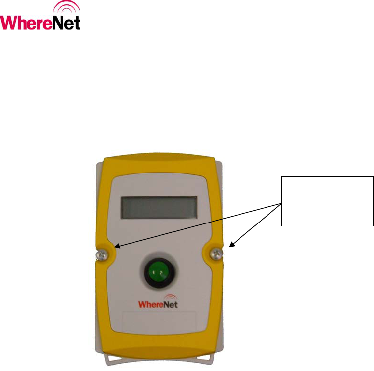
Remove cover
screws, replace
with #6 screws
Figure 5: Cover screws
1. Select the desired location to mount the WhereCall III.
2. Position the mounting template on the mounting surface.
3. Place a pencil, pen or metal scribe on the ‘Insert screw here’ points as shown
in Fig. 4, puncture the template and mark the mounting surface.
___________________________________________________________________________
User Guide
___________________________________________________________________________ 16
WhereCall III User Guide D1157 rev A
© Copyright WhereNet, Corp. 2006
WhereNet Confidential
4. Drill screw pilot holes as needed into the mounting surface.
5. Remove front cover screws as shown in Figure 5.
6. Inserts #6 screws through holes in the front panel of the WhereCall III and
gently tighten to a snug fit (12 to 15 in-oz). Do not distort case by over-
tightening.
____________
Do not over-tighten screws. Damage to the WhereCall III might result if screws
are over-tightened.
CAUTION
____________
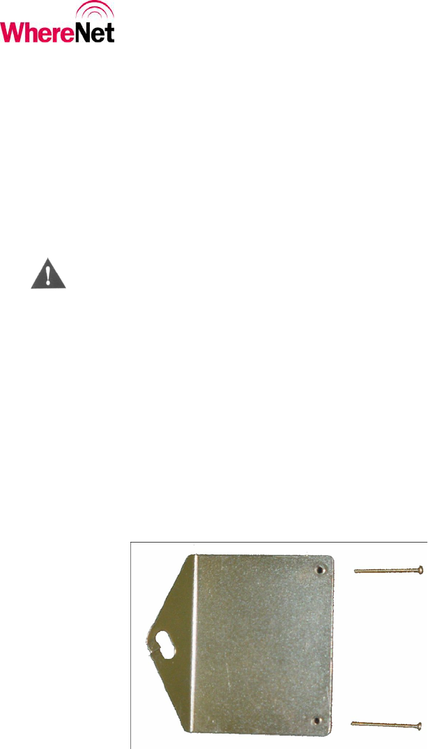
3.6 Hanging Cable Bracket
The WhereCall III may be installed from an overhead cable for ease of use in a
workstation where mounting on flat surfaces is unsafe or inconvenient. Hanging cable
brackets are not included with the WhereCall III but are available from WhereNet.
Contact your WhereNet Account Manager for parts information.
Figure 6: Hanging cable bracket
___________________________________________________________________________
User Guide
___________________________________________________________________________ 17
WhereCall III User Guide D1157 rev A
© Copyright WhereNet, Corp. 2006
WhereNet Confidential
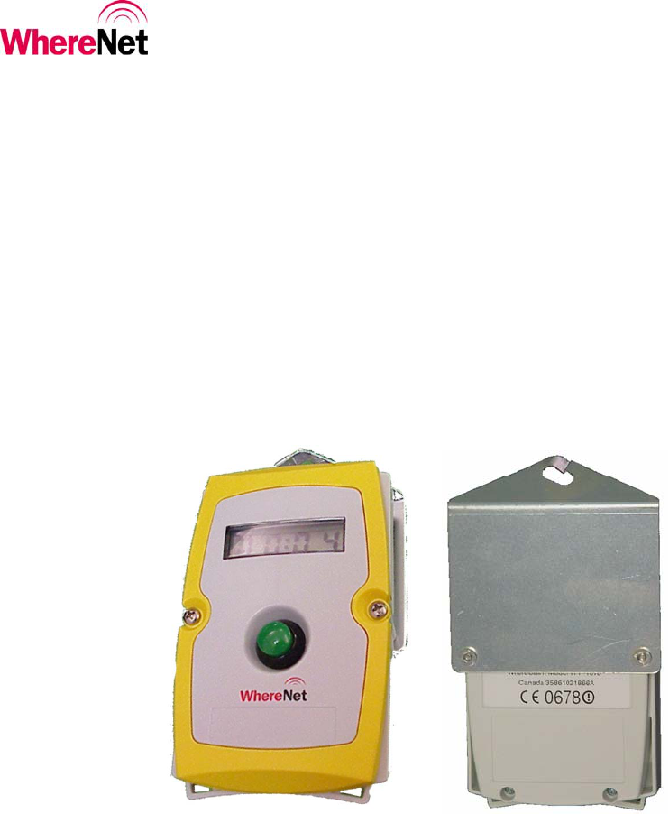
3.7 Installing WhereCall III with Hanging Cable Bracket
1. Remove front panel screws as shown in Figure 5. Insert #6 threaded screws
provided with bracket through holes in front panel of WhereCall III.
2. Align the holes in the Hanging Cable Bracket to the screws.
3. Attach hanging cable to Hanging Cable Bracket using cable loop.
Figure 7: Front & rear view hanging bracket installed

___________________________________________________________________________
User Guide
___________________________________________________________________________ 18
WhereCall III User Guide D1157 rev A
© Copyright WhereNet, Corp. 2006
WhereNet Confidential
4 OPERATION OF THE WHERECALL III
The WhereCall III is a wireless messaging device that is capable of transmitting
simple messages to the WhereNet Infrastructure. These messages can range from
a call for parts for line side material replenishment to a request for supervisor
assistance. There are three modes of operation, Button or Call, Switch, and OFF.
The WhereCall III is shipped in the “OFF” mode.
In button or Call mode the WhereCall III can be used for parts call and other
operations that do not require an indication as to whether the request was
completed. In this mode, the operator presses the button to send the request
message. The display on the WhereCall III will flash the word “CALL” for one
minute and then start to count up in minutes since the call was made. This lets the
operator easily verify how long it has been since they made their request. In the
button mode the WhereCall III will transmit “switch ID 0”.
To turn the WhereCall III on when it is “OFF” (the display will show non
blinking OFF). Press the button once and the tag will resume operation in either
the Call mode or the Switch mode depending on the mode it was in when the off
mode was selected.
In switch mode, the display toggles between “-ON” and “-OFF”. The normal
starting state is “-OFF”. If the operator presses the button, then the WhereCall
will send a message signaling the change in state and the display will change to “-
ON” and transmit “Switch ID 1”. The next button press will cause a new message
to be sent signaling the change of state and the display will change back to
“-OFF” and transmit “Switch ID 0”. In the switch mode the WhereCall III will
send multiple transmissions; at 0, 1, 5, 10, 15, 30, 90, 150 minute intervals and
then every hour after that.
To change modes between Call mode and Switch mode or visa versa; press and hold
the button until the display indicates either “b ?” or “S ?”. (Do not release the
button while the display shows “8888” rather continue to keep the button depressed.)
When either of these is displayed immediately release the button then press and
release it again within five seconds; this will change the operational mode.

___________________________________________________________________________
User Guide
___________________________________________________________________________ 19
WhereCall III User Guide D1157 rev A
© Copyright WhereNet, Corp. 2006
WhereNet Confidential
To turn the tag to the OFF mode from either Call mode or Switch mode. Press and
hold the button until the display shows 8888. Then release the button the display will
indicate a four digit number for a few seconds and then show OFF. The WhereCall
III is now OFF and all transmissions are disabled.
These messages are displayed on the WhereCall III’s LCD display. The display
has large characters so that it can be read from distances up to 10 feet away. The
sturdy push-button is recessed to prevent accidental presses.
A variant of WhereCall III, the WhereCall III PLC, provides for automated call
requests by replacing the call button with a sealed connector that can be
interfaced to intelligent shop floor equipment.
The WhereCall III provides long battery life, typically in excess of 5 years.
Additionally, the batteries are replaceable providing a long product life.

___________________________________________________________________________
User Guide
___________________________________________________________________________ 20
WhereCall III User Guide D1157 rev A
© Copyright WhereNet, Corp. 2006
WhereNet Confidential
Display
Message Display Meaning
Keep
Alive
Blinks Comments Action required
“CALL”
(blinking)
Button blinks are being
transmitted. Yes This mode will continue for
60 seconds following a
button press.
None
“HH:MM”
Colon
flashing
Indicates the elapsed time
from the last button press. Yes The time advances until it
reaches 23:59 then holds
until the button is pressed.
None
“CALL”
displayed for
more than
60 seconds.
If the button is pressed while
the display indicates CALL,
the display will reset for
another 60 seconds.
Yes The WhereCall will send a
“Button Blink” for each
button press.
None
“-OFF”
switch mode
(blinking)
Switch mode where the tag
will transmit Switch ID 0. Yes From Call mode, the button
must be held for several
seconds after the “8888”
code is displayed and until
the code “S?” is shown.
None
“-ON”
switch mode
(blinking)
Switch mode where the tag
will transmit Switch ID 1. Yes Once in switch mode, each
button press will toggle
from “-OFF” to “-ON” and
vice versa.
None
“b ?” mode
change from
switch mode
back to call
mode
(not
blinking)
Indicates that the user can
now change modes if
desired.. To change modes
you must release then press
the button again within 5
seconds. Releasing the
button without pressing it
again will cause firmware
date code to display and the
WhereCall III to enter the
“OFF” mode.
Yes The button must be held for
several seconds during
which the “8888” code will
be momentarily displayed.
Pressing the button again
will generate a “CALL”
response.
Press the button to initiate
“CALL” operation.

___________________________________________________________________________
User Guide
___________________________________________________________________________ 21
WhereCall III User Guide D1157 rev A
© Copyright WhereNet, Corp. 2006
WhereNet Confidential
Display
Message Display Meaning
Keep
Alive
Blinks Comments Action required
“S ?” mode
change from
call mode to
switch mode
Indicates that the user can
now change modes if
desired.. To change modes
you must release then press
the button again within 5
seconds. Releasing the
button without pressing it
again will cause firmware
date code to display and the
WhereCall III to enter the
“OFF” mode.
Yes The button must be held for
several seconds during
which the “8888” code will
be momentarily displayed.
Pressing the button again
will generate a “OFF/ON”
response.
Press the button to initiate
“OFF/ON” switch
operation.
(not
blinking)
“OFF” The WhereCall III has been
set to the Off mode. Holding
the button down for more
than five (5) seconds sets the
unit OFF.
No This mode must be used to
ship the WhereCall III and
it may be used during
storage.
Press the button to restore
the unit to operation.
(not
blinking)
Diagnostic check. N/A Display during mode change
operations. None “8888”
Firmware date code N/A Display during mode change
operation. None “NNNN”
“ERR1” An “ST1” switch mode
transmission was attempted
but the PA On failed to be
detected.
No This display will persist until
the button is pressed again. Retry transmission by
pressing the button again.
Call for service if this error
recurs.
“ERR2” An “ST2” switch mode
transmission was attempted
but the PA On failed to be
detected.
No This display will persist until
the button is pressed again. Retry transmission by
pressing the button again.
Call for service if this error
recurs.
_
____
_
____ “ERR3” The PA On pulse was
detected to be too long. The
tag has lost its configuration.
No This display will persist until
the button is pressed again. Retry transmission by
pressing the button again.
Call for service if this error
recurs.

___________________________________________________________________________
User Guide
___________________________________________________________________________ 22
WhereCall III User Guide D1157 rev A
© Copyright WhereNet, Corp. 2006
WhereNet Confidential
5 SPECIFICATIONS: WHERECALL III DEVICE
Specifications are subject to change without notice.
Mechanical
Dimensions 2.9 x 4.9 x 1.4 Inches (7.8 cm x 12.5 cm x 3.6 cm)
Weight 6.4 Ounces (181.5 g)
Color High Visibility Yellow and Gray
Attachments Mounting devices
Form Factor Wall Mounted-Rugged Aesthetics
Durability
Drop 3 feet to concrete
Temperature +32°F to +122°F, ( 0° to +50°C )
Humidity 0% to 100% condensing
Pressure Wash Unit to withstand windblown dust and rain (IP 54)
Button Functional after 1 million cycles
ESD Functional per IEC-1000-4-2 Level 4
Battery
Battery Type Two, “AA” Lithium Thionyl Chloride Cells
Battery Life Typical 5 years (Batteries are not customer replaceable)
___________________________________________________________________________
User Guide
___________________________________________________________________________ 23
WhereCall III User Guide D1157 rev A
© Copyright WhereNet, Corp. 2006
WhereNet Confidential
Configurable Parameters
Configuration
Frame
Configuration frame identical with TFF-1011-0001 Full
Function Tag.
Button Function Push button 1st time, Tag emits 3 DSSS blinks with status bit 1
set (XXlX). Sub-blinks per blink as configured. The LCD
timer starts, counts up to 23:59 and then holds. Push button
2nd time, the timer clears, cycle starts over.
Button
Characteristics
A green, .47-inch diameter button, with tactile feedback.
Autonomous Transmission
Characteristics Device sends one DSSS blink at user’s desired blink rate.
(Factory preset: to send transmission every 128 seconds) with
no status bits set (other than low battery bit, if active).
Purpose Indicates device is present and functional even if no parts requested.
Configurable WhereWand or Hand Held Communicator can vary rate of
autonomous blinks from 2 seconds to 9 hours. Note: The WhereCall
III will not communicate with the HHC if the display reads “OFF”
or “ERR1” or “ERR2” or “ERR3”.
Status Word
Length 4 bits
Battery low bit bit 0 (XXXl), ‘l’ = battery low.
First Button Push bit 1 (XXlX), ‘l’ = button 1 pressed.
Timer Characteristics
Number of Digits 4
Format Hours and minutes (HH:MM) Colon flashes
Function Check previous page
Digit Size .32 inch
Back Lit No