Zebra Technologies VC70N0 Vehicle Computer User Manual VC70N QRG 72 164687 01 English October 16
Zebra Technologies Corporation Vehicle Computer VC70N QRG 72 164687 01 English October 16
UserManual.wiki
>
Zebra Technologies
>
VC70N0 User Manual
>
User Manual
Contents
1.
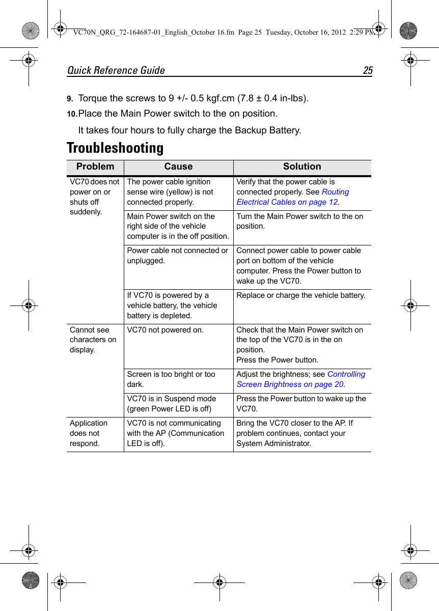
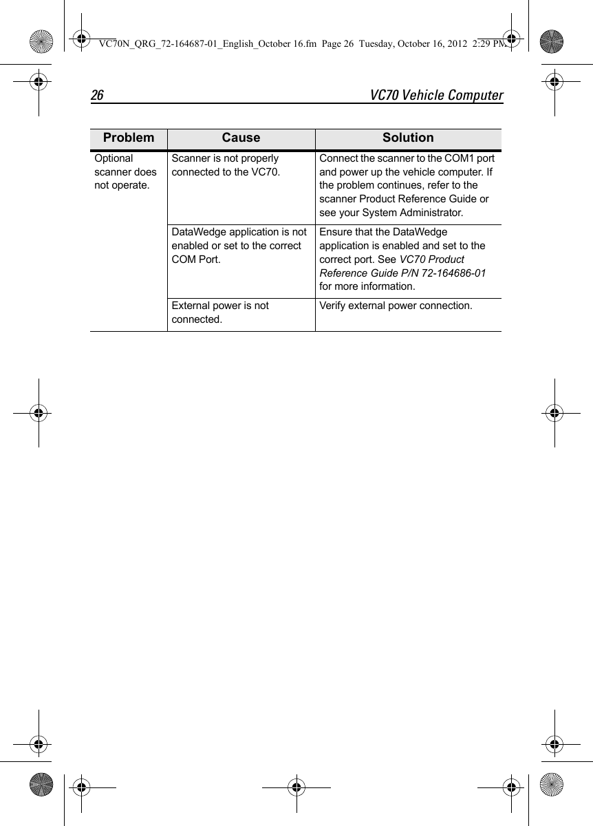
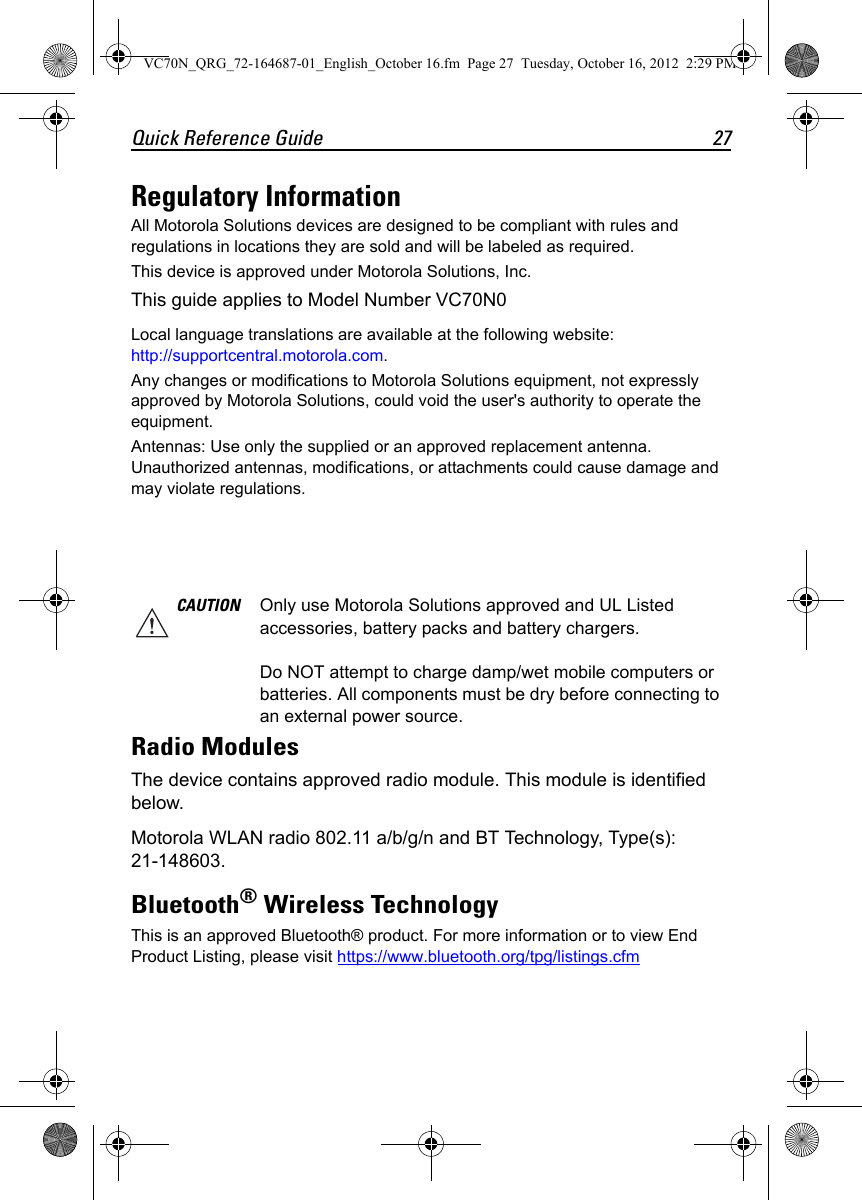
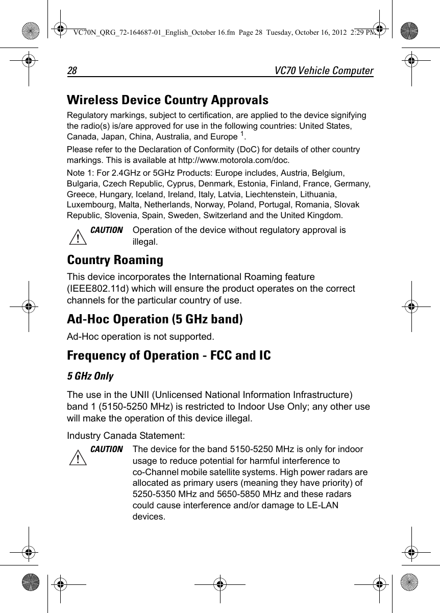
User Manual
2.
User manaul rev.pdf
User Manual
Navigation menu
Upload a User Manual
Namespaces
Wiki Guide
HTML
PDF
Info
Views
User Manual
Discussion / Help
Navigation