Zebra Technologies VC70N0 Vehicle Computer User Manual VC70N QRG 72 164687 01 English October 16
Zebra Technologies Corporation Vehicle Computer VC70N QRG 72 164687 01 English October 16
Contents
- 1. User Manual
- 2. User manaul rev.pdf
User Manual
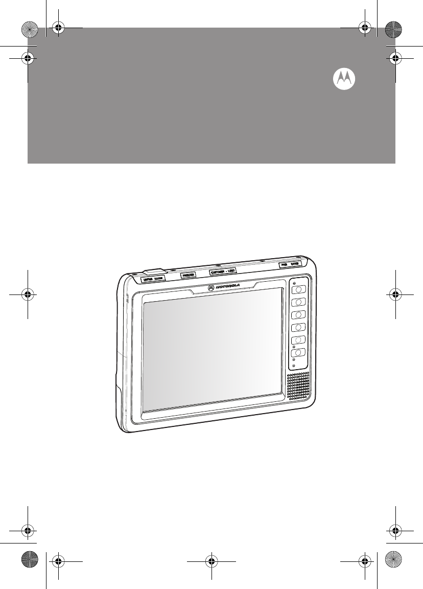
VC70N0 Vehicle Computer
Quick Reference Guide
VC70N_QRG_72-164687-01_English_October 16.fm Page 1 Tuesday, October 16, 2012 2:29 PM
2 VC70 Vehicle Computer
© 2012 MOTOROLA SOLUTIONS, INC. All rights reserved.
Motorola reserves the right to make changes to any product to improve
reliability, function, or design.
Motorola does not assume any product liability arising out of, or in
connection with, the application or use of any product, circuit, or
application described herein.
No license is granted, either expressly or by implication, estoppel, or
otherwise under any patent right or patent, covering or relating to any
combination, system, apparatus, machine, material, method, or process
in which Motorola products might be used. An implied license exists only
for equipment, circuits, and subsystems contained in Motorola products.
MOTOROLA, MOTO, MOTOROLA SOLUTIONS and the Stylized M
Logo are trademarks or registered trademarks of Motorola Trademark
Holdings, LLC and are used under license. All other trademarks are the
property of their respective owners.
Motorola Solutions, Inc.
One Motorola Plaza
Holtsville, N.Y. 11742-1300, USA
http://www.motorolasolutions.com
Warranty
Subject to the terms of Motorola’s hardware warranty statement, the
VC70 Vehicle Computer products are warranted against defects in
workmanship and materials for a period of one year from the date of
shipment. For the complete Motorola hardware product warranty
statement, go to: http://www.motorolasolutions.com/warranty.
VC70N_QRG_72-164687-01_English_October 16.fm Page 2 Tuesday, October 16, 2012 2:29 PM
Quick Reference Guide 3
Introduction
The VC70 is Motorola’s ultra-rugged forklift mounted computer. It is
designed to maximize productivity in harsh environments. Its rugged
construction and high-performance wireless networking enables
real-time data access and collection in a wide range of environments —
from the loading dock and freezer to the warehouse.
The VC70’s compact design improves visibility and reduces safety
concerns while retaining large screen size (10.4”). Its 802.11 a/b/g/n
WLAN provides real-time information that improves decision making,
reduces errors, and enhances productivity. Its rugged design with
integrated shock-mount and MIL-STD 810 military rating for shock and
vibration ensures dependable operation in challenging environments. Its
IP66 sealing, display, defroster and wide temperature range ensure
operation in and out of -30oC freezer storage warehouse.
With its high-resolution and high-brightness display, the VC70 provides
the user access to more information in low ambient light warehouse and
outdoors.
The VC70 accessories allow backward compatibility with the VC5090 for
easy and gradual migration.
About This Guide
This guide contains the following:
•Features on page 4
•Unpacking on page 5
•Installation on page 5
•Powering the VC70 On/Off on page 18
•Connecting Accessories on page 22
•Maintenance on page 22
•Troubleshooting on page 25
•Regulatory Information on page 27.
For more information including installation instructions, refer to the VC70
Product Reference Guide, p/n 72-164686-01 available at
http://supportcentral.motorola.com.
VC70N_QRG_72-164687-01_English_October 16.fm Page 3 Tuesday, October 16, 2012 2:29 PM
4 VC70 Vehicle Computer
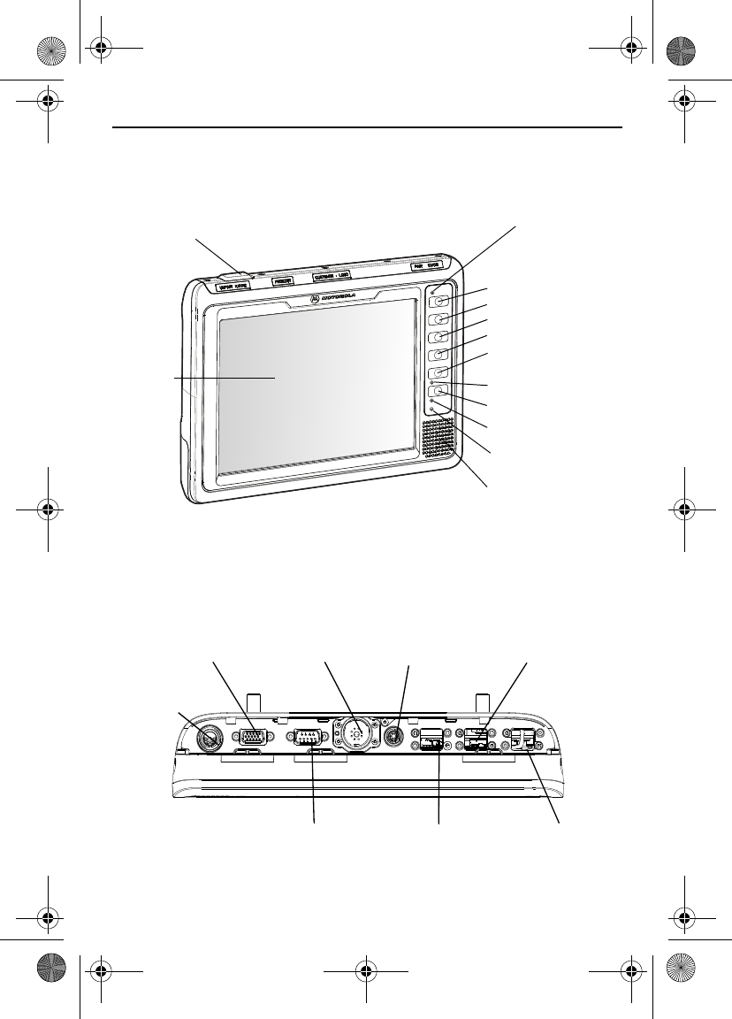
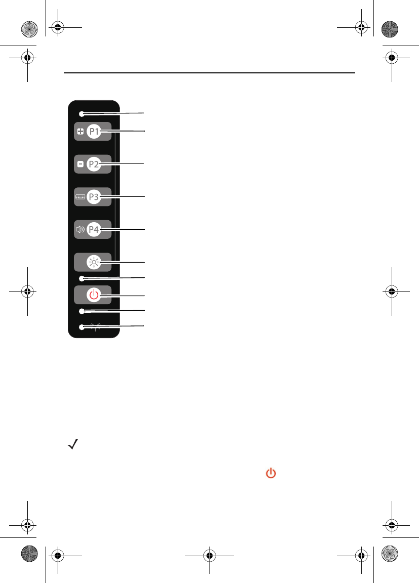
Features
Antenna Port for
Optional External
Antenna
Display
Internal Speaker
COMM LED
Charging LED
Power Button
Function LED
Brightness Key
Speaker, P4 Key
Keyboard, P3 Key
-, P2 Key
+, P1 Key
Ambient Light Sensor
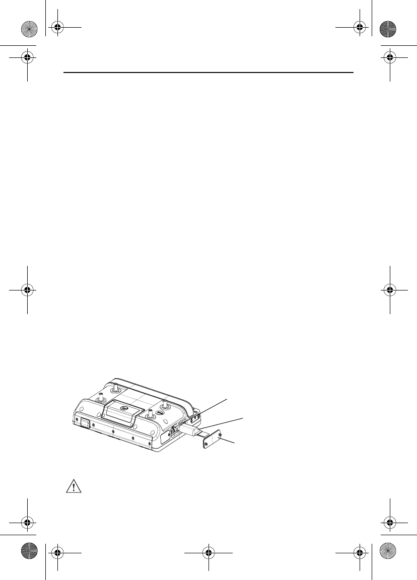
Power
COM2 + CAN-bus
COM1
Microphone External Speaker
Ethernet
USB 1
USB 2
Bottom Connectors
VC70N_QRG_72-164687-01_English_October 16.fm Page 4 Tuesday, October 16, 2012 2:29 PM
Quick Reference Guide 5
Unpacking
The following items are contained in the box:
• VC70 vehicle computer
• this guide.
Optional Accessories
• Scanners (corded and wireless) and scanner cables
• External speaker
• DC and AC power supplies and cables
• External keyboards - QWERTY, AZERTY or numeric with mounting
kits
Installation
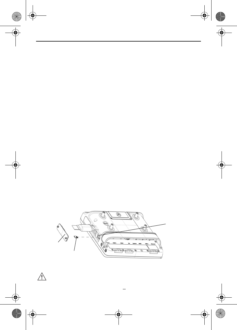
Installing a Micro SD Card
A micro SD (Secure Digital) card provides secondary non-volatile
storage. The card holder is located on the right side of the VC70 under
the Service door.
To install a micro SD card:
1. Open the two screws securing the Service door.
2. Push the memory card, with the contacts up, into the card slot until it
locks.
3. Replace the Service door and secure using two captive screws.
4. Torque the torx head screws to 4.0 + 10% kgf-cm (3.5 ± 10% lbs-in).
CAUTION Ensure to torque the screws to seal the device properly.
Otherwise, sealing can be compromised.
Service Door
Micro SD Card
Memory Card
Slot
VC70N_QRG_72-164687-01_English_October 16.fm Page 5 Tuesday, October 16, 2012 2:29 PM
6 VC70 Vehicle Computer
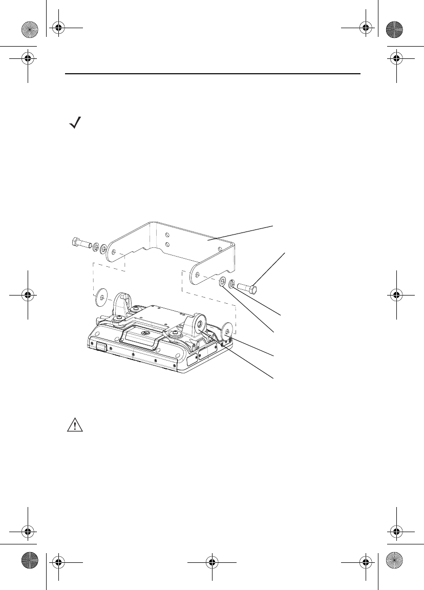
U Mount Installation
Assemble the U mount bracket onto the vehicle computer as shown
below.
Torque the M12x40mm hex head screws to 350 ± 10% kgf-cm (300 ±
10% lbs-in).
Installing the VC70 on a Forklift
Follow the instructions below to properly install the VC70 on a forklift.
• Determine the best location for mounting the vehicle computer taking
into consideration the driver’s field of view and ease of accessing the
vehicle computer.
• Install the appropriate mounting hardware. The VC70 ships with four
No. 8 Allen head screws (M10x50mm) for securing the mounting
NOTE The vehicle computer and bracket must be firmly secured to a
surface that can support the vehicle computer’s weight.
CAUTION A qualified engineer must perform the installation in a
vehicle. Improper installation can injure the operator or
damage the vehicle and/or VC70.
U Mount
Lock Washer
Flat Washer
Friction Pad
Hex Head Screw
Friction Pad
Mounting Area
VC70N_QRG_72-164687-01_English_October 16.fm Page 6 Tuesday, October 16, 2012 2:29 PM
Quick Reference Guide 7
bracket. If the supplied cap screws are not long enough, use M10 - X
stainless steel Allen head screws where X represents the length in
millimeters of the required screws.
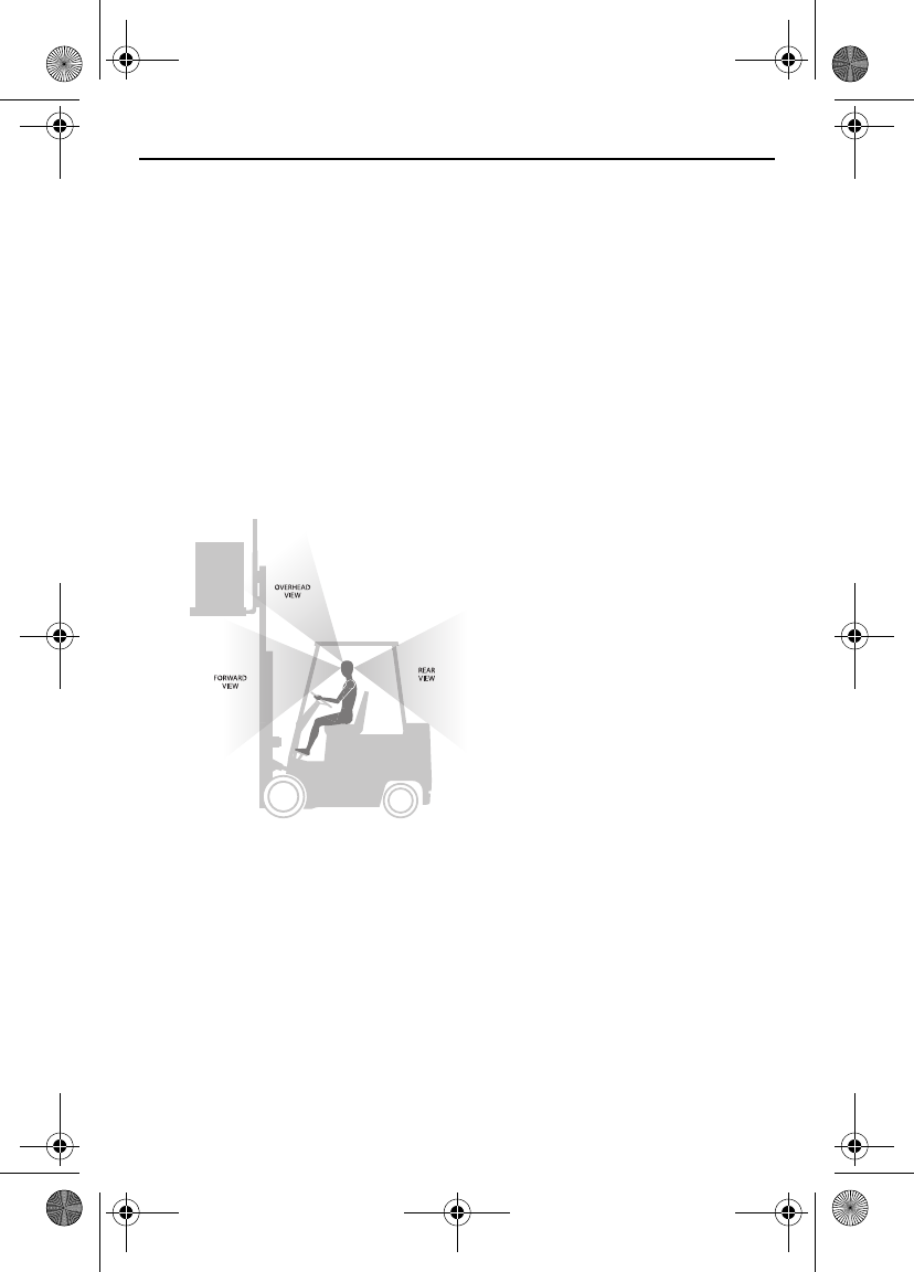
Positioning the Vehicle Computer
• Position the vehicle computer to ensure proper ventilation around the
device.
• Determine the best position for the vehicle computer and all the
associated components. If a similar vehicle computer was previously
installed, check to see if the position it used is suitable for the VC70.
• Test the installation for at least 30 minutes before installing on another
vehicle:
-Check that the position of the
vehicle computer does not
adversely obstruct vehicle
controls.
-Check that the vehicle
computer does not adversely
obstruct the driver's view.
-Check the position of the
vehicle computer for user
comfort over long periods.
-Check positioning to avoid
extreme wrist angles that may
cause injury.
VC70N_QRG_72-164687-01_English_October 16.fm Page 7 Tuesday, October 16, 2012 2:29 PM
8 VC70 Vehicle Computer
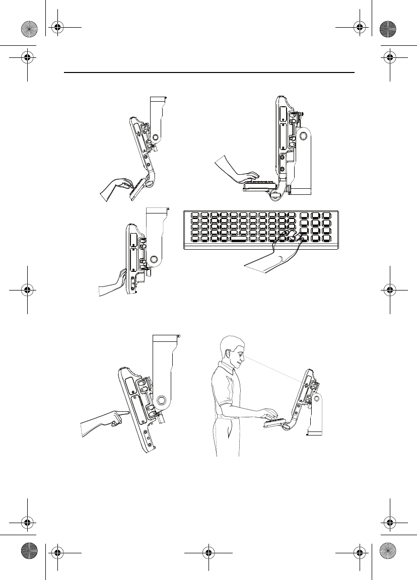
Avoid Extreme Wrist Angles
Optimum Wrist Position
VC70N_QRG_72-164687-01_English_October 16.fm Page 8 Tuesday, October 16, 2012 2:29 PM
Quick Reference Guide 9
Mounting the Vehicle Computer
Forklifts tend to generate very large shock and vibration pulses due to the
hydraulics and the lack of suspension coupled with (usually) very hard wheels.
The mounting bracket provided with the VC70 is designed as an isolator. In order
for it to be effective, the bracket base must be securely mounted to a rigid and
strong structure that fully supports the entire base of the bracket.
Most forklifts have a very rigid and durable chassis and outer body panels but top
facing surfaces may be sheet metal or plastic. These thin sheet metal or plastic
surfaces are not suitable for mounting surfaces due to their non-rigid nature.
Important Fixing Information
• Mounting surface must be flat and stiff and it must extend evenly for
the entire length of the mounting bracket surface.
• All four mounting holes must be used.
• All nuts and bolts must be checked periodically and tightened if
required.
• When installing the vehicle computer, care must be taken to ensure
that the mounting bracket footprint is fully supported. Additional plates
may be required to achieve this.
Mounting Bracket Template
Refer to the VC70N0 Product Reference Guide P/N 72-164686-01 for
mounting template.
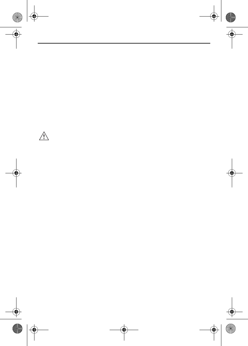
Mounting onto an Over-Head Cross-Beam Example
The diagram below illustrates a typical installation where the vehicle
computer is mounted onto a cross-beam.
CAUTION Any modification to supplied mounting bracket could cause
failure of the unit and/or mountings.
VC70N_QRG_72-164687-01_English_October 16.fm Page 9 Tuesday, October 16, 2012 2:29 PM
10 VC70 Vehicle Computer
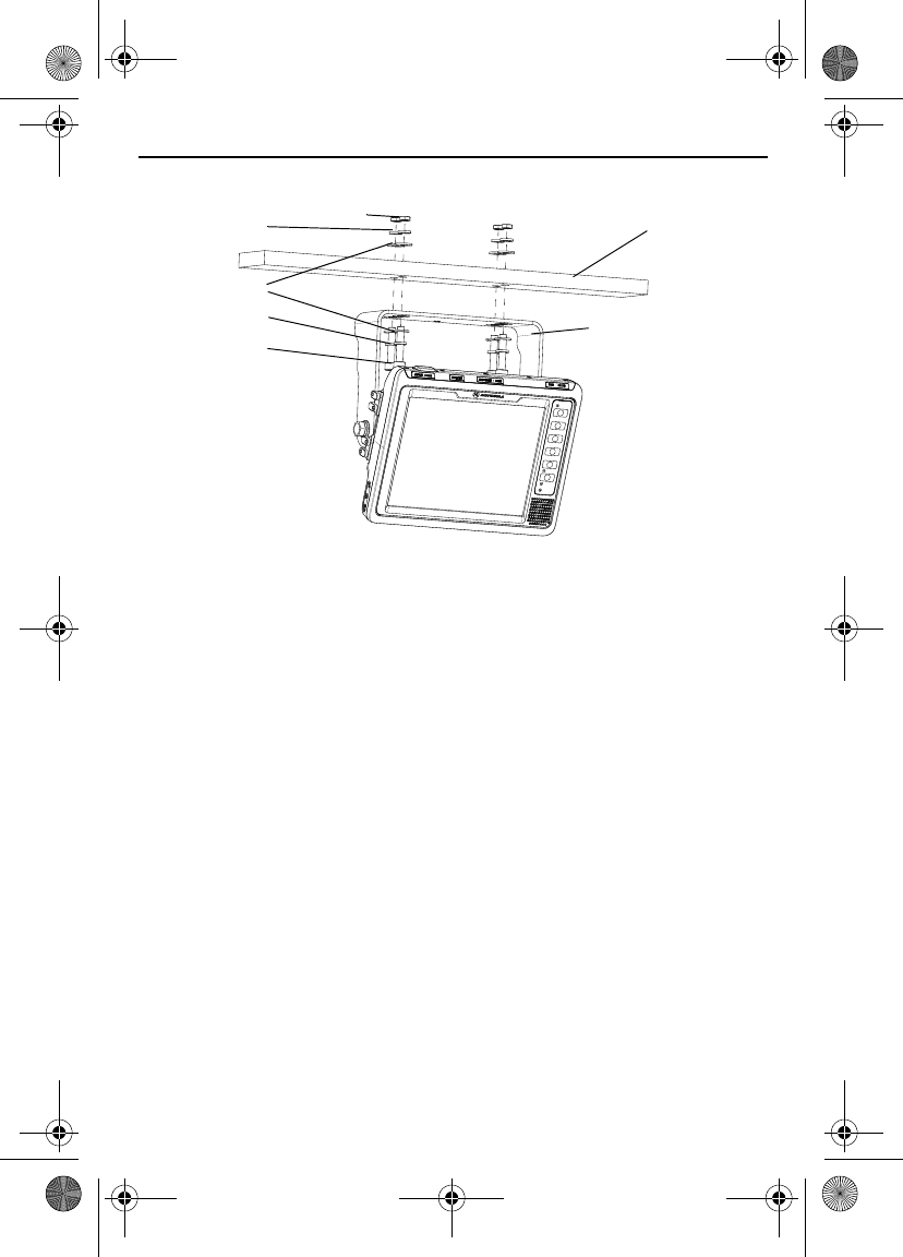
Mounting onto an Over-Head Cage Example
The diagrams below illustrates a typical installation where the vehicle
computer is mounted on an overhead cage. A customer supplied
mounting plate must be used that can withstand the weight of the vehicle
computer under vibration and shock. The plate must be made of
stainless steel or hardened steel with the following dimensions: 3.0 in.
(76.0 mm) wide, 8.66 in. (220.0 mm) long and 0.2 in. (5.0 mm) thick. The
mounting plate must be secured with hardware or to the underside of the
cage by welding.
Nuts
Lock Washers
Allen Head
Screws
Vehicle Cross-Beam
U Mount
Flat Washers
Lock Washers
VC70N_QRG_72-164687-01_English_October 16.fm Page 10 Tuesday, October 16, 2012 2:29 PM
Quick Reference Guide 11
Mounting on Flat Overhead Beams
Mounting on Transverse Overhead Beams
Customer Supplied
Mounting Plate
Nuts
Lock Washers
Allen Head
Screws
U Mount
Flat Washers
Flat Washers
Lock Washers
Customer Supplied
Mounting Plate
Welded to Beams
Nuts
Lock Washers
Allen Head
Screws
U Mount
Flat Washers
Flat Washers
Lock Washers
VC70N_QRG_72-164687-01_English_October 16.fm Page 11 Tuesday, October 16, 2012 2:29 PM
12 VC70 Vehicle Computer
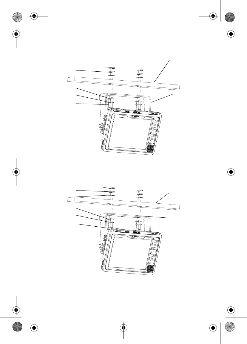
Mounting on a Dashboard or Horizontal Surface Example
The diagram below illustrates a typical installation where the vehicle
computer is mounted on a dashboard or horizontal flat surface.
Routing Electrical Cables
• Establish a neat route for the cable, staying clear of moving parts or
hot surfaces whenever possible.
• Fix the cable to existing cable runs inside the vehicle using cable ties,
but make sure they are away from any moving or hot surfaces.
• When the cabling must go through a panel, use a suitable gland.
• When fixing the conduit or cable on the outside of a vehicle, use
P-Clips. Either drill and tap the hole or use a nut and bolt to secure the
clip.
• Ensure the cable does not have tight bends. The minimum
recommended radius is 63.5mm (2.5"). Do not allow the power cable
to bend against mounting hardware. Use the optional right angled DC
power cable.
• Ensure cables do not swing or chafe on the structure. This often
requires using cable ties approximately every foot, and ensuring the
cables do not flex often, especially where they connect to the VC70.
However, if you must re-position the VC70 occasionally, ensure there
CAUTION If mounting to a thin surface, a reinforcing plate is required.
Nuts
Lock Washers
Allen Head
Screws
U Mount
Mounting
Surface
Flat Washers
Flat Washers
Lock Washers
VC70N_QRG_72-164687-01_English_October 16.fm Page 12 Tuesday, October 16, 2012 2:29 PM
Quick Reference Guide 13
is enough slack in the cable to accommodate movement without
putting tension on the cable.
• DO NOT wind a cable in and out of the mesh on a cage.
• On electric vehicles, take the power from as close to the battery as
possible, but not directly from the battery terminals, and not before
any main fuse.
• On gasoline, diesel or propane vehicles, take the power from as close
to the battery terminals as possible, and avoid using existing wiring.
• Ensure that all fuses are as close as possible to the power source.
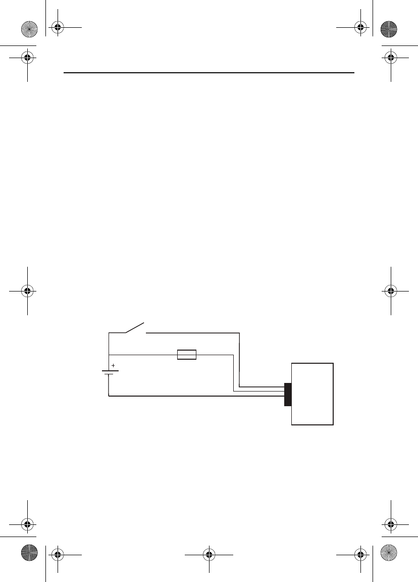
Internal Combustion Engine Forklifts
• All power wiring must use the supplied power cable.
• Fuses:
-one 3AB, 15A, 250V, FST BLO fuse - 9-60V DC
-one 3AB, 6A, 250V, FST BLO fuse - 36-96V DC.
• Keep the path between the battery and the vehicle computer as short
as possible, and away from any part of the ignition high tension
system.
You can use your old VC5090 power cable. When employing this option,
use VC5090 Bridge Cable, PN 25-159553-01. You must also replace the
fuses on the red and black wires of the old cable with the new fuses
supplied with the bridge cable kit.
VC70
15A Fuse 9-60V DC
6A Fuse 36-96V DC
Ignition Switch
Power Cable
25-15951-01
9-60V DC
25-15951-02
36-96V DC
Red
Yellow
Black
Important: If your vehicle is not equipped with
an ignition switch, connect the yellow wire
directly to the vehicle’s positive source. Failure to
comply, will not enable the computer operation.
Vehicle
Battery
VC70N_QRG_72-164687-01_English_October 16.fm Page 13 Tuesday, October 16, 2012 2:29 PM
14 VC70 Vehicle Computer
Electric Forklifts
Connecting the Power Cable
1. Disconnect the vehicle battery.
2. Connect the red wire to the vehicle's positive power source. Connect
the black wire to the vehicle's negative power source.
3. Connect the yellow wire to the vehicle's positive power source.
4. Ensure the wiring connections created are sufficiently insulated from
each other.
5. Re-connect the vehicle battery.
6. Connect the power cable connector into the vehicle computer's Power
port.
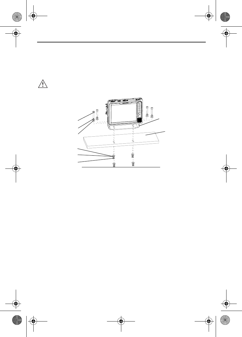
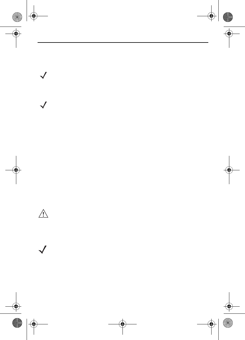
Installing the VC70 on a Cart, a Wall, or a Desktop
To mount the vehicle computer on a cart, a wall, or a desktop:
1. Install the mounting bracket to the desktop using four cap screws,
eight washers and four nuts.
NOTE See the vehicle Owner's Manual for specific wiring
information.
NOTE See the vehicle Owner's Manual for specific wiring
information.
CAUTION If mounting to a thin surface such as drywall or plywood, a
reinforcing plate is required.
NOTE The VC70 ships with four No. 8 Allen head screws
(M10x50mm) for securing the mounting bracket. If the
supplied cap screws are not long enough, use M10 - X
stainless steel Allen head screws where X represents the
length in millimeters of the required screws.
VC70N_QRG_72-164687-01_English_October 16.fm Page 14 Tuesday, October 16, 2012 2:29 PM
Quick Reference Guide 15
2. Insert the DC power cable into the DC connector on the universal
power supply.
3. Plug the other end of the cable into the vehicle computer’s power port.
4. Insert the AC line cord into the AC connector on the universal power
supply.
5. Plug the other end of the AC power cable into a wall outlet.
NOTE When using the optional AC power supply, the vehicle
computer operating temperature range is 50°F to 104°F (10°C
to 40°C).
Nuts
Lock Washers
Allen Head
Screws U Mount
Mounting
Surface
Flat Washers
Flat Washers
Lock Washers
DC Power Cable
(25-71920-01R)
Universal Power Supply
(PWRS-14000-241R
)
AC Line Cord (3-wire grounded)
Power Port
VC70N_QRG_72-164687-01_English_October 16.fm Page 15 Tuesday, October 16, 2012 2:29 PM
16 VC70 Vehicle Computer
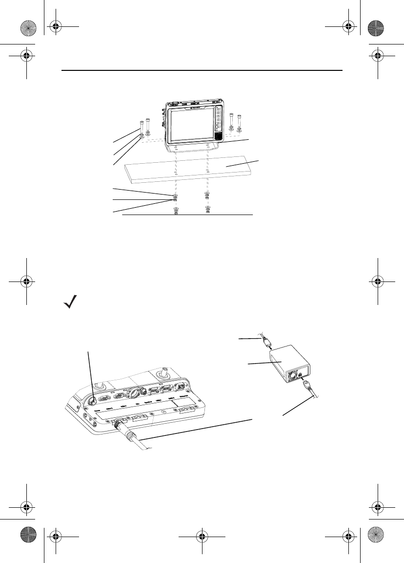
Installing the Optional QWERTY/AZERTY Keyboard
The keyboard kit contains the following items:
• keyboard
• right and left mounting arms
• four torx head screws with flat and lock washers
• six screws with captive flat and lock washers (for keyboard fastening)
• two locking knobs, two flat washers and two lock washers.
1. Position the keyboard on the tray and fasten six M4x10mm screws.
2. Attach the left and right mounting arms to both sides of the VC70,
using the M5x14mm torx head screws with flat and lock washers. Only
tighten the cap screws three turns.
Keyboard
Tray
6 Screws with
captive washers
Locking Knob
Left Mounting Arm
Torx Head Screws
with Flat and Lock
Washers
Lock Washer
Flat Washer
VC70N_QRG_72-164687-01_English_October 16.fm Page 16 Tuesday, October 16, 2012 2:29 PM
Quick Reference Guide 17
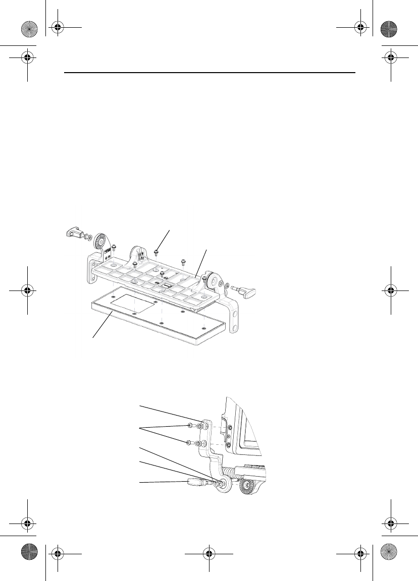
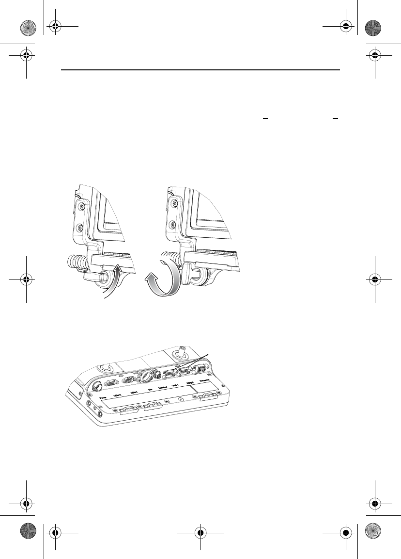
3. Insert the keyboard locking knobs through the washers and brackets
and screw into the keyboard tray. Tighten fully to lock into place.
4. Torque the mounting arms torx head screws to 40 + 10% kgf-cm (35 +
10% lbs-in).
5. To adjust keyboard tray position, loosen the right and left locking
knobs two full turns and rotate the keyboard tray to the desired
position. The keyboard tray snaps into possible positions as it is
rotated.
6. Tighten the keyboard tray locking knobs to secure the tray in position.
7. Plug the keyboard cable into one of the USB connectors and carefully
screw the locking screws using a flat head screw driver.
USB Connector
VC70N_QRG_72-164687-01_English_October 16.fm Page 17 Tuesday, October 16, 2012 2:29 PM
18 VC70 Vehicle Computer
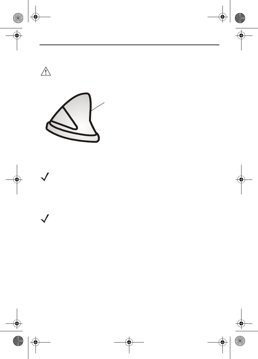
Installing the External Roof-mounted Antenna
For general antenna installation instructions refer to the Installation
Guide supplied with the antenna.
Powering the VC70 On/Off
To power on, place the Main Power switch on the top of the VC70 to the
on ( | ) position.
To power off, place the Main Power switch on the top of the VC70 to the
off ( O ) position.
WARNING!The antenna must be installed in a location that will ensure
a distance of at least 8” (20cm) between the antenna and
any bystander.
IMPORTANT If not installed on a metal roof, the antenna must
be installed in the middle of a flat metal surface (minimum
size 2.56” (65 mm)x2.56” (65 mm)).
NOTE Only use the Main Power switch when removing power
completely from the VC70. The power switch cover door
can be safely removed without affecting the unit seal in case
the user prefer to switch the unit off completely.
Sharkfin Antenna
VC70N_QRG_72-164687-01_English_October 16.fm Page 18 Tuesday, October 16, 2012 2:29 PM
Quick Reference Guide 19
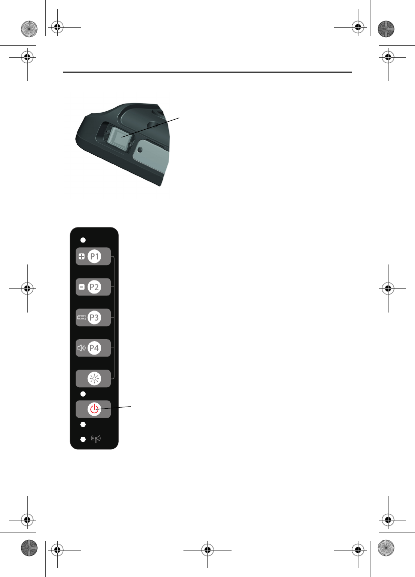
Use the Power button on the Quick Access Panel to place the VC70 into
Suspend mode or wake the VC70 from Suspend mode.
This is usually enough to conserve battery power while the VC70 is idle
during off time in normal operation.
Main Power Switch
Power Button
VC70N_QRG_72-164687-01_English_October 16.fm Page 19 Tuesday, October 16, 2012 2:29 PM
20 VC70 Vehicle Computer
Charging the Internal Backup Battery
After installing the VC70, leave it powered on for 6 hours to fully charge
the internal backup battery. Note that the VC70 can charge the backup
battery while in Suspend mode, but not if power is turned Off with the
power switch.
The internal battery provides up to 30 minutes of VC70 operation with
reduced functionality (no heaters, USB, Serial, Ethernet, external
speaker interfaces and dimmed display backlight, and lower internal
speaker volume) to enable forklift battery replacement when drained.
Backup battery will also maintain the RAM memory for 72 hours when
fully charged. The data in the Flash memory or Flash file system is not
affected by the state of charge.
Calibrating the Touch Screen
The VC70 prompts you to calibrate the touch screen when you first
power on the VC70 or after a cold-boot.
1. Carefully touch and hold the center of each target. Repeat as the
target moves around the screen.
2. Tap the screen to accept the settings when the calibration is complete.
Controlling Screen Brightness
There are five levels of screen brightness. To adjust the brightness of the
screen, press the Brightness button on the Quick Access Panel. The
amber Function LED lights indicating that the VC70 is in the backlight
control mode. Press the P1 (+) button to increase the brightness or the
P2 (-) button to decrease the brightness. Press the Brightness ( )
button to exit this mode (or after five seconds of inactivity the VC70
automatically returns to normal operation).
CAUTION Do not use sharp objects when touching the screen. Use
your finger tip or a stylus when touching the screen.
VC70N_QRG_72-164687-01_English_October 16.fm Page 20 Tuesday, October 16, 2012 2:29 PM
Quick Reference Guide 21
Resetting the Vehicle Computer
If the vehicle computer stops responding to inputs, perform a warm boot
or cold boot.
Performing a Warm Boot
A warm boot restarts the vehicle computer and saves all stored records
and entries.
To perform a warm boot, press the Power button ( ) on the Quick
Access Panel continuously for 5 seconds.
NOTE Verify that all open files are closed. Files that remain open
during a warm boot may not be retained.
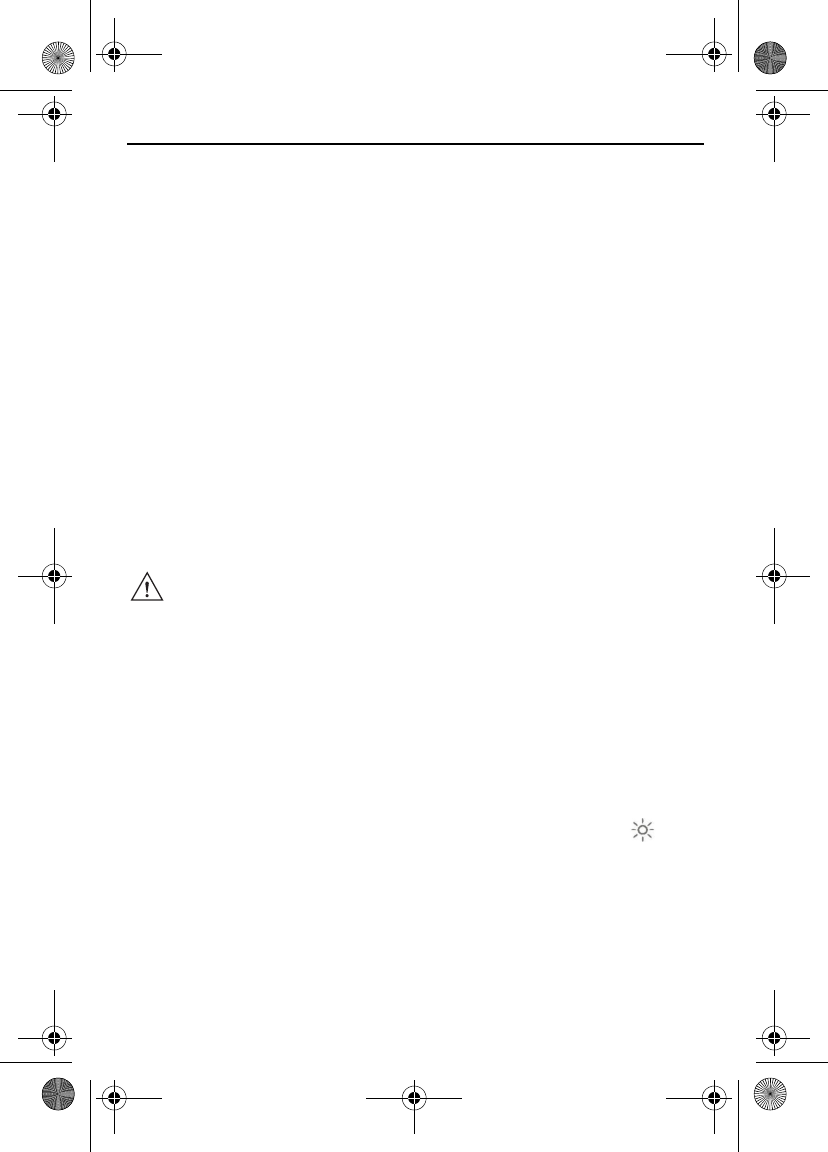
-, P2 Button
+, P1 Button
Keyboard, P3 Button
Speaker, P4 Button
COMM LED
Charging LED
Power Button
Function LED
Brightness Key
Ambient Light Sensor
VC70N_QRG_72-164687-01_English_October 16.fm Page 21 Tuesday, October 16, 2012 2:29 PM
22 VC70 Vehicle Computer
Performing a Cold Boot
A cold boot restarts the vehicle computer, but erases all stored records
and entries in RAM. Data saved in flash memory or a memory card is not
lost. In addition it returns formats, preferences and other settings to the
factory default settings. There are two ways to perform a cold boot:
• Simultaneously press and hold the Power, P1 and P3 buttons.
• Turn off the Main Power switch on the right side of the vehicle
computer, press the Power, P1 and P3 buttons simultaneously then
turn the Main Power switch to the on position.
Programmable Keys
The programmable keys on the Quick Access Panel (P1, P2, P3, P4)
can be set to perform certain functions, such as switching between
applications or emulator sessions.
To set a programmable key:
1. From the Start menu, select Settings > Control Panel.
2. Select the Programmable Keys icon.
3. In the Key: drop-down list, select the key to program.
4. In the Action drop-down list, select the function to assign to the key to
perform.
5. Tap OK.
Connecting Accessories
Connect an optional scanner, ActiveSync serial or USB cable, audio or
USB device using the appropriate connector on the bottom of the VC70.
Cables are available from Motorola.
You may also use the USB port for ActiveSync connection, if the serial
ports are used for another purpose. This cable is also available from
Motorola. Refer to the VC70 Product Reference Guide, P/N
72-164686-01 for information about additional accessories.
Maintenance
The vehicle computer is factory-sealed. There are 3 user accessible
areas:
VC70N_QRG_72-164687-01_English_October 16.fm Page 22 Tuesday, October 16, 2012 2:29 PM
Quick Reference Guide 23
• Service door - provides access to the micro USB On-The-Go for
ActiveSync without the need to disconnect any accessory, access to
the Micro SD card slot and access to the desiccant.
• Access to the On/Off switch (the door can be removed without
affecting the sealing).
• Access to the backup battery.
For general cleaning:
• Clean the casing, keyboard, and display window by wiping with a soft
cloth. Use a damp cloth if necessary.
• Never use solvents or abrasive cleaners. You may damage the
display or keyboard.
Replacing the Desiccant Bag
1. The VC70 ships with a desiccant bag installed. The installer may wish
to replace the desiccant in the VC70 with a new bag prior to installing
the VC70 on the vehicle, as transit and storage may have saturated
the desiccant.
2. Open the two screws securing the service door and remove the door.
3. Pull out the old dessicant bag.
4. Open the new desiccant package and remove the desiccant bag.
5. Fold the four corners of the bag under to form a pillow.
6. Place the desiccant bag in the desiccant well.
7. Carefully place the service door onto the right side of the housing.
8. Torque the torx head screws to 4.0 + 10% kgf-cm (3.5 ± 10% lbs-in).
CAUTION Be sure to torque the screws to seal the device properly.
Otherwise, sealing can be compromised.
Desiccant Bag
Service Door
Desiccant Well
VC70N_QRG_72-164687-01_English_October 16.fm Page 23 Tuesday, October 16, 2012 2:29 PM
24 VC70 Vehicle Computer
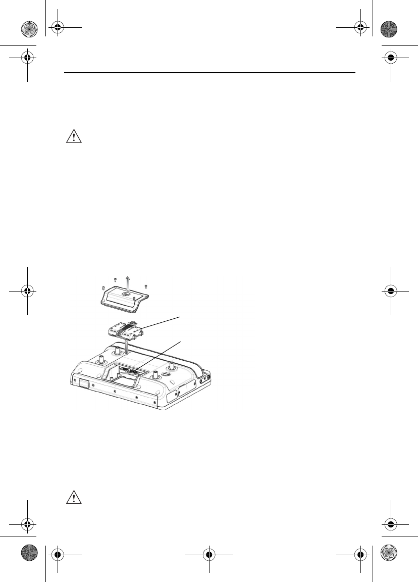
Replacing the Backup Battery
To replace the backup battery:
1. Place the Main Power switch on the right side of the vehicle computer
to the off position and perform cold boot to electrically disconnect the
battery from the unit.
2. Open the four screws securing the Backup Battery door on the back of
the vehicle computer and remove the door.
3. Open the four screws securing the Backup Battery and disconnect the
Backup Battery connector.
4. Carefully pull the Backup Battery out of the computer.
5. Place the new backup battery into the well.
6. Connect the Backup Battery connector to the connector inside the
Backup Battery well.
7. Secure the battery into location using four screws.
8. Place the Backup Battery door over the battery and secure using the
four captive screws.
CAUTION Use ESD precautions when installing the backup
battery.
CAUTION Be sure to torque the screws to seal the device properly.
Otherwise, sealing can be compromised.
Backup Battery
Connector
Backup Battery
VC70N_QRG_72-164687-01_English_October 16.fm Page 24 Tuesday, October 16, 2012 2:29 PM
Quick Reference Guide 25
9. Torque the screws to 9 +/- 0.5 kgf.cm (7.8 ± 0.4 in-lbs).
10.Place the Main Power switch to the on position.
It takes four hours to fully charge the Backup Battery.
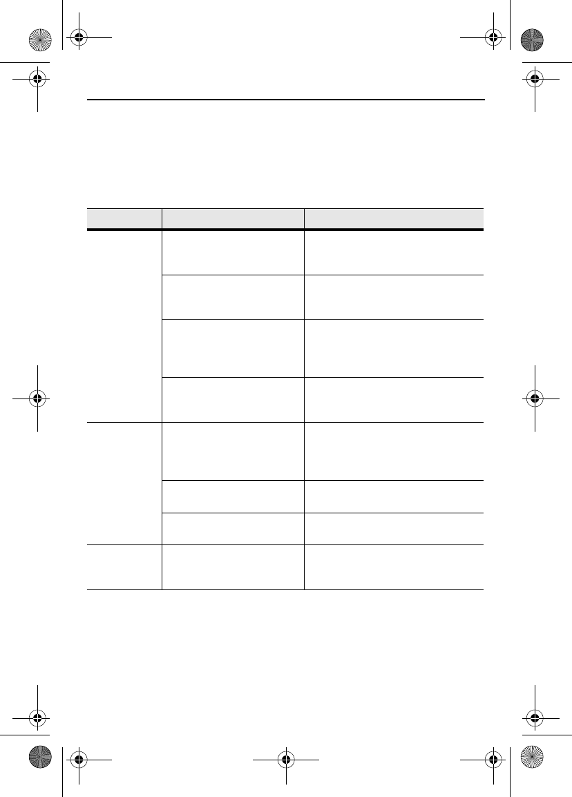
Troubleshooting
Problem Cause Solution
VC70 does not
power on or
shuts off
suddenly.
The power cable ignition
sense wire (yellow) is not
connected properly.
Verify that the power cable is
connected properly. See
Routing
Electrical Cables on page 12
.
Main Power switch on the
right side of the vehicle
computer is in the off position.
Turn the Main Power switch to the on
position.
Power cable not connected or
unplugged.
Connect power cable to power cable
port on bottom of the vehicle
computer. Press the Power button to
wake up the VC70.
If VC70 is powered by a
vehicle battery, the vehicle
battery is depleted.
Replace or charge the vehicle battery.
Cannot see
characters on
display.
VC70 not powered on. Check that the Main Power switch on
the top of the VC70 is in the on
position.
Press the Power button.
Screen is too bright or too
dark.
Adjust the brightness; see
Controlling
Screen Brightness on page 20
.
VC70 is in Suspend mode
(green Power LED is off)
Press the Power button to wake up the
VC70.
Application
does not
respond.
VC70 is not communicating
with the AP (Communication
LED is off).
Bring the VC70 closer to the AP. If
problem continues, contact your
System Administrator.
VC70N_QRG_72-164687-01_English_October 16.fm Page 25 Tuesday, October 16, 2012 2:29 PM
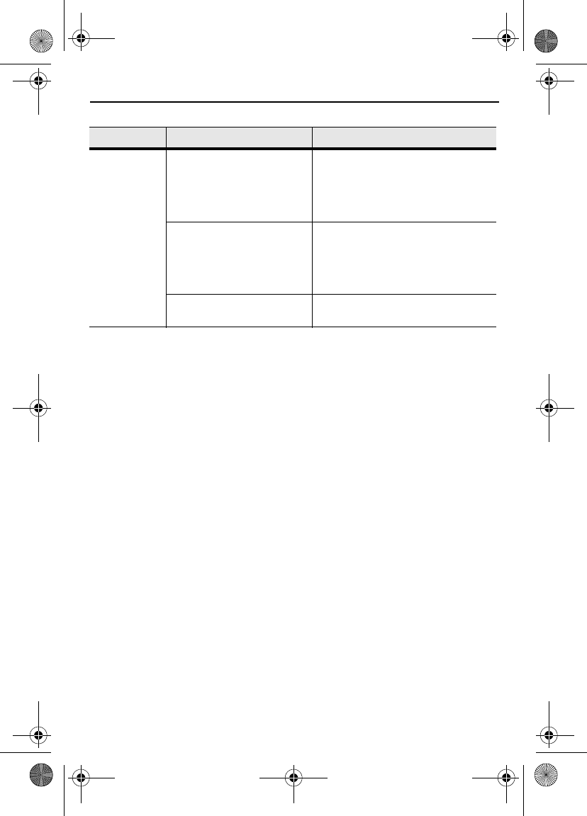
26 VC70 Vehicle Computer
Optional
scanner does
not operate.
Scanner is not properly
connected to the VC70.
Connect the scanner to the COM1 port
and power up the vehicle computer. If
the problem continues, refer to the
scanner Product Reference Guide or
see your System Administrator.
DataWedge application is not
enabled or set to the correct
COM Port.
Ensure that the DataWedge
application is enabled and set to the
correct port. See VC70 Product
Reference Guide P/N 72-164686-01
for more information.
External power is not
connected.
Verify external power connection.
Problem Cause Solution
VC70N_QRG_72-164687-01_English_October 16.fm Page 26 Tuesday, October 16, 2012 2:29 PM
Quick Reference Guide 27
Regulatory Information
All Motorola Solutions devices are designed to be compliant with rules and
regulations in locations they are sold and will be labeled as required.
This device is approved under Motorola Solutions, Inc.
This guide applies to Model Number VC70N0
Local language translations are available at the following website:
http://supportcentral.motorola.com.
Any changes or modifications to Motorola Solutions equipment, not expressly
approved by Motorola Solutions, could void the user's authority to operate the
equipment.
Antennas: Use only the supplied or an approved replacement antenna.
Unauthorized antennas, modifications, or attachments could cause damage and
may violate regulations.
Radio Modules
The device contains approved radio module. This module is identified
below.
Motorola WLAN radio 802.11 a/b/g/n and BT Technology, Type(s):
21-148603.
Bluetooth
®
Wireless Technology
This is an approved Bluetooth® product. For more information or to view End
Product Listing, please visit https://www.bluetooth.org/tpg/listings.cfm
CAUTION Only use Motorola Solutions approved and UL Listed
accessories, battery packs and battery chargers.
Do NOT attempt to charge damp/wet mobile computers or
batteries. All components must be dry before connecting to
an external power source.
VC70N_QRG_72-164687-01_English_October 16.fm Page 27 Tuesday, October 16, 2012 2:29 PM
28 VC70 Vehicle Computer
Wireless Device Country Approvals
Regulatory markings, subject to certification, are applied to the device signifying
the radio(s) is/are approved for use in the following countries: United States,
Canada, Japan, China, Australia, and Europe 1.
Please refer to the Declaration of Conformity (DoC) for details of other country
markings. This is available at http://www.motorola.com/doc.
Note 1: For 2.4GHz or 5GHz Products: Europe includes, Austria, Belgium,
Bulgaria, Czech Republic, Cyprus, Denmark, Estonia, Finland, France, Germany,
Greece, Hungary, Iceland, Ireland, Italy, Latvia, Liechtenstein, Lithuania,
Luxembourg, Malta, Netherlands, Norway, Poland, Portugal, Romania, Slovak
Republic, Slovenia, Spain, Sweden, Switzerland and the United Kingdom.
Country Roaming
This device incorporates the International Roaming feature
(IEEE802.11d) which will ensure the product operates on the correct
channels for the particular country of use.
Ad-Hoc Operation (5 GHz band)
Ad-Hoc operation is not supported.
Frequency of Operation - FCC and IC
5 GHz Only
The use in the UNII (Unlicensed National Information Infrastructure)
band 1 (5150-5250 MHz) is restricted to Indoor Use Only; any other use
will make the operation of this device illegal.
Industry Canada Statement:
CAUTION Operation of the device without regulatory approval is
illegal.
CAUTION The device for the band 5150-5250 MHz is only for indoor
usage to reduce potential for harmful interference to
co-Channel mobile satellite systems. High power radars are
allocated as primary users (meaning they have priority) of
5250-5350 MHz and 5650-5850 MHz and these radars
could cause interference and/or damage to LE-LAN
devices.
VC70N_QRG_72-164687-01_English_October 16.fm Page 28 Tuesday, October 16, 2012 2:29 PM
Quick Reference Guide 29
Avertissement: Le dispositive fonctionnant dans la bande 5150-5250
MHz est réservé uniquement pour une utilisation à l'intérieur afin de
réduire les risques de brouillage préjudiciable aux systèmes de satellites
mobiles utilisant les mêmes canaux.
Les utilisateurs de radars de haute puissance sont désignés utilisateurs
principaux (c.-à-d., qu'ils ont la priorité) pour les bands 5250-5350 MHz
et 5650-5850 MHz et que ces radars pourraient causer du brouillage
et/ou des dommages aux dispositifs LAN-EL.
2.4 GHz Only
The available channels for 802.11 b/g/n operation in the US are
Channels 1 to 13. The range of channels is limited by firmware.
Health and Safety Recommendations
Ergonomic Recommendations
• Reduce or eliminate repetitive motion
•Maintain a natural position
• Reduce or eliminate excessive force
•Keep objects that are used frequently within easy reach
•Perform tasks at correct heights
• Reduce or eliminate vibration
• Reduce or eliminate direct pressure
•Provide adjustable workstations
•Provide adequate clearance
•Provide a suitable working environment
• Improve work procedures.
Vehicle Installation
RF signals may affect improperly installed or inadequately shielded electronic
systems in motor vehicles (including safety systems). Check with the
CAUTION In order to avoid or minimize the potential risk of ergonomic
injury follow the recommendations below. Consult with your
local Health & Safety Manager to ensure that you are
adhering to your company's safety programs to prevent
employee injury.
VC70N_QRG_72-164687-01_English_October 16.fm Page 29 Tuesday, October 16, 2012 2:29 PM
30 VC70 Vehicle Computer
manufacturer or its representative regarding your vehicle. You should also consult
the manufacturer of any equipment that has been added to your vehicle.
An air bag inflates with great force. DO NOT place objects, including either
installed or portable wireless equipment, in the area over the air bag or in the air
bag deployment area. If in-vehicle wireless equipment is improperly installed and
the air bag inflates, serious injury could result.
Position your device within easy reach. Be able to access your device without
removing your eyes from the road.
Warnings for Use of Wireless Devices
Please observe all warning notices with regard to the usage of wireless devices.
Potentially Hazardous Atmospheres
You are reminded of the need to observe restrictions on the use of radio devices
in fuel depots, chemical plants etc. and areas where the air contains chemicals or
particles (such as grain, dust, or metal powders) and any other area where you
would normally be advised to turn off your vehicle engine.
Hearing Aids
When some wireless devices are used near some hearing devices (hearing aids
and cochlear implants), users may detect a buzzing, humming, or whining noise.
Some hearing devices are more immune than others to this interference noise,
and wireless devices also vary in the amount of interference they generate. In the
event of interference you may want to consult your hearing aid supplier to discuss
solutions.
Hearing Aid Compatibility
This device is not HAC compliant during Voice Over IP (VOIP) calls.
Pacemakers
Pacemaker manufacturers recommended that a minimum of 15cm (6
inches) be maintained between a handheld wireless device and a
NOTE Connection to an alert device that will cause a vehicle horn to
sound or lights to flash, on receipt of a call on public roads, is
not permitted.
IMPORTANT Before installing or using, check state and local
laws regarding windshield mounting and use of equipment.
VC70N_QRG_72-164687-01_English_October 16.fm Page 30 Tuesday, October 16, 2012 2:29 PM
Quick Reference Guide 31
pacemaker to avoid potential interference with the pacemaker. These
recommendations are consistent with independent research and
recommendations by Wireless Technology Research.
Persons with Pacemakers:
• Should ALWAYS keep the device more than 15cm (6 inches) from
their pacemaker when turned ON.
•Should not carry the device in a breast pocket.
•Should use the ear furthest from the pacemaker to minimise the
potential for interference.
•If you have any reason to suspect that interference is taking place,
turn OFF your device.
Other Medical Devices
Please consult your physician or the manufacturer of the medical device, to
determine if the operation of your wireless product may interfere with the medical
device.
RF Exposure Guidelines
Safety Information
Reducing RF Exposure - Use Properly
Only operate the device in accordance with the instructions supplied.
International
The device complies with internationally recognized standards covering human
exposure to electromagnetic fields from radio devices. For information on
“International” human exposure to electromagnetic fields refer to the
Motorola/Symbol Declaration of Conformity (DoC) at
http://www.motorola.com/doc
Europe
To satisfy EU RF exposure requirements, a mobile transmitting device must
operate with a minimum separation distance of 20cm or more from a person’s
body.
Remote and Standalone Antenna Configurations
To comply with EU RF exposure requirements, antennas that are mounted
externally at remote locations or operating near users at stand-alone desktop of
VC70N_QRG_72-164687-01_English_October 16.fm Page 31 Tuesday, October 16, 2012 2:29 PM
32 VC70 Vehicle Computer
similar configurations must operate with a minimum separation distance of 20 cm
from all persons.
US and Canada
Co-located Statement
To comply with FCC RF exposure compliance requirement, the antenna used for
this transmitter must not be co-located or operating in conjunction with any other
transmitter/antenna except those already approved in this filling.
Industry Canada Statement
IMPORTANT NOTE: Radiation Exposure Statement:
This equipment complies with IC radiation exposure limits set forth for
uncontrolled environment. This equipment should be installed and operated with
minimum distance 20cm between the radiator and your body.
NOTE IMPORTANTE:
Déclaration d'exposition aux radiations:
Cet équipement est conforme aux limites d'exposition aux rayonnements IC
établies pour un environnement non
contrôlé. Cet équipement doit être installé et utilisé avec un minimum de 20 cm de
distance entre la source de
rayonnement et votre corps.
Remote and Standalone Antenna Configurations
To comply with FCC RF exposure requirements, antennas that are mounted
externally at remote locations or operating near users at stand-alone desktop of
similar configurations must operate with a minimum separation distance of 20 cm
from all persons.
To satisfy FCC RF exposure requirements, a mobile transmitting device must
operate with a minimum separation distance of 20 cm or more from a person's
body.
Power Supply
Use ONLY a LISTED Motorola, Type no. PWRS-14000 (12Vdc, 9A),
PWRS-9-60VDC (12Vdc, 9A) power supply, marked Class 2 or LPS (IEC60950-1,
SELV). Use of alternative Power Supply will invalidate any approvals given to this
unit and may be dangerous.
Batteries
Please follow the local regulations when disposing of re-chargeable batteries.
VC70N_QRG_72-164687-01_English_October 16.fm Page 32 Tuesday, October 16, 2012 2:29 PM
Quick Reference Guide 33
Taiwan - Recycling
EPA (Environmental Protection Administration) requires dry
battery producing or importing firms in accordance with
Article 15 of the Waste Disposal Act are required to indicate
the recycling marks on the batteries used in sales, giveaway
or promotion. Contact a qualified Taiwanese recycler for
proper battery disposal.
Battery Information
Use only Motorola approved batteries. Accessories which have battery charging
capability are approved for use with the following battery models:
Motorola 82-161178-01 (3.7 Vdc, 1880mAh)
Motorola rechargeable battery packs are designed and constructed to the highest
standards within the industry.
However, there are limitations to how long a battery can operate or be stored
before needing replacement. Many factors affect the actual life cycle of a battery
pack, such as heat, cold, harsh environmental conditions and severe drops.
When batteries are stored over six (6) months, some irreversible deterioration in
overall battery quality may occur. Store batteries at half of full charge in a dry, cool
place, removed from the equipment to prevent loss of capacity, rusting of metallic
parts and electrolyte leakage. When storing batteries for one year or longer, the
charge level should be verified at least once a year and charged to half of full
charge.
Replace the battery when a significant loss of run time is detected.
Standard warranty period for all Motorola batteries is 30 days, regardless if the
battery was purchased separately or included as part of the mobile computer or
bar code scanner. For more information on Symbol batteries, please visit:
http:/mysymbolcare.symbol.com/battery/batbasics1.html.
Battery Safety Guidelines
• The area in which the units are charged should be clear of debris and
combustible materials or chemicals. Particular care should be taken
where the device is charged in a non commercial environment.
• Follow battery usage, storage, and charging guidelines found in the
user's guide.
• Improper battery use may result in a fire, explosion, or other hazard.
• To charge the mobile device battery, the battery and charger
temperatures must be between +32 ºF and +104 ºF (0 ºC and +40 ºC)
VC70N_QRG_72-164687-01_English_October 16.fm Page 33 Tuesday, October 16, 2012 2:29 PM
34 VC70 Vehicle Computer
• Do not use incompatible batteries and chargers. Use of an
incompatible battery or charger may present a risk of fire, explosion,
leakage, or other hazard. If you have any questions about the
compatibility of a battery or a charger, contact Motorola Enterprise
Mobility support.
• Do not disassemble or open, crush, bend or deform, puncture, or
shred.
• Severe impact from dropping any battery-operated device on a hard
surface could cause the battery to overheat.
• Do not short circuit a battery or allow metallic or conductive objects to
contact the battery terminals.
• Do not modify or remanufacture, attempt to insert foreign objects into
the battery, immerse or expose to water or other liquids, or expose to
fire, explosion, or other hazard.
• Do not leave or store the equipment in or near areas that might get
very hot, such as in a parked vehicle or near a radiator or other heat
source. Do not place battery into a microwave oven or dryer.
• Battery usage by children should be supervised.
• Please follow local regulations to promptly dispose of used
re-chargeable batteries.
• Do not dispose of batteries in fire.
• Seek medical advice immediately if a battery has been swallowed.
• In the event of a battery leak, do not allow the liquid to come in contact
with the skin or eyes. If contact has been made, wash the affected
area with large amounts of water and seek medical advice.
• If you suspect damage to your equipment or battery, contact Motorola
Enterprise Mobility support to arrange for inspection.
Radio Frequency Interference Requirements - FCC
Note: This equipment has been tested and found to comply with
the limits for a Class B digital device, pursuant to Part 15 of the
FCC rules. These limits are designed to provide reasonable
protection against harmful interference in a residential installation. This equipment
generates, uses, and can radiate radio frequency energy and, if not installed and
used in accordance with the instructions, may cause harmful interference to radio
communications. However there is no guarantee that interference will not occur in
a particular installation. If this equipment does cause harmful interference to radio
VC70N_QRG_72-164687-01_English_October 16.fm Page 34 Tuesday, October 16, 2012 2:29 PM

Quick Reference Guide 35
or television reception, which can be determined by turning the equipment off and
on, the user is encouraged to try to correct the interference by one or more of the
following measures:
• Reorient or relocate the receiving antenna
• Increase the separation between the equipment and receiver
• Connect the equipment into an outlet on a circuit different from that to which
the receiver is connected
• Consult the dealer or an experienced radio/TV technician for help.
Radio Transmitters (Part 15)
This device complies with Part 15 of the FCC Rules. Operation is subject to the
following two conditions: (1) this device may not cause harmful interference, and
(2) this device must accept any interference received, including interference that
may cause undesired operation.
The use of 5 GHz WLAN's (in the US), have the following restrictions:
• Notched Band 5.60 - 5.65 GHz
Radio Frequency Interference Requirements - Canada
This Class B digital apparatus complies with Canadian ICES-003. Cet appareil
numérique de la classe B est conforme à la norme NMB-003 du Canada.
Radio Transmitters
The use of 5 GHz RLAN's (in Canada), have the following restrictions:
• Restricted Band 5.60 - 5.65 GHz
This device complies with RSS 210 of Industry & Science Canada. Operation is
subject to the following two conditions: (1) this device may not cause harmful
interference and (2) this device must accept any interference received, including
interference that may cause undesired operation.
Ce dispositif est conforme à la norme CNR-210 d'Industrie Canada applicable aux
appareils radio exempts de licence. Son fonctionnement est sujet aux deux
conditions suivantes: (1) le dispositif ne doit pas produire de brouillage
préjudiciable, et (2) ce dispositif doit accepter tout brouillage reçu, y compris un
brouillage susceptible de provoquer un fonctionnement indésirable.
Label Marking: The Term “IC:” before the radio certification only signifies that
Industry Canada technical specifications were met.
To reduce potential radio interference to other users, the antenna type
and its gain should be so chosen that the equivalent isotropically
VC70N_QRG_72-164687-01_English_October 16.fm Page 35 Tuesday, October 16, 2012 2:29 PM
36 VC70 Vehicle Computer
radiated power (EIRP) is not more than that permitted for successful
communication.
Marking and European Economic Area (EEA)
The use of 2.4 GHz RLAN's (through the EEA), have the following
restrictions:
•Maximum radiated transmit power of 100 mW EIRP in the frequency range
2.400 -2.4835 GHz
Statement of Compliance
Motorola Solutions, Inc., hereby, declares that this device is in compliance with
the essential requirements and other relevant provisions of Directives 1999/5/EC.
A declaration of Conformity may be obtained from http://www.motorola.com/doc/
CAUTION This is a Class B product. In a domestic environment this
product may cause radio interference in which case the
user may be required to take adequate measures.
VC70N_QRG_72-164687-01_English_October 16.fm Page 36 Tuesday, October 16, 2012 2:29 PM
Quick Reference Guide 37
Japan (VCCI) - Voluntary Control Council for
Interference
Class B ITE
Other Countries
Australia-Use of 5 GHz RLAN's in Australia is restricted in the following band
5.50 - 5.65GHz.
Brazil-Nota: A marca de certificação se aplica ao Transceptor, modelo VC70N0.
Este equipamento opera em caráter secundário, isto é, não tem direito a proteção
contra interferência prejudicial, mesmo de estações do mesmo tipo, e não pode
causar interferência a sistemas operando em caráter primário.
Para maiores informações sobre ANATEL consulte o site: www.anatel.gov.br
Chile-Este equipo cumple con la Resolución No 403 de 2008, de la Subsecretaria
de telecomunicaciones, relativa a radiaciones electromagnéticas.
China-
Mexico- Restrict Frequency Range to: 2.450 - 2.4835 GHz.
South Korea-For a radio equipment using 2400~2483.5MHz or 5725~5825MHz,
the following two expression should be displayed;
해당 무선설비는 운용 중 전파혼신 가능성이 있음
당해 무선설비 는전파혼 신 가능성이 있으므로 인명안전과 관련된 서비스는 할 수
없습니다 .
Taiwan-
臺灣
低功率電波輻射性電機管理辦法
第十二條
VC70N_QRG_72-164687-01_English_October 16.fm Page 37 Tuesday, October 16, 2012 2:29 PM
38 VC70 Vehicle Computer
經型式認證合格之低功率射頻電機,非經許可,公司、商號或使用者均不得擅自變
更頻率、加大功率或變更原設計之特性及功能。
第十四條
低功率射頻電機之使用不得影響飛航安全及干擾合法通信;經發現有干擾現象時,
應立即停用,並改善至無干擾時方得繼續使用。
前項合法通信,指依電信規定作業之無線電通信。
低功率射頻電機須忍受合法通信或工業、科學及醫療用電波輻射性電機設備之干
擾。
在 5.25-5.35 秭赫頻帶內操作之無線資訊傳輸設備,限於室內使用。
Turkey-Bu cihaz Türkçe karakterlerin tamamını ihtiva eden ETSI TS 123.038
V8.0.0 (veya sonraki sürümün kodu) ve ETSI TS 123.040 V8.1.0 (veya sonraki
sürümün kodu) teknik özelliklerine uygundur.
Ukraine-This equipment corresponds to requirements of the Technical Regulation
No. 1057, 2008 on restrictions as to the use of some dangerous substances in
electric and electronic devices.
Thailand-เครื่องโทรคมนาคมและอุปกรณนี้ มีความสอดคลองตามขอกําหนดของ กทช.
Waste Electrical and Electronic Equipment (WEEE)
English: For EU Customers: All products at the end of their life must be returned
to Motorola for recycling. For information on how to return product, please go to:
http://www.motorola.com/recycle/weee.
Français: Clients de l'Union Européenne: Tous les produits en fin de cycle de vie
doivent être retournés à Motorola pour recyclage. Pour de plus amples
informations sur le retour de produits, consultez :
http://www.motorola.com/recycle/weee.
Español: Para clientes en la Unión Europea: todos los productos deberán
entregarse a Motorola al final de su ciclo de vida para que sean reciclados. Si
desea más información sobre cómo devolver un producto, visite:
http://www.motorola.com/recycle/weee.
Deutsch: Für Kunden innerhalb der EU: Alle Produkte müssen am Ende ihrer
Lebensdauer zum Recycling an Motorola zurückgesandt werden. Informationen
zur Rücksendung von Produkten finden Sie unter
http://www.motorola.com/recycle/weee.
Italiano: per i clienti dell'UE: tutti i prodotti che sono giunti al termine del rispettivo
ciclo di vita devono essere restituiti a Motorola al fine di consentirne il riciclaggio.
VC70N_QRG_72-164687-01_English_October 16.fm Page 38 Tuesday, October 16, 2012 2:29 PM

Quick Reference Guide 39
Per informazioni sulle modalità di restituzione, visitare il seguente sito Web:
http://www.motorola.com/recycle/weee.
Português: Para clientes da UE: todos os produtos no fim de vida devem ser
devolvidos à Motorola para reciclagem. Para obter informações sobre como
devolver o produto, visite: http://www.motorola.com/recycle/weee.
Nederlands: Voor klanten in de EU: alle producten dienen aan het einde van hun
levensduur naar Motorola te worden teruggezonden voor recycling. Raadpleeg
http://www.motorola.com/recycle/weee voor meer informatie over het
terugzenden van producten.
Polski: Klienci z obszaru Unii Europejskiej: Produkty wycofane z eksploatacji
nale¿y zwróciæ do firmy Motorola w celu ich utylizacji. Informacje na temat zwrotu
produktów znajduj¹ siê na stronie internetowej
http://www.motorola.com/recycle/weee.
Čeština: Pro zákazníky z EU: Všechny produkty je nutné po skonèení jejich
životnosti vrátit spoleènosti Motorola k recyklaci. Informace o zpùsobu vrácení
produktu najdete na webové stránce: http://www.motorola.com/recycle/weee.
Eesti: EL klientidele: kõik tooted tuleb nende eluea lõppedes tagastada
taaskasutamise eesmärgil Motorola'ile. Lisainformatsiooni saamiseks toote
tagastamise kohta külastage palun aadressi:
http://www.motorola.com/recycle/weee.
Magyar: Az EU-ban vásárlóknak: Minden tönkrement terméket a Motorola
vállalathoz kell eljuttatni újrahasznosítás céljából. A termék visszajuttatásának
módjával kapcsolatos tudnivalókért látogasson el a
http://www.motorola.com/recycle/weee weboldalra.
Slovenski: Za kupce v EU: vsi izdelki se morajo po poteku življenjske dobe vrniti
podjetju Motorola za reciklažo. Za informacije o vraèilu izdelka obišèite:
http://www.motorola.com/recycle/weee.
Svenska: För kunder inom EU: Alla produkter som uppnått sin livslängd måste
returneras till Motorola för återvinning. Information om hur du returnerar produkten
finns på http://www.motorola.com/recycle/weee.
Suomi: Asiakkaat Euroopan unionin alueella: Kaikki tuotteet on palautettava
kierrätettäväksi Motorola-yhtiöön, kun tuotetta ei enää käytetä. Lisätietoja tuotteen
palauttamisesta on osoitteessa http://www.motorola.com/recycle/weee.
Dansk: Til kunder i EU: Alle produkter skal returneres til Motorola til recirkulering,
når de er udtjent. Læs oplysningerne om returnering af produkter på:
http://www.motorola.com/recycle/weee.
Ελληνικά: Για πελάτες στην Ε.Ε.: Όλα τα προϊόντα, στο τέλος της διάρκειας ζωής
τους, πρέπει να επιστρέφονται στην Motorola για ανακύκλωση. Για περισσότερες
VC70N_QRG_72-164687-01_English_October 16.fm Page 39 Tuesday, October 16, 2012 2:29 PM

40 VC70 Vehicle Computer
πληροφορίες σχετικά με την επιστροφή ενός προϊόντος, επισκεφθείτε τη
διεύθυνση http://www.motorola.com/recycle/weee στο Διαδίκτυο.
Malti: Għal klijenti fl-UE: il-prodotti kollha li jkunu waslu fl-aħħar tal-ħajja ta' l-użu
tagħhom, iridu jiġu rritornati għand Motorola għar-riċiklaġġ. Għal aktar tagħrif dwar
kif għandek tirritorna l-prodott, jekk jogħġbok żur:
http://www.motorola.com/recycle/weee.
Slovenski: Za kupce v EU: vsi izdelki se morajo po poteku življenjske dobe vrniti
podjetju Motorola za reciklažo. Za informacije o vračilu izdelka obiščite:
http://www.motorola.com/recycle/weee.
Slovenčina: Pre zákazníkov z krajín EU: Všetky výrobky musia byť po uplynutí
doby ich životnosti vrátené spoločnosti Motorola na recykláciu. Bližšie informácie
o vrátení výrobkov nájdete na: http://www.motorola.com/recycle/weee.
Lietuvių: ES vartotojams: visi gaminiai, pasibaigus jų eksploatacijos laikui, turi būti
grąžinti utilizuoti į kompaniją „Motorola“. Daugiau informacijos, kaip grąžinti
gaminį, rasite: http://www.motorola.com/recycle/weee.
Latviešu: ES klientiem: visi produkti pēc to kalpošanas mūža beigām ir jānogādā
atpakaļ Motorola otrreizējai pārstrādei. Lai iegūtu informāciju par produktu
nogādāšanu Motorola, lūdzu, skatiet: http://www.motorola.com/recycle/weee.
Software Support
Motorola wants to ensure that customers have the latest release of entitled
software at the time of product purchase.
To confirm that your Motorola Enterprise Mobility device shipped with the latest
release of entitled software, visit: www.motorola.com/enterprisemobility/support.
Check for the latest software from Software Downloads > Product Line/Product >
Go.
If your device does not have the latest entitled software release as of your product
purchase date, please e-mail a request to Motorola at:
entitlementservices@motorola.com.
You must include the following essential device information with your request:
• Model number
• Serial number
• Proof of purchase
• Title of the software download you are requesting.
If it is determined by Motorola that your device is entitled to the latest software
release, you will receive an e-mail containing a link directing you to a Motorola
Web site to download the appropriate software.
VC70N_QRG_72-164687-01_English_October 16.fm Page 40 Tuesday, October 16, 2012 2:29 PM

Quick Reference Guide 41
VC70N_QRG_72-164687-01_English_October 16.fm Page 41 Tuesday, October 16, 2012 2:29 PM
If you have a problem using the equipment, contact your facility’s Technical or
Systems Support. If there is a problem with the equipment, they will contact the
Motorola Solutions Support at: http://supportcentral.motorola.com.
For the latest version of this guide go to: http://supportcentral.motorola.com.
Motorola Solutions, Inc.
One Motorola Plaza
Holtsville, New York 11742, USA
1-800-927-9626
http://www.motorolasolutions.com
MOTOROLA, MOTO, MOTOROLA SOLUTIONS and the Stylized M Logo are trademarks or registered
trademarks of Motorola Trademark Holdings, LLC and are used under license. All other trademarks
are the property of their respective owners. © 2012 Motorola Solutions, Inc. All rights reserved.
72-164687-01 Revision A - October 2012
@72-164687-01@
Service Information
VC70N_QRG_72-164687-01_English_October 16.fm Page 42 Tuesday, October 16, 2012 2:29 PM