Zebra Technologies W2WLAN11G 802.11 b/g module User Manual
Zebra Technologies Corporation 802.11 b/g module
UserManual.wiki
>
Zebra Technologies
>
W2WLAN11G User Manual
User manual
Navigation menu
Upload a User Manual
Namespaces
Wiki Guide
HTML
PDF
Info
Views
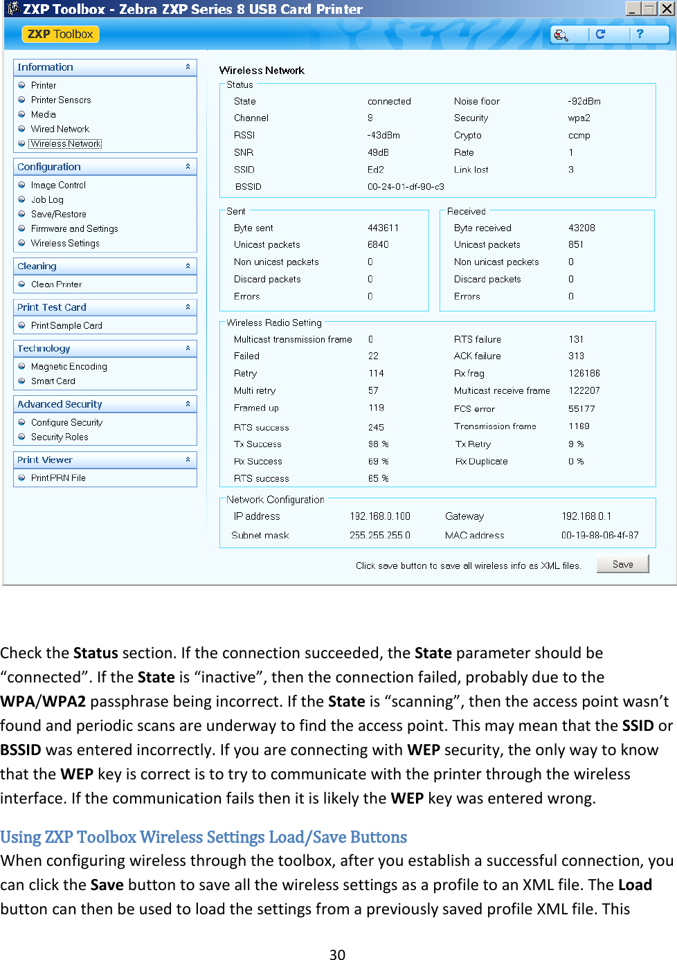
User Manual
Discussion / Help
Navigation