Zebra Technologies W2WLAN11G 802.11 b/g module User Manual
Zebra Technologies Corporation 802.11 b/g module
User manual
P1035089-001 Rev A
Zebra® ZXP Series 8™
Card Printer
Wireless
Reference Manual
Working Draft
March 31, 2011
Cover
2
© 2010 ZIH Corp. The copyrights in this manual and the software and/or firmware in the
printer described therein are owned by ZIH Corp. and Zebra’s licensors. Unauthorized
reproduction of this manual or the software and/or firmware in the printer may result in
imprisonment of up to one year and fines of up to $10,000 (17 U.S.C.506). Copyright violators
may be subject to civil liability.
Proprietary Statement This manual contains proprietary information of Zebra Technologies
Corporation and its subsidiaries. It is intended solely for the information and use of parties
operating and maintaining the equipment described herein. Such proprietary information may
not be used, reproduced, or disclosed to any other parties for any other purpose without the
express, written permission of Zebra Technologies.
Product Improvements Continuous improvement of products is a policy of Zebra Technologies.
All specifications and designs are subject to change without notice.
Liability Disclaimer Zebra Technologies takes steps to ensure that it’s published Engineering
specifications and manuals are correct; however, errors do occur. Zebra Technologies reserves
the right to correct any such errors and disclaims liability resulting there from.
Limitation of Liability In no event shall Zebra Technologies or anyone else involved in the
creation, production, or delivery of the accompanying product (including hardware and
software) be liable for any damages whatsoever (including, without limitation, consequential
damages including loss of business profits, business interruption, or loss of business
information) arising out of the use of, the results of use of, or inability to use such product,
even if Zebra Technologies has been advised of the possibility of such damages. Some
jurisdictions do not allow the exclusion or limitation of incidental or consequential damages, so
the above limitation or exclusion may not apply to you.
Important Use only the supplied antenna. Unauthorized
antennas, modifications or attachments could damage the
transmitter and may violate FCC regulations or local regulatory
requirements in your country.
3
Table of Contents
1 Introduction .......................................................................................................................................... 5
2 Networking Basics ................................................................................................................................. 6
Channels and communication modes ....................................................................................................... 6
Security ..................................................................................................................................................... 7
Authentication .......................................................................................................................................... 8
Network name (SSID) ................................................................................................................................ 8
Encryption ................................................................................................................................................. 8
Media access control address authentication .......................................................................................... 9
3 Installing Printer .................................................................................................................................. 10
4 Configuring the Printer ....................................................................................................................... 11
Network Settings ..................................................................................................................................... 12
Configuring the Printer through the Operator Control Panel ................................................................. 12
Configuring Wireless through the Printer Web Page ............................................................................. 22
Configuring Wireless through the Driver Toolbox .................................................................................. 25
Using ZXP Toolbox Wireless Settings Load/Save Buttons ....................................................................... 30
Using RADIO CONTROL Menu ................................................................................................................. 31
Using SET DEFAULTS Menu ..................................................................................................................... 32
Simple Roaming Used During Connection .............................................................................................. 32
Setting Up an Ad-Hoc (Peer) Network .................................................................................................... 33
Multi-homing Considerations ................................................................................................................. 37
5 Monitor Wireless Performance .......................................................................................................... 39
Wireless Info Pages ................................................................................................................................. 39
Signal Strength ........................................................................................................................................ 40
Noise Floor .............................................................................................................................................. 41
Data Rate................................................................................................................................................. 41
DHCP & MAC Address Info Page ............................................................................................................. 41
Wireless Statistics Info Page ................................................................................................................... 42
Wireless Statistics Success and Failure Rates ......................................................................................... 43
Main Status Display Wireless Errors ....................................................................................................... 43
Viewing Wireless Information through Printer Web Page ..................................................................... 45
Viewing Wireless Information through Windows Printer Driver Toolbox .............................................. 46
4
6 Troubleshooting .................................................................................................................................. 49
Wireless Troubleshooting Checklist ........................................................................................................ 49
Cannot Print Over Wireless Network ...................................................................................................... 50
Improve Wireless Signal Strength ........................................................................................................... 52
7 Technical Specifications ...................................................................................................................... 55
8 Glossary ............................................................................................................................................... 59
9 Compliance Information ..................................................................................................................... 64
5
1 Introduction
This manual is a supplementary document to the Zebra ZXP Series 8 Printer User Guide. This
manual provides the following information about installing and connecting the printer to a
wireless network:
1. The Networking basics chapter contains overview information about wireless
networking and the wireless features of the Zebra ZXP Series 8 printer.
2. The information for installing to a wireless network will be useful if you are installing the
printer to a wireless network, or if you wish to change printer or network settings after
you have installed the printer.
3. The Troubleshooting chapter contains troubleshooting information.
In addition, this manual contains a chapter of regulatory information and a glossary of wireless
terms.
6
2 Networking Basics
The Zebra ZXP Series 8 printer has an internal print server that supports both wired and
wireless Ethernet connectivity. The wired Ethernet capability is standard with the printer while
the wireless capability is an option that can be ordered through the factory. The wireless option
is field upgradeable, but requires partial disassembly of the printer covers to remove the wired
daughter card and replace it with a wired/wireless daughter card (see separate document that
describes daughter card installation in the printer). The printer supports simultaneous wired
and wireless connections, a capability referred to as multi-homing, in this case having two
separate interfaces with separate IP addresses. To connect to a wireless network, the printer
uses wireless protocol IEEE 802.11b/g that communicates data through radio transmission.
After installing the printer to a wireless network, cables are not required to communicate with
the computers or devices that are part of the network.
A wireless local area network (WLAN) is a collection of two or more computers, printers, and
other devices linked by radio waves. A WLAN uses high-frequency airwaves (radio) to
communicate information from one point to another.
To connect a computer or device to a wireless network, the computer or device must have a
wireless network adapter. The Zebra ZXP Series 8 printer uses an internal networking
component that contains a wireless radio. No cabling is necessary between networked devices
that use wireless technology, although it is possible to use a USB or wired Ethernet cable to
configure your printer for a wireless network.
Common wireless network adapters include the following:
• USB adapter: An external device that connects to a USB port on the computer.
• Notebook adapter: A PCMCIA card that plugs directly into one of the PCMCIA slots on
your laptop or other portable computer.
• Desktop computer adapter: A dedicated ISA or PCI card, or a PCMCIA card with a special
adapter that plugs into your desktop computer.
Channels and communication modes
The band of radio signals used for IEEE 802.11b/g wireless networking is segmented into
specific frequencies, or channels. For IEEE 802.11b/g wireless networks, 14 channels are
available. Each country/region specifies the channels that are authorized for use. For example,
in North America, only channels 1 through 11 are allowed. In Japan, channels 1 through 14 can
7
be used (channel 14 – 802.11b only). In Europe, channels 1 through 13 are allowed. Because
existing standards change frequently, you should check with your local regulatory agencies for
authorized channel use. In most countries/regions channels 10 and 11 may be used without
restriction.
Channel selection depends on the communication mode of the network. The communication
mode defines how devices, such as computers and printers, communicate on a wireless
network. There are two primary types of wireless communication modes: infrastructure and ad-
hoc.
In infrastructure mode, the printer communicates with network computers through a wireless
access point (AP) or a base station. The access point acts as a central hub or gateway
connecting wireless and, optionally, wired devices (most access points have an integrated
Ethernet controller to connect to an existing wired-Ethernet network).
In ad-hoc mode, which is sometimes called peer-to-peer mode, the printer communicates with
your computer directly, rather than through an access point or base station. Each device on an
ad-hoc network must have a wireless network adapter. The adapter enables each device to
communicate with the other devices on the network. Ad-hoc mode is usually limited to simple,
small wireless networks because performance degrades significantly after connecting too many
network devices. This option is most often used if you are connecting only two network devices
that are not sharing an Internet connection. Only WEP security is available in ad-hoc mode.
Security
As with other networks, security for wireless networks focuses on access control and privacy.
Traditional wireless network security includes the use of Service Set Identifiers (SSIDs), open or
shared-key authentication and static Wired Equivalent Privacy (WEP) keys or Wi-Fi protected
access (WPA or WPA2).
It is highly recommended that you implement a wireless security scheme (preferably WPA2)
prior to setup. While the printer can connect to an open AP, running an open wireless AP will
allow anyone within range of the AP full access to all devices connected to the AP with
potentially damaging results. While WEP security is still in use today, WEP security has been
broken for many years. There are tools available on the internet that will allow anyone with
even basic networking knowledge to break the WEP security and derive the WEP key within 3
minutes, giving them full access to devices on your network. The best security is obtained by
using WPA2 security with AES encryption.
Authentication and encryption are two different approaches to network security.
Authentication verifies the identity of a user or device before granting access to the network,
making it more difficult for unauthorized users to access network resources. Encryption
8
encodes the data being sent across the network, making the data unintelligible to unauthorized
users. Both of these security methods are common on wireless networks.
Authentication
The Zebra ZXP Series 8 printer supports Open System authentication. A network with Open
System authentication does not screen network users based on their identities and usually
involves supplying the correct SSID. Such a network might use Wired Equivalent Privacy (WEP)
encryption to provide a first level of security, or Wi-Fi protected access (WPA/WPA2) to provide
security by encrypting data sent over radio waves from one wireless device to another wireless
device. The printer allows for WEP, WPA or WPA2.
Network name (SSID)
Wireless devices are configured with the name of the network to which they will connect. The
network name is also called the SSID and identifies the ESS (Extended Service Set) that is
normally associated with larger infrastructure networks. The SSID should not be considered a
security feature because it can be easily identified. However, as a network administration or
management feature, it does provide basic network access control.
It is common practice to setup access points such that the SSID is not broadcast (hidden or
invisible). The printer can connect to invisible access points, although the user must know the
SSID name and correctly enter it into the printer. There is a belief that that hiding the SSID adds
extra security to the network. This is in fact false as a device connecting to a network must send
the SSID in the clear and the SSID can be easily obtained from the association management
frame. Hiding the SSID simply makes it more error prone to connect to a network.
Encryption
To reduce your network exposure to eavesdropping, establish a wireless security key for your
network. The printer supports the WEP RC4 encryption, WPA TKIP encryption and WPA2 CCMP
encryption (a form of AES encryption), which hinders unauthorized users from accessing data
transmitted over the radio waves. For WEP, a single static WEP key (40 or 104 bits) is installed
in the printer. Each computer or device is configured with the same key to communicate on
that network. The most secure encryption is achieved using WPA2 with CCMP.
WPA and WPA2 security provides the means to deploy dynamic encryption keys to devices on
the network. There are two approaches that are used for key deployment which are usually
referred to as Personal and Enterprise. In the Personal mode, a Pre-Shared Key (PSK) is
deployed on each network access point and device. The PSK is then used to derive Transient
Keys which are used between an access point and the devices which are connected to it. In the
Enterprise mode, an authentication server is used to deploy keys using one of several available
9
Extensible Authentication Protocols (EAP). Currently, the ZXP Series 8 printer only supports
Personal mode.
For WPA or WPA2 Personal, a single, 8 – 63 character passphrase is entered into the access
point. The same passphrase must be entered into the printer. The access point and printer each
derive the same 32 byte PSK from the passphrase using the password-based key derivation
function 2 (PBKDF2) from RFC 2898. The importance of picking a secure passphrase cannot be
overstressed. The most prevalent security attack against WPA-PSK is a brute force dictionary attack,
using a list of common words to “guess” your passphrase. So a passphrase like “darthvader” could result
in your security being quickly compromised. When constructing your passphrase, keep the following
suggestions in mind:
• Use more than 8 characters. The more characters, the more secure.
• Use a combination of uppercase, lower case, numeric and punctuation characters.
• Use random characters, avoid using recognizable words.
Media access control address authentication
Some WLAN vendors support authentication based on the physical address, or MAC address, of
the client Network Interface Card (NIC). In this scenario, an access point allows association by a
client only if that client’s MAC address matches an address in an authentication table used by
the access point. This is not configurable through the printer.
10
3 Installing Printer
The printer with the wireless option ships with the wireless radio pre-installed in the printer. An
antenna is shipped in the box with the printer. The antenna must be connected to the rear of
the printer before using the wireless interface. Lightly push the antenna onto the printer
antenna connector and rotate the knurled antenna connector until finger tight.
The antenna orientation is important to maximize the wireless signal strength. Inspect the
access point antenna(s) and try to put the printer antenna in a similar orientation. After
connecting the printer to the wireless network, the antenna orientation can be adjusted to
maximize signal strength.
802.11b/g has an indoor open range of 100 ft at maximum data rate and 300 ft at minimum
data rate. As the distance between the printer and the access point increases, the signal
strength decreases. If there are intervening walls, unpredictable signal strength attenuation will
occur. Decreasing signal strength results in automatic data rate reduction. At the longest
distance, network traffic can become very slow.
Printer location is important to ensure that adequate signal strength is achieved. Follow these
suggestions:
• Position the printer as close to the access point that it will connect to as possible.
• If possible, orient the printer such that there is a clear line of sight between the printer
antenna and the access point antenna.
• Locate the printer such that there are no intervening walls in the line of sight between
antennas.
• Do not put the printer in a cabinet, especially not a metal one.
• Do not locate large metal objects close to the printer antenna.
• Do not locate the printer close to devices that emit RF radiation in the 2.4 GHz range.
Such devices might include: microwave ovens, cordless phones, wireless surveillance
cameras, baby monitors, wireless video transmitter and Bluetooth devices.
Once you have your printer connected to a wireless network, the printer can provide
information on the quality of the connection to the network. If the quality is poor, there are
several approaches that can be taken to improve the quality.
Warning! Only use the antenna that is shipped with the printer to ensure regulatory
compliance for the transmit power.
11
4 Configuring the Printer
To set up the printer for wireless printing, you need to know:
• The name of your wireless network. This is also known as the Service Set Identifier
(SSID).
• If encryption was used to secure your network.
• The security key (either a WEP key or WPA passphrase) that allows other devices to
communicate on the network if encryption was used to secure your network.
• If the access point you will connect to doesn’t broadcast the SSID, you will need to know
the BSSID (MAC Address of the wireless interface) for the AP. Make sure that you have
the correct MAC address, your AP may have several.
If your wireless access point (wireless router) is using Wired Equivalent Privacy (WEP) security,
the WEP key should be exactly 10 or 26 hexadecimal characters. Hexadecimal characters are A–
F, a–f, and 0–9.
If your wireless access point (wireless router) is using Wi-Fi Protected Access (WPA or WPA2)
security, the WPA passphrase should be from 8 to 63 ASCII characters. ASCII characters in a
WPA passphrase are case-sensitive.
If your wireless network is not using security, then you will not need a security key. Using a
wireless network with no security is not recommended because it can allow intruders to use
your network resources without your consent.
Note: Make sure you copy down the security key and SSID exactly, including any capital letters,
and store it in a safe place for future reference. If you do not know the SSID of the network that
your computer is connected to, launch the wireless utility of the computer network adapter
and look for the network name. If you cannot find the SSID or the security information for your
network, see the documentation that came with the wireless access point (wireless router), or
contact your system support person.
There are three ways to configure the printer to connect to a wireless network:
1. Configure the printer through the Operator Control Panel.
2. Configure the printer through the Windows Printer Driver Toolbox using USB.
3. Configure the printer through the printers Web Page using wired Ethernet.

12
Network Settings
Every device connected to an Ethernet network must be assigned an IP Address, Subnet Mask
and Default Gateway Address. An IPv4 Address consists of a 32-bit binary number, which is
typically presented as four decimal numbers (one for each 8-bit byte) separated by decimal
points (for example: 192.168.0.100). The subnet mask determines what subnet an IP address
belongs to. A typical subnet would be 255.255.255.0. As applied to the previous example,
devices with IP Addresses in the range of 192.168.0.1 through 192.168.0.255 would all be in the
same subnet. The default gateway is the node connecting the internal networks and the outside
network (Internet).
In order to configure the printer, these settings must be known or DHCP must be used to automatically
configure the printer. If the network has a DHCP server, the printer can request the network settings
from the DHCP server after establishing a connection to the access point. Otherwise, these settings must
be known and manually entered into the printer. Check with your network administrator if you are not
sure about whether to use DHCP or manual settings.
When using DHCP, be aware that the DHCP server may periodically change the IP Address assigned to
the printer. If this happens, the Windows Printer Driver may no longer be able to communicate with the
printer. To prevent this, DHCP servers can be configured to lock an IP Address to a specific MAC address.
Obtain the wireless MAC address from the Operator Control Panel (make sure you get the correct MAC
Address, there are two, one for wired and one for wireless) and use this to configure the DHCP server.
Some DHCP servers are configured to reject DHCP requests from unknown devices. Again, the MAC
address can be used to configure the DHCP server to recognize the printer.
If you plan to use both wired and wireless Ethernet interfaces at the same time, see the “Multi-
homing Considerations” section. The configuration of the IP Address and Subnet Mask on each
interface must be set correctly depending upon whether the two interfaces are connected to
the same network or totally separate networks. Improperly configured network settings may
result in a communications failure.
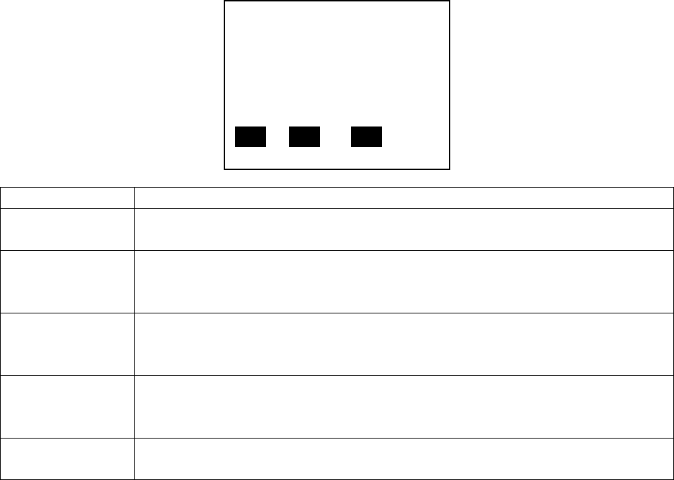
Configuring the Printer through the Operator Control Panel
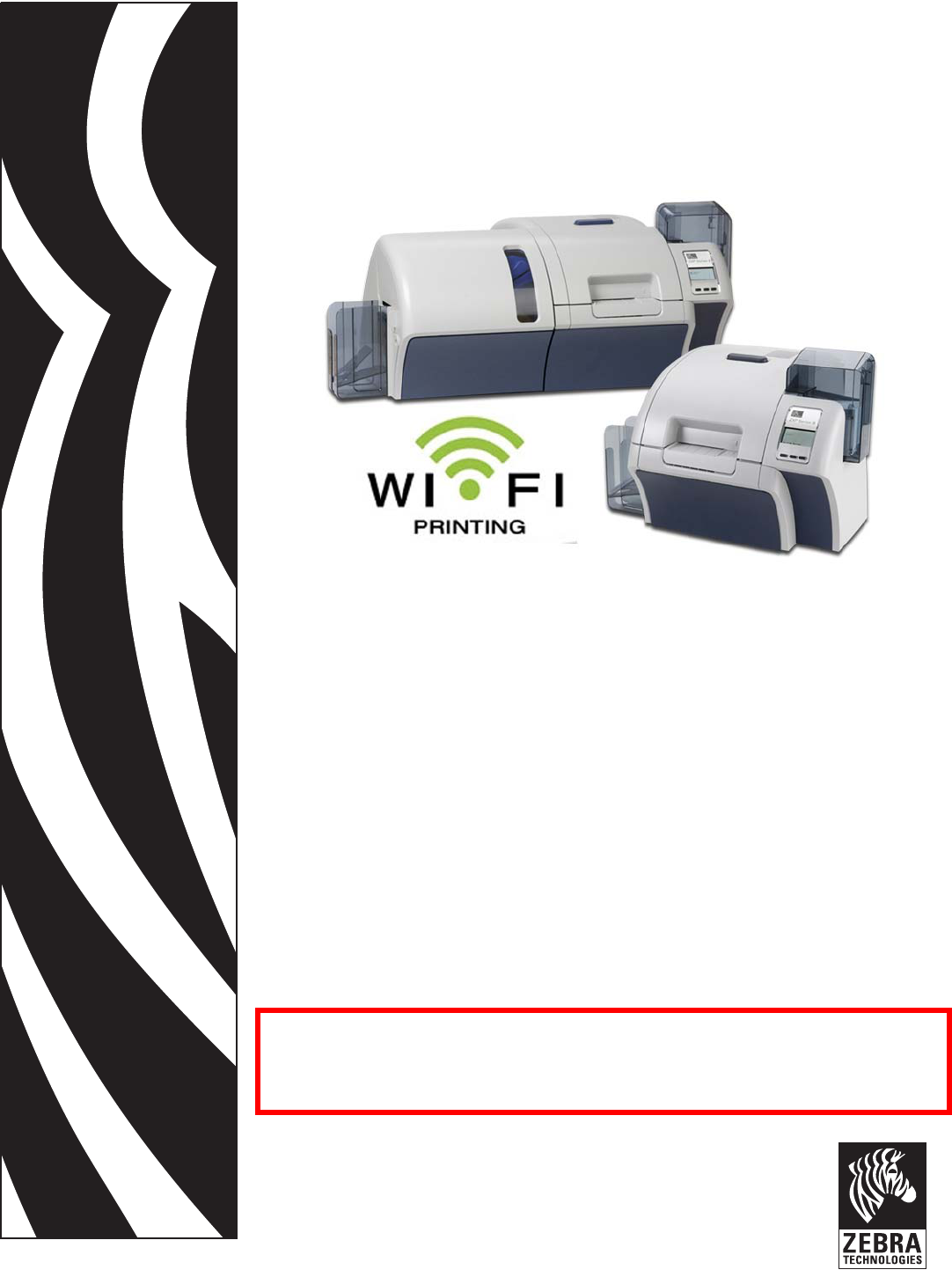
When powered up, the OCP will display the following:
Press the MENU soft-key and the display changes to:
READY
MENU INFO
13
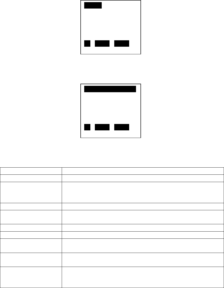
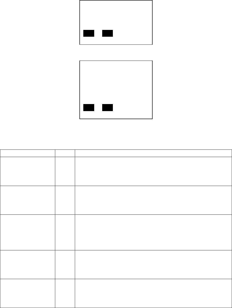
Press the DOWN soft-key until “WIRELESS SETTINGS” is highlighted in reverse video then press
SELECT and the display changes to:
There are several selections hidden. These can be seen by pressing the DOWN soft-key. The
selections are as follows:
Menu Selection Description
RETURN WITHOUT SAVE Exit the current menu, returning to the previous menu.
SAVE SETTINGS Save any setting that have been changed then return to the
previous menu. The printer will then remember these settings after
a power cycle.
RADIO CONTROL
Turn the radio on or off.
SETUP WIZARD Enter the setup wizard, which takes you through the steps to
connect to an access point one step at a time.
DHCP MODE
Enable disable DHCP mode.
SET IP ADDRESS Set the IP Address. Only needed if DHCP is disabled.
SET SUBNET MASK
Set the Subnet Mask. Only needed if DHCP is disabled.
SET DEFAULT GATEWAY
Set the Default Gateway. Only needed if DHCP is disabled.
SET DEFAULTS
Erase all the wireless settings. If the radio is on, the radio is turned
off. If you want the defaults to be permanent, you will need to also
select “SAVE SETTINGS”.
RETURN
> PRINT TEST CARDS
> NETWORK SETTINGS
> LAMINATOR SETTINGS
> ADVANCED SETTINGS
> WIRELESS SETTINGS
UP DOWN SELECT
RETURN WITHOUT SAVE
SAVE SETTINGS
> RADIO CONTROL
> SETUP WIZARD
> DHCP MODE
> SET IP ADDRESS
UP DOWN SELECT

14
Step 1:
Determine whether you plan to enable DHCP to automatically obtain the IP Address, Subnet
Mask and Gateway Address. Enter the DHCP Mode menu by pressing the DOWN soft-key until
“DHCP MODE” is highlighted then press SELECT and the display changes to:
Use the UP and DOWN soft-keys to highlight “DHCP ENABLE” or “DHCP DISABLE” then press the
SELECT soft-key.
Note: if you enabled DHCP, you don’t need to enter an IP Address, Subnet Mask and Default
Gateway. Skip to Step 5.
Warning: if you disable DHCP, it is very important that you enter the correct IP Address, Subnet
Mask and Default Gateway for the network. If any of them are entered wrong, the
communications may fail. The IP Address that you use must not be assigned to any other device
on your network. If you are not sure what settings to use, check with your IT department. You
can also inspect the settings for a computer on your network. On Windows XP, click Start then
Run. In the Open box type “cmd” then click Ok to open a Command Prompt window and type
“ipconfig /all” at the prompt. You can then see the IP Address, Subnet Mask and Default
Gateway the computer is configured to use. It is likely that you can use the same Subnet Mask
and Gateway settings in your printer. You will need to use a different and unused IP Address. To
verify that the one you plan to use is available, type “ping xx.xx.xx.xx” at the command prompt
where xx.xx.xx.xx is the IP Address you plan to use. If the ping times out, that means that no
device on the network with that IP Address responded. This is not a guarantee that the IP
Address is available as a device with that IP Address could be powered down or temporarily
disconnected from the network.
Step 2:
Enter the Set IP Address menu by pressing the DOWN soft-key until “SET IP ADDRESS” is
highlighted then press SELECT and the display changes to:
RETURN
DHCP ENABLE
DHCP DISABLE
UP DOWN SELECT

15
Use the CHANGE soft-key to change the selected digit. Each press of CHANGE increases the
digit value by 1 with a roll-over to zero when necessary. The selected digit will flash. Use the
NEXT soft-key to select the next digit in the sequence. Pressing NEXT when the last digit is
selected will result in the first digit being selected. Press EXIT to save the current IP Address and
exit the menu. Before pressing EXIT, all of the digits on the display must match the desired IP
Address.
Step 3:
Enter the Set Subnet Mask menu by pressing the DOWN soft-key until “SET SUBNET MASK” is
highlighted then press SELECT and the display changes to:
Use the CHANGE soft-key to change the selected digit. Each press of CHANGE increases the
digit value by 1 with a roll-over to zero when necessary. The selected digit will flash. Use the
NEXT soft-key to select the next digit in the sequence. Pressing NEXT when the last digit is
selected will result in the first digit being selected. Press EXIT to save the current Subnet Mask
and exit the menu. Before pressing EXIT, all of the digits on the display must match the desired
Subnet Mask.
Step 4:
Enter the Set Default Gateway menu by pressing the DOWN soft-key until “SET DEFAULT
GATEWAY” is highlighted then press SELECT and the display changes to:
IP: 000.000.000.000
CHANGE NEXT EXIT
Mask: 000.000.000.000
CHANGE NEXT EXIT

16
Use the CHANGE soft-key to change the selected digit. Each press of CHANGE increases the
digit value by 1 with a roll-over to zero when necessary. The selected digit will flash. Use the
NEXT soft-key to select the next digit in the sequence. Pressing NEXT when the last digit is
selected will result in the first digit being selected. Press EXIT to save the current Default
Gateway Address and exit the menu. Before pressing EXIT, all of the digits on the display must
match the desired Default Gateway Address.
Step 5:
Save the current configuration to permanent storage. This will insure that the DHCP Mode, IP
Address, Subnet Mask and Default Gateway are remembered by the printer after a power cycle.
Use the UP and DOWN soft-keys to highlight “SAVE SETTINGS” then press the SELECT soft-key.
This will return you to the main printer menu. Reenter the Wireless Settings menu for the next
step.
Step 6:
Enter the Setup Wizard menu by pressing the DOWN soft-key until “SETUP WIZARD” is
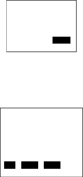
highlighted then press SELECT and the display changes to:
Press the SCAN soft-key to begin scanning for access points that are within range of your
printer or press EXIT to exit this menu and return to the Wireless Settings menu. After pressing
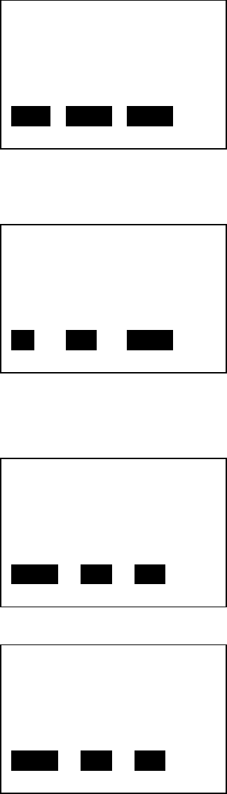
the SCAN soft-key, the display changes to:
GW: 000.000.000.000
CHANGE NEXT EXIT
BEGIN CONNECTING YOUR
PRINTER TO A WIRELESS
ACCESS POINT. PRESS
SCAN TO START.
SCAN EXIT
17
The printer will conduct active scans on all the channels allowed for your regulatory domain.
The scanning process is repeated multiple times over all the channels to insure that all AP’s are
identified. This can take over a minute to complete. Once the scanning process completes the
display changes to:
The OCP will display the information for a single access point. The top line displays the SSID and
the 2nd line the BSSID or MAC Address for the access point. If the SSID name is too long to fit on
the top line of the display, it will wrap to the 2nd line and the BSSID will not be displayed. If the
SSID of the access point is not broadcast (hidden or invisible), the SSID will display as:
SSID: <HIDDEN>
The 3rd line indicates the channel the access point operates on (can be 1 – 14) and the signal
strength in percent (more information on signal strength provided later in this document). The
4th line indicates the security mode the access point is configured to use. This could be: NONE,
WEP, WPA, WPA2 or WPA & WPA2 (both available simultaneously). The 5th line indicated the
type of encryption being used by the access point. This could be: NONE, RC4 (used for WEP),
TKIP, CCMP (a variant of AES) or TKIP & CCMP (both available simultaneously). The 5th line
indicates the maximum data rate supported by the access point. This will usually be 11 Mbps if
the access point is only capable of 802.11b and 54 Mbps if the access point is capable of
802.11g.
Pressing the NEXT soft-key advances the display to the next access point found during the scan.
When the last access point found is displayed, pressing NEXT will cause the first access point to
SSID: Test
MAC:00:a0:f8:be:fe:72
Chan = 1 SIG = 52%
SEC MODE: WPA
CRYPTO: TKIP
MAX SPEED: 54 Mbps
NEXT SELECT CANCEL
WAIT WHILE SCAN
COMPLETES. USE NEXT
TO SCROLL THROUGH
AP'S AND SELECT ONE.
CANCEL

18
display again. The CANCEL soft-key can be pressed at any time to abort the Setup Wizard and
return to the main Wireless menu. By knowing the SSID and/or BSSID, the access point you wish
to connect to can be found in the scan list. There may be occasions where the access point of
interest is not displayed. This can happen due to noise or interference during the scanning. If
you can’t find the access point, press the CANCEL soft-key and retry the Setup Wizard until the
access point is found. Once the access point you wish to use is displayed on the OCP, press the
SELECT soft-key. If the signal strength for the selected access point is less than 25%, the display
changes to:
When the signal strength is less than 25%, it is likely that you will have problems connecting to
the access point or have problems after the connection is established. This is only a warning to
offer you the opportunity to resolve potential problems by improving the signal strength before
continuing. Press the CANCEL button to exit the Setup Wizard or NEXT to continue connecting
to this access point.
If the SSID is hidden, it is necessary to enter SSID manually, otherwise this step is bypassed. The
display for manually entering the SSID looks like:
The SSID must be entered one character at a time. Each character can be any visible ASCII
character. The character that is currently being set will slowly blink. Use the CHANGE soft key to
cycle through the ASCII character set until the desired character is shown (Remember that the
SSID is case sensitive). If there are more characters that need to be set, then press the NEXT
soft-key to add another character and use the CHANGE soft-key to select the correct ASCII
character. When the last character has been set (and while it is still blinking) press the EXIT
soft-key to complete the SSID entry. (Warning - Do not press the NEXT soft-key after the last
character has been set otherwise you will need to repeat this entire step.) Note that entering
the SSID text incorrectly will prevent successful connection to the access point.
THE SIGNAL STRENGTH
IS < 25%. TRY
CHANGING ANTENNA
ORIENTATION OR MOVE
PRINTER CLOSER.
NEXT CANCEL
ENTER SSID, 1 - 32
CHARACTERS:
0
CHANGE NEXT EXIT
19
If the access point security is set to WEP, the display changes to:
-OR-
If the access point security supports both WPA and WPA2, the display changes to:
When selecting the WEP key size, you must know the key size that the access point is
configured with. Once you press either the WEP40 or WEP104 soft-key, you will need to enter
the WEP key and the display changes to:
-OR-
Use the CHANGE soft-key to scroll through the hex character choices (0 -9, A – F). Use the NEXT
soft-key to select the next character position to change. The blinking character indicates the
SELECT WEP KEY SIZE.
WEP40 WEP104 CANCEL
SELECT SECURITY MODE.
IF YOU ARE UNSURE,
PICK WPA2.
WPA WPA2 CANCEL
ENTER WEP KEY, 10 HEX
CHARACTERS:
0000000000
CHANGE NEXT EXIT
ENTER WEP KEY, 26 HEX
CHARACTERS:
000000000000000000000
00000
CHANGE NEXT EXIT
20
character position that is selected. When the display exactly matches the WEP key of the access
point, press the EXIT soft-key.
For WPA and WPA2, you may need to select the encryption mode if more than one is available.
If this is the case, the display changes to:
Press either the CCMP or TKIP soft-key to select the encryption mode. Remember that CCMP is
the stronger encryption. For WPA and WPA2, after the security mode and encryption modes
have been selected or automatically determined (if only one mode is available, the selection
display is bypassed), the WPA Passphrase must be entered. The display changes to:
The passphrase must be entered one character at a time. Each character can be any visible
ASCII character. The character that is currently being set will slowly blink. Use the CHANGE soft
key to cycle through the ASCII character set until the desired character is shown (Remember
that the passphrase is case sensitive). If there are more characters that need to be set, then
press the NEXT soft-key to add another character and use the CHANGE soft-key to select the
correct ASCII character. When the last character has been set (and while it is still blinking) press
the EXIT soft-key to complete the passphrase entry. The EXIT key will not work until at least 8
characters have been entered. (Warning - Do not press the NEXT soft-key after the last
character has been set otherwise you will need to repeat this entire step.) Note that entering
the passphrase text incorrectly will prevent successful connection to the access point.
At this point, all the information has been collected that is necessary to connect to the access
point. Please be aware that not all of the Setup Wizard screens shown above will be seen. The
printer will bypass screens that that are unnecessary to display. For instance, if an access point
is setup with only WPA security, only TKIP security and the SSID is broadcast, only the “Enter
WPA Passphrase” setup screen will be seen. The display should now be:
SELECT ENCRYPTION
MODE. IF YOU ARE
UNSURE, PICK CCMP.
CCMP TKIP CANCEL
ENTER WPA PASSPHRASE
8 – 63 CHARACTERS:
0
CHANGE NEXT EXIT

21
The CANCEL soft-key can be used to exit the Setup Wizard without connecting. Press the
CONNECT soft-key to connect to the access point. The printer will conduct a wireless
association and proceed with security key handshaking with the access point if necessary. The
display changes to:
If the connection completes successfully, the current wireless settings are automatically saved
so that the printer will automatically re-connect after a power cycle. The display changes back
to the main wireless menu. The “RETURN WITHOUT SAVE” selection can be used to exit from
the wireless menu. The antenna icon on the OCP will be active, providing an indication of the
signal strength with up to 4 bars. If connection to the access point fails, the display will change
to:
If this occurs, there is likely a problem with the data entered or the signal strength is too low to
reliably connect to the access point. Try improving the signal strength if below 50%. Make sure
that the SSID and security key/passphrase is correct then retry the Setup Wizard. If connection
still fails, refer to the troubleshooting section for additional help.
THE PRINTER IS READY
TO CONNECT TO THE AP.
PRESS CONNECT TO
PROCEED.
CONNECT CANCEL
WAIT FOR THE AP
CONNECTION TO
COMPLETE.
CANCEL
AP CONNECTION FAILED.
CHECK KEY, SSID AND
SIGNAL STRENGTH.
CANCEL
22
Configuring Wireless through the Printer Web Page
This requires that the printer be connected to a computer through wired Ethernet. Set the
DHCP mode, IP Address Subnet Mask and Default Gateway as needed for the wired interface. If
DHCP is enabled, use the OCP INFO soft-key to determine the IP Address for the wired
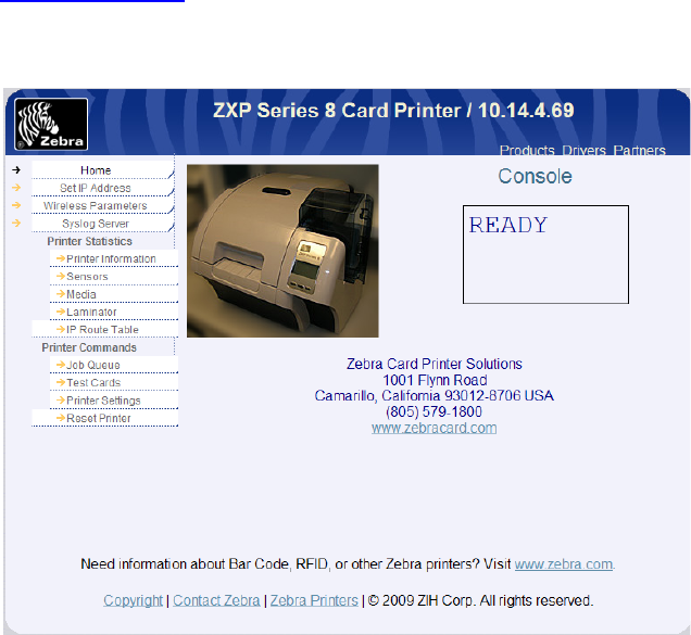
Ethernet. Open a browser window on a computer connected to the same network as the
printer and enter the printer IP address, like:
http://10.14.4.69
The printer web page should then display:
Click on the “Wireless Parameters” entry from the list of the left of the web page and enter
User name (default is: admin) and Password (default is: 1234). The web page now changes to
one specific to wireless setup:

23
Step 1:
Make any changes needed to DHCP Enable, IP Address, Subnet Mask and Gateway then press
Submit.
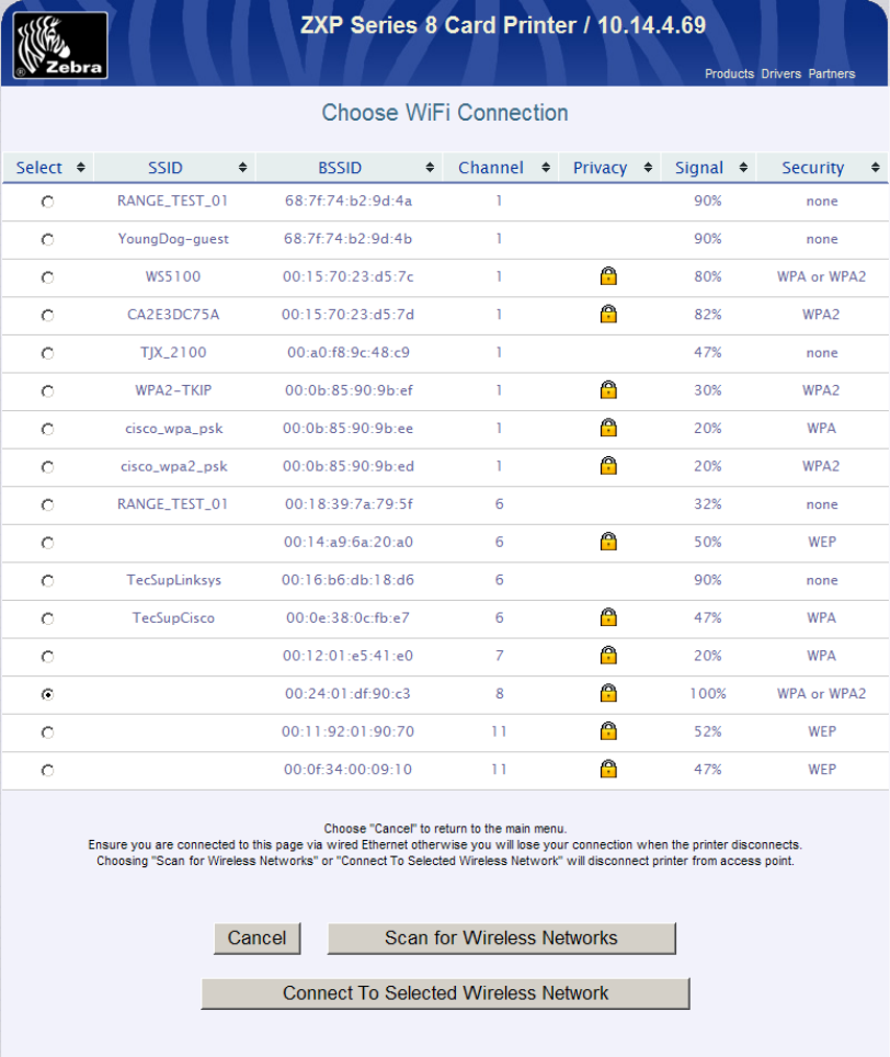
Step 2:
Click the “Available Networks” entry from the list of the left of the web page. Click the Scan for
Wireless Networks button. Wait for the scan to complete. The web page should look like:
24
If the access point you want to connect to isn’t shown, Click Scan for Wireless Networks again
until it is shown. Pick the desired access point using the radio button on the left of the list. Click
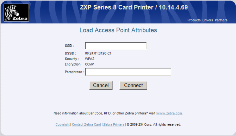
Connect To Selected Wireless Network to proceed. The web page changes to:
25
Step 3:
Enter any information required, like: SSID, Security, Encryption and Passphrase. Click Connect.
Wait for connection to complete or for an error message.
If connection was successful, the wireless parameters were automatically saved so that the
printer will automatically connect the next time the printer is powered on. The wired Ethernet
connection can now be disconnected if desired.
Configuring Wireless through the Driver Toolbox
This requires that the printer be connected to a computer through USB or wired Ethernet with
the Windows printer driver installed and functional. Refer to the ZXP Series 8 User Guide for
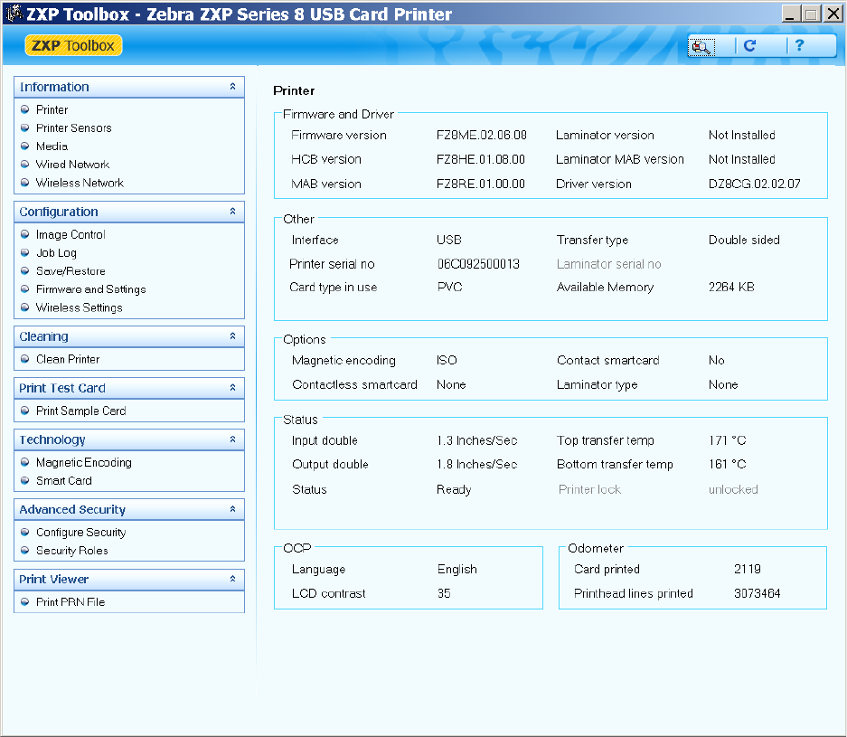
instructions on driver installation. Once the Windows printer driver is installed and functioning,
open the ZXP Toolbox. The following screen will be displayed:
26
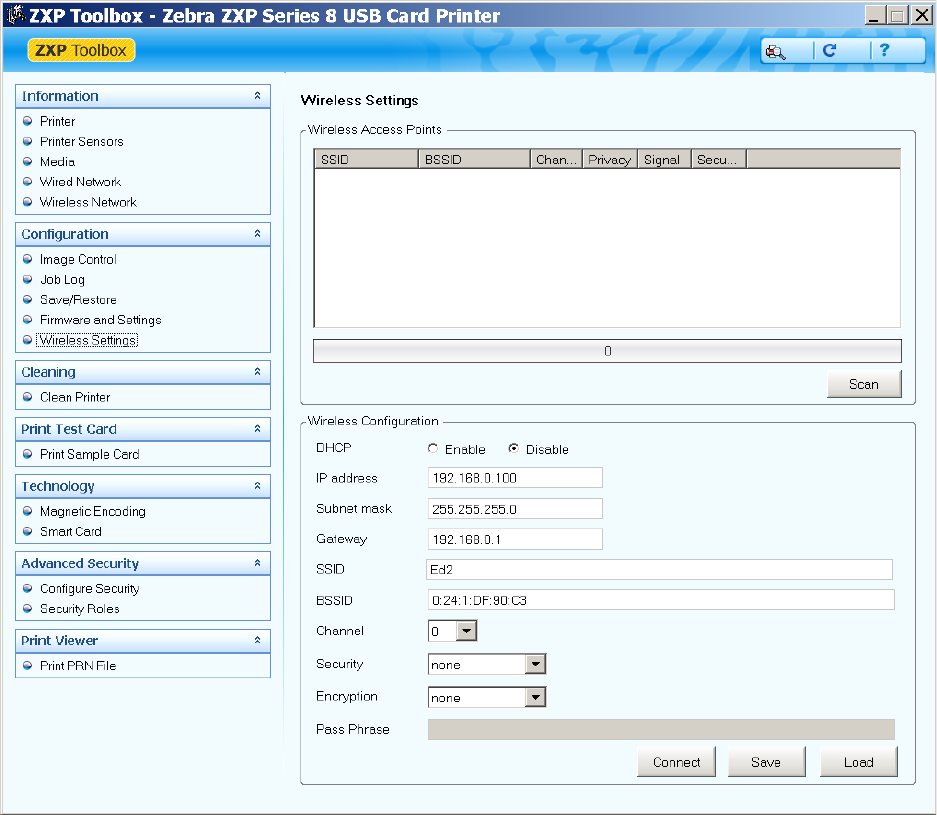
Under the Configuration section, click on Wireless Settings. The following screen will be
displayed:
27
There are two approaches that can be used to configure the printer’s wireless settings. If all the
necessary information is known (SSID, BSSID, Channel, Security, Encryption and Passphrase)
these parameters can be directly entered into the Wireless Configuration. The alternate
approach is to request that the printer scan for wireless access points and select one. This
automatically fills in most of the Wireless Configuration parameters.
Step 1:
Make any changes needed to DHCP Enable, IP Address, Subnet Mask and Gateway.
If directly entering the wireless settings, skip to Step 4.
28
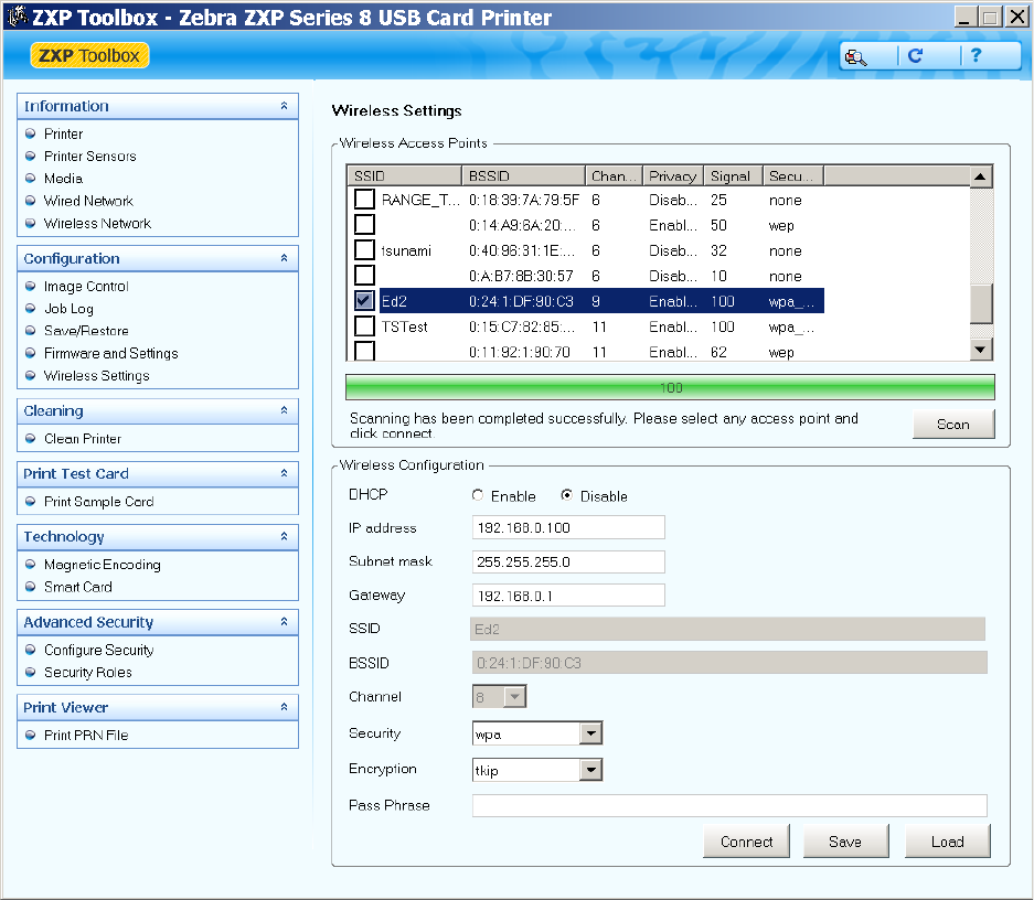
Step 2:
Press the Scan button to initiate a scan. Once the scan is complete, scroll through the wireless
access points and select the one you want to connect to using the associated checkbox. The
display should look like:
Step 3:
If the SSID is not displayed (access point configured to not broadcast SSID), enter the SSID.
Select the desired Security and Encryption. The choices will be limited to what the access point
can accept. If the access point is configured for WEP, you must choose correctly between
WEP40 and WEP104 (there is no way do determine the WEP key size). Skip to Step 5.
29
Step 4:
Enter the SSID, BSSID (format xx:xx:xx:xx:xx:xx), Channel, Security and Encryption. The Channel
setting is a hint to the printer about which channel the access point will located on. Providing
the correct channel will result in a faster connection to the access point when powering up the
printer. If you enter the wrong channel it will not cause the connection to fail. The printer will
first scan for the access point on the indicated channel and if not found will widen the search to
all channels. Some wireless access points can be configured to auto select their channel when
powered on (channel used may be different each time). In this case set the channel to zero,
which tells the printer to scan all channels to find the access point before connecting. If you
don’t know the correct channel, setting the channel to zero is the best choice. Set the Security
entry before Encryption. The Encryption choices will be limited by the Security setting.
Warning! When using manual entry of wireless settings, you must be careful to enter all the
data correctly or the printer may fail to connect to an access point. If you are not sure about the
settings, check with your IT department. Most access points provide a web page for
configuration. If you can access this web page you can determine the proper settings for SSID,
BSSID, Channel, Security and Encryption. Be careful with the Security and Encryption settings.
An access point may be configured to allow only certain Security/Encryption capabilities, like
only WPA2/CCMP. In this case, trying to connect with WPA/TKIP would fail.
Step 5:
Enter the Key (if using WEP40 or WEP104) or the Passphrase (if using WPA or WPA2). If the
security is WEP, you must enter exactly 10 (WEP40) or 26 (WEP104) hex characters (0 – 9, A –
F). If the security is WPA or WPA2, you must enter at least 8 visible ASCII character for the
passphrase. The key or passphrase must be identical to the one that has been entered into the
wireless access point. Check with your IT department to get the correct key or passphrase.
Warning! Entering an incorrect WEP key will not result in a failure to connect, but
communications with the printer will not work through the wireless interface. Entering an
incorrect WPA/WPA2 passphrase will result in a connection failure. It is very important to use
the correct key or passphrase and enter it correctly.
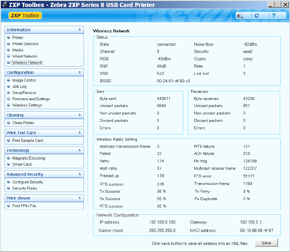
Step 6:
Press the Connect button. A dialog box displays to indicate that the connection process has
been initiated. Press Ok to remove the dialog. Under the Information section on the left side of
the Toolbox click Wireless Network. The following dialog appears:
30
Check the Status section. If the connection succeeded, the State parameter should be
“connected”. If the State is “inactive”, then the connection failed, probably due to the
WPA/WPA2 passphrase being incorrect. If the State is “scanning”, then the access point wasn’t
found and periodic scans are underway to find the access point. This may mean that the SSID or
BSSID was entered incorrectly. If you are connecting with WEP security, the only way to know
that the WEP key is correct is to try to communicate with the printer through the wireless
interface. If the communication fails then it is likely the WEP key was entered wrong.
Using ZXP Toolbox Wireless Settings Load/Save Buttons
When configuring wireless through the toolbox, after you establish a successful connection, you
can click the Save button to save all the wireless settings as a profile to an XML file. The Load
button can then be used to load the settings from a previously saved profile XML file. This

31
provides a means to quickly restore connection to a particular access point or select connection
to one of several access points available using different profiles. It might also be useful to setup
a group of printers to all connect to the same access point.
Warning! When using the Save button, the WEP key or WPA passphrase can be saved in the
XML file. If you are concerned about the security risk of exposing the key or passphrase in a
plain text file, then delete the key or passphrase entry before clicking Save. In this case, the key
or passphrase will not be saved to the file. When the Load button is used, the key or passphrase
will need to be manually entered.
Using RADIO CONTROL Menu
The Radio Control menu allows you to turn the radio on and off. After selecting the menu, the
display changes to:
Use the UP and DOWN soft-key to select enable or disable then press SELECT. If the radio is
connected and you select disable, the radio is disconnected from the access point. If the radio is
not connected and you select enable and the stored wireless parameters are valid, a
connection to the access point is attempted. The display changes to:
If the connection succeeds, the display changed back to the main wireless menu. Before
attempting a connection, the wireless parameters are checked to see if they are valid (this
doesn’t guarantee that a connection will occur as the parameters may be valid but not correct
for the access point). If the parameters are found to be invalid, the display changes to:
RETURN
RADIO ENABLE
RADIO DISABLE
UP DOWN SELECT
WAIT FOR THE AP
CONNECTION TO
COMPLETE.
CANCEL

32
In this case, the Setup Wizard should be run again to establish valid wireless parameters. If the
wireless parameters are valid, but the connection still fails, the display changes to:
This could happen if the access point itself has been modified and the wireless parameters
stored in the printer are incorrect. Run the Setup Wizard to establish new parameters that
work.
If you change the state of the radio, the resulting change is not saved. If you wish the state to
be permanent, make sure you execute SAVE SETTINGS in the main wireless menu.
Using SET DEFAULTS Menu
Executing this menu results in all the wireless parameters being set to default and permanently
saved. This might be useful if you wish to flush the wireless settings from the printer for
security purposes or to enter all the settings from scratch for troubleshooting. Once this is
executed, you will need to conduct the entire setup procedure in order to connect to an access
point.
Simple Roaming Used During Connection
While the printer does not support full roaming such as might be available in a mobile wireless
device such as an iPhone, the printer does support a limited roaming capability during
connection. When the printer tries to establish a connection to an access point, it takes the
following steps until connection is established:
1. Scan for the configured access point (using both SSID and BSSID) on the configured
channel. If no access point found, proceed to step 2. If found, connection is attempted.
If connection successful, proceed to step 6 (done). If connection fails, proceed to step 3.
THE WIRELESS SETUP IS
INCOMPLETE AND THE
RADIO CAN'T BE TURNED
ON. SET DHCP, IP ADDR
AND NETMASK. RUN THE
SETUP WIZARD.
CANCEL
AP CONNECTION FAILED.
TRY RUNNING SETUP
WIZARD INSTEAD.
CANCEL
33
2. Scan for the configured access point (using both SSID and BSSID) on all channels. If no
access point found, proceed to step 3. If found, connection is attempted. If connection
successful, proceed to step 6 (done). If connection fails, proceed to step 3.
3. Scan for all access points with the correct SSID (BSSID ignored) that have the identical
security settings as the configured access point on all channels. If no access point found,
proceed to step 5. If multiple access points found, connection is attempted on access
point with best signal strength. If connection successful, proceed to step 6 (done). If
connection fails, proceed to step 4. If single access point found, connection is
attempted. If connection successful, proceed to step 6 (done). If connection fails,
proceed to step 5.
4. Delete access point to which connection failed in step 3. If another access point with the
correct SSID and correct security settings is available, go to step 3. Otherwise, go to step
5.
5. Exhausted all connection attempt, delay for 5 seconds, then go to step 1.
6. Connection succeeded, done.
This approach will handle the following conditions:
• Configured access point can’t be reached (power is off).
• Configured access point can’t accept another station (load balancing is forcing the
printer to connect to a different access point).
Setting Up an Ad-Hoc (Peer) Network
On wireless computer networks, ad-hoc mode is a method for wireless devices to directly
communicate with each other. Operating in ad-hoc mode allows all wireless devices within
range of each other to discover and communicate in peer-to-peer fashion without using access
points. To set up an ad-hoc wireless network, each wireless adapter must be configured for ad-
hoc mode versus the alternative infrastructure mode. In addition, all wireless adapters on the
ad-hoc network must use the same SSID and the same channel number. An ad-hoc network
tends to feature a small group of devices all in very close proximity to each other. Performance
suffers as the number of devices grows, and a large ad-hoc network quickly becomes difficult to
manage.
WiFi devices in ad-hoc mode offer minimal security against unwanted incoming connections.
Only WEP security is available in the ad-hoc mode. Ad-hoc WiFi devices cannot disable SSID
broadcast like infrastructure mode devices can. Attackers generally will have little difficulty
connecting to an ad-hoc device if they get within signal range.
34
The security hole provided by ad-hoc networking is not the ad-hoc network itself but the bridge
it provides into other networks, usually in the corporate environment. If a computer using an
ad-hoc connection is also using a wired or wireless infrastructure network at the same time, it is
providing a bridge to the secured organizational network through the unsecured Ad-hoc
connection. Bridging is in two forms. A direct bridge requires the configuration of a bridge
between the two connections and is thus unlikely to be initiated unless explicitly desired. An
indirect bridge is the shared resources on the computer. The indirect bridge provides two
security hazards. The first is that critical organizational data obtained via the secured network
may be on the computer drive and thus exposed to discovery via the unsecured Ad-hoc
network. The second is that a computer virus or otherwise undesirable code may be placed on
the computer via the unsecured ad-hoc connection and thus has a route to the organizational
secured network. In this case, the person placing the malicious code need not "crack" the
passwords to the organizational network, the legitimate user has provided access via a normal
and routine log-in. The malefactor simply needs to place the malicious code on the
unsuspecting user's end node system via the open (unsecured) ad-hoc connection.
The WiFi networking standards (including 802.11g) require only that ad-hoc mode
communication supports 11 Mbps bandwidth. You should expect that WiFi devices supporting
54 Mbps or higher in infrastructure mode, will drop back to a maximum of 11 Mbps when
changed to ad-hoc mode. Ad-hoc mode should generally be viewed as "slower" than
infrastructure mode for this reason. Some wireless cards can be configured to provide 54 Mbps
operation in ad-hoc mode. If this is desirable, all peers that will join the ad-hoc network must
be configured for 54 Mbps. To configure this using Windows XP:
1. Open the Network Connections windows.
2. Right click the wireless network connection and select Properties.
3. At the top of the dialog, click Configure.
4. Click the Advanced tab.
5. Under Property, look for the appropriate setting, like IBSS Mode.
6. Select the desired Value and click OK.
In order to establish the ad-hoc network with the ZXP Series 8 for the first time, you must setup
the ad-hoc network on a computer with a wireless adapter then connect the printer to the ad-
hoc network. Once the printer has successfully connected to the ad-hoc network, it will save
away the necessary parameters to re-connect to the same network the next time the printer is
powered on. If the ad-hoc network is not found when powered on, the printer will establish the
ad-hoc network with the same settings used when first connected to the ad-hoc network. A
computer can then connect to the ad-hoc network at a later time and access the printer. Once
the printer has been connected to the ad-hoc network, the order that the printer and
35
computers are powered on doesn’t matter. The printer will only look for the ad-hoc network or
establish an ad-hoc network on the same channel as the ad-hoc network that the printer was
first connected to.
Before establishing an ad-hoc network, you may need to establish IP Addresses and Subnet
Mask for the computers and printer. It is likely that a DHCP server may be unavailable. The
computers may power up and assign themselves Automatic Private IP Addresses in the range of
169.254.0.0 to 169.254.255.255 if a DHCP server is unreachable. If this is the case, then you will
need to disable DHCP in the printer and assign an unused static IP Address to the printer that is
within this range and set the printer Subnet mask to 255.255.0.0. A better approach would be
to assign static IP addresses to the printer and all the computers that will be part of the ad-hoc
network. IP addresses in the range 192.168.0.0 to 192.168.0.255 with a Subnet Mask of
255.255.255.0 are often used for this purpose. Remember that each device must have a unique
IP address and common Subnet Mask.
Be careful about the computer IP Address and Subnet Mask that the wired Ethernet
connection is using. If the computer wired IP address is on the same Subnet as the wireless
interface (i.e., both are using a 192.168.0.X IP Address with Subnet Mask of 255.255.255.0) then
communications over the wireless interface may fail because the Ethernet packets intended for
the wireless interface may be routed through the wired interface. This issue can be addressed
by disabling the computer wired interface or assigning a static IP Address to the wireless
interface that puts it on a different Subnet than the wired interface.
If you plan to use both wired and wireless Ethernet printer interfaces at the same time, see the
“Multi-homing Considerations” section. The configuration of the IP Address and Subnet Mask
on each printer interface must be set correctly depending upon whether the two interfaces are
connected to the same network or totally separate networks. Improperly configured network
settings may result in a communications failure.
Instructions for establishing an ad-hoc network on a computer or laptop may vary between OS
versions and wireless adaptors. The following steps are generic but should be helpful for getting
started:
1. There is usually a wireless icon in the task bar which can be used to access a wireless
Setup Utility. Right click on the icon and open the Utility.
2. Add an ad-hoc network. There may be an Add button you can click, followed by clicking
on “Create an ad hoc network”.
3. You should be presented with a dialog to enter the SSID or network name. The name
can be 1 – 32 text characters. Pick a name that is meaningful and easy to remember.
Write it down! Click Next.
36
4. You should now enter a dialog for Security and Channel selection. The security choices
are: None or WEP. It is highly recommended that you choose WEP. While WEP security
is poor, it is significantly better than none. Try to pick a channel that is quiet or not
heavily used. Your Setup Utility may offer Site Management and Congestion analysis
that will help you pick the best channel. Once the selections have been made click Next.
5. If you selected WEP security, you will now need to enter the WEP key. You can enter
either a 40 bit key (10 Hex characters) or a 104 bit key (26 Hex characters). Save the key,
you will need to use it when you connect the printer to the wireless network. Click Next.
6. Now click Connect to establish the ad-hoc network. Nothing exciting happens as the
network has only one peer. No signal strength will be shown.
Once you have created the ad-hoc network, power on your printer and follow the same
instructions as detailed above in the “Configure the Printer through the Operator Control
Panel” section. After scanning is complete and you are scrolling through the access points, you
will notice that ad-hoc networks are announced by replacing “MAC:xx.xx.xx.xx.xx.xx” with
“ADH:xx.xx.xx.xx.xx.xx” as shown below:
Once you have selected the ad-hoc network, selected the WEP key size, entered the WEP key
and pressed connect, the printer should connect to the ad-hoc network. The computer wireless
antenna icon should show signal bars. The printer OCP should also show a solid antenna icon.
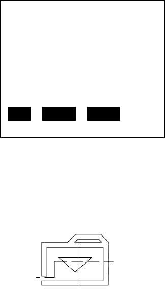
When there are more peers connected to the ad-hoc network than just the printer, the printer
will also turn on an additional OCP icon that looks like a folder:
The folder icon is useful to determine whether another peer is connected to the same ad-hoc
network as the printer. When using the OCP Info display to see the Wireless Info, an ad-hoc
connection will display as follows:
SSID: Test
ADH:00:a0:f8:be:fe:72
Chan = 1 SIG = 52%
SEC MODE: WEP
CRYPTO: RC4
MAX SPEED: 54 Mbps
NEXT SELECT CANCEL

37
Multi-homing Considerations
The printer has both wired and wireless Ethernet interfaces that can be used at the same time.
This capability is referred to as multi-homing, where a device has multiple interfaces with a
different IP address assigned to each interface. If you intend to use this capability, care must be
taken with regard to the IP addresses assigned and whether both interfaces connect to the
same network or different networks. If instead you intend to use only one interface then the
remainder of this section doesn’t apply. It is recommended, however, that if you plan to use
only the wireless interface that you disable DHCP on the wired interface and set the wired
interface network settings (IP Address, Subnet Mask and Gateway Address) to a different
subnet than the one the wireless interface is using. This can be as simple as setting the wired
interface IP Address to: 0.0.0.0. This will prevent a wireless interface communications error if
the wired interface is plugged into a network.
The primary multi-homing issue depends upon whether both wired and wireless interfaces are
configured for the same subnet. For example, if both interfaces are configured with a Subnet
Mask of 255.255.0, the wired interface IP Address is set to 192.168.0.11 and the wireless
interface IP Address is set to 192.168.0.47, both interfaces are on the same subnet. The Subnet
Mask determines the span of the subnet. In this case, any IP Address in the range of
192.168.0.0 to 192.168.0.255 falls within the same subnet. If the wired interface IP Address was
changed to 192.168.1.11, the interfaces would be on different subnets. If the Subnet Mask was
changed to 255.255.0.0 for both interfaces, then both interfaces would be on the same subnet
again and the IP Address range for that subnet would be 192.168.0.0 to 192.168.255.255.
When both wired and wireless interfaces are configured for the same subnet and connected to
a network, the printer can no longer distinguish between the two interfaces when routing
Ethernet packets to the network. While packets are received on both interfaces, packets that
are being routed to the network are likely to be returned on the wired interface. This is because
the routing algorithm will look for the first interface available that satisfies the routing
requirements based upon the destination IP Address. Given this, both interfaces must connect
to the same network so that any host that sends packets to the printer is reachable on both
interfaces.
WIRELESS INFO
SSID: Ed2
CHAN = 5 SIG = 100%
NOISE FLOOR =-90 dBm
AD-HOC WEP RC4
54 Mbps
PREV NEXT EXIT
38
There may be occasions where it is desirable to connect the printer to two entirely separate
networks. In this scenario, the hosts on one network are not reachable through the other
network. To make this work correctly, the two networks must be on different subnets. The IP
Address and Subnet Mask settings must be properly set to achieve this. For example, if both
interfaces are configured with a Subnet Mask of 255.255.0, the wired interface IP Address is set
to 192.168.0.11 and the wireless interface IP Address is set to 192.168.1.47, both interfaces are
on different subnets. If the configuration of the printer network settings is not done correctly,
communications may fail due to packets being sent on the wrong interface. When configured
for different subnets, the printer does not provide a bridge between the two networks.
39
5 Monitor Wireless Performance
Once you have connected your printer to a wireless access point there are several ways that
you can monitor the performance. Performance monitor is important to insure that the
wireless connection is working reliably.
Wireless Info Pages
Wireless information is available through the OCP using the INFO button. Press the INFO soft-
key and the display changes to:
The revision numbers and serial numbers displayed for your printer may be different. At any
time you can press the EXIT soft-key to return to the normal status display. Press the NEXT soft-
key several times until the display changes to:
This screen provides information about the status of the wireless information and if connected
to an access point additional information. If the radio is turned off or not connected to a
wireless access point, a display such as the following will be shown:
PRINTER INFO
MCB FZ8ME.02.05.00
HCB FZ8ME.01.05.00
MAB FZ8RE.01.00.00
MSN: 06C092500013
PH S/N: 91-00254
PREV NEXT EXIT
WIRELESS INFO
SSID: Ed2
CHAN = 5 SIG = 100%
NOISE FLOOR =-90 dBm
WPA2 CCMP
54 Mbps
PREV NEXT EXIT
WIRELESS INFO
RADIO OFF
PREV NEXT EXIT
40
The “RADIO OFF” status location may be populated with one of several strings as shown in the
following table:
Radio Status
Description
RADIO OFF The radio is turned off.
RADIO DISCONNECTED The radio has not yet started the process of connecting to an access
point or the link with the access point has been lost. The radio will
shortly attempt to reconnect.
RADIO INACTIVE The radio is inactive because the association with an access point
failed.
RADIO CONNECTING The radio is in the process of connecting to an access point
(scanning, associating or key handshaking).
When connected to an access point, the display shows the SSID of the access point, the wireless
channel, the current signal strength in percent, the noise floor, the security mode, the type of
encryption being used (if applicable) and the current data rate that recent packets have been
received with.
Signal Strength
In addition to the signal strength value available on the Wireless Info screen, the printer also
uses an antenna icon on the OCP to indicate signal strength. The antenna icon has a body and
four bars associated with it. Thus five separate icon states are available from no bars (just icon
body) to four bars. The signal strength is based upon the SNR (Signal to Noise Ratio) with which
data packets are being received by the radio. The SNR is translated into a percentage in order to
make the number more intelligible to the user. For those that are interested, the SNR can be
derived from the signal strength in percent by using this equation:
SNR (dB) = 40 * Signal Strength (%) / 100
The following table outlines the SNR bands that are used to determine how many bars to
display for the antenna icon:
SNR (dB)
Bars
Signal
Strength %
Quality
40 and above
4
100
Robust connection, always fast.
25 to 39.99
3
62 - 99
Robust connection, mostly fast.
15 to 24.99
2
37 - 61
Robust connection, usually fast.
5 to 14.99 1 12 -36 Connection slow with packet resends and
intermittent loss of link.
0 to 4.99
0
0 - 11
Insufficient signal to connect.
0 - blinking Connection in progress.
41
It is very important to recognize that good signal strength is absolutely necessary for reliable
operation. Signal strength below 25% is likely to cause problems. Signal strength above 50% will
provide robust operation. Signal strength is not merely a factor of the distance between the
printer antenna and the access point antenna. Other factors such as ambient noise, intervening
walls and other nearby wireless equipment can result in poor signal strength. See the
Troubleshooting chapter for suggestions for improving signal strength.
Noise Floor
The noise floor is an instantaneous measure of the ambient noise that the wireless radio sees
when it is not transmitting or receiving a packet. There is always ambient thermal noise at a
level of -100 dBm that cannot be avoided. Added to this is manmade noise coming from:
microwave ovens, cordless telephones, baby monitors, wireless cameras, remote car starters,
DECT and residential wireless phones and Bluetooth products to name just a few. When you
add the noise sources together, the typical noise floor the wireless radio should see is
approximately -90 ±5 dBm. A more negative number is better (-95 is less noise than -90). The
noise floor value can be useful to evaluate whether the ambient noise is too high for robust
wireless operation. If the noise floor is higher than -85 dBm, then you may want to take steps to
reduce the noise level the wireless radio sees (see the Troubleshooting chapter). By using the
Signal Strength and Noise Floor values, the actual signal level can be calculated as follows:
Signal Level (dBm) = Noise Floor (dBm) + (40 * Signal Strength (%) / 100)
Data Rate
The data rate shown in the Wireless Info display can provide some insight into how well the
wireless interface is working. When there is a good SNR, the radio should typically show the
maximum data rate the router can support (11 Mbps for 802.11b and 54 Mbps for 802.11g).
You may notice at times that lower speeds are displayed. This is expected as long as the
maximum speed appears most of the time, particularly when a print job is being received.
When the SNR is poor, data will be sent at a slower speed to improve the signal quality
(receiver sensitivity is better at slower data rates). If you consistently see a low data rate, then
you may want to take steps to improve the signal quality (see Troubleshooting chapter).
DHCP & MAC Address Info Page
Using first the INFO button then the NEXT button, go to the next page after the Wireless Info
page shown above. The display should look like:
42
This screen shows the DHCP state, which can be Enabled or Disabled. If enabled, the screen can
show one of the states shown in the following table:
State
Description
DHCP WAIT
Waiting for DHCP to be ready.
DHCP INITIALIZING DHCP initializing.
DHCP: Request Sent Request sent to DHCP server.
DHCP Timeout Timeout due to no response to request.
If DHCP is disabled or the printer has received a response from a DHCP server, the Info Page
displays the current IP Address, Subnet Mask and Default Gateway Address. The last line of the
display shows the MAC Address of the wireless interface (different from the wired interface).
Wireless Statistics Info Page
Pressing the NEXT soft-key again will display the Wireless Statistics screen, as follows:
The RX Bytes value is the total number of bytes that have been received by the printer from the
radio. The number of discards represents the number of RX packets that were discarded
because there was no buffer available to receive the packet. This should almost always be zero.
A discard is not a hard failure as the packet will be resent by the sender at a later time. The TX
Bytes value is the total number of bytes that have been sent by the printer to the radio. The
number of discards represents the number of TX packets that were discarded because the
packet was malformed or dropped due to a communication error with the radio. This should
almost always be zero. A discard is not a hard failure as the packet will be resent by the printer
at a later time. The final value is a catchall error counter for errors. This should be zero as it
indicates a hard error. A non-zero error counter may mean that there is a hardware failure. The
wireless statistics counts are reset to zero on power-up.
WIRELESS INFO
DHCP Enabled
IP: 192.168.0.100
Mask: 255.255.255.0
GW: 192.168.0.1
MAC:00:19:88:06:4f:87
PREV NEXT EXIT
WIRELESS STATISTICS
RX BYTES: 18862
DISCARDS: 0
TX BYTES: 361
DISCARDS: 0
ERRORS: 0
PREV NEXT EXIT
43
Wireless Statistics Success and Failure Rates
Pressing the NEXT soft-key again will display the Wireless Statistics Success and Failure Rates
screen, as follows:
The meaning of these values is described in the following table:
Statistic Name
Description
TX SUCCESS The percentage of packets successfully transmitted by the printer’s radio. A
higher number is better.
TX RETRY
The percentage of packets that need to be retransmitted. A lower number is
better. A retry happens because the access point failed to receive the
packet correctly.
RX SUCCESS The percentage of packet successfully received by the radio. A higher
number is better. A packet receive fails due to a Frame Check Sequence
error, meaning the packet was corrupted during transmission.
RX DUPLICATE The percentage of frames that are received more than one. A lower number
is better. This can happen if the access point does not receive an ACK from
the printer for the original frame.
RTS SUCCESS The percentage of times in which CTS is received in response to an RTS.
Higher is better.
The above numbers do not represent hard failures. Under normal circumstances, Success rates
will be lower than 100% and the Retry & Duplicate rates will be higher than 0%. These rates do
provide some information about the quality of the link. If you see low TX/RX Success Rates or
high Retry/Duplicate Rates, you may be experiencing an unacceptably high error rate and need
to take steps to improve the link quality (see Troubleshooting chapter). The statistics are
cleared only when the printer is powered up.
Main Status Display Wireless Errors
During normal operation the OCP displays the printer status, such as the following:
WIRELESS STATISTICS
TX SUCCESS = 100%
TX RETRY = 6%
RX SUCCESS = 96%
RX DUPLICATE = 0%
RTS SUCCESS = 67%
PREV NEXT EXIT
44
If the wireless interface is experiencing hard errors, an indication of this will be added to the
normal status display, such as the following:
A wireless error is not considered an alarm condition, such as “Out of Cards”, so the display
does not change to ALARM. The wireless error display is simply informative. In most cases
communications with the printer will have been lost, so the wireless error condition will not be
seen by a host. The wireless errors are detailed in the following table:
Wireless Error Text
Code
Description
WIFI ACCESS POINT
MISSING
19002 After power up, the printer tried to connect to the access point
specified by the wireless settings, but the access point was not
found during the scan. The printer will periodically retry to
connect to the access point.
WIFI LINK LOST 19003 The connection to the access point was lost. This may be due to
poor signal strength, interference or the access point power has
been lost. The printer will periodically retry to connect to the
access point.
WIFI INCOMPATIBLE
NETWORK
19004 After power up, the printer tried to connect to the access point
specified by the wireless settings, but found the access point
settings incompatible. This could occur if the access point
configuration is modified. To correct, re-run the Setup Wizard
to establish new wireless settings.
WIFI ASSOCIATION
FAILED
19005
During association with an access point, the association failed.
This could be a result of poor signal quality. If the signal
strength is low, take steps to improve it, then re-run the Setup
Wizard to establish new wireless settings.
WIFI CONNECTION
FAILED
19006 The key handshake following the association failed. This may be
because the WEP key or WPA passphrase is wrong. To correct,
make sure that you have the correct key passphrase then re-run
the Setup Wizard to establish new wireless settings.
READY
MENU INFO
READY
WIFI LINK LOST
ERROR CODE = 19003
MENU INFO
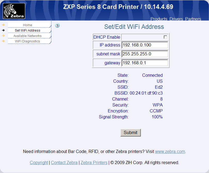
45
Viewing Wireless Information through Printer Web Page
From the home web page, click Wireless Parameters, the following page is displayed:
Note that the same information available from OCP Wireless Info pages is available in this web
page. Now click WiFi Diagnostics to get the following web page:
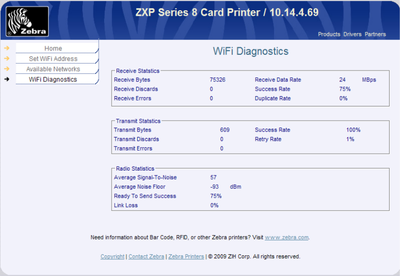
46
Viewing Wireless Information through Windows Printer Driver Toolbox
Open the ZXP Toolbox and under the Information section, click on Wireless Network. The
following screen will be displayed:

47
This screen provides some additional information not available through the OCP or printer web
page:
RSSI – received signal strength indicator. The strength of the received signal in dBm.
SNR – the signal to noise ratio in dB for the received signal.
Link lost – the number of times the connection to the access point has been lost.
Unicast packets – the number of unicast packets that have been sent or received.
Non unicast packets – the number of non unicast packets that have been sent or received.
Mcasttxframe - Increments when the multicast bit is set in the destination MAC address of a
successfully transmitted MSDU.
48
Failed - Increments when an MSDU is not transmitted successfully.
Retry - Increments when an MSDU is successfully transmitted after one or more
retransmissions.
Multiretry - Increments when an MSDU is successfully transmitted after more than one
retransmission.
Framedup - Increments when a frame is received that the Sequence Control field is indicating
a duplicate count. Happens if the AP failed to receive an ACK from the STA for the original
frame.
Rtssuccess - Increments when a CTS is received in response to an RTS.
Rtsfailure - Increments when a CTS is not received in response to an RTS.
Ackfailure - Incremements when an ACK is not received when Expected. The number of
MMPDUs and MPDUs unacknowledged by the peer.
Rxfrag - Increments for each successfully received MPDU of type Data or Management.
Mcastrxframe - Increments when a MSDU is received with the multicast bit is set in the
destination MAC address of a successfully.
Fcserror - Increments when a Frame Check Sequence error (FCS) is detected in a received
MPDU. Due to wireless link interference.
Txframe - Increments for each successfully transmitted MSDU.
At the bottom of the ZXP Toolbox Wireless Network page there is a Save button. Pressing this
button will save all of the data displayed on this page to two XML files. This may be useful as a
diagnostic tool if you are having problems with the wireless connection. These XML files can be
emailed for analysis.
49
6 Troubleshooting
Wireless Troubleshooting Checklist
Before beginning to troubleshoot the wireless printer, verify the following:
• The power cord is connected to the printer, and the printer is on.
• The antenna is attached to the printer.
• Your SSID is correct. If you are not sure if your SSID is correct, run the wireless setup
wizard again.
• Your WEP key or WPA passphrase is correct. Log into the wireless access point (wireless
router) and check the security settings. A security key is like a password. All devices on
the same wireless network using WEP, WPA, or WPA2 share the same security key. If
you are not sure if your security information is correct, run the wireless setup wizard
again.
• The wireless network is working properly. Try accessing other computers on your
wireless network. If your network has Internet access, try connecting to the Internet
over a wireless connection.
• The printer is within the range of the wireless network. For most networks, the printer
should be within 100 feet (30 meters) of the wireless access point (wireless router).
• The printer is located away from obstacles that could block the wireless signal. Remove
any large metal objects between the access point and the printer. Make sure the printer
and wireless access point are not separated by poles, walls, or support columns
containing metal or concrete.
• The printer is located away from other electronic devices that may interfere with the
wireless signal. Many devices can interfere with the wireless signal, including baby
monitors, motors, cordless phones, security system cameras, other wireless networks,
and some Bluetooth devices.
• The printer driver is installed on the computer from which you are performing a task.
• The correct printer port is selected.
• The computer and printer are both connected to the same wireless network.
50
Cannot Print Over Wireless Network
If you encountered problems while installing, or if your printer does not appear in the printers
folder or as a printer option when sending a print job, you can try uninstalling and reinstalling
the software.
These are possible solutions. Try one or more of the following:
1. Make Sure Your Computer Is Connected To Your Wireless Access Point
• See if you have access to the Internet by opening your Web browser and accessing
any site.
• If there are other computers or resources on your wireless network, check to see if
you can access them from your computer.
2. Move the Computer and/or Printer Closer To the Wireless Router
Although the possible distance between devices in 802.11b or 802.11g networks is 300
feet, the maximum range for optimal performance is generally 100–150 feet.
3. Move Your Access Point to Minimize Interference
There may be temporary interference from other devices such as microwave ovens or
other appliances, cordless phones, baby monitors, and security system cameras. Make
sure your access point is not positioned too closely to these devices.
4. Check Whether the Printer Is On the Same Wireless Network as The Computer
The SSID of the printer must match the SSID of the wireless network. Type the IP
address of the wireless access point (wireless router) in the Web address field of your
browser. If you do not know the IP address of the wireless access point start with item a.
If you know your access point IP address, start with f:
a. Click Start.
b. Click All Programs or Programs->Accessories->Command Prompt.
c. Type ipconfig.
d. Press Enter.
e. The “Default Gateway” entry is typically the wireless access point. The IP address
appears as four sets of numbers separated by periods, such as 192.168.0.100.
Your IP address might also start with the numbers 10 or 169. This is determined
by your operating system or wireless network software.
51
f. Type the router IP address into your browser. Type your user name and
password for the wireless access point (wireless router) when prompted and
Click OK.
g. On the main page, click Wireless or another selection where settings are stored.
The SSID appears. Write down the SSID, security type, and the security keys if
they are shown. Note: Make sure you copy them down exactly, including any
capital letters. Store the SSID and the security keys in a safe place for future
reference.
5. Check Your Security Keys
A security key is like a password. All devices on the same wireless network must share
the same security key.
WEP key
Exactly 10 or 26 hexadecimal characters. Hexadecimal characters are A-F, a-f, and 0-9.
WPA or WPA2 passphrase or key
From 8 to 63 ASCII characters. ASCII characters in a WPA passphrase are case-sensitive.
The currently recommended minimum length for a passphrase is twenty characters.
Note: If you do not know this information, see the documentation that came with the
wireless network, or contact the person who set up your wireless network.
6. Check Your Advanced Security Settings
• If you are using MAC address filtering to limit access to your wireless network,
you must add the printer MAC address to the list of addresses allowed to
connect to the wireless access point.
• If you set the wireless access point to issue a limited number of IP addresses, you
must change this so that the printer can be added.
Note: If you do not know how to make these changes, see the documentation that came
with the wireless network, or contact the person who set up your wireless network.
7. Ping the Access Point to Make Sure the Network Is Working
If you do not already know it, find the IP address of the access point.
a. Click Start.
52
b. Click All Programs or Programs ->Accessories->Command Prompt.
c. Type ping followed by a space and the IP address of the wireless access point. For
example:
ping 192.168.0.100
d. Press Enter.
e. Check to see whether the access point responds:
• If the access point responds, you will see several lines appear that start with
“Reply from.” It is possible that the printer did not connect to the wireless
network. Turn off and then restart the printer to try to connect again.
• If the access point does not respond, it will take several seconds and then you
will see “Request timed out.” You will need to take steps to repair the
connection between the PC and the wireless network.
8. Ping the Printer to See if it is Accessible
Use the INFO and NEXT soft-keys on the OCP to display the wireless IP Address. As
shown above, print the printer with this address. If a timeout results, then the printer is
not connected to the wireless network.
Improve Wireless Signal Strength
A common reason wireless printers fail to communicate over a network is poor wireless signal
quality. If the signal is too weak, too distorted, or blocked by an object, it cannot carry
information between the access point and the printer. To determine if the printer is receiving a
strong signal from the access point, Use the INFO and NEXT soft-keys on the OCP to display to
display the Wireless Info pages and Statistics. The Signal Strength and Noise Floor values may
indicate poor signal strength or noisy environment. Drops in signal strength can be intermittent,
however, and although the signal quality appears high, it may drop during certain conditions.
If you think signal strength is a problem between your access point and the printer, try one or
more of the following:
1. Move the Printer Closer to the Wireless Access Point
If the printer is too far away from the access point, it will not be able to communicate
with other devices on the network. For most indoor wireless networks, the maximum
distance between the access point and the printer is approximately 100 feet (30
meters). This distance could be longer or shorter, depending upon the layout of the
network and the limitations of the access point.
53
2. Remove Obstacles between the Access Point and the Printer
The wireless signal from your access point will pass through most objects. Most walls,
floors, furniture and other objects will not block the wireless signal. However, there are
materials that are too dense for the signal to pass through. Objects containing metal
and concrete can block the signal, including:
• Cubicle walls
• Ducts
• Window frames
• Poles and interior support columns
• Metal office furniture and cabinets
• Elevators
• Steel doors
• Walls and other structural elements reinforced by rebar
Arrange your printer and access point so that the signal is not blocked by any of these
objects.
3. Remove Sources of Interference
Other types of radio frequencies can cause problems with the wireless signal on your
network. These sources of interference can cause printing issues that seem to come and
go. Some common sources of interference are:
• Cordless phones
• Microwave ovens
• Refrigerators and other appliances
• Bluetooth devices
• Other wireless networks
• Motors
Turn off these potential sources of interference where possible. Avoid using microwaves
and cordless phones when printing over your wireless network.
If another wireless network is operating in the vicinity, change the wireless channel on
the access point.
Do not place your access point on a printer. Printers can also interfere with the wireless
signal.
54
4. Arrange the Network to Reduce Signal Absorption
Even when the wireless signal is able to pass through an object, it is slightly weakened. If
it passes through too many objects, it can be significantly weakened. All objects absorb
part of the wireless signal when it passes through them, but certain types of objects
absorb enough to cause communications problems. To avoid signal absorption, avoid
placing the following items between your access point and your printer:
• Stacks of paper or books
• Multiple walls or floors
• Crowds of people
• Objects containing water, such as fish tanks
• Plants
Place your access point as high in the room as possible to avoid signal absorption.
5. Add Addition Access Point
If the access point is too far away from the printer or the current access point has too
many wireless clients attached to it, try adding a second wireless access point to your
network that is closer to the printer. Make sure that you use different channels for the
two access points.
6. Conduct Site Survey
The location of your wireless network may have too many access points within range of
the printer. Access points on the same or adjacent channels can interfere with each
other, causing reduced signal strength, retries and corrupted packets. To find out about
the access points in the area, use a tool such a NetStumbler or InSSIDer. NetStumbler
(also known as Network Stumbler) is a tool for Windows XP (Vista and Windows 7 not
yet supported) that facilitates detection of Wireless LANs using the 802.11b, 802.11a
and 802.11g WLAN standards. It will provide information on access points found, the
channels they are using and the signal strength. Armed with this information, you may
be able to reconfigure your wireless network to reduce interference and improve signal
strength.

55
7 Technical Specifications
The wireless interface complies with IEEE 802.11-2007 with exceptions noted below:
IEEE 802.11 Standards
Standard
Supported
Description
802.11a N 54 Mbps, 5 GHz standard
802.11b Y Enhancements to 802.11 to support 5.5 and 11 Mbps
802.11d N International (country-to-country) roaming extensions
802.11e N Enhancements: QoS, including packet bursting
802.11g
Y
54 Mbps maximum rate, 2.4 GHz standard
802.11h
N
Spectrum Managed 802.11a (5 GHz) for European compatibility
802.11i
Partial
Enhanced security (see Securities table below)
802.11j
N
Extensions for Japan
Securities
Security
Supported
None
Y
WEP (40 & 104 bit) – Only Open Authentication
Y
WPA-PSK (Personal) Y
WPA2-PSK (Personal) Y
EAP-FAST N
EAP-FAST with Auto-provisioning
N
EAP-TLS
N
EAP-TTLS
N
LEAP N
PEAP V0 with MS-CHAP V2 N
WPA-LEAP N
WPA-EAP-FAST N
WPA-EAP-FAST with Auto-provisioning
N
WPA-EAP-TLS
N
WPA-EAP-TTLS
N
WPA-PEAP V0 with MS-CHAP V2 N
WPA2-LEAP N
WPA2-EAP-FAST N
WPA2-EAP-FAST with Auto-provisioning N
WPA2-EAP-TLS
N
WPA2-EAP-TTLS
N
WPA2-PEAP V0 with MS-CHAP V2
N

56
Network Stack Protocols
Protocol Description Supported
IPv4 Internet Protocol Y
IPv6
Internet Protocol
Y
Raw TCP Port 9100
Transmission Control Protocol
Y
Raw UDP Port 9100
User Datagram Protocol
Y
FTP Client File Transfer Protocol N
ICMP Internet Control Message Protocol Y
FTP Server File Transfer Protocol N
DHCP Client Dynamic Host Configuration Protocol Y
DHCP Options
N
DHCP Address Retention
When the printer reboots, if it had previously
acquired a DHCP IP address it will provide that
address in a DHCP request packet to the server.
It is expected that if the address is still available then
the server will provide it back to the printer.
Y
BOOTP Client Bootstrap Protocol N
ARP Client
Address Resolution Protocol
Y
RARP Client
Reverse Address Resolution Protocol
N
Gleaning (PING)
Method of specifying IP address by pinging
N
Static IP Manual assignment of IP address Y
DNS Domain Name System N
WINS Windows Internet Naming Service N
ESI Discovery
N
ESI Multicast address
N
Auto IP
Server-less dynamic IPv4 address assignment
N
LPR/LPD Line Printer Remote protocol /Line Printer Daemon
protocol
N
IPP v1
Internet Printing Protocol
N
IPP v2
Internet Printing Protocol
N
SSH Secure Shell N
SSL Secure Sockets Layer N
IP Access Control N
IP Filtering N
IPSec
Internet Protocol Security
N
Fast IPSec
N
IKE
Internet Key Exchange
N
Open Crypto N
SNMP v1 Simple Network Management Protocol Y
SNMP v2 Simple Network Management Protocol Y
SNMP – Traps
N
HTTP Server
Y

57
HTTP static pages Y
HTTP HTML Y
NTP Client Network Time Protocol N
Telnet Configuration
N
POP3 Client
Post Office Protocol
N
POP3 attachments
N
SMTP Client Simple Mail Transfer Protocol N
SMTP Alerts N
TFTP Sever Trivial File Transfer Protocol N
Other Features
Feature
Specification
Roaming Not Supported
Fast Re-association Not Supported
CCX v3 Not Supported
CCX v4 Not Supported
CCX v5
Not Supported
Ad-Hoc Network (IBBS)
Supported (Security NONE or WEP only)
Data Rates
1, 2, 5.5, 11, 6, 9, 12, 18, 24, 36, 48 and 54 Mbps
Frequency Range 2.401 to 2.495 GHz
Receive Sensitivity
-90 dBm (1, 2, 5.5, 6 Mbps)
-88 dBm (9, 11, 12 Mbps)
-87 dBm (18 Mbps)
-83 dBm (24 Mbps)
-75 dBm (48 Mbps)
-74 dBm (54 Mbps)
Transmit Output Power
10 dBm
External Antenna Type
Reverse SMA plug connector, 1 dBi gain
The wireless radio ships from the factory configured for one of three possible regions. The
region cannot be changed by the user. The region determines the channel utilization. For all
three regions, the maximum power output for any channel is 10 dBm as specified above. The
following table defines the regions, channel utilization and countries which are included in the
region:

58
Region Channels Countries
USA 1 – 11 Canada, Colombia, Dominican Republic, Grenada, Guatemala,
Guam, Mexico, Panama, Puerto Rico, Taiwan, United States,
Uzbekistan
EUROPE
1 – 13
United Arab Emirates, Armenia, Netherlands Antilles, Austria,
Australia, Aruba, Azerbaijan, Bosnia & Herzegovina, Barbados,
Belgium, Bulgaria, Bahrain, Saint Barthelme, Brunei,
Darussalam, Belarus, Switzerland, Chile, China, Costa Rica,
Cyprus, Czech Republic, Germany, Denmark, Ecuador, Estonia,
Egypt, Spain, Finland, France, Georgia, Great Britain, Greece,
Greenland, Honduras, Hong Kong, Croatia, Haiti, Hungary,
Indonesia, Ireland, Israel, India, Iceland, Iran, Italy, Jamaica,
Jordan, Cambodia, North Korea, Kuwait, Kazakhstan, Lebanon,
Liechtenstein, Sri Lanka, Lithuania, Luxembourg, Latvia,
Monaco, Morocco, Macao, Macedonia, Malta, Netherlands,
Norway, Nepal, Oman, Peru, Papua New Guinea, Philippines,
Pakistan, Poland, Portugal, Qatar, Romania, Russian
Federation, Saudi Arabia, Sweden, Singapore, Slovenia,
Slovakia, El Salvador, Syrian Arab Republic, Thailand, Trinidad
& Tobago, Tunisia, Turkey, Ukraine, Uruguay, Vietnam, Yemen,
South Africa, Zimbabwe, Albania, Argentina, Brazil, Algeria,
South Korea, Malaysia, Bolivia, Belize, New Zealand, Venezuela
JAPAN
1- 13
Japan (channel 14 not available)
59
8 Glossary
10/100 Base-T
A technical term for Ethernet. 10/100 refers to the speed at which the Ethernet network
functions. 10 indicates 10 megabits per second (Mb/s) for normal Ethernet, and 100 indicates
100 Mb/s for Fast Ethernet.
802.11a
A type of wireless networking that provides up to 54 Mbps transmission in the 5 GHz band.
802.11b
A type of wireless networking that provides up to 11 Mbps transmission (with a fallback to 5.5,
2 and 1 Mb/s) in the 2.4 GHz band.
802.11g
A type of wireless networking that provides up to 54 Mbps transmission in the 2.4 GHz band.
Ad-hoc network
A type of wireless network in which devices directly communicate with each other rather than
through a Wireless Access Point (WAP). Also referred to as peer-to-peer. Ad-hoc networks are
typically small and simple, for example, a wireless PC and a wireless printer. Ad-hoc networks
are independent basic service stations (IBSS), or direct-connect wireless networks.
Authentication
Authentication is a wireless network security strategy. On a network with authentication,
devices use a shared key as a password and communicate only with devices that know the key.
Unlike WEP, authentication does not encrypt the data sent between wireless devices. However,
authentication can be used in conjunction with WEP. Authentication keys and WEP keys can be
identical.
AutoIP
A process by which a device on a network automatically assigns an IP address to itself.
BOOTP
Bootstrap Protocol (BOOTP) is an Internet protocol that enables a device to discover its own IP
address, the IP address of a BOOTP server on the network, and a file to be loaded into memory
to boot the machine. This enables the device to boot without requiring a hard or floppy disk
drive.
Broadcast packet
A packet sent from one device on a network to all devices on the network.
BSS (Basic Service Set)
Basic Service Set describes the type of wireless network that you are using. The BSS type can be
one of the following: Infrastructure network or Ad-Hoc network.
Channel
A specific radio frequency used by two or more wireless devices to communicate with each
other. All devices on the network must use the same channel. The number of channels available
varies by country/region.
60
dBm
The power ratio in decibels (dB) of the power referenced to one milliwatt (mW). Examples: 0
dBm = 1 milliwatt, 10 dBm = 10 milliwatt and 20 dBm = 100 milliwatt.
DHCP (Dynamic Host Configuration Protocol)
A protocol used to automatically assign an IP address to each device on a network.
DHCP IP address
An IP address automatically assigned by a DHCP server.
DHCP server
A computer or router that gives a unique IP address to each device on the network from a
dynamically manages a pool of IP addresses. Unique addresses prevent conflicts. When a user
logs in, the server “loans” the user an IP address for the duration of the network connection.
When a user logs off, the IP address is returned to the pool for use by another device.
Digital Certificate
An electronic means of proving the identity of a network user or device. Certificates contain
detailed information about the user's device in a standard format. Digital certificates are
typically issued by a trusted third-party Certificate Authority (CA). Locally administered, or self-
signed, certificates are valid in some instances.
EAP
Extensible Authentication Protocol (EAP) is a general protocol for authentication that also
supports multiple authentication methods, such as token cards, one-time passwords,
certificates, and public key authentication.
Encryption keys
A sequence of characters or digits that a wireless device uses to encode data. Encryption keys
can be static (as they are in WEP) or dynamic (as they are in WPA).
Encryption
A network security that encodes the data sent across a wireless network making the data
unintelligible to unauthorized users. The printer supports WEP and WPA.
Ethernet
A popular form of wired computer networking for Local Area Networks.
EWS (embedded Web server)
A server that is completely contained within a device. An EWS provides management
information about the device. This is helpful for managing single devices on a small network. By
using a Web browser to access an EWS, network users can perform such operations as
obtaining network printer status updates, simple troubleshooting and changing device
configuration settings.
Firewall
A combination of hardware and software tools that protects a network from unwanted entry.
Gateway
A dedicated device (router or computer) that connects two different networks. For example, a
computer on an Ethernet network may act as a gateway between the network and the Internet.
Infrastructure network
A type of wireless network in which devices communicate with each other through a Wireless
Access Point (WAP), such as a wireless network hub, router, or gateway.
61
IP address (Internet Protocol address)
Each computer that connects to a network or the Internet, must have a unique address. IP
address numbers are in the form x.x.x.x—for example, 169.254.100.2. Most networks use DHCP
or AutoIP to dynamically assign IP addresses. However, a device can be manually assigned a
static IP address.
LAN (Local Area Network)
A high-speed type of computer network that connects devices that are a relatively short
distance from one another. An Ethernet network is one type of LAN.
MAC (Media Access Control) address
A hardware address that uniquely identifies each device on a network. You can usually find the
MAC address printed on the device.
MAC filtering
A method of limiting access to your wireless network by specifying which MAC addresses may
communicate on the network. This setting may be specified on wireless routers or access
points.
Mbps (megabits per second)
The measure for the rate at which a network functions. For example, 1 Mbps equals 1,000,000
bits per second (or 125,000 bytes per second).
Network adapter/card
A device that lets computers or printers talk to each other over a network.
Network name
A network name is an alphanumeric, case-sensitive character string that provides basic access
control to a wireless network. A network name is also known as a Service Set Identifier (SSID).
Node
A network connection point, typically a computer.
Packet
A message sent from one device on a network to other devices on the network.
Peer-to-peer
See Ad-hoc network.
Ping
A test to see if your computer can communicate with another device.
Protocol
A language that devices on a network use to communicate with each other. A popular network
protocol is TCP/IP.
Router
A device that shares a single Internet connection with multiple computers or other devices. The
basic router controls network traffic.
Router
A complex networking device that directs packets from one network to another network. A
router can act as a gateway between a LAN and the Internet.
Security key
A password, such as a WEP key or a WPA pass phrase, used to make a network secure
62
Server
A computer on a network that manages network resources. A network might have a number of
different server types. For example, a print server manages one or more printers, a file server
stores and manages files, and a network server manages network traffic.
Signal strength
Measure of how strongly a transmitted signal is being received.
SSID (Service Set Identifier)
A unique identifier (up to 32 characters) attached to the header of packets sent over a wireless
LAN. An SSID provides basic access control to a wireless network. It can also be used to logically
segment a wireless subgroup of users and devices. An SSID prevents access by any client device
that does not have the SSID. By default, an access point broadcasts it’s SSID in its beacon. An
SSID is also referred to as a Network Name because it is a name that identifies a wireless
network.
Static IP address
An IP address that is manually assigned to a device on a network. A static IP address remains
fixed until changed manually. Alternative methods for assigning IP addresses are DHCP and
AutoIP.
Subnet mask
A number that identifies the IP addresses that belong to a subnet.
Switch
A device similar to a network hub that can connect different networks together
Switch
A network device that manages network traffic in order to minimize collisions and maximize
speed.
TCP/IP
Transmission Control Protocol/Internet Protocol (TCP/IP) is the network communication
protocol used on the Internet. The printer's built-in networking feature supports LANs that use
TCP/IP.
TKIP
See WPA. Temporal Key Integrity Protocol (TKIP).
Unicast packet
A packet sent from one device on a network to another device on the network.
WEP key
A WEP key, or encryption key, is a sequence of alphanumeric characters or hexadecimal digits.
After creating a WEP key, you must remember it or store it in a secure location. You may not be
able to retrieve the WEP key if you lose it. A WEP key is either 64 or 128 bits long. The first 24
bits of the key are provided automatically. When creating the WEP key, the person creating
the key provides the remaining bits (40 bits in the case of a 64-bit key, or 104 bits in the case of
a 128-bit key).
63
WEP
Wired Equivalent Privacy (WEP) provides security by encrypting data sent over radio waves
from one wireless device to another wireless device. WEP encodes the data sent across the
network making the data unintelligible to unauthorized users. Only devices that share the same
WEP settings as the printer will be able to communicate with the printer. WEP depends on
encryption keys that are static and provides less security than WPA (TKIP).
WiFi (Wireless Fidelity)
A term used generically when referring to any type of 802.11 network, whether 802.11b/g,
802.11a, dual-band, or other. Any products tested and approved as "Wi-Fi Certified" are
certified as interoperable with each other, even if they are from different manufacturers.
Typically, however, any Wi-Fi product using the same radio frequency (2.4 GHz for 802.11b or
11g; 5 GHz for 802.11a) will work with any other Wi-Fi product, even if not Wi-Fi Certified.
Wireless Access Point (WAP)
A Wireless Access Point (WAP) is a device through which devices (for example, computers and
printers) on an infrastructure wireless network communicate with one another. A WAP is also
called a base station.
Wireless network adapter
Each node (computer or device) on the WLAN uses a wireless network adapter into which a
wireless transceiver, with a small, integrated antenna, is built. Wireless network adapters might
be internal (inserted in a computer or device), external (housed in a separate case), or built-in.
Wireless router
A router that also serves as a wireless access point
WPA (Wi-Fi Protected Access)
WPA provides security by encrypting data sent over radio waves from one wireless device to
another wireless device and by controlling access to network resources through authentication
protocols. Only devices that share the same WPA settings as the printer will be able to
communicate with the printer. WPA uses encryption keys that change frequently. WPA
provides better security than WEP. WPA typically uses TKIP encryption. WPA is not supported
on ad hoc wireless networks.
WPA2
A newer version of WPA which typically uses CCMP (AES) encryption. Older routers are less
likely to support this. Other possible security settings are WPA and WEP.
64
9 Compliance Information
Proprietary Statements
FCC Compliance Statement
This device complies with FCC Part 15 Subpart C Rules. Operation is subject to the following two conditions: (1) This device may not cause
harmful interference, and (2) this device must accept any interference received, including interference that may cause undesired operation.
Note: This equipment has been tested and found to comply with the limits for a Class A digital device, pursuant to part 15 of the FCC Rules.
These limits are designed to provide reasonable protection against harmful interference when the equipment is operated in a commercial
environment. This equipment generates, uses, and can radiate radio frequency energy and, if not installed and used in accordance with the
instruction manual, may cause harmful interference to radio communications. Operation of this equipment in a residential area is likely to cause
harmful interference in which case the user will be required to correct the interference at his own expense.
Modifications not expressly approved by the manufacturer could void the user's authority to operate the equipment under FCC rules.
WARNING: Exposure to Radio Frequency radiation. To conform to FCC RF exposure requirements this device shall be used in accordance with
the operating conditions and instructions listed in this manual. Note that there are several radio options available with this printer. Additional
regulatory information is contained in later sections devoted to each radio individually.
NOTE: This unit was tested with shielded cables on the peripheral devices. Shielded cables must be used with the unit to insure compliance.
Changes or modifications to this unit not expressly approved by Zebra Technologies Corporation could void the user’s authority to operate this
equipment.
Canadian Compliance Statement
This Class A digital apparatus complies with Canadian ICES-003.
Cet appareil numérique de la classe A est conforme á la norme NMB-003 du Canada.
“IC:” before the equipment certification number signifies that the Industry Canada technical specifications were met. It does not guarantee that
the certified product will operate to the user’s satisfaction. This device complies with Industry Canada license-exempt RSS standard(s). Operation
is subject to the following two conditions: (1) this device may not cause interference, and (2) this device must accept any interference, including
interference that may cause undesired operation of the device.
NCC (Taiwan) Compliance Statement
“經型式認證合格之低功率射頻電機,非經許可,公司、商號或使用者均不得擅自變更頻率、加大功率或變更原設計之特性及功能。低功率射頻電機之使用不得影響飛航安全及干
擾合法通信;經發現有干擾現象時,應立即停用,並改善至無干擾時方得繼續使用。前項合法通信,指依電信法規定作業之無線電通信。低功率射頻電機須忍受合法通信或工業、
科學 醫療用電波輻射性電機設備之干擾。”
“ According to “Administrative Regulations on Low Power Radio Waves Radiated Devices” Without permission granted by the DGT, any
company, enterprise, or user is not allowed to change frequency, enhance transmitting power or alter original characteristic as well as
performance to a approved low power radio-frequency devices. The low power radio-frequency devices shall not influence aircraft security and
interfere legal communications; If found, the user shall cease operating immediately until no interference is achieved. The said legal
communications means radio communications is operated in compliance with the Telecommunications Act.
The low power radio-frequency devices must be susceptible with the interference from legal communications or ISM radio wave radiated
devices.”
Contain FCC ID & IC Numbers
1. Zebra WIFI Radio 802.11b/g
FCC ID : I28-W2WLAN11G
IC ID : 3798B-W2WLAN11G

65
Radio Regulatory Information
European Regulatory Information for this Radio
This device is intended for use in all EU and EFTA member states.
Europe – EU Declaration of Conformity
This device complies with the essential requirements of the R&TTE Directive 1999/5/EC. The following test methods have been applied
in order to prove presumption of compliance with the R&TTE Directive 1999/5/EC:
Applicable Directives and S upporting S tandards:
2004/108/EC EMC Directive, EN55022:2006 Class B, EN55024:1998+A2:2003
EN61000-3-2:2006, EN61000-3-3:1995+A1:2001
2006/95/EC LVD Directive, EN60950-1:2005, CB Scheme
RLAN Enabled
Applicable Directives and S upporting S tandards:
99/5/EC R&TTE Directive, EN 301 489-17:2002, EN 300 328-3:2006
EMC requirements for spread-spectrum radio equipment.
This device is a 2.4 GHz wireless LAN transceiver, intended for indoor home and office use in all EU and EFTA member states.
WLAN Module Using 802.11b/g Radio
Other than conditions specified elsewhere in this manual, only one of the radio options can be installed in the printer at one time and the antenna used for
these transmitters must not be co-located or must not operate in conjunction with any other antenna.
European Regulatory Information for these Radios
AT BE CY CZ DK
EE
FI
FR
DE
GR
HU
IE
IT
LV
LT
LU
MT
NL
PL
PT
SK
SI
ES
SE
GB
Note: Member states in the EU with restrictive use for this device are crossed out! This device is also authorized for use in all EFTA
member states (CH, IS, LI, NO)
The use of this frequency band in France is subject to restrictions. You may only use channels 10 and 11 (2457 and 2462 MHz) on French territory, except in
those French departments as listed in the table below where channels 1-13 (2412-2472 MHz) may be used. For more information see http://www.anfr.fr/ and/or
http://www.art-telecom.fr

66
01
Ain
36
Indre
69
Rhone
02
Aisne
37
Indre et Loire
70
Haute Saone
03
Allier
39
Jura
71
Saone et Loire
05
Hautes Alpes
41
Loir et Cher
72
Sarthe
08
Ardennes
42
Loire
75
Paris
09
Ariege
45
Loiret
77
Seine et Marne
10
Aube
50
Manche
78
Yvelines
11
Aude
54
Meurthe et Moselle
79
Deux Sievres
12
Aveyron
55
Meuse
82
Tarn et Garonne
16
Charente
57
Moselle
84
Vaucluse
19
Correze
58
Nievre
86
Vienne
2A
Corse Sud
59
Nord
88
Vosges
2B
Haute Corse
60
Oise
89
Yonne
21
Cote d’Or
61
Orne
90
Territoire de Belfort
24
Dordogne
63
Puy de Dome
91
Essonne
25
Doubs
64
Pyrenees Atlantique
92
Hauts de Seine
26
Drome
65
Hautes Pyrenees
93
Seine St Denis
27
Eure
66
Pyrenees Orientales
94
Val de Marne
32
Gers
67
Bas Rhin
35
Ille et Vilaine
68
Haute Rhin