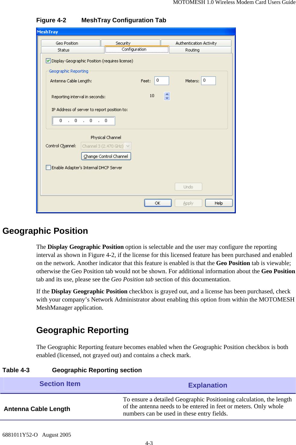
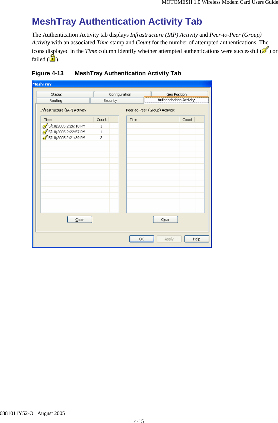
Zebra Technologies WMC73000705 Broadband Wireless Router User Manual MOTOMESH WMC Users Guide
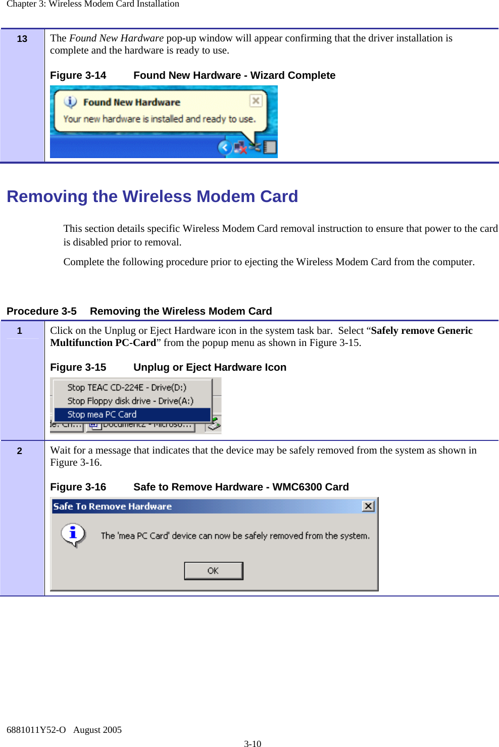
Zebra Technologies Corporation Broadband Wireless Router MOTOMESH WMC Users Guide
UserManual.wiki
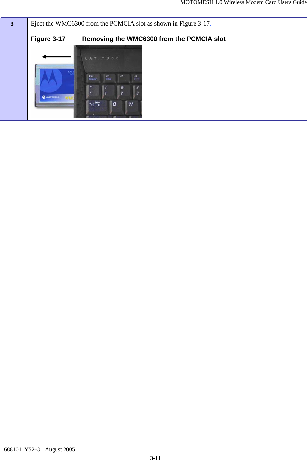
>
Zebra Technologies
>
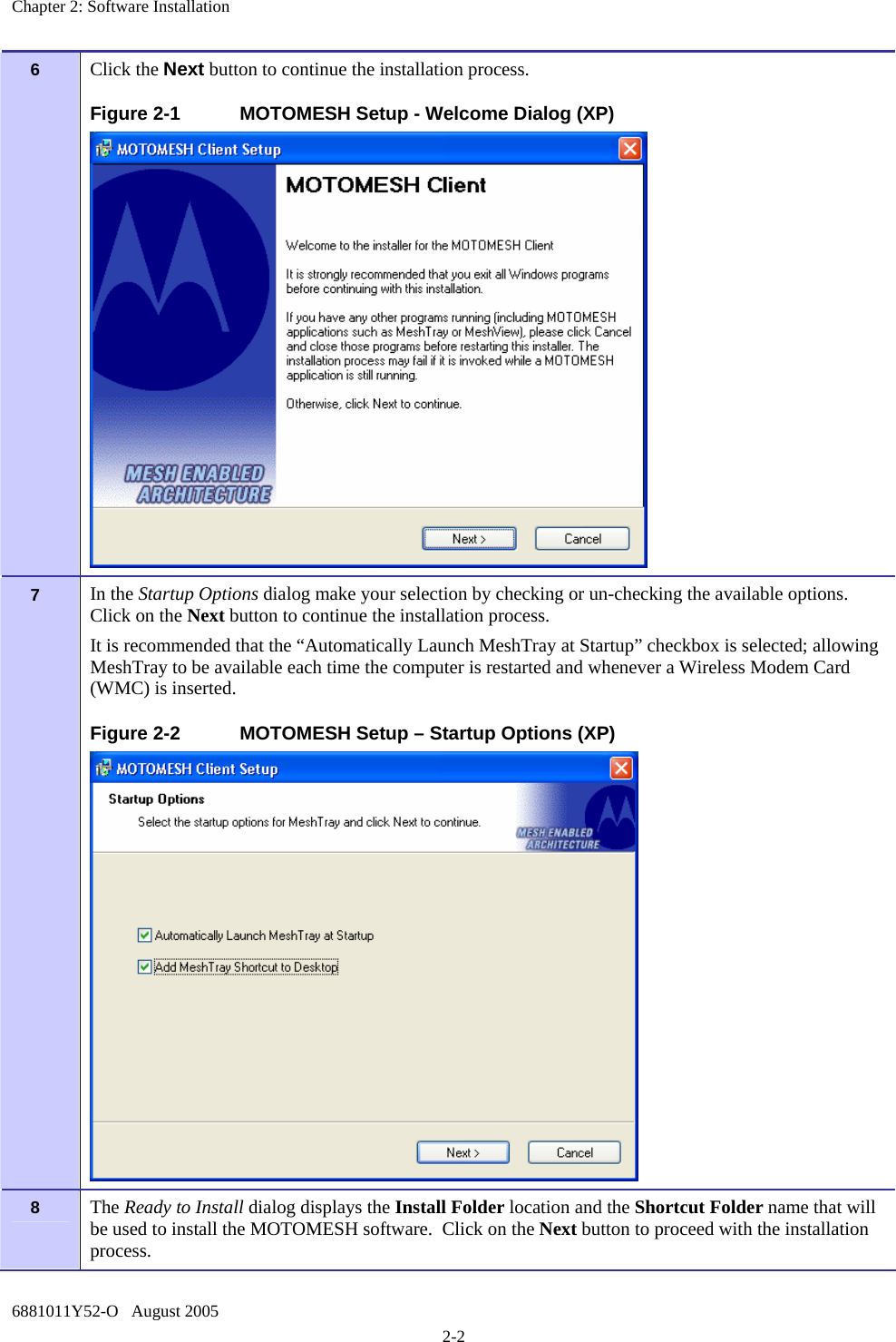
WMC73000705 User Manual
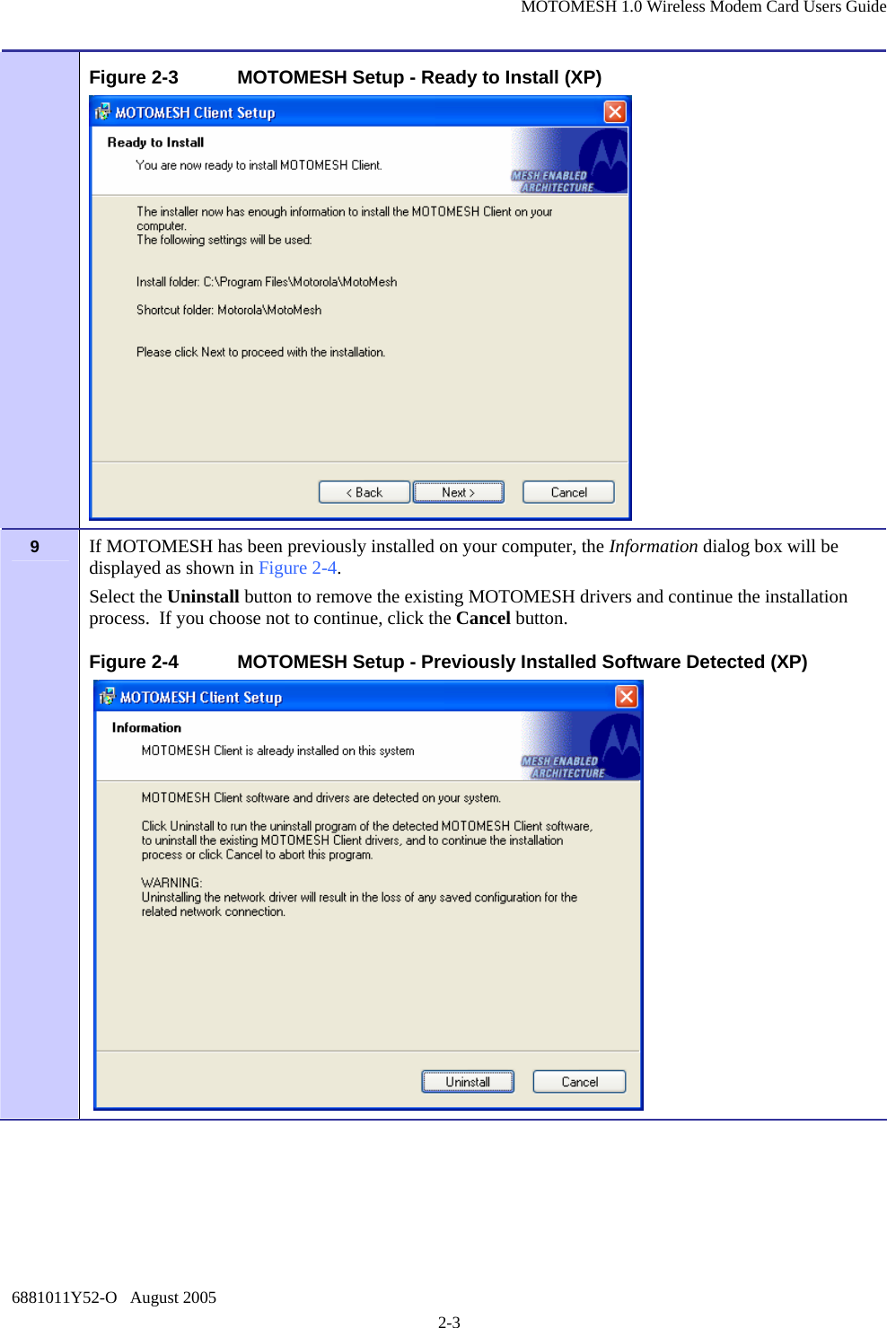
Users Guide
Navigation menu
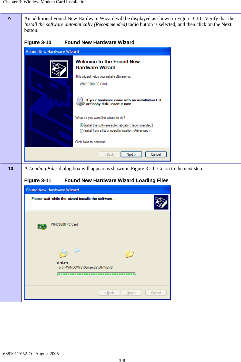
Upload a User Manual
Namespaces
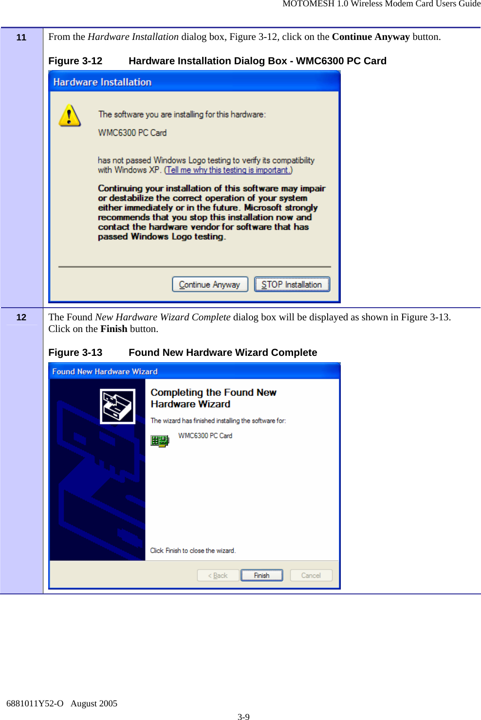
Wiki Guide
HTML
PDF
Info
Views
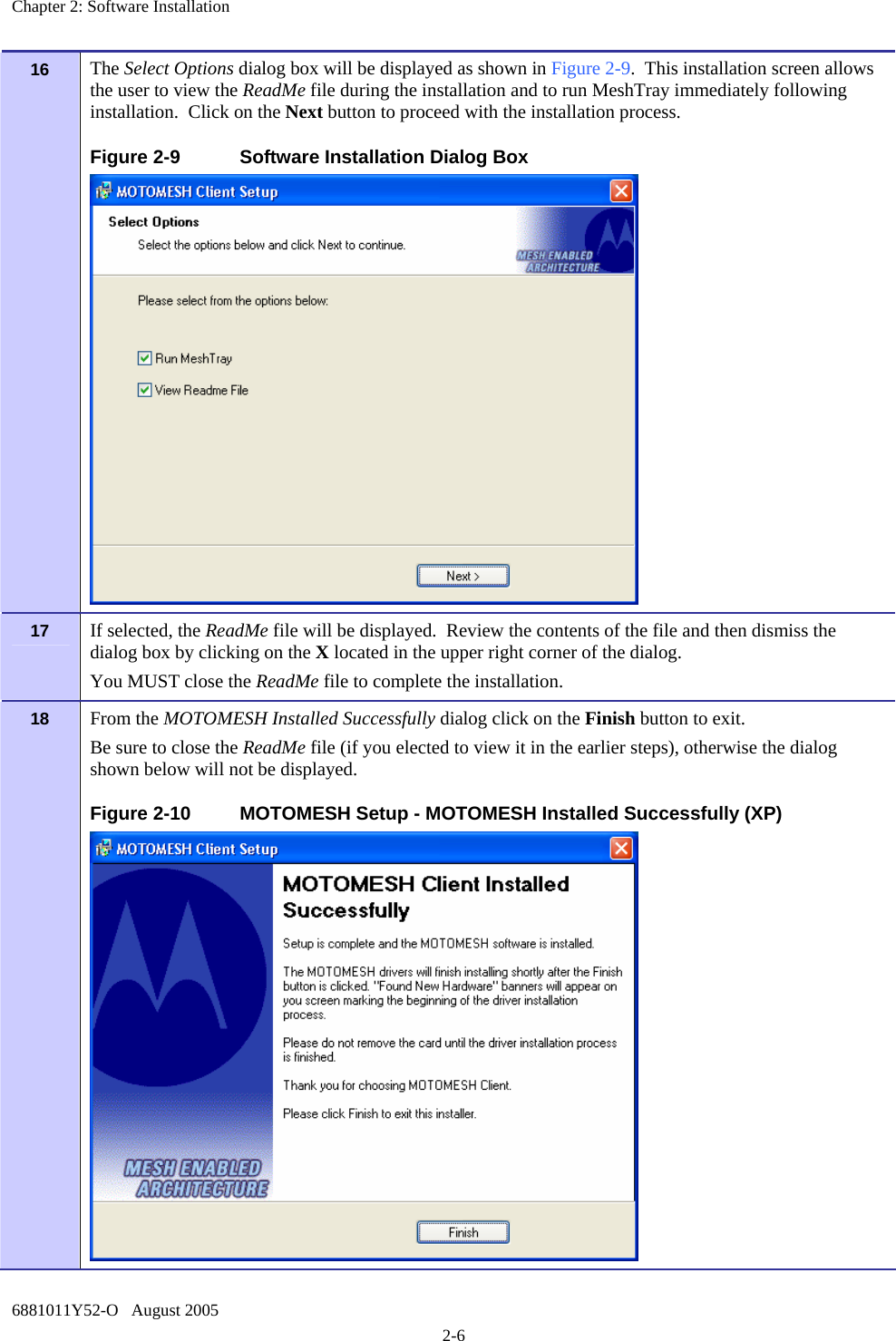
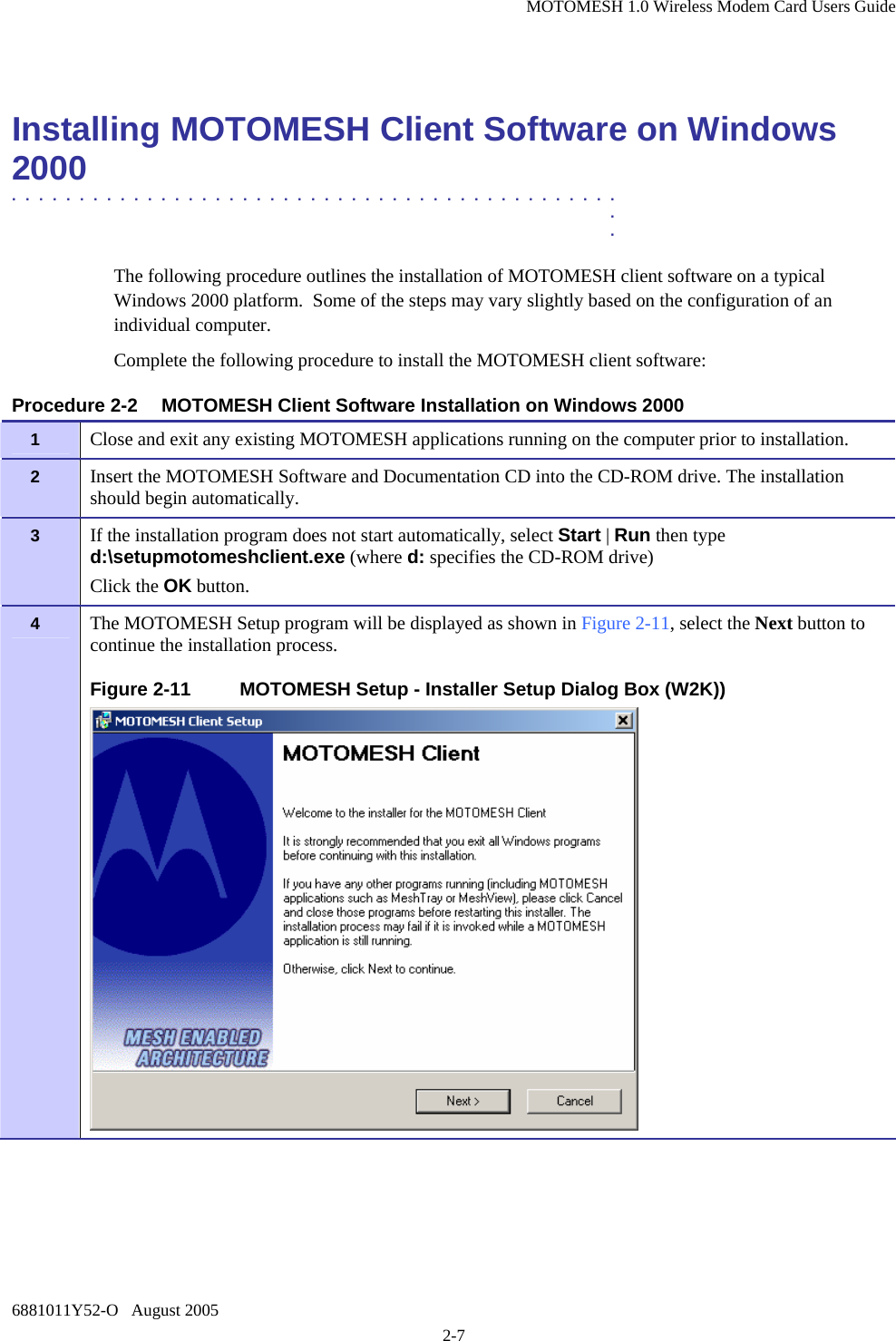
User Manual
Discussion / Help
Navigation