Zebra Technologies WMC73000705 Broadband Wireless Router User Manual MOTOMESH WMC Users Guide
Zebra Technologies Corporation Broadband Wireless Router MOTOMESH WMC Users Guide
Users Guide

MOTOMESH 4.0
Wireless Modem Card
Users Guide
August 2005
6881011Y52-O
MOTOMESH 1.0 Wireless Modem Card Users Guide
6881011Y52-O August 2005
ii
This page intentionally left blank.
MOTOMESH 1.0 Wireless Modem Card Users Guide
6881011Y52-O August 2005
iii
Copyrights
The Motorola products described in this document may include copyrighted Motorola computer programs. Laws in the United
States and other countries reserve for Motorola certain exclusive rights for copyrighted computer programs. Accordingly, any
copyrighted Motorola computer programs contained in the Motorola products described in this document may not be copied or
reproduced in any manner without the express written permission of Motorola. Furthermore, the purchase of Motorola products
shall not be deemed to grant either directly or by implication, estoppels or otherwise, any license under the copyrights, patents or
patent applications of Motorola, except for the normal nonexclusive, royalty-free license to use that arises by operation of law in
the sale of a product.
Disclaimer
Please note that certain features, facilities and capabilities described in this document may not be applicable to or licensed for use
on a particular system, or may be dependent upon the characteristics of a particular mobile subscriber unit or configuration of
certain parameters. Please refer to your Motorola contact for further information.
Trademarks
Motorola, the Motorola logo, and all other trademarks identified as such herein are trademarks of Motorola, Inc. All other
product or service names are the property of their respective owners.
Copyrights
© 2005 Motorola, Inc. All rights reserved. No part of this document may be reproduced, transmitted, stored in a retrieval system,
or translated into any language or computer language, in any form or by any means, without the prior written permission of
Motorola, Inc.
MOTOMESH 1.0 Wireless Modem Card Users Guide
6881011Y52-O August 2005
iv
This page intentionally left blank.

6881011Y52-O August 2005
v
Table
of
Contents
Contents
.............................................
.
.
.
.
Chapter 1: Introduction...........................................................................................1-1
General System Requirements.............................................................................................................................. 1-1
Windows XP Minimum System Requirements................................................................................................ 1-1
Windows 2000 Minimum System Requirements............................................................................................. 1-1
What’s in the Box............................................................................................................................................. 1-2
External Connections and LED Indicators.....................................................................................................................1-2
Chapter 2: Software Installation.............................................................................2-1
Installing MOTOMESH Client Software on Windows XP.................................................................................. 2-1
Installing MOTOMESH Client Software on Windows 2000 ............................................................................... 2-7
Chapter 3: Wireless Modem Card Installation.......................................................3-1
Prerequisite Installation Information .................................................................................................................... 3-1
Working with the Antenna.................................................................................................................................... 3-1
Connecting the Antenna Assembly.................................................................................................................. 3-1
Disconnecting a Pigtail Antenna Assembly ..................................................................................................... 3-2
Connecting the Magnetic Antenna Assembly (Optional)................................................................................. 3-3
Handling the WMC6300 and the WMC7300 ....................................................................................................... 3-4
Installing the Wireless Modem Card................................................................................................................ 3-4
Removing the Wireless Modem Card ............................................................................................................ 3-10
Chapter 4: MeshTray...............................................................................................4-1
MeshTray System Tray Icon Status...................................................................................................................... 4-1
Starting MeshTray............................................................................................................................................ 4-2
MeshTray Tab Contents........................................................................................................................................ 4-2
Status Tab......................................................................................................................................................... 4-1
Configuration Tab............................................................................................................................................ 4-2
Geographic Position.......................................................................................................................................................4-3
Geographic Reporting...............................................................................................................................................4-3
Control Channel Configuration......................................................................................................................................4-4
Changing the Control Channel .................................................................................................................................4-4
Enabling the WMCs Internal DHCP Server Feature......................................................................................................4-5
Setting a User Supplied IP Address..........................................................................................................................4-7
Configuring the DNS Address.............................................................................................................................. 4-8
Geo Position Tab.............................................................................................................................................. 4-9
MOTOMESH 1.0 Wireless Modem Card Users Guide
6881011Y52-O August 2005
vi
MeshTray Routing Tab .................................................................................................................................. 4-10
Routing Table ..............................................................................................................................................................4-11
Neighbor Table ............................................................................................................................................................4-11
Threshold.....................................................................................................................................................................4-11
Routing Icons...............................................................................................................................................................4-12
MeshTray Security Tab.................................................................................................................................. 4-13
Require Authentication to IAP Connections................................................................................................................4-13
Authentication Control for Incoming Connections.................................................................................................4-13
IAP Authentication ......................................................................................................................................................4-14
Peer Authentication......................................................................................................................................................4-14
MeshTray Authentication Activity Tab ......................................................................................................... 4-15
Chapter 5: Customer Information ..........................................................................5-1
Customer Service Information.............................................................................................................................. 5-1
Obtaining Support............................................................................................................................................ 5-1
System Information........................................................................................................................................................5-1
Return Material Request ................................................................................................................................................5-2
Radio Products and Services Division ...........................................................................................................................5-2
Radio Products and Services Division Telephone Numbers.....................................................................................5-2
Returning System Components to Motorola..................................................................................................................5-2
Returning FREs..............................................................................................................................................................5-2
Chapter 6: Certification and Safety Information...................................................6-1
FCC Regulatory Information................................................................................................................................ 6-1
FCC Information.............................................................................................................................................. 6-1
FCC RF Radiation Exposure Statement........................................................................................................... 6-2
Safety Information for the MEA WMC6300 ................................................................................................... 6-2
Safety Certification .......................................................................................................................................... 6-3
CE Mark Certification....................................Error! Bookmark not defined.-Error! Bookmark not defined.
List of Figures
6881011Y52-O August 2005
vii
This page intentionally left blank.

6881011Y52-O August 2005
viii
List
of
Figures
List of Figures
.............................................
.
.
.
.
Figure 1-1 WMC showing Antenna Port and LED Indicators...............................................................1-2
Figure 2-1 MOTOMESH Setup - Welcome Dialog (XP)......................................................................2-2
Figure 2-2 MOTOMESH Setup – Startup Options (XP).......................................................................2-2
Figure 2-3 MOTOMESH Setup - Ready to Install (XP)........................................................................2-3
Figure 2-4 MOTOMESH Setup - Previously Installed Software Detected (XP)...................................2-3
Figure 2-5 MOTOMESH Setup - Uninstalling Software (XP)..............................................................2-4
Figure 2-6 MOTOMESH Setup - Installing Files Window (XP) ..........................................................2-4
Figure 2-7 Software Installation Dialog Box.........................................................................................2-5
Figure 2-8 Software Installation Dialog Box.........................................................................................2-5
Figure 2-9 Software Installation Dialog Box.........................................................................................2-6
Figure 2-10 MOTOMESH Setup - MOTOMESH Installed Successfully (XP)..................................2-6
Figure 2-11 MOTOMESH Setup - Installer Setup Dialog Box (W2K)).............................................2-7
Figure 2-12 MOTOMESH Setup – Startup Options Dialog Box (W2K)............................................2-8
Figure 2-13 MOTOMESH Setup - Ready to Install (W2K)................................................................2-8
Figure 2-14 MOTOMESH Setup - Software Previously Installed (W2K)..........................................2-9
Figure 2-15 Confirm Action – Remove Existing Components ...........................................................2-9
Figure 2-16 Removing Previous Software From Your Computer (W2K) ..........................................2-9
Figure 2-17 Confirm File Deletion (W2K)........................................................................................2-10
Figure 2-18 Uninstalling Software – Deleting Files (W2K)..............................................................2-10
Figure 2-19 Installing Files Window (W2K).....................................................................................2-11
Figure 2-20 Performing Setup Actions (W2K) .................................................................................2-11
Figure 2-21 MOTOMESH Setup - Select Options Dialog Box ........................................................2-11
Figure 2-22 MOTOMESH Installed Successfully (W2K) ................................................................2-13
Figure 3-1 Attach the Antenna to the WMC6300 or the WMC7300.....................................................3-2
Figure 3-2 Attach Magnetic Mount Antenna to the WMC6300............................................................3-3
Figure 3-3 Installing the Wireless Modem Card....................................................................................3-4
Figure 3-4 Proper Orientation of Antenna .............................................................................................3-5
Figure 3-5 Found New Hardware Popup Dialog box ............................................................................3-5
Figure 3-6 Found New Hardware Wizard – Serial PC Card..................................................................3-6
Figure 3-7 Found New Hardware Wizard - Loading Files ....................................................................3-6
Figure 3-8 Hardware Installation Dialog Box........................................................................................3-7
Figure 3-9 Found New Hardware Wizard – Complete ..........................................................................3-7
Figure 3-10 Found New Hardware Wizard .........................................................................................3-8
Figure 3-11 Found New Hardware Wizard Loading Files ..................................................................3-8
Figure 3-12 Hardware Installation Dialog Box - WMC6300 PC Card ...............................................3-9
Figure 3-13 Found New Hardware Wizard Complete.........................................................................3-9
Figure 3-14 Found New Hardware - Wizard Complete ....................................................................3-10
Figure 3-15 Unplug or Eject Hardware Icon.....................................................................................3-10
List of Figures
6881011Y52-O August 2005
ix
Figure 3-16 Safe to Remove Hardware - WMC6300 Card ...............................................................3-10
Figure 3-17 Removing the WMC6300 from the PCMCIA slot ........................................................3-11
Figure 4-1 MeshTray Status Tab ...........................................................................................................4-1
Figure 4-2 MeshTray Configuration Tab...............................................................................................4-3
Figure 4-3 Password Protection Panel ...................................................................................................4-5
Figure 4-4 MeshTray and Windows TCPIP, DHCP, and DNS Setting Options ...................................4-6
Figure 4-5 Control Panel – Network and Internet Connections Icon.....................................................4-7
Figure 4-6 Network and Dial-up Connections Window ........................................................................4-7
Figure 4-7 Local Area Connection Properties Dialog Box....................................................................4-7
Figure 4-8 Local Area Connection Properties Dialog Box....................................................................4-9
Figure 4-9 MeshTray Geo Position Tab ..............................................................................................4-10
Figure 4-10 MeshTray Routing Tab..................................................................................................4-11
Figure 4-11 MeshTray Security Tab .................................................................................................4-13
Figure 4-12 Peer Authentication – Add New Group.........................................................................4-14
Figure 4-13 MeshTray Authentication Activity Tab.........................................................................4-15
6881011Y52-O August 2005
x
This page intentionally left blank.

6881011Y52-O August 2005
xi
List
of
Tables
List of Tables
.............................................
.
.
.
.
Table 4-1 MeshTray Icon States...........................................................................................................4-1
Table 4-2 Status Tab - Adapter Information Section............................................................................4-1
Table 4-3 Geographic Reporting section..............................................................................................4-3
Table 4-4 Routing Tab Icons..............................................................................................................4-12
Table 4-5 Authentication Control Icons .............................................................................................4-13
Table 4-6 IAP Authentication Dialog.................................................................................................4-14
6881011Y52-O August 2005
xii
This page intentionally left blank.

6881011Y52-O August 2005
xiii
List
of
Procedures
List of Procedures
.............................................
.
.
.
.
Procedure 2-1 MOTOMESH Client Software Installation on Windows XP......................................2-1
Procedure 2-2 MOTOMESH Client Software Installation on Windows 2000...................................2-7
Procedure 3-1 Connecting the Antenna Assembly .............................................................................3-1
Procedure 3-2 Disconnecting the Antenna Assembly.........................................................................3-2
Procedure 3-3 Installing the Magnetic Mount Antenna Assembly.....................................................3-3
Procedure 3-4 Installing the Wireless Modem Card...........................................................................3-4
Procedure 3-5 Removing the Wireless Modem Card .......................................................................3-10
Procedure 4-1 Starting MeshTray.......................................................................................................4-2
Procedure 4-1 Changing the Control Channel ....................................................................................4-5
Procedure 4-2 Setting a User Supplied Address .................................................................................4-7
Procedure 4-3 Configuring the DNS Address.....................................................................................4-8
6881011Y52-O August 2005
xiv
This page intentionally left blank.

6881011Y52-O August 2005
1-1
Chapter
1
Chapter 1: Introduction
.............................................
.
.
.
.
This guide will assist you with the use, installation, and configuration of the WMC6300 and the
WMC7300 Wireless Modem Card (WMC). Due to the physical similarities of the two WMC cards,
many of the explanations and procedures described in this manual apply to both cards except where
expressly noted.
In addition, a section describing the MeshTray application, which is used for direct user interface with
the Wireless Modem Card, is also included.
General System Requirements
.............................................
.
.
Host computers must comply with the following minimum requirements to ensure optimal
performance of the WMC6300 and the WMC7300.
Windows XP Minimum System Requirements
• Laptop or Notebook PC running the Microsoft Windows XP
(Service Pack 1) operating system
• 500 MHz Processor
• 10 MB of available hard disk storage
• Keyboard, Mouse, CD-ROM drive or DVD drive
• Available Type II PCMCIA card slot in the Host device
Windows 2000 Minimum System Requirements
• Laptop or Notebook PC running Microsoft Windows 2000
• (Service Pack 3) operating system
• 500 MHz Processor
• 10 MB of available hard disk storage
Chapter 1: Introduction
6881011Y52-O August 2005
1-2
• Keyboard, Mouse, CD-ROM drive or DVD drive
• Available Type II PCMCIA card slot in the Host device
What’s in the Box
Each MEA WMC6300 and WMC7300 (Wireless Modem Card) is a full-featured wireless networking
interface. The following is a list of the items provided with each Wireless Modem Card:
• WMC6300 or a WMC7300 Wireless Modem Card
• Antenna with a MMCX connector
• Wireless Modem Card Software and Documentation CD ROM
The CD ROM contains a PDF version of the Wireless Modem Card User’s Guide. The CD also
contains an installation executable to load Adobe Acrobat Reader software if it is not already resident
on your computer.
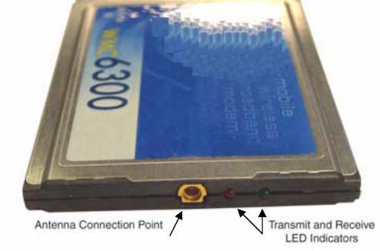
External Connections and LED Indicators
The WMC6300 and the WMC7300 Wireless Modem Card is designed for insertion into an industry-
standard Type II PCMCIA card slot located in a Host device. The Wireless Modem Cards have an
antenna port to connect the external antenna and two LED Indicators. As shown in Figure 1-1 the red
LED is the transmit indicator and the green LED is the receive indicator.
Figure 1-1 WMC showing Antenna Port and LED Indicators
6881011Y52-O August 2005
2-1
Chapter
2
Chapter 2: Software Installation
.............................................
.
.
.
.
This chapter will assist you with the Software installation portion of the process and is further
separated into two main sections: Installing MOTOMESH Client Software on Windows XP and
Installing MOTOMESH Client Software on Windows 2000.
Installing MOTOMESH Client Software on Windows XP
.............................................
.
.
The following procedure outlines the installation of the MOTOMESH client software on a typical
Windows XP platform. Some of the steps may vary slightly based on the configuration of the
individual computers.
If you are running Windows XP Service Pack 2 (SP2), Windows Firewall is
turned on by default. It is recommended that you disable the firewall when
using your Wireless Modem Card.
Procedure 2-1 MOTOMESH Client Software Installation on Windows XP
1 Close and exit any existing MOTOMESH applications running on the computer prior to installation.
2 Insert the Software and Documentation CD into the CD-ROM drive.
3 If the installation program does not start automatically, open the Windows Start menu. Click on Run
then type the following into the dialog box: d:\setupmotomeshclient.exe
where d: specifies the CD-ROM drive and click the OK button.
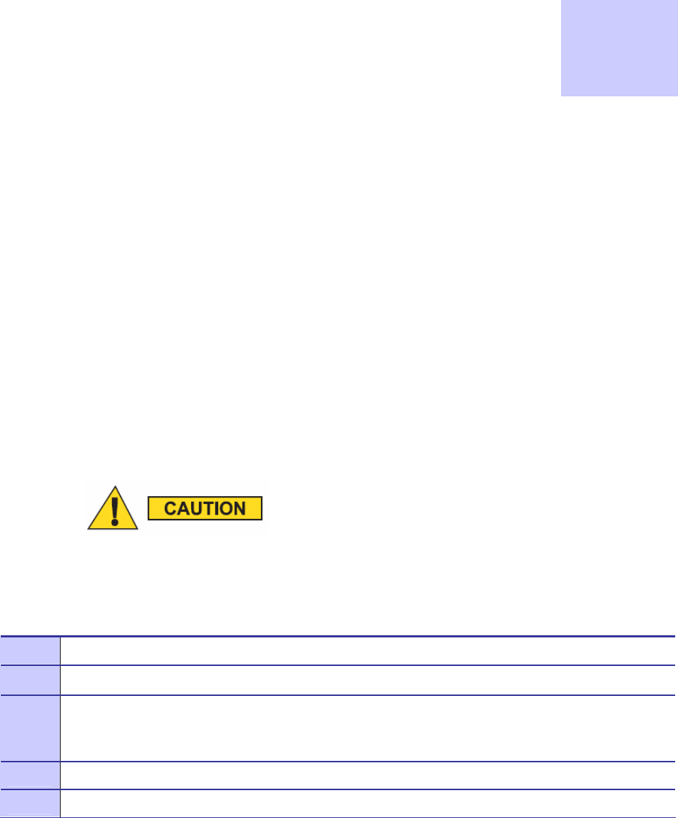
4 Click the Next button to continue the installation process.
5 The MOTOMESH Setup dialog box will be displayed as shown in Figure 2-1.
Chapter 2: Software Installation
6881011Y52-O August 2005
2-2
6 Click the Next button to continue the installation process.
Figure 2-1 MOTOMESH Setup - Welcome Dialog (XP)
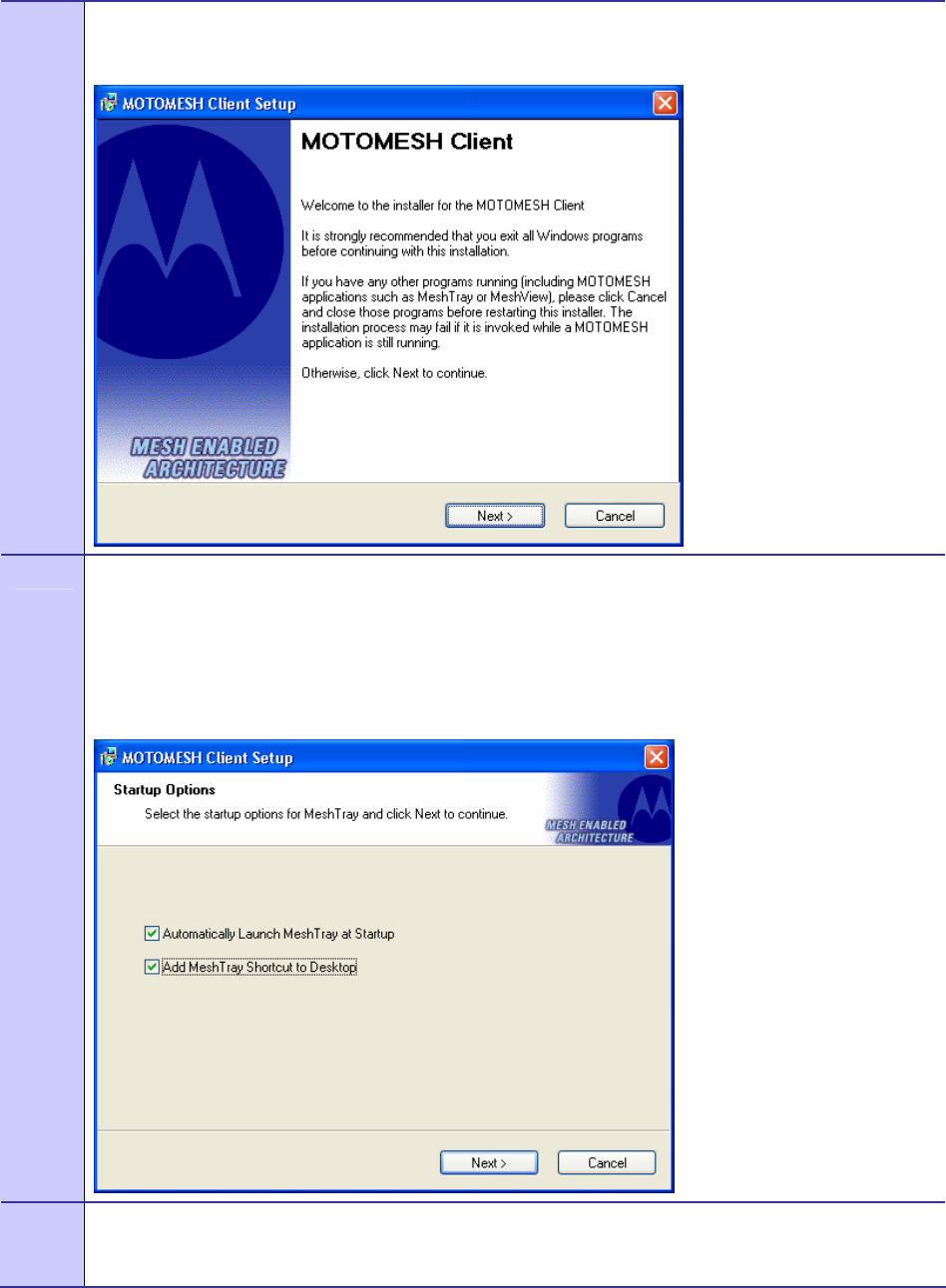
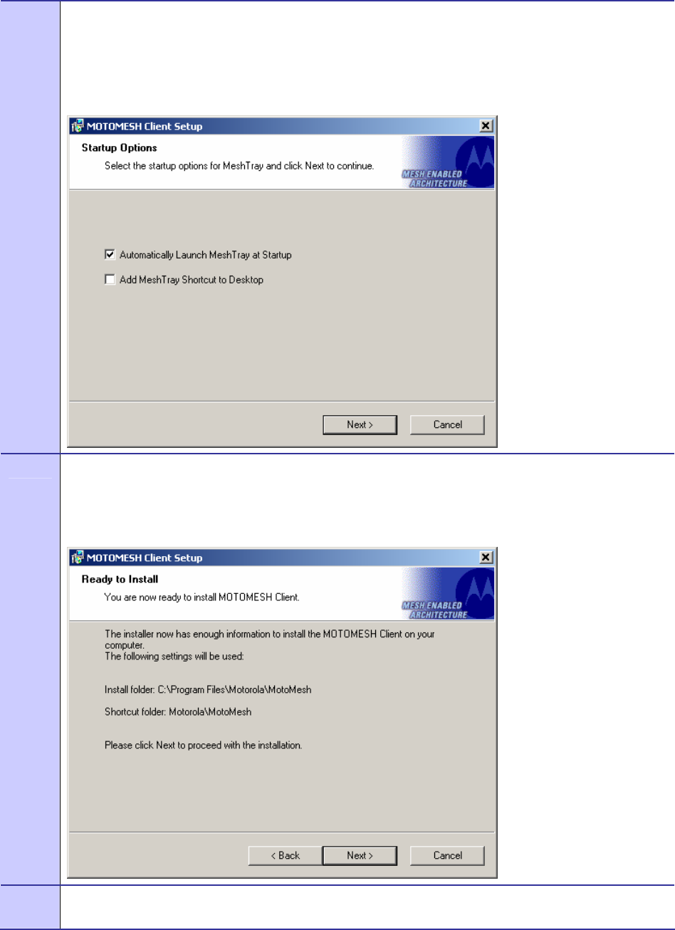
7 In the Startup Options dialog make your selection by checking or un-checking the available options.
Click on the Next button to continue the installation process.
It is recommended that the “Automatically Launch MeshTray at Startup” checkbox is selected; allowing
MeshTray to be available each time the computer is restarted and whenever a Wireless Modem Card
(WMC) is inserted.
Figure 2-2 MOTOMESH Setup – Startup Options (XP)
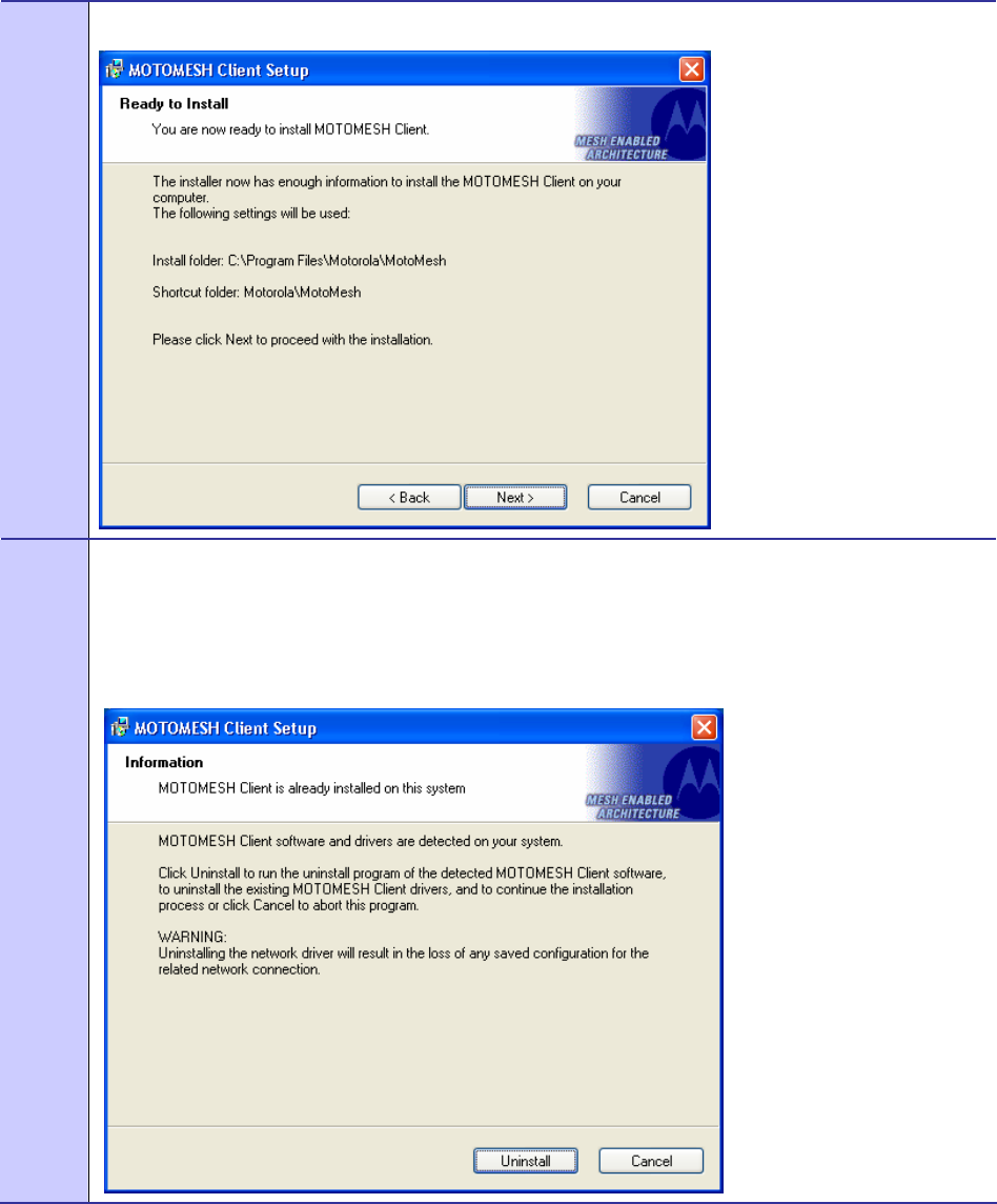
8 The Ready to Install dialog displays the Install Folder location and the Shortcut Folder name that will
be used to install the MOTOMESH software. Click on the Next button to proceed with the installation
process.
MOTOMESH 1.0 Wireless Modem Card Users Guide
6881011Y52-O August 2005
2-3
Figure 2-3 MOTOMESH Setup - Ready to Install (XP)
9 If MOTOMESH has been previously installed on your computer, the Information dialog box will be
displayed as shown in Figure 2-4.
Select the Uninstall button to remove the existing MOTOMESH drivers and continue the installation
process. If you choose not to continue, click the Cancel button.
Figure 2-4 MOTOMESH Setup - Previously Installed Software Detected (XP)
Chapter 2: Software Installation
6881011Y52-O August 2005
2-4
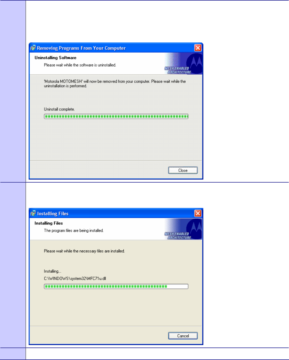
10 If you choose to continue with the installation, the Removing Programs From Your Computer dialog will
be displayed to indicate the progress of the uninstall operation.
When the operation has completed, click on the Close button to dismiss the dialog.
Figure 2-5 MOTOMESH Setup - Uninstalling Software (XP)
11 The Installing Files window will be automatically dismissed as soon as file installation has completed.
Figure 2-6 MOTOMESH Setup - Installing Files Window (XP)
12 The Performing Setup Actions dialog displays a status bar to indicate the progress of the installation.
MOTOMESH 1.0 Wireless Modem Card Users Guide
6881011Y52-O August 2005
2-5
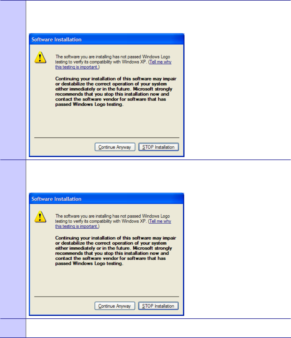
13 A Software Installation dialog indicates that the software is not Windows Logo tested, select the
Continue Anyway button to complete the installation process.
Figure 2-7 Software Installation Dialog Box
14 If a second Software Installation dialog box is displayed as shown in Figure 2-8. Click on the Continue
Anyway button to complete the installation process.
Figure 2-8 Software Installation Dialog Box
15 Select the Continue Anyway button if additional windows display on the screen containing the same
screen contents as in the step above.
Chapter 2: Software Installation
6881011Y52-O August 2005
2-6
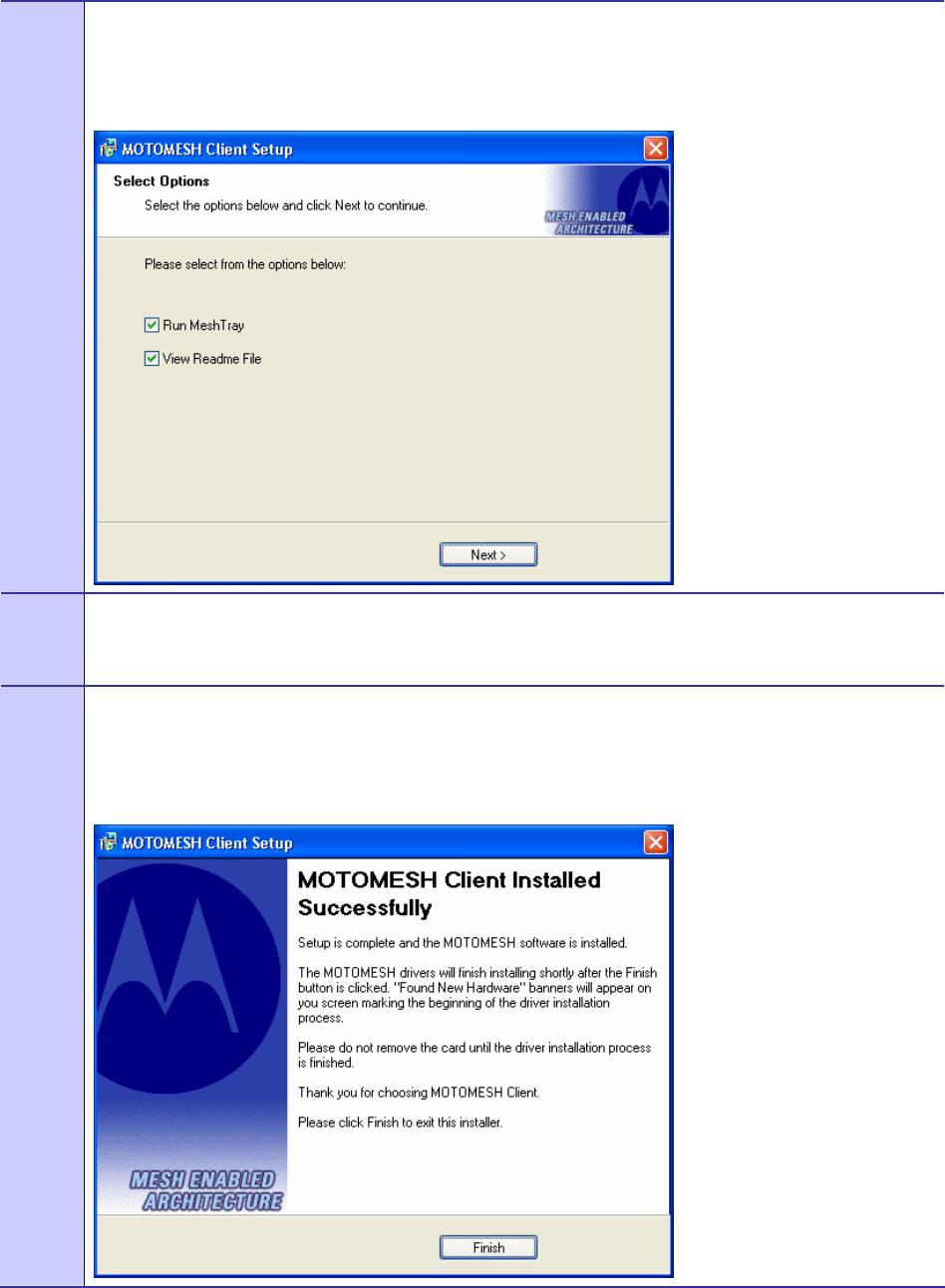
16 The Select Options dialog box will be displayed as shown in Figure 2-9. This installation screen allows
the user to view the ReadMe file during the installation and to run MeshTray immediately following
installation. Click on the Next button to proceed with the installation process.
Figure 2-9 Software Installation Dialog Box
17 If selected, the ReadMe file will be displayed. Review the contents of the file and then dismiss the
dialog box by clicking on the X located in the upper right corner of the dialog.
You MUST close the ReadMe file to complete the installation.
18 From the MOTOMESH Installed Successfully dialog click on the Finish button to exit.
Be sure to close the ReadMe file (if you elected to view it in the earlier steps), otherwise the dialog
shown below will not be displayed.
Figure 2-10 MOTOMESH Setup - MOTOMESH Installed Successfully (XP)
MOTOMESH 1.0 Wireless Modem Card Users Guide
6881011Y52-O August 2005
2-7
Installing MOTOMESH Client Software on Windows
2000
.............................................
.
.
The following procedure outlines the installation of MOTOMESH client software on a typical
Windows 2000 platform. Some of the steps may vary slightly based on the configuration of an
individual computer.
Complete the following procedure to install the MOTOMESH client software:
Procedure 2-2 MOTOMESH Client Software Installation on Windows 2000
1 Close and exit any existing MOTOMESH applications running on the computer prior to installation.
2 Insert the MOTOMESH Software and Documentation CD into the CD-ROM drive. The installation
should begin automatically.
3 If the installation program does not start automatically, select Start | Run then type
d:\setupmotomeshclient.exe (where d: specifies the CD-ROM drive)
Click the OK button.
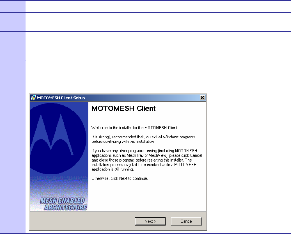
4 The MOTOMESH Setup program will be displayed as shown in Figure 2-11, select the Next button to
continue the installation process.
Figure 2-11 MOTOMESH Setup - Installer Setup Dialog Box (W2K))
Chapter 2: Software Installation
6881011Y52-O August 2005
2-8
5 In the Startup Options dialog make your selection by checking or un-checking the available options.
Click on the Next button to continue the installation process.
It is recommended that the “Automatically Launch MeshTray at Startup” checkbox is selected; allowing
MeshTray to be available each time the computer is restarted.
Figure 2-12 MOTOMESH Setup – Startup Options Dialog Box (W2K)
6 The Ready to Install dialog box will be displayed as shown in Figure 2-13. This dialog box displays the
Install Folder location and the Shortcut Folder name that will be used to install the MOTOMESH
software. Click on Next to proceed with the installation process.
Figure 2-13 MOTOMESH Setup - Ready to Install (W2K)
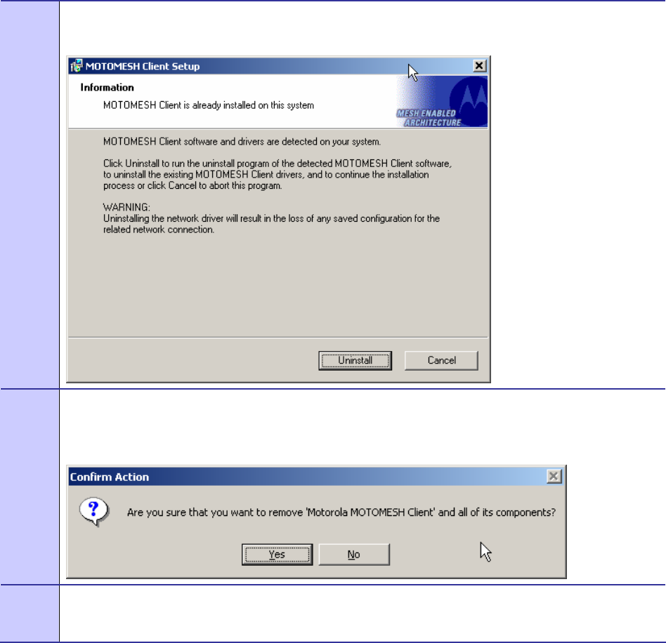
7 If MOTOMESH was previously installed on your computer, the Information dialog box will be
displayed as shown in Figure 2-14.
MOTOMESH 1.0 Wireless Modem Card Users Guide
6881011Y52-O August 2005
2-9
Select the Uninstall button to continue with the removal process or select the Cancel button.
Figure 2-14 MOTOMESH Setup - Software Previously Installed (W2K)
8 From the Confirm Action dialog select the Yes button to remove all of the previously installed
components. If you do not want to continue, click on the No button.
Figure 2-15 Confirm Action – Remove Existing Components
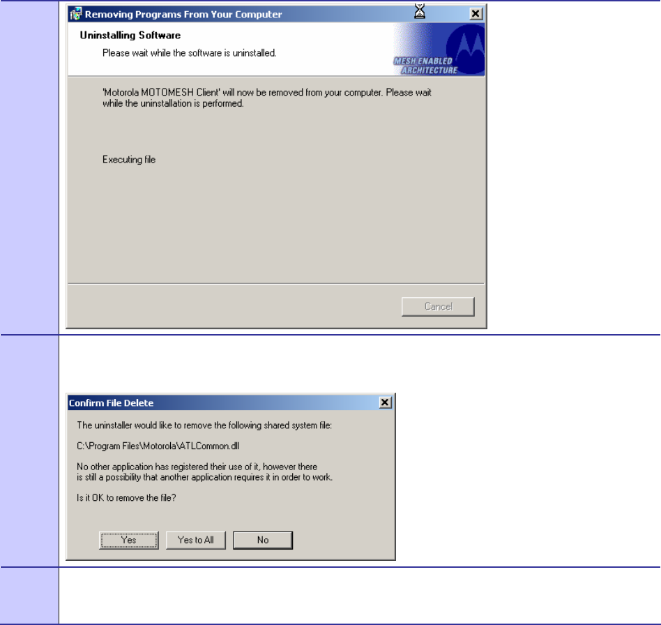
9 The Uninstalling Software dialog will display the un-installation status.
Figure 2-16 Removing Previous Software From Your Computer (W2K)
Chapter 2: Software Installation
6881011Y52-O August 2005
2-10
10 If the Confirm File Delete dialog displays on the screen, select the Yes to All button.
Figure 2-17 Confirm File Deletion (W2K)
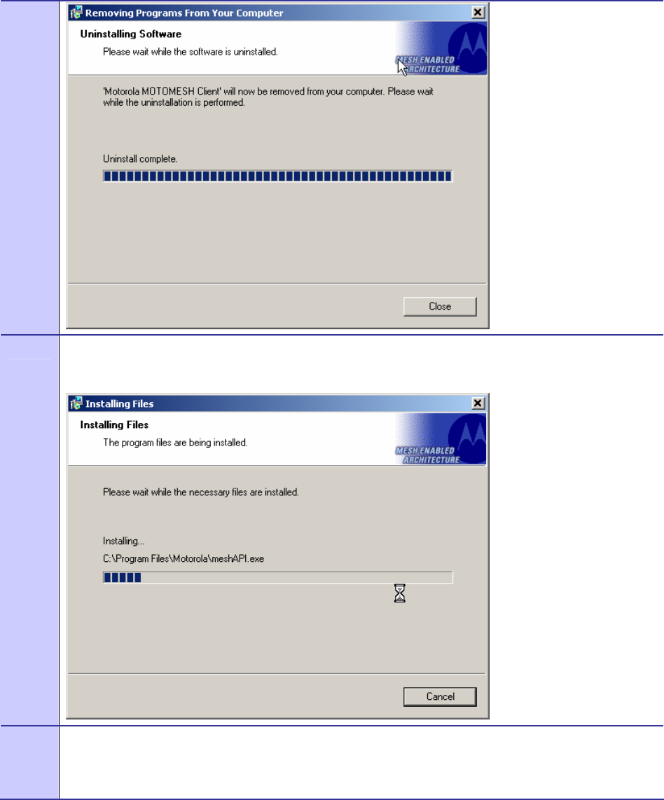
11 The Uninstalling Software dialog will display the deleting file status, select Close when done.
Figure 2-18 Uninstalling Software – Deleting Files (W2K)
MOTOMESH 1.0 Wireless Modem Card Users Guide
6881011Y52-O August 2005
2-11
12 The Installing Files window will be dismissed as soon as the installation of the files is complete.
Figure 2-19 Installing Files Window (W2K)
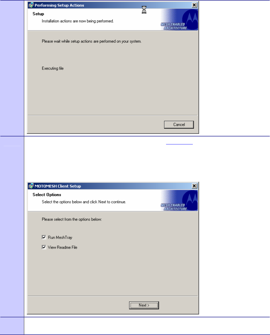
13 During the Setup process, the Performing Setup Actions dialog box displays a status bar that indicates
the progress of the installation.
Figure 2-20 Performing Setup Actions (W2K)
Chapter 2: Software Installation
6881011Y52-O August 2005
2-12
14 The Select Options dialog box will be displayed as shown in Figure 2-21. This installation screen allows
the user to view the ReadMe file during the installation and to run MeshTray immediately following
installation.
Click on the Next button to proceed with the installation process.
Figure 2-21 MOTOMESH Setup - Select Options Dialog Box
15 If selected, the ReadMe file will be displayed. Review the contents of the file and then dismiss the
dialog box by clicking on the X located in the upper-right corner of the dialog box.
MOTOMESH 1.0 Wireless Modem Card Users Guide
6881011Y52-O August 2005
2-13
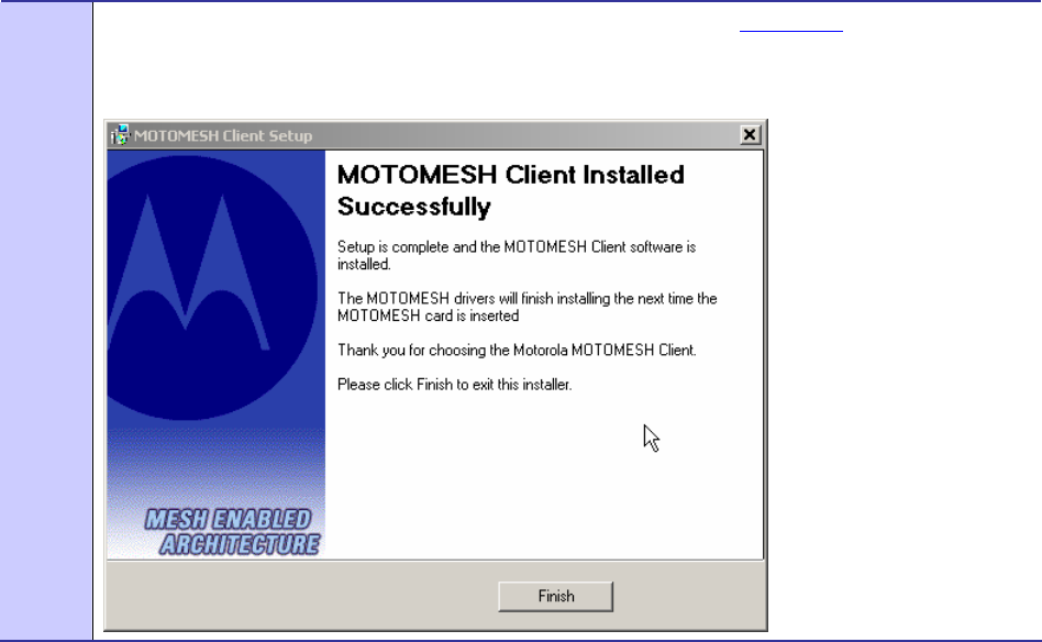
16 The MOTOMESH Installed Successfully dialog will appear as shown in Figure 2-22. Click on the
Finish button to exit.
Figure 2-22 MOTOMESH Installed Successfully (W2K)
Chapter 2: Software Installation
6881011Y52-O August 2005
2-14
This page intentionally left blank.

6881011Y52-O August 2005
3-1
Chapter
3
Chapter 3: Wireless Modem Card
Installation
.............................................
.
.
.
.
This chapter will assist you with the physical installation and configuration of the Wireless Modem
Card.
Prerequisite Installation Information
.............................................
.
.
The previous chapter’s installation instructions must be completed before following the procedures
outlined in this chapter.
Working with the Antenna
.............................................
.
.
The following sections will focus on the proper handling and usage of antennas when using a wireless
modem card.
Connecting the Antenna Assembly
Complete the following procedure to connect the Antenna Assembly (Knuckle or Pigtail type) to the
Wireless Modem Card for use in a standard laptop computer.
Always eject card when not in use.
Procedure 3-1 Connecting the Antenna Assembly
Chapter 3: Wireless Modem Card Installation
6881011Y52-O August 2005
3-2
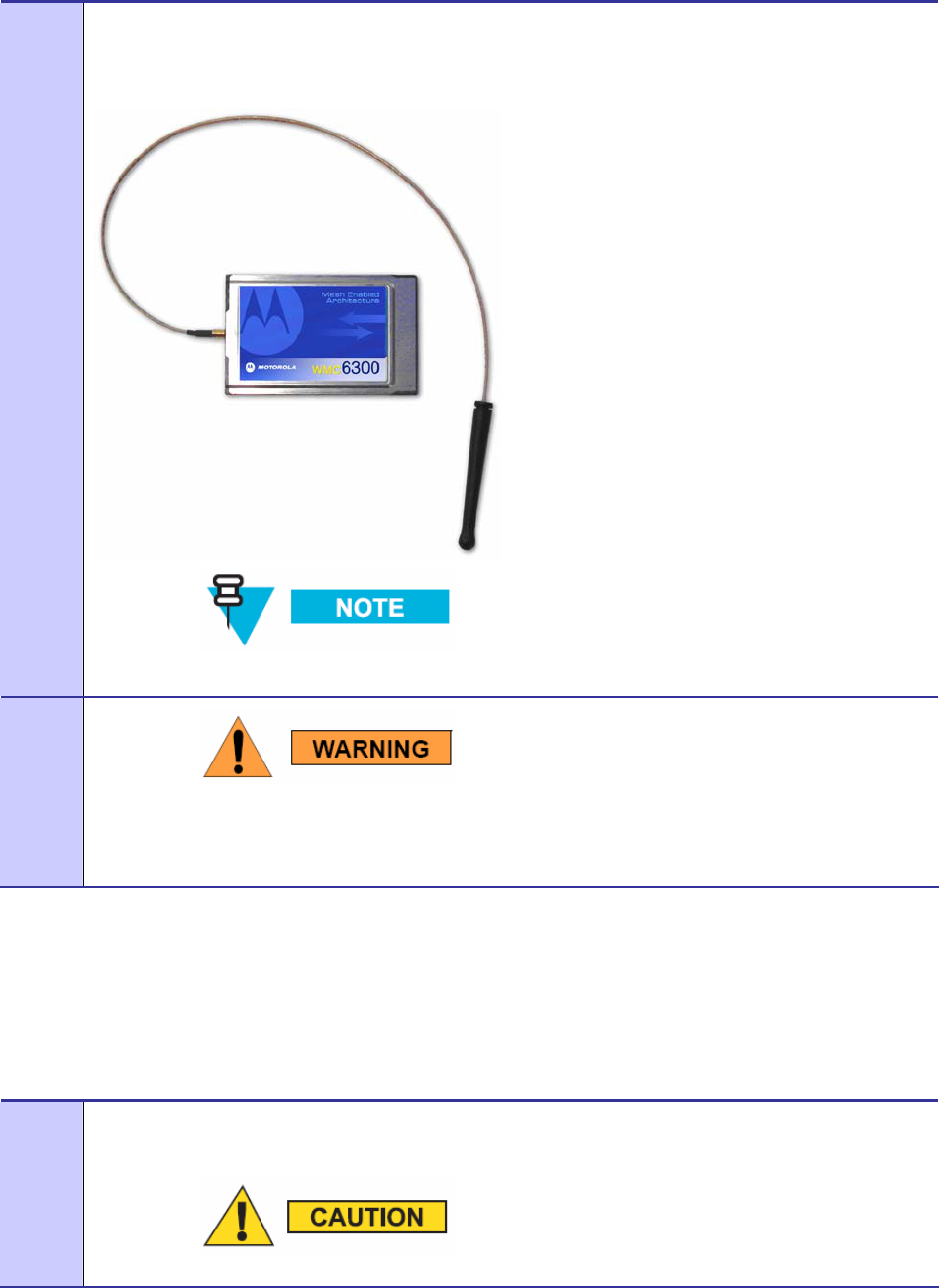
1 Locate the Antenna and insert the connector into the WMC6300 or the WMC7300 antenna port, as
shown in Figure 3-1.
Figure 3-1 Attach the Antenna to the WMC6300 or the WMC7300
The connector will snap into place when fully inserted.
2
Use only FCC approved antennas.
Never use the WMC6300 or the WMC7300 with the Antenna
disconnected from the Card.
Disconnecting a Pigtail Antenna Assembly
Complete care should be taken when disconnecting an antenna from the WMC6300 or the WMC7300
card. Follow the procedure below for correct antenna disconnection instructions:
Procedure 3-2 Disconnecting the Antenna Assembly
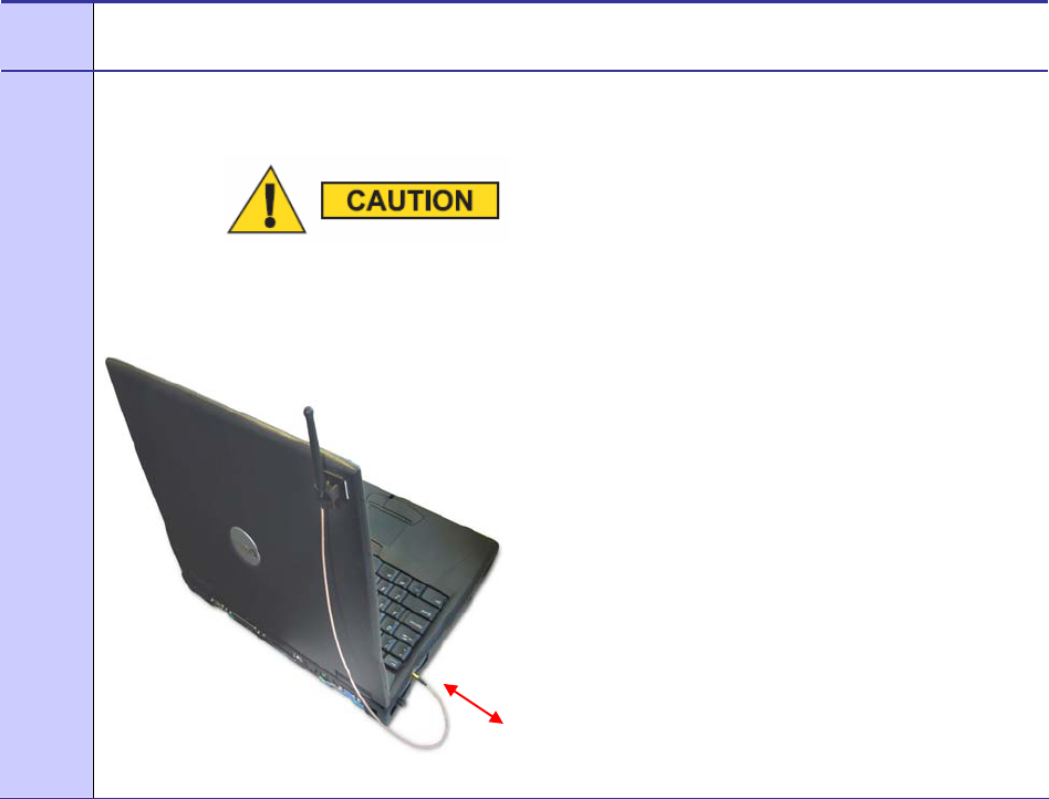
1 When disconnecting a pigtail antenna from the Wireless Modem Card use caution not to damage the
card, connector, or cable.
Applying force in any direction other than parallel to the card may
MOTOMESH 1.0 Wireless Modem Card Users Guide
6881011Y52-O August 2005
3-3
result in excess pressure being applied to the connection between
the WMC connector and the board, which could crack or otherwise
damage a solder joint.
.
2 Pull straight out at the connector to avoid damaging the card, connector or cable.
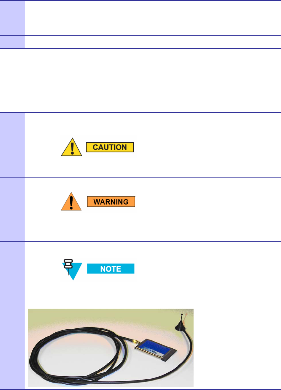
Connecting the Magnetic Antenna Assembly (Optional)
Complete the following procedure to install the Magnetic Mount Antenna on the rooftop of a vehicle.
The length of the Antenna cable is approximately 12 feet.
Procedure 3-3 Installing the Magnetic Mount Antenna Assembly
1 Attach the Magnetic Antenna to the metal rooftop of the vehicle so that the antenna is in a vertical
orientation.
The base of the antenna contains a powerful magnet that secures
the antenna to the rooftop. Use care when attaching the antenna.
2 Route the remaining 12 foot cable as required, to arrive at the Host Computer.
Never use the WMC6300 or the WMC7300 with the Antenna
removed from the rooftop, or with the Antenna disconnected from
the Card.
3 Insert the Antenna Cable Connector into the WMC6300 antenna port as shown in Figure 3-2 .
The connector will snap into place when fully inserted.
Figure 3-2 Attach Magnetic Mount Antenna to the WMC6300
Chapter 3: Wireless Modem Card Installation
6881011Y52-O August 2005
3-4
Handling the WMC6300 and the WMC7300
.............................................
.
.
The following sections will describe the proper installation and removal of the WMC6300 and the
WMC7300 wireless modem cards.
Installing the Wireless Modem Card
Complete the following procedure to install the WMC6300 and the WMC7300 wireless modem cards.
The same installation procedure applies to both wireless modem card model numbers.
Procedure 3-4 Installing the Wireless Modem Card
1 Locate an available Type II PCMCIA card slot in the computer. If necessary, remove the slot dust cover
from the slot.
2 To insure the correct orientation, insert the Wireless Modem Card into the computer’s PCMCIA card
slot with the label side up as shown in Figure 3-3.
Never force the card into the slot.
Figure 3-3 Installing the Wireless Modem Card
Label must
be facing up
MOTOMESH 1.0 Wireless Modem Card Users Guide
6881011Y52-O August 2005
3-5
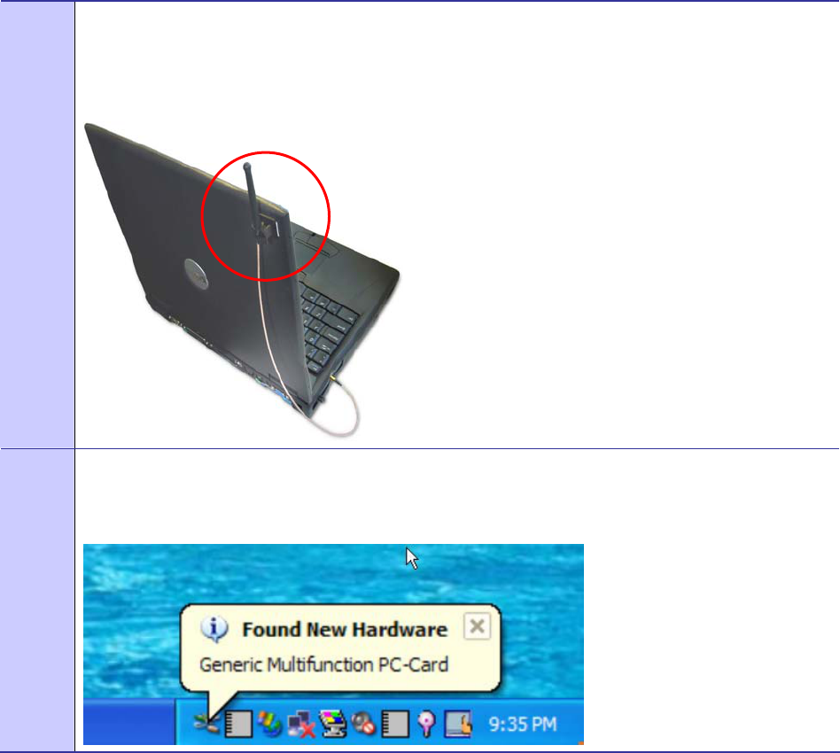
3 The antenna must be attached using the clip and vertically oriented when the laptop is in use as shown in
Figure 3-4.
Figure 3-4 Proper Orientation of Antenna
4 The first time that the card is inserted, a message will be displayed indicating that the PC card has been
found as shown in Figure 3-5
Figure 3-5 Found New Hardware Popup Dialog box
Chapter 3: Wireless Modem Card Installation
6881011Y52-O August 2005
3-6
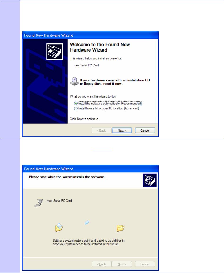
5 The Windows Found New Hardware Wizard for the Serial PC Card will start as shown in Figure 3-6.
Verify that the “Install the software automatically (Recommended)” radio button is selected, and then
click on the Next button.
Figure 3-6 Found New Hardware Wizard – Serial PC Card
6 The Found New Hardware dialog will display the progress information for establishing the restore point
and backing up old files as shown in Figure 3-7.
Figure 3-7 Found New Hardware Wizard - Loading Files
MOTOMESH 1.0 Wireless Modem Card Users Guide
6881011Y52-O August 2005
3-7
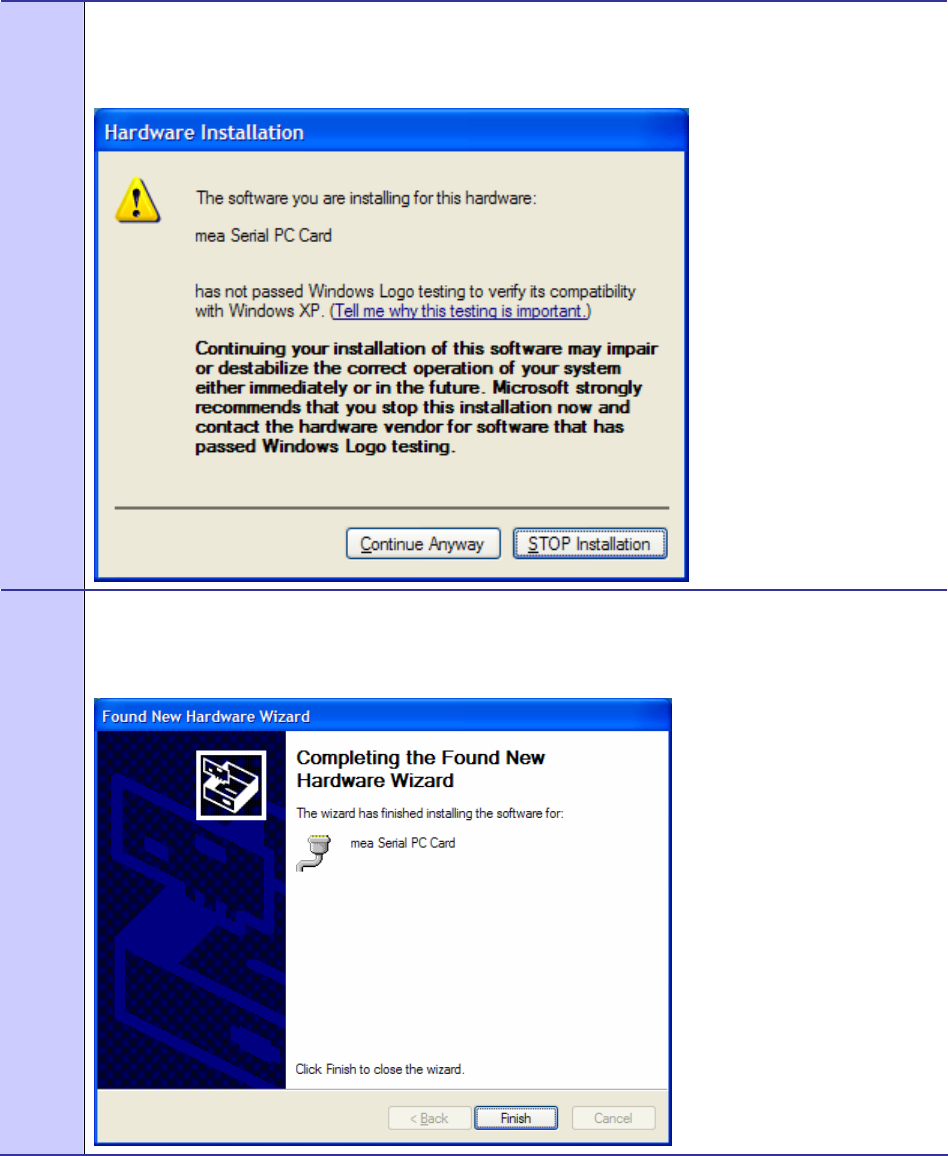
7 As soon as the above step is complete, the Hardware Installation dialog box shown in Figure 3-8 will be
displayed. Click on the Continue Anyway button in the Hardware Installation dialog box.
Figure 3-8 Hardware Installation Dialog Box
8 The Found New Hardware Wizard Complete dialog box will appear as shown in Figure 3-9. Click on
the Finish button.
Figure 3-9 Found New Hardware Wizard – Complete
Chapter 3: Wireless Modem Card Installation
6881011Y52-O August 2005
3-8
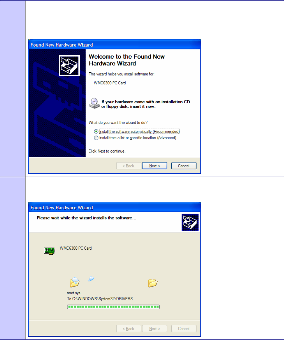
9 An additional Found New Hardware Wizard will be displayed as shown in Figure 3-10. Verify that the
Install the software automatically (Recommended) radio button is selected, and then click on the Next
button.
Figure 3-10 Found New Hardware Wizard
10 A Loading Files dialog box will appear as shown in Figure 3-11. Go on to the next step.
Figure 3-11 Found New Hardware Wizard Loading Files
MOTOMESH 1.0 Wireless Modem Card Users Guide
6881011Y52-O August 2005
3-9
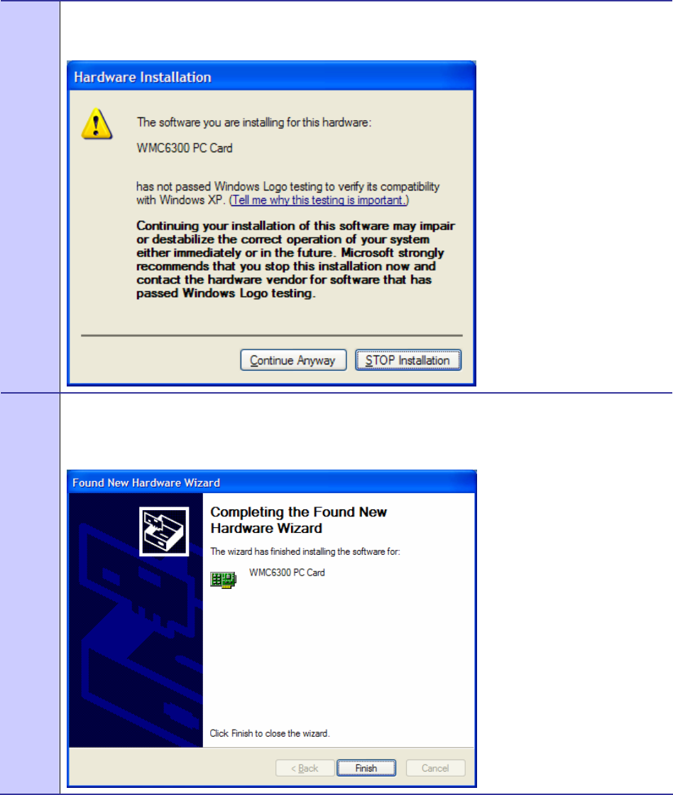
11 From the Hardware Installation dialog box, Figure 3-12, click on the Continue Anyway button.
Figure 3-12 Hardware Installation Dialog Box - WMC6300 PC Card
12 The Found New Hardware Wizard Complete dialog box will be displayed as shown in Figure 3-13.
Click on the Finish button.
Figure 3-13 Found New Hardware Wizard Complete
Chapter 3: Wireless Modem Card Installation
6881011Y52-O August 2005
3-10
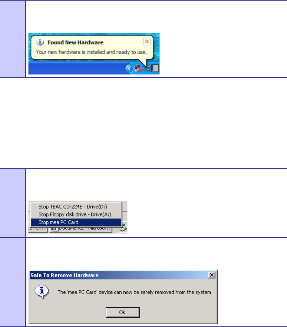
13 The Found New Hardware pop-up window will appear confirming that the driver installation is
complete and the hardware is ready to use.
Figure 3-14 Found New Hardware - Wizard Complete
Removing the Wireless Modem Card
This section details specific Wireless Modem Card removal instruction to ensure that power to the card
is disabled prior to removal.
Complete the following procedure prior to ejecting the Wireless Modem Card from the computer.
Procedure 3-5 Removing the Wireless Modem Card
1 Click on the Unplug or Eject Hardware icon in the system task bar. Select “Safely remove Generic
Multifunction PC-Card” from the popup menu as shown in Figure 3-15.
Figure 3-15 Unplug or Eject Hardware Icon
2 Wait for a message that indicates that the device may be safely removed from the system as shown in
Figure 3-16.
Figure 3-16 Safe to Remove Hardware - WMC6300 Card

MOTOMESH 1.0 Wireless Modem Card Users Guide
6881011Y52-O August 2005
3-11
3 Eject the WMC6300 from the PCMCIA slot as shown in Figure 3-17.
Figure 3-17 Removing the WMC6300 from the PCMCIA slot

6881011Y52-O August 2005
4-1
Chapter
4
Chapter 4: MeshTray
.............................................
.
.
.
.
MeshTray™ is a status and configuration application that reports vital and statistical information about
the Wireless Modem Card (WMC). Because MeshTray is a “tray” application, it stays in the desktop
system status tray when it is minimized.
In this chapter you will learn about the available MeshTray features, the different ways to start
MeshTray, and how to remove the application from your computer.
MeshTray System Tray Icon Status
.............................................
.
.
The MeshTray icon resides in the System Tray and indicates the current mode of operation as well as
the state of the wireless interface.
There are two main modes of operation: Infrastructure or Peer-to-Peer. In infrastructure mode the
device is able to associate with an IAP, while in peer-to-peer mode, IAP association is not possible
(intentionally or unintentionally), and a wireless mesh network is automatically accessed with the use
of any available peer devices instead.
The table below describes all the possible states that the MeshTray icon will exhibit in the Windows
system tray.
Table 4-1 MeshTray Icon States
Icon State Explanation
Peer to Peer with Neighbors
The icon indicates that the device is running in peer-to-peer mode;
the MeshTray icon displays the Link Quality to the associated IAP
as color-coded bars. The greater the number of bars, the better the
Link Quality.
Peer to Peer without Neighbors
The icon indicates that the IP address has not yet been acquired
from the DHCP server. When this happens, the IP field in the
Status Tab displays a flashing “X” or “0” IP.
Inactive or Disconnected
The inactive state applies when a WMC is not inserted. The
disconnected state applies if a card is inserted but is not yet
associated with an IAP.

Chapter 4: MeshTray
6881011Y52-O August 2005
4-2
Starting MeshTray
During the software installation process, you can choose to run MeshTray immediately upon
completion of the installation process.
Procedure 4-1 Starting MeshTray
1 To start the MeshTray application, double-click on the MeshTray icon located on the desktop.
The icon will be available on the desktop only if the election to place it on the desktop has been selected
at the time of MeshTray installation.
2 As an alternative to the above step, you can also:
Click on Start | Programs | Motorola | MotoMesh | MeshTray.exe.
3 As an alternative to the previous steps, you can also:
Click on the MeshTray icon in the Windows System Tray to restore the application to a property sheet
(tab-style) interface as shown in Figure 4-1
MeshTray Tab Contents
.............................................
.
.
The following sections will describe the contents of all the available tabs within the MeshTray
application, and their respective functionality.
Excellent IAP Association
(Infrastructure mode)
When the WMC is associated with an IAP (not peer-to-peer), the
MeshTray icon displays the Link Quality to the associated IAP as
color-coded bars. The greater the number of bars, the better the
Link Quality.
Very Good IAP Association
Same explanation as listed for the Excellent IAP icon, except that
the IAP link quality is measured to be Very Good.
Medium IAP Association
Same explanation as listed for the Excellent IAP icon, except that
the IAP link quality is measured to be Medium.
Poor IAP Association
Same explanation as listed for the Excellent IAP icon, except that
the IAP link quality is measured to be Poor
Very Poor IAP Association
Same explanation as listed for the Excellent IAP icon, except that
the IAP link quality is measured to be Very Poor.
6881011Y52-O August 2005
4-1
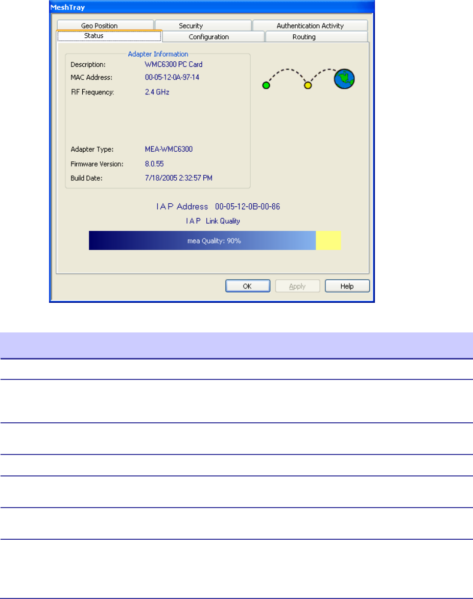
Status Tab
Figure 4-1 MeshTray Status Tab
Table 4-2 Status Tab - Adapter Information Section
Status Tab Item Explanation
Description Indicates the device type and model number.
MAC Address Displays the MAC Address assigned to the
Wireless Modem Card on the current computer
being viewed through MeshTray.
RF Frequency Displays either 2.4 or 4.9 GHz RF operating
frequency.
Adapter Type Describes the type of adapter.
Firmware Version Current version of the firmware version
running on the device.
Build Date Current Build Date of the firmware version
running on the device.
IAP Address The IAP Address of the Access Point linked to
by the device.
If the device is operating in Peer-to-Peer mode,
the IP address will be shown as all zeros.
Chapter 4: MeshTray
6881011Y52-O August 2005
4-2
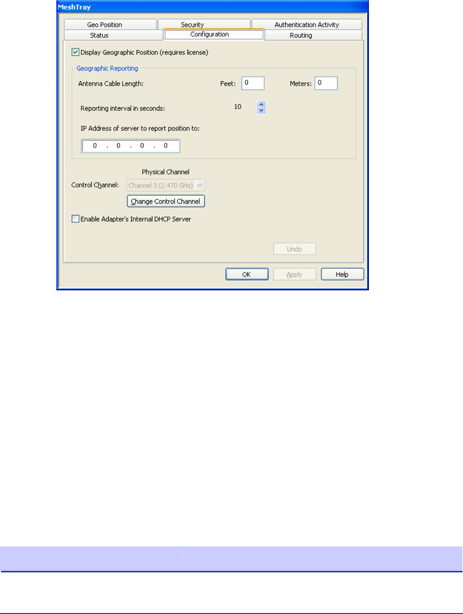
Configuration Tab
The contents of the MeshTray Configuration tab are described in the following sections and tables.
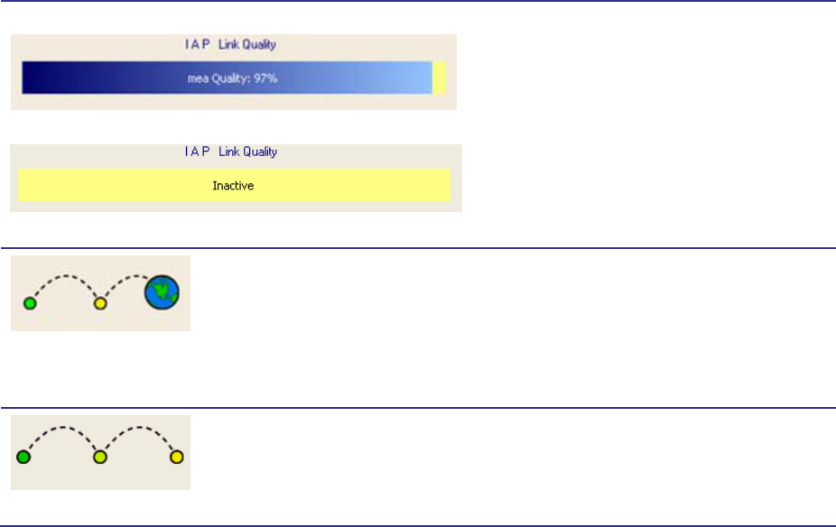
IAP Link Quality
Infrastructure Mode (%)
Peer-to-Peer Mode (IAP link inactive)
The Access Point link quality is represented as
a percentage bar. A link quality of 100% is
considered Excellent. It is also an indication
that the device is running in Infrastructure
mode as opposed to Peer-to-Peer.
A device that is running in Peer-to-Peer mode
will display a yellow percentage bar along with
the word “inactive”.
Operating Mode Graphic - Infrastructure
The two modes that a MOTOMESH or a MEA
wireless device operates in is: Infrastructure or
Peer-to-Peer. Within the MeshTray Status tab,
the graphic mode automatically adjusts to the
operating mode. The Infrastructure mode is
intuitively represented by two hops and a globe
connected with a dotted links.
Operating Mode Graphic - Peer-to-Peer
The Peer-to-Peer mode is represented by three
hops connected with dotted links. See
explanation for the previous mode graphic for
more details.
MOTOMESH 1.0 Wireless Modem Card Users Guide
6881011Y52-O August 2005
4-3
Figure 4-2 MeshTray Configuration Tab
Geographic Position
The Display Geographic Position option is selectable and the user may configure the reporting
interval as shown in Figure 4-2, if the license for this licensed feature has been purchased and enabled
on the network. Another indicator that this feature is enabled is that the Geo Position tab is viewable;
otherwise the Geo Position tab would not be shown. For additional information about the Geo Position
tab and its use, please see the Geo Position tab section of this documentation.
If the Display Geographic Position checkbox is grayed out, and a license has been purchased, check
with your company’s Network Administrator about enabling this option from within the MOTOMESH
MeshManager application.
Geographic Reporting
The Geographic Reporting feature becomes enabled when the Geographic Position checkbox is both
enabled (licensed, not grayed out) and contains a check mark.
Table 4-3 Geographic Reporting section
Section Item Explanation
Antenna Cable Length
To ensure a detailed Geographic Positioning calculation, the length
of the antenna needs to be entered in feet or meters. Only whole
numbers can be used in these entry fields.

Chapter 4: MeshTray
6881011Y52-O August 2005
4-4
Control Channel Configuration
There are four channels available for 2.4 GHz network communications. The Network Administrator
can map the four available Physical channels to three Data channels and one Control channel. The
Data channels will be used for data transmission between subscriber devices, infrastructure devices,
and the network. When the using the 2.4 GHz Wireless Modem Card (WMC), the Control channel is
designated for internal MEA communication. By default, it is set to the physical channel 3 (2.47 GHz).
When working with the 4.9 GHz WMC the available channels are 4.950, 4.955, 4.960, and 4.965.
Changing the Control Channel
A user should never change the channel mappings unless specifically instructed to do so by the
Network Administrator.
Do not enter decimal point values as
they will be dropped after, the “Apply”
button is selected.
Reporting Interval in seconds
The reporting interval must be entered in seconds (up to a
maximum of 180 seconds) and is used for updating the Geo
Position tab data contents for longitude and latitude or X, Y, Z
positions for the Spherical Coordinate Use the Up arrow to set the
number of seconds.
IP Address of server to report
position to
This is the IP Address where the geo position is forwarded or
reported to. Typically, this is a centralized server that displays the
position of all devices on the network.
MOTOMESH 1.0 Wireless Modem Card Users Guide
6881011Y52-O August 2005
4-5
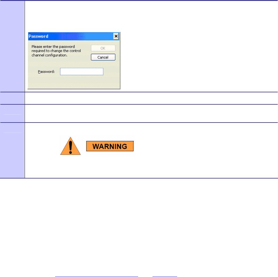
Procedure 4-1 Changing the Control Channel
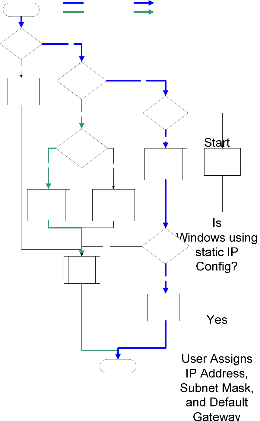
Enabling the WMCs Internal DHCP Server Feature
If a DHCP server is not available on your network, you may choose to either provide a viable static IP
address in Windows or select the Enable Adapter’s DHCP Server checkbox. The two scenarios lead
to several TCP/IP setting considerations which will be explored in the following sections, please see
the figure below for a visual explanation.
When the Enable Adapter’s DHCP Server checkbox is selected, an IP address will be provided to
Windows by the adapter’s internal DHCP server. A unique IP address will be created from the device’s
MAC address and a subnet mask will be available. To complete the configuration, the default
gateway, and the DNS settings need to be provided in the TCPIP Properties window, as specified in
the section Setting a User Supplied IP Address. See Figure 4-4 for a visual explanation of the
available configurations.
1 Click on the Change Control Channel button located on the Configuration tab, if you are required to
change the control channel at the request of a Network Administrator. A Password window will display.
Figure 4-3 Password Protection Panel
2 Enter the password provided by your network administrator and then select the OK button.
3 Click on the newly enabled Control Channel dropdown arrow and then select the Control Channel
specified by your Network Administrator.
4 Select the Apply button located on the Configuration tab to finalize your selection.
Any unauthorized change can cause the WMC6300 to stop
communication with the network and other subscriber devices.
Chapter 4: MeshTray
6881011Y52-O August 2005
4-6
Figure 4-4 MeshTray and Windows TCPIP, DHCP, and DNS Setting Options
MOTOMESH 1.0 Wireless Modem Card Users Guide
6881011Y52-O August 2005
4-7
Setting a User Supplied IP Address
To setup a User Supplied IP address, first obtain a valid IP address from your Network Administrator.
This is the IP address to be entered in the IP Address box on the Internet Protocol (TCP/IP) Properties
dialog’s General tab.
Procedure 4-2 Setting a User Supplied Address
1 From the Start menu, select Settings
Æ
Control Panel. Double click on the Network and Dial-up
Connections icon.
Figure 4-5 Control Panel – Network and Internet Connections Icon
2 The Network and Internet Connections window will be displayed. Double-click on Network and
Internet Connections then right-click on the Local Area Connection icon and select Properties.
Figure 4-6 Network and Dial-up Connections Window
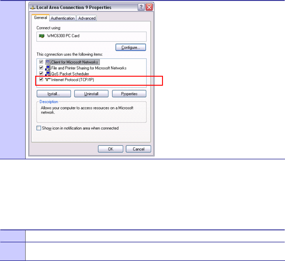
3 On the Local Area Connection Properties dialog, select Internet Protocol (TCP/IP), and then click on
the Properties button.
Figure 4-7 Local Area Connection Properties Dialog Box
Chapter 4: MeshTray
6881011Y52-O August 2005
4-8
Configuring the DNS Address
.............................................
.
.
Manual DNC configuration is only necessary when a DHCP server does not exist on the Network.
Procedure 4-3 Configuring the DNS Address
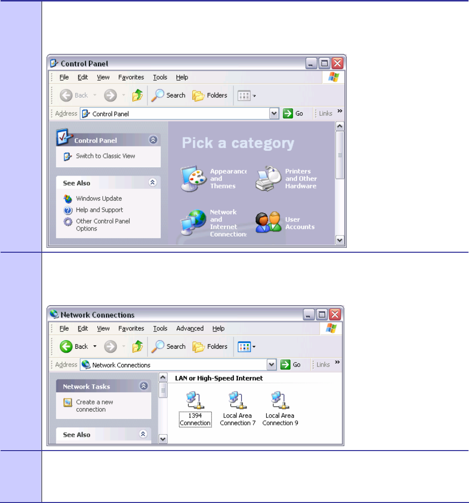
1 Select Start | Control Panel to display the Windows Control Panel.
2 On the Control Panel, double-click on the Network and Internet Connections icon, and then double-click
on the Network Connections icon.
MOTOMESH 1.0 Wireless Modem Card Users Guide
6881011Y52-O August 2005
4-9
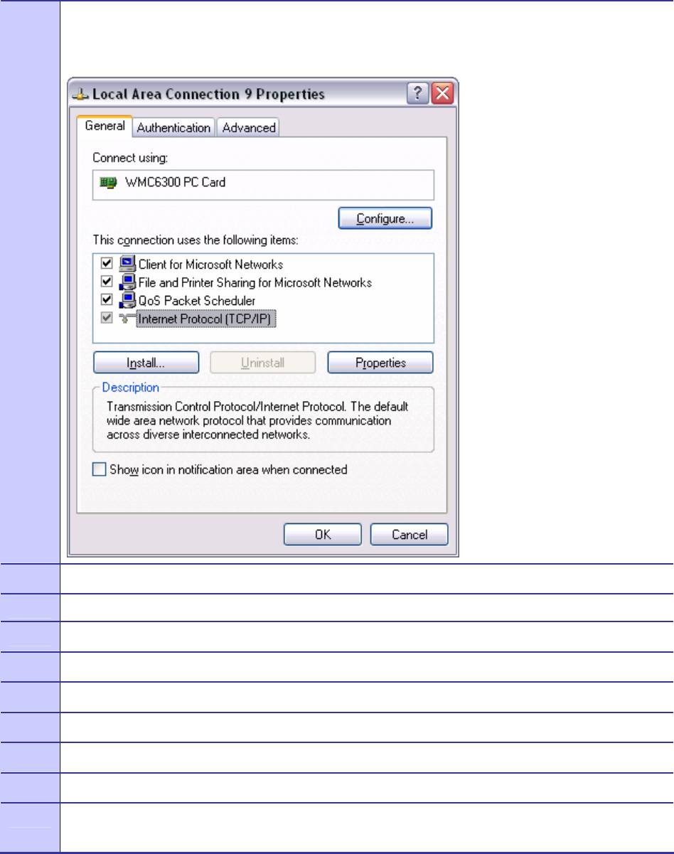
3 Right-click on the Local Area Connection corresponding to the Wireless Modem Card and select the
Properties button.
Figure 4-8 Local Area Connection Properties Dialog Box
4 Highlight Internet Protocol (TCP/IP) in the Components dialog box as shown in Figure 4-8.
5 Click on the Properties button.
6 Click on the Advanced button.
7 Click on the DNS tab
8 Click on the DNS Add button.
9 Enter the DNS Server IP Address provided by the Network Administrator and then click the Add button.
10 Click on the OK button to close the Advanced TCP/IP Settings dialog box.
11 Click on the OK button to close the Internet Protocol (TCP/IP) Properties dialog box.
12 Click on the OK button to close the Local Area Connection Properties dialog box.
This configuration should remain in the Windows XP host.
Geo Position Tab
Chapter 4: MeshTray
6881011Y52-O August 2005
4-10
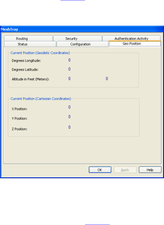
If your Wireless Modem Card has been licensed for Geo-Location, an optional Geo Position tab will
be displayed as shown in Figure 4-8. For the parameters to be enabled (not grayed-out), the Display
Geographic Position checkbox needs to be selected in the Configuration tab.
Figure 4-9 MeshTray Geo Position Tab
MeshTray Routing Tab
If your Wireless Modem Card has been licensed to display routing information, an optional tab will be
displayed in MeshTray as shown in Figure 4-9.
MOTOMESH 1.0 Wireless Modem Card Users Guide
6881011Y52-O August 2005
4-11
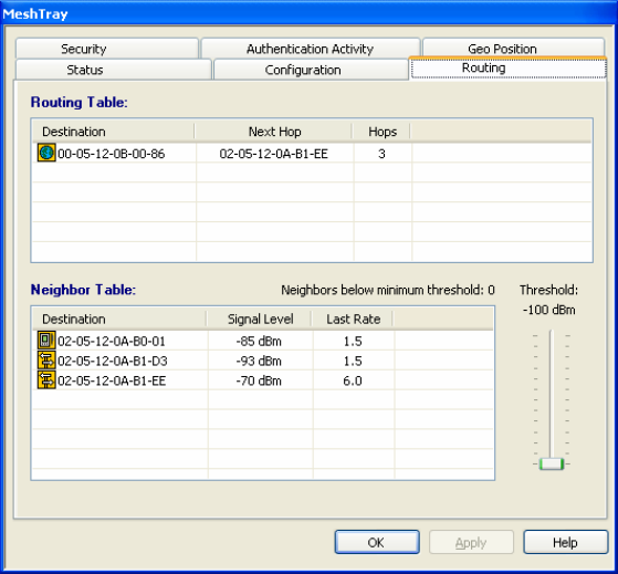
Figure 4-10 MeshTray Routing Tab
Routing Table
The Routing Table displays the MAC address for the Destination node and the node to be utilized for
the Next Hop, the number of Hops to the Destination node.
Neighbor Table
The Neighbor Table displays the MAC address and the Signal Level for the adjacent nodes that the
WMC may route through, depending on the desired end node.
The Last Rate column displays the last data rate used to transmit user data to the neighbor destination.
Threshold
Adjusting the threshold control allows the user to view neighbors that have a signal level greater than
or equal to the selected threshold level.

Chapter 4: MeshTray
6881011Y52-O August 2005
4-12
Routing Icons
Table 4-4 Routing Tab Icons
Icon Description
Unknown
Indicates a device type not known to MeshTray.
Subscriber Device (SD)
The Computer icon represents a Subscriber Device using a MEA Wireless
Modem Card in the network.
Wireless Router
The Arrow icon represents a Wireless Router (WR), or Mesh Wireless
Router (MWR) in the MEA network. The WR is an infrastructure device
dedicated to routing data.
IAP
The Globe icon represents an Intelligent Access Point (IAP) in the MEA
network. A MEA Intelligent Access Point is an infrastructure device that
allows access to the wired network.
MOTOMESH 1.0 Wireless Modem Card Users Guide
6881011Y52-O August 2005
4-13
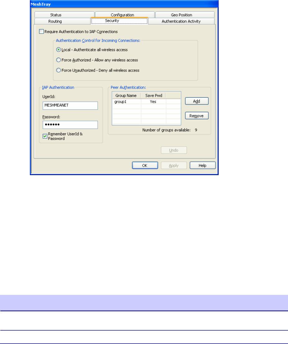
MeshTray Security Tab
The Security tab is used to set the IAP and Peer Authentication passwords to gain access to the
network.
Figure 4-11 MeshTray Security Tab
f
Require Authentication to IAP Connections
When the Require Authentication to IAP Connections checkbox option is unchecked, it allows
authentication of any device currently being monitored and authentication of devices added to the
network configuration as they are discovered. Alternately, when the checkbox is selected,
authentication to the IAP becomes a requirement.
Authentication Control for Incoming Connections
When in peer-to-peer mode, select one of the radio buttons to select the desired authentication option.
Table 4-5 Authentication Control Icons
Icon Description
Local – Authenticate all wireless access Authentication is based on Peer information. (See
the Peer Authentication section in this chapter).
Force Authorized – Allow any wireless access Allow all clients.
Chapter 4: MeshTray
6881011Y52-O August 2005
4-14
IAP Authentication
To gain access to the IAP, the user must enter a UserId and Password recognized by that IAP.
Note: This is only true when IAP is not set to Force Authorized.
Table 4-6 IAP Authentication Dialog
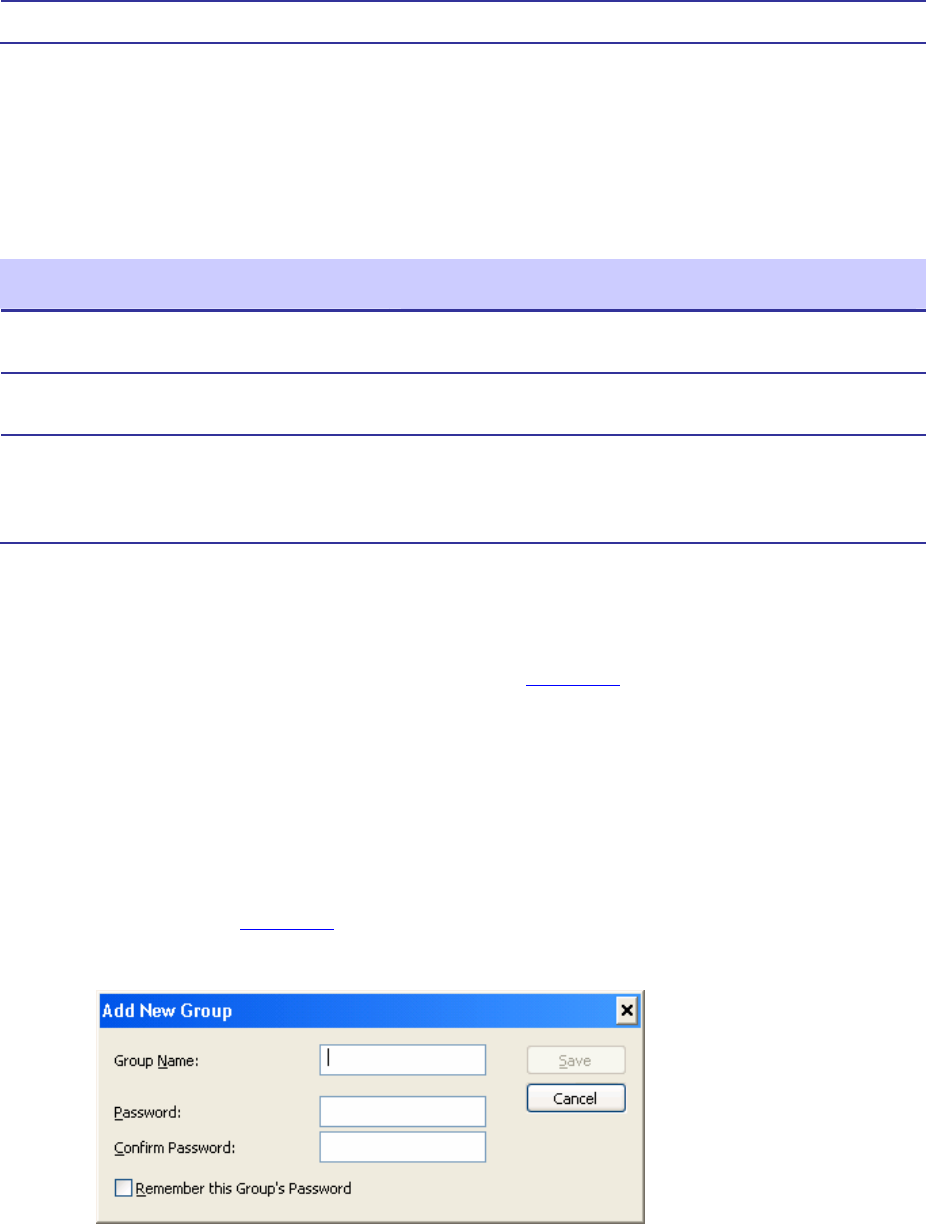
Peer Authentication
The Peer Authentication pane displays a table containing the Group Name and Save Pwd stats for all
users within a Peer Authorization group, as shown in Figure 4-10.
In a Peer-to-Peer network, the user can specify a group name and password to gain access to all other
devices associated as peers. The same group name and password must be specified on each node
included in the group.
Clicking the Add button launches the Add New Group window for the user to add the Group Name and
Password. The Remember this Name and Password checkbox provides the option to save the Group
Name and Password settings.
Click on the Remove button, located on the Security tab, to remove all group names highlighted in the
table as shown in Figure 4-10.
Figure 4-12 Peer Authentication – Add New Group
Force Unauthorized – Deny all wireless access Deny all clients.
Parameter Description
User ID Will be used for authentication and authorization for network
access.
Password Will be used for authentication and authorization for network
access.
Remember User ID and Password Allows the encrypted form of the UserId and Password to be
written to the registry for future reference. Selecting this option
creates a potential weakness in network security since it will
allow anyone who has access to the Windows user account
MOTOMESH 1.0 Wireless Modem Card Users Guide
6881011Y52-O August 2005
4-15
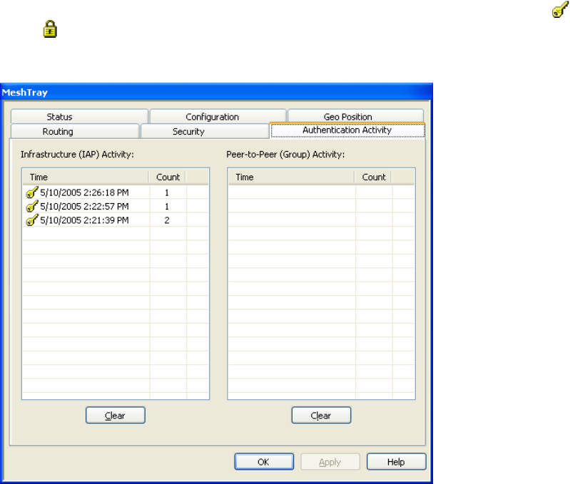
MeshTray Authentication Activity Tab
The Authentication Activity tab displays Infrastructure (IAP) Activity and Peer-to-Peer (Group)
Activity with an associated Time stamp and Count for the number of attempted authentications. The
icons displayed in the Time column identify whether attempted authentications were successful ( ) or
failed ( ).
Figure 4-13 MeshTray Authentication Activity Tab
Chapter 4: MeshTray
6881011Y52-O August 2005
4-16
This page intentionally left blank.

6881011Y52-O August 2005
5-1
Chapter
5
Chapter 5: Customer Information
.............................................
.
.
.
.
This chapter lists the relevant FCC Certification and Product Safety Information for the MOTOMESH
devices described in this manual.
Customer Service Information
.............................................
.
.
If you have read this document and made every effort to resolve installation or operation issues
yourself and still require help, please contact Motorola System Support Center (SSC) using the
following contact information:
Hours of Operation
7 days a week, 24 hours
Technical Support: 800-221-7144 (USA)
Obtaining Support
Motorola provides technical support services for your system and recommends that you coordinate
warranty and repair activities through the Motorola System Support Center (SSC). When you consult
the Motorola SSC, you increase the likelihood that problems are rectified in a timely fashion and that
warranty requirements are satisfied. Check your contract for specific warranty and service information.
System Information
To be provided with the best possible opportunity for support, collect the following system information
and have it available when obtaining support.
• Location of the system
• Date the system was put into service
• Software or firmware version information for components of your system
Chapter 5: Customer Information
6881011Y52-O August 2005
5-2
• Serial number(s) of the device(s) or component(s) requiring support
• A written description of the symptom or observation of the problem:
- When did it first appear?
- Can it be reproduced?
- What is the step-by-step procedure to cause it?
• Do other circumstances contribute to the problem? For example, changes in weather or
other conditions?
• Maintenance action preceding problem:
- Upgrade of software or equipment
- Change in the hardware or software configuration
- Software reload - from backup or from CD-ROM (note the version and date)
Return Material Request
After collecting system information, contact the Motorola System Support Center for assistance or to
obtain a Return Material Authorization (RMA) number for faulty Field Replaceable Entities (FREs):
North America: 800-221-7144
Radio Products and Services Division
The Radio Products and Services Division is your source for manuals and replacement parts.
Radio Products and Services Division Telephone Numbers
The telephone numbers for ordering are: (800)-422-4210 (US and Canada orders)
The Fax numbers are: (800)-622–6210 (US and Canada orders)
The number for help identifying an item or part number is (800)-422-4210; select choice “3” from the
menu
Returning System Components to Motorola
Motorola's service philosophy is based on field replaceable entities (FREs). FREs are system
components identified by Motorola to be returned to Motorola for repair. In turn, Motorola sends you a
replacement FRE component to help you maintain maximum operating performance for your system.
Returning FREs
Return faulty FREs to Motorola for repair. When you return an assembly for service, follow these best
practices:
• Place any assembly containing CMOS devices in a static-proof bag or container for
shipment.
MOTOMESH 1.0 Wireless Modem Card Users Guide
6881011Y52-O August 2005
5-3
• Obtain a return authorization (RA) number from the Motorola System Support Center.
• Include the warranty, model, kit numbers, and serial numbers on the job ticket, as
necessary.
• If the warranty is out of date, you must have a purchase order.
• Print the return address clearly, in block letters.
• Provide a phone number where your repair technician can be reached.
• Include the contact person's name for return.
• Pack the assembly tightly and securely, preferably in its original shipping container.
Chapter 5: Customer Information
6881011Y52-O August 2005
5-4
This page intentionally left blank.

6881011Y52-O August 2005
6-1
Chapter
6
Chapter 6: Certification and Safety
Information
.............................................
.
.
.
.
This chapter lists the relevant FCC Certification and Product Safety Information for the MOTOMESH
devices described in this manual.
FCC Regulatory Information
.............................................
.
.
FCC Information
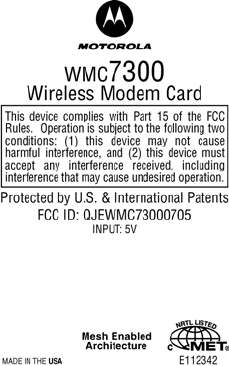
This device complies with Part 15 of the FCC Rules. Operation is subject to the following two
conditions: (1) this device may not cause harmful interference, and (2) this device must accept any
interference received; including interference that may cause undesired operation.
Federal Communications Commission (FCC) Statement:
This equipment has been tested and found to comply with the limits for a Class B digital device,
pursuant to part 15 of the FCC Rules. These limits are designed to provide reasonable protection
against harmful interference in a residential installation. This equipment generates, uses, and can
radiate radio frequency energy and, if not installed and used in accordance with the instructions, may
cause harmful interference to radio communications. However, there is no guarantee that interference
will not occur in a particular installation. If this equipment does cause harmful interference to radio or
television reception, which can be determined by turning the equipment off and on, the user is
encouraged to try to correct the interference by one or more of the following measures:
• Reorient or relocate the receiving antenna.
• Increase the separation between the equipment and receiver.
• Connect the equipment into an outlet on a circuit different from that to which the
receiver is connected.
• Consult the dealer or an experienced radio/TV technician for help
Chapter 6: Certification and Safety Information
6881011Y52-O August 2005
6-2
FCC RF Radiation Exposure Statement
This equipment complies with FCC radiation exposure limits set forth for an uncontrolled
environment. This equipment should be installed and operated with minimum distance 20 cm between
the radiator and your body.
Safety Information for the MEA WMC7300
The Federal Communications Commission (FCC) with its action in ET Docket 96-8 has adopted a
safety standard for human exposure to radio frequency (RF) electromagnetic energy emitted by FCC
certified equipment. MOTOROLA products meet the uncontrolled environmental limits found in
OET-65 and ANSI C95.1, 1991. Proper operation of this radio according to the instructions found in
this manual and the hardware and software guides on the MOTOMESH CD will result in user
exposure that is substantially below the FCC recommended limits.
• Do not touch or move the antenna(s) while the unit is transmitting or receiving.
• Do not hold any component containing a radio such that the antenna is very close to or
touching any exposed parts of the body, especially the face or eyes, while transmitting.
• Do not operate a portable transmitter near unshielded blasting caps or in an explosive
environment unless it is a type especially qualified for such use.
• Do not operate the radio or attempt to transmit data unless the antenna is connected;
otherwise, the radio may be damaged.
Use the antenna supplied by Motorola.
Use of other antennas is prohibited and may violate FCC regulations.
The manufacturer is not responsible for any unauthorized modifications to this
equipment. Unauthorized modifications could void user’s authority to operate
device.

MOTOMESH 1.0 Wireless Modem Card Users Guide
6881011Y52-O August 2005
6-3
FCC RF Radiation Exposure Statement
This equipment complies with FCC radiation exposure limits set forth for an uncontrolled
environment. This equipment should be installed and operated with a minimum distance of 2 meters
between the radiator and your body.
Safety Information for the MOTOMESH Products
The Federal Communications Commission (FCC) with its action in ET Docket 96-8 has adopted a
safety standard for human exposure to radio frequency (RF) electromagnetic energy emitted by FCC
certified equipment. Motorola MOTOMESH products meet the uncontrolled environmental limits
found in OET-65 and ANSI C95.1, 1991. Proper operation of this radio according to the instructions
found in this manual and the hardware and software guides on the MOTOMESH CD will result in user
exposure that is substantially below the FCC recommended limits.
• Do not touch or move the antenna(s) while the unit is transmitting or receiving.
• Do not hold any component containing a radio such that the antenna is very close to or
touching any exposed parts of the body, especially the face or eyes, while transmitting.
• Do not operate a portable transmitter near unshielded blasting caps or in an explosive
environment unless it is a type especially qualified for such use.
• Do not operate the radio or attempt to transmit data unless the antenna is connected;
otherwise, the radio may be damaged.
Safety Certification
Conforms to UL STD ANSI/UL 60950 3rd Edition
Certified to CAN/CSA C22.2 NO. 60950-00
Equipment shall be suitable for use in Air pressure: 86kPa to106kPa.
Chapter 6: Certification and Safety Information
6881011Y52-O August 2005
6-4
WMC7300 Product Label Example
MOTOMESH 1.0 Wireless Modem Card Users Guide
6881011Y52-O August 2005
6-5

6881011Y52-O August 2005
Index-1
Index
Index
.............................................
.
.
.
.
A
Add New Group, 4-14
Antenna Assembly, 3-1
antenna port, 3-2
Antenna Port, 1-2
Automatically Launch, 2-2
C
Control Channel, 4-4, 4-5
Copyrights, iii
Customer Service Information, 5-1
D
DHCP, 4-1, 4-5, 4-6
Disclaimer, iii
DNS, 4-5, 4-6, 4-8, 4-9
E
Excellent, 4-2
F
Found New Hardware Wizard, 3-6
G
Geo Position Tab, 4-9
Geo-Location, 4-10
I
IAP Authentication, 4-14
Infrastructure, 4-1, 4-2, 4-15
Infrastructure mode, 4-2
Install Folder, 2-2
IP Address of server to report, 4-4
L
LED Indicators, 1-2
Link Quality, 4-1, 4-2
M
Magnetic Antenna, 3-3
Magnetic Mount Antenna, 3-3
MeshTray.exe, 4-2
Multifunction PC-Card, 3-10
N
Neighbor Table, 4-11
Neighbors, 4-1
P
PCMCIA card slot, 3-4
Peer Authentication, 4-14
Peer to Peer, 4-1
Peer-to-Peer, 4-1, 4-2, 4-14, 4-15
Pigtail type, 3-1
R
ReadMe, 2-6, 2-12
Require Authentication to IAP, 4-13
Routing Icons, 4-12
Routing Table, 4-11
run MeshTray immediately, 2-12
S
Security Tab, 4-13
Serial PC Card, 3-6
Startup, 2-2
T
Table 3, 4-1
TCP/IP, 4-5, 4-7, 4-9
Threshold, 4-11
Trademarks, iii
U
Uninstall, 2-3
User Supplied IP Address, 4-7
W
Windows Logo tested, 2-5
Index
6881011Y52-O August 2005
Index-2
This page intentionally left blank.

Glossary
6881011Y52-O August 2005
Glossary-1
Glossary
Glossary
.............................................
.
.
.
IAP – Intelligent Access Point
MEA – Mesh Enabled Architecture
MiSC – Mobile Internet Switching Controller
MWR – Mesh Wireless Router
SBC – Single Board Computer
SD – Subscriber Device, a general description to a device type that is usually a WMC or
a VMM.
VMM– Vehicle Mounted Modem
WMC – Wireless Modem Card, can apply to any model number
WR – Wireless Router same as MWR
Glossary
6881011Y52-O August 2005
Glossary-2
This page intentionally left blank.