Zebra Technologies WND-2100-00AA WhereWand II Adapter User Manual
Zebra Technologies Corporation WhereWand II Adapter Users Manual
UserManual.wiki
>
Zebra Technologies
>
WND 2100 00AA User Manual
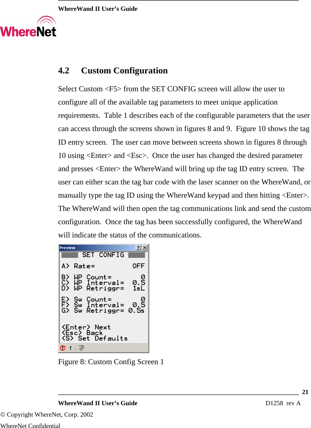
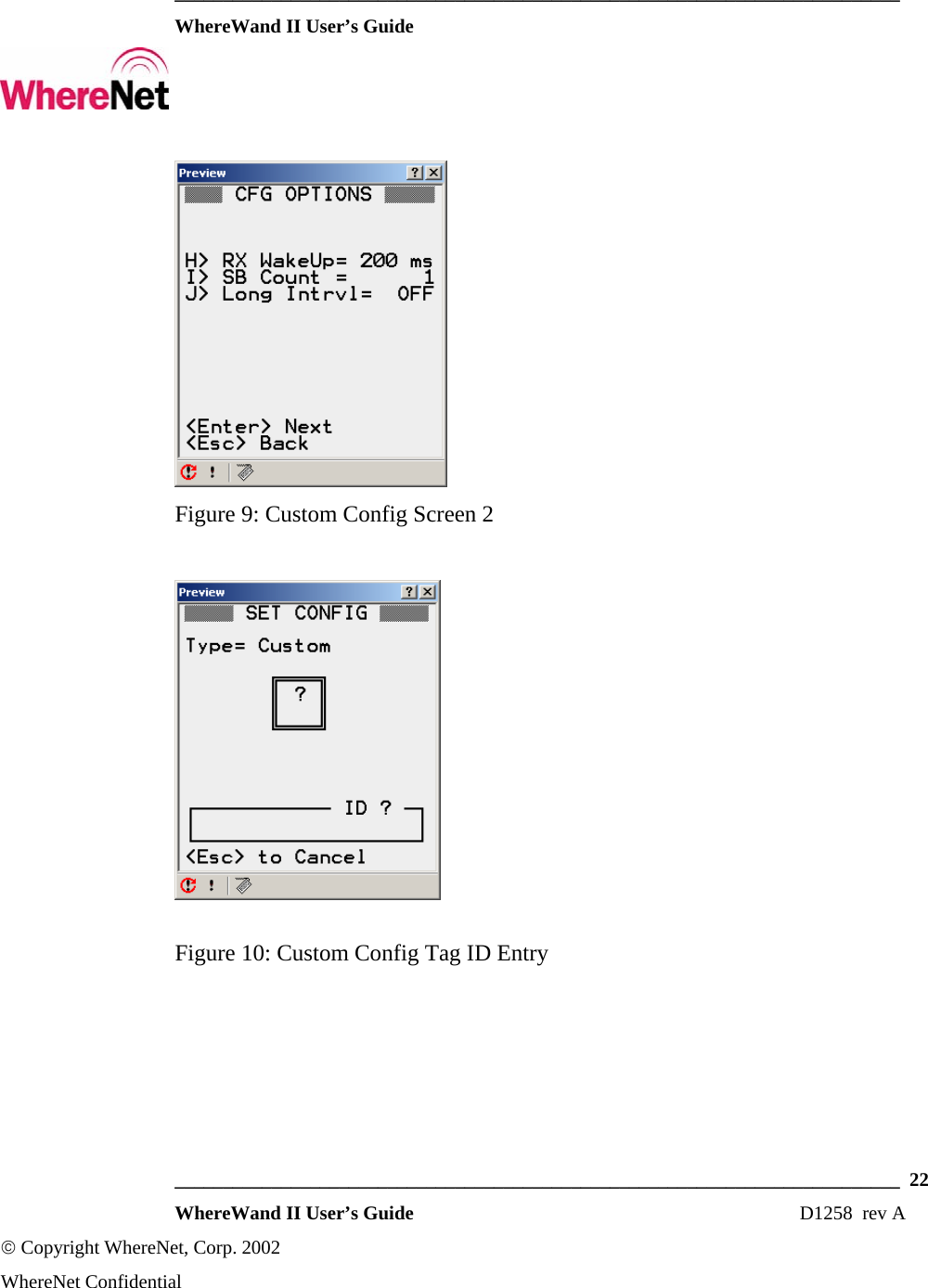
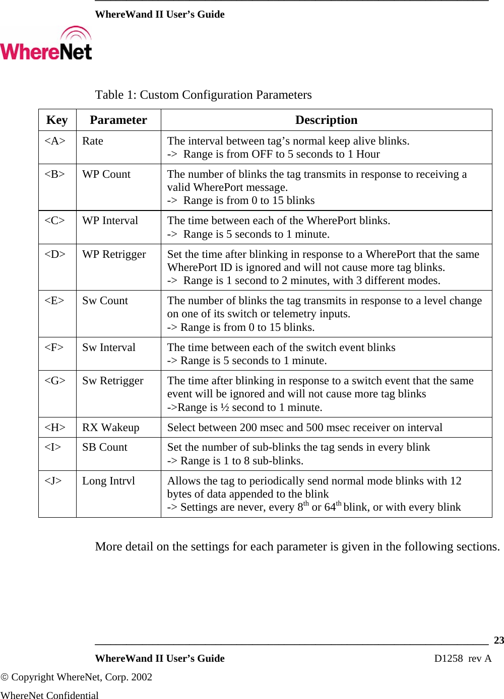
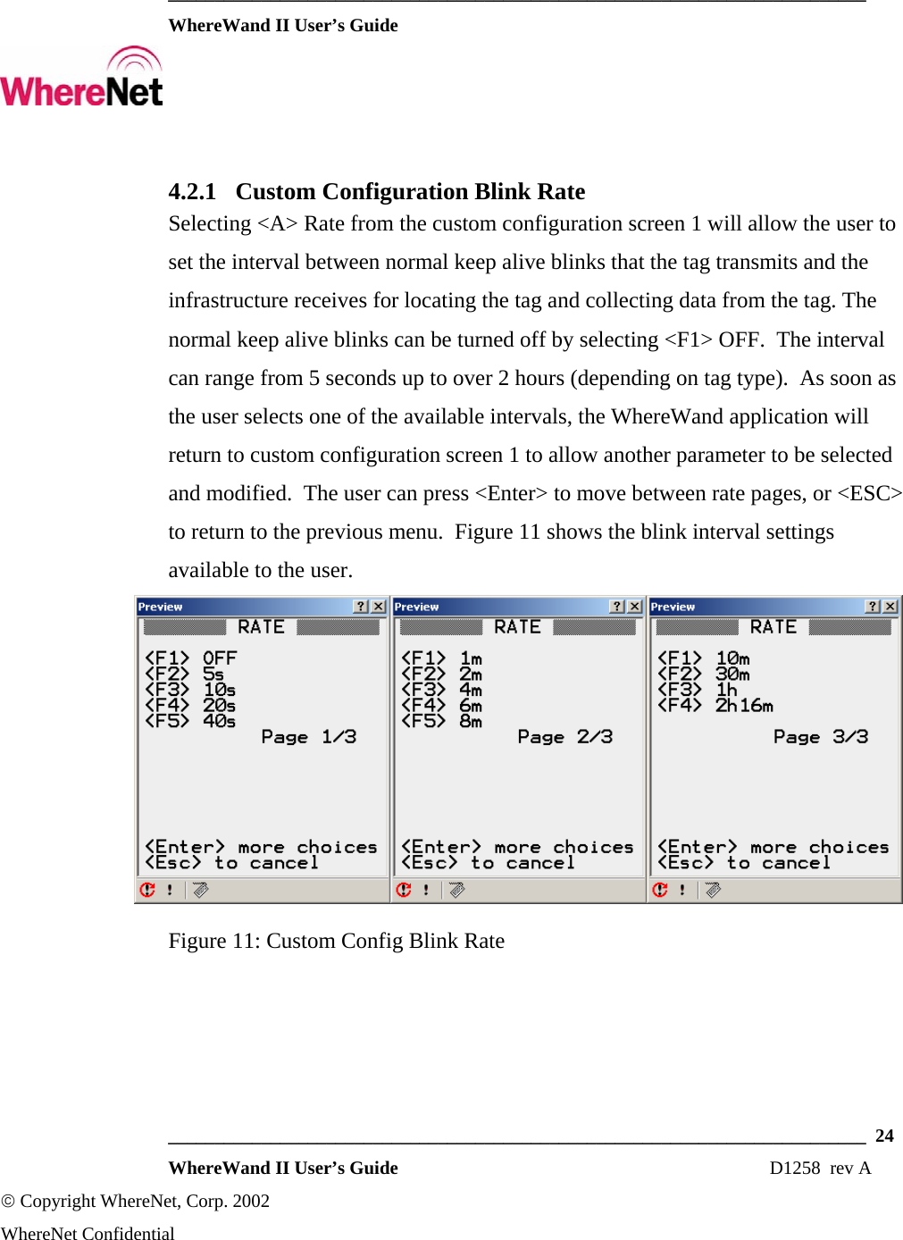
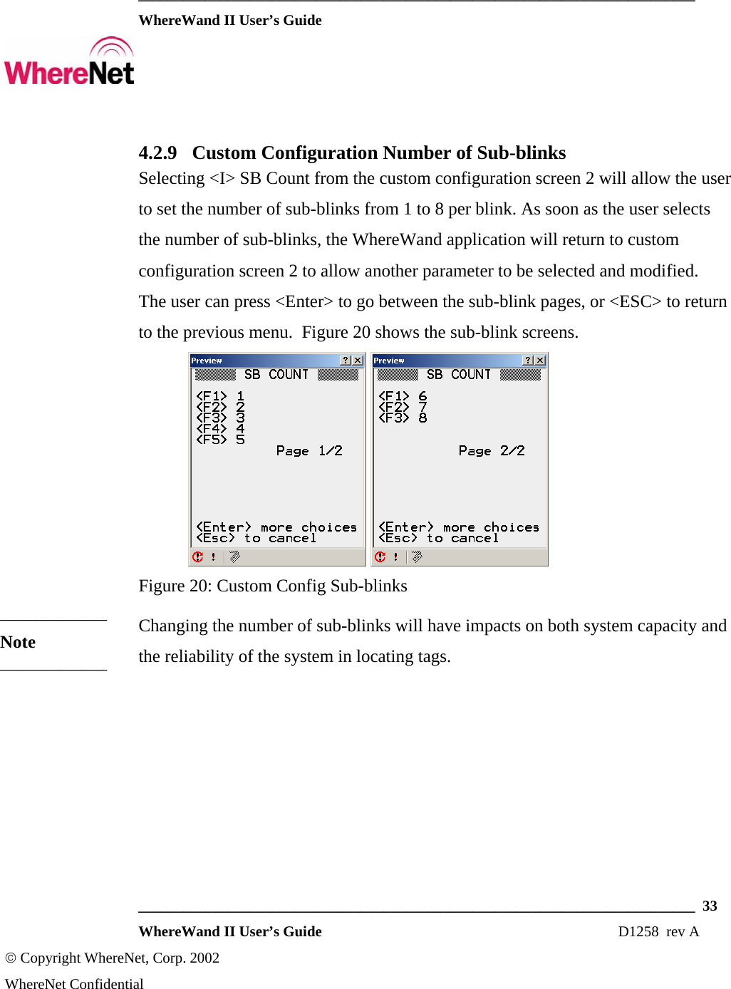
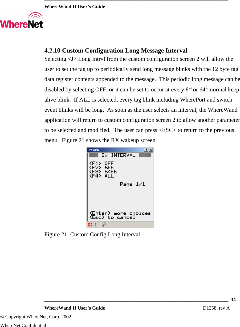
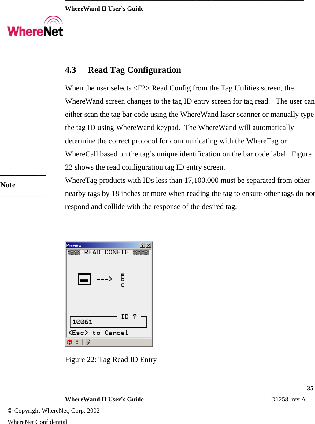
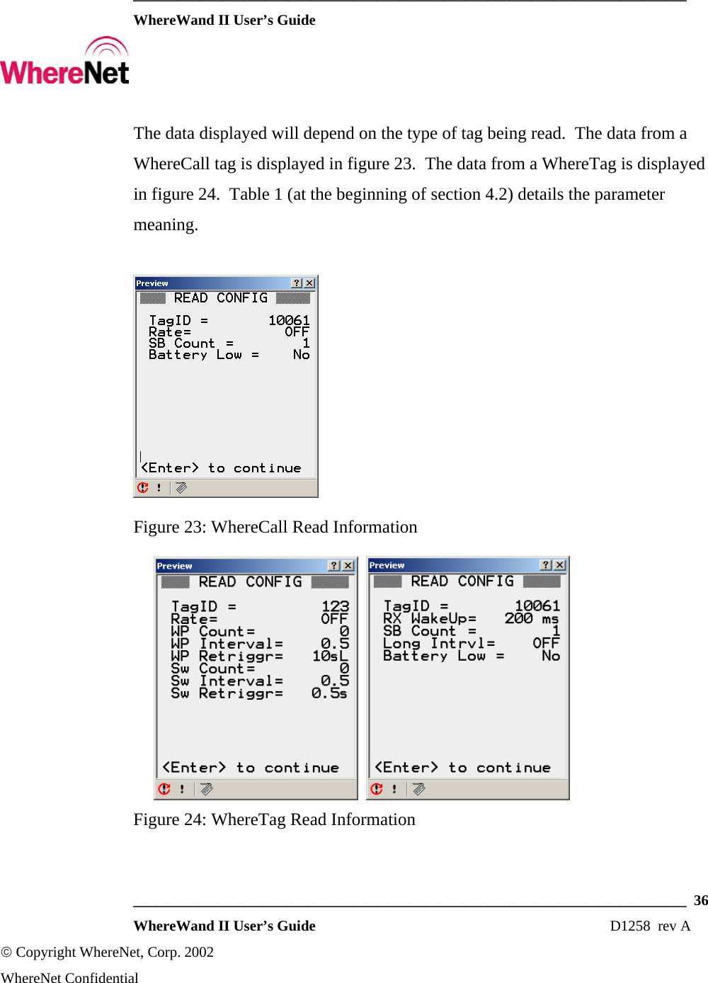
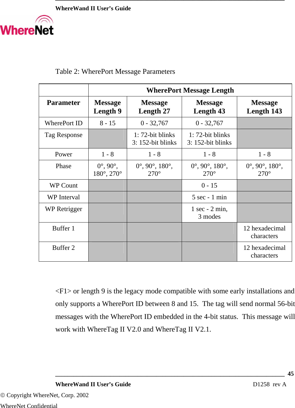
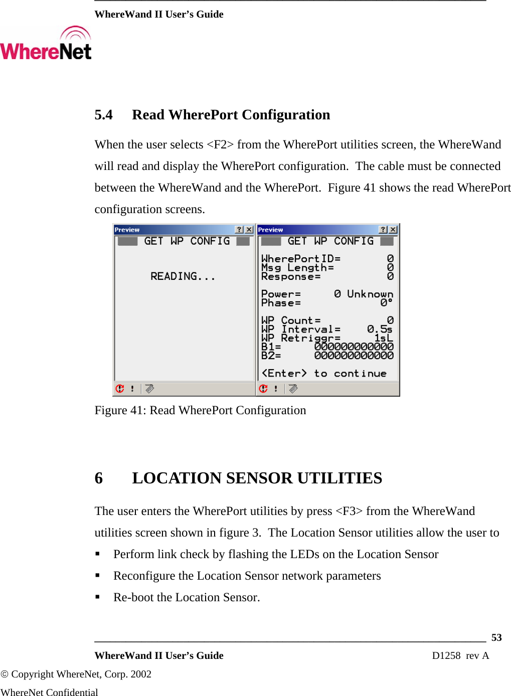
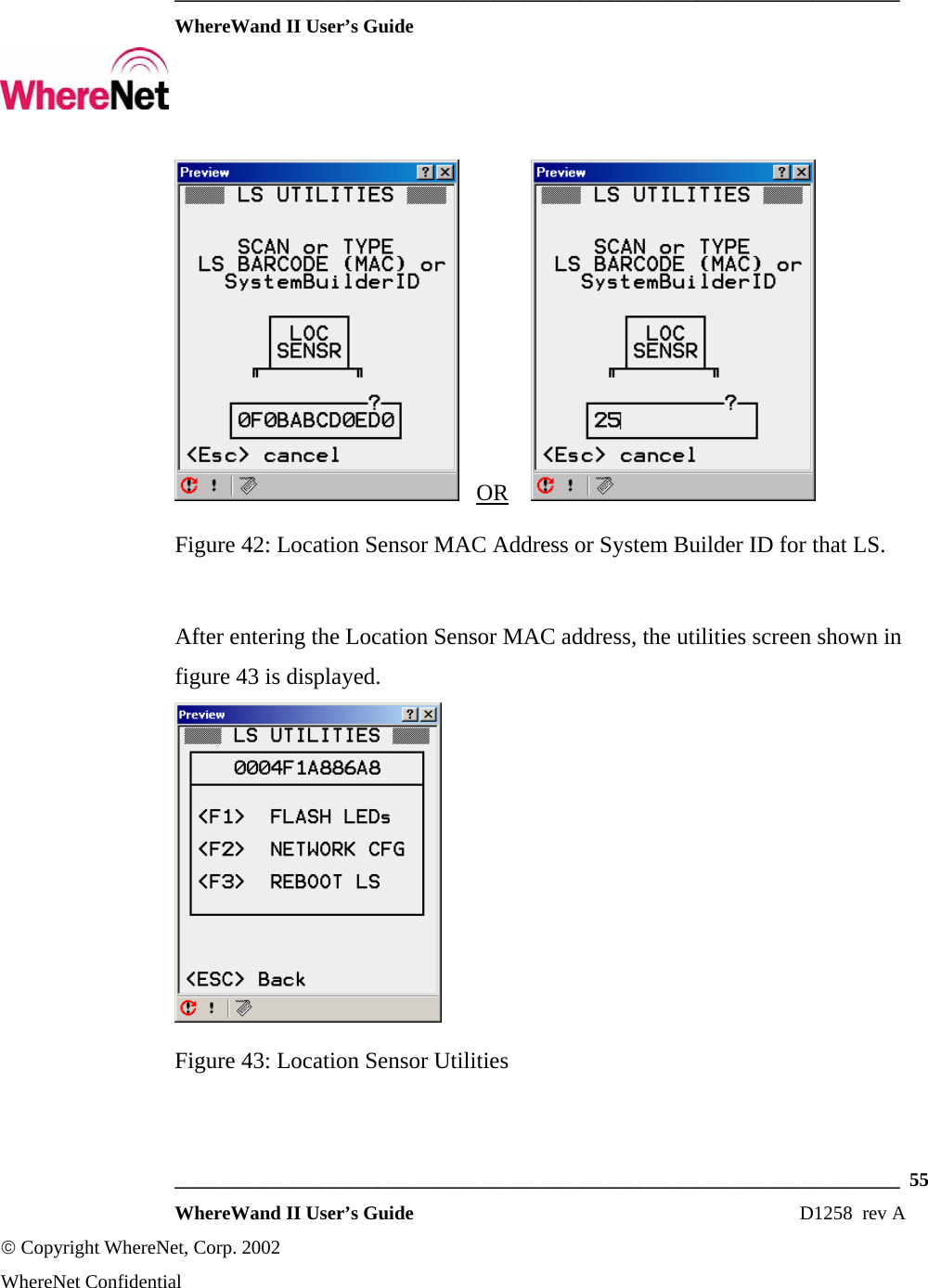
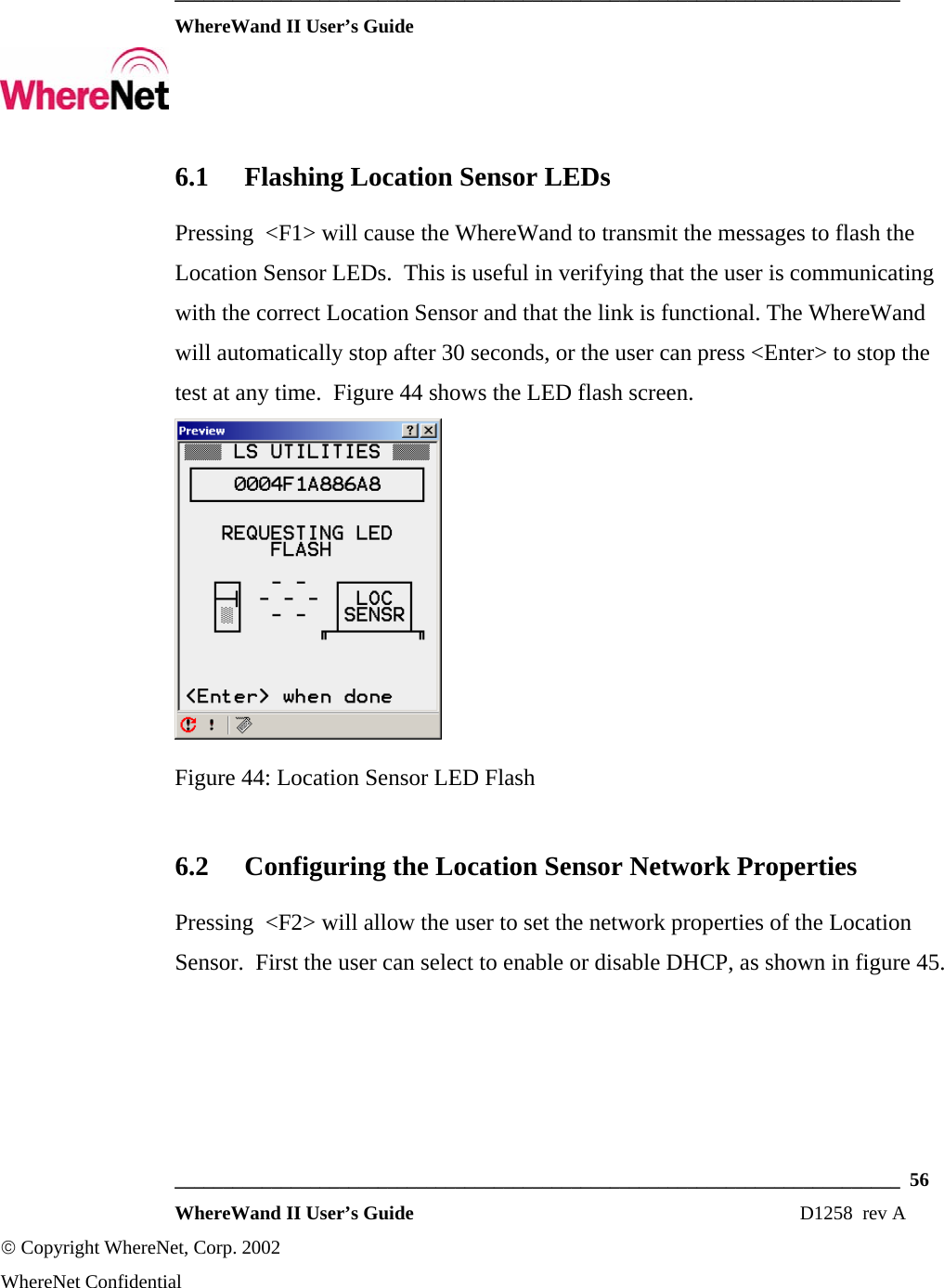
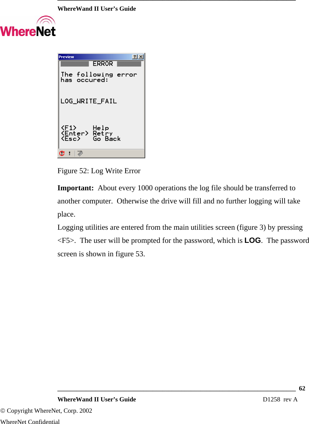
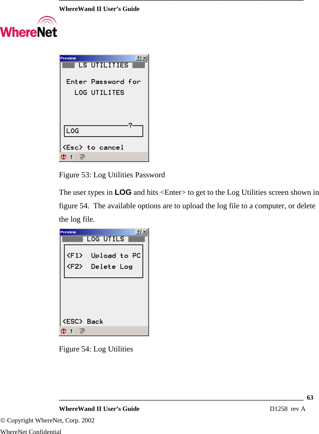
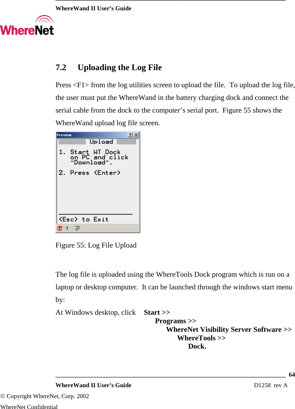
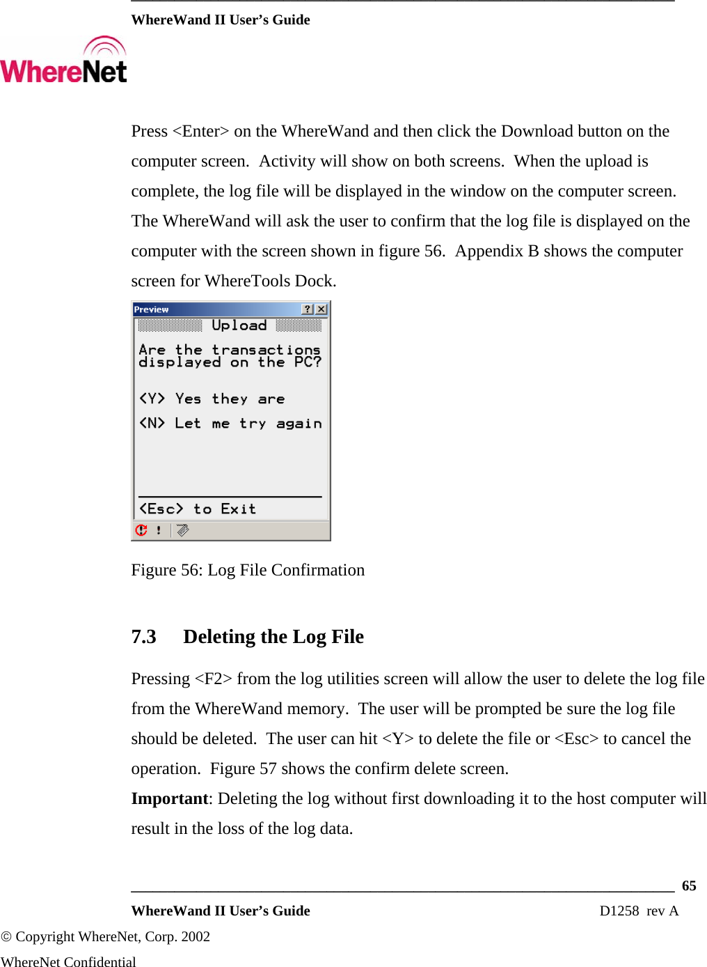
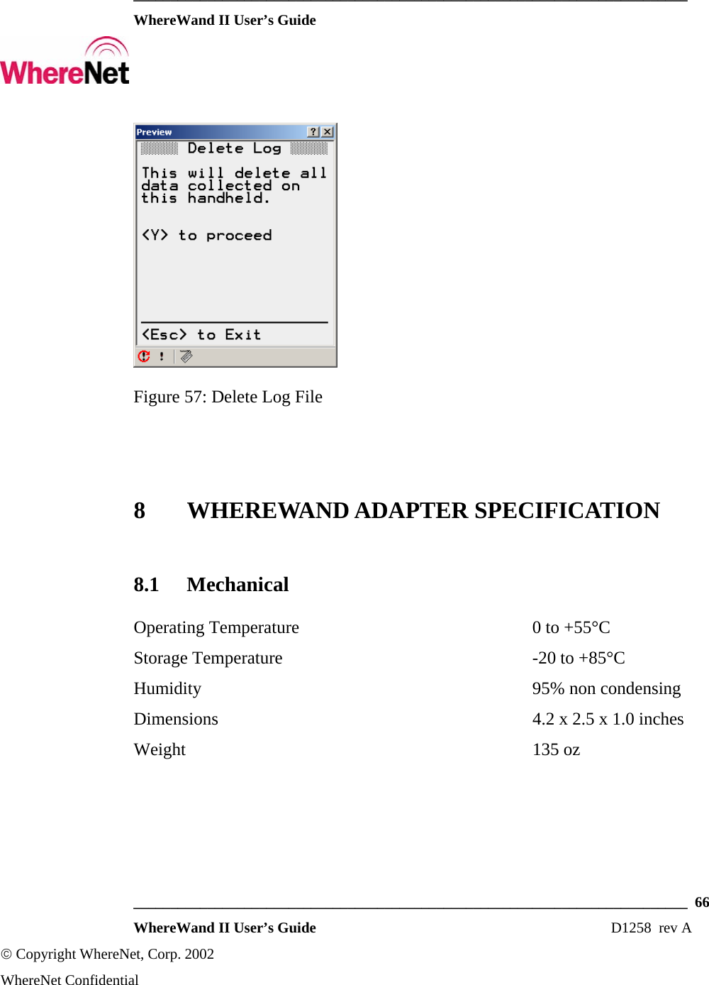
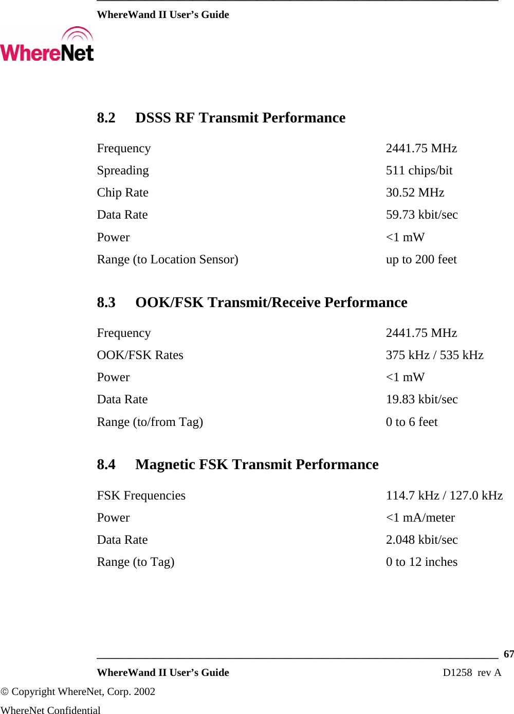
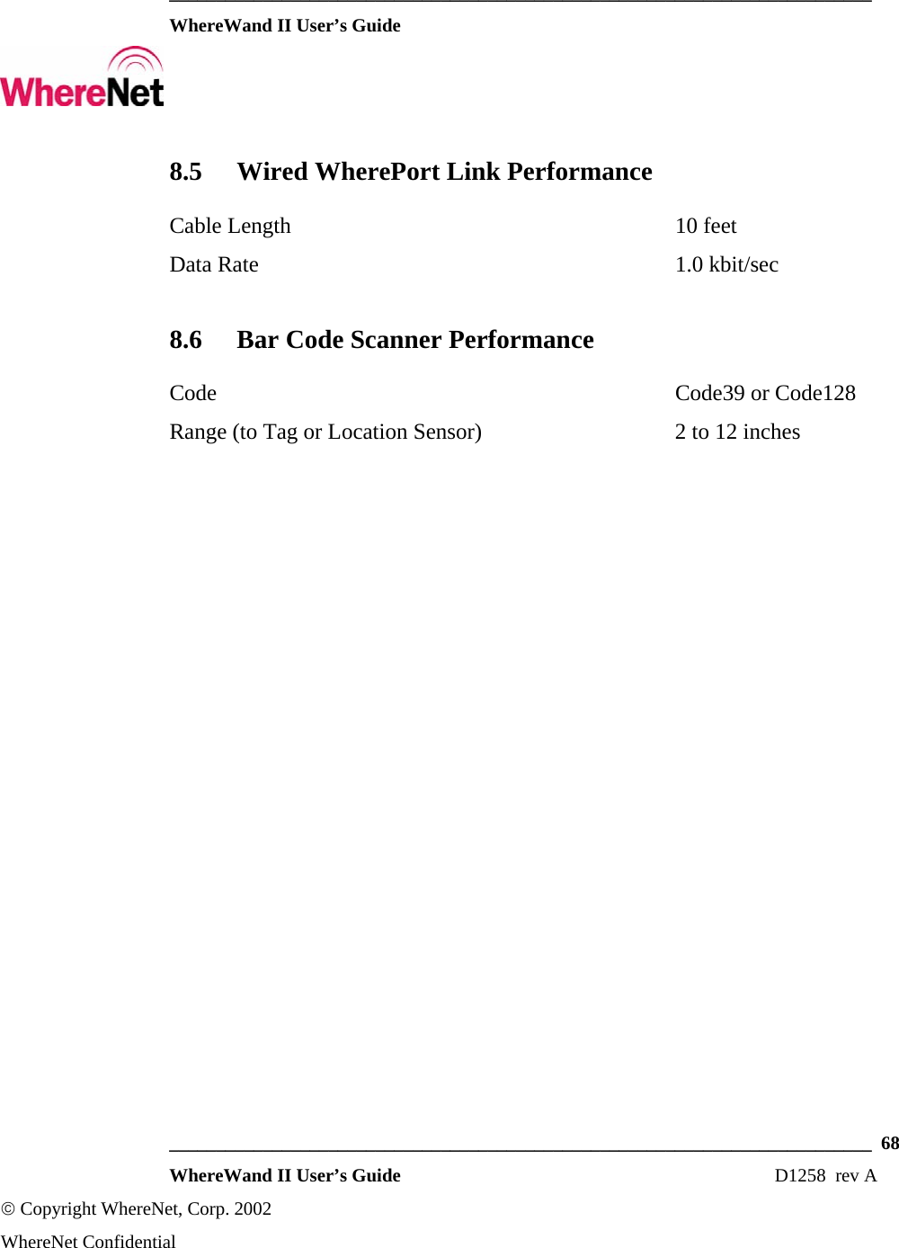
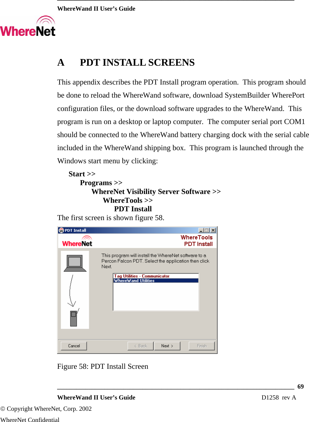
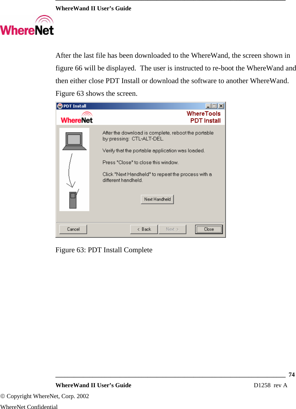
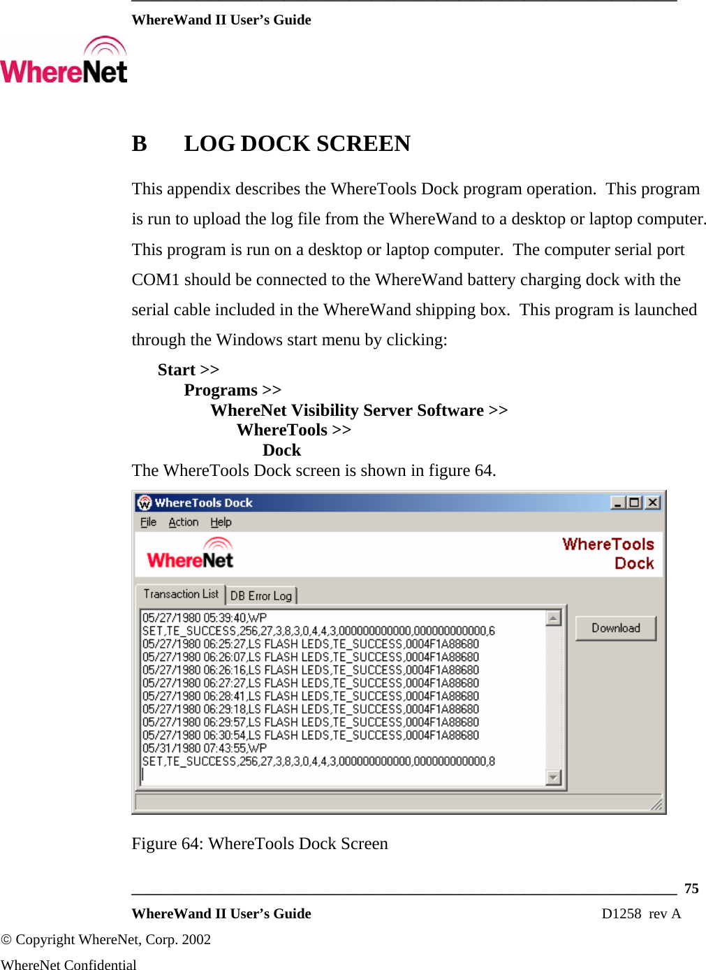
Users Manual
Navigation menu
Upload a User Manual
Namespaces
Wiki Guide
HTML
PDF
Info
Views
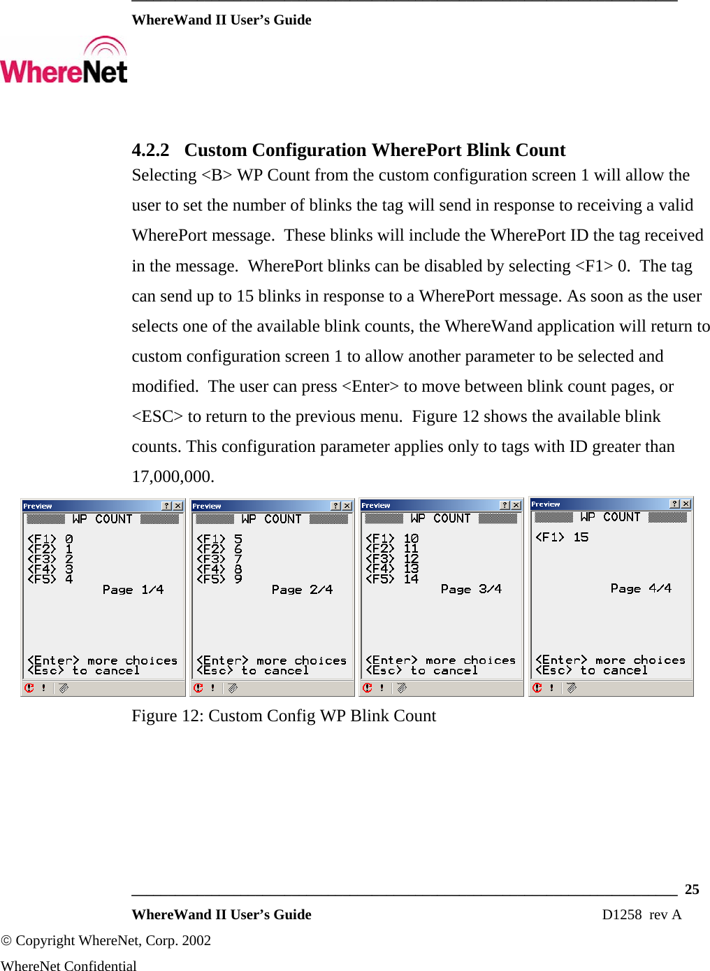
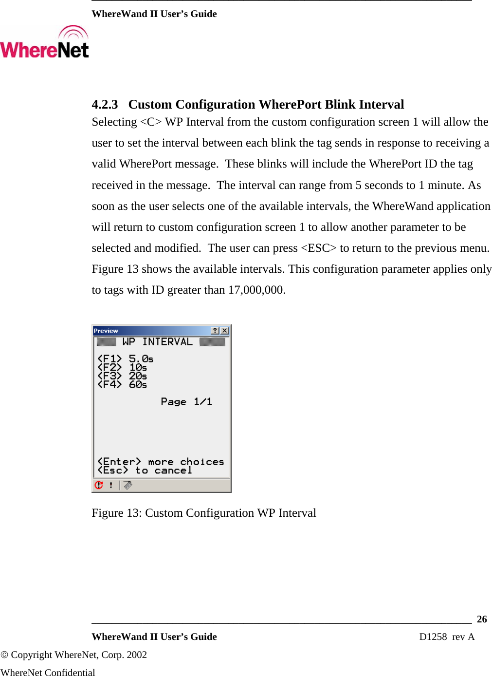
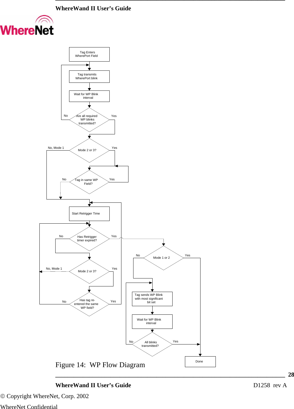
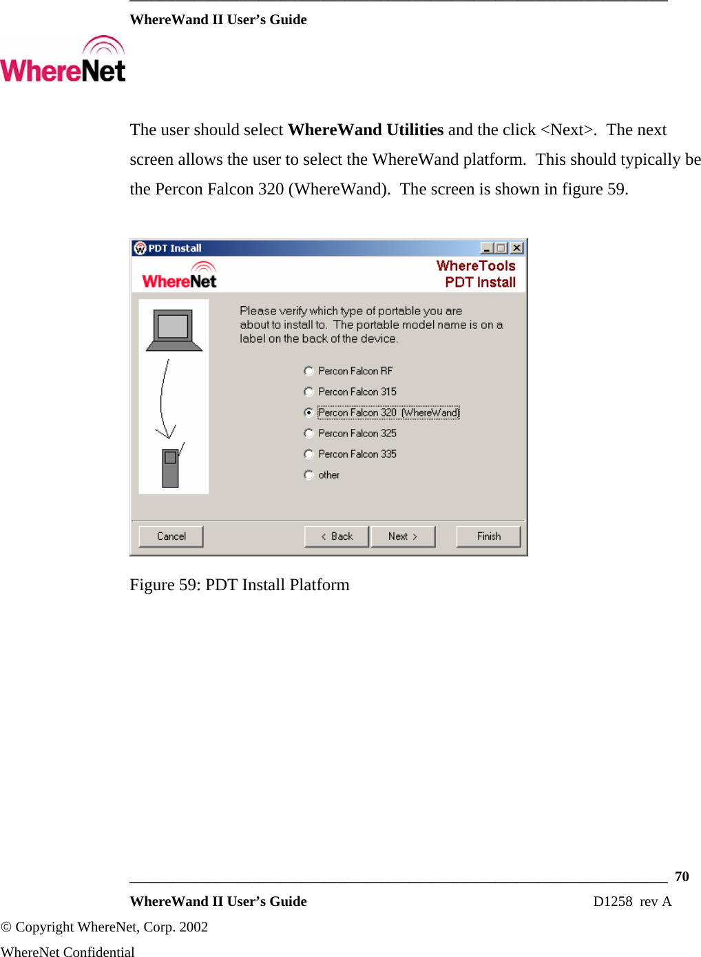
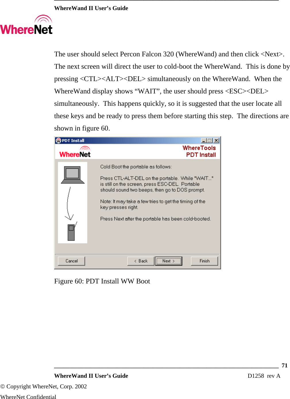
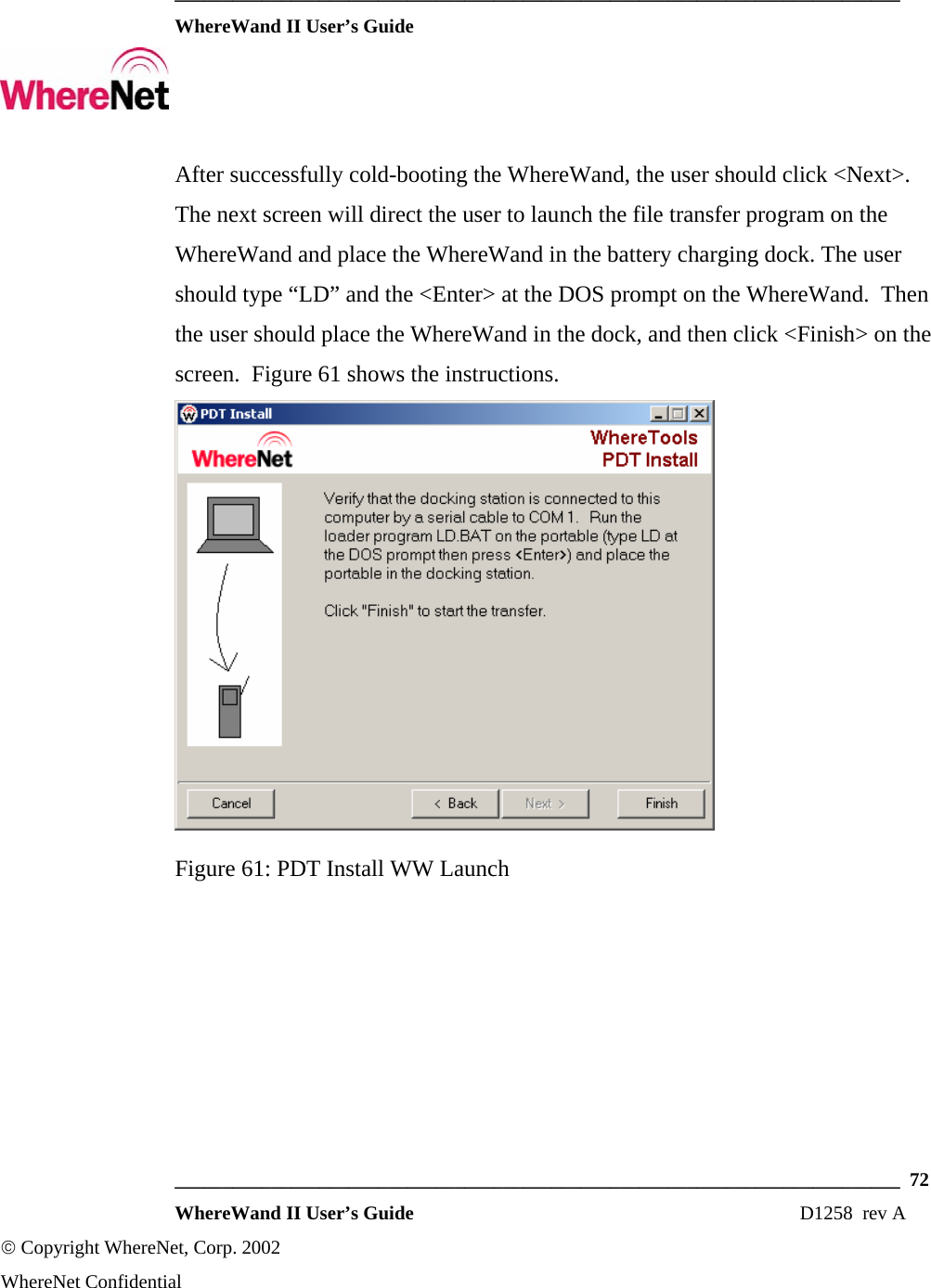
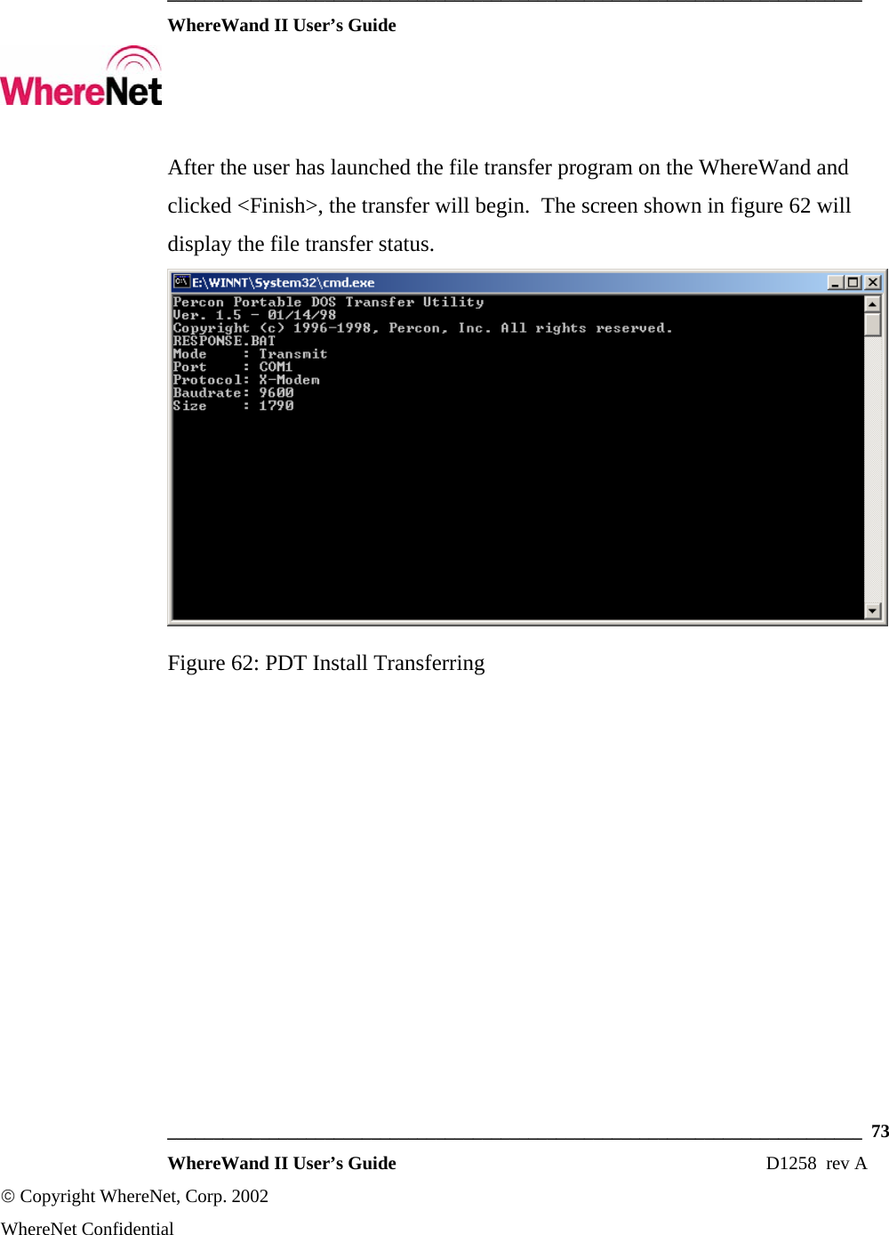
User Manual
Discussion / Help
Navigation