Zebra Technologies WND-2100-00AA WhereWand II Adapter User Manual
Zebra Technologies Corporation WhereWand II Adapter Users Manual
Users Manual

___________________________________________________________________________
WhereWand II User’s Guide
___________________________________________________________________________ 1
WhereWand II User’s Guide D1258 rev A
© Copyright WhereNet, Corp. 2002
WhereNet Confidential
WhereWand II
With VSS 3.1 (or later)
User’s Guide
Configuration Utilities For
WhereTags, WherePorts, and Location Sensors

___________________________________________________________________________
WhereWand II User’s Guide
___________________________________________________________________________ 2
WhereWand II User’s Guide D1258 rev A
© Copyright WhereNet, Corp. 2002
WhereNet Confidential
Typographical Conventions
Warnings call attention to a procedure or practice that could result in
personal injury if not correctly performed. Do not proceed until you fully
understand and meet the required conditions.
Cautions call attention to an operation procedure or practice that could
damage the product, or degrade performance if not correctly performed. Do
not proceed until understanding and meeting these required conditions.
Notes provide information that can be helpful in understanding the operation
of the product.
_____________
_____________
____________
______________
____________
Note
____________

___________________________________________________________________________
WhereWand II User’s Guide
___________________________________________________________________________ 3
WhereWand II User’s Guide D1258 rev A
© Copyright WhereNet, Corp. 2002
WhereNet Confidential
Document Revision History
Revision Description of Changes Date Approved
A Release WhereWand User’s Guide D. Olsen

___________________________________________________________________________
WhereWand II User’s Guide
___________________________________________________________________________ 4
WhereWand II User’s Guide D1258 rev A
© Copyright WhereNet, Corp. 2002
WhereNet Confidential
Table of Contents Page
1 NOTICES AND REQUIREMENTS 9
1.1 FCC REQUIREMENTS 9
1.2 RF NOTICE 10
2 SYSTEM OVERVIEW 10
2.1 WHERENET RLTS SYSTEM 10
2.2 WHEREWAND HAND HELD PROGRAMMER 11
2.3 POWER MANAGEMENT 13
2.4 SOFTWARE REQUIREMENTS 14
2.5 PACKAGE CONTENTS 14
3 OPERATION 14
3.1 CONFIGURATION AND SETUP 14
3.2 STARTING THE WHEREWAND APPLICATION 16
4 WHERETAG/WHERECALL UTILITIES 18
4.1 DEFAULT CONFIGURATIONS 19
4.2 CUSTOM CONFIGURATION 21
4.3 READ TAG CONFIGURATION 35
4.4 TURN TAG OFF 38
5 WHEREPORT UTILITIES 39
5.1 SET WHEREPORT CONFIGURATION 39
5.2 SYSTEMBUILDER WHEREPORT CONFIGURATION 40
5.3 MANUAL WHEREPORT CONFIGURATION 42
5.4 READ WHEREPORT CONFIGURATION 53
6 LOCATION SENSOR UTILITIES 53

___________________________________________________________________________
WhereWand II User’s Guide
___________________________________________________________________________ 5
WhereWand II User’s Guide D1258 rev A
© Copyright WhereNet, Corp. 2002
WhereNet Confidential
6.1 FLASHING LOCATION SENSOR LEDS 56
6.2 CONFIGURING THE LOCATION SENSOR NETWORK PROPERTIES 56
6.3 REBOOTING THE LOCATION SENSOR 59
7 LOGGING 61
7.1 LOG FILE DISK USAGE 61
7.2 UPLOADING THE LOG FILE 64
7.3 DELETING THE LOG FILE 65
8 WHEREWAND SPECIFICATION 66
8.1 MECHANICAL 66
8.2 DSSS RF TRANSMIT PERFORMANCE 67
8.3 OOK/FSK TRANSMIT/RECEIVE PERFORMANCE 67
8.4 MAGNETIC FSK TRANSMIT PERFORMANCE 67
8.5 WIRED WHEREPORT LINK PERFORMANCE 68
8.6 BAR CODE SCANNER PERFORMANCE 68
A PDT INSTALL SCREENS 69
B LOG DOCK SCREEN 75
List of Figures Page
FIGURE 1: LOADING SCREEN 16
FIGURE 2: WELCOME SCREEN 17
FIGURE 3: MAIN UTILITIES MENU SCREEN 17
FIGURE 4: TAG UTILITIES 18
FIGURE 5: SET TAG CONFIGURATION 19
FIGURE 6: WHERETAG DEFAULT CONFIG ID ENTRY SCREEN 20

___________________________________________________________________________
WhereWand II User’s Guide
___________________________________________________________________________ 6
WhereWand II User’s Guide D1258 rev A
© Copyright WhereNet, Corp. 2002
WhereNet Confidential
FIGURE 7: CONFIGURATION SUCCESS 20
FIGURE 8: CUSTOM CONFIG SCREEN 1 21
FIGURE 9: CUSTOM CONFIG SCREEN 2 22
FIGURE 10: CUSTOM CONFIG TAG ID ENTRY 22
FIGURE 11: CUSTOM CONFIG BLINK RATE 24
FIGURE 12: CUSTOM CONFIG WP BLINK COUNT 25
FIGURE 13: CUSTOM CONFIGURATION WP INTERVAL 26
FIGURE 14: WP FLOW DIAGRAM 28
FIGURE 15: CUSTOM CONFIGURATION WP RETRIGGER 29
FIGURE 16: CUSTOM CONFIG SWITCH BLINKS 30
FIGURE 17: CUSTOM CONFIG SWITCH BLINK INTERVAL 30
FIGURE 18: CUSTOM CONFIG SWITCH RETRIGGER 31
FIGURE 19: CUSTOM CONFIG RX WAKEUP 32
FIGURE 20: CUSTOM CONFIG SUB-BLINKS 33
FIGURE 21: CUSTOM CONFIG LONG INTERVAL 34
FIGURE 22: TAG READ ID ENTRY 35
FIGURE 23: WHERECALL READ INFORMATION 36
FIGURE 24: WHERETAG READ INFORMATION 36
FIGURE 25: CONFIGURATION DATA WAS OVERWRITTEN 37
FIGURE 26: TURN TAG OFF ID ENTRY 38
FIGURE 27: WHEREPORT UTILITIES 39
FIGURE 28: SET WHEREPORT CONFIGURATION 40
FIGURE 29: SYSTEMBUILDER WHEREPORT CONFIGURATION 41
FIGURE 30: SB CONFIGURATION CONFIRM 41

___________________________________________________________________________
WhereWand II User’s Guide
___________________________________________________________________________ 7
WhereWand II User’s Guide D1258 rev A
© Copyright WhereNet, Corp. 2002
WhereNet Confidential
FIGURE 31: SB CONFIGURATION ERROR 42
FIGURE 32: MANUAL WHEREPORT CONFIGURATION 43
FIGURE 33: WHEREPORT CONFIGURATION SUCCESS 43
FIGURE 34: WHEREPORT ID 44
FIGURE 35: WHEREPORT MESSAGE LENGTH 47
FIGURE 36: WHEREPORT TAG RESPONSE 47
FIGURE 37: WHEREPORT POWER 48
FIGURE 38: WHEREPORT PHASE 50
FIGURE 39: MULTI-WHEREPORT PHASE EXAMPLE 50
FIGURE 40: WHEREPORT BUFFER 52
FIGURE 41: READ WHEREPORT CONFIGURATION 53
FIGURE 42: LOCATION SENSOR MAC ADDRESS 55
FIGURE 43: LOCATION SENSOR UTILITIES 55
FIGURE 44: LOCATION SENSOR LED FLASH 56
FIGURE 45: LOCATION SENSOR DHCP 57
FIGURE 46: LOCATION SENSOR IP ADDRESS 57
FIGURE 47: LOCATION SENSOR SUBNET MASK AND GATEWAY 58
FIGURE 48: LOCATION SENSOR NETWORK PROPERTIES 58
FIGURE 49: LOCATION SENSOR SENDING 59
FIGURE 50: LOCATION SENSOR CONFIRM REBOOT 60
FIGURE 51: LOCATION SENSOR REBOOTING 60
FIGURE 52: LOG WRITE ERROR 62
FIGURE 53: LOG UTILITIES PASSWORD 63
FIGURE 54: LOG UTILITIES 63

___________________________________________________________________________
WhereWand II User’s Guide
___________________________________________________________________________ 8
WhereWand II User’s Guide D1258 rev A
© Copyright WhereNet, Corp. 2002
WhereNet Confidential
FIGURE 55: LOG FILE UPLOAD 64
FIGURE 56: LOG FILE CONFIRMATION 65
FIGURE 57: DELETE LOG FILE 66
FIGURE 58: PDT INSTALL SCREEN 69
FIGURE 59: PDT INSTALL PLATFORM 70
FIGURE 60: PDT INSTALL WW BOOT 71
FIGURE 61: PDT INSTALL WW LAUNCH 72
FIGURE 62: PDT INSTALL TRANSFERRING 73
FIGURE 63: PDT INSTALL COMPLETE 74
FIGURE 64: WHERETOOLS DOCK SCREEN 75
List of Tables Page
TABLE 1: CUSTOM CONFIGURATION PARAMETERS 23
TABLE 2: WHEREPORT MESSAGE PARAMETERS 45
TABLE 3: WHEREPORT POWER VS. RANGE 49

___________________________________________________________________________
WhereWand II User’s Guide
___________________________________________________________________________ 9
WhereWand II User’s Guide D1258 rev A
© Copyright WhereNet, Corp. 2002
WhereNet Confidential
1 NOTICES AND REQUIREMENTS
1.1 FCC Requirements
This device complies with Part 15 of FCC (Federal Communication Commission)
rules. See FCC registration label, located on the bottom of the equipment for the
FCC registration. Operation is subject to the following two conditions:
1) this device may not cause harmful interference, and
2) this device must accept any interference received, including interference that
may cause undesired operation.
This equipment has been tested and found to comply with the limits of Class B
devices, pursuant to Part 15 of the FCC Rules.
This Class B digital apparatus complies with Canadian ICES-003.
Cet appareil numerique de la class B est conforme a la norme NMB-003 du
Canada.
Radio Equipment Authorization: FCC ID: NSQWND-2100-00AA
IC: 3586B-WND2100

___________________________________________________________________________
WhereWand II User’s Guide
___________________________________________________________________________ 10
WhereWand II User’s Guide D1258 rev A
© Copyright WhereNet, Corp. 2002
WhereNet Confidential
1.2 RF Notice
The antenna used for this transmitter must not be co-located or operating in
conjunction with any other antenna or transmitter.
Any changes or modifications to WhereNet Corporation equipment not expressly
approved by WhereNet Corporation could void the user’s authority to operate the
equipment.
2 SYSTEM OVERVIEW
2.1 WhereNet RLTS System
The WhereNet real time location system (RTLS) is designed to permit users to
determine the position of tagged assets in both indoor and outdoor applications.
Each WhereTag autonomously emits a 2.4 GHz direct sequence spread spectrum
(DSSS) radio signal at predetermined blink intervals, in response to switch events,
and/or in response to WherePort devices. The signal transmitted by the WhereTag
is received by the WhereNet infrastructure which decodes that tag’s transmission,
extracts the data, and determines the tag’s location using several different
algorithms.

___________________________________________________________________________
WhereWand II User’s Guide
___________________________________________________________________________ 11
WhereWand II User’s Guide D1258 rev A
© Copyright WhereNet, Corp. 2002
WhereNet Confidential
The WhereNet RLTS consists of WhereTag/WhereCall tags, WherePorts,
WhereWands, Location Sensors, and the server based Visibility Suite software.
WherePorts generate a magnetic field in a localized area. WherePort devices can
be used in places where the user wants to know immediately that the tagged asset
has entered the zone covered by the WherePort field. The WhereTag devices can
be configured to blink rapidly several times when they enter a WherePort field.
When the tag blinks in response to entering a WherePort field, the ID of the
WherePort is included in the tag transmission.
WhereWands are used to configure WhereTags, WhereCalls, WherePorts, and
Location Sensors. This document will detail the operation and use of the
WhereWand.
Location Sensors receive DSSS blinks from the tags and demodulate the signal,
time stamp the blink, and send the tag ID and any associated data included in the
blink to the server over the LAN.
2.2 WhereWand Hand Held Programmer
All references to the WhereWand product in this document assume VSS 3.0
(or greater) Tag Utilities are loaded on the WhereWand; prior versions of the
Tag Utilities do not support all features listed in this document.
____________
Note
____________

___________________________________________________________________________
WhereWand II User’s Guide
___________________________________________________________________________ 12
WhereWand II User’s Guide D1258 rev A
© Copyright WhereNet, Corp. 2002
WhereNet Confidential
The WhereWand Hand Held Programmer consists of Handheld Computer with an
external WhereWand adapter with an integral antenna assembly. The WhereWand
is capable of two-way wireless communication with WhereTag and WhereCall tag
devices. The WhereWand is also capable of wired communication with
WherePort devices. The third capability of the WhereWand is wireless
communications with the Location Sensor in the WhereNet G2 infrastructure.
The WhereWand communicates with WhereTag II/III/IV devices by sending
magnetic FSK data to the tag and receiving on-off keyed / frequency shift keyed
(OOK/FSK) RF data from the tag. The WhereWand communicates with
WhereCall and WhereTag I devices by transmitting and receiving OOK/FSK RF
data to and from the tag. Communication with the WhereTag and WhereCall
allow the user to set tag configuration parameters such as DSSS blink intervals and
tag responses to such stimuli as WherePorts and/or switch/telemetry inputs. It also
allows the user to read back configuration and other data from the tag. The
WhereWand will automatically select the proper communication protocol scheme
based on the tag’s unique identification number
Tag IDs between 0 and 16,777,215 are WhereCall or WhereTag I
Tag IDs between 16,777,216 and 17,099,999 are WhereTag II V2.0
Tag IDs between 17,100,000 and 17,999,999 are WhereTag II V2.1
Tag IDs greater than 18,000,000 are WhereTag III or IV devices
The WhereWand communicates with WherePort II or III devices using the
configuration cable included with the WhereWand. This bi-directional interface

___________________________________________________________________________
WhereWand II User’s Guide
___________________________________________________________________________ 13
WhereWand II User’s Guide D1258 rev A
© Copyright WhereNet, Corp. 2002
WhereNet Confidential
allows the user to configure WherePort devices and read back the configuration.
WherePort configuration parameters include WherePort ID, power level, phase
setting, and tag response.
The WhereWand communicates with the Location Sensor by transmitting DSSS
messages containing the desired configuration data or test mode. This is a transmit
only operation and the Location Sensor will not transmit anything back to the
WhereWand, but the Location Sensor will flash its LEDs to indicate
communications are in progress.
2.3 Power Management
The WhereWand II’s power management is handled by the application software
installed on the handheld computer. The WhereWand II Adapter PCBA itself will
shut off the on-board high frequency RF clock while it is not transmitting to
further reduce current consumption. The WhereWand II Adapter ships with
rechargeable Lithium batteries.
Any time the WhereWand Programmer is not in use, it should be placed into its
battery charger cradle. Refer to the terminal’s Original Equipment Manufacturer
documentation included with the product.

___________________________________________________________________________
WhereWand II User’s Guide
___________________________________________________________________________ 14
WhereWand II User’s Guide D1258 rev A
© Copyright WhereNet, Corp. 2002
WhereNet Confidential
2.4 Software Requirements
WhereNet Corporation has developed and installed the software to ensure that the
WhereNet Adapter unit is recognized by the handheld computer, that the
appropriate I/O and memory resources are allocated, and the user application
software will operate.
2.5 Package Contents
WhereWand II Programmer Handheld Computer
Handheld serial port adapter
Docking Station / Battery Charger
Power Supply for docking station
Serial cable for downloading software to the handheld computer
WhereWand II Adapter unit
Connection cable from handheld to WhereWand II Adapter unit/battery pack
Configuration cable for WhereWand II to WherePort II/III communications
Carrying Case for WhereWand II Adapter and battery pack
Software installation diskette
3 OPERATION
3.1 Configuration and Setup

___________________________________________________________________________
WhereWand II User’s Guide
___________________________________________________________________________ 15
WhereWand II User’s Guide D1258 rev A
© Copyright WhereNet, Corp. 2002
WhereNet Confidential
The WhereWand II Programmer does not require any special configuration or
setup to operate with the application software loaded on the handheld computer.
The software is stored in non-volatile memory in the WhereWand. If the
WhereWand is left off for long periods of time without being placed in the battery
charging cradle, it is possible that the backup battery used to keep the memory
may completely discharge. If this does happen, the software can be reloaded using
the WhereTools PDT Installer included with VSS. This program is run on a laptop
or desktop computer connected to the battery charging dock with the serial cable.
___________________________________________________________________________
WhereWand II User’s Guide
___________________________________________________________________________ 16
WhereWand II User’s Guide D1258 rev A
© Copyright WhereNet, Corp. 2002
WhereNet Confidential
The PDT Installer can be launched through the Microsoft Windows start menu by:
At Windows desktop, click Start >>
Programs >>
WhereNet Visibility Server Software >>
WhereTools >>
PDT Install.
Then select WhereWand Utilities and then click the Next button and follow the
on screen instructions as shown in Appendix A.
3.2 Starting the WhereWand Application
The WhereWand Programmer application software should automatically run on
power up of the handheld computer. Typing “HH” from the DOS C:\ prompt will
also start the application software. As the program is loading, the screen shown in
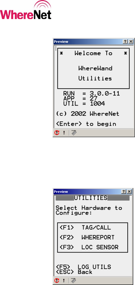
figure 1 is displayed. Once the program is loaded, the welcome screen shown in
figure 2 will be displayed.
Figure 1: Loading Screen
___________________________________________________________________________
WhereWand II User’s Guide
___________________________________________________________________________ 17
WhereWand II User’s Guide D1258 rev A
© Copyright WhereNet, Corp. 2002
WhereNet Confidential
Figure 2: Welcome Screen
The user presses the <Enter> key on the handheld to bring up the WhereWand
utilities main menu. The main menu is shown in figure 3.
Figure 3: Main Utilities Menu Screen
___________________________________________________________________________
WhereWand II User’s Guide
___________________________________________________________________________ 18
WhereWand II User’s Guide D1258 rev A
© Copyright WhereNet, Corp. 2002
WhereNet Confidential
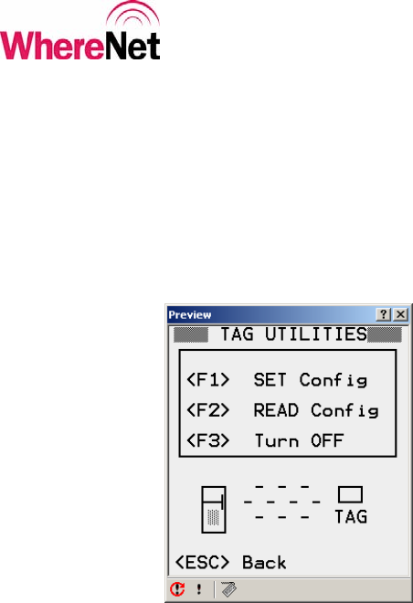
4 WHERETAG/WHERECALL UTILITIES
The user enters the WhereTag / WhereCall utilities by pressing <F1> from the
main utilities screen. The WhereTag / WhereCall utilities allow the user to
configure and read tags. The tag utilities screen is shown in figure 4.
Figure 4: Tag Utilities
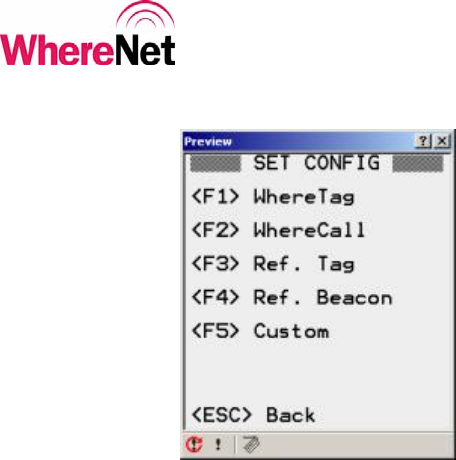
Pressing <F1> puts the user into the set configuration mode. The user can select
from one of the default configuration tag types or set up a custom configuration.
Figure 5 shows the set configuration options. The WhereWand will automatically
determine the correct protocol for communicating with the WhereTag or
WhereCall based on the tag’s unique identification on the bar code label.
___________________________________________________________________________
WhereWand II User’s Guide
___________________________________________________________________________ 19
WhereWand II User’s Guide D1258 rev A
© Copyright WhereNet, Corp. 2002
WhereNet Confidential
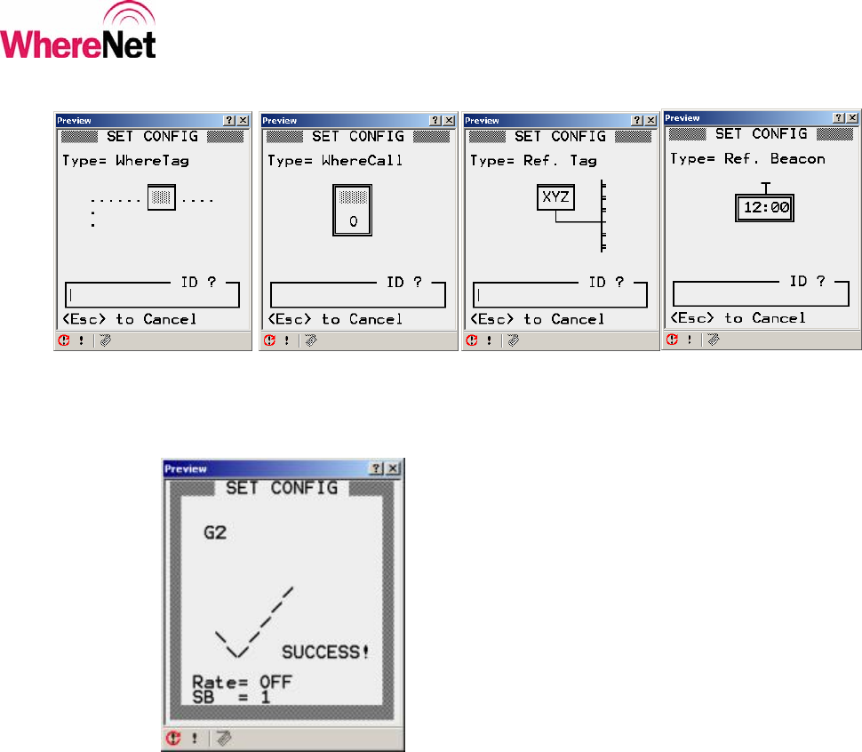
Figure 5: Set Tag Configuration
4.1 Default Configurations
Selecting one of the default configurations options <F1> through <F4> from SET
CONFIG screen will bring up the appropriate tag ID entry screen. The user can
either scan the tag bar code with the laser scanner on the WhereWand, or manually
type the tag ID using the WhereWand keypad and then hitting <Enter>. The
WhereWand will then open the tag communications link and send the default
configuration. Once the tag has been successfully configured, the WhereWand
will indicate the status of the communications. Figure 6 shows the default
configuration tag ID entry screens. Figure 7 shows the communications success
screen. To see what the default configuration settings are, the user can configure a
tag and then read the configuration back.
___________________________________________________________________________
WhereWand II User’s Guide
___________________________________________________________________________ 20
WhereWand II User’s Guide D1258 rev A
© Copyright WhereNet, Corp. 2002
WhereNet Confidential
Figure 6: WhereTag Default Config ID Entry Screen
Figure 7: Configuration Success
___________________________________________________________________________
WhereWand II User’s Guide
___________________________________________________________________________ 21
WhereWand II User’s Guide D1258 rev A
© Copyright WhereNet, Corp. 2002
WhereNet Confidential
4.2 Custom Configuration
Select Custom <F5> from the SET CONFIG screen will allow the user to
configure all of the available tag parameters to meet unique application
requirements. Table 1 describes each of the configurable parameters that the user
can access through the screens shown in figures 8 and 9. Figure 10 shows the tag
ID entry screen. The user can move between screens shown in figures 8 through
10 using <Enter> and <Esc>. Once the user has changed the desired parameter
and presses <Enter> the WhereWand will bring up the tag ID entry screen. The
user can either scan the tag bar code with the laser scanner on the WhereWand, or
manually type the tag ID using the WhereWand keypad and then hitting <Enter>.
The WhereWand will then open the tag communications link and send the custom
configuration. Once the tag has been successfully configured, the WhereWand
will indicate the status of the communications.
Figure 8: Custom Config Screen 1
___________________________________________________________________________
WhereWand II User’s Guide
___________________________________________________________________________ 22
WhereWand II User’s Guide D1258 rev A
© Copyright WhereNet, Corp. 2002
WhereNet Confidential
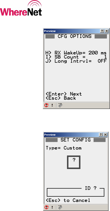
Figure 9: Custom Config Screen 2
Figure 10: Custom Config Tag ID Entry

___________________________________________________________________________
WhereWand II User’s Guide
___________________________________________________________________________ 23
WhereWand II User’s Guide D1258 rev A
© Copyright WhereNet, Corp. 2002
WhereNet Confidential
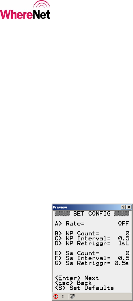
Table 1: Custom Configuration Parameters
Key Parameter Description
<A> Rate The interval between tag’s normal keep alive blinks.
-> Range is from OFF to 5 seconds to 1 Hour
<B> WP Count The number of blinks the tag transmits in response to receiving a
valid WherePort message.
-> Range is from 0 to 15 blinks
<C> WP Interval The time between each of the WherePort blinks.
-> Range is 5 seconds to 1 minute.
<D> WP Retrigger Set the time after blinking in response to a WherePort that the same
WherePort ID is ignored and will not cause more tag blinks.
-> Range is 1 second to 2 minutes, with 3 different modes.
<E> Sw Count The number of blinks the tag transmits in response to a level change
on one of its switch or telemetry inputs.
-> Range is from 0 to 15 blinks.
<F> Sw Interval The time between each of the switch event blinks
-> Range is 5 seconds to 1 minute.
<G> Sw Retrigger The time after blinking in response to a switch event that the same
event will be ignored and will not cause more tag blinks
->Range is ½ second to 1 minute.
<H> RX Wakeup Select between 200 msec and 500 msec receiver on interval
<I> SB Count Set the number of sub-blinks the tag sends in every blink
-> Range is 1 to 8 sub-blinks.
<J> Long Intrvl Allows the tag to periodically send normal mode blinks with 12
bytes of data appended to the blink
-> Settings are never, every 8th or 64th blink, or with every blink
More detail on the settings for each parameter is given in the following sections.
___________________________________________________________________________
WhereWand II User’s Guide
___________________________________________________________________________ 24
WhereWand II User’s Guide D1258 rev A
© Copyright WhereNet, Corp. 2002
WhereNet Confidential
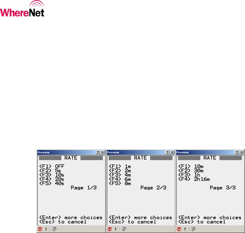
4.2.1 Custom Configuration Blink Rate
Selecting <A> Rate from the custom configuration screen 1 will allow the user to
set the interval between normal keep alive blinks that the tag transmits and the
infrastructure receives for locating the tag and collecting data from the tag. The
normal keep alive blinks can be turned off by selecting <F1> OFF. The interval
can range from 5 seconds up to over 2 hours (depending on tag type). As soon as
the user selects one of the available intervals, the WhereWand application will
return to custom configuration screen 1 to allow another parameter to be selected
and modified. The user can press <Enter> to move between rate pages, or <ESC>
to return to the previous menu. Figure 11 shows the blink interval settings
available to the user.
Figure 11: Custom Config Blink Rate
___________________________________________________________________________
WhereWand II User’s Guide
___________________________________________________________________________ 25
WhereWand II User’s Guide D1258 rev A
© Copyright WhereNet, Corp. 2002
WhereNet Confidential
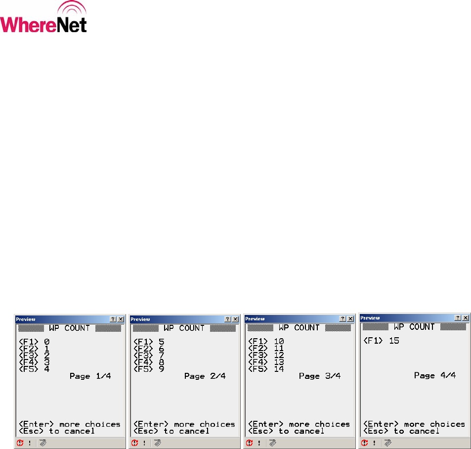
4.2.2 Custom Configuration WherePort Blink Count
Selecting <B> WP Count from the custom configuration screen 1 will allow the
user to set the number of blinks the tag will send in response to receiving a valid
WherePort message. These blinks will include the WherePort ID the tag received
in the message. WherePort blinks can be disabled by selecting <F1> 0. The tag
can send up to 15 blinks in response to a WherePort message. As soon as the user
selects one of the available blink counts, the WhereWand application will return to
custom configuration screen 1 to allow another parameter to be selected and
modified. The user can press <Enter> to move between blink count pages, or
<ESC> to return to the previous menu. Figure 12 shows the available blink
counts. This configuration parameter applies only to tags with ID greater than
17,000,000.
Figure 12: Custom Config WP Blink Count
___________________________________________________________________________
WhereWand II User’s Guide
___________________________________________________________________________ 26
WhereWand II User’s Guide D1258 rev A
© Copyright WhereNet, Corp. 2002
WhereNet Confidential
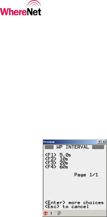
4.2.3 Custom Configuration WherePort Blink Interval
Selecting <C> WP Interval from the custom configuration screen 1 will allow the
user to set the interval between each blink the tag sends in response to receiving a
valid WherePort message. These blinks will include the WherePort ID the tag
received in the message. The interval can range from 5 seconds to 1 minute. As
soon as the user selects one of the available intervals, the WhereWand application
will return to custom configuration screen 1 to allow another parameter to be
selected and modified. The user can press <ESC> to return to the previous menu.
Figure 13 shows the available intervals. This configuration parameter applies only
to tags with ID greater than 17,000,000.
Figure 13: Custom Configuration WP Interval

___________________________________________________________________________
WhereWand II User’s Guide
___________________________________________________________________________ 27
WhereWand II User’s Guide D1258 rev A
© Copyright WhereNet, Corp. 2002
WhereNet Confidential
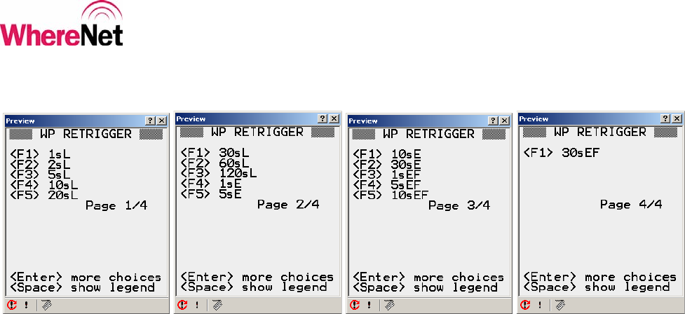
4.2.4 Custom Configuration WherePort Retrigger
Selecting <D> WP Retrigger from the custom configuration screen 1 will allow
the user to set the WherePort retrigger timeout and mode. The same WherePort ID
will be ignored after causing tag blinks until the retrigger timeout expires. The
mode selects the event that starts the timer. In retrigger mode 1 (values with ‘L’
added to the time in seconds) the retrigger timer starts after the tag sends its last
WherePort blink from the previously received valid WherePort message. In
retrigger mode 2 (values with ‘E’ added to the time in seconds) the retrigger timer
will not start until the sends its last WherePort blink AND the tag has left the
WherePort field. If the same WherePort message is received before the timer
expires, the time is reloaded and the retrigger timeout starts over. In retrigger
mode 3 (values with ‘EF’ added to the time in seconds) the retrigger timer operates
the same as in mode 2, only when the timer does expire, the tag will send another
set of WherePort blinks – with the “LEFT WP FIELD” bit set. The retrigger times
can range from 1 second to 2 minutes. As soon as the user selects one of the
available timeouts, the WhereWand application will return to custom configuration
screen 1 to allow another parameter to be selected and modified. The user can
press <Enter> to move to between the WherePort retrigger pages, or <ESC> to
return to the previous menu. Anytime the tag enters the field of a different
WherePort, the blinks and retrigger from the previous WherePort are aborted and
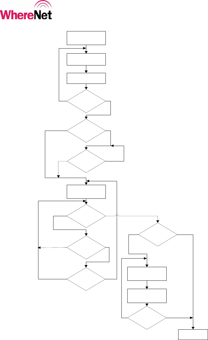
the process begins for the new WherePort. Figure 14 shows the flow diagram of
the blinks and retrigger for one WherePort. Figure 15 shows the available
retrigger times. This configuration parameter applies only to tags with ID greater
than 17,000,000.
___________________________________________________________________________
WhereWand II User’s Guide
___________________________________________________________________________ 28
WhereWand II User’s Guide D1258 rev A
© Copyright WhereNet, Corp. 2002
WhereNet Confidential
Figure 14: WP Flow Diagram
Tag Enters
WherePort Field
Tag transmits
WherePort blink
Are all required
WP blinks
transmitted?
Tag in same WP
Field?
Yes
Start Retrigger Time
Has Retrigger
timer expired?
No
Mode 2 or 3?
No, Mode 1 Yes
YesNo
Has tag re-
entered the same
WP field?
All blinks
transmitted?
No
Mode 2 or 3?
Yes
Yes
YesNo, Mode 1
Done
Mode 1 or 2
Yes
YesNo
Tag sends WP Blink
with most significant
bit set
Wait for WP Blink
interval
No
Wait for WP Blink
interval
No
___________________________________________________________________________
WhereWand II User’s Guide
___________________________________________________________________________ 29
WhereWand II User’s Guide D1258 rev A
© Copyright WhereNet, Corp. 2002
WhereNet Confidential
Figure 15: Custom Configuration WP Retrigger
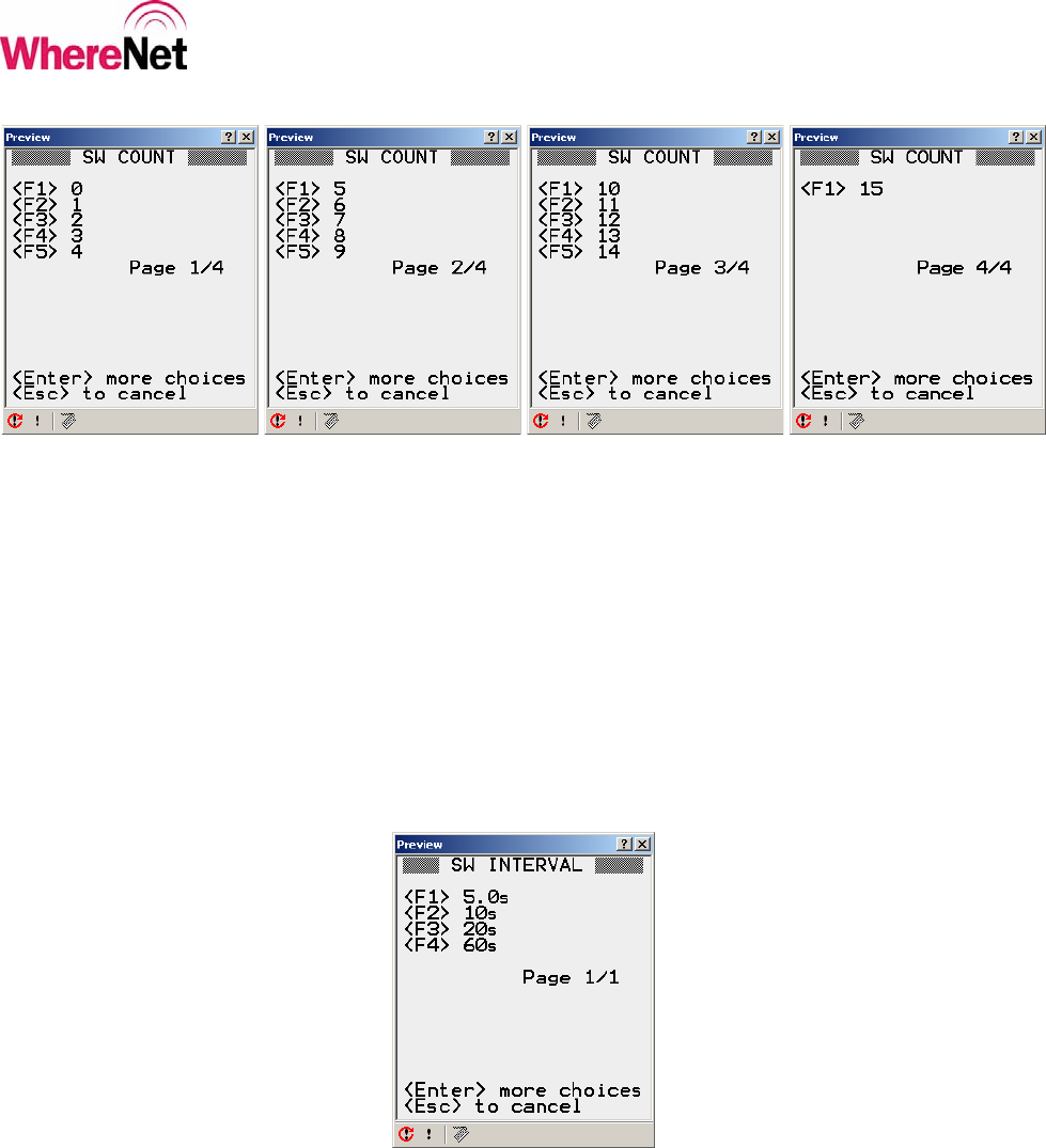
4.2.5 Custom Configuration Switch Blink Count
Selecting <E> Sw Count from the custom configuration screen 1 will allow the
user to set the number of blinks the tag sends in response to a level change on one
of its switch or telemetry inputs. Switch event blinks can be disabled by selected
<F1> 0. The tag can send up to 15 blinks in response to a switch event message.
As soon as the user selects a blink count, the WhereWand application will return to
custom configuration screen 2 to allow another parameter to be selected and
modified. The user can press <Enter> to go between the blink count pages, or
<ESC> to return to the previous menu. Figure 16 shows the available counts.
This configuration parameter applies only to tags with ID greater than 17,000,000.
___________________________________________________________________________
WhereWand II User’s Guide
___________________________________________________________________________ 30
WhereWand II User’s Guide D1258 rev A
© Copyright WhereNet, Corp. 2002
WhereNet Confidential
Figure 16: Custom Config Switch Blinks
4.2.6 Custom Configuration Switch Blink Interval
Selecting <F> Sw Interval from the custom configuration screen 1 will allow the
user to set the interval between switch event blinks. As soon as the user selects an
interval, the WhereWand application will return to custom configuration screen 2
to allow another parameter to be selected and modified. The user can press
<ESC> to return to the previous menu. Figure 17 shows the available intervals.
This configuration parameter applies only to tags with ID greater than 17,000,000.
Figure 17: Custom Config Switch Blink Interval
___________________________________________________________________________
WhereWand II User’s Guide
___________________________________________________________________________ 31
WhereWand II User’s Guide D1258 rev A
© Copyright WhereNet, Corp. 2002
WhereNet Confidential
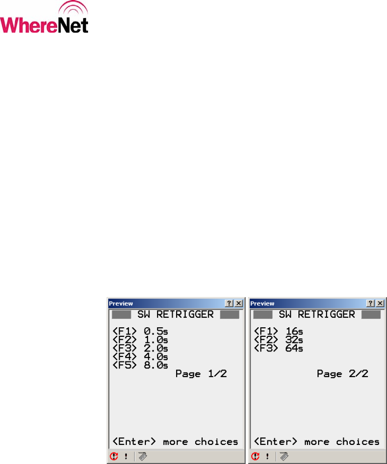
4.2.7 Custom Configuration Switch Retrigger
Selecting <G> Sw Retrigger from the custom configuration screen 1 will allow the
user to set the switch event retrigger time. The same switch event will be ignored
until the retrigger timer expires. The timer starts after the tag has sent its last
switch event blink. The retrigger times range from 1 second to over 1 minute. As
soon as the user selects a retrigger time, the WhereWand application will return to
custom configuration screen 2 to allow another parameter to be selected and
modified. The user can press <Enter> to go between the retrigger pages, or
<ESC> to return to the previous menu. Figure 18 shows the available intervals.
This configuration parameter applies only to tags with ID greater than 17,000,000.
Figure 18: Custom Config Switch Retrigger
___________________________________________________________________________
WhereWand II User’s Guide
___________________________________________________________________________ 32
WhereWand II User’s Guide D1258 rev A
© Copyright WhereNet, Corp. 2002
WhereNet Confidential
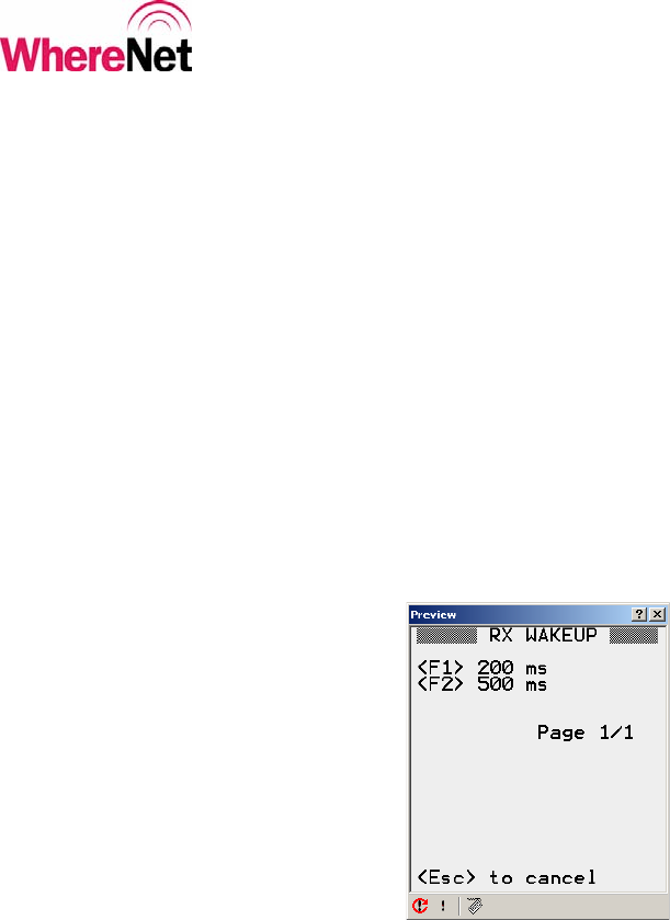
4.2.8 Custom Configuration Receiver Wakeup Interval
Selecting <H> RX Wakeup from the custom configuration screen 2 will allow the
user to set the receiver wakeup interval for the tag. The user can select 200 or 500
milliseconds. As soon as the user selects an interval, the WhereWand application
will return to custom configuration screen 2 to allow another parameter to be
selected and modified. The user can press <ESC> to return to the previous menu.
Figure 19 shows the RX wakeup screen.
Setting the receiver wakeup interval to 500 msec will result in significant
degradation in WhereWand - to - tag communications and will also require the tag
to be in a WherePort field longer to ensure the capture of the WherePort message.
Figure 19: Custom Config RX Wakeup
____________
Note
____________
___________________________________________________________________________
WhereWand II User’s Guide
___________________________________________________________________________ 33
WhereWand II User’s Guide D1258 rev A
© Copyright WhereNet, Corp. 2002
WhereNet Confidential
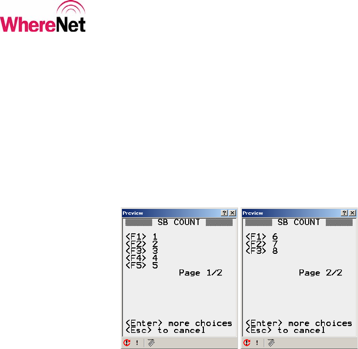
4.2.9 Custom Configuration Number of Sub-blinks
Selecting <I> SB Count from the custom configuration screen 2 will allow the user
to set the number of sub-blinks from 1 to 8 per blink. As soon as the user selects
the number of sub-blinks, the WhereWand application will return to custom
configuration screen 2 to allow another parameter to be selected and modified.
The user can press <Enter> to go between the sub-blink pages, or <ESC> to return
to the previous menu. Figure 20 shows the sub-blink screens.
Figure 20: Custom Config Sub-blinks
Changing the number of sub-blinks will have impacts on both system capacity and
the reliability of the system in locating tags.
____________
Note
____________
___________________________________________________________________________
WhereWand II User’s Guide
___________________________________________________________________________ 34
WhereWand II User’s Guide D1258 rev A
© Copyright WhereNet, Corp. 2002
WhereNet Confidential
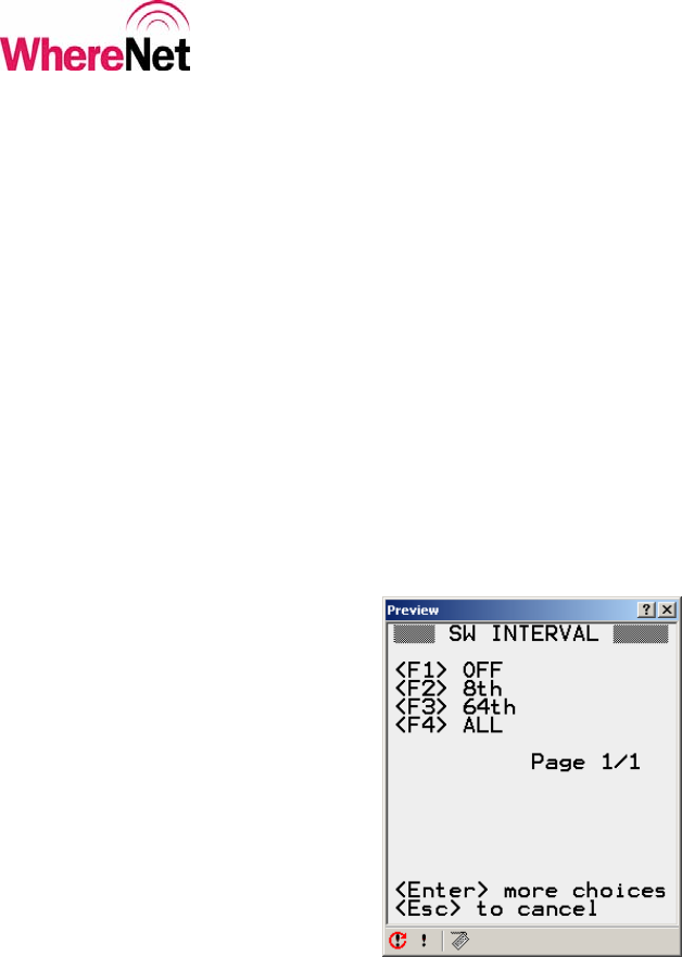
4.2.10 Custom Configuration Long Message Interval
Selecting <J> Long Intrvl from the custom configuration screen 2 will allow the
user to set the tag up to periodically send long message blinks with the 12 byte tag
data register contents appended to the message. This periodic long message can be
disabled by selecting OFF, or it can be set to occur at every 8th or 64th normal keep
alive blink. If ALL is selected, every tag blink including WherePort and switch
event blinks will be long. As soon as the user selects an interval, the WhereWand
application will return to custom configuration screen 2 to allow another parameter
to be selected and modified. The user can press <ESC> to return to the previous
menu. Figure 21 shows the RX wakeup screen.
Figure 21: Custom Config Long Interval
___________________________________________________________________________
WhereWand II User’s Guide
___________________________________________________________________________ 35
WhereWand II User’s Guide D1258 rev A
© Copyright WhereNet, Corp. 2002
WhereNet Confidential
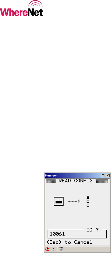
4.3 Read Tag Configuration
When the user selects <F2> Read Config from the Tag Utilities screen, the
WhereWand screen changes to the tag ID entry screen for tag read. The user can
either scan the tag bar code using the WhereWand laser scanner or manually type
the tag ID using WhereWand keypad. The WhereWand will automatically
determine the correct protocol for communicating with the WhereTag or
WhereCall based on the tag’s unique identification on the bar code label. Figure
22 shows the read configuration tag ID entry screen.
WhereTag products with IDs less than 17,100,000 must be separated from other
nearby tags by 18 inches or more when reading the tag to ensure other tags do not
respond and collide with the response of the desired tag.
Figure 22: Tag Read ID Entry
____________
Note
____________
___________________________________________________________________________
WhereWand II User’s Guide
___________________________________________________________________________ 36
WhereWand II User’s Guide D1258 rev A
© Copyright WhereNet, Corp. 2002
WhereNet Confidential
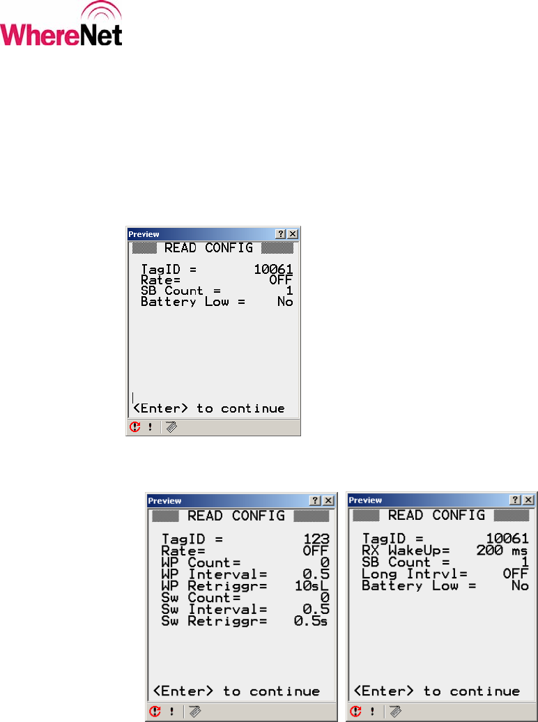
The data displayed will depend on the type of tag being read. The data from a
WhereCall tag is displayed in figure 23. The data from a WhereTag is displayed
in figure 24. Table 1 (at the beginning of section 4.2) details the parameter
meaning.
Figure 23: WhereCall Read Information
Figure 24: WhereTag Read Information
___________________________________________________________________________
WhereWand II User’s Guide
___________________________________________________________________________ 37
WhereWand II User’s Guide D1258 rev A
© Copyright WhereNet, Corp. 2002
WhereNet Confidential
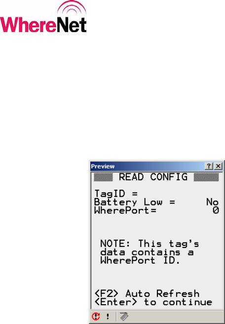
WhereTag II version 2.0 configuration read is through a configuration data mirror.
It is possible for certain WherePort or other information to overwrite this data
mirror. The read configuration will display the information it does read even if it
is not configuration data, as shown in figure 25.
Figure 25: Configuration Data was Overwritten
___________________________________________________________________________
WhereWand II User’s Guide
___________________________________________________________________________ 38
WhereWand II User’s Guide D1258 rev A
© Copyright WhereNet, Corp. 2002
WhereNet Confidential
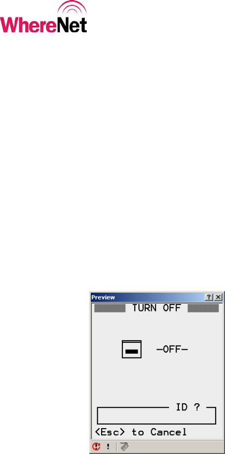
4.4 Turn Tag Off
When the user selects <F3> Read Config from the Tag Utilities screen, the
WhereWand screen changes to the tag ID entry screen for turn off. The user can
either scan the tag bar code using the WhereWand laser scanner or manually type
the tag ID using WhereWand keypad. The WhereWand will automatically
determine the correct protocol for communicating with the WhereTag or
WhereCall based on the tag’s unique identification on the bar code label. The
WhereWand will set the tag blink interval to OFF, and set the number of
WherePort blinks to 0. Figure 26 shows the turn tag off ID entry screen.
Figure 26: Turn Tag Off ID Entry
___________________________________________________________________________
WhereWand II User’s Guide
___________________________________________________________________________ 39
WhereWand II User’s Guide D1258 rev A
© Copyright WhereNet, Corp. 2002
WhereNet Confidential
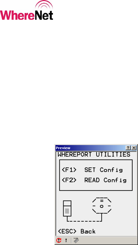
5 WHEREPORT UTILITIES
The user enters the WherePort utilities by press <F2> from the WhereWand
utilities screen shown in figure 3. The WherePort utilities allow the user to set and
read WherePort configuration. Communications with WherePort devices require
the use of the configuration cable included with the WhereWand in the shipping
box. This cable is a standard 10-conductor RJ-45 cable. Figure 27 shows the
WherePort Utilities screen. The magnetic field in the WherePort will be disabled
while connected to the WhereWand via the configuration cable.
Figure 27: WherePort Utilities
5.1 Set WherePort Configuration
To set the WherePort configuration, the user press <F1> from the WherePort
utilities screen. The set WherePort configuration screen is shown in figure 28.
___________________________________________________________________________
WhereWand II User’s Guide
___________________________________________________________________________ 40
WhereWand II User’s Guide D1258 rev A
© Copyright WhereNet, Corp. 2002
WhereNet Confidential
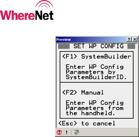
Figure 28: Set WherePort Configuration
5.2 SystemBuilder WherePort Configuration
Selecting <F1> from the set WherePort configuration screen allows to use
predefined configurations. The first step is to complete the site design using
SystemBuilder. One of the outputs of this operation is the file
WherePortLocations.txt. Copy this file to the following directory on the VSS
server:
C:\Program Files\WhereNet\PDT\PDT\PDT Install\link\.
Next use PDT Install to re-install the WhereWand Utilities, as described in section
3.1 and in appendix A. The WherePortLocations.txt file will be installed on the
WhereWand during this operation.
___________________________________________________________________________
WhereWand II User’s Guide
___________________________________________________________________________ 41
WhereWand II User’s Guide D1258 rev A
© Copyright WhereNet, Corp. 2002
WhereNet Confidential
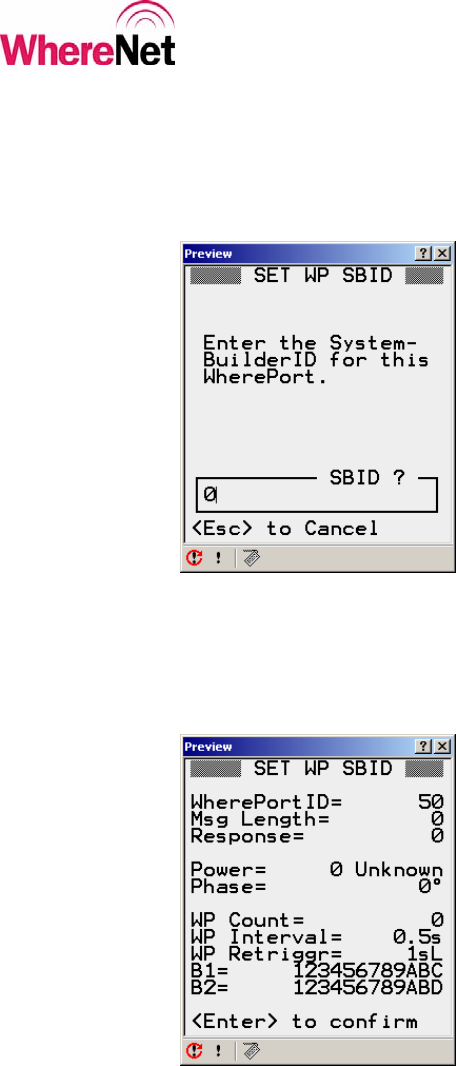
The user will first be prompted to enter in the SystemBuilder WherePort ID (not
the serial number). This ID is set using SystemBuilder. Figure 29 shows the
SystemBuilder WherePort configuration screen
Figure 29: SystemBuilder WherePort Configuration
If the SystemBuilder WherePort ID is found, the configuration information is
displayed for verification, as shown in figure 30.
Figure 30: SB Configuration Confirm
___________________________________________________________________________
WhereWand II User’s Guide
___________________________________________________________________________ 42
WhereWand II User’s Guide D1258 rev A
© Copyright WhereNet, Corp. 2002
WhereNet Confidential
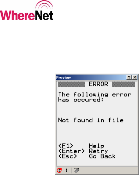
If the SystemBuilder ID was not found in the file, the error message shown in
figure 31 will be displayed.
Figure 31: SB Configuration Error
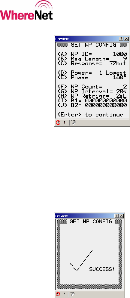
5.3 Manual WherePort Configuration
Selecting <F2> from the set WherePort configuration screen allows the user to
manually select and modify some or all of the WherePort parameters. The
WhereWand will display the screen shown in figure 32.
___________________________________________________________________________
WhereWand II User’s Guide
___________________________________________________________________________ 43
WhereWand II User’s Guide D1258 rev A
© Copyright WhereNet, Corp. 2002
WhereNet Confidential
Figure 32: Manual WherePort Configuration
When the user press <Enter> from this screen, the WhereWand will send the
WherePort configuration via the cable. It will read back the configuration to
verify the communication was successful, and if so it will the show the screen in
figure 33.
Figure 33: WherePort Configuration Success
___________________________________________________________________________
WhereWand II User’s Guide
___________________________________________________________________________ 44
WhereWand II User’s Guide D1258 rev A
© Copyright WhereNet, Corp. 2002
WhereNet Confidential
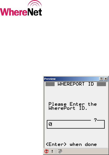
5.3.1 Configure WherePort ID
Selecting <A> WP ID from the set WP config screen allows the user to set the
WherePort ID. Any ID from 256 to 32,767 can be used, but it is important to keep
from repeating the ID of nearby WherePorts to avoid retrigger issues. Figure 34
shows the WherePort ID screen.
Figure 34: WherePort ID
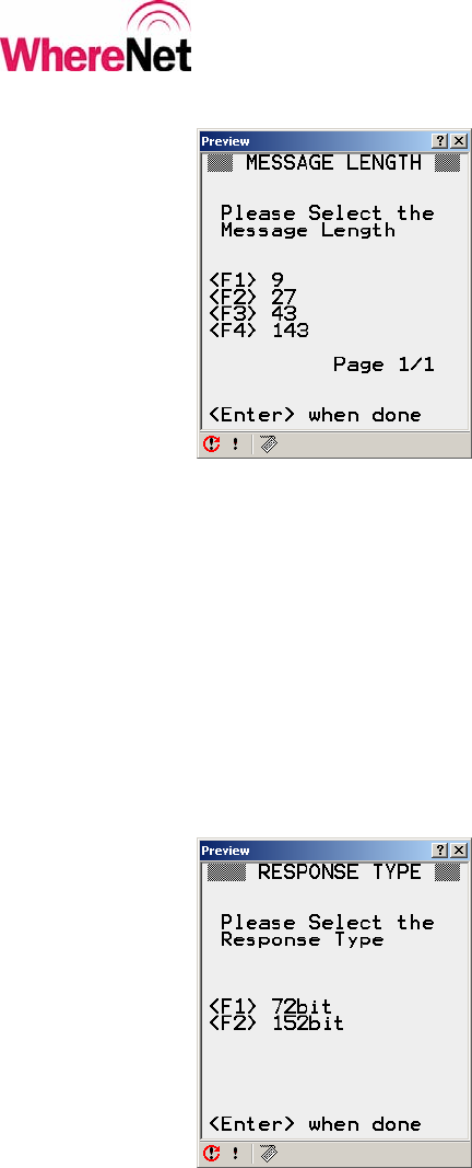
5.3.2 Configure WherePort Message Length
Selecting <B> from the set WherePort configuration screen allows the user to set
the message length, which defines the message type. There are 4 different
message lengths supported. The message length defines which of the other
WherePort configuration parameters are applicable. Table 3 outlines the
applicable parameters versus the message length.

___________________________________________________________________________
WhereWand II User’s Guide
___________________________________________________________________________ 45
WhereWand II User’s Guide D1258 rev A
© Copyright WhereNet, Corp. 2002
WhereNet Confidential
Table 2: WherePort Message Parameters
WherePort Message Length
Parameter Message
Length 9 Message
Length 27 Message
Length 43 Message
Length 143
WherePort ID 8 - 15 0 - 32,767 0 - 32,767
Tag Response 1: 72-bit blinks
3: 152-bit blinks 1: 72-bit blinks
3: 152-bit blinks
Power 1 - 8 1 - 8 1 - 8 1 - 8
Phase 0°, 90°,
180°, 270° 0°, 90°, 180°,
270° 0°, 90°, 180°,
270° 0°, 90°, 180°,
270°
WP Count 0 - 15
WP Interval 5 sec - 1 min
WP Retrigger 1 sec - 2 min,
3 modes
Buffer 1 12 hexadecimal
characters
Buffer 2 12 hexadecimal
characters
<F1> or length 9 is the legacy mode compatible with some early installations and
only supports a WherePort ID between 8 and 15. The tag will send normal 56-bit
messages with the WherePort ID embedded in the 4-bit status. This message will
work with WhereTag II V2.0 and WhereTag II V2.1.

___________________________________________________________________________
WhereWand II User’s Guide
___________________________________________________________________________ 46
WhereWand II User’s Guide D1258 rev A
© Copyright WhereNet, Corp. 2002
WhereNet Confidential
Most applications will use <F2> or length 27. This will support any WherePort ID
between 0 and 32,767. The message also includes the tag response information to
select between 72-bit or 152-bit tag blink response. The 15-bit WherePort ID is
added to the normal tag blink. The tag’s 4-bit status will always be 1000. This
message only works with WhereTag V2.1 tags.
<F3> or length 43 will support any WherePort ID between 0 and 32,767. The
message also includes the tag response information to select between a 72-bit or
152-bit tag blink response. The 15-bit WherePort ID is added to the normal tag
blink. The tag’s 4-bit status will always be 1000. This message also includes
limited tag configuration parameters. The parameters include:
Number of WherePort Blinks (0 through 15)
WherePort Blink Interval (5 seconds to 1 minute)
WherePort Retrigger (1 second to 2 minutes, three modes)
These parameters will permanently overwrite the existing tag configuration. This
message only works with WhereTag V2.1 tags.
<F4> or length 143 is used to send the tag 12 bytes of data. The data is the entire
WherePort message, so there is no associated WherePort ID in the tag blinks. This
message only works with WhereTag V2.1 tags.
Figure 35 shows the message length screen.
___________________________________________________________________________
WhereWand II User’s Guide
___________________________________________________________________________ 47
WhereWand II User’s Guide D1258 rev A
© Copyright WhereNet, Corp. 2002
WhereNet Confidential
Figure 35: WherePort Message Length
5.3.3 Configure WherePort Tag Response
Selecting <C> from the set WherePort configuration screen allows the user to set
how the tag will respond to the WherePort message. This is only applicable to
message lengths of 27 and 43. The options are to have the tag send 72-bit blinks
or 152-bit blinks. Both will contain the 15-bit WherePort ID. Figure 36 shows the
tag response screen.
Figure 36: WherePort Tag Response
___________________________________________________________________________
WhereWand II User’s Guide
___________________________________________________________________________ 48
WhereWand II User’s Guide D1258 rev A
© Copyright WhereNet, Corp. 2002
WhereNet Confidential
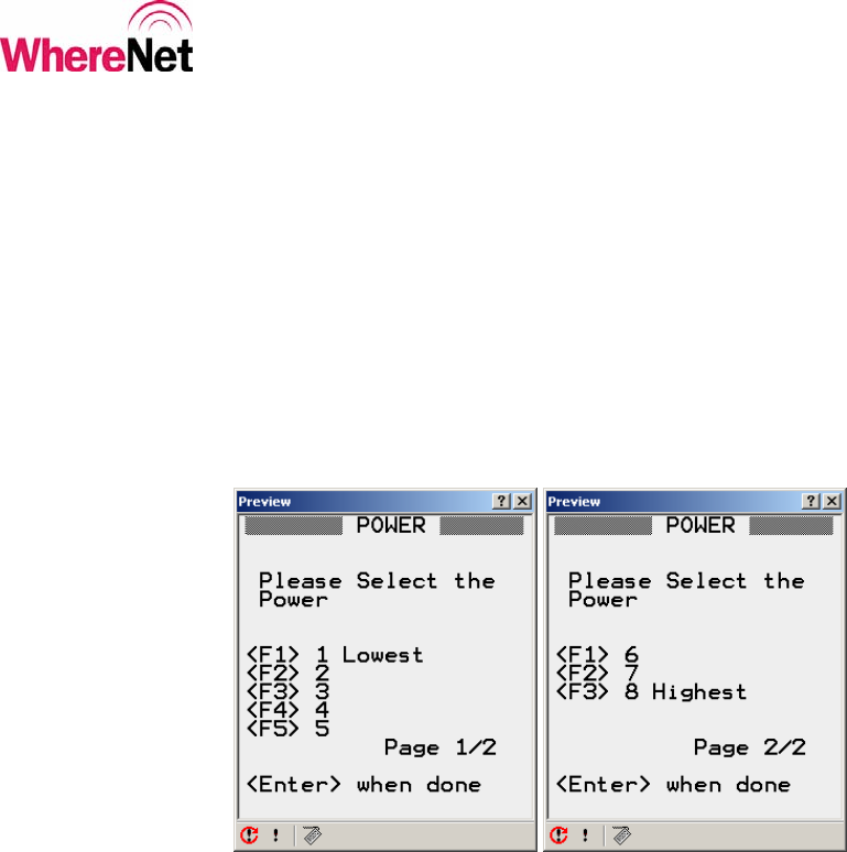
5.3.4 Configure WherePort Power
Selecting <D> from the set WherePort configuration screen allows the user to
select from one of eight power levels. The maximum power setting 8 will give
about a 20 foot range. The minimum power setting 1 will give about a 3 foot
range. Care should be taken when setting the power to avoid under covering an
area, or over covering an area and having the signal bleed into undesired areas.
Figure 37 shows the WherePort power screens.
Figure 37: WherePort Power
Table 3 outlines the WherePort to Tag range for the power levels. Since the range
is dependent on the tag orientation in the WherePort field, the table defines 3
zones. The green zone is the range at which the tag will always see the
WherePort, regardless of orientation, as it passes through the zone. The yellow
zone will typically work, but the tag may not receive the WherePort message if it
is oriented poorly in relation to the field. The red zone is an area that the tag will

___________________________________________________________________________
WhereWand II User’s Guide
___________________________________________________________________________ 49
WhereWand II User’s Guide D1258 rev A
© Copyright WhereNet, Corp. 2002
WhereNet Confidential
not likely, but still may receive the WherePort message. The WherePort field does
reach to the red zone and can cause interference with other WherePorts.
Table 3: WherePort Power vs. Range
Power Green Zone (ft) Yellow Zone (ft) Red Zone (ft)
8 0 - 14 14 - 21 21 - 30
7 0 - 12 12 - 17 17 - 24
6 0 - 8 8 - 11 11 - 17
5 0 - 7 7 - 10 10 - 15
4 0 - 6 6 - 9 9 - 13
3 0 - 5 5 - 8 8 - 11
2 0 - 4 4 - 6 6 - 9
1 0 - 3 3 - 5 5 - 6
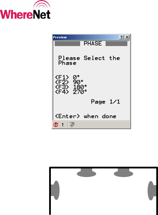
5.3.5 Configure WherePort Phase
Selecting <E> from the set WherePort configuration screen allows the user to set
the phase of WherePorts when multiple WherePorts are connected to provide a
larger area of coverage.
The phase of a single WherePort should always be set to 0°.
When multiple WherePorts are connected, the first WherePort in the chain should
always be set to 0°. WherePorts facing the same direction should have the same
phase, and every 90°change in the mounting direction should correspond to a 90°
phase change. Figure 38 shows the WherePort phase setting screen. Figure 39
shows an example of the phase setting in a typical multi-WherePort installation.
___________________________________________________________________________
WhereWand II User’s Guide
___________________________________________________________________________ 50
WhereWand II User’s Guide D1258 rev A
© Copyright WhereNet, Corp. 2002
WhereNet Confidential
Figure 38: WherePort Phase
Figure 39: Multi-WherePort Phase Example
5.3.6 Configure WherePort Tag Parameters
Options <F> <G> or <H> apply only to WherePort message length 43. These
parameters allow the user to set the tag’s WherePort response configuration
parameters. This allows the user to globally change the way tags respond to
WherePorts without configuring each tag. Any tag that passes within the field of a
0°
90°
180°
90°

___________________________________________________________________________
WhereWand II User’s Guide
___________________________________________________________________________ 51
WhereWand II User’s Guide D1258 rev A
© Copyright WhereNet, Corp. 2002
WhereNet Confidential
WherePort sending these messages will respond using the new parameters
included in the WherePort message. Since these parameters are written to the tag
configuration, they are identical to the parameters described in the tag utilities
section of this document.
CAUTION: These changes are permanent and will affect the way the tag will
respond to all WherePorts until the tag is re-configured with either the
WhereWand or another configuring WherePort.
The WherePort Blink Count is described in section 4.2.2. The WherePort Blink
interval is described in section 4.2.3. The WherePort Retrigger is described in
section 4.2.4. The screens are also shown in section 4.2, figures 12 through 14.
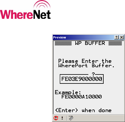
5.3.7 Configure WherePort Data Buffer
Selecting <I> or <J> from the set WherePort configuration screen allows the user
to enter the data sent in WherePort message length 143. The buffer is 12-bytes
long and is broken into 2 parts for display purposes. The data is entered in
hexadecimal (12 characters per half). Figure 40 shows the screen for entering
buffer data.
___________________________________________________________________________
WhereWand II User’s Guide
___________________________________________________________________________ 52
WhereWand II User’s Guide D1258 rev A
© Copyright WhereNet, Corp. 2002
WhereNet Confidential
Figure 40: WherePort Buffer
When the user presses <Enter> from the set WherePort configuration screen, the
WhereWand will send the WherePort configuration via the cable. It will read back
the configuration to verify the communication was successful, and if so it will
show the success screen in figure 34.
___________________________________________________________________________
WhereWand II User’s Guide
___________________________________________________________________________ 53
WhereWand II User’s Guide D1258 rev A
© Copyright WhereNet, Corp. 2002
WhereNet Confidential
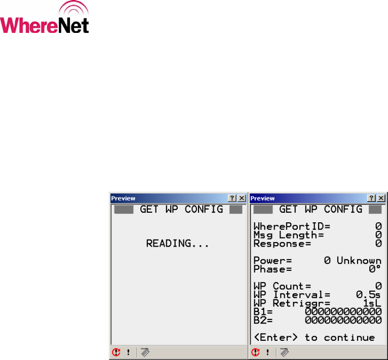
5.4 Read WherePort Configuration
When the user selects <F2> from the WherePort utilities screen, the WhereWand
will read and display the WherePort configuration. The cable must be connected
between the WhereWand and the WherePort. Figure 41 shows the read WherePort
configuration screens.
Figure 41: Read WherePort Configuration
6 LOCATION SENSOR UTILITIES
The user enters the WherePort utilities by press <F3> from the WhereWand
utilities screen shown in figure 3. The Location Sensor utilities allow the user to
Perform link check by flashing the LEDs on the Location Sensor
Reconfigure the Location Sensor network parameters
Re-boot the Location Sensor.

___________________________________________________________________________
WhereWand II User’s Guide
___________________________________________________________________________ 54
WhereWand II User’s Guide D1258 rev A
© Copyright WhereNet, Corp. 2002
WhereNet Confidential
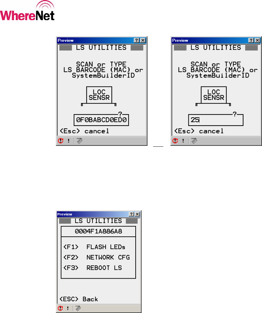
The WhereWand communicates with the Location Sensor by sending DSSS blinks
containing the MAC address of the Location Sensor. The first screen the user sees
is a prompt for the Location Sensor’s MAC address. This can be manually typed in
using the WhereWand keypad, or scan from the Location Sensor bar code label
using the WhereWand laser scanner. The bar code label is located on the back of
the Location Sensor and in the site design document. Figure 42 shows the MAC
address entry screen.
Important: If the MAC does not start with 0004F1, all LS operations will result
in an error. This is a safety feature to prevent unnecessary transmissions from the
WhereWand.
Alternately, the user can enter the System Builder ID for that Location Sensor.
This will access the file LocationSensors.txt on the WhereWand to get the MAC
address.
Important: The LocationSensors.txt file should be in directory C:\Program
Files\WhereNet\PDT\PDTInstall\link directory prior to running PDT install.
Important: This LS configuration operations consume a significant part of the
System RF capacity.
___________________________________________________________________________
WhereWand II User’s Guide
___________________________________________________________________________ 55
WhereWand II User’s Guide D1258 rev A
© Copyright WhereNet, Corp. 2002
WhereNet Confidential
OR
Figure 42: Location Sensor MAC Address or System Builder ID for that LS.
After entering the Location Sensor MAC address, the utilities screen shown in
figure 43 is displayed.
Figure 43: Location Sensor Utilities
___________________________________________________________________________
WhereWand II User’s Guide
___________________________________________________________________________ 56
WhereWand II User’s Guide D1258 rev A
© Copyright WhereNet, Corp. 2002
WhereNet Confidential
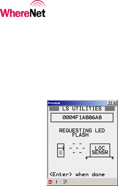
6.1 Flashing Location Sensor LEDs
Pressing <F1> will cause the WhereWand to transmit the messages to flash the
Location Sensor LEDs. This is useful in verifying that the user is communicating
with the correct Location Sensor and that the link is functional. The WhereWand
will automatically stop after 30 seconds, or the user can press <Enter> to stop the
test at any time. Figure 44 shows the LED flash screen.
Figure 44: Location Sensor LED Flash
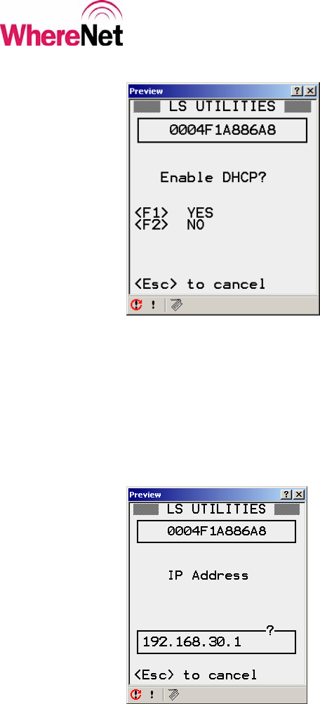
6.2 Configuring the Location Sensor Network Properties
Pressing <F2> will allow the user to set the network properties of the Location
Sensor. First the user can select to enable or disable DHCP, as shown in figure 45.
___________________________________________________________________________
WhereWand II User’s Guide
___________________________________________________________________________ 57
WhereWand II User’s Guide D1258 rev A
© Copyright WhereNet, Corp. 2002
WhereNet Confidential
Figure 45: Location Sensor DHCP
If the user selected NO on the enable DHCP screen, the user will be prompted for
the IP address, as shown in figure 46. This screen is skipped if the user selected
YES to enable the DHCP.
Figure 46: Location Sensor IP Address
___________________________________________________________________________
WhereWand II User’s Guide
___________________________________________________________________________ 58
WhereWand II User’s Guide D1258 rev A
© Copyright WhereNet, Corp. 2002
WhereNet Confidential
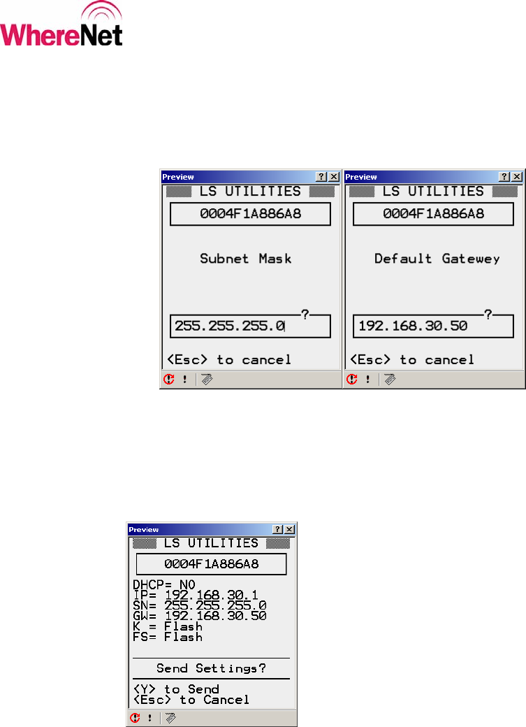
The user is next prompted for the subnet mask and the default gateway as shown
in figure 47. If the gateway is left blink and the user hits enter, the gateway
defaults to 0.0.0.0.
Figure 47: Location Sensor Subnet Mask and Gateway
The Location Sensor network properties are then displayed for confirmation by the
user, as shown in figure 48.
Figure 48: Location Sensor Network Properties
___________________________________________________________________________
WhereWand II User’s Guide
___________________________________________________________________________ 59
WhereWand II User’s Guide D1258 rev A
© Copyright WhereNet, Corp. 2002
WhereNet Confidential
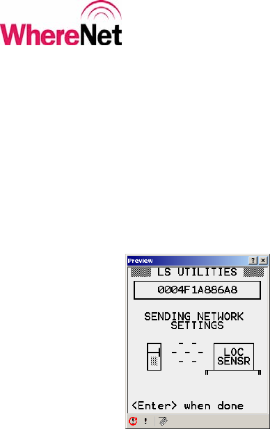
The user can press <Y> to send the properties to the Location Sensor or hit <Esc>
to cancel and change the settings again. It takes 10 seconds to transmit all the
properties from the WhereWand to the Location Sensor. The screen show in
figure 49 is displayed while the WhereWand is sending the properties. The LED
on the Location Sensor will flash on and off at a 1 second rate if the link is
functional and the command is being received correctly.
Figure 49: Location Sensor Sending
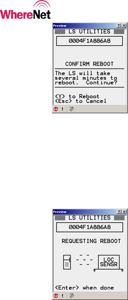
6.3 Rebooting the Location Sensor
Rebooting the Location Sensor will take it out of commission until it completes
the reboot. This can take several minutes so a confirmation screen is presented as
shown in figure 50.
Important: The reboot message will be transmitted for 15 seconds. Pressing a
key will stop the transmission.
___________________________________________________________________________
WhereWand II User’s Guide
___________________________________________________________________________ 60
WhereWand II User’s Guide D1258 rev A
© Copyright WhereNet, Corp. 2002
WhereNet Confidential
Figure 50: Location Sensor Confirm Reboot
The user can press <Y> to proceed and re-boot the Location Sensor, or hit <Esc>
to cancel the operation. It takes 15 seconds to send the reboot sequence from the
WhereWand to the Location Sensor. The LED on the Location Sensor will flash
on and off at a 1 second rate if the link is functional and the command is being
received correctly. Press any key during this time will stop the transmission.
During this time, the screen shown in figure 51 is displayed.
Figure 51: Location Sensor Rebooting

___________________________________________________________________________
WhereWand II User’s Guide
___________________________________________________________________________ 61
WhereWand II User’s Guide D1258 rev A
© Copyright WhereNet, Corp. 2002
WhereNet Confidential
7 LOGGING
Reading or writing to hardware via the WhereWand Utilities is logged. The log
file contains the timestamp of the event, the operation performed, and the
configuration parameters used. The file is saved on the WhereWand in
C:\WhereNet\Log.txt. Below is a sample log file:
02/14/1980 05:11:40,TAG SET,TE_SUCCESS,0016777405,0,2,10,3,3,4,0,0,0,0,0,0,4,1,5,1,1,0,0,0
02/14/1980 05:11:49,TAG READ,TE_SUCCESS,0016777405,0,2,10,3,3,4,0,1,0,0,0,0,4,1,5,2,1,0,0,0
02/14/1980 07:31:06,LS FLASH LEDS,TE_SUCCESS,0004F1A886A8
02/14/1980 07:31:26,LS REBOOT,TE_SUCCESS,0004F1A886A8
02/14/1980 07:31:30,LS FLASH LEDS,TE_SUCCESS,0004F1A886A8
02/14/1980 08:12:05,LS REBOOT,TE_SUCCESS,0004F1A886A8,,255.255.255.0,192.0.0.0,1,1,1
02/14/1980 08:15:12,LS REBOOT,TE_SUCCESS,0004F1A886A8,90.0.0.0,255.255.255.0,192.0.0.0,1,1,1
02/14/1980 08:22:26,LS REBOOT,TE_SUCCESS,0004F1A886A8,,255.255.255.0,1.1.1.1,1,F,F
All read and write operations to WhereTag/WhereCall, WherePort, or Location
Sensors will be logged.
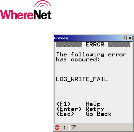
7.1 Log File Disk Usage
The log file consumes approximately 80 bytes per record. The WhereWand
typically starts with about 800K free disk space. This means that after about 1000
operations the log file must be transferred to another computer and deleted from
the WhereWand. If you get a message like the one shown in figure 52, the disk is
probably full:
___________________________________________________________________________
WhereWand II User’s Guide
___________________________________________________________________________ 62
WhereWand II User’s Guide D1258 rev A
© Copyright WhereNet, Corp. 2002
WhereNet Confidential
Figure 52: Log Write Error
Important: About every 1000 operations the log file should be transferred to
another computer. Otherwise the drive will fill and no further logging will take
place.
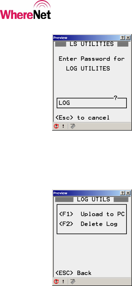
Logging utilities are entered from the main utilities screen (figure 3) by pressing
<F5>. The user will be prompted for the password, which is LOG. The password
screen is shown in figure 53.
___________________________________________________________________________
WhereWand II User’s Guide
___________________________________________________________________________ 63
WhereWand II User’s Guide D1258 rev A
© Copyright WhereNet, Corp. 2002
WhereNet Confidential
Figure 53: Log Utilities Password
The user types in LOG and hits <Enter> to get to the Log Utilities screen shown in
figure 54. The available options are to upload the log file to a computer, or delete
the log file.
Figure 54: Log Utilities
___________________________________________________________________________
WhereWand II User’s Guide
___________________________________________________________________________ 64
WhereWand II User’s Guide D1258 rev A
© Copyright WhereNet, Corp. 2002
WhereNet Confidential
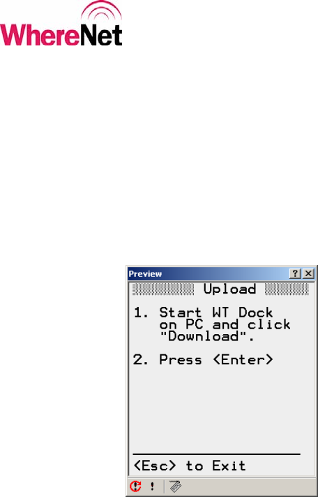
7.2 Uploading the Log File
Press <F1> from the log utilities screen to upload the file. To upload the log file,
the user must put the WhereWand in the battery charging dock and connect the
serial cable from the dock to the computer’s serial port. Figure 55 shows the
WhereWand upload log file screen.
Figure 55: Log File Upload
The log file is uploaded using the WhereTools Dock program which is run on a
laptop or desktop computer. It can be launched through the windows start menu
by:
At Windows desktop, click Start >>
Programs >>
WhereNet Visibility Server Software >>
WhereTools >>
Dock.
___________________________________________________________________________
WhereWand II User’s Guide
___________________________________________________________________________ 65
WhereWand II User’s Guide D1258 rev A
© Copyright WhereNet, Corp. 2002
WhereNet Confidential
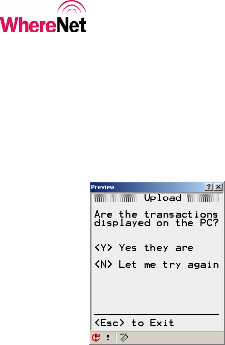
Press <Enter> on the WhereWand and then click the Download button on the
computer screen. Activity will show on both screens. When the upload is
complete, the log file will be displayed in the window on the computer screen.
The WhereWand will ask the user to confirm that the log file is displayed on the
computer with the screen shown in figure 56. Appendix B shows the computer
screen for WhereTools Dock.
Figure 56: Log File Confirmation
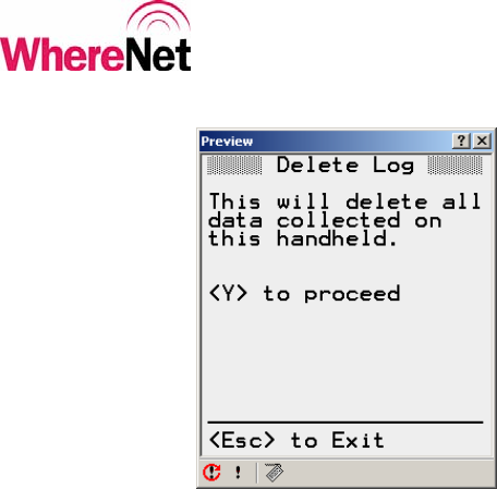
7.3 Deleting the Log File
Pressing <F2> from the log utilities screen will allow the user to delete the log file
from the WhereWand memory. The user will be prompted be sure the log file
should be deleted. The user can hit <Y> to delete the file or <Esc> to cancel the
operation. Figure 57 shows the confirm delete screen.
Important: Deleting the log without first downloading it to the host computer will
result in the loss of the log data.
___________________________________________________________________________
WhereWand II User’s Guide
___________________________________________________________________________ 66
WhereWand II User’s Guide D1258 rev A
© Copyright WhereNet, Corp. 2002
WhereNet Confidential
Figure 57: Delete Log File
8 WHEREWAND ADAPTER SPECIFICATION
8.1 Mechanical
Operating Temperature 0 to +55°C
Storage Temperature -20 to +85°C
Humidity 95% non condensing
Dimensions 4.2 x 2.5 x 1.0 inches
Weight 135 oz

___________________________________________________________________________
WhereWand II User’s Guide
___________________________________________________________________________ 67
WhereWand II User’s Guide D1258 rev A
© Copyright WhereNet, Corp. 2002
WhereNet Confidential
8.2 DSSS RF Transmit Performance
Frequency 2441.75 MHz
Spreading 511 chips/bit
Chip Rate 30.52 MHz
Data Rate 59.73 kbit/sec
Power <1 mW
Range (to Location Sensor) up to 200 feet
8.3 OOK/FSK Transmit/Receive Performance
Frequency 2441.75 MHz
OOK/FSK Rates 375 kHz / 535 kHz
Power <1 mW
Data Rate 19.83 kbit/sec
Range (to/from Tag) 0 to 6 feet
8.4 Magnetic FSK Transmit Performance
FSK Frequencies 114.7 kHz / 127.0 kHz
Power <1 mA/meter
Data Rate 2.048 kbit/sec
Range (to Tag) 0 to 12 inches

___________________________________________________________________________
WhereWand II User’s Guide
___________________________________________________________________________ 68
WhereWand II User’s Guide D1258 rev A
© Copyright WhereNet, Corp. 2002
WhereNet Confidential
8.5 Wired WherePort Link Performance
Cable Length 10 feet
Data Rate 1.0 kbit/sec
8.6 Bar Code Scanner Performance
Code Code39 or Code128
Range (to Tag or Location Sensor) 2 to 12 inches
___________________________________________________________________________
WhereWand II User’s Guide
___________________________________________________________________________ 69
WhereWand II User’s Guide D1258 rev A
© Copyright WhereNet, Corp. 2002
WhereNet Confidential
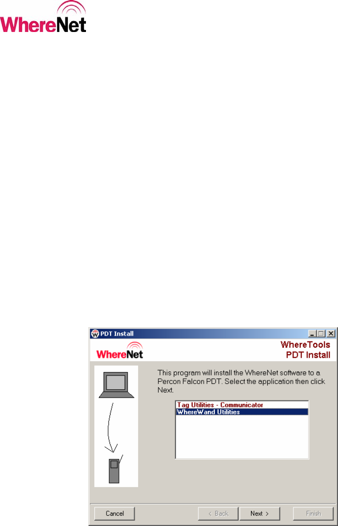
A PDT INSTALL SCREENS
This appendix describes the PDT Install program operation. This program should
be done to reload the WhereWand software, download SystemBuilder WherePort
configuration files, or the download software upgrades to the WhereWand. This
program is run on a desktop or laptop computer. The computer serial port COM1
should be connected to the WhereWand battery charging dock with the serial cable
included in the WhereWand shipping box. This program is launched through the
Windows start menu by clicking:
Start >>
Programs >>
WhereNet Visibility Server Software >>
WhereTools >>
PDT Install
The first screen is shown figure 58.
Figure 58: PDT Install Screen
___________________________________________________________________________
WhereWand II User’s Guide
___________________________________________________________________________ 70
WhereWand II User’s Guide D1258 rev A
© Copyright WhereNet, Corp. 2002
WhereNet Confidential
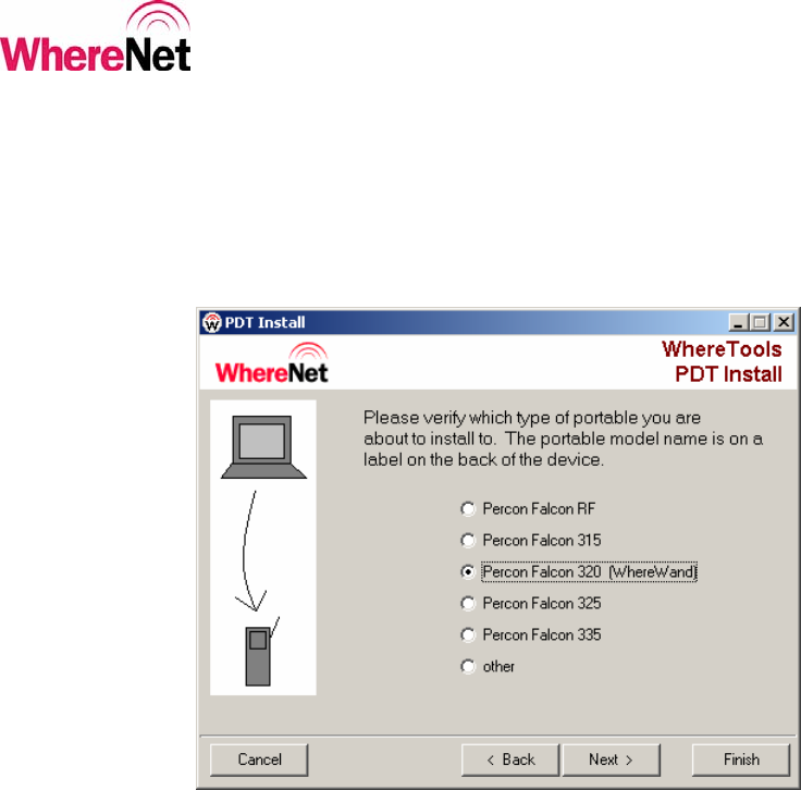
The user should select WhereWand Utilities and the click <Next>. The next
screen allows the user to select the WhereWand platform. This should typically be
the Percon Falcon 320 (WhereWand). The screen is shown in figure 59.
Figure 59: PDT Install Platform
___________________________________________________________________________
WhereWand II User’s Guide
___________________________________________________________________________ 71
WhereWand II User’s Guide D1258 rev A
© Copyright WhereNet, Corp. 2002
WhereNet Confidential
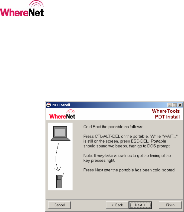
The user should select Percon Falcon 320 (WhereWand) and then click <Next>.
The next screen will direct the user to cold-boot the WhereWand. This is done by
pressing <CTL><ALT><DEL> simultaneously on the WhereWand. When the
WhereWand display shows “WAIT”, the user should press <ESC><DEL>
simultaneously. This happens quickly, so it is suggested that the user locate all
these keys and be ready to press them before starting this step. The directions are
shown in figure 60.
Figure 60: PDT Install WW Boot
___________________________________________________________________________
WhereWand II User’s Guide
___________________________________________________________________________ 72
WhereWand II User’s Guide D1258 rev A
© Copyright WhereNet, Corp. 2002
WhereNet Confidential
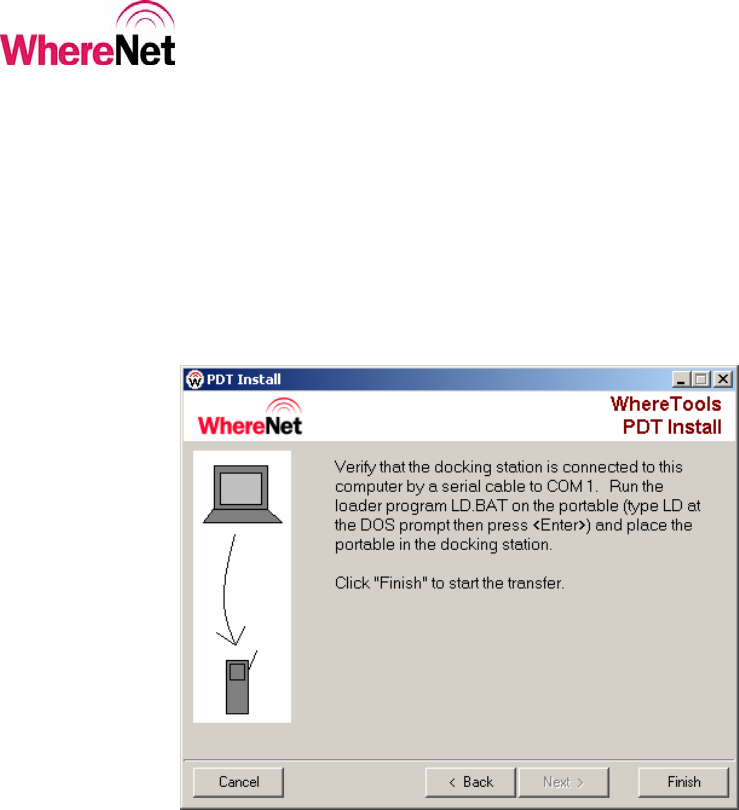
After successfully cold-booting the WhereWand, the user should click <Next>.
The next screen will direct the user to launch the file transfer program on the
WhereWand and place the WhereWand in the battery charging dock. The user
should type “LD” and the <Enter> at the DOS prompt on the WhereWand. Then
the user should place the WhereWand in the dock, and then click <Finish> on the
screen. Figure 61 shows the instructions.
Figure 61: PDT Install WW Launch
___________________________________________________________________________
WhereWand II User’s Guide
___________________________________________________________________________ 73
WhereWand II User’s Guide D1258 rev A
© Copyright WhereNet, Corp. 2002
WhereNet Confidential
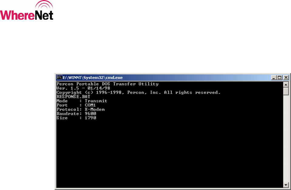
After the user has launched the file transfer program on the WhereWand and
clicked <Finish>, the transfer will begin. The screen shown in figure 62 will
display the file transfer status.
Figure 62: PDT Install Transferring
___________________________________________________________________________
WhereWand II User’s Guide
___________________________________________________________________________ 74
WhereWand II User’s Guide D1258 rev A
© Copyright WhereNet, Corp. 2002
WhereNet Confidential
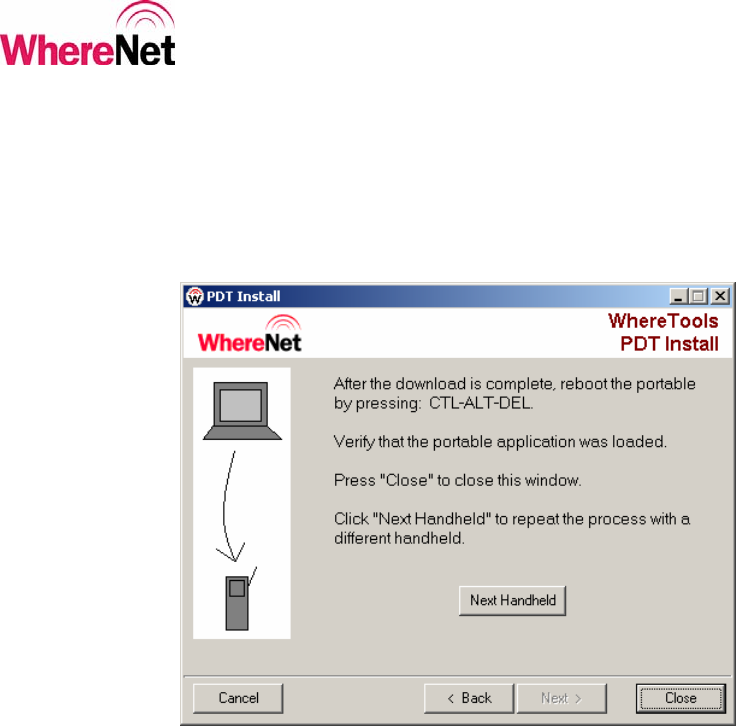
After the last file has been downloaded to the WhereWand, the screen shown in
figure 66 will be displayed. The user is instructed to re-boot the WhereWand and
then either close PDT Install or download the software to another WhereWand.
Figure 63 shows the screen.
Figure 63: PDT Install Complete
___________________________________________________________________________
WhereWand II User’s Guide
___________________________________________________________________________ 75
WhereWand II User’s Guide D1258 rev A
© Copyright WhereNet, Corp. 2002
WhereNet Confidential
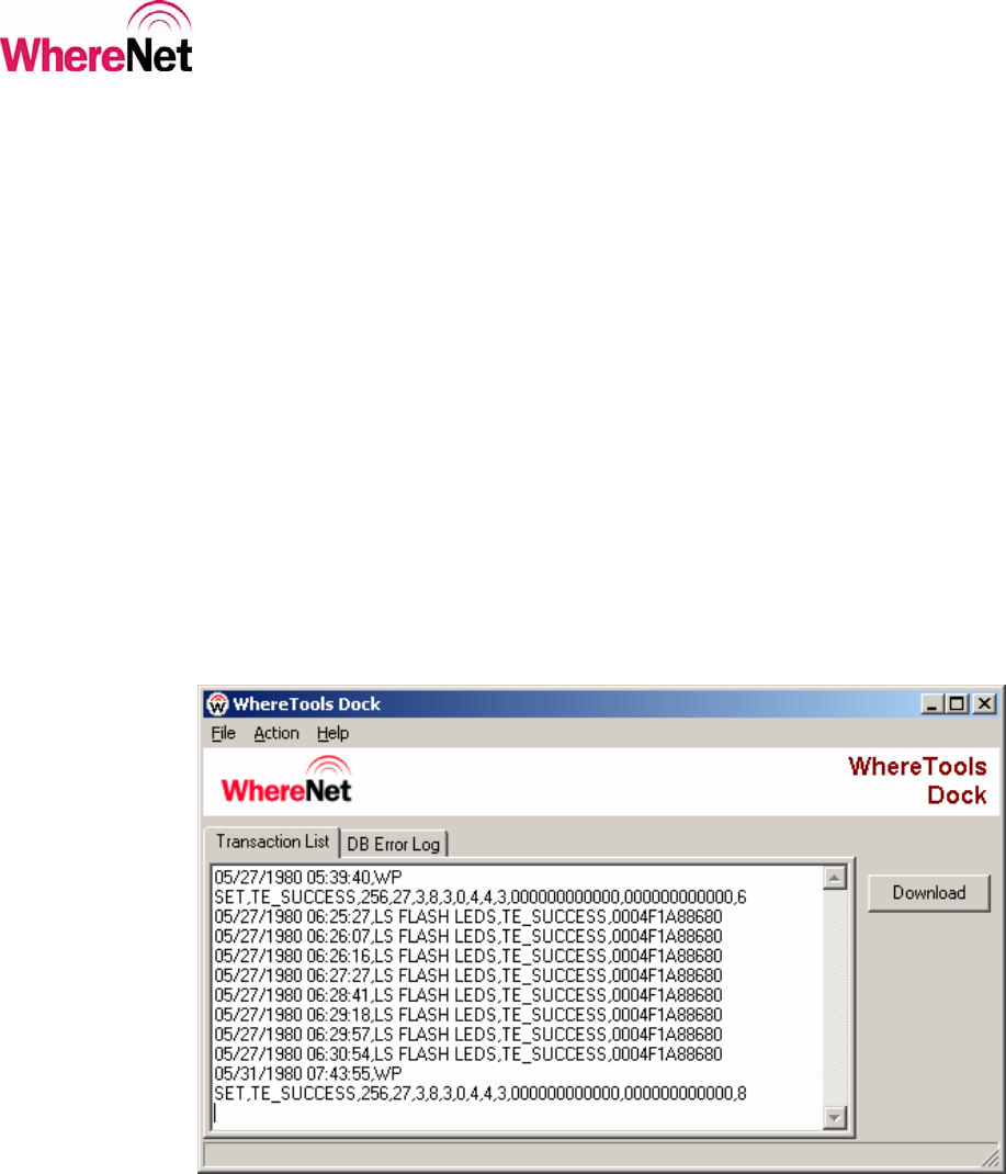
B LOG DOCK SCREEN
This appendix describes the WhereTools Dock program operation. This program
is run to upload the log file from the WhereWand to a desktop or laptop computer.
This program is run on a desktop or laptop computer. The computer serial port
COM1 should be connected to the WhereWand battery charging dock with the
serial cable included in the WhereWand shipping box. This program is launched
through the Windows start menu by clicking:
Start >>
Programs >>
WhereNet Visibility Server Software >>
WhereTools >>
Dock
The WhereTools Dock screen is shown in figure 64.
Figure 64: WhereTools Dock Screen