Zebra Technologies WPT-3400 WherePort IV User Manual D1300rA 81208 ClassA
Zebra Technologies Corporation WherePort IV D1300rA 81208 ClassA
UserManual.wiki
>
Zebra Technologies
>
WPT 3400 User Manual
Users Manual
Navigation menu
Upload a User Manual
Namespaces
Wiki Guide
HTML
PDF
Info
Views
User Manual
Discussion / Help
Navigation
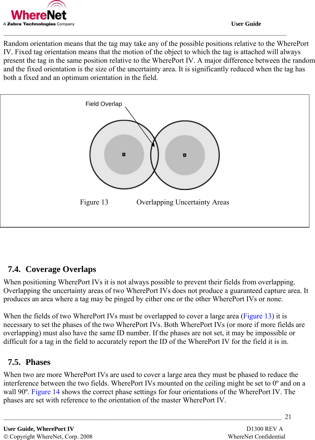
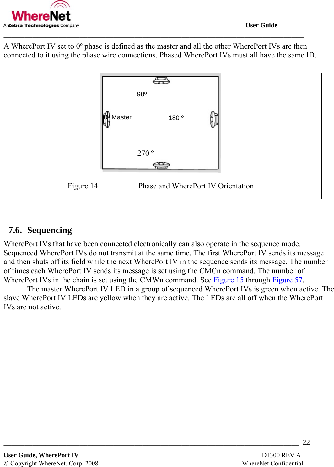
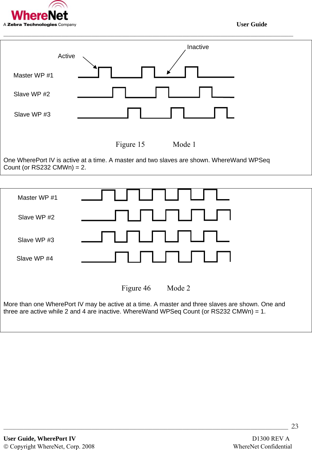
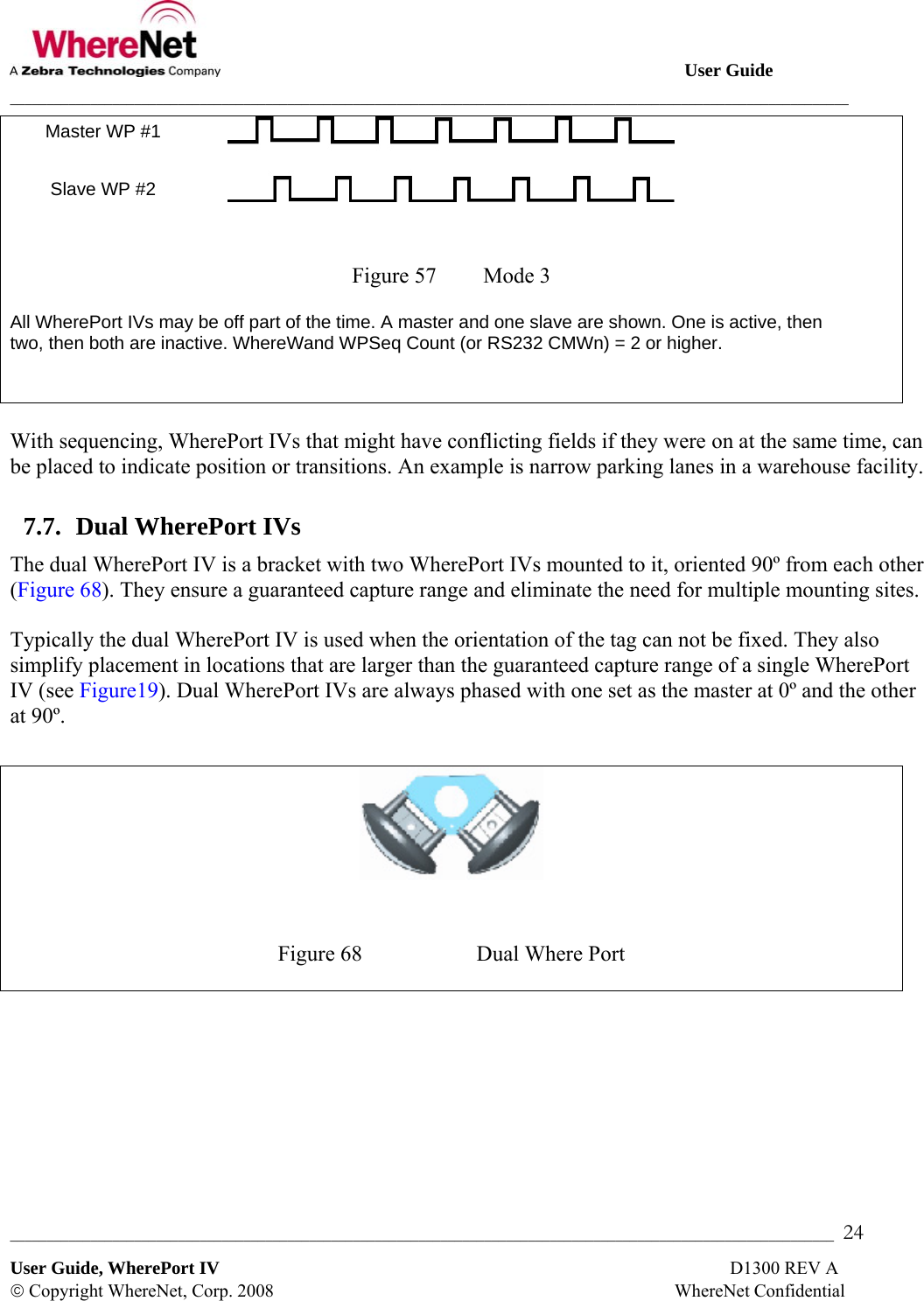

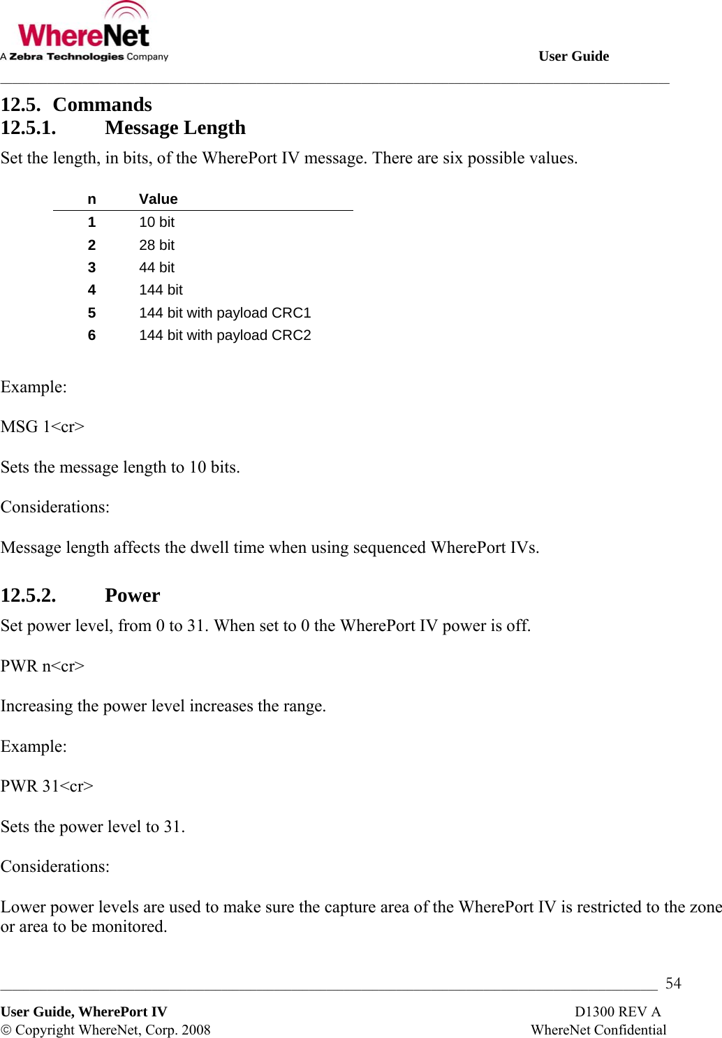
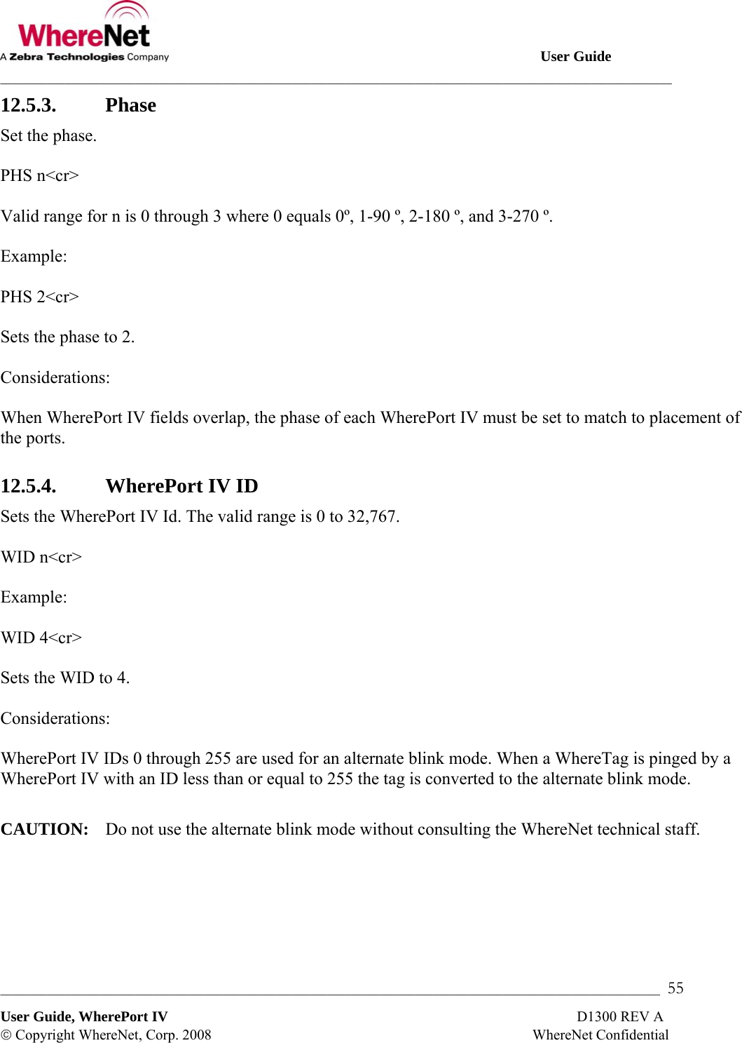
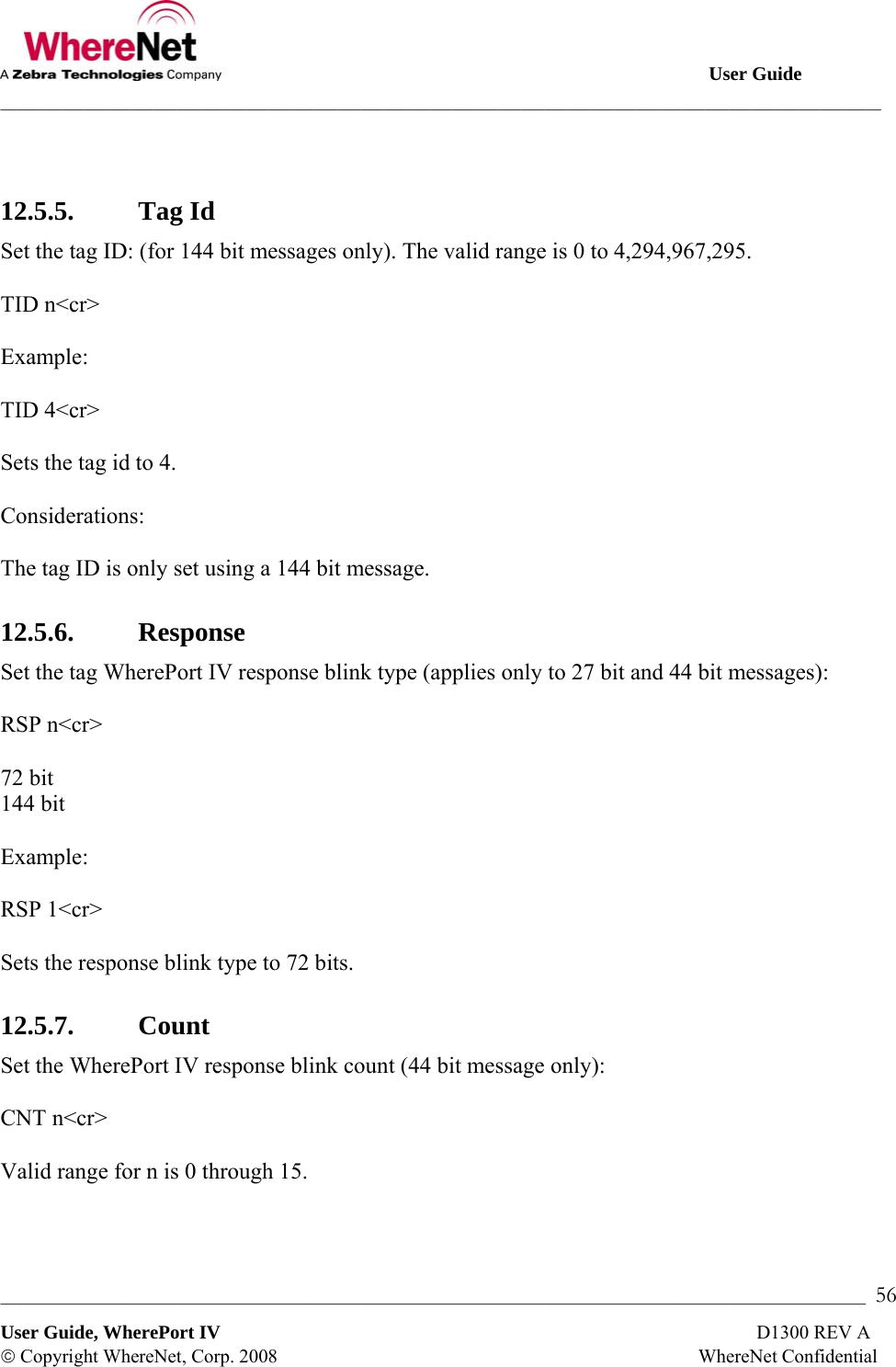
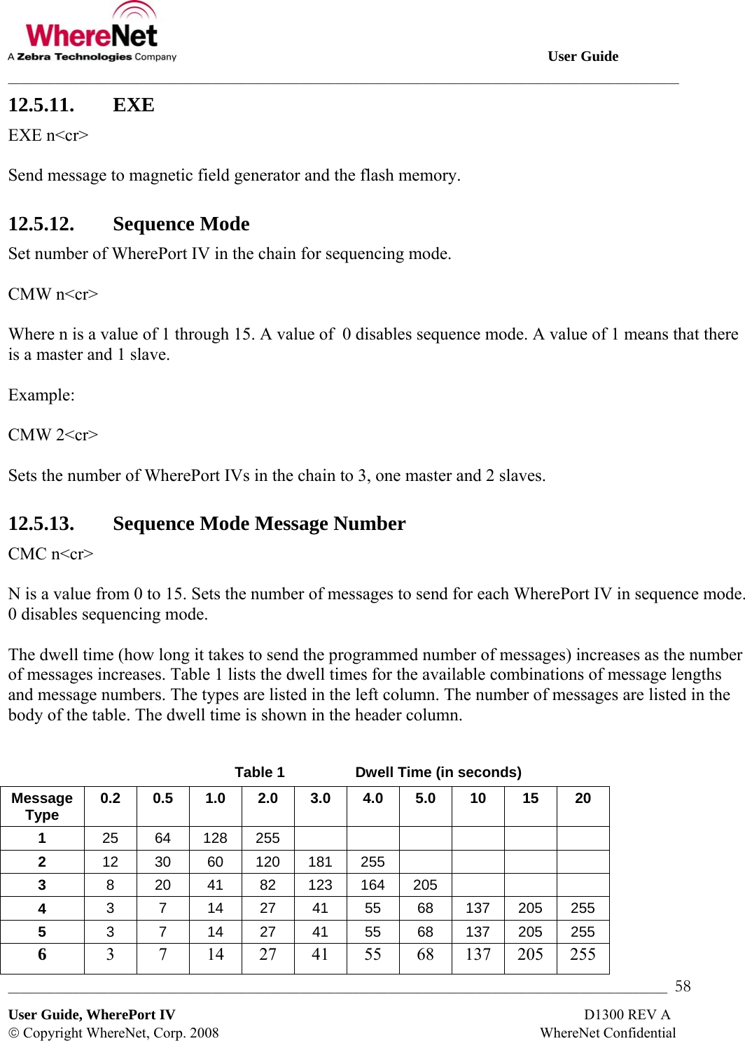
![User Guide ___________________________________________________________________________________________________________________ _________________________________________________________________________________________________________________ 57 User Guide, WherePort IV D1300 REV A © Copyright WhereNet, Corp. 2008 WhereNet Confidential Example: CNT 4<cr> Sets the blink count to 4. 12.5.8. Interval Set the WherePort IV response blink interval (44 bit message only ) where n is 0 to 7. INT n<cr> 12.5.9. Trigger Set the re-trigger response (44 bit message only). TRG n<cr> Where n is a value 0 through 15. Example: TRG 4<cr> Sets the re-trigger response to 10 sec. 12.5.10. Data Set the 96 bit data payload (144 bit message only). DAT [string]<cr> String of 24 ASCII-HEX characters; set the 96 bit data payload (144 bit message only). String of 22 ASCII-HEX characters: set the 96 bit data payload, payload CRC automatically calculated (144 bit message only). Example: DAT string<cr> A string of 24 ASCII-HEX characters to set the 96-bit data payload of the WherePort IV.](https://usermanual.wiki/Zebra-Technologies/WPT-3400/User-Guide-987925-Page-57.png)