Zebra Technologies WT41N0 Wearable Terminal User Manual Part 1

Zebra Technologies Corporation Wearable Terminal Part 1

User Manual Part 1

WT41N0WEARABLE TERMINALUSER GUIDEDRAFT
DRAFT
WT41N0 WEARABLE TERMINALUSER GUIDE72E-159561-01Rev. 1February 2012DRAFT
ii WT41N0 User GuideNo part of this publication may be reproduced or used in any form, or by any electrical or mechanical means, without permission in writing from Motorola. This includes electronic or mechanical means, such as photocopying, recording, or information storage and retrieval systems. The material in this manual is subject to change without notice.The software is provided strictly on an “as is” basis. All software, including firmware, furnished to the user is on a licensed basis. Motorola grants to the user a non-transferable and non-exclusive license to use each software or firmware program delivered hereunder (licensed program). Except as noted below, such license may not be assigned, sublicensed, or otherwise transferred by the user without prior written consent of Motorola. No right to copy a licensed program in whole or in part is granted, except as permitted under copyright law. The user shall not modify, merge, or incorporate any form or portion of a licensed program with other program material, create a derivative work from a licensed program, or use a licensed program in a network without written permission from Motorola. The user agrees to maintain Motorola’s copyright notice on the licensed programs delivered hereunder, and to include the same on any authorized copies it makes, in whole or in part. The user agrees not to decompile, disassemble, decode, or reverse engineer any licensed program delivered to the user or any portion thereof.Motorola reserves the right to make changes to any software or product to improve reliability, function, or design.Motorola does not assume any product liability arising out of, or in connection with, the application or use of any product, circuit, or application described herein.No license is granted, either expressly or by implication, estoppel, or otherwise under any Motorola, Inc., intellectual property rights. An implied license only exists for equipment, circuits, and subsystems contained in Motorola products.DRAFT
iiiRevision HistoryChanges to the original manual are listed below:Change Date DescriptionDRAFT
iv WT41N0 User GuideDRAFT
TABLE OF CONTENTSRevision History..............................................................................................................................  iiiAbout This GuideIntroduction .....................................................................................................................................  ixDocumentation Set ...................................................................................................................  ixConfigurations.................................................................................................................................  xSoftware Versions.....................................................................................................................  xChapter Descriptions ......................................................................................................................  xiNotational Conventions...................................................................................................................  xiRelated Documents and Software ..................................................................................................  xiiService Information.........................................................................................................................  xiiChapter 1: Getting StartedIntroduction ....................................................................................................................................  1-1Unpacking the Wearable Terminal .................................................................................................  1-3Getting Started ...............................................................................................................................  1-6Installing and Removing the Main Battery  .....................................................................................  1-6Installing the Main Battery ........................................................................................................  1-6Charging the Battery ......................................................................................................................  1-7Charging the Main Battery and Memory Backup Battery .........................................................  1-7Charging Spare Batteries .........................................................................................................  1-8Removing the Main Battery ......................................................................................................  1-8Installing the Wrist Mount ...............................................................................................................  1-9Install a Hip Mount  .........................................................................................................................  1-11Routing an Extended Cable Scanner .......................................................................................  1-12Connecting a Scanner  ...................................................................................................................  1-13Starting the Wearable Terminal  .....................................................................................................  1-13WT41N0 Boot Up .....................................................................................................................  1-13Voice Only WT41N0 Boot Up  ..................................................................................................  1-14Chapter 2: Using the Wearable TerminalIntroduction ....................................................................................................................................  2-1DRAFT
vi WT41N0 User GuidePower Button  .................................................................................................................................  2-1LED Indicators  ...............................................................................................................................  2-2Keypads .........................................................................................................................................  2-4Two-color Alphanumeric Keypad .............................................................................................  2-4Voice Only Keypad  ..................................................................................................................  2-7Display ...........................................................................................................................................  2-8App Launcher Window .............................................................................................................  2-8Windows CE 7.0 Desktop  ........................................................................................................  2-9Status Icons  .......................................................................................................................  2-9Programs Menu  .......................................................................................................................  2-10Control Panel  ...........................................................................................................................  2-12Using the Keypad to Navigate Applications .............................................................................  2-13Key Combinations ..............................................................................................................  2-13Selecting Items  ..................................................................................................................  2-13Navigating Menus  ..............................................................................................................  2-14Navigating Tabs  .................................................................................................................  2-14Navigating Fields  ...............................................................................................................  2-14Selecting Checkboxes and Radio Buttons .........................................................................  2-15Selecting Items in a List  .....................................................................................................  2-15Screen Calibration  ...................................................................................................................  2-15Special Character Keypad  .............................................................................................................  2-16Resetting the Wearable Terminal  ..................................................................................................  2-17Performing a Warm Boot  ...................................................................................................  2-17Performing a Cold Boot ......................................................................................................  2-18Waking the Wearable Terminal  .....................................................................................................  2-19Battery Health  ................................................................................................................................  2-19Chapter 3: Data CaptureIntroduction ....................................................................................................................................  3-1Laser Scanning ........................................................................................................................  3-1Scanning Considerations .........................................................................................................  3-1Scanning Bar Codes ................................................................................................................  3-2Scanning Tips  ....................................................................................................................  3-2Scan LED Indicator ..................................................................................................................  3-2Imaging ..........................................................................................................................................  3-3Operational Modes ...................................................................................................................  3-3Imager Scanning ......................................................................................................................  3-3Chapter 4: Wireless ApplicationsIntroduction ....................................................................................................................................  4-1Signal Strength Icon  ......................................................................................................................  4-2Turning Off the Radio  ....................................................................................................................  4-3Minimum Setup ..............................................................................................................................  4-3Chapter 5: AccessoriesIntroduction ....................................................................................................................................  5-1Single Slot USB Cradle ..................................................................................................................  5-3Battery Charging Indicators  .....................................................................................................  5-4DRAFT
Table of Contents viiFour Slot Ethernet Cradle  ..............................................................................................................  5-5Battery Charging  ......................................................................................................................  5-5LED Charge Indications  ...........................................................................................................  5-6Speed LED ...............................................................................................................................  5-6Link LED  ..................................................................................................................................  5-6Battery Charging Indicators  .....................................................................................................  5-6Four Slot Spare Battery Charger  ...................................................................................................  5-7Spare Battery Charging with the Four Slot Spare Battery Charger ..........................................  5-7Battery Charging Indicators  .....................................................................................................  5-7RS409/RS419 Scanner ..................................................................................................................  5-8RS309 Scanner ..............................................................................................................................  5-10RS507 Imager ................................................................................................................................  5-12Freezer Pouch  ...............................................................................................................................  5-12Wired Headset  ...............................................................................................................................  5-14Connector Shroud ..........................................................................................................................  5-16Assembly .................................................................................................................................  5-16Disconnecting the Cable from the Wearable Terminal .............................................................  5-16Chapter 6: Maintenance & TroubleshootingIntroduction ....................................................................................................................................  6-1Maintaining the Wearable Terminal  ...............................................................................................  6-1Wrist Mount Cleaning Instructions  ...........................................................................................  6-2Arm Sleeve Cleaning Instructions ............................................................................................  6-2Removing the Screen Protector .....................................................................................................  6-2Battery Safety Guidelines  ..............................................................................................................  6-3Cleaning .........................................................................................................................................  6-4Materials Required ...................................................................................................................  6-4Cleaning the Wearable Terminal  .............................................................................................  6-4Housing ..............................................................................................................................  6-4Display ...............................................................................................................................  6-4Connectors .........................................................................................................................  6-4Cleaning the RS309, RS409, RS419 and RS507 ....................................................................  6-5Housing ..............................................................................................................................  6-5Scanner Exit Window .........................................................................................................  6-5Connectors .........................................................................................................................  6-5Cleaning Cradle Connectors ....................................................................................................  6-6Cleaning Frequency .................................................................................................................  6-6Troubleshooting .............................................................................................................................  6-7Wearable Terminal ...................................................................................................................  6-7Four Slot Ethernet Cradle  ........................................................................................................  6-11Four Slot Spare Battery Charger  .............................................................................................  6-12Single Slot USB Cradle ............................................................................................................  6-13Appendix A: SpecificationsTechnical Specifications  ................................................................................................................  A-1Wearable Terminal ...................................................................................................................  A-1RS309 Scanner ........................................................................................................................  A-3RS409 Scanner ........................................................................................................................  A-4RS419 Scanner ........................................................................................................................  A-5DRAFT
viii WT41N0 User GuideRS507 Scanner ........................................................................................................................  A-6GlossaryIndexDRAFT
ABOUT THIS GUIDEIntroductionThis guide provides information about using the WT41N0 family of mobile terminals and accessories. The WT41N0 has two versions, one with a display and a voice only version without a display. Throughout this guide Voice Only WT41N0 refers to the version without the display and WT41N0 refers to the version with a display.Documentation SetThe documentation set for the WT41N0 is divided into guides that provide information for specific user needs.•WT41N0 Quick Start Guide - •Voice Only WT41N0 Quick Start Guide - •WT41N0 User Guide - describes how to use the WT41N0 wearable terminal.•WT41N0 Integrator Guide - describes how to set up the WT41N0 wearable terminal and the accessories.•EMDK Help File - provides API information for writing applications.NOTE Screens and windows pictured in this guide are samples and can differ from actual screens.DRAFT
x WT41N0 User GuideConfigurationsThis guide covers the following configurations:Software VersionsThis guide covers various software configurations and references are made to operating system or software versions for:•OEM version•Fusion version.OEM SoftwareTo determine the OEM software version:1. Press CTRL and then ESC to open the Start menu.2. Using the navigation keys, select Settings.3. Press the Blue key and the down arrow to open the Control Panel sub-menu.4. Press ENTER key to launch Control Panel.5. Using the navigation keys, select the System Information icon.6. Press ENTER key to launch System Information applet.Configuration Radios Display Memory DataCaptureOperatingSystem KeypadsWT41N0 WLAN: 802.11a/b/g/nWPAN: Bluetooth2.8” QVGA Color; non-touch2 GB Flash/512 MB RAM Optional accessory Windows CE 7.0 ProfessionalTwo-color Alphanumeric Keypad2.8” QVGA Color; touch2 GB Flash/512 MB RAM Optional accessory Windows CE 7.0 ProfessionalTwo-color Alphanumeric KeypadVoice Only WT41N0 WLAN: 802.11a/b/g/nWPAN: BluetoothNone 2 GB Flash/512 MB RAM Optional accessory Windows CE 7.0 ProfessionalThree programmable keysNOTE To view the software versions on the Voice Only WT41N0, the Voice Only WT41N0 must be connected to a host computer running remote desktop software. Refer to the WT41N0 Integrator Guide for more information.DRAFT
About This Guide xiFusion SoftwareTo determine the Fusion software version:1. Press ALT - w. The Wireless menu appears.2. Using the navigation keys, select Wireless Status.3. Press ENTER. The Wireless Status window displays.4. Press 5. The Versions screen appears.Chapter DescriptionsTopics covered in this guide are as follows:•Chapter 1, Getting Started, provides information on getting the wearable terminal up and running for the first time.•Chapter 2, Using the Wearable Terminal, explains how to use the wearable terminal. This includes instructions for powering on and resetting the wearable terminal, entering and capturing data.•Chapter 5, Accessories, describes the accessories available for the wearable terminal and how to use the accessories with the wearable terminal.•Chapter 6, Maintenance & Troubleshooting, includes instructions on cleaning and storing the wearable terminal, and provides troubleshooting solutions for potential problems during wearable terminal operation.•Appendix A, Specifications, includes a table listing the technical specifications for the wearable terminal.Notational ConventionsThe following conventions are used in this document:•“Wearable terminal” refers to the WT41N0 series of wearable terminals.•Italics are used to highlight the following:•Chapters and sections in this guide•Related documentsDRAFT
xii WT41N0 User Guide•Bold text is used to highlight the following:•Dialog box, window and screen names•Drop-down list and list box names•Check box and radio button names•Icons on a screen•Key names on a keypad•Button names on a screen.•Bullets (•) indicate:•Action items•Lists of alternatives•Lists of required steps that are not necessarily sequential.•Sequential lists (e.g., those that describe step-by-step procedures) appear as numbered lists.Related Documents and SoftwareThe following documents provide more information about the WT41N0 wearable terminals.•WT41N0 Quick Start Guide, p/n 72-157178-xx•Voice Only WT41N0 Quick Start Guide, p/n 72-xxxxxx-xx•WT41N0 Regulatory Guide, p/n 72-159559-xx•WT41N0 Integrator Guide, p/n 72E-160600-xx•RS309 Scanner Quick Reference Guide, p/n 72-86011-xx•RS409 Scanner Quick Reference Guide, p/n 72-86010-xx•RS419 Scanner Quick Reference Guide, p/n 72-86010-xx•RS507 Hands-free Imager Quick Reference Guide, p/n 72-115987-xx•RS507 Hands-free Imager Product Reference Guide, p/n 72E-120802-xx•Wireless Fusion Enterprise Mobility Suite User Guide for Version 1.XX, p/n 72E-xxxxxx-xx•Enterprise Mobility Developer Kits, available at: http://www.motorola.com/enterprisemobility/support.•Device Configuration Package (DCP for WT41N0c50) and Platform SDK (PSDK9090c70) for WT41N0 with Windows CE 7.0, available at: http://www.motorola.com/enterprisemobility/support.•ActiveSync software, available at: http://www.microsoft.com.For the latest version of this guide and all guides, go to: http://www.motorola.com/enterprisemobility/manuals.Service InformationIf you have a problem with your equipment, contact Motorola Enterprise Mobility support for your region. Contact information is available at: http://www.motorola.com/enterprisemobility/contactsupport.When contacting Enterprise Mobility support, please have the following information available:•Serial number of the unitDRAFT
About This Guide xiii•Model number or product name•Software type and version numberMotorola responds to calls by email, telephone or fax within the time limits set forth in support agreements.If your problem cannot be solved by Motorola Enterprise Mobility Support, you may need to return your equipment for servicing and will be given specific directions. Motorola is not responsible for any damages incurred during shipment if the approved shipping container is not used. Shipping the units improperly can possibly void the warranty.If you purchased your Enterprise Mobility business product from a Motorola business partner, contact that business partner for support.DRAFT
xiv WT41N0 User GuideDRAFT
CHAPTER 1 GETTING STARTEDIntroductionThis chapter lists the parts and accessories for the wearable terminal and explains how to install and charge the batteries and start the wearable terminal for the first time.Figure 1-1WT41N0 Wearable Terminal Front ViewApplicationKeypadDisplayCharge Status LEDData Entry KeypadPower ButtonAction Keypad SpeakerMicrophoneDRAFT
1 - 2 WT41N0 User GuideFigure 1-2Voice Only WT41N0 Wearable Terminal Front ViewFigure 1-3Wearable Terminal Back ViewTable 1-1Parts of the Wearable Terminal Item DescriptionDisplay Displays the application and data stored on the device. (WT41N0 only)Power Button Places the wearable terminal in to the suspend mode or resumes normal operation.Performs a warm boot when held down for five seconds. See Resetting the Wearable Terminal on page 2-17 for information about performing a warm boot.Charge Status LED Indicates the charging status of the battery.Charge Status LEDWLAN Status LEDPower ButtonAction Keypad SpeakerApplication Controlled LED Battery Status LEDBatteryInterface ConnectorRubber PlugInterface Connector(shown without Rubber Plug)Cradle ConnectorCleatBattery ReleaseDRAFT
Getting Started 1 - 3Unpacking the Wearable TerminalCarefully remove all protective material from around the wearable terminal and save the shipping container for later storage and shipping.Verify that you received all equipment listed below:•Wearable terminal•Lithium-ion battery•Regulatory Guide•Quick Start Guide.Inspect the equipment for damage. If you are missing any equipment or if you find any damaged equipment, contact the Motorola Solutions Global Customer Support Center immediately. See page xii for contact information.WLAN Status LED Indicates the status of the wireless connection. (Voice Only WT41N0 only)Battery Status LED Indicates when the battery charge level falls below 30%. (Voice Only WT41N0 only)Application Controlled LED Application programmable. (Voice Only WT41N0 only)MicrophoneSpeaker Provides audio playback.Keypads Enable user input.Battery Provides power to the wearable terminal.Interface Connector Provides electrical connection to an accessory, such as a scanner.Cradle Connector Provides electrical connection to a cradle.Battery Release Releases the battery for removal.Cleat Provides mounting for the wrist mount and cradles.Table 1-1Parts of the Wearable Terminal (Continued)Item DescriptionDRAFT
1 - 4 WT41N0 User GuideFigure 1-4RS419 ScannerFigure 1-5RS309 ScannerScan LEDExit WindowRing MountFinger StrapConnectorScan Trigger Trigger AssemblyRotating Scan AssemblyScan LEDTrigger ConnectorProtective CapExit WindowScan Button Trigger CableInterface CableDRAFT
Getting Started 1 - 5Figure 1-6RS507 ScannerDRAFT
1 - 6 WT41N0 User GuideGetting StartedIn order to start using the wearable terminal for the first time:•Install the main battery•Charge the main battery and backup battery•Install the wearable terminal onto the wrist mount•Install an optional scanner•Start the wearable terminal.Installing and Removing the Main BatteryInstalling the Main BatteryBefore using the wearable terminal, install a lithium-ion (Li-ion) battery by placing the battery into the wearable terminal as shown in Figure 1-7.When a battery is installed in a wearable terminal for the first time the wearable terminal boots and powers on automatically.Figure 1-7Installing the Main BatteryNOTE The main battery can be charged before or after installation into the wearable terminal. Use the Single Slot USB cradle or Four Slot Spare Battery Charger to charge the main battery before installation, or the Single Slot USB cradle or Four Slot Ethernet cradle to charge the main battery after installation.NOTE Ensure the battery is fully inserted. An audible click can be heard as the battery is fully inserted. A partially inserted battery may result in unintentional data loss.DRAFT
Getting Started 1 - 7Charging the BatteryCharging the Main Battery and Memory Backup BatteryBefore using the wearable terminal for the first time, charge the main battery until the amber Charge Status LED remains lit (see Table 1-2 on page 1-7 for charge status indications).The wearable terminal is equipped with a memory backup battery which automatically charges from the main battery whether or not the wearable terminal is operating or is in suspend mode. The memory backup battery retains data in memory for at least 30 minutes when the wearable terminal's main battery is removed or fully discharged. When the wearable terminal is used for the first time or after the memory backup battery has fully discharged, the memory backup battery requires approximately 15 hours to fully charge. Do not remove the main battery from the wearable terminal for 15 hours to ensure that the memory backup battery fully charges. If the main battery is removed from the wearable terminal or the main battery is fully discharged, the memory backup battery completely discharges in several hours.When the wearable terminal reaches a very low battery state, the combination of main battery and backup battery retains data in memory for at least 24 hours.Charge the wearable terminal with an installed main battery using either the Single Slot USB cradle or the Four Slot Ethernet cradle.To charge the main battery:1. Ensure the cradle used to charge the main battery is connected to the appropriate power source.2. Insert the wearable terminal into a cradle.3. The wearable terminal starts to charge automatically. The amber Charge Status LED lights to indicate the charge status. See Table 1-2 for charging indications. The standard capacity battery fully charges in less than four hours and the extended battery fully charges in less than eight hours.CAUTION Ensure that you follow the guidelines for battery safety described in Battery Safety Guidelines on page 6-3.NOTE Do not remove the main battery within the first 15 hours of use. If the main battery is removed before the backup battery is fully charged, data may be lost.Table 1-2Wearable Terminal LED Charge Indicators LED IndicationOff Wearable terminal is not in cradle. Wearable terminal not placed correctly. Charger is not powered.Fast Blinking Amber Charging error:•Temperature is too low or too high.•Charging has gone on too long without completing (typically eight hours).Slow Blinking AmberWearable terminal is charging.Solid Amber Charging complete.Note: When the battery is initially inserted in the wearable terminal, the amber LED flashes once if the battery power is low or the battery is not fully inserted.DRAFT
1 - 8 WT41N0 User GuideCharging Spare BatteriesUse the following accessories to charge spare batteries:•Single Slot USB Cradle•Four Slot Spare Battery Charger.To charge a spare battery:1. Ensure the accessory used to charge the spare battery is connected to the appropriate power source.2. Insert the spare battery into the accessory’s spare battery charging slot with the charging contacts facing down (over the charging pins) and gently press down on the battery to ensure proper contact.3. The battery starts to charge automatically. The amber charge LED on the accessory lights to show the charge status. See Chapter 5, Accessories for accessory charge LED indicator definitions.The standard capacity battery fully charges in less than four hours and the extended capacity battery fully charges in less than eight hours.Removing the Main BatteryTo remove the main battery:1. Prior to removing the battery, ensure that the wearable terminal is in suspend mode. If the wearable terminal is not in suspend mode, press the Power button to place the wearable terminal in suspend mode.2. Press the battery release button. The battery partially ejects from the wearable terminal.3. Remove the battery from the wearable terminal.Figure 1-8Removing the Main BatteryBattery ReleaseDRAFT
Getting Started 1 - 9Installing the Wrist MountThe wrist mount provides the mounting of the wearable terminal on the forearm for hands-free applications. Refer to the Wrist Mount Installation Guide for information on the wrist mount.Figure 1-9Wrist MountTo install the wrist mount:1. Determine which arm the wrist mount will be used on.2. Install the short strap on the end closest to the wrist.3. Install the long strap on the other end.4. Slide the hand into the wrist mount.5. Tighten the straps.6. Align the cleat on the back of the wearable terminal with the mounting bracket on the wrist mount.Figure 1-10Aligning the Cleat7. Slide the wearable terminal onto the wrist mount until it clicks into place.8. If necessary, loosen and re-tighten the straps.Mounting BracketRelease LeverMounting BracketDRAFT
1 - 10 WT41N0 User GuideFigure 1-11Wearable Terminal and Wrist MountTo remove the wearable terminal from the wrist mount, press down on the release lever and slide the wearable terminal out.Figure 1-12Wearable Terminal RemovalRelease LeverDRAFT
Getting Started 1 - 11Install a Hip MountThe hip mount allows the user to mount the wearable terminal on the hip for use in voice picking applications. An RS309, RS409 or RS419 scanner with an extended cable is required when using the hip mount.Slide the wearable terminal into the hip mount.Figure 1-13Insert Wearable Terminal into Hip MountClose the front flap followed by the back flap.Figure 1-14Close Hip Mount FlapsSlide a belt through the belt loop on the back of the hip mount. The wearable terminal can be mounted right-side up or up-side down depending upon user preference or application.DRAFT
1 - 12 WT41N0 User GuideFigure 1-15Hip Mount on BeltConnect accessories as required.Routing an Extended Cable ScannerWhen using an RS309, RS409 or RS419 scanner with the wearable terminal mounted on the hip, the extended cable version is required.Motorola offers for sale cable clips, which attach to clothing and hold the scanner cable so that the cable does not interfere with the user. The cable clips are similar to badge clips and can be purchased at any office supply store as well.Figure 1-16Routing RS409/419 Scanner Cable from Hip to HandDRAFT
Getting Started 1 - 13Figure 1-17Routing RS309 Scanner Cable from Hip to HandConnecting a ScannerThe RS309, RS409 and RS419 scanners and the RS507 imager can be used with the wearable terminal. See RS309 Scanner on page 5-10 and RS409/RS419 Scanner on page 5-8 for procedures for connecting the scanner to the wearable terminal. Refer to the RS507 Product Reference Guide for procedures for connecting the imager to the wearable terminal.Starting the Wearable TerminalPress the Power button to turn on the wearable terminal. If the wearable terminal does not power on, perform a cold boot. See Resetting the Wearable Terminal on page 2-17. WT41N0 Boot UpWhen the WT41N0 is powered on for the first time the splash screen (Figure 1-18) appears for a short period of time followed by the Start Up window on non-touch configurations and the calibration screen on touch enabled configurations.NOTE When a battery is fully inserted in a wearable terminal for the first time, upon the wearable terminal’s first power up, the device cold boots and powers on automatically.DRAFT
1 - 14 WT41N0 User GuideFigure 1-18 Splash ScreenFigure 1-19Start Up WindowUse the Calibration screen to align the touch screen:1. Carefully press and briefly hold on the center of the Calibration screen target. Repeat the procedure as the target moves and stops at different locations on the screen. This enters the new calibration settings. Figure 1-20Calibration Screen2. Once all of the new calibration settings are input, tap the screen or press the ENTER button to save the new calibration settings. Press ESC to discard the new calibration settings.Voice Only WT41N0 Boot UpWhen the Voice Only WT41N0 is powered on for the first time the three LEDs on the front housing blink as follows:1. Application Controlled LED and Battery Status LED on.2. All LEDs Off.3. Application Controlled LED on, Battery Status LED on, WLAN Status LED on.Calibration Screen Confirm Calibration ScreenDRAFT
Getting Started 1 - 154. WLAN Status LED off, Battery Status LED off, Application Controlled LED off.The WLAN Status LED blinks indicating that the wireless connection is not connected or is solid indicating that the wireless connection is connected.DRAFT
1 - 16 WT41N0 User GuideDRAFT
CHAPTER 2 USING THE WEARABLETERMINALIntroductionThis chapter explains the physical buttons and controls on the wearable terminal, and provides basic instructions for using the wearable terminal, including powering on and resetting the wearable terminal, using a headset, entering information and scanning.This chapter also details the operation of the Windows CE 7.0 operating system including the desktop, applications and settings. Depending upon the programs installed on the wearable terminal, some of these items may not be available.Power ButtonPress the Power button to turn the wearable terminal screen on and off (suspend mode). The wearable terminal is on when the screen is on and the wearable terminal is in suspend mode when the screen is off. For more information, see Starting the Wearable Terminal on page 1-13.Figure 2-1Power ButtonThe Power button is also used to reset the wearable terminal by performing a warm or cold boot.•Warm Boot (Soft Reset) - Resets the wearable terminal.•Cold Boot (Hard Reset) - Resets the wearable terminal, removes all added applications and restores all factory default settings.Power ButtonDRAFT
2 - 2 WT41N0 User GuideLED IndicatorsThe Charge Status LED indicates the wearable terminal charging status when the WT41N0 is in a cradle. Table 2-1 describes the Charge Status LED indications.Figure 2-2Wearable Terminal LED IndicatorsTable 2-1Charge Status LED Indications LED State IndicationCharge Status LED (Amber) Off Wearable terminal is not in cradle. Wearable terminal not placed correctly. Charger is not powered.Slow Blinking Amber Main battery in wearable terminal is charging.Fast Blinking Amber Charging error:•Temperature is too low or too high.•Charging has gone on too long without completing (typically eight hours).Solid Amber Charging complete.Note: When the battery is initially inserted in the wearable terminal, the amber LED flashes once if the battery power is low or the battery is not fully inserted.Programmable LED1(Light Green) - Application dependentProgrammable LED2(Green) - Application dependentCharge Status LEDProgrammable LED2Programmable LED1DRAFT
Using the Wearable Terminal 2 - 3Figure 2-3Voice Only WT41N0 LED IndicatorsThe Voice Only WT41N0 has three status LEDs. Table 2-2 lists the default LED indications. LED functionality can be changed by an application.Table 2-2Voice Only WT41N0 LED Indications LED State IndicationWLAN Status LED (Green) Off Battery completely discharged or device error. Contact system administrator.Blinking Voice Only WT41N0 is not connected to a wireless network.Solid Voice Only WT41N0 is connected to a wireless network.Battery Status LED (Light Green) Off Battery charge level is greater than 30%Blinking Battery charge level is less than 30%.Application Controlled LED (Yellow) - Application dependent.WLAN Status LEDApplication Controlled LED Battery Status LED Charging Status LEDDRAFT
2 - 4 WT41N0 User GuideKeypadsThe wearable terminal has the following keypads:•Two-color alphanumeric keypad•Voice Only keypad.Two-color Alphanumeric KeypadThe two-color alphanumeric keypad contains application keys, scroll keys and function keys. The keypad is color-coded to indicate the alternate function keys (blue, orange and gray). Note that keypad functions can be changed by an application so the wearable terminal’s keypad may not function exactly as described. See Table 2-3 on page 2-4 for key and button descriptions and Table 2-4 on page 2-5 for the keypad’s special functions.Figure 2-4Two-color Alphanumeric KeypadTable 2-3Two-color Alphanumeric Keypad Descriptions Key DescriptionOrange Press and release the Orange key to activate alphabetic characters (shown on the keypad in orange). The   icon appears on the Windows CE desktop taskbar.Gray Press and release the Gray key to activate alphabetic characters (shown on the keypad in gray). The   icon appears on the Windows CE desktop taskbar.Blue Press and release the Blue key to activate the keypad alternate functions (shown on the keypad in blue). The   icon appears on the Windows CE desktop taskbar.DRAFT
Using the Wearable Terminal 2 - 5The keypad is color-coded to indicate the alternate function key (blue) values and the alternate ALPHA key (orange) values. See Table 2-4 for the special character generation.Scroll Keys Moves up or down from one item to another or increases/decreases specified values.Moves left or right from one item to another when used with the Blue key. For each left or right scroll, the Blue key must be pressed first.ESC  Exits the current operation.Alphanumeric  In default state, produces the numeric value on the key.In Left Alpha state, produces the lower case alphabetic characters in the orange area. In Right Alpha state, produces the lower case alphabetic characters in the gray area.When the SHIFT key is pressed in the Alpha state, the upper case alphabetic characters on the key are produced. For example, press and release the Orange key, press and release the SHIFT key and then press the 4 key once to produce the letter ‘G’.BKSP Backspace function. Space function when used with the Blue key.CTRL (Control) Press and release the CTRL key to activate the keypad alternate CTRL functions. The   icon appears on the Windows CE desktop taskbar.Press the Blue key followed by the CTRL key to activate the keypad alternate ALT functions. The   icon appears on the Windows CE desktop taskbar.SHIFT Press and release the SHIFT key to activate the keypad alternate SHIFT functions. The   icon appears on the Windows CE desktop taskbar.ENTER Executes a selected item or function.TAB Move the focus to the next field in a window.P1 Programmable key. When used with the Blue key, toggles the keypad backlight on and off.P2 Programmable key. When used with the Blue key, toggles the display backlight on and off.Table 2-4Special Character Generation Map  Special Character Two-color Keypad Triple-tap Keypad/(forward slash) Blue - Orange - 0Blue - Orange - 0[(open square bracket) Blue - Orange - 2Blue - Orange - 2](close square bracket) 
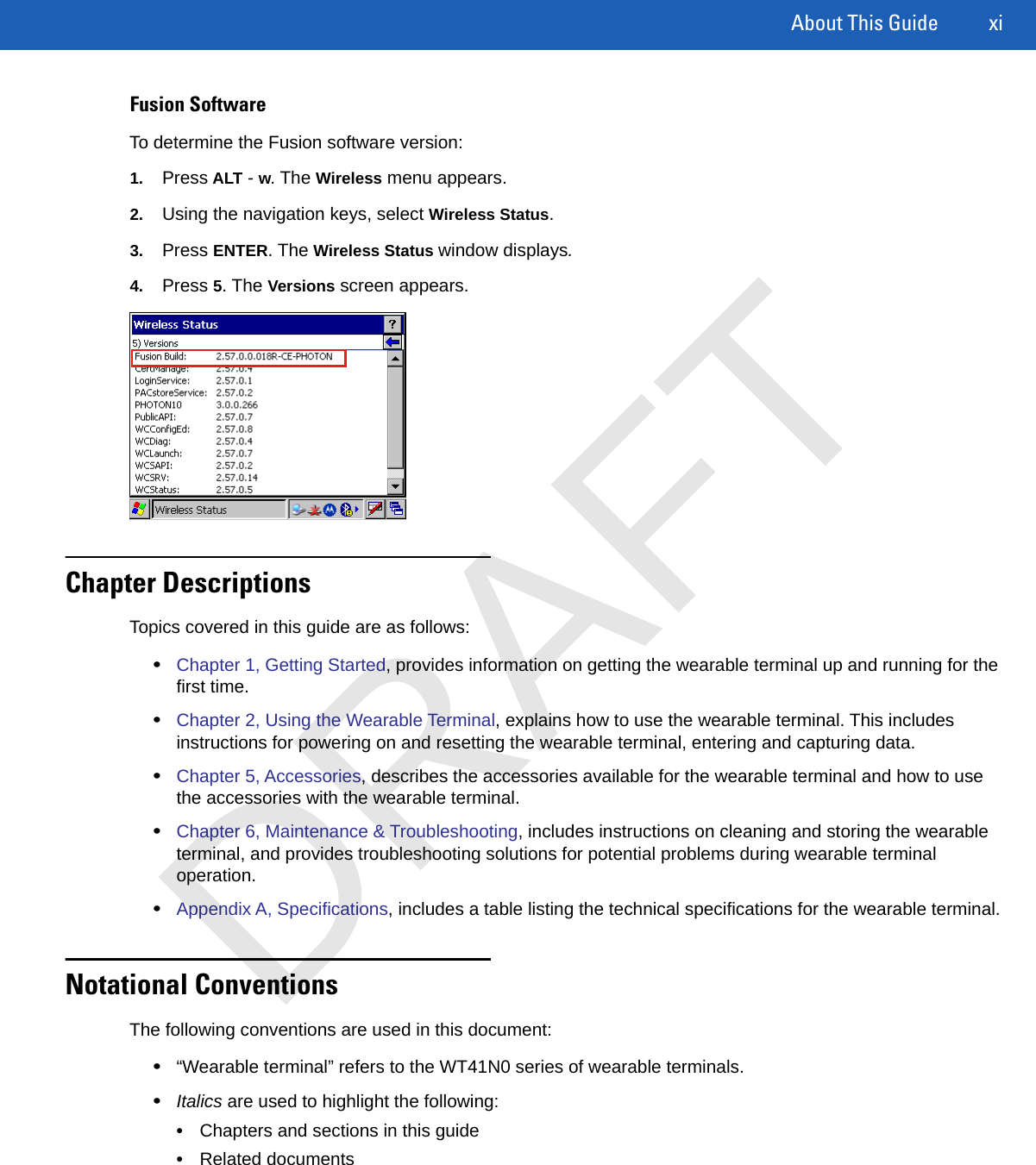
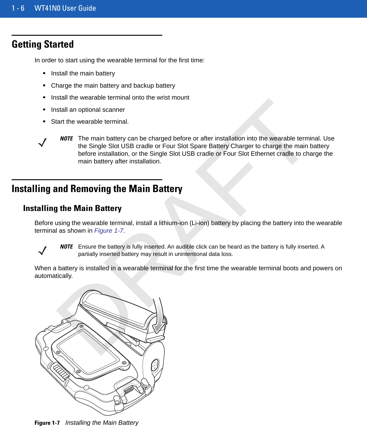
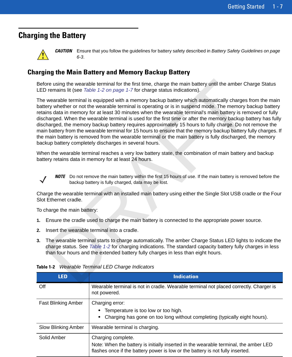
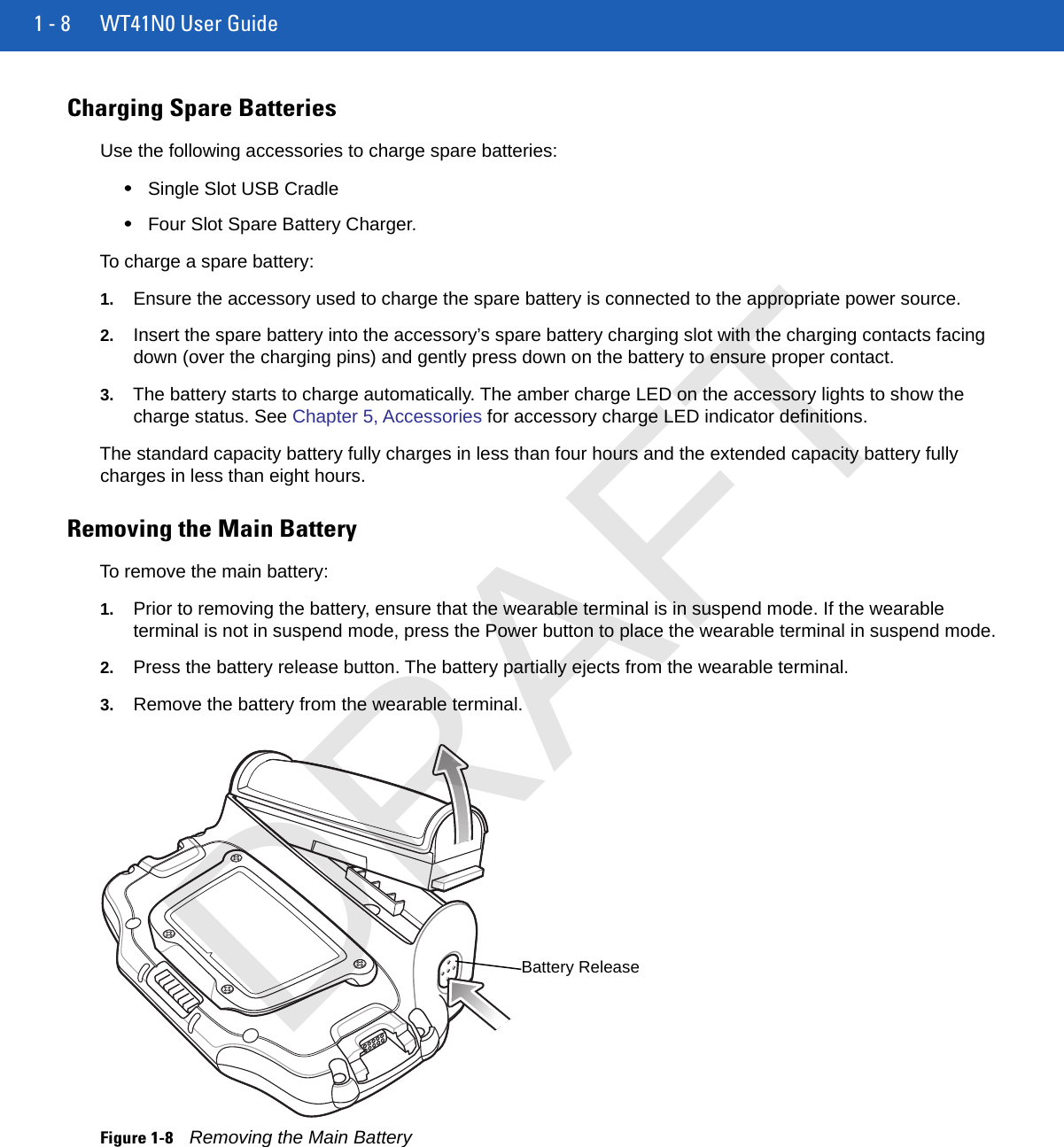
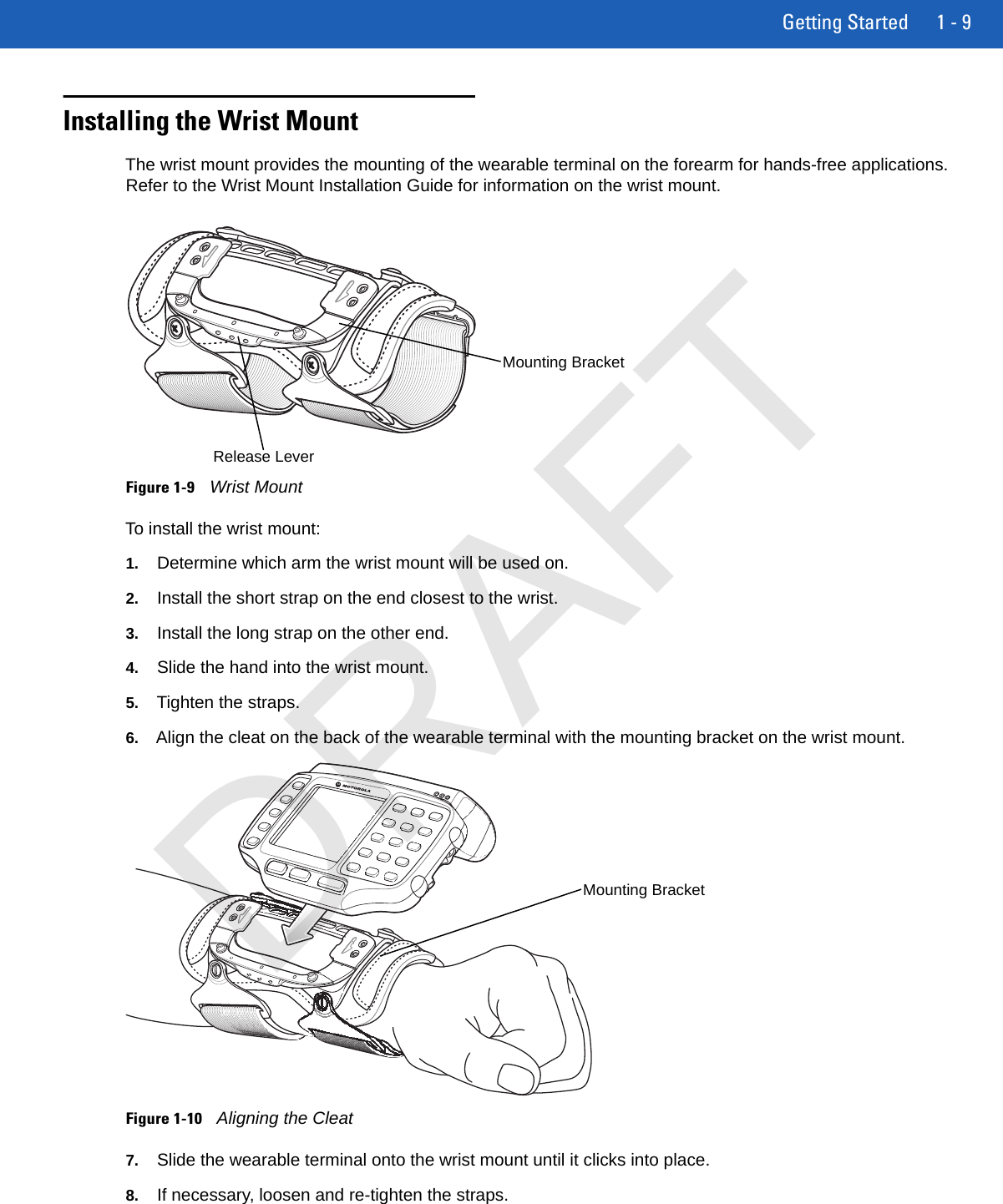
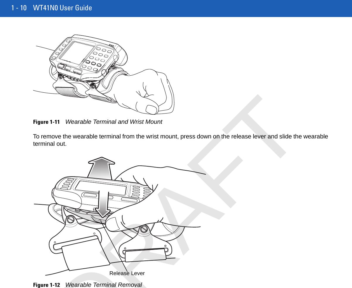
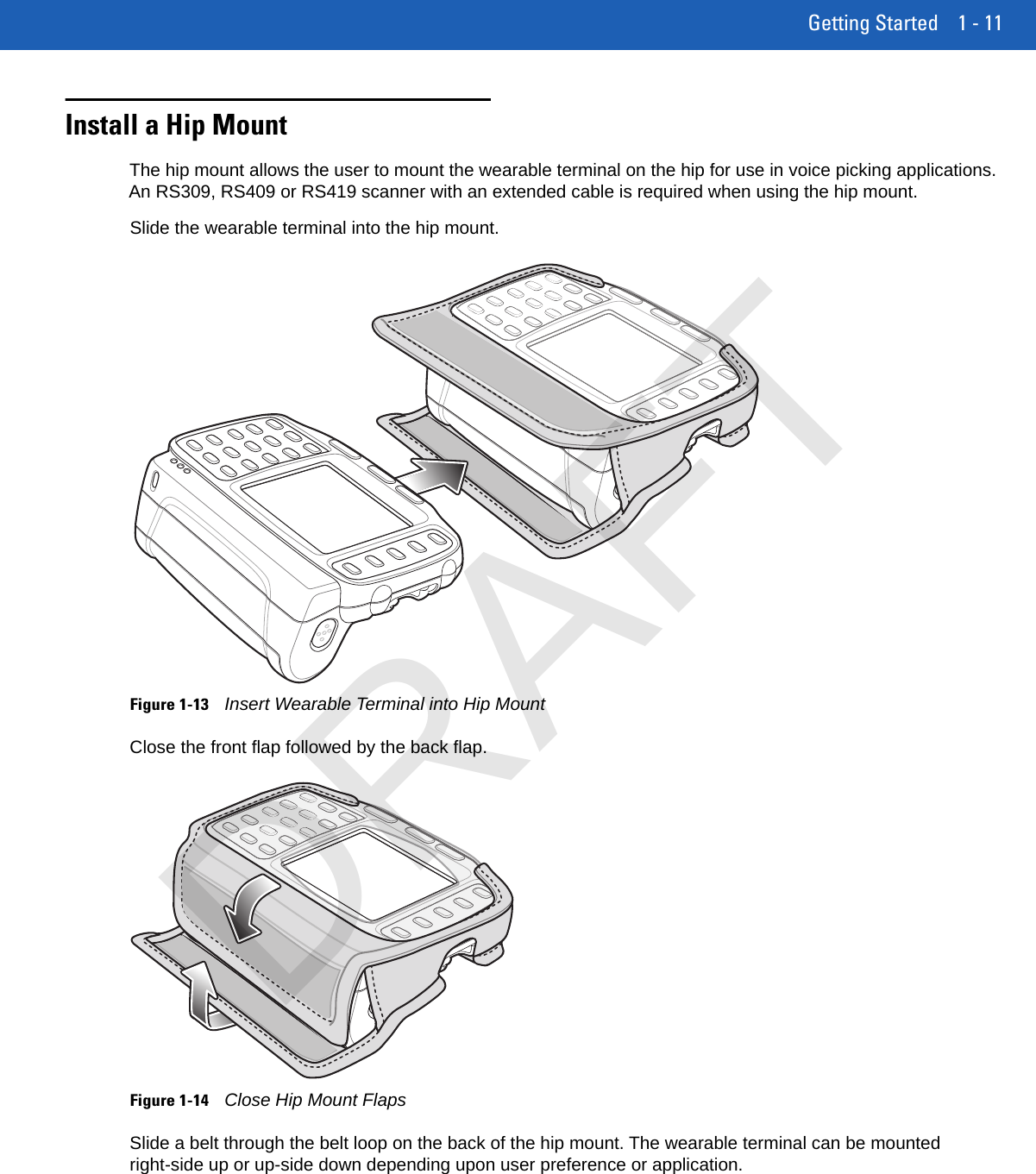
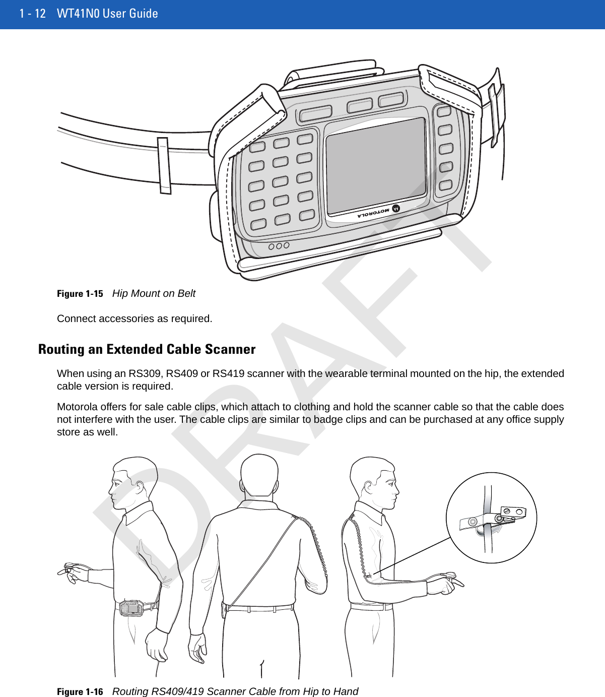
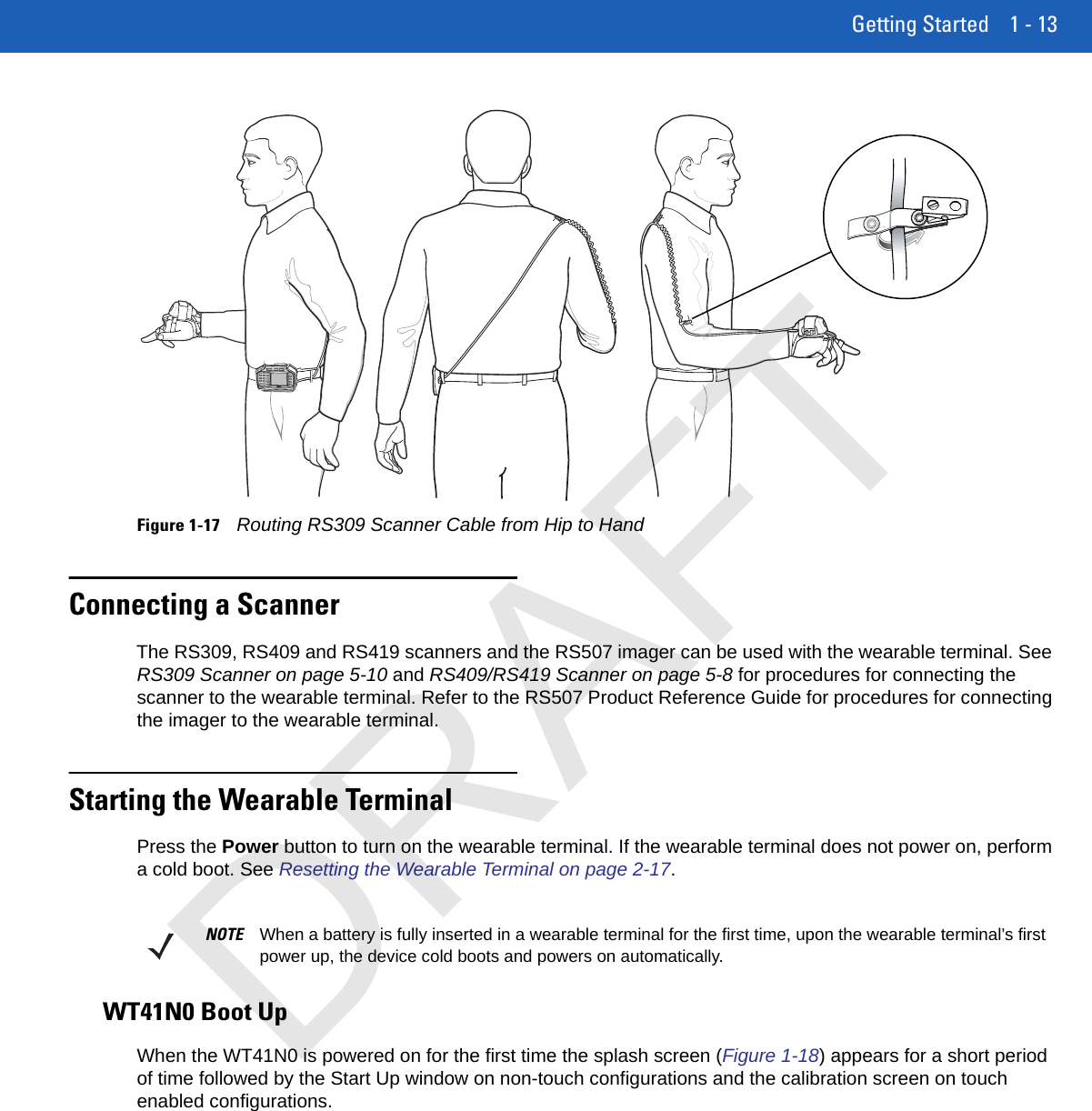
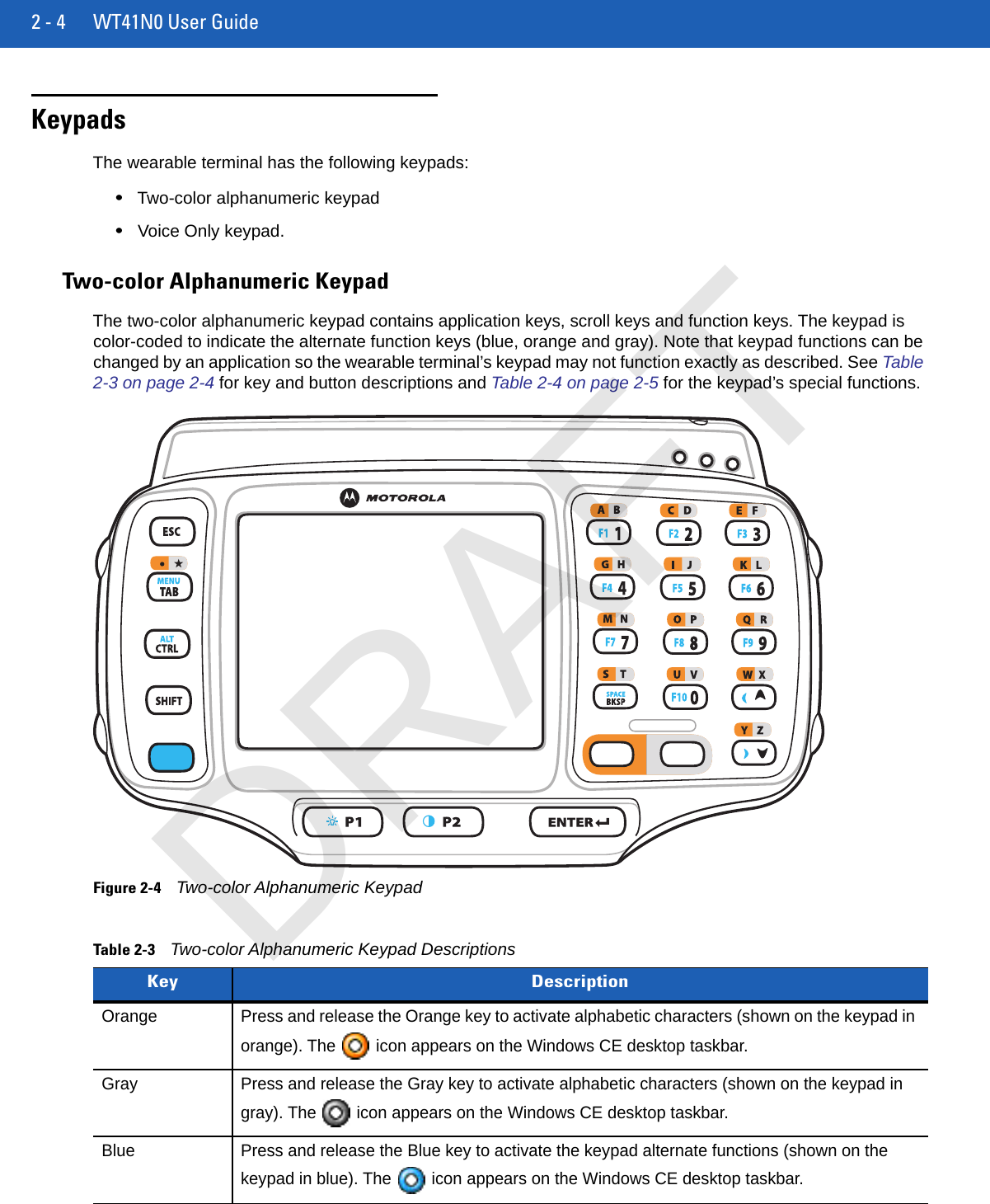
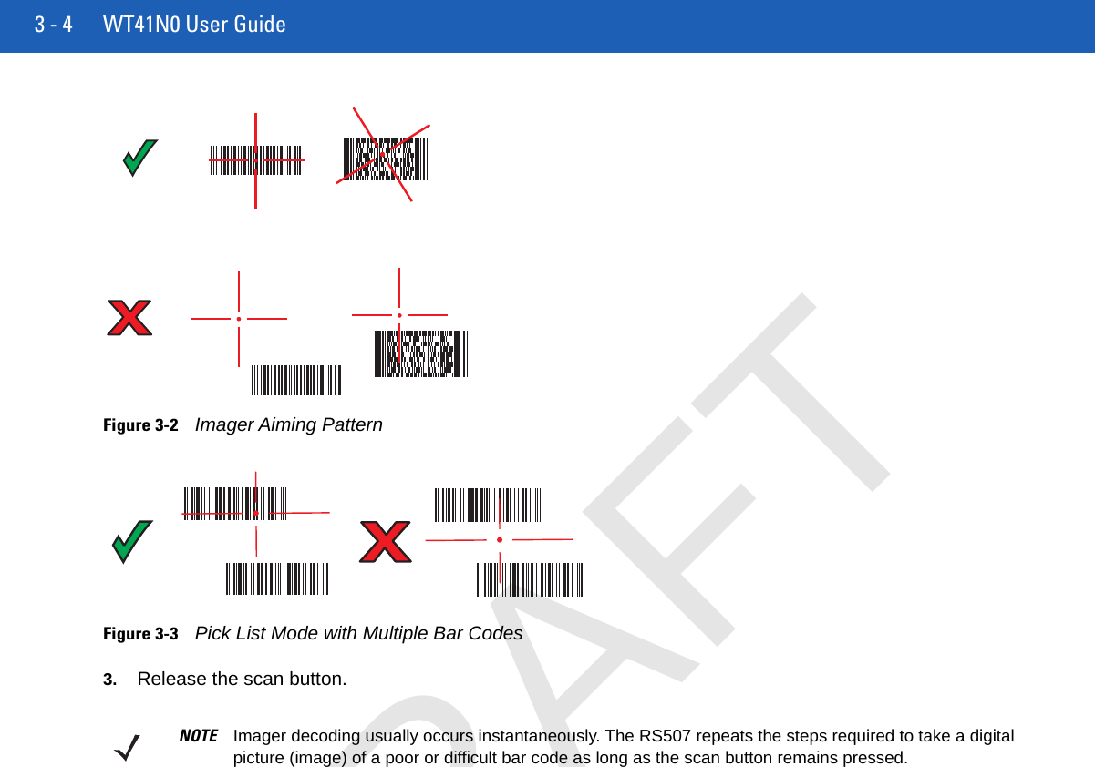
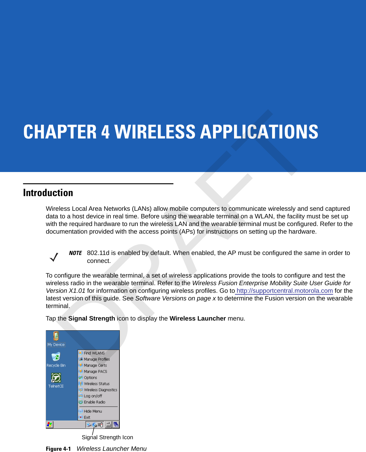
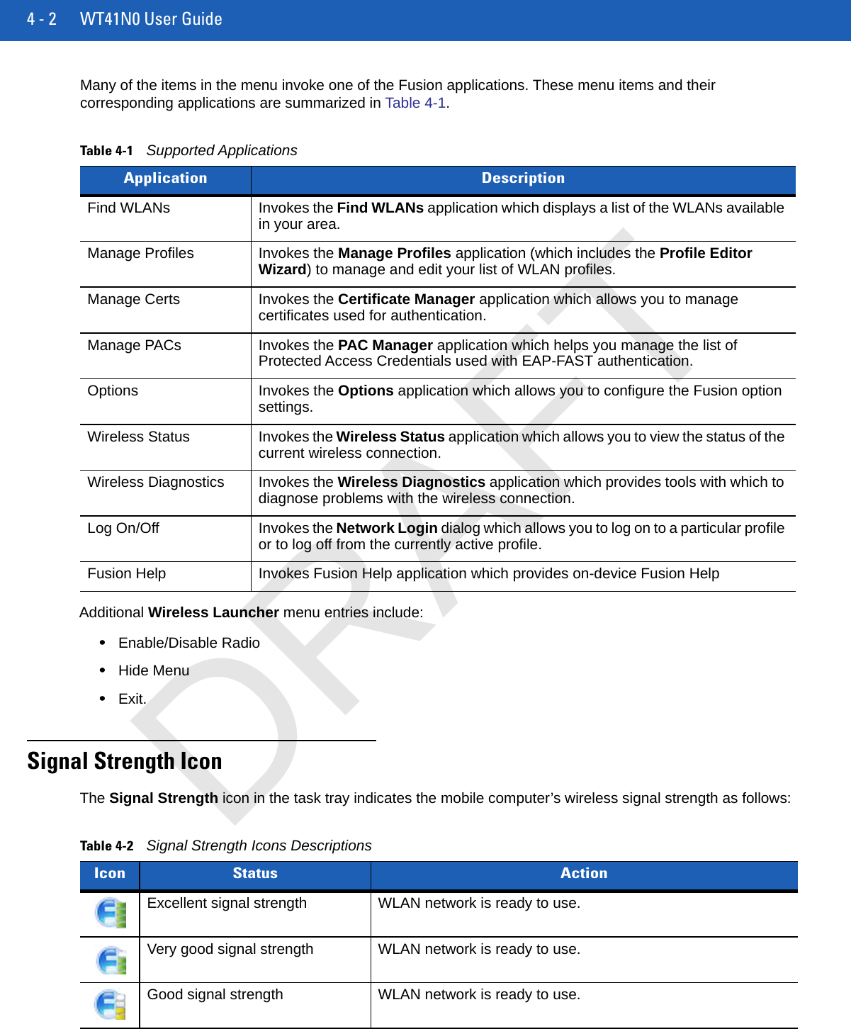
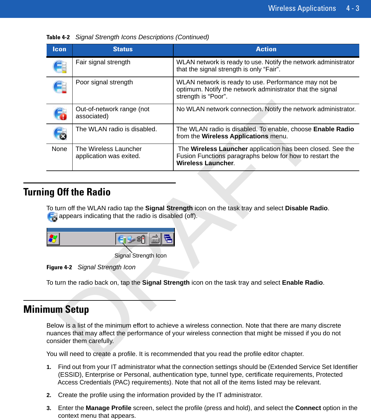
Blue - Orange - 3Blue - Orange - 3\(Backslash) Blue - Orange - 4Blue - Orange - 4`(apostrophe) Blue - Orange - 5Blue - Orange - 5,(comma) Blue - Orange - 6Blue - Orange - 6Table 2-3Two-color Alphanumeric Keypad Descriptions (Continued)Key DescriptionDRAFT
2 - 6 WT41N0 User Guide.(period) Blue - Orange - 7 or Orange - TABBlue - Orange - 7;(semi-colon) Blue - Orange - 8Blue - Orange - 8=(equal sign) Blue - Orange - 9Blue - Orange - 9-(dash) Blue - Orange - Tab Blue - Orange - Tab!(exclamation point) Shift - 1 Shift - 1@(at sign) Shift - 2 Shift - 2#(Pound sign) Shift - 3 Shift - 3$(dollar sign) Shift - 4 Shift - 4%(percent sign) Shift - 5 Shift - 5^(carat) Shift - 6 Shift - 6&(ampersand) Shift - 7 Shift - 7*(asterisk) Shift - 8 Shift - 8((open parenthesis) Shift - 9 Shift - 9)(close parenthesis) Shift - 0 Shift - 0‘(single quote) Blue - Orange - 1Blue - Orange - 1“(double quote) Shift - Blue - Orange - 1 Shift - Blue - Orange - 1?(question mark) Shift - Blue - Orange - 0 Shift - Blue - Orange - 0{(open curly bracket) Shift - Blue - Orange - 2 Shift - Blue - Orange - 2}(close curly bracket) Shift - Blue - Orange - 3 Shift - Blue - Orange - 3Table 2-4Special Character Generation Map  (Continued)Special Character Two-color Keypad Triple-tap KeypadDRAFT
Using the Wearable Terminal 2 - 7Voice Only KeypadThe voice only keypad contains three programmable function keys.Figure 2-5Voice Only Keypad|(pipe) Shift - Blue - Orange - 4 Shift - Blue - Orange - 4~(tilde) Shift - Blue - Orange - 5 Shift - Blue - Orange - 5<(less than sign) Shift - Blue - Orange - 6 Shift - Blue - Orange - 6>(greater than sign) Shift - Blue - Orange - 7 Shift - Blue - Orange - 7:(colon) Shift - Blue - Orange - 8 Shift - Blue - Orange - 8+(plus sign) Shift - Blue - Orange - 9 Shift - Blue - Orange - 9_ (underscore) Shift - Blue - Orange - Tab Shift - Blue - Orange - TabTable 2-4Special Character Generation Map  (Continued)Special Character Two-color Keypad Triple-tap KeypadDRAFT
2 - 8 WT41N0 User GuideDisplayThe wearable terminal is factory installed with the Windows CE 7.0 operating system. When the wearable terminal starts, it automatically launches the Start Up application.App Launcher WindowThe App Launcher window allows the user to launch specific applications by using the keypad. Either scroll up and down using the arrow keys and select Enter to select an item or press the numeric key associated with the item. If the App Launcher window is closed, launch the App Launcher window by selecting Start > Programs > AppLauncher.Figure 2-6Start-up WindowNOTE To view the software versions on the Voice Only WT41N0, the Voice Only WT41N0 must be connected to a host computer running remote desktop software. See the WT41N0 Integrator Guide for more information.NOTE A customer specific application can be configured to automatically start-up and the Windows CE 7.0 desktop and Start Up application might not be visible or accessible.NOTE App Launcher window does not automatically launch on the Voice Only WT41N0.Table 2-5Start Up Item Descriptions Item LaunchNumber DescriptionRapid Deployment Client 1 Launches the Rapid Deployment application. Refer to the WT41N0 Integrator Guide for more information.Internet Explorer 2 Launches the Microsoft Pocket Internet Explorer application.Utilities folder 3 Opens a sub-window that contains utilities, such as: Control Panel, File Explorer, BT Connect and test applications. For more information on the Control Panel and File Explorer.Demo Apps 4 Opens a sub-window that contains sample demonstration applications.Exit 5 Closes the Start Up window.DRAFT
Using the Wearable Terminal 2 - 9Windows CE 7.0 DesktopThe following paragraphs describe the Windows CE 7.0 desktop. Depending upon the customer’s configuration of the wearable terminal, the desktop may not be available.Status IconsThe Taskbar at the bottom of the window displays the active programs, current time, battery status and communication status.Figure 2-7TaskbarStatus icons are shown in the taskbar to indicate present status of the wearable terminal.Table 2-6Status Icons StatusIcon DescriptionIndicates the current time. The clock can be toggled on and off. Select Start > Settings > Control Panel > Task and Start Menu.This icon indicates that the main battery is charging or that the wearable terminal is operating on external power.Indicates that the battery is fully charged and the wearable terminal is running on external power.This icon is displayed when the memory backup battery level is low. Charge the battery.This icon indicates that the battery is fully charged (100% charged).The battery status icons provide the battery status in 10% increments from 10% to 100%.This displays when the terminal is connected to a host computer with ActiveSync.Start Button Open ProgramStatus IconsDesktop ButtonClockDRAFT
2 - 10 WT41N0 User GuidePrograms MenuFrom the Start menu, tap Programs to open the Programs menu. The programs installed on the wearable terminal with Windows CE display in the Programs menu.Wireless connection status icon. Indicates WLAN signal strength.Bluetooth radio is on.Bluetooth radio is off.Bluetooth radio is connected to another Bluetooth device.Indicates that the SHIFT key is selected.Indicates that the Blue key is selected.Indicates that the CTRL key is selected.Indicates that the ALT key is selected.Indicates that the Orange key is selected.Indicates that the Gray key is selected.Indicates that the Motorola Remote Control software is connected to the wearable terminal.Table 2-6Status Icons (Continued)StatusIcon DescriptionNOTE For the non-touch configurations, see ????? for instruction on navigating using the navigation pad.DRAFT
Using the Wearable Terminal 2 - 11Table 2-7Applications in the Programs MenuIcon Description Icon DescriptionAppLauncher: BTScannerCtlPanel:Internet ExplorerMicrosoft WordPadMotoBTUIFusion Folder: Open the Wireless Companion folder. See Chapter 5, Wireless Applications for more information.Command Prompt: Opens a DOS command prompt window. CtlPanel: View and change wearable terminal settings such as: Scanner Parameters, Display Settings, Audio Settings, Printer Settings, Date and Time Settings, Touch Screen Settings, etc.MSP Agent: Interacts with MSP agents to collect monitoring and asset information to enable the configuration, provisioning, monitoring and troubleshooting of the wearable terminal. Refer to the WT41N0 Integrator Guide for more information.Rapid Deployment Client: Facilitates software downloads from a Mobility Services Platform Console FTP server to the wearable terminal. Refer to the WT41N0 Integrator Guide for more information.Samples: Opens the Sample Applications window, when installed. Music PlayerRemote Desktop ConnectionWarmBoot: Warm boots the wearable terminal. Windows Explorer: Organize and manage files on your device.DRAFT
2 - 12 WT41N0 User GuideControl PanelTable 2-8 lists the applications in the Control Panel.Table 2-8Programs on the Control PanelIcon Description Icon DescriptionBacklight: Adjust the backlight brightness and power settings. Bluetooth Device Properties: Launch the Bluetooth application.Certificates: See information about certificates installed on the wearable terminal.DataWedge: Sample scanning application. See Chapter 3, Data Capture for more information.Date/Time: Change date, time and time zone information. Dialing: Set dialing properties for modem communication and change telephony settings.Display: Change desktop background, appearance, backlight and brightness. Input Panel: Switch input methods and set input options.Internet Options: IST Settings: Keyboard: Change keyboard repeat delay and rate. Keylight: Mouse: Adjust double-click sensitivity for both the speed and timing. Network and Dial-up Connections: Connect to other computers, networks and the Internet using a modem.Owner: Change owner’s personal profiles.Password: Set a password for the wearable terminal.PC Connection: Change settings for connectivity of a host computer. Power: View and control wearable terminal power settings.Regional Settings: Change how numbers, currencies, dates and times appear.Remove Programs: Remove programs installed on the wearable terminal.Stylus: Calibrate the touch screen and adjust double-tap timing. System: View system information and change memory settings.System Info: View information on the wearable terminal’s system components.USBConfig: Configure the wearable terminal USB port.Volume & Sounds: Select the type of actions for which to hear sounds and customize notifications for different events.DRAFT
Using the Wearable Terminal 2 - 13Using the Keypad to Navigate ApplicationsOn wearable computers without touch-enabled screens navigation and control of an application is performed using the keypad.Key CombinationsThe wearable terminal uses special key combinations to easily navigate applications. Table 2-9 lists the key combinations required to perform various application navigation and control functions.Throughout this guide you will be instructed to select an item. You must use a key combination to select that item. For example: To perform:“Select Start > Programs > Windows Explorer”1. Press CTRL and then ESC to open the Start menu.2. Press the up arrow until the Programs item is highlighted.3. Press the Blue key and the down arrow to open the Programs sub-menu.4. Press the down arrow until Windows Explorer is highlighted.5. Press ENTER key to launch Windows Explorer.Selecting ItemsWhen using the navigation keys to perform tasks in an application, the active item is highlighted using either a color background and/or a dashed box.NOTE Not available on the Voice Only configuration.Table 2-9Key Combinations Action Key CombinationAccess the Start menu on the taskbarCTRL - ESCSwitch fields within an applicationTABClose windows or cancel operations on some applicationsESC or ALT - F4Access the Task ManagerALT - TABSwitches to the next window or desktopALT - ESCAccess a menu bar in an applicationALT - ALTPress a button or select a check box in an applicationTAB until the item is highlighted then SPACE.Display a pop-up context menuALT - ENTERDRAFT
2 - 14 WT41N0 User GuideFigure 2-8Highlighted ItemsNavigating MenusMost applications have drop-down menus to perform specific functions. Use the key combination ALT - ALT to open a menu. Once the menu is open, use the up and down navigation keys to move up and down the menu and use the left and right navigation keys to move to the next menu item or open a sub-menu. When moving through a menu, items are highlighted. Once an item is highlighted, press the ENTER key to select that item.Figure 2-9Navigating MenusNavigating TabsSome applications contain multiple pages with tabs indicating each page. Use the TAB key to highlight the tab. A dashed box appears around the tab name. Use the left and right navigation keys to move to the next or previous tab.Figure 2-10Navigating TabsNavigating FieldsTo navigate from one field to another, press the TAB key. Repeated pressing of the TAB key cycles the highlighted cursor through the fields in the window.Highlighted ItemSelected TabDRAFT
Using the Wearable Terminal 2 - 15Selecting Checkboxes and Radio ButtonsTo select or deselect checkboxes and radio buttons press the TAB key until the field is highlighted. Press ALT - BKSP (SPACE) to select or deselect the checkbox or radio button.Figure 2-11Selecting a Checkbox or Radio ButtonSelecting Items in a ListUse a combination of key sequences to select items in a folder or list.To select continuous items in a folder or list:1. Open the folder or list.2. Use the scroll keys to move to the first item to select.3. Press SHIFT - scroll key (either up or down) to select the next item.4. Repeat the SHIFT - scroll key combination to select remaining items.5. Perform the desired function.To select multiple items in a folder or list:1. Open the folder or list.2. Use the scroll keys to move to the first item.3. Press CTRL - scroll key to move within the list. The item name is outlined.4. Repeat step 3 to move to the desired item.5. Press SPACE to highlight the item.6. Repeat steps 3 through 5 until all items are selected.7. Perform the desired function.Screen CalibrationTo calibrate the touch screen so the cursor on the touch screen aligns with screen taps:1. Press Start > Settings > Control Panel > Stylus icon > Calibration tab > Recalibrate button.2. Carefully press and briefly hold on the center of the Calibration screen target. Repeat the procedure as the target moves and stops at different locations on the screen. This enters the new calibration settings.Highlighted CheckboxRadio ButtonsNOTE Not available on the Voice Only and non-touch configurations.DRAFT
2 - 16 WT41N0 User Guide Figure 2-12Calibration Screen3. Once all of the new calibration settings are input, tap the screen or press the ENTER button to save the new calibration settings. Press ESC to discard the new calibration settings.Special Character KeypadThe wearable terminal contains an on-screen Special Character keypad that allows users to enter alphanumeric and special characters. The keypad looks and functions like a standard keyboard.To display the Special Character keypad, press the   key on the keyboard.Figure 2-13Special Character Keypad - Alphanumeric LayerUse the arrow keys on the keyboard to move the yellow box to highlight a key on the Special Character keypad. The arrow keys wrap to the next row or column as you navigate with the keys.To select a character, press the Enter key on the wearable terminal.If the Enter or arrow keys need to be used by the application instead of the Special Character keypad, press Esc followed by the arrow or Enter key. This sends the key to the application instead of the Special Character keypad.Press the ABC key on the Special Character keypad to switch between the alphanumeric layer and the character layer.Calibration Screen Confirm Calibration ScreenNOTE The Special Character Keypad is only available on non-touch screen configurations with a display.DRAFT
Using the Wearable Terminal 2 - 17Figure 2-14Special Character Keyboard - Character LayerNavigate the keypad in the same manner as described above. To return to the alphanumeric layer, press the CH key on the keypad.Pressing CAP or SH switches the keypad to the upper case alphanumeric keypad.Figure 2-15Special Character Keyboard in upper case Alphanumeric ModePress the   key to close the Special Character keypad.Resetting the Wearable TerminalThere are two types of resets, warm boot and cold boot. A warm boot restarts the wearable terminal by closing all running programs.A cold boot also restarts the wearable terminal, but erases all stored records and entries in RAM. Data saved in flash memory or a memory card is not lost. In addition it returns formats, preferences and other settings to the factory default settings.Perform a warm boot first. This restarts the wearable terminal and saves all stored records and entries. If the wearable terminal still does not respond, perform a cold boot.Performing a Warm BootHold down the Power button for approximately five seconds. As soon as the wearable terminal starts to perform a warm boot release the Power button.DRAFT
2 - 18 WT41N0 User GuidePerforming a Cold BootA cold boot restarts the wearable terminal and erases all user stored records and entries that are not saved in flash memory (Application and Platform folders). Never perform a cold boot unless a warm boot does not solve the problem.To perform a cold boot on a WT41N0 press and simultaneously hold the 1, 9 and Power button. Do not hold down any other keys or buttons. The wearable terminal initializes.To perform a cold boot on a Voice Only WT41N0 press and simultaneously hold the P1 and P2 keys and the Power button. The wearable terminal initializes.NOTE Any data previously synchronized with a computer can be restored during the next ActiveSync operation.DRAFT
Using the Wearable Terminal 2 - 19Waking the Wearable TerminalThe wake up conditions define what actions wake up the wearable terminal after it has gone into suspend mode. The wearable terminal can go into suspend mode by either pressing the Power button or automatically by control panel time-out settings. These settings are configurable and the factory default settings are shown in Table 2-10.Battery HealthThe health of the battery can be viewed on the wearable terminal Power applet. Select Start > Settings > Control Panel > Power icon > BatteryMgmt tab.For information on changing the Battery Usage Threshold, refer to the WT41N0 Integrator Guide.Table 2-10Wakeup Default Settings Condition for Wakeup Power Button Automatic Time-outAC power is applied. No YesWearable terminal is inserted into a cradle. No YesWearable terminal is removed from a cradle. No YesWearable terminal is connected to a USB device. No YesWearable terminal is disconnected from a USB device. No YesA key is pressed. No YesAn attached scanner is triggered. No YesWireless LAN activity is detected. No NoA headset is connected to the wearable terminal. No YesScreen Touch (only on touch screen configurations) No NoNOTE If the battery is removed and replaced, the only way to wake up the terminal is by pressing the Power button.Table 2-11BatteryMgmt Window Item DescriptionState of Health Indicates the current state of the battery (Healthy or Unhealthy).Battery Usage Indicator Indicates the usage of the battery.Battery Usage Threshold Indicates the usage indicator threshold.Battery Serial # Displays the serial number of the battery.DRAFT
2 - 20 WT41N0 User GuideDRAFT
CHAPTER 3 DATA CAPTUREIntroductionThe wearable terminal can be used with the following optional data capture accessories:•RS309 laser scanner•RS409 laser scanner•RS419 laser scanner•RS507 Hands-free imager.Laser ScanningWearable terminals with an optional RS309, RS409 or RS419 laser scanner have the following features:•Reading of a variety of bar code symbologies, including the most popular linear, postal, and 1D code types.•Advanced intuitive laser aiming for easy point-and-shoot operation.Scanning ConsiderationsTypically, scanning is a simple matter of aim, scan/decode and a few quick trial efforts master it. However, two important considerations can be used to optimize any scanning performance:•RangeAny scanning device decodes well over a particular working range — minimum and maximum distances from the bar code. This range varies according to bar code density and scanning device optics.Scanning within range brings quick and constant decodes; scanning too close or too far away prevents decodes. Move the scanner closer and further away to find the right working range for the bar codes being scanned. However, the situation is complicated by the availability of various integrated scanning modules. The best way to specify the appropriate working range per bar code density is through a chart called a decode zone for each scan module. A decode zone simply plots working range as a function of minimum element widths of bar code symbols.•AngleDRAFT
3 - 2 WT41N0 User GuideScanning angle is important for promoting quick decodes. When laser beams reflect directly back into the scanner from the bar code, this specular reflection can “blind” the scanner.To avoid this, scan the bar code so that the beam does not bounce directly back. But don’t scan at too sharp an angle; the scanner needs to collect scattered reflections from the scan to make a successful decode. Practice quickly shows what tolerances to work within.Scanning Bar Codes1. Ensure that a scan enabled application is loaded on the wearable terminal.2. Aim the scan exit window at the bar code.3. Press the trigger.•Ensure the red scan beam covers the entire bar code. The red scan LED lights to indicate that the laser is on. The green scan LED lights. An audible beep might sound, if the application determines, to indicate the bar code was decoded successfully.Figure 3-1Laser Scanner Aiming Pattern4. Release the trigger.Scanning TipsOptimal scanning distance varies with bar code density and scanner optics.•Hold the scanner farther away for larger symbols.•Move the scanner closer for symbols with bars that are close together.Scan LED IndicatorThe LED on the scanner provides a visual indication of the scan status.NOTE Contact the Symbol Support Center if chronic scanning difficulties develop. Decoding of properly printed bar codes should be quick and effortless. NOTE Imager decoding usually occurs instantaneously. The wearable terminal repeats the steps required to take a digital picture (image) of a poor or difficult bar code, as long as the trigger remains pulled.NOTE Scanning procedures depend on the application and wearable terminal configuration. An application may use different scanning procedures from the one listed above. Table 3-1Scan LED Indicators LED Status IndicationOff Not scanning.Solid Red Laser enabled, scanning in process.Solid Green Successful decode.DRAFT
Data Capture 3 - 3ImagingThe wearable terminal with an optional RS507 imager has the following features:•Omnidirectional (360°) reading of a variety of bar code symbologies, including the most popular linear, postal, PDF417, and 2D matrix code types.•The ability to capture and download images to a host for a variety of imaging applications.•Advanced intuitive laser aiming for easy point-and-shoot operation.The imager uses digital camera technology to take a digital picture of a bar code, stores the resulting image in its memory, and executes state-of-the-art software decoding algorithms to extract the data from the image.Operational ModesThe wearable terminal with optional RS507 imager supports three modes of operation, listed below. Activate each mode pressing the Scan button.•Decode Mode: In this mode, the RS507 attempts to locate and decode enabled bar codes within its field of view. The imager remains in this mode as long as you hold the scan button, or until it decodes a bar code.•Pick List Mode: This mode allows you to selectively decode a bar code when more than one bar code is in the RS507’s field of view. To accomplish this, move the aiming crosshair center dot over the required bar code to decode only that bar code. This feature is ideal for pick lists containing multiple bar codes and manufacturing or transport labels containing more than one bar code type (either 1D or 2D).•Image Capture Mode: Use this mode to capture an image within the RS507’s field of view. This is useful for capturing signatures or images of items like damaged boxes.Imager Scanning1. Ensure that a scan-enabled application is loaded on the wearable terminal.2. Press and hold the scan button.The red laser aiming pattern turns on to assist in aiming. Ensure the cross-hair is on top of the bar code.The Decode LED lights red to indicate that scanning is in process, then lights green and a beep sounds, by default, to indicate the bar code was decoded successfully. Note that when the RS507 is in Pick List Mode, the imager does not decode the bar code until the crosshair center dot touches the bar code.NOTE To enable Pick List Mode, download the Control Panel applet from the Support Central web site at http://www.motorola.com/enterprisemobility/support. Pick List can also be set in an application using a API command.DRAFT
3 - 4 WT41N0 User GuideFigure 3-2Imager Aiming PatternFigure 3-3Pick List Mode with Multiple Bar Codes3. Release the scan button.NOTE Imager decoding usually occurs instantaneously. The RS507 repeats the steps required to take a digital picture (image) of a poor or difficult bar code as long as the scan button remains pressed.DRAFT
CHAPTER 4 WIRELESS APPLICATIONSIntroductionWireless Local Area Networks (LANs) allow mobile computers to communicate wirelessly and send captured data to a host device in real time. Before using the wearable terminal on a WLAN, the facility must be set up with the required hardware to run the wireless LAN and the wearable terminal must be configured. Refer to the documentation provided with the access points (APs) for instructions on setting up the hardware.To configure the wearable terminal, a set of wireless applications provide the tools to configure and test the wireless radio in the wearable terminal. Refer to the Wireless Fusion Enterprise Mobility Suite User Guide for Version X1.01 for information on configuring wireless profiles. Go to http://supportcentral.motorola.com for the latest version of this guide. See Software Versions on page x to determine the Fusion version on the wearable terminal.Tap the Signal Strength icon to display the Wireless Launcher menu.Figure 4-1Wireless Launcher MenuNOTE 802.11d is enabled by default. When enabled, the AP must be configured the same in order to connect.Signal Strength IconDRAFT
4 - 2 WT41N0 User GuideMany of the items in the menu invoke one of the Fusion applications. These menu items and their corresponding applications are summarized in Table 4-1.Additional Wireless Launcher menu entries include:•Enable/Disable Radio•Hide Menu•Exit.Signal Strength IconThe Signal Strength icon in the task tray indicates the mobile computer’s wireless signal strength as follows:Table 4-1Supported Applications Application DescriptionFind WLANs Invokes the Find WLANs application which displays a list of the WLANs available in your area.Manage Profiles Invokes the Manage Profiles application (which includes the Profile Editor Wizard) to manage and edit your list of WLAN profiles.Manage Certs Invokes the Certificate Manager application which allows you to manage certificates used for authentication.Manage PACs Invokes the PAC Manager application which helps you manage the list of Protected Access Credentials used with EAP-FAST authentication.Options Invokes the Options application which allows you to configure the Fusion option settings.Wireless Status Invokes the Wireless Status application which allows you to view the status of the current wireless connection.Wireless Diagnostics Invokes the Wireless Diagnostics application which provides tools with which to diagnose problems with the wireless connection.Log On/Off Invokes the Network Login dialog which allows you to log on to a particular profile or to log off from the currently active profile.Fusion Help Invokes Fusion Help application which provides on-device Fusion HelpTable 4-2Signal Strength Icons Descriptions Icon Status ActionExcellent signal strength WLAN network is ready to use.Very good signal strength WLAN network is ready to use.Good signal strength WLAN network is ready to use.DRAFT
Wireless Applications 4 - 3Turning Off the RadioTo turn off the WLAN radio tap the Signal Strength icon on the task tray and select Disable Radio. appears indicating that the radio is disabled (off).Figure 4-2Signal Strength IconTo turn the radio back on, tap the Signal Strength icon on the task tray and select Enable Radio.Minimum SetupBelow is a list of the minimum effort to achieve a wireless connection. Note that there are many discrete nuances that may affect the performance of your wireless connection that might be missed if you do not consider them carefully.You will need to create a profile. It is recommended that you read the profile editor chapter.1. Find out from your IT administrator what the connection settings should be (Extended Service Set Identifier (ESSID), Enterprise or Personal, authentication type, tunnel type, certificate requirements, Protected Access Credentials (PAC) requirements). Note that not all of the items listed may be relevant.2. Create the profile using the information provided by the IT administrator.3. Enter the Manage Profile screen, select the profile (press and hold), and select the Connect option in the context menu that appears.Fair signal strength WLAN network is ready to use. Notify the network administrator that the signal strength is only “Fair”.Poor signal strength WLAN network is ready to use. Performance may not be optimum. Notify the network administrator that the signal strength is “Poor”.Out-of-network range (not associated) No WLAN network connection. Notify the network administrator.The WLAN radio is disabled. The WLAN radio is disabled. To enable, choose Enable Radio from the Wireless Applications menu.None The Wireless Launcher application was exited.  The Wireless Launcher application has been closed. See the Fusion Functions paragraphs below for how to restart the Wireless Launcher.Table 4-2Signal Strength Icons Descriptions (Continued)Icon Status ActionSignal Strength IconDRAFT
4 - 4 WT41N0 User GuideDRAFT

Navigation menu