Zebra Technologies WT41N0 Wearable Terminal User Manual Part 2
Zebra Technologies Corporation Wearable Terminal Part 2
UserManual.wiki
>
Zebra Technologies
>
WT41N0 User Manual
>
User Manual Part 2
Contents
1.
User Manual Part 1
2.
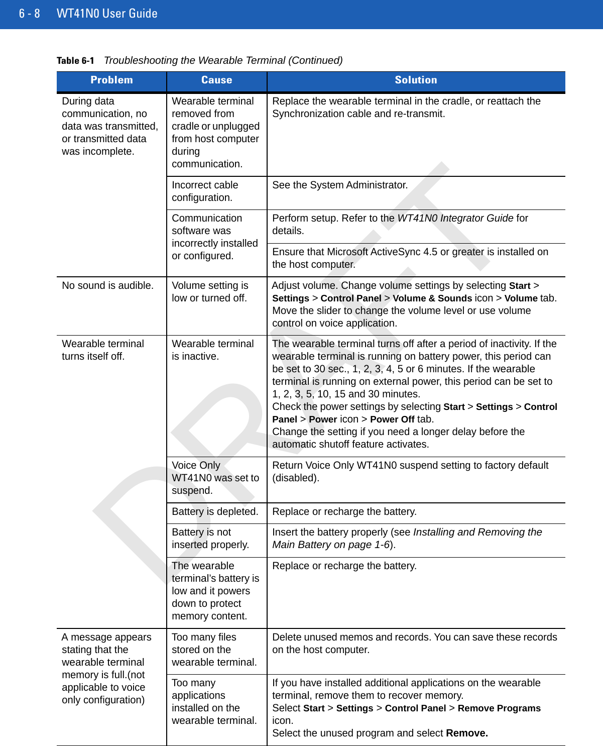
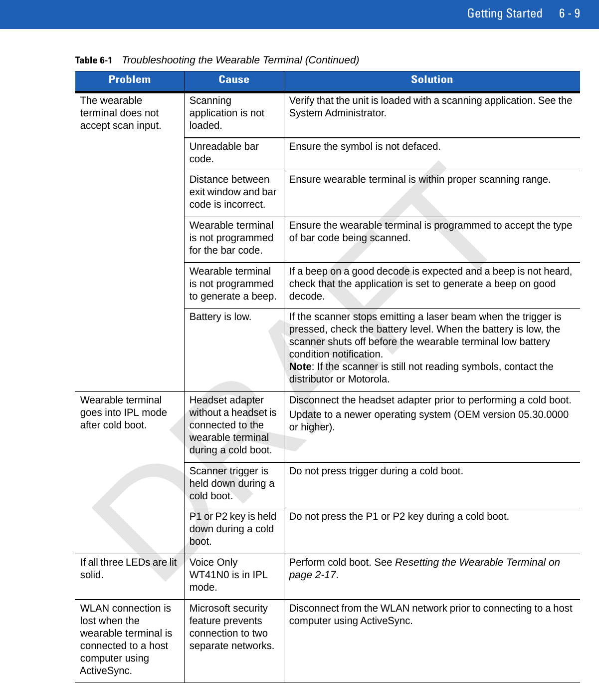
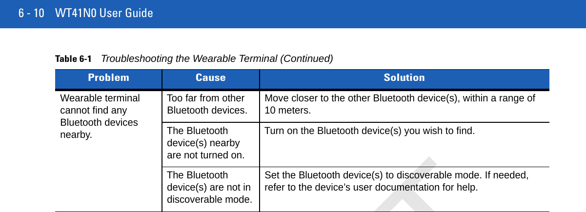
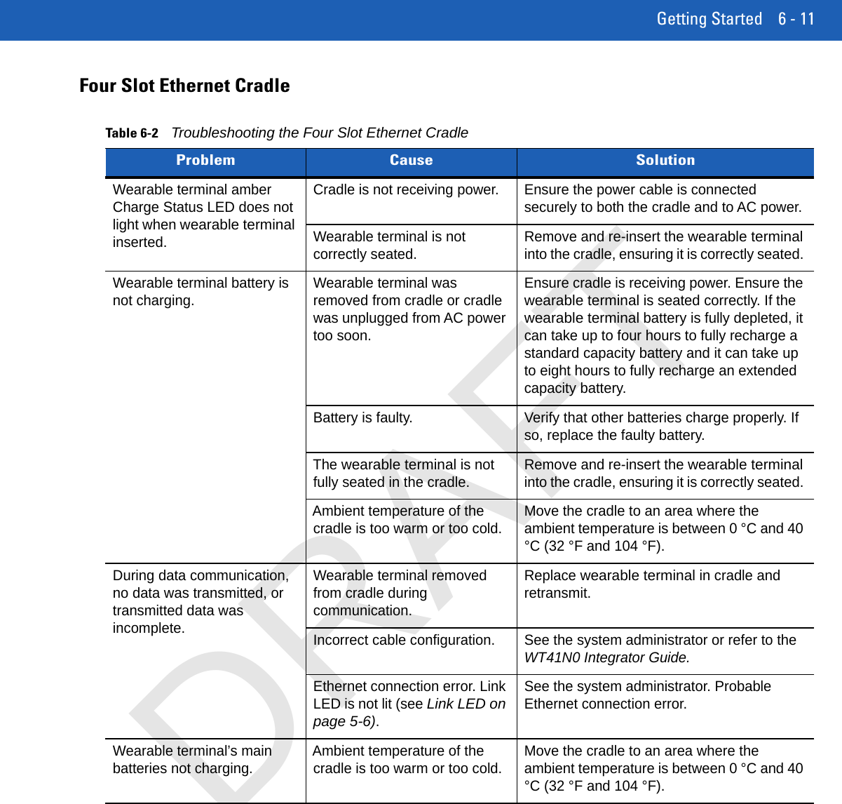
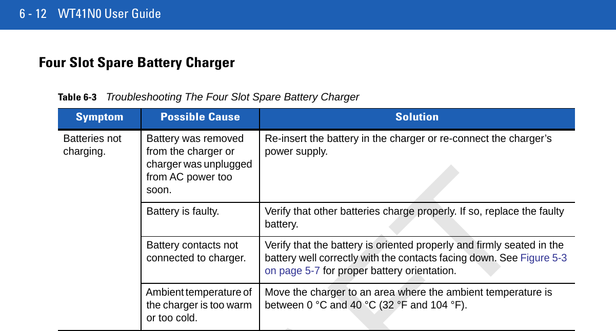
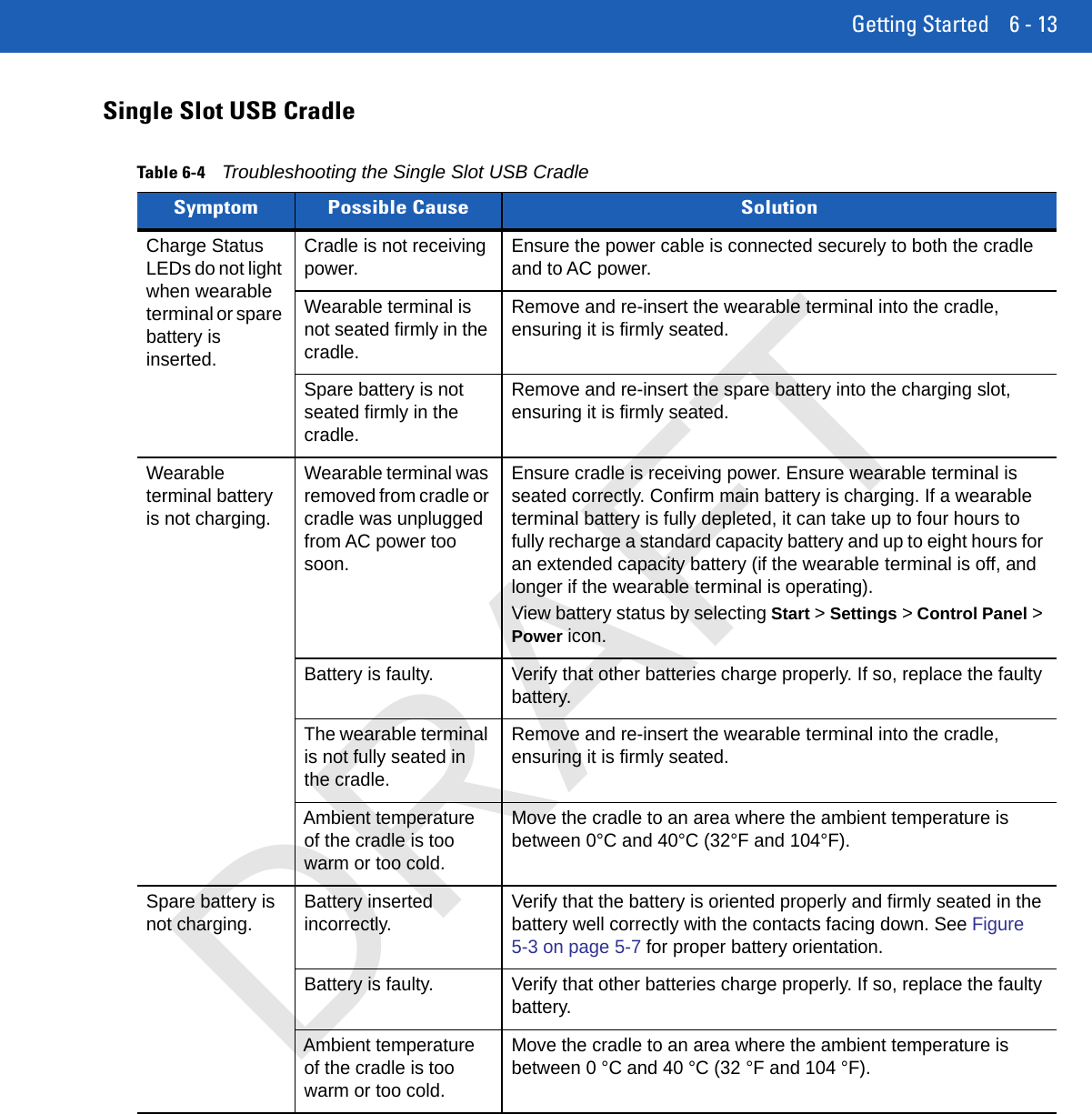
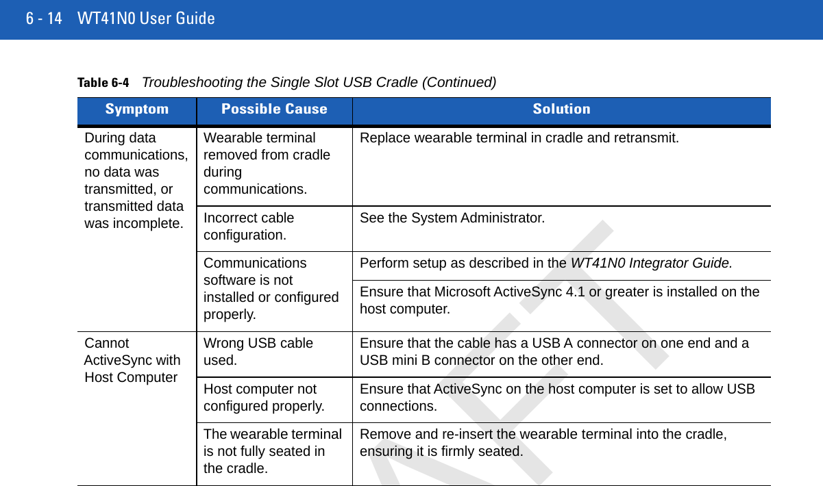
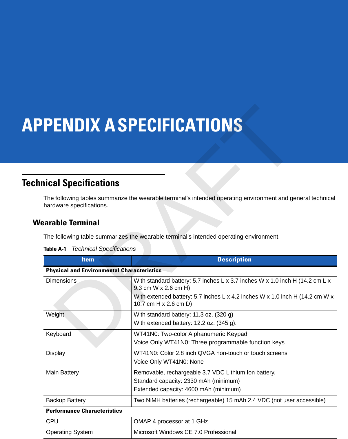
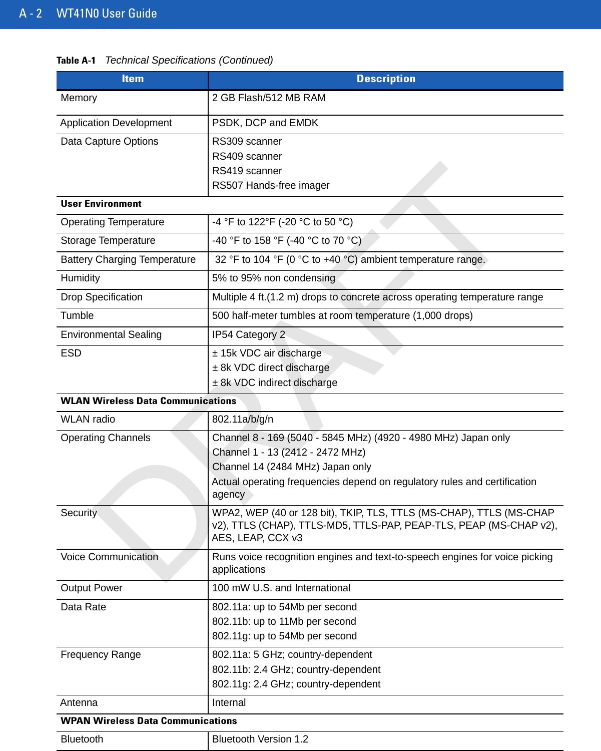
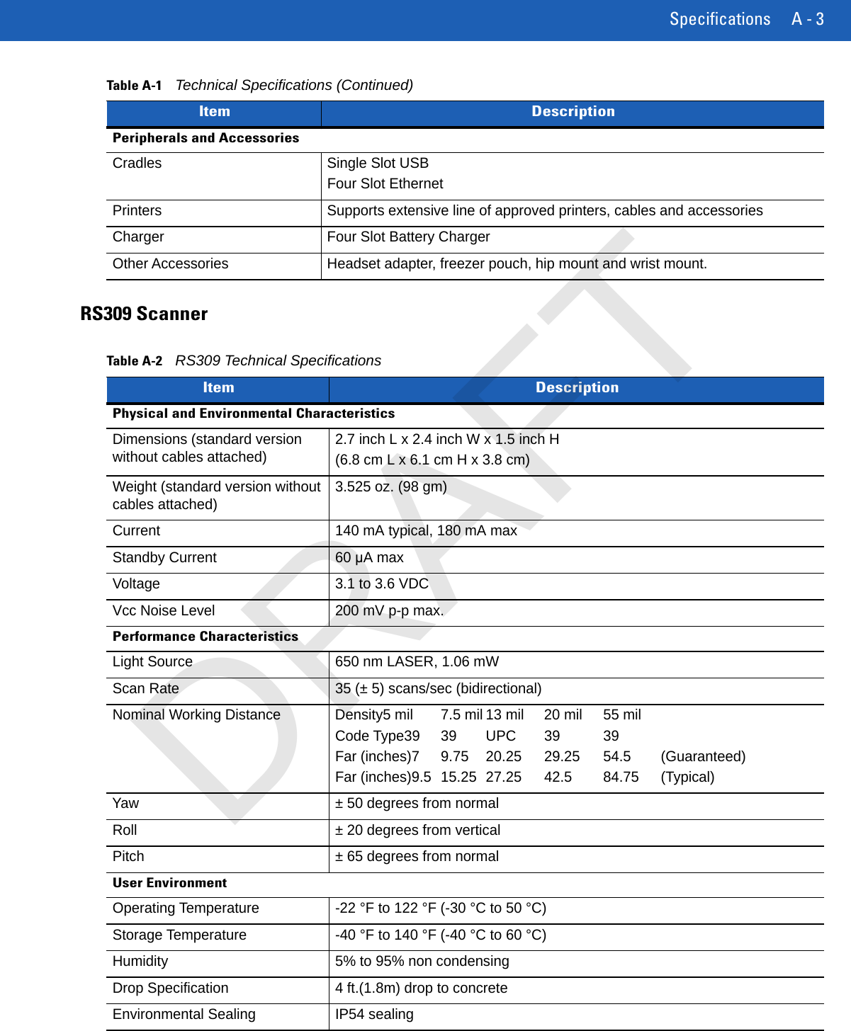
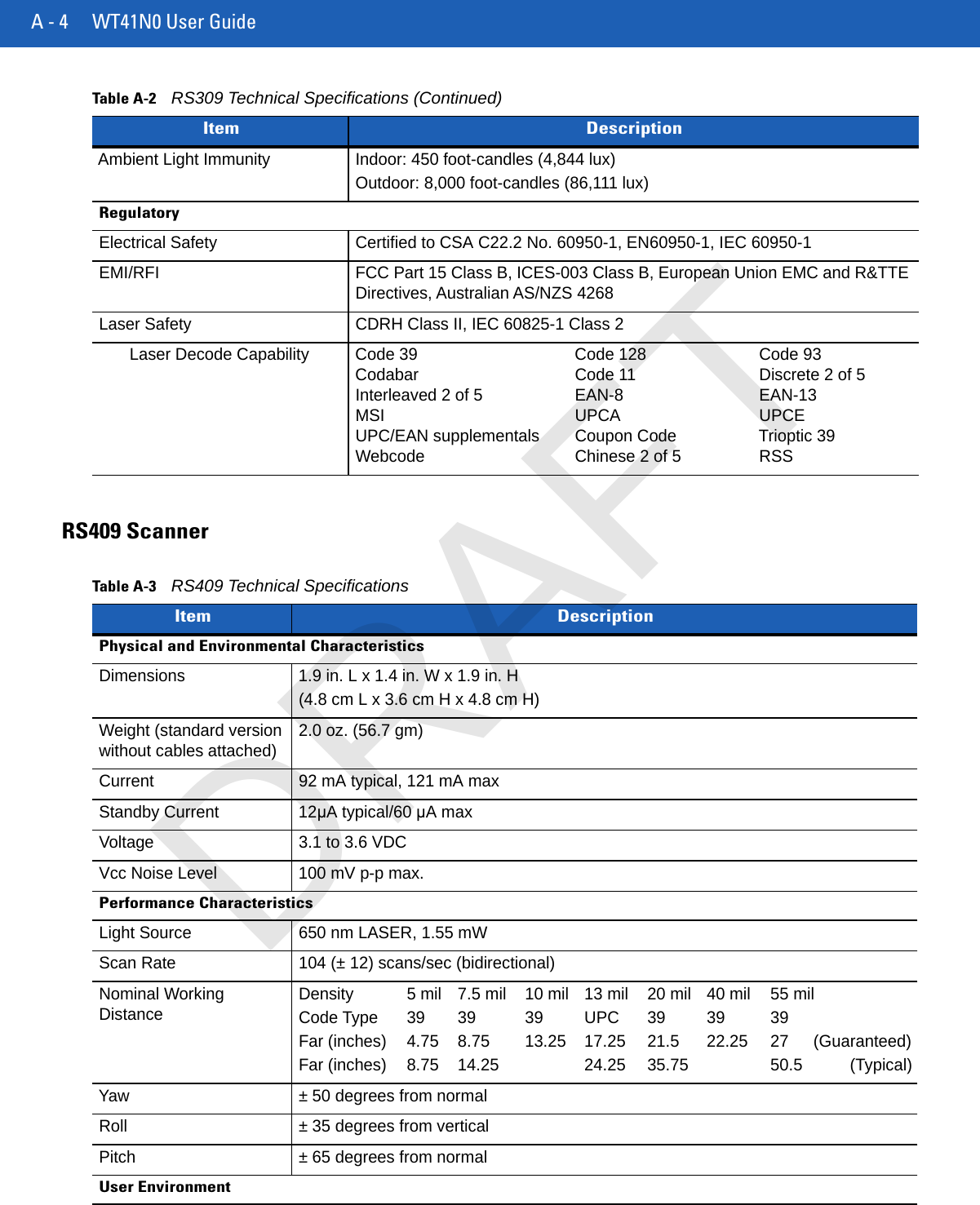
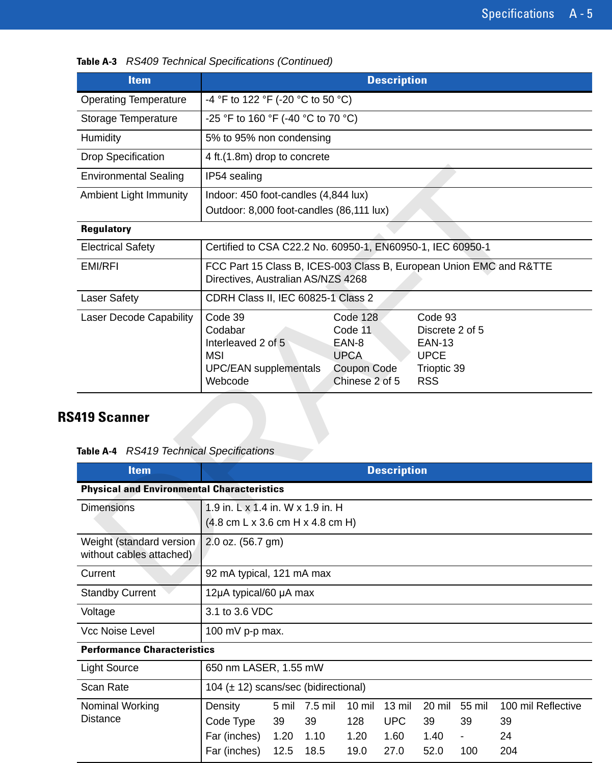
User Manual Part 2
3.
User Manual Statements
4.
User Manaul.pdf
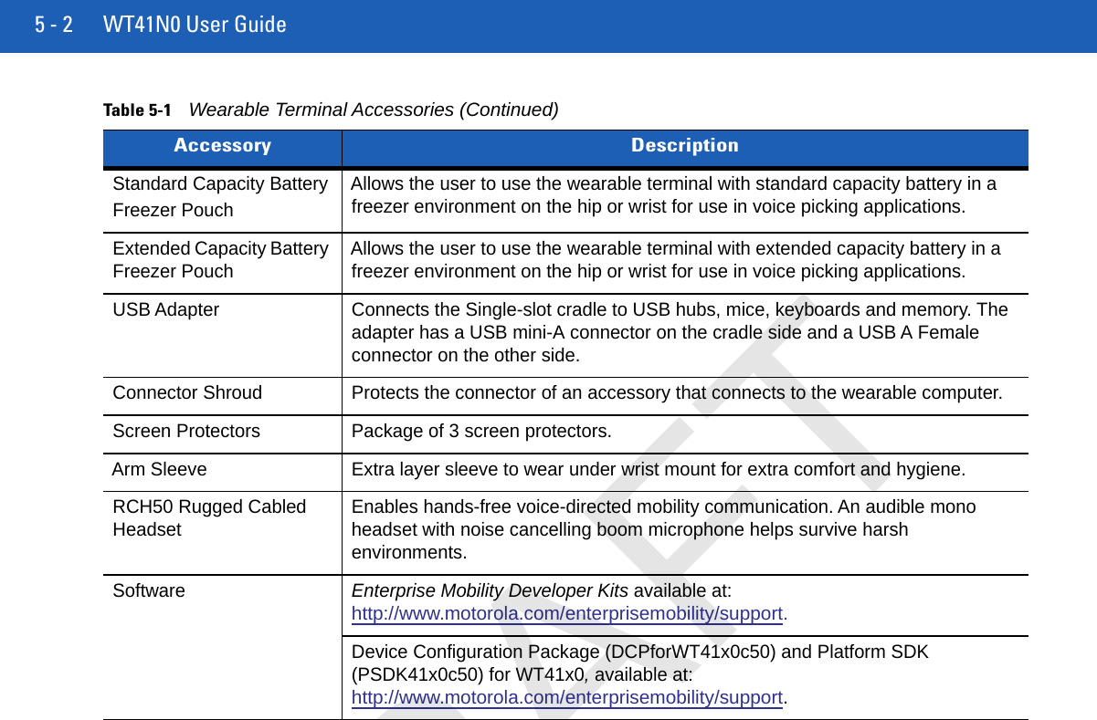
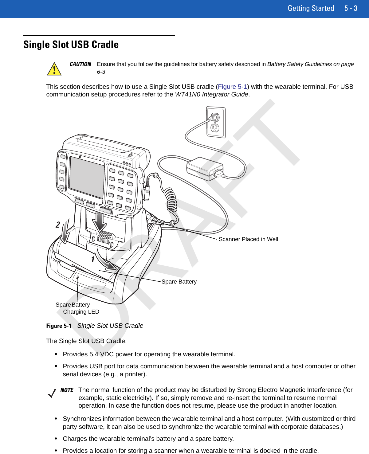
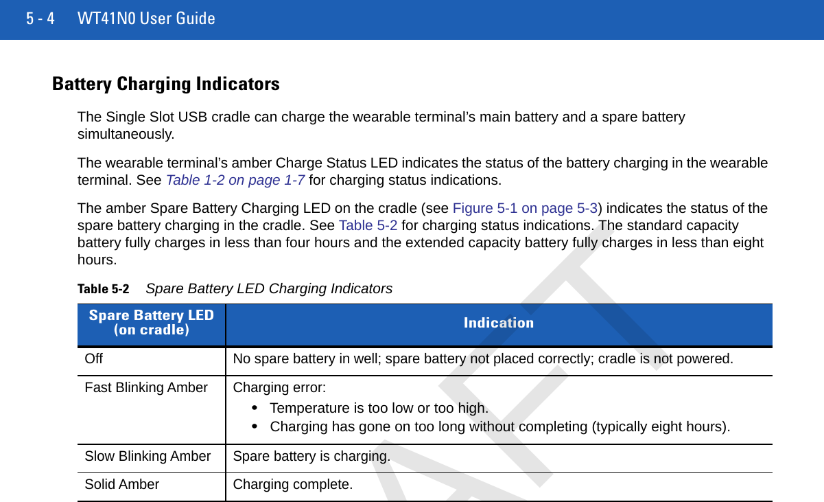
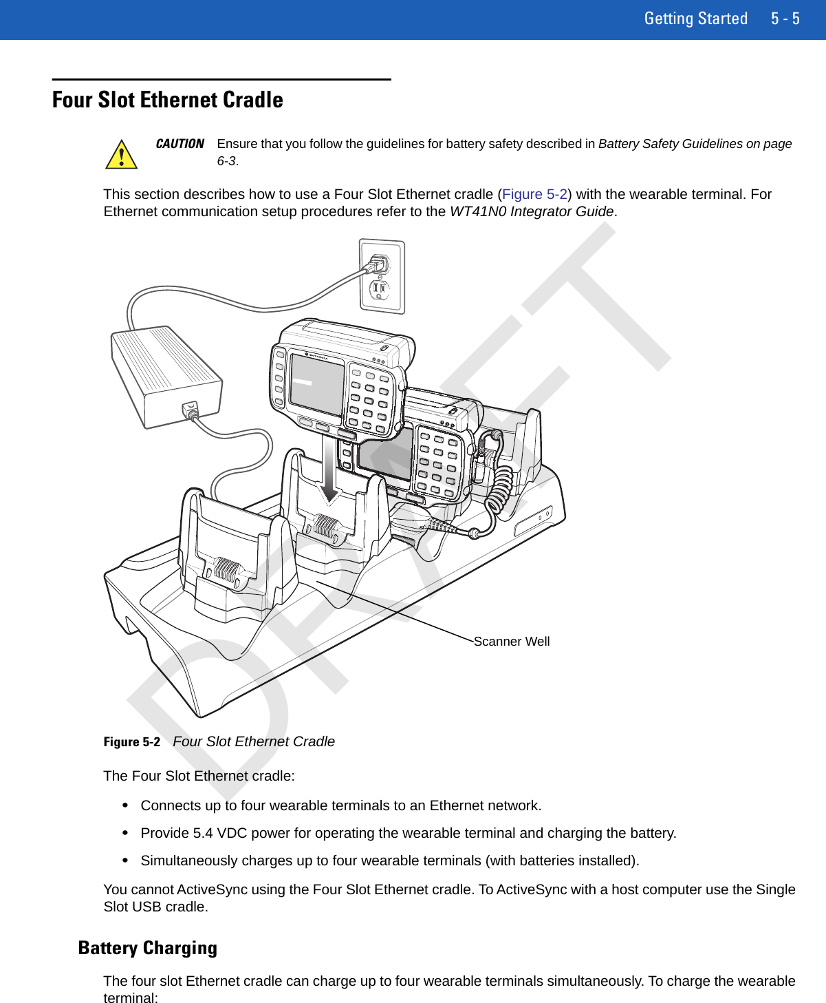
User Manual Part 2
Navigation menu
Upload a User Manual
Namespaces
Wiki Guide
HTML
PDF
Info
Views
User Manual
Discussion / Help
Navigation