Zebra Technologies WT41N0 Wearable Terminal User Manual Part 2
Zebra Technologies Corporation Wearable Terminal Part 2
Contents
- 1. User Manual Part 1
- 2. User Manual Part 2
- 3. User Manual Statements
- 4. User Manaul.pdf
User Manual Part 2

CHAPTER 5 ACCESSORIES
Introduction
The wearable terminal accessories provide a variety of product support capabilities. Accessories include
cradles, cables and scanners. Table 5-1 lists the major accessories available for the wearable terminal:
Table 5-1
Wearable Terminal Accessories
Accessory Description
Single Slot USB Cradle Charges the
wearable terminal
main battery and a spare battery. It also
synchronizes the
wearable terminal
with a host computer through a USB
connection.
Four Slot Ethernet Cradle Charges up to four
wearable terminals
(with main battery installed) and provides
communication through an Ethernet connection.
Four Slot Spare Battery
Charger Charges up to four spare batteries.
RS409 Scanner Provides 1D scanning capability.
RS419 Scanner Provides 1D scanning capability.
RS309 Scanner Provides 1D scanning capability.
RS507 Scanner Provides wired or wireless imaging capability.
Wrist Mount Provides a means for wearing the wearable terminal on the arm for hands-free
applications.
Hip Mount Provides a means for wearing the wearable terminal on a belt for hands-free
applications.
Headset For audio playback/recording during voice-enabled applications.
Headset Adapters Connect an optional headset to the wearable terminal.
Replacement Batteries Standard Capacity Battery: 2330 mAh (minimum)
Extended Capacity Battery: 4600 mAh (minimum)
DRAFT

5 - 2 WT41N0 User Guide
Standard Capacity Battery
Freezer Pouch
Allows the user to use the wearable terminal with standard capacity battery in a
freezer environment on the hip or wrist for use in voice picking applications.
Extended Capacity Battery
Freezer Pouch Allows the user to use the wearable terminal with extended capacity battery in a
freezer environment on the hip or wrist for use in voice picking applications.
USB Adapter Connects the Single-slot cradle to USB hubs, mice, keyboards and memory. The
adapter has a USB mini-A connector on the cradle side and a USB A Female
connector on the other side.
Connector Shroud Protects the connector of an accessory that connects to the wearable computer.
Screen Protectors Package of 3 screen protectors.
Arm Sleeve Extra layer sleeve to wear under wrist mount for extra comfort and hygiene.
RCH50 Rugged Cabled
Headset Enables hands-free voice-directed mobility communication. An audible mono
headset with noise cancelling boom microphone helps survive harsh
environments.
Software Enterprise Mobility Developer Kits available at:
http://www.motorola.com/enterprisemobility/support
.
Device Configuration Package (DCPforWT41x0c50) and Platform SDK
(PSDK41x0c50) for WT41x0, available at:
http://www.motorola.com/enterprisemobility/support
.
Table 5-1
Wearable Terminal Accessories (Continued)
Accessory Description
DRAFT
Getting Started 5 - 3
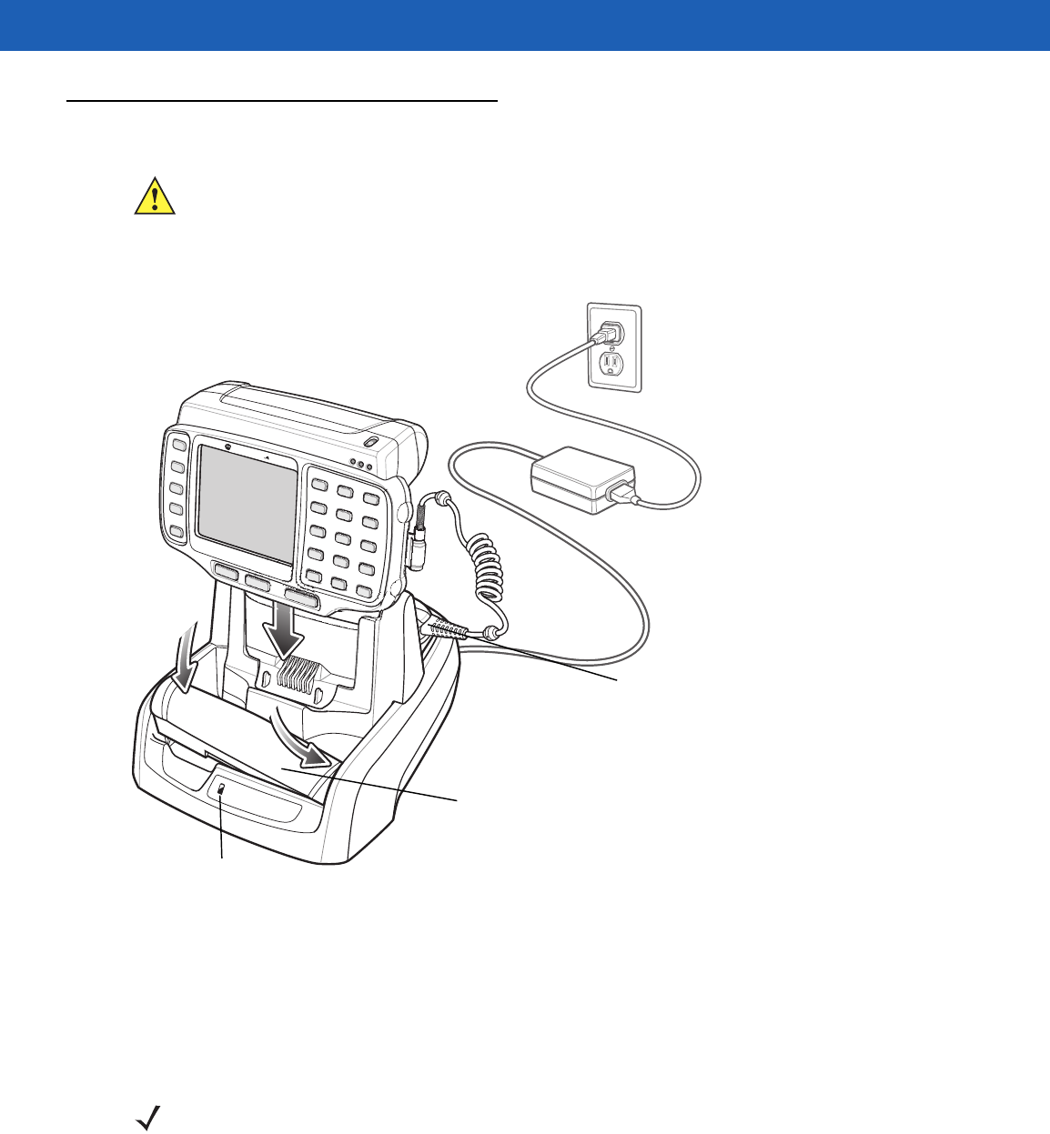
Single Slot USB Cradle
This section describes how to use a Single Slot USB cradle (Figure 5-1) with the wearable terminal. For USB
communication setup procedures refer to the WT41N0 Integrator Guide.
Figure 5-1
Single Slot USB Cradle
The Single Slot USB Cradle:
•
Provides 5.4 VDC power for operating the wearable terminal.
•
Provides USB port for data communication between the wearable terminal and a host computer or other
serial devices (e.g., a printer).
•
Synchronizes information between the wearable terminal and a host computer. (With customized or third
party software, it can also be used to synchronize the wearable terminal with corporate databases.)
•
Charges the wearable terminal’s battery and a spare battery.
•
Provides a location for storing a scanner when a wearable terminal is docked in the cradle.
CAUTION Ensure that you follow the guidelines for battery safety described in Battery Safety Guidelines on page
6-3.
NOTE The normal function of the product may be disturbed by Strong Electro Magnetic Interference (for
example, static electricity). If so, simply remove and re-insert the terminal to resume normal
operation. In case the function does not resume, please use the product in another location.
1
2
Spare Battery
Spare Battery
Charging LED
Scanner Placed in Well
DRAFT

5 - 4 WT41N0 User Guide
Battery Charging Indicators
The Single Slot USB cradle can charge the wearable terminal’s main battery and a spare battery
simultaneously.
The wearable terminal’s amber Charge Status LED indicates the status of the battery charging in the wearable
terminal. See Table 1-2 on page 1-7 for charging status indications.
The amber Spare Battery Charging LED on the cradle (see Figure 5-1 on page 5-3) indicates the status of the
spare battery charging in the cradle. See Table 5-2 for charging status indications. The standard capacity
battery fully charges in less than four hours and the extended capacity battery fully charges in less than eight
hours.
Table 5-2
Spare Battery LED Charging Indicators
Spare Battery LED
(on cradle) Indication
Off No spare battery in well; spare battery not placed correctly; cradle is not powered.
Fast Blinking Amber Charging error:
•
Temperature is too low or too high.
•
Charging has gone on too long without completing (typically eight hours).
Slow Blinking Amber Spare battery is charging.
Solid Amber Charging complete.
DRAFT
Getting Started 5 - 5
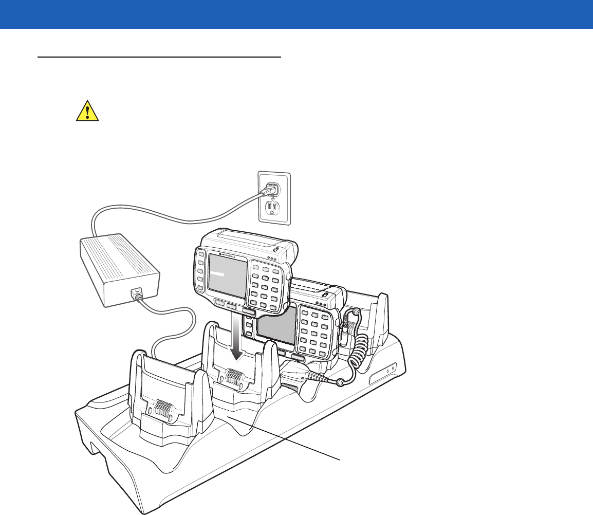
Four Slot Ethernet Cradle
This section describes how to use a Four Slot Ethernet cradle (Figure 5-2) with the wearable terminal. For
Ethernet communication setup procedures refer to the WT41N0 Integrator Guide.
Figure 5-2
Four Slot Ethernet Cradle
The Four Slot Ethernet cradle:
•
Connects up to four wearable terminals to an Ethernet network.
•
Provide 5.4 VDC power for operating the wearable terminal and charging the battery.
•
Simultaneously charges up to four wearable terminals (with batteries installed).
You cannot ActiveSync using the Four Slot Ethernet cradle. To ActiveSync with a host computer use the Single
Slot USB cradle.
Battery Charging
The four slot Ethernet cradle can charge up to four wearable terminals simultaneously. To charge the wearable
terminal:
CAUTION Ensure that you follow the guidelines for battery safety described in Battery Safety Guidelines on page
6-3.
Scanner Well
DRAFT

5 - 6 WT41N0 User Guide
1. Slide the wearable terminal into the wearable terminal slot.
2. The wearable terminal amber Charge Status LED indicates the wearable terminal battery charging status.
The standard capacity battery usually charges in less than four hours and the extended capacity battery
fully charges in less than eight hours. See Table 5-2 for charging status indications.
3. When charging is complete, remove the wearable terminal from the cradle.
LED Charge Indications
The Four Slot Ethernet cradle uses the wearable terminal amber Power LED to indicate the battery charging
status. See Table 5-2 on page 5-4 for charging status indications.
Speed LED
The green Speed LED lights to indicate that the transfer rate is 100 Mbps. When it is not lit it indicates that the
transfer rate is 10 Mbps.
Link LED
The yellow Link LED blinks to indicate activity, or stays lit to indicate that a link is established. When it is not lit,
it indicates that there is no link.
Battery Charging Indicators
The wearable terminal’s amber charge LED indicates the status of the battery charging in the wearable
terminal. See Table 1-2 on page 1-7 for charging status indications.
The standard capacity battery fully charges in less than four hours and the extended capacity battery fully
charges in less than eight hours.
DRAFT
Getting Started 5 - 7
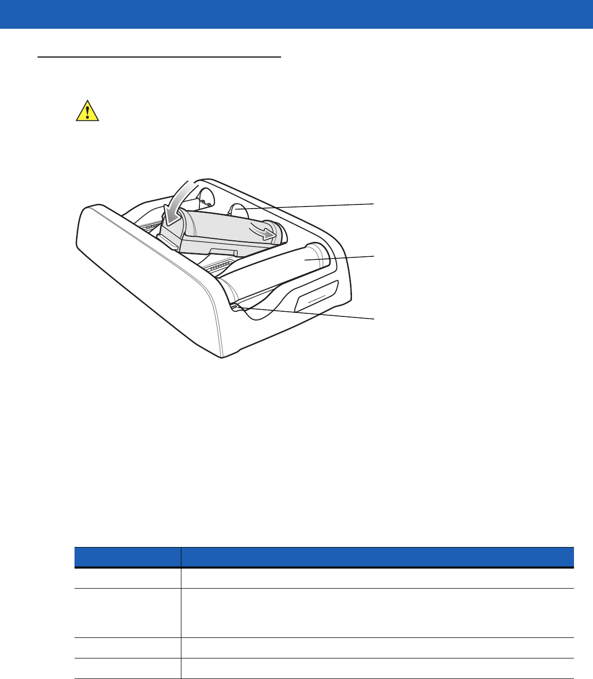
Four Slot Spare Battery Charger
This section describes how to use the Four Slot Spare Battery Charger to charge up to four wearable terminal
spare batteries.
Figure 5-3
Four Slot Spare Battery Charger
Spare Battery Charging with the Four Slot Spare Battery Charger
Insert the battery into a spare battery charging slot and gently press down on the battery to ensure proper
contact.
Battery Charging Indicators
An amber LED is provided on each battery charging well. See Table 5-3 for charging status indications.The
standard capacity battery usually charges in less than four hours and the extended capacity battery fully
charges in less than eight hours.
CAUTION Ensure that you follow the guidelines for battery safety described in Battery Safety Guidelines on page
6-3.
Spare Battery Charging LEDs (4)
Spare Battery
Spare Battery Charging Well (4)
Table 5-3
Spare Battery LED Charging Indicators
LED Indication
Off No spare battery in slot; spare battery not placed correctly; cradle is not powered.
Fast Blinking Amber Charging error:
•
Temperature is too low or too high.
•
Charging has gone on too long without completing (typically eight hours).
Slow Blinking Amber Spare battery is charging.
Solid Amber Charging complete.
DRAFT
5 - 8 WT41N0 User Guide
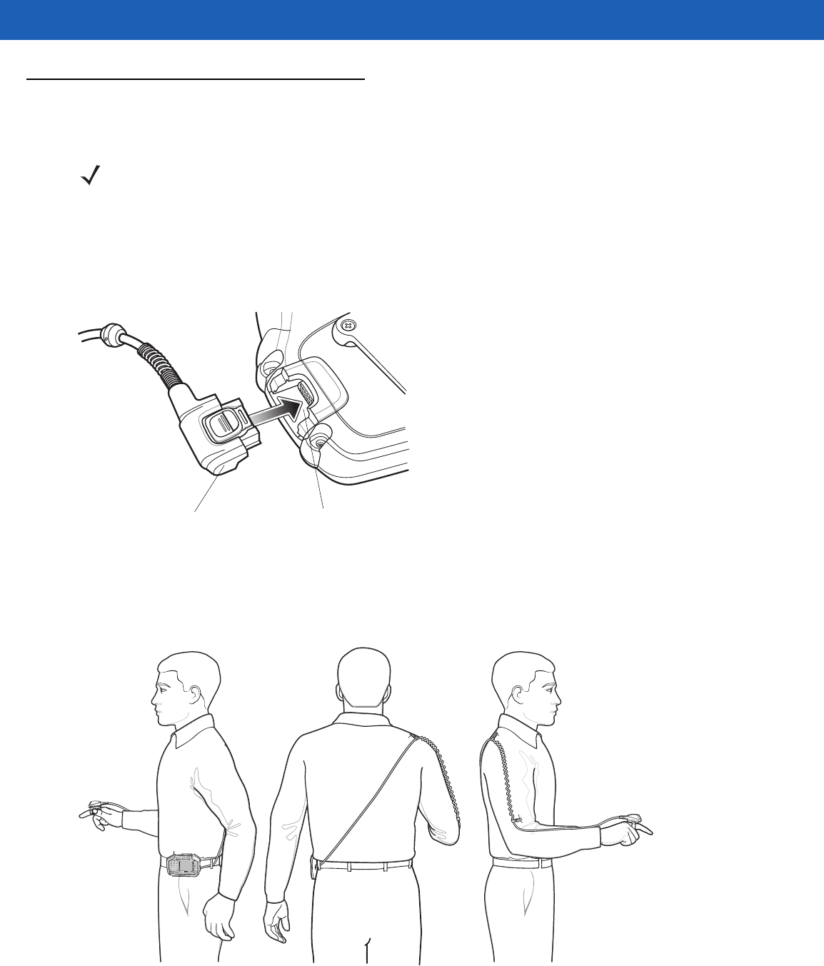
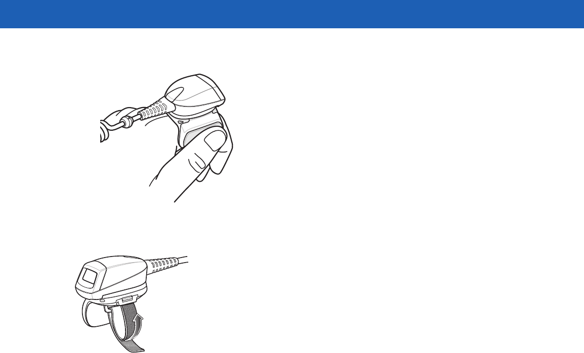
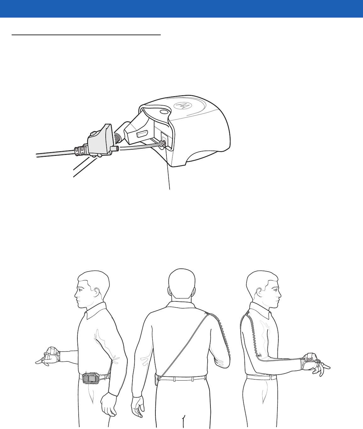
RS409/RS419 Scanner
To connect the RS409 or RS419 scanner to the wearable terminal:
1. Remove the rubber plug from the wearable terminal interface connector.
2. Connect the scanner interface cable to the wearable terminal interface connector. If the wearable terminal
is mounted on the arm, connect the cable to the interface connector closest to the wrist.
Figure 5-4
Connecting Scanner to Wearable Terminal
3. If using the extended cable configuration, route the scanner cable up to the shoulder and down to the hand
that the scanner mounts on. Attach two cable clips to clothing and secure cable to cable clip.
Figure 5-5
Cable Clip Installation
4. Rotate the trigger assembly to the correct position for the hand that the scanner mounts to.
NOTE There are two scanner configurations available. The short cable configuration connects the scanner to the
wearable terminal mounted on the arm. The extended cable configuration connects the scanner to the
WT41N0 mounted on the hip.
Scanner Cable Connector Interface Connector
DRAFT
Getting Started 5 - 9
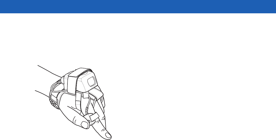
5. Slide the scanner onto the index finger with the scan trigger next to the thumb.
Figure 5-6
Place the Scanner on Index Finger
6. Tighten the finger strap.
Figure 5-7
Tightening Straps
7. If required, cut excess finger strap material.
After connecting the scanner, warm boot the wearable terminal. See Resetting the Wearable Terminal on page
2-17 for information on performing a warm boot.
DRAFT
5 - 10 WT41N0 User Guide
RS309 Scanner
The RS309 connects to the wearable terminal and mounts on the back of either hand using the RS309 glove.
1. Remove the rubber plug from the wearable terminal interface connector.
2. Connect the RS309 trigger cable to the back of the RS309.
Figure 5-8
Connecting Trigger Cable to RS309
3. Connect the end of the RS309 interface cable to the wearable terminal interface connector. If the wearable
terminal is mounted on the arm, connect the cable to the interface connector closest to the wrist.
4. If the wearable terminal is mounted on the hip, route the interface cable up to the shoulder and down to the
hand that the scanner mounts on. Attach two cable clips to clothing and secure cable to cable clip.
Figure 5-9
Cable Clip Installation
Trigger Connector
DRAFT
Getting Started 5 - 11
5. Mount the RS309 on the RS309 glove. Refer to the RS309 Glove Installation Guide for information on
mounting the RS309.
6. Route the trigger cable around the side of the RS309, next to the index finger.
7. Slide the trigger mount on the index finger, with the button positioned next to the thumb, and adjust the
velcro strap.
Figure 5-10
RS309 on Back of Hand
After connecting the scanner, warm boot the wearable terminal. See Resetting the Wearable Terminal on page
2-17 for information on performing a warm boot.
DRAFT

5 - 12 WT41N0 User Guide
RS507 Imager
Refer to the RS507 Hands-free Imager Quick Reference Guide, p/n 72-115987-xx and the RS507 Hands-free
Imager Product Reference Guide, p/n 72E-120802-xx for detailed information.
Freezer Pouch
The freezer pouch allows the user to use the wearable terminal in a freezer environment on the hip or wrist for
use in voice picking applications. An RS309, RS409 or RS419 scanner with an extended cable is required
when mounting the freezer pouch on the hip mount, if scanning is also part of the application.
In order to keep the wearable terminal at a safe operating temperature in a meat or ice cream freezer, the
freezer pouch insulates the wearable terminal to keep the heat generated by the wearable terminal within the
pouch. The pouch is not heated. There are no batteries to worry about or electronics within the pouch.
The freezer pouch can be either hip-mounted or wrist-mounted. For hip-mounting, there is a belt loop on its
back for attached a belt (sold separately). For wrist-mounting, customers can buy either a set of
standard-length or longer-length wrist straps and use them with the pouch. The longer-length wrist straps are
recommended for wrist-mounting over coats. The freezer pouch has openings on each side for wearable
scanners and headset adapters.
While the freezer pouch is designed to allow workers to use the wearable terminal in meat and ice cream
freezers, there are some very important limitations to follow:
•
Do not use in environments that are below -30°C (-22°F).
•
Do not allow the wearable terminal (with or without the freezer pouch) to remain in the suspend mode in
environments below -20°C (-4°F) for more than 10 minutes. This prevents the wearable terminal from
cooling down to the ambient freezer temperature. The pouch maintains the wearable terminal at a
sufficient temperature while it is in use, but lengthy periods of inactivity bring the wearable terminal below
its operating temperature.
•
Do not store wearable terminals in the meat or ice cream freezer. As explained above, this would allow
the wearable terminals to chill to the ambient freezer temperature, which is below their operating
temperature. Furthermore, if batteries were left in wearable terminals stored in the freezer, the batteries
themselves could freeze, which could damage them. At the least, they would not function while frozen.
•
Batteries cannot be charged below 0°C (32°F). Motorola cradles and battery chargers have an automatic
shut-off to insure this.
•
If using wearable scanners with the wearable terminal in the meat or ice cream freezer for a shift,
remember that the RS309 freezer configuration is the correct scanner to choose, due to its lower
operating temperature range and its desiccant pack to remove condensation.
Slide the wearable terminal into the freezer pouch.
NOTE Wearable computers with standard capacity batteries must use the Standard Capacity Battery Freezer
Pouch while wearable computers with extended capacity batteries must use the Extended Capacity
Battery Freezer Pouch. See Table 5-1 on page 5-1 for more information.
CAUTION Do not use the wearable terminal with touch screen in the freezer pouch or in environments that are
below -20°C (-4°F).
DRAFT
Getting Started 5 - 13
Figure 5-11
Insert Wearable Terminal into Freezer Pouch
Close the front flap followed by the back flap.
Figure 5-12
Close Freezer Pouch Flaps
Slide a belt through the belt loop on the back of the freezer pouch. The wearable terminal can be mounted
right-side up or up-side down depending upon user preference or application.
DRAFT
5 - 14 WT41N0 User Guide
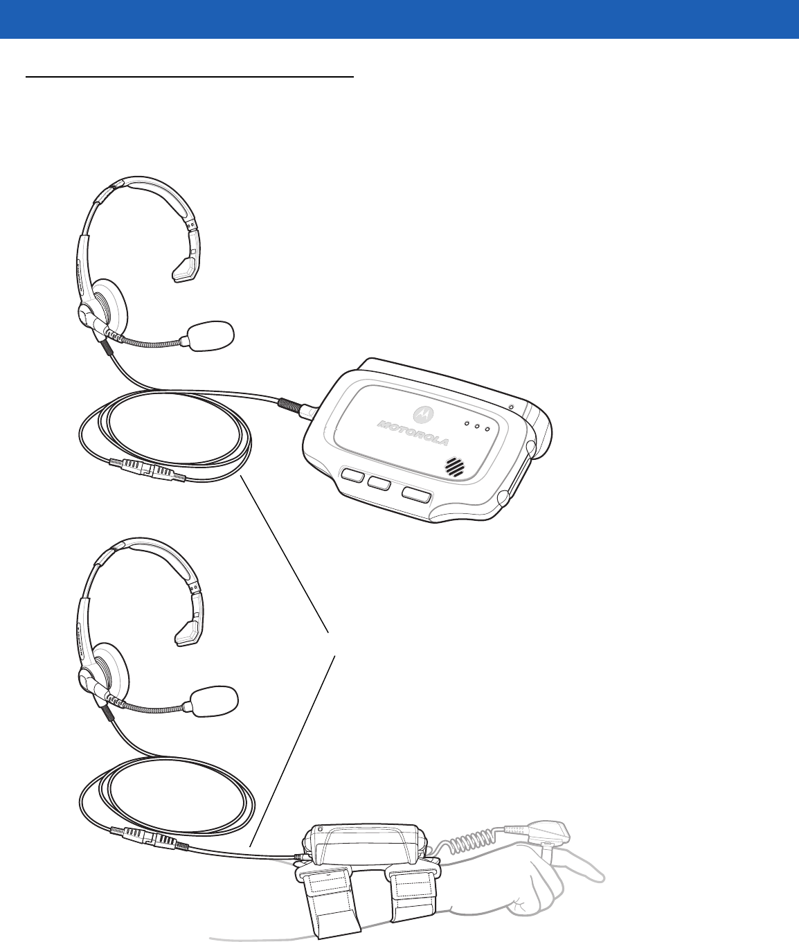
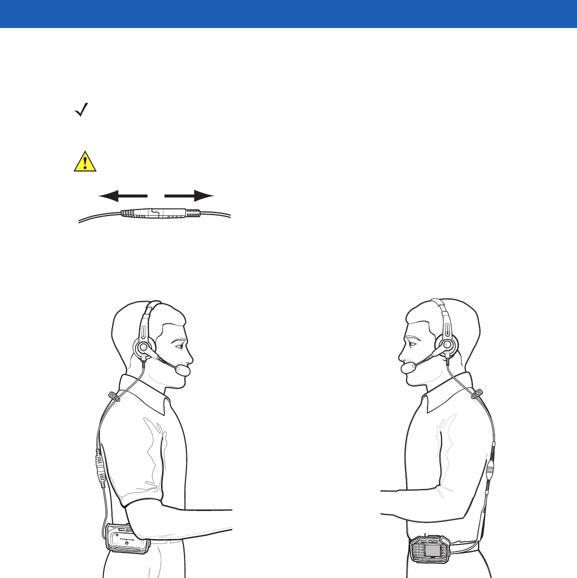
Wired Headset
You can use a mono headset with a microphone for audio communication with an audio enabled application.
The Headset Cable Adapter is required to connect a headset with the wearable terminal.
Figure 5-13
Typical Headset Connected to Headset Adapter
Headset Cable Adapter
DRAFT
Getting Started 5 - 15
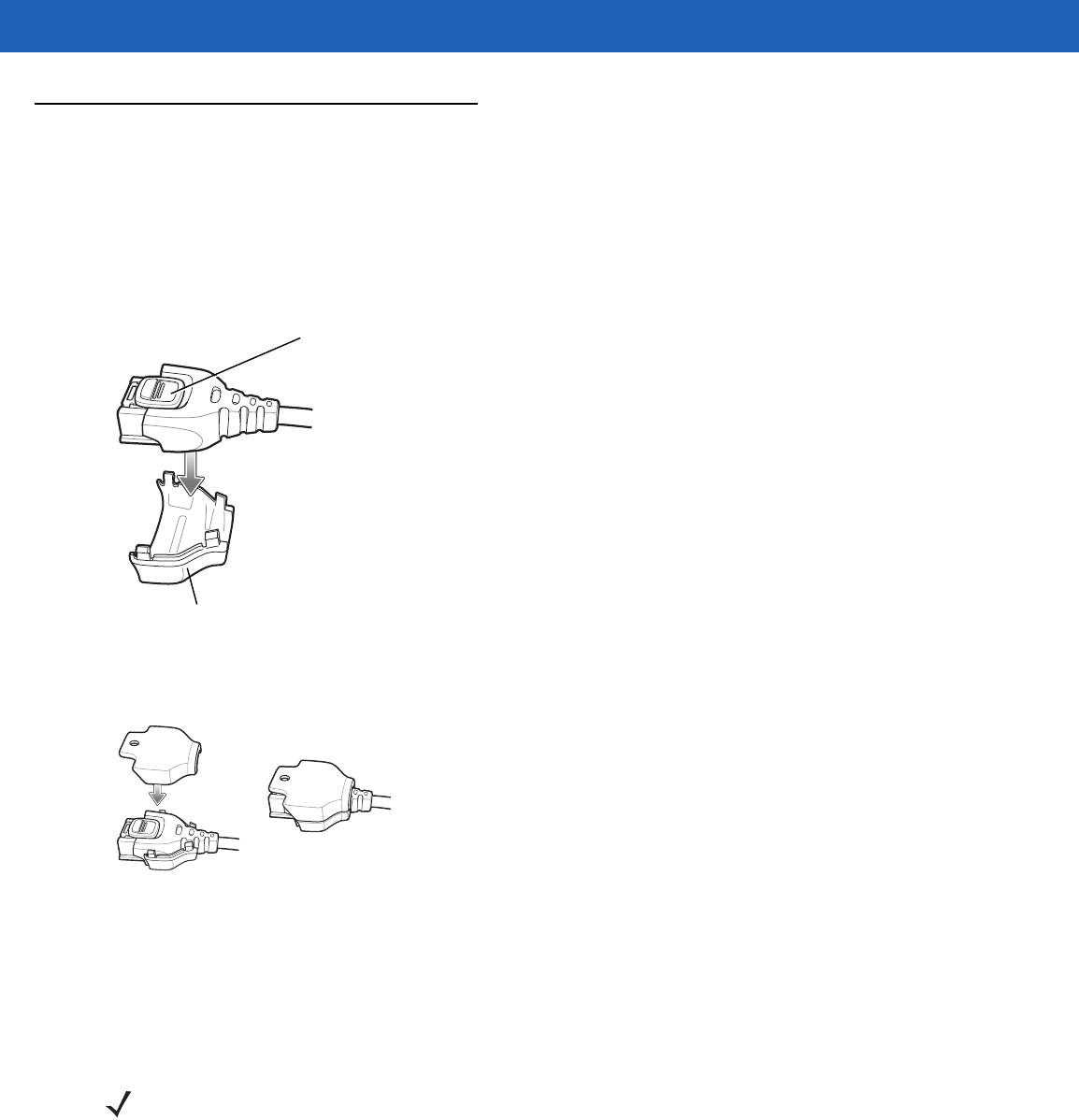
The headset cable adapter connects the headset to the wearable terminal. Connect the headset connect end
of the adapter to the headset connector. Plug the other end of the adapter to the wearable terminal interface
connector.
Figure 5-14
Disconnecting Headset from Headset Adapter
Figure 5-15
Headset Connected to wearable Terminal on Hip
NOTE Not all headset plugs are compatible with the headset cable adapter.
CAUTION When disconnecting the headset from the headset adapter, pull the two connectors away
from each. Do not bend connectors to disconnect.
DRAFT
5 - 16 WT41N0 User Guide
Connector Shroud
Assembly
1. Remove cable from wearable terminal, if required.
2. Align the cable connector with the connector shroud bottom housing. Ensure that the disconnect button on
the connector faces up.
Figure 5-16
Installing Bottom Housing
3. Place the cable connector into the shroud bottom housing as shown.
Figure 5-17
Installing Top Housing
4. Press the top housing into the bottom housing. The housings will snap together.
5. Plug the cable connector into the wearable terminal connector.
Disconnecting the Cable from the Wearable Terminal
1. Turn the wearable terminal over to expose the top housing of the shroud.
2. Push the tip of a ball-point pen through the hole in the connector shroud top housing. The connector
disengages from the wearable terminal.
Disconnect Button
Bottom Housing
NOTE Follow the instructions below when disconnecting the cable connector and shroud from the wearable terminal.
Once the shroud is installed on the connector, do not disassemble the shroud by prying it apart.
DRAFT

Getting Started 5 - 17
Figure 5-18
Disconnecting Connector with Shroud
Connector Eject Hole
DRAFT

5 - 18 WT41N0 User Guide
DRAFT

CHAPTER 6 MAINTENANCE &
TROUBLESHOOTING
Introduction
This chapter includes instructions on cleaning and storing the wearable terminal, and provides troubleshooting
solutions for potential problems during wearable terminal operation.
Maintaining the Wearable Terminal
For trouble-free service, observe the following tips when using the wearable terminal:
•
Do not scratch the touch screen of the wearable computer. When activating with the wearable computer
touch screen, use finger tips. Never use a pen or pencil or other sharp object on the surface of the
screen.
Motorola requires using a screen protector, p/n KT-114032-01R or KT-114032-02R.
•
A screen protector is applied to the wearable computer touch screen. Motorola requires using this to
minimize wear and tear. Screen protectors enhance the usability and durability of touch screen displays.
Benefits include:
•Protection from scratches and gouges
•Durable touch surface with tactile feel
•Abrasion and chemical resistance
•Keeping the device’s screen looking new
•Quick and easy installation.
•
Protect the wearable terminal with a touch screen from temperature extremes.
•
Do not store or use the wearable terminal with a touch screen in any location that is extremely dusty,
damp, or wet.
•
Use a soft lens cloth to clean the wearable terminal display/touch panel.
•
Periodically replace the rechargeable Li-ion battery to ensure maximum battery life and product
performance. Battery life depends on individual usage patterns.
•
The screen of the wearable terminal contains glass. Take care not to drop the wearable terminal or
subject it to strong impact.
DRAFT
6 - 2 WT41N0 User Guide
•
Regularly replace all Velcro® straps on the wrist mount and wearable scanners, to ensure adequate
adhesion of the Velcro.
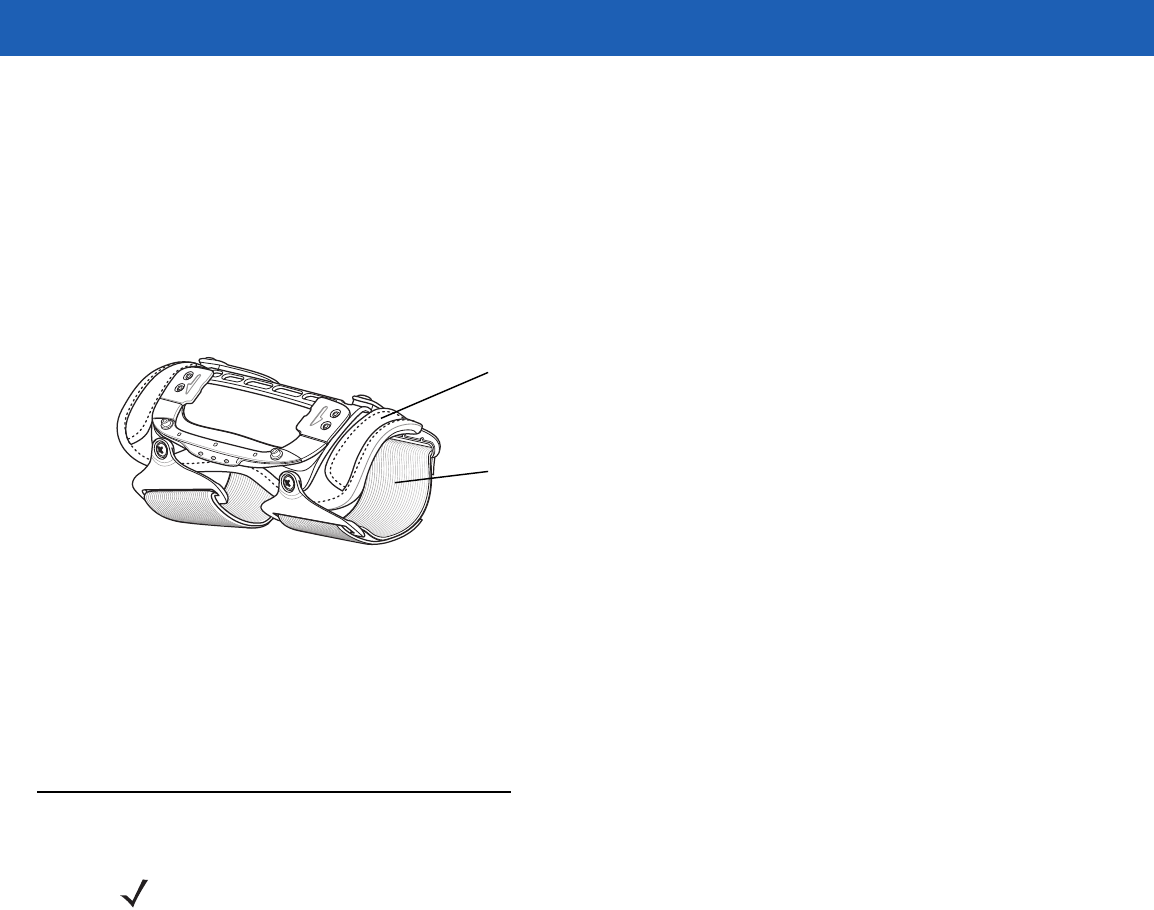
Wrist Mount Cleaning Instructions
It may be necessary to wash the wrist mount straps and replaceable pad when they become soiled.
Remove the straps and pad from the wrist mount. Hand wash in cold water with a mild detergent (such as
Woolite®). Do not use bleach. Air dry. Do not use a dryer.
Figure 6-1
Wrist Mount Soft Goods
Arm Sleeve Cleaning Instructions
It may be necessary to wash the arm sleeve when it become soiled.
Hand wash in cold water with a mild detergent (such as Woolite®). Do not use bleach. Air dry. Do not use a
dryer.
Removing the Screen Protector
A screen protector is applied to the wearable terminal with touch screen. Motorola recommends using this to
minimize wear and tear. Screen protectors enhance the usability and durability of touch screen displays.
To remove the screen protector, lift the corner using a thin plastic card, such as a credit card, then carefully lift
it off the display.
Replaceable Pad
Strap
NOTE Not using a screen protector on a wearable terminal with a touch screen can affect warranty coverage.
To purchase replacement protectors, contact your local account manager or Motorola, Inc. These include
screen protector installation instructions. Part number: KT-114032-01Ror KT-114032-02R Screen
Protector 3/pk.
DRAFT
Getting Started 6 - 3
Figure 6-2
Removing the Screen Protector
Battery Safety Guidelines
•
The area in which the units are charged should be clear of debris and combustible materials or
chemicals. Particular care should be taken where the device is charged in a non commercial
environment.
•
Improper battery use may result in a fire, explosion, or other hazard.
•
To charge the mobile device battery, the battery and charger temperatures must be between 0 ºC and
+40 ºC (+32 ºF and +104 ºF).
•
Do not use incompatible batteries and chargers. Use of an incompatible battery or charger may present
a risk of fire, explosion, leakage, or other hazard. If you have any questions about the compatibility of a
battery or a charger, contact Motorola Enterprise Mobility support.
•
Do not disassemble or open, crush, bend or deform, puncture, or shred.
•
Severe impact from dropping any battery-operated device on a hard surface could cause the battery to
overheat.
•
Do not short circuit a battery or allow metallic or conductive objects to contact the battery terminals.
•
Do not modify or remanufacture, attempt to insert foreign objects into the battery, immerse or expose to
water or other liquids, or expose to fire, explosion, or other hazard.
•
Do not leave or store the equipment in or near areas that might get very hot, such as in a parked vehicle
or near a radiator or other heat source. Do not place battery into a microwave oven or dryer.
•
Battery usage by children should be supervised.
•
Please follow local regulations to promptly dispose of used re-chargeable batteries.
•
Do not dispose of batteries in fire.
Lift Screen
Protector
Corner
CAUTION Do not use a sharp object to remove the protector. Doing so can damage the touch screen.
DRAFT

6 - 4 WT41N0 User Guide
•
Seek medical advice immediately if a battery has been swallowed.
•
In the event of a battery leak, do not allow the liquid to come in contact with the skin or eyes. If contact
has been made, wash the affected area with large amounts of water and seek medical advice.
•
If you suspect damage to your equipment or battery, contact Motorola Enterprise Mobility support to
arrange for inspection.
Cleaning
Materials Required
•
Alcohol wipes
•
Soft lens cloth
•
Cotton tipped applicators
•
Isopropyl alcohol
•
Can of compressed air with a tube.
Cleaning the Wearable Terminal
Housing
Using the alcohol wipes, wipe the housing including keys and in-between keys.
Display
The display can be wiped down with the alcohol wipes, but care should be taken not to allow any pooling of
liquid around the edges of the display. Immediately dried the display with a soft, non-abrasive cloth to prevent
streaking. For WT41N0 with touch panel, only use a soft lens cloth to clean the touch panel overlay surface.
Connectors
Clean all three connectors, two interface connectors on the sides of the wearable terminal and the cradle
connector on the back.
1. Remove the main battery from mobile computer. See Installing and Removing the Main Battery on page
1-6.
2. Remove connector rubber plugs, if required.
WARNING!Avoid exposing this product to contact with hot oil or other flammable liquids. If such
exposure occurs, unplug the device and clean the product immediately in accordance with
these guidelines.
CAUTION Always wear eye protection.
Read warning label on compressed air and alcohol product before using.
If you have to use any other solution for medical reasons please contact Motorola for more
information.
DRAFT

Getting Started 6 - 5
3. Dip the cotton portion of the cotton tipped applicator in isopropyl alcohol.
4. Rub the cotton portion of the cotton tipped applicator back-and-forth across each connector. Do not leave
any cotton residue on the connector.
5. Repeat at least three times.
6. Use the cotton tipped applicator dipped in alcohol to remove any grease and dirt near the connector area.
7. Use a dry cotton tipped applicator and repeat steps 4 through 7.
8. Spray compressed air on the connector areas by pointing the tube/nozzle about ½ inch away from the
surface.
9. Inspect the area for any grease or dirt, repeat if required.
10. Replace connector rubber plugs, if required.
Cleaning the RS309, RS409, RS419 and RS507
Housing
Using the alcohol wipes, wipe the housing including keys and in-between keys.
Scanner Exit Window
Wipe the scanner exit window periodically with a lens cloth or other material suitable for cleaning optical
material such as eyeglasses.
Connectors
1. Disconnect the scanner from mobile computer.
2. Dip the cotton portion of the cotton tipped applicator in isopropyl alcohol.
3. Rub the cotton portion of the cotton tipped applicator back-and-forth across the connector pins. Do not
leave any cotton residue on the connector.
4. Repeat at least three times.
5. Use the cotton tipped applicator dipped in alcohol to remove any grease and dirt near the connector area.
6. Use a dry cotton tipped applicator and repeat steps 3 through 5.
7. Spray compressed air on the connector area by pointing the tube/nozzle about ½ inch away from the
surface.
8. Inspect the area for any grease or dirt, repeat if required.
CAUTION Do not point nozzle at yourself and others, ensure the nozzle or tube is away from your face.
CAUTION Do not point nozzle at yourself and others, ensure the nozzle or tube is away from your face.
DRAFT

6 - 6 WT41N0 User Guide
Cleaning Cradle Connectors
To clean the connectors on a cradle:
1. Remove the DC power cable from the cradle.
2. Dip the cotton portion of the cotton tipped applicator in isopropyl alcohol.
3. Rub the cotton portion of the cotton tipped applicator along the pins of the connector. Slowly move the
applicator back-and-forth from one side of the connector to the other. Do not let any cotton residue on the
connector.
4. All sides of the connector should also be rubbed with the cotton tipped applicator.
5. Spray compressed air in the connector area by pointing the tube/nozzle about ½ inch away from the
surface.
6. Ensure that there is no lint left by the cotton tipped applicator, remove lint if found.
7. If grease and other dirt can be found on other areas of the cradle, use lint free cloth and alcohol to remove.
Cleaning Frequency
The cleaning frequency is up to the customer’s discretion due to the varied environments in which the mobile
devices are used. They may be cleaned as frequently as required. However when used in dirty environments it
may be advisable to periodically clean the ring scanners’ exit windows to ensure optimum scanning
performance.
CAUTION Do not point nozzle at yourself and others, ensure the nozzle or tube is away from your face.
CAUTION Allow at least 10 to 30 minutes (depending on ambient temperature and humidity) for the alcohol to air
dry before applying power to cradle.
If the temperature is low and humidity is high, longer drying time is required. Warm temperature and
dry humidity requires less drying time.
DRAFT
Getting Started 6 - 7
Troubleshooting
Wearable Terminal
Table 6-1
Troubleshooting the Wearable Terminal
Problem Cause Solution
Wearable terminal
does not turn on. Lithium-ion battery
not charged. Charge or replace the lithium-ion battery in the
wearable
terminal
.
Lithium-ion battery
not installed
properly.
Ensure battery is installed properly. See
Installing and
Removing the Main Battery on page 1-6
.
System crash. Perform a warm boot. If the
wearable terminal
still does not turn
on, perform a cold boot. See
Resetting the Wearable Terminal
on page 2-17
.
Rechargeable
lithium-ion battery did
not charge.
Battery failed. Replace battery. If the
wearable terminal
still does not operate,
try a warm boot, then a cold boot. See
Resetting the Wearable
Terminal on page 2-17
.
Wearable terminal
removed from
cradle while battery
was charging.
Insert
wearable terminal
in cradle and begin charging. The
standard capacity battery fully charges in less than four hours
and the extended capacity battery fully charges in less than
eight hours
.
Ambient
temperature of the
cradle is too warm
or too cold.
Move the cradle to an area where the ambient temperature is
between 0 °C and 40 °C (32 °F and 104 °F).
Cannot see
characters on
display.(not applicable
to voice only
configuration)
Wearable terminal
not powered on. Press the Power button.
Screen protective is
scratched or hazy. Replace screen protector.
Display is hard to
read. (not applicable
to voice only
configuration)
Screen protective is
scratched or hazy. Replace screen protector.
DRAFT

6 - 8 WT41N0 User Guide
During data
communication, no
data was transmitted,
or transmitted data
was incomplete.
Wearable terminal
removed from
cradle or unplugged
from host computer
during
communication.
Replace the
wearable terminal
in the cradle, or reattach the
Synchronization cable and re-transmit.
Incorrect cable
configuration. See the System Administrator.
Communication
software was
incorrectly installed
or configured.
Perform setup. Refer to the WT41N0 Integrator Guide for
details.
Ensure that Microsoft ActiveSync 4.5 or greater is installed on
the host computer.
No sound is audible. Volume setting is
low or turned off. Adjust volume. Change volume settings by selecting
Start
>
Settings
>
Control Panel
>
Volume & Sounds
icon >
Volume
tab.
Move the slider to change the volume level or use volume
control on voice application.
Wearable terminal
turns itself off. Wearable terminal
is inactive. The
wearable terminal
turns off after a period of inactivity. If the
wearable terminal
is running on battery power, this period can
be set to 30 sec., 1, 2, 3, 4, 5 or 6 minutes. If the
wearable
terminal
is running on external power, this period can be set to
1, 2, 3, 5, 10, 15 and 30 minutes.
Check the power settings by selecting
Start
>
Settings
>
Control
Panel
>
Power
icon >
Power Off
tab.
Change the setting if you need a longer delay before the
automatic shutoff feature activates.
Voice Only
WT41N0 was set to
suspend.
Return Voice Only WT41N0 suspend setting to factory default
(disabled).
Battery is depleted. Replace or recharge the battery.
Battery is not
inserted properly. Insert the battery properly (see
Installing and Removing the
Main Battery on page 1-6
).
The
wearable
terminal
’s battery is
low and it powers
down to protect
memory content.
Replace or recharge the battery.
A message appears
stating that the
wearable terminal
memory is full.(not
applicable to voice
only configuration)
Too many files
stored on the
wearable terminal
.
Delete unused memos and records. You can save these records
on the host computer.
Too many
applications
installed on the
wearable terminal
.
If you have installed additional applications on the
wearable
terminal
, remove them to recover memory.
Select
Start
>
Settings
>
Control Panel
>
Remove Programs
icon.
Select the unused program and select Remove.
Table 6-1
Troubleshooting the Wearable Terminal (Continued)
Problem Cause Solution
DRAFT

Getting Started 6 - 9
The
wearable
terminal
does not
accept scan input.
Scanning
application is not
loaded.
Verify that the unit is loaded with a scanning application. See the
System Administrator.
Unreadable bar
code. Ensure the symbol is not defaced.
Distance between
exit window and bar
code is incorrect.
Ensure
wearable terminal
is within proper scanning range.
Wearable terminal
is not programmed
for the bar code.
Ensure the
wearable terminal
is programmed to accept the type
of bar code being scanned.
Wearable terminal
is not programmed
to generate a beep.
If a beep on a good decode is expected and a beep is not heard,
check that the application is set to generate a beep on good
decode.
Battery is low. If the scanner stops emitting a laser beam when the trigger is
pressed, check the battery level. When the battery is low, the
scanner shuts off before the
wearable terminal
low battery
condition notification.
Note: If the scanner is still not reading symbols, contact the
distributor or Motorola.
Wearable terminal
goes into IPL mode
after cold boot.
Headset adapter
without a headset is
connected to the
wearable terminal
during a cold boot.
Disconnect the headset adapter prior to performing a cold boot.
Update to a newer operating system (OEM version 05.30.0000
or higher).
Scanner trigger is
held down during a
cold boot.
Do not press trigger during a cold boot.
P1 or P2 key is held
down during a cold
boot.
Do not press the P1 or P2 key during a cold boot.
If all three LEDs are lit
solid. Voice Only
WT41N0 is in IPL
mode.
Perform cold boot. See
Resetting the Wearable Terminal on
page 2-17
.
WLAN connection is
lost when the
wearable terminal
is
connected to a host
computer using
ActiveSync.
Microsoft security
feature prevents
connection to two
separate networks.
Disconnect from the WLAN network prior to connecting to a host
computer using ActiveSync.
Table 6-1
Troubleshooting the Wearable Terminal (Continued)
Problem Cause Solution
DRAFT

6 - 10 WT41N0 User Guide
Wearable terminal
cannot find any
Bluetooth devices
nearby.
Too far from other
Bluetooth devices. Move closer to the other Bluetooth device(s), within a range of
10 meters.
The Bluetooth
device(s) nearby
are not turned on.
Turn on the Bluetooth device(s) you wish to find.
The Bluetooth
device(s) are not in
discoverable mode.
Set the Bluetooth device(s) to discoverable mode. If needed,
refer to the device’s user documentation for help.
Table 6-1
Troubleshooting the Wearable Terminal (Continued)
Problem Cause Solution
DRAFT

Getting Started 6 - 11
Four Slot Ethernet Cradle
Table 6-2
Troubleshooting the Four Slot Ethernet Cradle
Problem Cause Solution
Wearable terminal amber
Charge Status LED does not
light when
wearable terminal
inserted.
Cradle is not receiving power. Ensure the power cable is connected
securely to both the cradle and to AC power.
Wearable terminal is not
correctly seated. Remove and re-insert the
wearable terminal
into the cradle, ensuring it is correctly seated.
Wearable terminal battery is
not charging. Wearable terminal was
removed from cradle or cradle
was unplugged from AC power
too soon.
Ensure cradle is receiving power. Ensure the
wearable terminal
is seated correctly. If the
wearable terminal
battery is fully depleted, it
can take up to four hours to fully recharge a
standard capacity battery and it can take up
to eight hours to fully recharge an extended
capacity battery.
Battery is faulty. Verify that other batteries charge properly. If
so, replace the faulty battery.
The
wearable terminal
is not
fully seated in the cradle. Remove and re-insert the
wearable terminal
into the cradle, ensuring it is correctly seated.
Ambient temperature of the
cradle is too warm or too cold. Move the cradle to an area where the
ambient temperature is between 0 °C and 40
°C (32 °F and 104 °F).
During data communication,
no data was transmitted, or
transmitted data was
incomplete.
Wearable terminal removed
from cradle during
communication.
Replace
wearable terminal
in cradle and
retransmit.
Incorrect cable configuration. See the system administrator or refer to the
WT41N0 Integrator Guide.
Ethernet connection error. Link
LED is not lit (see
Link LED on
page 5-6
).
See the system administrator. Probable
Ethernet connection error.
Wearable terminal’s main
batteries not charging. Ambient temperature of the
cradle is too warm or too cold. Move the cradle to an area where the
ambient temperature is between 0 °C and 40
°C (32 °F and 104 °F).
DRAFT

6 - 12 WT41N0 User Guide
Four Slot Spare Battery Charger
Table 6-3
Troubleshooting The Four Slot Spare Battery Charger
Symptom Possible Cause Solution
Batteries not
charging. Battery was removed
from the charger or
charger was unplugged
from AC power too
soon.
Re-insert the battery in the charger or re-connect the charger’s
power supply.
Battery is faulty. Verify that other batteries charge properly. If so, replace the faulty
battery.
Battery contacts not
connected to charger. Verify that the battery is oriented properly and firmly seated in the
battery well correctly with the contacts facing down. See Figure 5-3
on page 5-7 for proper battery orientation.
Ambient temperature of
the charger is too warm
or too cold.
Move the charger to an area where the ambient temperature is
between 0 °C and 40 °C (32 °F and 104 °F).
DRAFT

Getting Started 6 - 13
Single Slot USB Cradle
Table 6-4
Troubleshooting the Single Slot USB Cradle
Symptom Possible Cause Solution
Charge Status
LEDs do not light
when
wearable
terminal
or spare
battery is
inserted.
Cradle is not receiving
power. Ensure the power cable is connected securely to both the cradle
and to AC power.
Wearable terminal is
not seated firmly in the
cradle.
Remove and re-insert the
wearable terminal
into the cradle,
ensuring it is firmly seated.
Spare battery is not
seated firmly in the
cradle.
Remove and re-insert the spare battery into the charging slot,
ensuring it is firmly seated.
Wearable
terminal battery
is not charging.
Wearable terminal was
removed from cradle or
cradle was unplugged
from AC power too
soon.
Ensure cradle is receiving power. Ensure
wearable terminal
is
seated correctly. Confirm main battery is charging. If a
wearable
terminal
battery is fully depleted, it can take up to four hours to
fully recharge a standard capacity battery and up to eight hours for
an extended capacity battery (if the
wearable terminal
is off, and
longer if the
wearable terminal
is operating).
View battery status by selecting
Start
>
Settings
>
Control Panel
>
Power
icon.
Battery is faulty. Verify that other batteries charge properly. If so, replace the faulty
battery.
The
wearable terminal
is not fully seated in
the cradle.
Remove and re-insert the
wearable terminal
into the cradle,
ensuring it is firmly seated.
Ambient temperature
of the cradle is too
warm or too cold.
Move the cradle to an area where the ambient temperature is
between 0°C and 40°C (32°F and 104°F).
Spare battery is
not charging. Battery inserted
incorrectly. Verify that the battery is oriented properly and firmly seated in the
battery well correctly with the contacts facing down. See Figure
5-3 on page 5-7 for proper battery orientation.
Battery is faulty. Verify that other batteries charge properly. If so, replace the faulty
battery.
Ambient temperature
of the cradle is too
warm or too cold.
Move the cradle to an area where the ambient temperature is
between 0 °C and 40 °C (32 °F and 104 °F).
DRAFT

6 - 14 WT41N0 User Guide
During data
communications,
no data was
transmitted, or
transmitted data
was incomplete.
Wearable terminal
removed from cradle
during
communications.
Replace
wearable terminal
in cradle and retransmit.
Incorrect cable
configuration. See the System Administrator.
Communications
software is not
installed or configured
properly.
Perform setup as described in the WT41N0 Integrator Guide.
Ensure that Microsoft ActiveSync 4.1 or greater is installed on the
host computer.
Cannot
ActiveSync with
Host Computer
Wrong USB cable
used. Ensure that the cable has a USB A connector on one end and a
USB mini B connector on the other end.
Host computer not
configured properly. Ensure that ActiveSync on the host computer is set to allow USB
connections.
The
wearable terminal
is not fully seated in
the cradle.
Remove and re-insert the
wearable terminal
into the cradle,
ensuring it is firmly seated.
Table 6-4
Troubleshooting the Single Slot USB Cradle (Continued)
Symptom Possible Cause Solution
DRAFT

APPENDIX ASPECIFICATIONS
Technical Specifications
The following tables summarize the wearable terminal’s intended operating environment and general technical
hardware specifications.
Wearable Terminal
The following table summarizes the wearable terminal’s intended operating environment.
Table A-1
Technical Specifications
Item Description
Physical and Environmental Characteristics
Dimensions With standard battery: 5.7 inches L x 3.7 inches W x 1.0 inch H (14.2 cm L x
9.3 cm W x 2.6 cm H)
With extended battery: 5.7 inches L x 4.2 inches W x 1.0 inch H (14.2 cm W x
10.7 cm H x 2.6 cm D)
Weight With standard battery: 11.3 oz. (320 g)
With extended battery: 12.2 oz. (345 g).
Keyboard
WT41N0: Two-color Alphanumeric Keypad
Voice Only WT41N0: Three programmable function keys
Display WT41N0: Color 2.8 inch QVGA non-touch or touch screens
Voice Only WT41N0: None
Main Battery Removable, rechargeable 3.7 VDC Lithium Ion battery.
Standard capacity: 2330 mAh (minimum)
Extended capacity: 4600 mAh (minimum)
Backup Battery Two NiMH batteries (rechargeable) 15 mAh 2.4 VDC (not user accessible)
Performance Characteristics
CPU OMAP 4 processor at 1 GHz
Operating System Microsoft Windows CE 7.0 Professional
DRAFT

A - 2 WT41N0 User Guide
Memory 2 GB Flash/512 MB RAM
Application Development PSDK, DCP and EMDK
Data Capture Options RS309 scanner
RS409 scanner
RS419 scanner
RS507 Hands-free imager
User Environment
Operating Temperature -4 °F to 122°F (-20 °C to 50 °C)
Storage Temperature -40 °F to 158 °F (-40 °C to 70 °C)
Battery Charging Temperature 32 °F to 104 °F (0 °C to +40 °C) ambient temperature range.
Humidity 5% to 95% non condensing
Drop Specification Multiple 4 ft.(1.2 m) drops to concrete across operating temperature range
Tumble 500 half-meter tumbles at room temperature (1,000 drops)
Environmental Sealing IP54 Category 2
ESD ± 15k VDC air discharge
± 8k VDC direct discharge
± 8k VDC indirect discharge
WLAN Wireless Data Communications
WLAN radio 802.11a/b/g/n
Operating Channels Channel 8 - 169 (5040 - 5845 MHz) (4920 - 4980 MHz) Japan only
Channel 1 - 13 (2412 - 2472 MHz)
Channel 14 (2484 MHz) Japan only
Actual operating frequencies depend on regulatory rules and certification
agency
Security WPA2, WEP (40 or 128 bit), TKIP, TLS, TTLS (MS-CHAP), TTLS (MS-CHAP
v2), TTLS (CHAP), TTLS-MD5, TTLS-PAP, PEAP-TLS, PEAP (MS-CHAP v2),
AES, LEAP, CCX v3
Voice Communication Runs voice recognition engines and text-to-speech engines for voice picking
applications
Output Power 100 mW U.S. and International
Data Rate 802.11a: up to 54Mb per second
802.11b: up to 11Mb per second
802.11g: up to 54Mb per second
Frequency Range 802.11a: 5 GHz; country-dependent
802.11b: 2.4 GHz; country-dependent
802.11g: 2.4 GHz; country-dependent
Antenna Internal
WPAN Wireless Data Communications
Bluetooth Bluetooth Version 1.2
Table A-1
Technical Specifications (Continued)
Item Description
DRAFT
Specifications A - 3
RS309 Scanner
Peripherals and Accessories
Cradles Single Slot USB
Four Slot Ethernet
Printers Supports extensive line of approved printers, cables and accessories
Charger Four Slot Battery Charger
Other Accessories Headset adapter, freezer pouch, hip mount and wrist mount.
Table A-1
Technical Specifications (Continued)
Item Description
Table A-2
RS309 Technical Specifications
Item Description
Physical and Environmental Characteristics
Dimensions (standard version
without cables attached) 2.7 inch L x 2.4 inch W x 1.5 inch H
(6.8 cm L x 6.1 cm H x 3.8 cm)
Weight (standard version without
cables attached) 3.525 oz. (98 gm)
Current 140 mA typical, 180 mA max
Standby Current 60 μA max
Voltage 3.1 to 3.6 VDC
Vcc Noise Level 200 mV p-p max.
Performance Characteristics
Light Source 650 nm LASER, 1.06 mW
Scan Rate 35 (± 5) scans/sec (bidirectional)
Nominal Working Distance Density5 mil 7.5 mil 13 mil 20 mil 55 mil
Code Type39 39 UPC 39 39
Far (inches)7 9.75 20.25 29.25 54.5 (Guaranteed)
Far (inches)9.5 15.25 27.25 42.5 84.75 (Typical)
Yaw ± 50 degrees from normal
Roll ± 20 degrees from vertical
Pitch ± 65 degrees from normal
User Environment
Operating Temperature -22 °F to 122 °F (-30 °C to 50 °C)
Storage Temperature -40 °F to 140 °F (-40 °C to 60 °C)
Humidity 5% to 95% non condensing
Drop Specification 4 ft.(1.8m) drop to concrete
Environmental Sealing IP54 sealing
DRAFT
A - 4 WT41N0 User Guide
RS409 Scanner
Ambient Light Immunity Indoor: 450 foot-candles (4,844 lux)
Outdoor: 8,000 foot-candles (86,111 lux)
Regulatory
Electrical Safety Certified to CSA C22.2 No. 60950-1, EN60950-1, IEC 60950-1
EMI/RFI FCC Part 15 Class B, ICES-003 Class B, European Union EMC and R&TTE
Directives, Australian AS/NZS 4268
Laser Safety CDRH Class II, IEC 60825-1 Class 2
Laser Decode Capability Code 39 Code 128 Code 93
Codabar Code 11 Discrete 2 of 5
Interleaved 2 of 5 EAN-8 EAN-13
MSI UPCA UPCE
UPC/EAN supplementals Coupon Code Trioptic 39
Webcode Chinese 2 of 5 RSS
Table A-2
RS309 Technical Specifications (Continued)
Item Description
Table A-3
RS409 Technical Specifications
Item Description
Physical and Environmental Characteristics
Dimensions 1.9 in. L x 1.4 in. W x 1.9 in. H
(4.8 cm L x 3.6 cm H x 4.8 cm H)
Weight (standard version
without cables attached) 2.0 oz. (56.7 gm)
Current 92 mA typical, 121 mA max
Standby Current 12μA typical/60 μA max
Voltage 3.1 to 3.6 VDC
Vcc Noise Level 100 mV p-p max.
Performance Characteristics
Light Source 650 nm LASER, 1.55 mW
Scan Rate 104 (± 12) scans/sec (bidirectional)
Nominal Working
Distance Density 5 mil 7.5 mil 10 mil 13 mil 20 mil 40 mil 55 mil
Code Type 39 39 39 UPC 39 39 39
Far (inches) 4.75 8.75 13.25 17.25 21.5 22.25 27 (Guaranteed)
Far (inches) 8.75 14.25 24.25 35.75 50.5 (Typical)
Yaw ± 50 degrees from normal
Roll ± 35 degrees from vertical
Pitch ± 65 degrees from normal
User Environment
DRAFT
Specifications A - 5
RS419 Scanner
Operating Temperature -4 °F to 122 °F (-20 °C to 50 °C)
Storage Temperature -25 °F to 160 °F (-40 °C to 70 °C)
Humidity 5% to 95% non condensing
Drop Specification 4 ft.(1.8m) drop to concrete
Environmental Sealing IP54 sealing
Ambient Light Immunity Indoor: 450 foot-candles (4,844 lux)
Outdoor: 8,000 foot-candles (86,111 lux)
Regulatory
Electrical Safety Certified to CSA C22.2 No. 60950-1, EN60950-1, IEC 60950-1
EMI/RFI FCC Part 15 Class B, ICES-003 Class B, European Union EMC and R&TTE
Directives, Australian AS/NZS 4268
Laser Safety CDRH Class II, IEC 60825-1 Class 2
Laser Decode Capability Code 39 Code 128 Code 93
Codabar Code 11 Discrete 2 of 5
Interleaved 2 of 5 EAN-8 EAN-13
MSI UPCA UPCE
UPC/EAN supplementals Coupon Code Trioptic 39
Webcode Chinese 2 of 5 RSS
Table A-3
RS409 Technical Specifications (Continued)
Item Description
Table A-4
RS419 Technical Specifications
Item Description
Physical and Environmental Characteristics
Dimensions 1.9 in. L x 1.4 in. W x 1.9 in. H
(4.8 cm L x 3.6 cm H x 4.8 cm H)
Weight (standard version
without cables attached) 2.0 oz. (56.7 gm)
Current 92 mA typical, 121 mA max
Standby Current 12μA typical/60 μA max
Voltage 3.1 to 3.6 VDC
Vcc Noise Level 100 mV p-p max.
Performance Characteristics
Light Source 650 nm LASER, 1.55 mW
Scan Rate 104 (± 12) scans/sec (bidirectional)
Nominal Working
Distance Density 5 mil 7.5 mil 10 mil 13 mil 20 mil 55 mil 100 mil Reflective
Code Type 39 39 128 UPC 39 39 39
Far (inches) 1.20 1.10 1.20 1.60 1.40 - 24
Far (inches) 12.5 18.5 19.0 27.0 52.0 100 204
DRAFT
A - 6 WT41N0 User Guide
RS507 Scanner
Yaw ± 50 degrees from normal
Roll ± 35 degrees from vertical
Pitch ± 65 degrees from normal
User Environment
Operating Temperature -4 °F to 122 °F (-20 °C to 50 °C)
Storage Temperature -25 °F to 160 °F (-40 °C to 70 °C)
Humidity 5% to 95% non condensing
Drop Specification 4 ft.(1.8m) drop to concrete
Environmental Sealing IP54 sealing
Ambient Light Immunity Indoor: 450 foot-candles (4,844 lux)
Outdoor: 8,000 foot-candles (86,111 lux)
Regulatory
Electrical Safety Certified to CSA C22.2 No. 60950-1, EN60950-1, IEC 60950-1
EMI/RFI FCC Part 15 Class B, ICES-003 Class B, European Union EMC and R&TTE
Directives, Australian AS/NZS 4268
Laser Safety CDRH Class II, IEC 60825-1 Class 2
Laser Decode Capability Code 39 Code 128 Code 93
Codabar Code 11 Discrete 2 of 5
Interleaved 2 of 5 EAN-8 EAN-13
MSI UPCA UPCE
UPC/EAN supplementals Coupon Code Trioptic 39
Webcode Chinese 2 of 5 RSS
Table A-4
RS419 Technical Specifications (Continued)
Item Description
Table A-5
RS507 Technical Specifications
Item Description
Physical and Environmental Characteristics
Dimensions Triggerless, standard battery: 2.9 x 5.3 x 7.4 cm (1.16 x 2.1 x 2.92 in.)
Triggerless, extended battery: 3.6 x 5.3 x 7.4 cm (1.42 x 2.1 x 2.92 in.)
Triggered, standard battery: 2.9 x 5.3 x 7.4 cm (1.16 x 2.1 x 2.92 in.)
Triggered, corded (cord length not included): 3.3 x 5.3 x 7.4 cm (1.3 x 2.1 x 2.92 in.)
Weight (standard version
without cables attached) Triggerless, standard battery: 121.4 g (4.3 oz.)
Triggerless, extended battery: 146.4 g (5.2 oz.)
Triggered, standard battery: 134.8 g (4.8 oz.)
Triggered, corded: 140.8 g (5.0 oz.)
Performance Characteristics
Optical Resolution WVGA 752 H x 480 V pixels (gray scale)
Skew ± 60° from normal
DRAFT

Specifications A - 7
Roll 360°
Pitch ± 60° from normal
Aiming Element 655 nm ± 10 nm Visible Laser Diode
Illumination Element 637 nm ± 5 nm Red LEDs
Field of View Horizontal: 39.6°; Vertical: 25.7°
Nominal Working
Distance Density 5 mil 7.5 mil 20 mil 13 mil
1D Code Type 39 39 39 UPC
Near 2” 1.5”
Far 7.4” 10.5” 24.6” 15.4”
Density 6.67 mil 10 mil 15 mil
2D Code Type PDF417 PDF417 PDF417
Near 3.3”
Far 7.0” 10” 14.6”
Ambient Light Immunity From total darkness
Indoor: 450 ft. candles (4,845 lux).
Outdoor: 9,000 ft. candles (96,900 lux).
Motion Tolerance 63.5 cm (25 inches) per second, typical.
Supported Symbologies 1D enabled by default:
Codabar, Code 39, Code 128, EAN-13, EAN-8, Interleaved 2 of 5, UPC-A and
UPC-E.
Additionally supported by 1D:
Code 11, Code 32 Pharmaceutical (PARAF), Code 93, MSI, Reduced Space
Symbology (RSS-14, RSS Limited, RSS Expanded), Straight 2 of 5 IATA (two-bar
start/stop), Straight 2 of 5 Industrial (three-bar start/stop), Trioptic, UPC-E1.
2D enabled by default:
4-CB (4-State Customer Bar code), Aztec, MicroPDF417, PDF417, MaxiCode.
Additionally supported by 2D:
Australian Post, British Post (4 state code and “infomail”), Data Matrix, Japanese
Post, KIX (Netherlands) Post, Planet Code, Postnet, QR Code, EAN/UCC
Composite, TCIF Linked Code 39 (TLC39).
Supported Aiming Modes Class 2 Laser, cross hair with bright center for sunlight visibility; Pick List mode
option.
Interface Cordless:
Bluetooth: Class II, v 2.1 with Adaptive Frequency Hopping (AFH).
Supported profiles: Serial Port Profile (SPP), Human Interface Device Profile (HID),
Service Discovery Application Profile (SDAP).
Pairing: by reading terminal BT address as bar code off the display or from a printed
label.
Corded (to WT41N0): Serial.
Table A-5
RS507 Technical Specifications (Continued)
Item Description
DRAFT

A - 8 WT41N0 User Guide
Field Replaceable Parts Batteries, corded adaptor, trigger clamp, triggerless clamp, comfort pad, straps and
strap buckle.
User Interface
LED Two (parallel), multi color, rear left and rear right.
Beeper Rear center, up to 80 dBA SPL @ 10 cm.
Restore Key User accessible for emergency boot up and Bluetooth reconnect (after excessive
disconnection period).
Scan Triggering Manual or automatic using Interactive Sensing Technology (IST).
User Environment
Operating Temperature -20 °C to 55 °C (-4 °F to 131 °F)
Storage Temperature -40° to 70° C (-40° to 158° F) excluding battery
-40° to 60° C (-40° to 140° F) including battery
Humidity 5% to 85% non condensing
Drop Specification 1.8 m (6 ft.) multiple drops to concrete across operating temperature range.
Environmental Sealing IP54
Electrostatic Discharge
(ESD)
±15kV air discharge, ±8kV direct discharge.
Power
Cordless Standard battery: Li-Ion 970 mAh, 3.7 V with up to 35,000 scans (continuous) or up
to 10 hours with 900 scans per hour on a single charge using fresh batteries.
Extended battery: Li-Ion 1940 mAh, 3.7 V with up to 70,000 scans (continuous) or up
to 20 hours with 900 scans per hour on a single charge using fresh batteries.
Corded Corded adaptor to WT41N0.
Regulatory
Electrical Safety Certified to UL60950-1, CSA C22.2 No. 60950-1, EN60950-1, IEC 60950-1.
EMI/RFI FCC Part 15 Class B, ICES-003 Class B, European Union EMC and R&TTE
Directives, Australian AS/NZS 60950.1
Laser Safety CDRH Class II, IEC 60825-1 Class 2
RoHS Compliance with RoHS standards.
Table A-5
RS507 Technical Specifications (Continued)
Item Description
DRAFT

GLOSSARY
A
API. An interface by means of which one software component communicates with or controls another. Usually used to
refer to services provided by one software component to another, usually via software interrupts or function calls
Application Programming Interface. See API.
ANSI Terminal. A display terminal that follows commands in the ANSI standard terminal language. For example, it uses
escape sequences to control the cursor, clear the screen and set colors. Communications programs support the
ANSI terminal mode and often default to this terminal emulation for dial-up connections to online services.
ASCII. American Standard Code for Information Interchange. A 7 bit-plus-parity code representing 128 letters,
numerals, punctuation marks and control characters. It is a standard data transmission code in the U.S.
B
Bar. The dark element in a printed bar code symbol.
Bar Code. A pattern of variable-width bars and spaces which represents numeric or alphanumeric data in
machine-readable form. The general format of a bar code symbol consists of a leading margin, start character, data
or message character, check character (if any), stop character, and trailing margin. Within this framework, each
recognizable symbology uses its own unique format. See Symbology.
Bit. Binary digit. One bit is the basic unit of binary information. Generally, eight consecutive bits compose one byte of
data. The pattern of 0 and 1 values within the byte determines its meaning.
Bits per Second (bps). Bits transmitted or received.
Bit. Binary digit. One bit is the basic unit of binary information. Generally, eight consecutive bits compose one byte of
data. The pattern of 0 and 1 values within the byte determines its meaning.
bps. See Bits Per Second.
DRAFT

Glossary - 2 WT41N0 User Guide
Byte. On an addressable boundary, eight adjacent binary digits (0 and 1) combined in a pattern to represent a specific
character or numeric value. Bits are numbered from the right, 0 through 7, with bit 0 the low-order bit. One byte in
memory is used to store one ASCII character.
boot or boot-up. The process a computer goes through when it starts. During boot-up, the computer can run
self-diagnostic tests and configure hardware and software.
C
CDRH. Center for Devices and Radiological Health. A federal agency responsible for regulating laser product safety.
This agency specifies various laser operation classes based on power output during operation.
CDRH Class 1. This is the lowest power CDRH laser classification. This class is considered intrinsically safe, even if all
laser output were directed into the eye's pupil. There are no special operating procedures for this class.
CDRH Class 2. No additional software mechanisms are needed to conform to this limit. Laser operation in this class
poses no danger for unintentional direct human exposure.
Character. A pattern of bars and spaces which either directly represents data or indicates a control function, such as a
number, letter, punctuation mark, or communications control contained in a message.
Codabar. A discrete self-checking code with a character set consisting of digits 0 to 9 and six additional characters:
(-$:/,+).
Code 128. A high density symbology which allows the controller to encode all 128 ASCII characters without adding extra
symbol elements.
Code 3 of 9 (Code 39). A versatile and widely used alphanumeric bar code symbology with a set of 43 character types,
including all uppercase letters, numerals from 0 to 9 and 7 special characters (space, minus (-), plus (+), period (.),
dollar sign ($), slash (/), and percent (%)). The code name is derived from the fact that 3 of 9 elements representing
a character are wide, while the remaining 6 are narrow.
Code 93. An industrial symbology compatible with Code 39 but offering a full character ASCII set and a higher coding
density than Code 39.
Cold Boot. A cold boot restarts the wearable terminal and erases all user stored records and entries.
COM port. Communication port; ports are identified by number, e.g., COM1, COM2.
Cradle. A cradle is used for charging the terminal battery and for communicating with a host computer, and provides a
storage place for the terminal when not in use.
D
DCP. See Device Configuration Package.
Decode. To recognize a bar code symbology (e.g., UPC/EAN) and then analyze the content of the specific bar code
scanned.
DRAFT

Glossary - 3
Decode Algorithm. A decoding scheme that converts pulse widths into data representation of the letters or numbers
encoded within a bar code symbol.
Decryption. Decryption is the decoding and unscrambling of received encrypted data. Also see, Encryption and Key.
Depth of Field. The range between minimum and maximum distances at which a scanner can read a symbol with a
certain minimum element width.
Device Configuration Package. The Symbol Device Configuration Package provides the Product Reference Guide
(PRG), flash partitions, Terminal Configuration Manager (TCM) and the associated TCM scripts. With this package
hex images that represent flash partitions can be created and downloaded to the wearable terminal.
Discrete 2 of 5. A binary bar code symbology representing each character by a group of five bars, two of which are
wide. The location of wide bars in the group determines which character is encoded; spaces are insignificant. Only
numeric characters (0 to 9) and START/STOP characters may be encoded.
E
EAN. European Article Number. This European/International version of the UPC provides its own coding format and
symbology standards. Element dimensions are specified metrically. EAN is used primarily in retail.
ENQ (RS-232). ENQ software handshaking is also supported for the data sent to the host.
ESD. Electro-Static Discharge
F
Flash Disk. An additional megabyte of non-volatile memory for storing application and configuration files.
Flash Memory. Flash memory is nonvolatile, semi-permanent storage that can be electronically erased in the circuit
and reprogrammed. Wearable terminals use Flash memory to store the operating system (ROM-DOS), the terminal
emulators, and the Citrix ICA Client for DOS.
File Transfer Protocol (FTP). A TCP/IP application protocol governing file transfer via network or telephone lines. See
TCP/IP.
FTP. See File Transfer Protocol.
Flash Memory. Flash memory is responsible for storing the system firmware and is non-volatile. If the system power is
interrupted the data is not be lost.
H
Hard Reset. See Cold Boot.
Hz. Hertz; A unit of frequency equal to one cycle per second.
DRAFT

Glossary - 4 WT41N0 User Guide
Host Computer. A computer that serves other terminals in a network, providing such services as computation,
database access, supervisory programs and network control.
I
IEC. International Electrotechnical Commission. This international agency regulates laser safety by specifying various
laser operation classes based on power output during operation.
IEC (825) Class 1. This is the lowest power IEC laser classification. Conformity is ensured through a software restriction
of 120 seconds of laser operation within any 1000 second window and an automatic laser shutdown if the scanner's
oscillating mirror fails.
IEEE Address. See MAC Address.
Interleaved 2 of 5. A binary bar code symbology representing character pairs in groups of five bars and five
interleaved spaces. Interleaving provides for greater information density. The location of wide elements
(bar/spaces) within each group determines which characters are encoded. This continuous code type uses no
intercharacter spaces. Only numeric (0 to 9) and START / STOP characters may be encoded.
IOCTL. Input/Output Control.
Interleaved Bar Code. A bar code in which characters are paired together, using bars to represent the first character
and the intervening spaces to represent the second.
Interleaved 2 of 5. A binary bar code symbology representing character pairs in groups of five bars and five interleaved
spaces. Interleaving provides for greater information density. The location of wide elements (bar/spaces) within
each group determines which characters are encoded. This continuous code type uses no intercharacter spaces.
Only numeric (0 to 9) and START/STOP characters may be encoded.
Internet Protocol Address. See IP.
I/O Ports. interface The connection between two devices, defined by common physical characteristics, signal
characteristics, and signal meanings. Types of interfaces include RS-232 and PCMCIA.
Input/Output Ports. I/O ports are primarily dedicated to passing information into or out of the terminal’s memory.
Wearable terminals include Serial and USB ports.
IP. Internet Protocol. The IP part of the TCP/IP communications protocol. IP implements the network layer (layer 3) of
the protocol, which contains a network address and is used to route a message to a different network or subnetwork.
IP accepts “packets” from the layer 4 transport protocol (TCP or UDP), adds its own header to it and delivers a
“datagram” to the layer 2 data link protocol. It may also break the packet into fragments to support the maximum
transmission unit (MTU) of the network.
IP Address. (Internet Protocol address) The address of a computer attached to an IP network. Every client and server
station must have a unique IP address. A 32-bit address used by a computer on a IP network. Client workstations
have either a permanent address or one that is dynamically assigned to them each session. IP addresses are written
as four sets of numbers separated by periods; for example, 204.171.64.2.
IPX/SPX. Internet Package Exchange/Sequential Packet Exchange. A communications protocol for Novell. IPX is
Novell’s Layer 3 protocol, similar to XNS and IP, and used in NetWare networks. SPX is Novell's version of the Xerox
SPP protocol.
DRAFT

Glossary - 5
IS-95. Interim Standard 95. The EIA/TIA standard that governs the operation of CDMA cellular service. Versions include
IS-95A and IS-95B. See CDMA.
K
Key. A key is the specific code used by the algorithm to encrypt or decrypt the data. Also see, Encryption and
Decrypting.
L
laser scanner. A type of bar code reader that uses a beam of laser light.
LASER. Light Amplification by Stimulated Emission of Radiation.The laser is an intense light source. Light from a laser
is all the same frequency, unlike the output of an incandescent bulb. Laser light is typically coherent and has a high
energy density.
LCD. See Liquid Crystal Display.
LED Indicator. A semiconductor diode (LED - Light Emitting Diode) used as an indicator, often in digital displays. The
semiconductor uses applied voltage to produce light of a certain frequency determined by the semiconductor's
particular chemical composition.
Liquid Crystal Display (LCD). A display that uses liquid crystal sealed between two glass plates. The crystals are
excited by precise electrical charges, causing them to reflect light outside according to their bias. They use little
electricity and react relatively quickly. They require external light to reflect their information to the user.
Light Emitting Diode. See LED.
M
MDN. Mobile Directory Number. The directory listing telephone number that is dialed (generally using POTS) to reach
a mobile unit. The MDN is usually associated with a MIN in a cellular telephone -- in the US and Canada, the MDN
and MIN are the same value for voice cellular users. International roaming considerations often result in the MDN
being different from the MIN.
MIL. 1 mil = 1 thousandth of an inch.
MIN. Mobile Identification Number. The unique account number associated with a cellular device. It is broadcast by the
cellular device when accessing the cellular system.
N
Nominal. The exact (or ideal) intended value for a specified parameter. Tolerances are specified as positive and
negative deviations from this value.
DRAFT

Glossary - 6 WT41N0 User Guide
O
Open Data-Link Interface (ODI). Novell’s driver specification for an interface between network hardware and
higher-level protocols. It supports multiple protocols on a single NIC (Network Interface Controller). It is capable of
understanding and translating any network information or request sent by any other ODI-compatible protocol into
something a NetWare client can understand and process.
Open System Authentication. Open System authentication is a null authentication algorithm.
P
PAN . Personal area network. Using Bluetooth wireless technology, PANs enable devices to communicate wirelessly.
Generally, a wireless PAN consists of a dynamic group of less than 255 devices that communicate within about a
33-foot range. Only devices within this limited area typically participate in the network.
Parameter. A variable that can have different values assigned to it.
PING. (Packet Internet Groper) An Internet utility used to determine whether a particular IP address is online. It is used
to test and debug a network by sending out a packet and waiting for a response.
Print Contrast Signal (PCS). Measurement of the contrast (brightness difference) between the bars and spaces of a
symbol. A minimum PCS value is needed for a bar code symbol to be scannable. PCS = (RL - RD) / RL, where RL
is the reflectance factor of the background and RD the reflectance factor of the dark bars.
Q
QWERTY. A standard keyboard commonly used on North American and some European PC keyboards. “QWERTY”
refers to the arrangement of keys on the left side of the third row of keys.
R
RAM. Random Access Memory. Data in RAM can be accessed in random order, and quickly written and read.
Resolution. The narrowest element dimension which is distinguished by a particular reading device or printed with a
particular device or method.
RF. Radio Frequency.
ROM. Read-Only Memory. Data stored in ROM cannot be changed or removed.
Router. A device that connects networks and supports the required protocols for packet filtering. Routers are typically
used to extend the range of cabling and to organize the topology of a network into subnets. See Subnet.
RS-232. An Electronic Industries Association (EIA) standard that defines the connector, connector pins, and signals
used to transfer data serially from one device to another.
DRAFT

Glossary - 7
S
Scan Area. Area intended to contain a symbol.
Scanner. An electronic device used to scan bar code symbols and produce a digitized pattern that corresponds to the
bars and spaces of the symbol. Its three main components are:
1. Light source (laser or photoelectric cell) - illuminates a bar code.
2. Photodetector - registers the difference in reflected light (more light reflected from spaces).
3. Signal conditioning circuit - transforms optical detector output into a digitized bar pattern.
SDK. Software Development Kit
Secure Sockets Layer (SSL). SSL is a commonly-used protocol for managing the security of a message transmission
on the Internet. SSL uses a program layer located between the Internet's Hypertext Transfer Protocol (HTTP) and
Transport Control Protocol (TCP) layers. SSL is included as part of both the Microsoft and Netscape browsers and
most Web server products. Developed by Netscape, SSL also gained the support of Microsoft and other Internet
client/server developers as well and became the de facto standard until evolving into Transport Layer Security. The
“sockets” part of the term refers to the sockets method of passing data back and forth between a client and a server
program in a network or between program layers in the same computer. SSL uses the public-and-private key
encryption system from RSA, which also includes the use of a digital certificate.
Shared Key. Shared Key authentication is an algorithm where both the AP and the MU share an authentication key.
SID. System Identification code. An identifier issued by the FCC for each market. It is also broadcast by the cellular
carriers to allow cellular devices to distinguish between the home and roaming service.
SMDK. Symbol Mobility Developer’s Kit.
Soft Reset. See Warm Boot.
Subnet. A subset of nodes on a network that are serviced by the same router. See Router.
Subnet Mask. A 32-bit number used to separate the network and host sections of an IP address. A custom subnet mask
subdivides an IP network into smaller subsections. The mask is a binary pattern that is matched up with the IP
address to turn part of the host ID address field into a field for subnets. Default is often 255.255.255.0.
Substrate. A foundation material on which a substance or image is placed.
Symbol. A scannable unit that encodes data within the conventions of a certain symbology, usually including start/stop
characters, quiet zones, data characters and check characters.
Symbology. The structural rules and conventions for representing data within a particular bar code type (e.g. UPC/EAN,
Code 39, PDF417, etc.).
T
TCP/IP. (Transmission Control Protocol/Internet Protocol) A communications protocol used to internetwork dissimilar
systems. This standard is the protocol of the Internet and has become the global standard for communications. TCP
provides transport functions, which ensures that the total amount of bytes sent is received correctly at the other end.
UDP is an alternate transport that does not guarantee delivery. It is widely used for real-time voice and video
transmissions where erroneous packets are not retransmitted. IP provides the routing mechanism. TCP/IP is a
DRAFT

Glossary - 8 WT41N0 User Guide
routable protocol, which means that all messages contain not only the address of the destination station, but the
address of a destination network. This allows TCP/IP messages to be sent to multiple networks within an
organization or around the world, hence its use in the worldwide Internet. Every client and server in a TCP/IP
network requires an IP address, which is either permanently assigned or dynamically assigned at startup.
Telnet. A terminal emulation protocol commonly used on the Internet and TCP/IP-based networks. It allows a user at a
terminal or computer to log onto a remote device and run a program.
Terminal. See Wearable Terminal.
Terminal Emulation. A “terminal emulation” emulates a character-based mainframe session on a remote
non-mainframe terminal, including all display features, commands and function keys. The WT41N0 Series supports
Terminal Emulations in 3270, 5250 and VT220.
TFTP. (Trivial File Transfer Protocol) A version of the TCP/IP FTP (File Transfer Protocol) protocol that has no directory
or password capability. It is the protocol used for upgrading firmware, downloading software and remote booting of
diskless devices.
Tolerance. Allowable deviation from the nominal bar or space width.
Transmission Control Protocol/Internet Protocol. See TCP/IP.
Transport Layer Security (TLS). TLS is a protocol that ensures privacy between communicating applications and their
users on the Internet. When a server and client communicate, TLS ensures that no third party may eavesdrop or
tamper with any message. TLS is the successor to the Secure Sockets Layer (SSL).
Trivial File Transfer Protocol. See TFTP.
U
UPC. Universal Product Code. A relatively complex numeric symbology. Each character consists of two bars and two
spaces, each of which is any of four widths. The standard symbology for retail food packages in the United States.
UDP. User Datagram Protocol. A protocol within the IP protocol suite that is used in place of TCP when a reliable
delivery is not required. For example, UDP is used for real-time audio and video traffic where lost packets are simply
ignored, because there is no time to retransmit. If UDP is used and a reliable delivery is required, packet sequence
checking and error notification must be written into the applications.
U
Visible Laser Diode (VLD). A solid state device which produces visible laser light.
W
Warm Boot. A warm boot restarts the wearable terminal by closing all running programs. All data that is not saved to
flash memory is lost.
DRAFT

Glossary - 9
Wearable Terminal. In this text, wearable terminal refers to the Symbol WT41N0 that can be set up to communicate
with a network, using wireless radio technology.
DRAFT

Glossary - 10 WT41N0 User Guide
DRAFT

INDEX
Numerics
1-D bar codes . . . . . . . . . . . . . . . . . . . . . . . . . . . . . . 3-1
2-D bar codes . . . . . . . . . . . . . . . . . . . . . . . . . . . . . . 3-3
A
accessories
EMDK . . . . . . . . . . . . . . . . . . . . . . . . . . . . . . . . . 5-2
four slot cradles
battery charging . . . . . . . . . . . . . . . . . . . . . . 5-5
four slot Ethernet cradle . . . . . . . . . . . . . . . . . . . 5-5
LED indicators . . . . . . . . . . . . . . . . . . . . . . . 5-6
four slot Ethernet/USB cradle . . . . . . . . . . . . . . . 5-1
four slot spare battery charger . . . . . . . . . . . . . . 5-1
serial/USB cradle . . . . . . . . . . . . . . . . . . . . . . . . 5-1
single slot serial/USB cradle . . . . . . . . . . . . . . . . 5-3
LED indicators . . . . . . . . . . . . . . . . . . . . 5-4, 5-7
spare battery charger . . . . . . . . . . . . . . . . . . . . . 5-7
power connection . . . . . . . . . . . . . . . . . . . . . 5-7
B
backlight . . . . . . . . . . . . . . . . . . . . . . . . . . . . . . . . . 2-12
backup battery . . . . . . . . . . . . . . . . . . . . . . . . . . . . . 2-9
charging . . . . . . . . . . . . . . . . . . . . . . . . . . . . . . . 1-7
bar codes
one dimensional . . . . . . . . . . . . . . . . . . . . . . . . . 3-1
two dimensional . . . . . . . . . . . . . . . . . . . . . . . . . 3-3
battery
backup charging . . . . . . . . . . . . . . . . . . . . . . . . . 1-7
charging . . . . . . . . . . . . . . . . . . . . . . . . . . . . . . . 1-7
installing . . . . . . . . . . . . . . . . . . . . . . . . . . . . . . . 1-6
removing . . . . . . . . . . . . . . . . . . . . . . . . . . . . . . . 1-8
battery charging
four slot cradles . . . . . . . . . . . . . . . . . . . . . . . . . 5-5
battery charging temperature . . . . . . . . . . . . . . . . . . A-2
battery health . . . . . . . . . . . . . . . . . . . . . . . . . . . . . . 2-19
battery icon . . . . . . . . . . . . . . . . . . . . . . . . . . . . . . . . 2-9
battery status . . . . . . . . . . . . . . . . . . . . . . . . . . . . . . . 2-9
bootcold . . . . . . . . . . . . . . . . . . . . . 1-13, 2-1, 2-17, 2-18
warm . . . . . . . . . . . . . . . . . . . . . . . . . . . . . 2-1, 2-17
bullets . . . . . . . . . . . . . . . . . . . . . . . . . . . . . . . . . . . . . . xii
buttons
power . . . . . . . . . . . . . . . . . . . . . . . . . . . . . . . . . . 2-1
C
characters, special . . . . . . . . . . . . . . . . . . . . . . . . . . . 2-5
charging
spare batteries . . . . . . . . . . . . . . . . . . . . . . . . . . . 1-8
charging batteries . . . . . . . . . . . . . . . . . . . . . . . . . . . 1-7
charging spare batteries . . . . . . . . . . . . . . . . . . . . . . 1-8
cleaning . . . . . . . . . . . . . . . . . . . . . . . . . . . . . . . . . . . 6-1
cold boot . . . . . . . . . . . . . . . . . . . . 1-13, 2-1, 2-17, 2-18
configuration . . . . . . . . . . . . . . . . . . . . . . . . . . . . . . . . .x
configurations . . . . . . . . . . . . . . . . . . . . . . . . . . . . . . . . .x
conventions
notational . . . . . . . . . . . . . . . . . . . . . . . . . . . . . . . . xi
CPU . . . . . . . . . . . . . . . . . . . . . . . . . . . . . . . . . . . . . . A-1
cradles
four slot cradles
battery charging . . . . . . . . . . . . . . . . . . . . . . 5-5
four slot Ethernet . . . . . . . . . . . . . . . . . . . . . . . . . 5-5
four slot Ethernet cradle
LED indicators . . . . . . . . . . . . . . . . . . . . . . . . 5-6
four slot Ethernet/USB . . . . . . . . . . . . . . . . . . . . . 5-1
serial/USB . . . . . . . . . . . . . . . . . . . . . . . . . . . . . . 5-1
single slot . . . . . . . . . . . . . . . . . . . . . . . . . . . . . . 5-3
LED indicators . . . . . . . . . . . . . . . . . . . . 5-4, 5-7
spare battery charger . . . . . . . . . . . . . . . . . . . . . 5-7
power connection . . . . . . . . . . . . . . . . . . . . . 5-7
current time . . . . . . . . . . . . . . . . . . . . . . . . . . . . . . . . 2-9
DRAFT

Index - 2 WT41N0 User Guide
D
data capture . . . . . . . . . . . . . . . . . . . . . . . . . . . . . . . . . . x
adjusting the distance . . . . . . . . . . . . . . . . . . . . . 3-2
imager operational modes
decode mode . . . . . . . . . . . . . . . . . . . . . . . . 3-3
image capture mode . . . . . . . . . . . . . . . . . . . 3-3
pick list mode . . . . . . . . . . . . . . . . . . . . . . . . 3-3
imaging . . . . . . . . . . . . . . . . . . . . . . . . . . . . . . . . 3-3
indicator . . . . . . . . . . . . . . . . . . . . . . . . . . . . . . . 3-2
laser scanning . . . . . . . . . . . . . . . . . . . . . . . . . . . 3-1
one dimensional bar codes . . . . . . . . . . . . . . . . . 3-1
scan angle . . . . . . . . . . . . . . . . . . . . . . . . . . . . . . 3-1
scan range . . . . . . . . . . . . . . . . . . . . . . . . . . . . . 3-1
scanning . . . . . . . . . . . . . . . . . . . . . . . . . . . .3-2, 3-3
two dimensional bar codes . . . . . . . . . . . . . . . . . 3-3
date/time . . . . . . . . . . . . . . . . . . . . . . . . . . . . . .2-9, 2-12
DCP for WT4090c50 . . . . . . . . . . . . . . . . . . . . . . . . . . xii
Device Configuration Package . . . . . . . . . . . . . . . . . 5-2
Device Configuration Package for WT4090c50 . . . . . . xii
dimensions . . . . . . . . . . . . . . . . . A-1, A-3, A-4, A-5, A-6
display . . . . . . . . . . . . . . . . . . . . . . . . . . . . . .x, 2-12, A-1
drop specification . . . . . . . . . . . . . A-2, A-3, A-5, A-6, A-8
E
electrical safety . . . . . . . . . . . . . . . . . .A-4, A-5, A-6, A-8
EMDK for eVC4 . . . . . . . . . . . . . . . . . . . . . . . . . . . . . . xii
Enterprise Mobility Developer Kit
See EMDK . . . . . . . . . . . . . . . . . . . . . . . . . . . . . 5-2
Enterprise Mobility Developer Kit for eVC4 . . . . . . . . . xii
F
four slot cradles
battery charging . . . . . . . . . . . . . . . . . . . . . . . . . 5-5
four slot Ethernet cradle . . . . . . . . . . . . . . . . . . . . . . 5-5
LED indicators . . . . . . . . . . . . . . . . . . . . . . . . . . . 5-6
four slot Ethernet/USB . . . . . . . . . . . . . . . . . . . . . . . . 5-1
four slot spare battery charger . . . . . . . . . . . . . . . . . . 5-1
G
getting started . . . . . . . . . . . . . . . . . . . . . . . . . . . . . . 1-6
H
hard reset . . . . . . . . . . . . . . . . . . . 1-13, 2-1, 2-17, 2-18
health of battery . . . . . . . . . . . . . . . . . . . . . . . . . . . . 2-19
humidity . . . . . . . . . . . . . . . . . . . . A-2, A-3, A-5, A-6, A-8
I
icon
battery status . . . . . . . . . . . . . . . . . . . . . . . . . . . .2-9
icons
alpha mode . . . . . . . . . . . . . . . . . . . . . . . . . . . . 2-10
ALT . . . . . . . . . . . . . . . . . . . . . . . . . . . . . . . . . .2-10
CTRL . . . . . . . . . . . . . . . . . . . . . . . . . . . . . . . . . 2-10
function . . . . . . . . . . . . . . . . . . . . . . . . . . . . . . .2-10
shift . . . . . . . . . . . . . . . . . . . . . . . . . . . . . . . . . .2-10
imager. See data capture, imaging
imaging . . . . . . . . . . . . . . . . . . . . . . . . . . . . . . . . . . . . 3-3
information, service . . . . . . . . . . . . . . . . . . . . . . . . . . .xii
installing main battery . . . . . . . . . . . . . . . . . . . . . . . . . 1-6
K
key descriptions
two-color alphanumeric . . . . . . . . . . . . . . . . . . . . 2-4
keyboard . . . . . . . . . . . . . . . . . . . . . . . . . . . . . . . . . . .A-1
keypads . . . . . . . . . . . . . . . . . . . . . . . . . . . . . . . . . . . . x
double-tap . . . . . . . . . . . . . . . . . . . . . . . . . . . . . . 2-4
types . . . . . . . . . . . . . . . . . . . . . . . . . . . . . . . . . .2-4
voice only . . . . . . . . . . . . . . . . . . . . . . . . . . . . . . . 2-7
L
laser safety . . . . . . . . . . . . . . . . . . . . . A-4, A-5, A-6, A-8
laser scanning
See data capture . . . . . . . . . . . . . . . . . . . . . . . . . 3-1
LED . . . . . . . . . . . . . . . . . . . . . . . . . . . . . . . . . . . . . .2-2
LEDs
scan and decode . . . . . . . . . . . . . . . . . . . . . . . . . 3-3
lithium-ion battery . . . . . . . . . . . . . . . . . . . . . . . . . . . . 1-3
M
main battery
charging . . . . . . . . . . . . . . . . . . . . . . . . . . . . 1-6, 1-7
installing . . . . . . . . . . . . . . . . . . . . . . . . . . . . . . . . 1-6
maintenance . . . . . . . . . . . . . . . . . . . . . . . . . . . . . . . . 6-1
memory . . . . . . . . . . . . . . . . . . . . . . . . . . . . . . . . .x, A-2
MSP Agent . . . . . . . . . . . . . . . . . . . . . . . . . . . . . . . . 2-11
O
operating environment, wearable terminal . . . . . . . . .A-1
operating system . . . . . . . . . . . . . . . . . . . . . . . . . .x, A-1
operating temperature . . . . . . . . A-2, A-3, A-5, A-6, A-8
P
parts of the wearable terminal . . . . . . . 1-1, 1-2, 1-4, 1-5
power . . . . . . . . . . . . . . . . . . . . . . . . . . . . . . . . 2-2, 2-12
power button . . . . . . . . . . . . . . . . . . . . . . . . . . . . . . . . 2-1
power LED . . . . . . . . . . . . . . . . . . . . . . . . . . . . . . . . . 2-2
program menu . . . . . . . . . . . . . . . . . . . . . . . . . . . . . 2-10
DRAFT

Index - 3
R
radios . . . . . . . . . . . . . . . . . . . . . . . . . . . . . . . . . . . . . . x
rapid deployment . . . . . . . . . . . . . . . . . . . . . . . . . . 2-11
regional settings . . . . . . . . . . . . . . . . . . . . . . . . . . . 2-12
related documents . . . . . . . . . . . . . . . . . . . . . . . . . . . xii
related software . . . . . . . . . . . . . . . . . . . . . . . . . . . . . xii
removing main battery . . . . . . . . . . . . . . . . . . . . . . . 1-8
reset
hard . . . . . . . . . . . . . . . . . . . . .1-13, 2-1, 2-17, 2-18
soft . . . . . . . . . . . . . . . . . . . . . . . . . . . . . . . 2-1, 2-17
resetting . . . . . . . . . . . . . . . . . . . . . . . . . . . . . . . . . 2-17
S
scan status . . . . . . . . . . . . . . . . . . . . . . . . . . . . . . . . 3-2
scan status See also data capture
scanning
bar codes . . . . . . . . . . . . . . . . . . . . . . . . . . . . . . 3-2
imaging . . . . . . . . . . . . . . . . . . . . . . . . . . . . . . . . 3-3
LED indicators . . . . . . . . . . . . . . . . . . . . . . . . . . 3-2
See data capture . . . . . . . . . . . . . . . . . . . . . . . . 3-1
screen
Symbol splash screen . . . . . . . . . . . . . . . . . . . 1-14
serial/USB cradle . . . . . . . . . . . . . . . . . . . . . . . . . . . 5-1
service information . . . . . . . . . . . . . . . . . . . . . . . . . . . xii
single slot serial/USB cradle . . . . . . . . . . . . . . . . . . . 5-3
LED indicators . . . . . . . . . . . . . . . . . . . . . . . 5-4, 5-7
soft reset . . . . . . . . . . . . . . . . . . . . . . . . . . . . . . 2-1, 2-17
spare batteries
charging . . . . . . . . . . . . . . . . . . . . . . . . . . . . . . . 1-8
spare battery
charging . . . . . . . . . . . . . . . . . . . . . . . . . . . . . . . 1-8
spare battery charger . . . . . . . . . . . . . . . . . . . . . . . . 5-7
power connection . . . . . . . . . . . . . . . . . . . . . . . . 5-7
special characters . . . . . . . . . . . . . . . . . . . . . . . . . . . 2-5
specifications . . . . . . . . . . . . . . . . . . . . . . . . . . . . . . A-1
starting the wearable terminal . . . . . . . . . . . . . . 1-6, 1-13
status . . . . . . . . . . . . . . . . . . . . . . . . . . . . . . . . . . . . 2-9
status icon . . . . . . . . . . . . . . . . . . . . . . . . . . . . . . . . . 2-9
status icons
Windows CE 5.0 . . . . . . . . . . . . . . . . . . . . . . . . . 2-9
storage temperature . . . . . . . . . . A-2, A-3, A-5, A-6, A-8
suspend . . . . . . . . . . . . . . . . . . . . . . . . . . . . . . . 1-8, 2-1
system information . . . . . . . . . . . . . . . . . . . . . . . . . 2-12
T
taskbar . . . . . . . . . . . . . . . . . . . . . . . . . . . . . . . . . . . 2-9
technical specifications, wearable terminal . . . . . . . . A-1
terminal
charging . . . . . . . . . . . . . . . . . . . . . . . . . . . . . . . 2-9
terminal charging . . . . . . . . . . . . . . . . . . . . . . . . . . . 2-9
troubleshooting . . . . . . . . . . . . . . . . . . . . . . . . . . . . . 6-7
four slot spare battery charger . . . . . . . . . . . . . 6-12
single slot serial/USB cradle . . . . . . . . . . . . . . . 6-13
wearable terminal . . . . . . . . . . . . . . . . . . . . . . . . 6-7
U
unpacking . . . . . . . . . . . . . . . . . . . . . . . . . . . . . . . . . . 1-3
USB port . . . . . . . . . . . . . . . . . . . . . . . . . . . . . . . . . 2-12
W
warm boot . . . . . . . . . . . . . . . . . . . . . . . . 2-1, 2-11, 2-17
wearable terminal
power on . . . . . . . . . . . . . . . . . . . . . . . . . . . . . . . 2-1
starting . . . . . . . . . . . . . . . . . . . . . . . . . . . . . . . . 1-13
weight . . . . . . . . . . . . . . . . . . . . . .A-1, A-3, A-4, A-5, A-6
Windows CE .NET 7.0 Professional . . . . . . . . . . . . 2-10
wireless status icon . . . . . . . . . . . . . . . . . . . . . . . . . 2-10
WLAN 802.11a/b/g . . . . . . . . . . . . . . . . . . . . . . . . . . . . .x
WLAN status . . . . . . . . . . . . . . . . . . . . . . . . . . . . . . 2-10
WPAN Bluetooth . . . . . . . . . . . . . . . . . . . . . . . . . . . . . .x
DRAFT

Index - 4 WT41N0 User Guide
DRAFT
DRAFT

Motorola Solutions, Inc.
1301 E. Algonquin Rd.
Schaumburg, IL 60196-1078, U.S.A.
http://www.motorolasolutions.com
MOTOROLA, MOTO, MOTOROLA SOLUTIONS and the Stylized M Logo are trademarks or registered
trademarks of Motorola Trademark Holdings, LLC and are used under license. All other trademarks are
the property of their respective owners.
© 2012 Motorola Solutions, Inc. All Rights Reserved.
72E-159561-01 Revision 1 - February 2012
DRAFT