Zebra Technologies XWING1 XWING1 User Manual Manual
Zebra Technologies Corporation XWING1 Manual
UserManual.wiki
>
Zebra Technologies
>
XWING1 User Manual
Manual
Navigation menu
Upload a User Manual
Namespaces
Wiki Guide
HTML
PDF
Info
Views
User Manual
Discussion / Help
Navigation
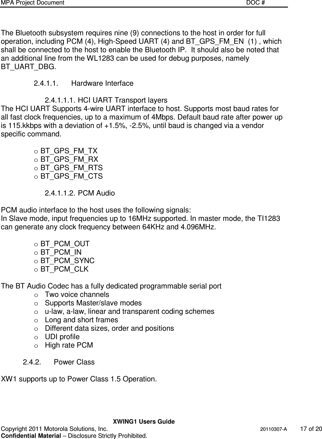
![MPA Project Document 70-147018-01 REV A Copyright 2011 Motorola Solutions, Inc. 20110307-A i Confidential Material – Disclosure Strictly Prohibited. Title: XWING1 Users Guide Description/Abstract/Synopsis: The purpose of this document is to provide a user’s and integrator’s guide targeted for module integrators Motorola Solutions Document Number: Agile Released Revision #: Document Status: In Progress 70-XXXXXX-01 [ ] – Released Version MPA Document Number: 0 [ ] – Next Release In Process NA Division: Sub-team: [ ] – Document Obsolete Working Revision: XXXXX- MCD RF-SYS Obsolete Document Replaced By: Last Updated: 06/17/2011 Document Type: SPEC / IG N/A Confidentiality Statement: Classification: N/A [ x ] - Contains Motorola Solutions partner NDA related material (Disclosure requires a three-way NDA.) Partner Name Agreement Number [x] - For Motorola Solutions Internal Use Only [ ] - Disclosure allowed under Motorola Solutions NDA Only [x] - Does or may contain Motorola Solutions patentable property *** Direct this document’s disclosure inquires to (Job Title): TNT Archive Location/Path: Agile Current Owner: Giovanni Ritieni Authors / Contributors: Kevin Lamb](https://usermanual.wiki/Zebra-Technologies/XWING1/User-Guide-1531379-Page-1.png)
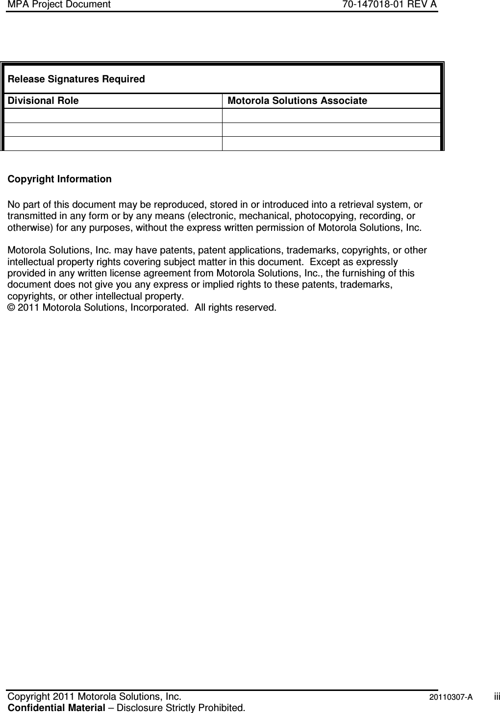
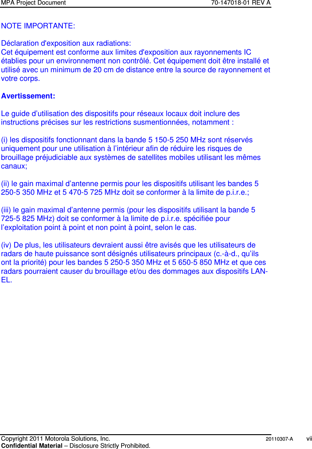
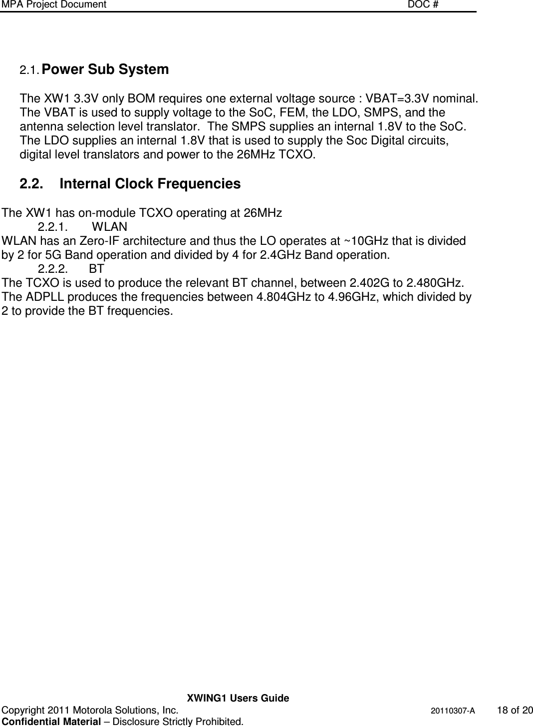
![MPA Project Document DOC # XWING1 Users Guide Copyright 2011 Motorola Solutions, Inc. 20110307-A 14 of 20 Confidential Material – Disclosure Strictly Prohibited. Accepts 19.2, 26, 38.4, 52-MHz reference clock Inputs for easy integration into cellular handsets IEEE Std 802.11d,e,h,i,k,r,s PICS compliant Supports Cisco Client eXtensions (CCX) standard Supports serial debug interface Supports Secure Digital Input/Output (SDIO) Serial Peripheral Interface (SPI) Host Interfaces Medium-Access Controller (MAC) – Embedded ARM™ Central Processing Unit (CPU) – Hardware-Based Encryption/Decryption Using 64-, 128-, and 256-Bit WEP, TKIP or AES Keys, – Supports requirements for Wireless Fidelity (Wi-Fi) Protected Access (WPA and WPA2.0) and IEEE Std 802.11i [Includes Hardware-Accelerated Advanced-Encryption Standard (AES)] – Designed to Work With IEEE Std 802.1x for Virtual Private Network (VPN) Solutions Baseband Processor – IEEE Std 802.11n single-stream data rates (MCS0-7) and SGI support 2.4/5.0 GHz Radio – Digital Radio Processor (DRP) implementation – Internal LNA – Supports : IEEE Std 802.11a, 802.11b, 802.11g, 802.11b/g and 802.11n 1.4.2. Bluetooth Bluetooth 1.1, 1.2, 2.0+EDR and 2.1+EDR specification compliant (Lisbon release) - up to HCI level. BT Enhanced Data Rate (2 and 3 Mbps) Enhanced host interfaces (UART, btSPI) Very low power consumption On-chip Embedded radio – Integrated 2.4 GHz RF transceiver – All digital PLL transmitter with digitally controlled oscillator – Near zero IF architecture – On-chip TX/RX switch – Support for Class-1.5 applications Embedded ARM Microprocessor System – High rate four wire UART HCI (H4) and Three Wire UART HCI (H5) – Automatic clock-detection mechanism Flexible PCM and I2S interfaces: full flexibility for data order, sampling and positioning Temperature detection and compensation mechanism ensures minimal variation in the RF performance over the entire temperature range TI-proprietary low-power scan achieves paging and inquiry scans at 1/3 normal power. Digital Radio Processor (DRP) single-ended 50 I/O for easy RF interfacing Patch trap mechanism and reserved RAM enables easy bug fixes Advance Audio Interfaces and capabilities – A2DP support – A2DP internal loopback – Wide-Band Speech support – On board SBC encoder/decoder - offloads host for A2DP and WideBand speech processing](https://usermanual.wiki/Zebra-Technologies/XWING1/User-Guide-1531379-Page-14.png)
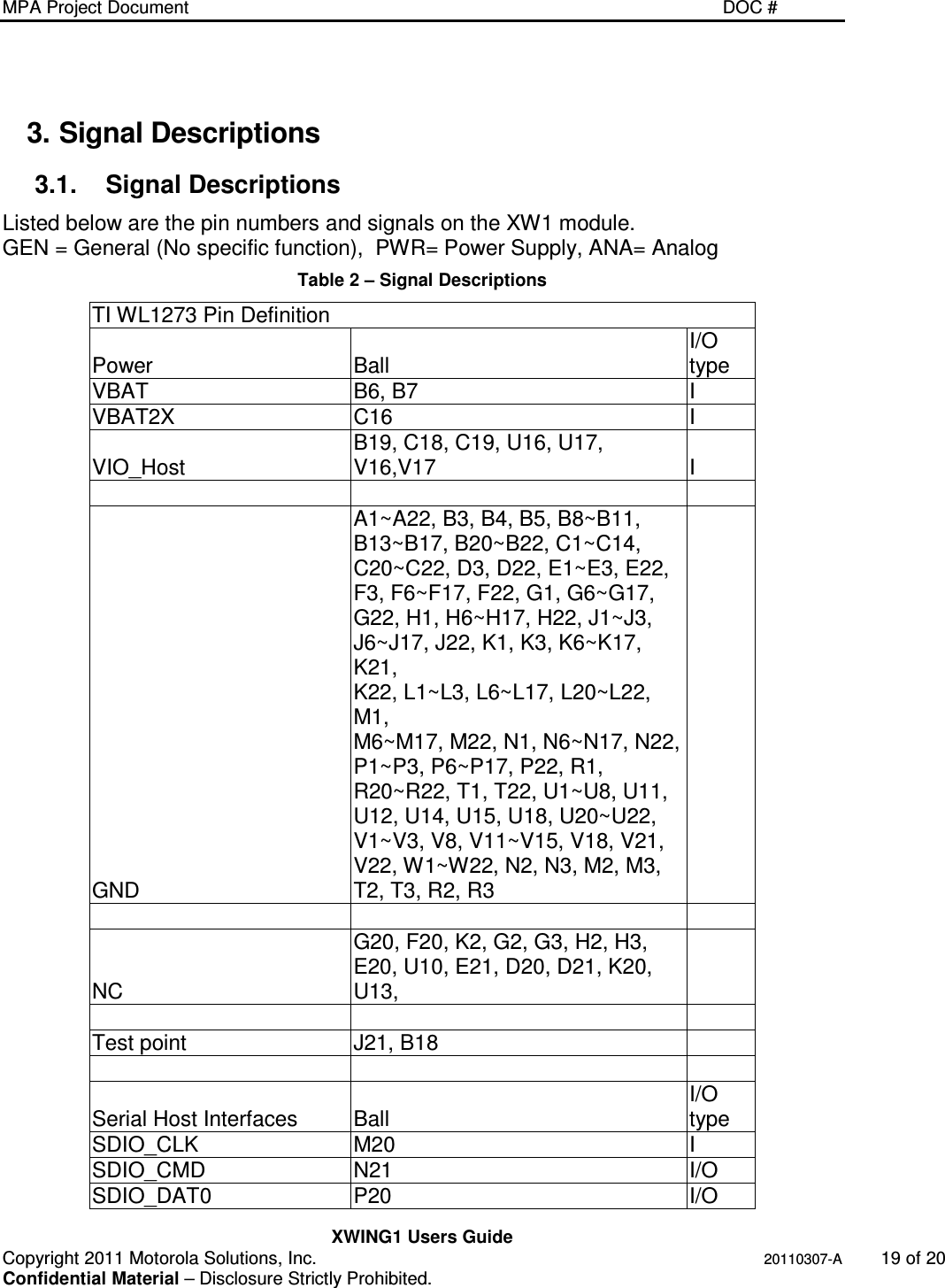
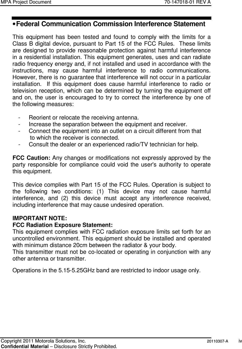
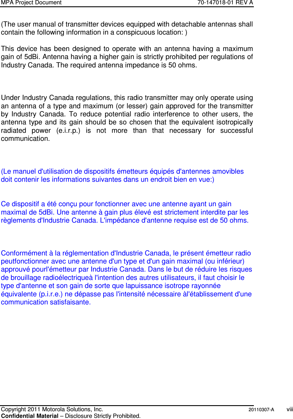
![MPA Project Document DOC # XWING1 Users Guide Copyright 2011 Motorola Solutions, Inc. 20110307-A 16 of 20 Confidential Material – Disclosure Strictly Prohibited. 2.3. WLAN 2.3.1. Host Communications The WLAN core requires a total of eight (8) dedicated signals in order to communicate to the host processor. The WLAN core is enabled via the WL_EN signal (1) and communicates to the host processor via SDIO (6) with an additional interrupt signal WL_IRQ(1). 2.3.1.1. Hardware Interface The interface between the host and the XW1 Module is a standard SDIO interface (see SDIO spec version 2.0), supporting maximum clock rate of 25MHz. 2.3.2. WLAN MAC The TI1273 MAC implements the IEEE standard 802.11 MAC via an Embedded ARM™ Central Processing Unit (CPU) – Hardware-Based Encryption/Decryption Using 64-, 128-, and 256-Bit WEP, TKIP or AES Keys, – Supports requirements for Wireless Fidelity (Wi-Fi) Protected Access (WPA and WPA2.0) and IEEE Std 802.11i [Includes Hardware-Accelerated Advanced-Encryption Standard (AES)] – Designed to Work With IEEE Std 802.1x for Virtual Private Network (VPN) Solutions 2.3.3. WLAN Baseband Processor The TI1273 baseband processor is situated between the on-chip MAC and radio. IEEE Std 802.11n single-stream data rates (MCS0-7) and SGI support 2.3.4. RF Architecture 2.3.4.1. XW1 WLAN RF Paths The XWING1 expands upon the Texas Instrument WiLink 6.0 (WL1273) reference design to accommodate the MPA2’s WLAN diversity requirements. The XW1 module has tightly integrated some additions / deviations to this reference design. The 5GHz BPF has been replaced by a diplexer and the combined 2.4/5GHz RF path is switched between two RF ports. This solution provides transmit and receive antenna-selection-diversity between two dual-band RF ports. 2.4. Bluetooth 2.4.1. Host Communications](https://usermanual.wiki/Zebra-Technologies/XWING1/User-Guide-1531379-Page-16.png)