Zhejiang Dahua Vision Technology DH-SD12D network PTZ Camera User Manual 2
Zhejiang Dahua Vision Technology Co., Ltd network PTZ Camera Users Manual 2
Contents
- 1. Users Manual-1
- 2. Users Manual-2
Users Manual-2
92
Step 2
Click “Add” which is located on the upper right corner of the interface, and then it will add tour path.
Step 3
Click “Add” which is located on the lower right corner, and then it will add several presets.
Step 4
Implement relevant operation upon the tour.
Double click “Tour Name” to modify the name of the tour.
Double click “Duration” to set duration for each preset.
Step 5
Click “Start” to start tour.
Note
The device will stop tour if PTZ is operated during tour.
Step 6
Click “Stop” to stop tour.
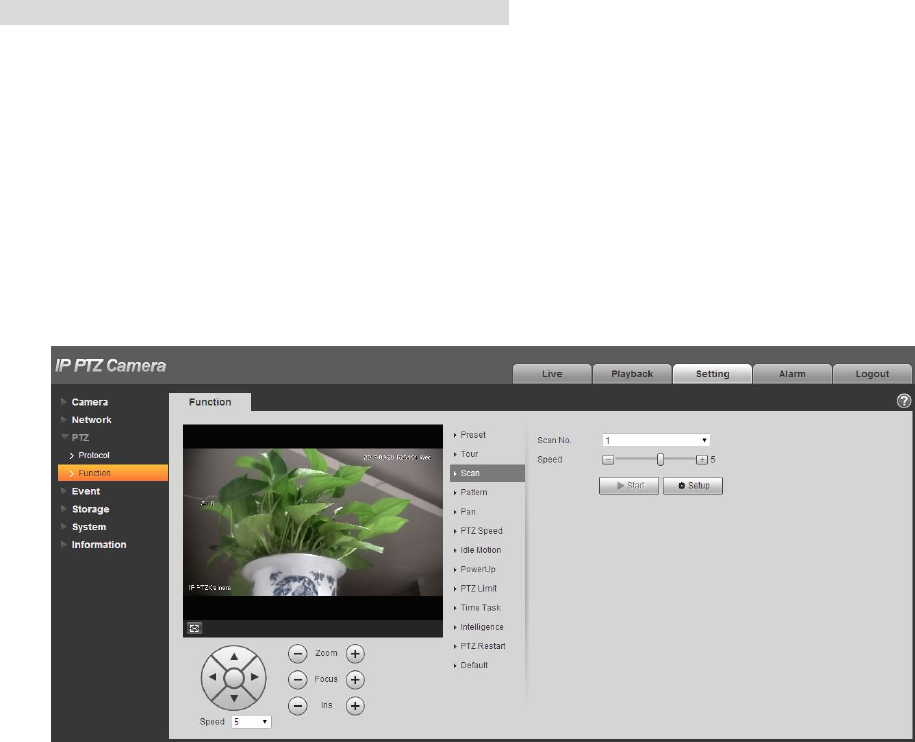
4.3.2.3 Scan
Scan means the speed dome scanning back and forth within the left and right limit with a certain speed.
Step 1
Select “Setup > PTZ Setting > Function > Scan”.
The system will display the interface of “Scan”, which is shown in Figure 4-66.
Step 2
Click San No.
Figure 4-66
Step 3
Drag Speed bar and set scan speed.
93
Step 4
Click “Setup”, adjust the camera direction to make it reach proper location.
Step 5
Click “Set Left/Right Limit” to set the location as the “Left/Right Limit” of the camera.
Step 6
Click “Start” to start scan.
Step 7
Click “Stop” to stop scan.
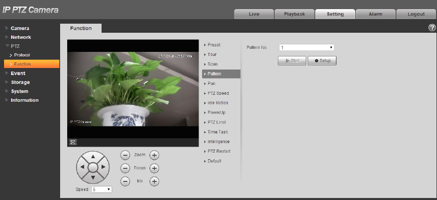
4.3.2.4 Pattern
Pattern can continuously record the operations implemented upon the device, such as pan, tilt, zoom,
call preset and etc. You can directly call the pattern after it is saved completely.
Step 1
Select “Setup > PTZ Setting > Function > Pattern”.
The system will display the interface of “Pattern”, which is shown in Figure 4-67.
Figure 4-67
Step 2
Select Pattern No.
Step 3
Click “Setup” and click “Start Rec‟, operate the PTZ according to the actual needs.
Step 4
Click “Stop Rec” to complete recording.
Step 5
Click “Start” to start pattern.
Step 6
94
Click “Stop” to stop pattern.
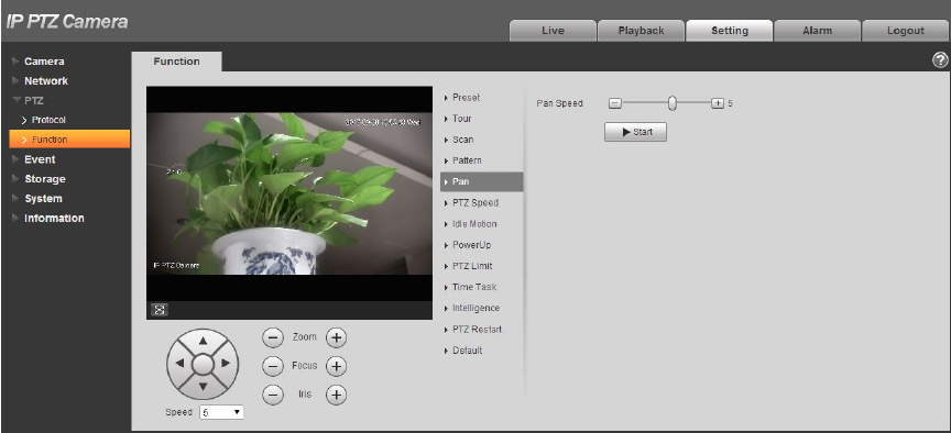
4.3.2.5 Pan
Pan means the speed dome rotating continuously 360°horizontally with a certain speed.
Step 1
Select “Setup > PTZ Setting > Function > Pan”.
The system will display the interface of “Pan”, which is shown in Figure 4-68.
Figure 4-68
Step 2
Drag speed bar and set “Pan Speed”
Step 3
Click “Start” to make the PTZ rotate horizontally with the speed you just set.
Step 4
Click “Stop” to stop pan.
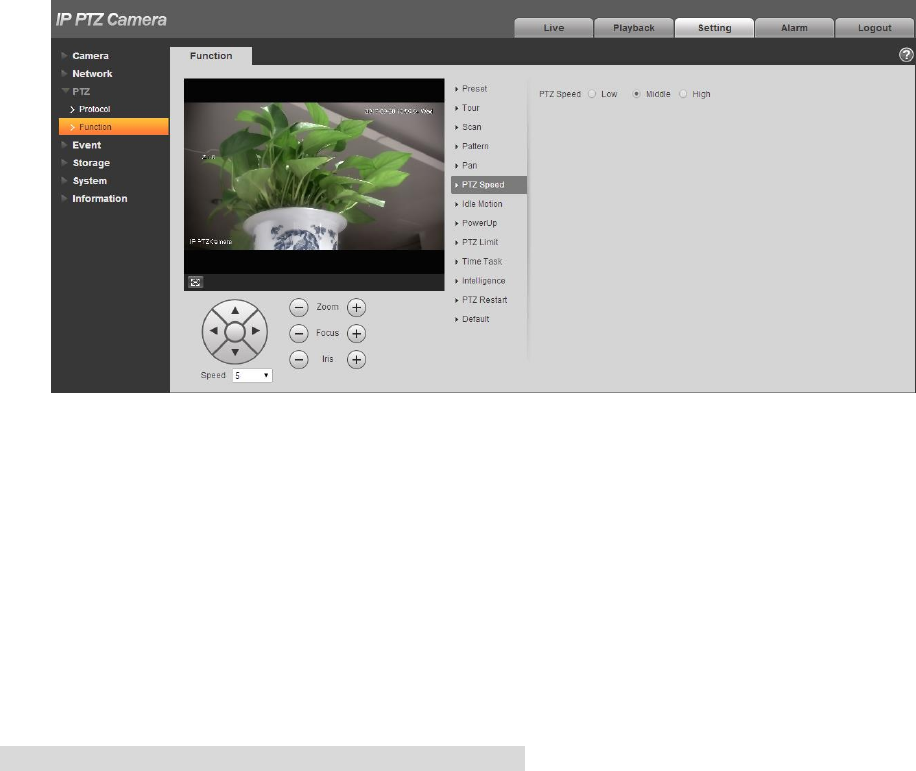
4.3.2.6 PTZ speed
PTZ speed means the rotation speed of the device.
Step 1
Select “Setup > PTZ Setting > Function > PTZ Speed”.
The system will display the interface of “PTZ Speed”, which is shown in Figure 4-69.
95
Figure 4-69
Step 2
Select “PTZ speed”, it is “Middle” by default.
The system will make the PTZ rotate with the speed you just set.
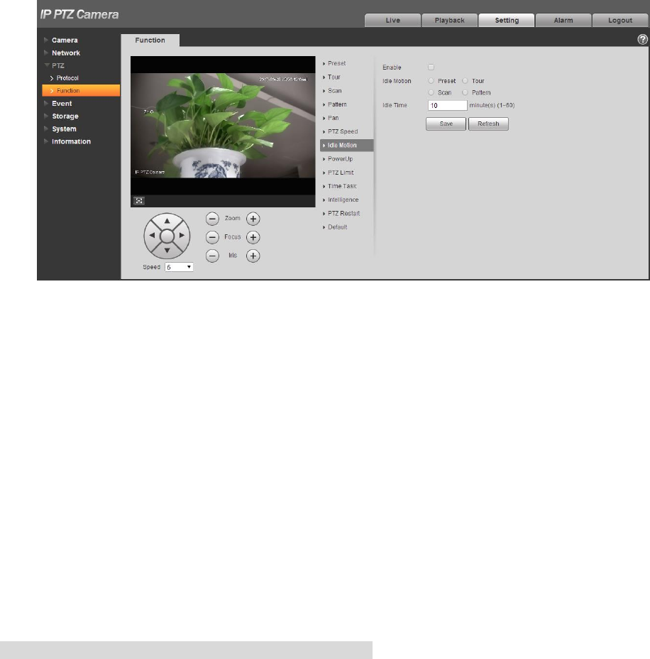
4.3.2.7 Idle Motion
Idle motion means the device implementing the behavior which is set in advance when it is not receiving
any valid command within the set time.
Note
It needs to set preset, tour, scan and pattern in advance.
Step 1
Select “Setup > PTZ Setting > Function > Idle Motion”.
The system will display the interface of “Idle Motion”, which is shown in Figure 4-70.
96
Figure 4-70
Step 2
Select “Enable” to enable idle motion function.
Step 3
Select types of idle motion, which are preset, tour, scan or pattern.
Step 4
Select the number of idle motion.
Step 5
Set the idle time of the selected motion.
Step 6
Click “Save” to complete config.
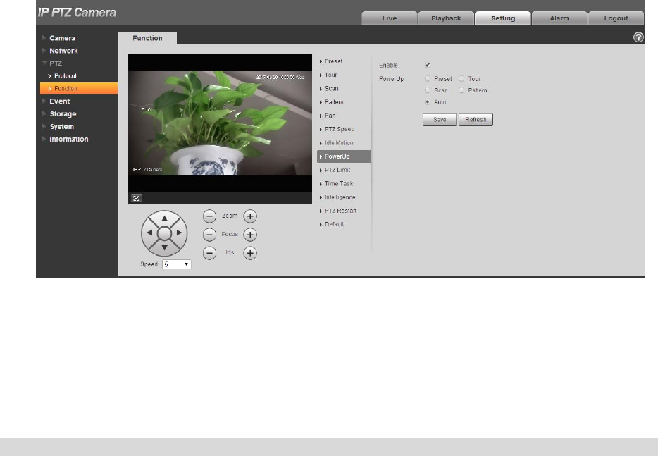
4.3.2.8 Power Up
It means the motion which is auto operated by the device after it is powered up.
Note
It needs to set preset, tour, scan and pattern in advance.
Step 1
Select “Setup > PTZ Setting > Function > Power up”, which is shown in Figure 4-71.
97
Figure 4-71
Step 2
Select “Enable” to enable PowerUp functions.
Step 3
Select the types of PowerUp; you can select preset, tour, scan, pattern or auto.
Note
The system will implement the last action before the camera‟s power is cut off when selecting “Auto”.
Step 4
Select the number of action type.
Step 5
Click “Save” to complete config.
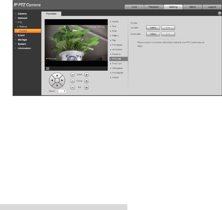
4.3.2.9 PTZ Limit
PTZ limit function is used to set the movement area of the device, which makes the device move within
area.
Step 1
Select “Setup > PTZ Setting > Function > PTZ Limit”.
The system will display the interface of “PTZ Limit”, which is shown in Figure 4-72.
98
Figure 4-72
Step 2
Select “Enable” to enable PTZ Limit function.
Step 3
Control camera direction; click “Setting” to set up line.
Step 4
Control camera direction; click “Setting” to set down line.
Step 5
Click “Live” to preview the up line and down line which is already set.
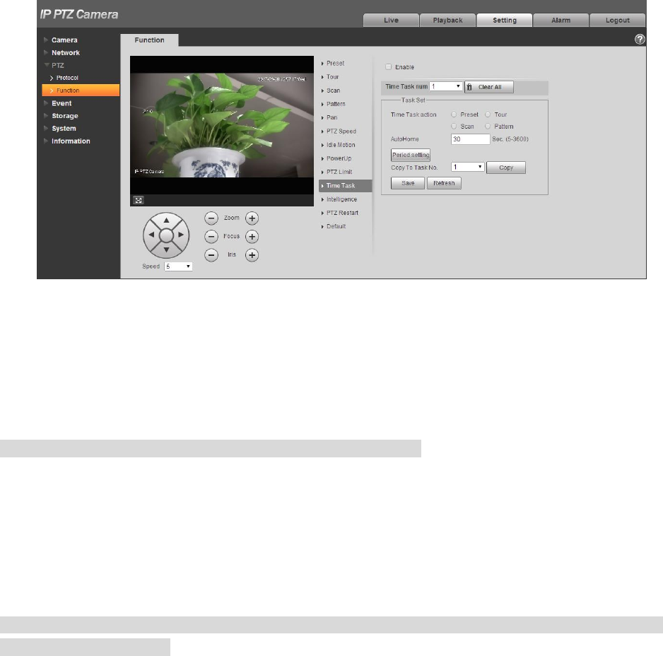
4.3.2.10 Time Task
Time task is to implement relevant movements within the set period.
Note
It needs to set preset, tour, scan and pattern in advance.
Step 1
Select “Setup > PTZ Setting > Function > Time Task”.
The system will display the interface of “Time Task”, which is shown in Figure 4-73.
99
Figure 4-73
Step 2
Select “Enable” to enable the function of time task.
Step 3
It is to set the number of time task.
Note
Click “Clear All” to delete all the time tasks which have been set.
Step 4
Select time take action, you can select preset, tour, scan or pattern.
Step 5
Select action number.
Step 6
Set the time of auto home.
Note
Auto home time means the time it needs to take to auto recover time task when manually calling PTZ
and interrupting time task.
Step 7
Click “Period Setting” to set the period of implementing time task.
Step 8
Click “Copy” and select task number, then you can copy it to the task whose number has been selected.
Step 9
Click „Save” to complete config.
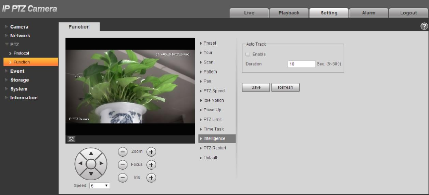
4.3.2.11 Intelligence
It is to set the tracking duration of the camera. The config steps are shown as follows:
100
Step 1
Select “Setup > PTZ > Function > Intelligence” and the system will display the interface of “Intelligence”,
which is shown in Figure 4-74.
Figure 4-74
Step 2
Select “Enable” to enable auto tracking function.
Step 3
Input the duration of auto tracking.
Step 4
Click “Save” to complete config.
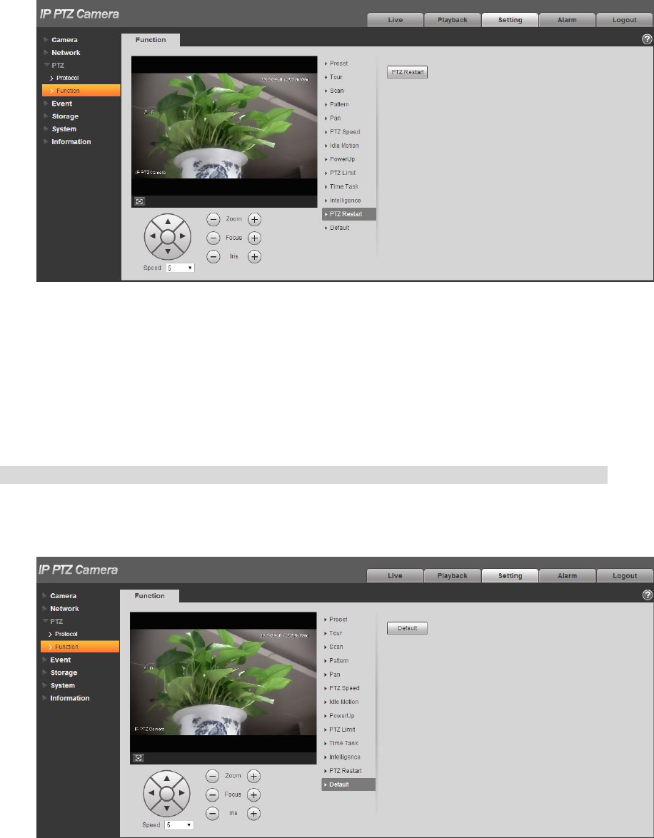
4.3.2.12 PTZ Restart
Step 1
Select “Setup > PTZ Setting > Function > PTZ Restart”.
The system will display the interface of “PTZ Restart”, which is shown in Figure 4-75.
101
Figure 4-75
Step 2
Click “PTZ Restart” and the system will restart PTZ.
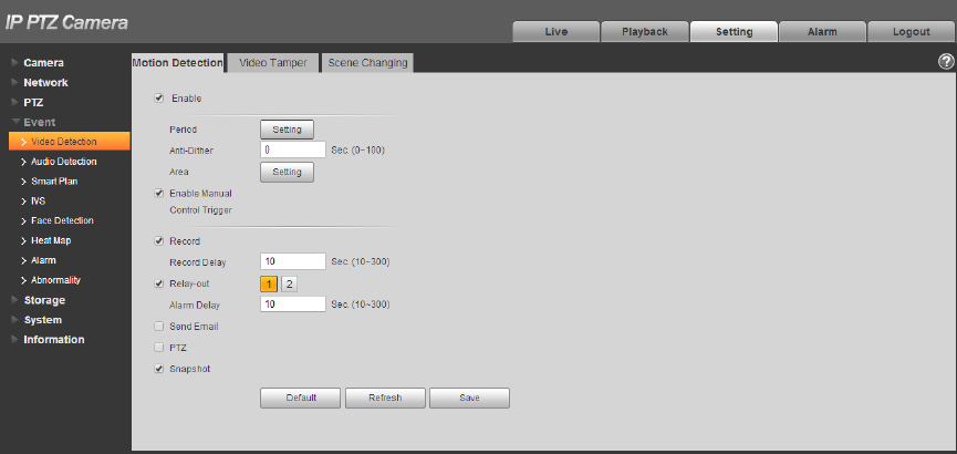
4.3.2.13 Default
The function can recover default settings of the PTZ. The config steps are shown as follows:
Note
The function will delete all the PTZ config made by users, please operate after confirmation.
Step 1
Select “Setup > PTZ Setting > Function > Default”.
The system will display the interface of “Default”, which is shown in Figure 4-76.
102
Figure 4-76
Step 2
Click “Default” to recover all the default settings.
4.4 Event
4.4.1 Video Detection
Video detection includes motion detection, video tamper and scene changing. The config steps are
shown as follows.
4.4.1.1 Motion Detection
Step 1
Select “Setup > Event > Video Detection > Motion Detection”.
The system will display the interface of “Motion Detect”, which is shown in Figure 4-77.
Figure 4-77
Step 2
Click “Enable” and configure info of each parameter according to the actual needs.
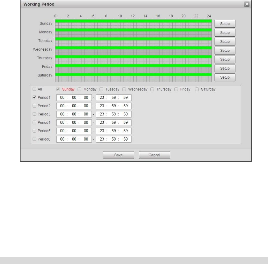
Set working period.
Click “Setup”, and it will display the interface of working period in Figure 4-78.
103
Figure 4-78
Set alarm period, it can enable alarm event within the range of set period.
There are totally six periods to set every day, click the check box in front of the period, and then the
period can be valid.
Select week number (default is Sunday, if users select the whole week, it means setting can be
applied to the whole week; users can also select the check box in front of the day to make separate
setting for some days).
Click “Save” button after setup, return to motion detect page.
Note
You can also set working period via pressing left mouse button and dragging it on the setup interface.
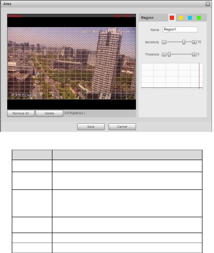
Set area
Click “Setup” and you can set area in the interface shown in Figure 4-79.
Different colors represent different areas. Each area can set different detection zones. Detection zone
can be irregular and discontinuous.
104
Figure 4-79
Parameter
Function
Name
Default area name includes Region 1, Region 2, Region 3,
Region 4 and custom.
Sensitivity
It is sensitivity of brightness as motion detection is more possible
to be trigger with high sensitivity. You can set up to four areas.
The range is 0~100. The recommenced value is 30~70.
Area threshold
It is to check target object area related to detection area. The
lower the area threshold, the easier to trigger motion detection.
You can set up to four areas. The range is 0~100. The
recommenced value is 1~10.
Waveform
Red means motion detection is triggered. Green means motion
detection is not triggered.
Delete all
Clear all areas.
Delete
Delete selected area.
Table 4-23
Other parameters

105
Parameter
Function
Anti-dither
System only memorizes one event during the anti-dither period. The
unit is second, the value ranges from 0s to 100s.
Manual Control
Excluded
Click it and it will generate motion detection event when excluding
manual control, which can reduce the false alarm rate of motion
detection event.
Record
Check it and so when alarm occurs, system will auto record. You
shall set record period in Storage>Schedule and select auto record
in record control interface.
Record Delay
System can delay the record for specified time after alarm ended.
The value ranges from 10s to 300s.
Relay out
Check it to enable alarm activation output port, it can activate
corresponding alarm output device when alarm occurs.
Alarm delay
It means alarm delays a period of time to stop after alarm ends, the
unit is second, and the value ranges from 10s to 300s.
Send Email
If you enabled this function, System can send out email to alert you
when alarm occurs. User can set email address in Network>SMTP.
PTZ
Here you can set PTZ movement when alarm occurs. Such as
go to preset x when there is an alarm.
The event type includes: preset, tour and pattern.
Snapshot
You need to check the box here so that system can backup motion
detection snapshot file. You shall set snapshot period in
Storage>Schedule.
Table 4-24
Step 3
Click “Save” to complete config.
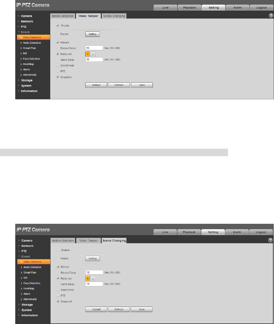
4.4.1.2 Video Tamper
Step 1
Select “Setup > Event > Video Detect > Video Tamper”.
The system will display the interface of “Video Tamper”, which is shown in Figure 4-80.
106
Figure 4-80
Step 2
Click “Enable” and configure info of each parameter according to the actual needs.
Note
Please refer to “4.4.1.1 Motion Detection” for more details about parameter config.
Step 3
Click “Save” to complete config.
4.4.1.3 Scene Changing
Step 1
Select “Setup > Event > Video Detection > Scene Changing”. The system will display the interface of
“Scene Changing”, which is shown in Figure 4-81.
Figure 4-81
Step 2
Click “Enable” and then configure parameter info according to the actual requirements.
107
Note
Please refer to “4.4.1.1 Motion Detection” for more details about parameter config.
Step 3
Click “Save” to complete configuration.
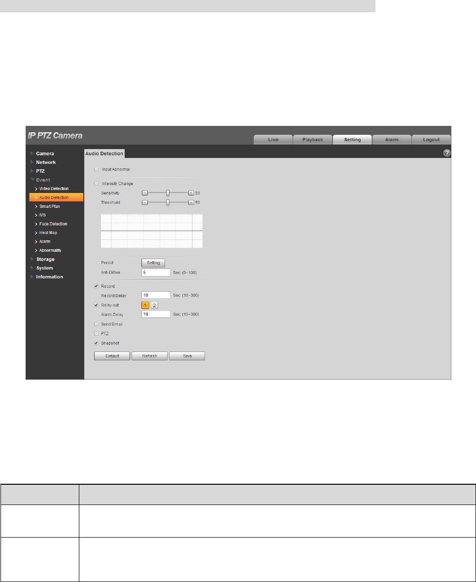
4.4.2 Audio Detection
Step 1
Select “Setup > Event > Audio Detection”.
The system will display the interface of “Audio Detection”, which is shown in Figure 4-82.
Figure 4-82
Step 2
Configure info of each parameter according to the actual needs; please refer to the following sheet for
more details.
Parameter
Function
Enable Input
Abnormal
Check “Enable Input Abnormal” and it will activate alarm when detecting audio input
abnormal.
Enable
Intensity
Change
Check “Enable Intensity Change” and it will activate alarm when detecting audio
intensity change surpass threshold.
108
Parameter
Function
Sensitivity
Levels range from1 to100 and adjustable, the smaller the value, it means the input
sound volume change surpassing continuous environment volume and it can be
judged as audio abnormal, users can adjust according to the actual environment
testing.
Threshold
Levels range from 1 to 100 and adjustable, which is used to set filtered environment
sound intensity. If the environment noise is bigger, users need to set the value
higher. Besides, users can adjust it according to the actual environment testing.
Table 4-25
Note
Please refer to “4.4.1.1Motion Detection” for description of other parameters.
Step 3
Click “Save” to complete config.
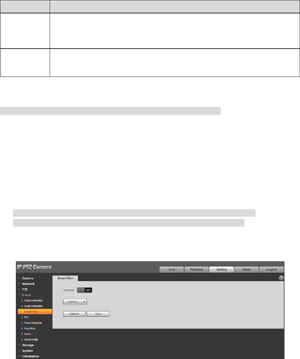
4.4.3 Smart Plan
Statistics intelligent functions such as heat map, people counting can‟t coexist with the intelligent
functions related to preset, it needs users to select first. Each preset can set different intelligent function,
the corresponding setting can be valid only when it selects exact intelligent function.
Note
It needs to set preset in advance, please refer to “4.3.2.1 Preset” for setting method.
Heat map and preset are added plans, which can‟t be enabled at the same time.
Step 1
Select “Setup > Event > Smart Plan”. The system will display the interface of “Smart Plan”, which is
shown in Figure 4-83.
Figure 4-83

109
Step 2
Enable corresponding intelligent functions according to the requirements.
Enable heat map or face detection function.
1. Click the sliding block in to enable the function switch.
2. Click heat map or face detection function to enable corresponding intelligent functions. The selected
intelligent function appears to be bright, click it to cancel the selected intelligent function.
Enable IVS, face detection function.
1. Select preset in the “Add Plan”. The system will display corresponding plan of the preset.
2. Click IVS, face detection to enable corresponding functions.
Step 3
The selected intelligent function appears to be bright, you can click it to cancel the function.
4.4.4 IVS
Basic requirements for scene selection:
The total proportion of the target shall not exceed 10% of the image.
The target size in the image shall not be less than 10 pixel ×10 pixel, the size of abandoned target
shall be less than 15 pixel ×15 pixel (CIF image); the width of target shall be less than one third of
the image; it is recommended that the target height shall be around 10% of the image.
The brightness value of target and background shall be no less than 10 gray levels.
It has to guarantee that the target has to appear at least more than 2 seconds in the view, the
movement distance exceeds the width of the target itself and it is no less than 15 pixels (CIF
image).
Try to lower the complexity of the monitoring analysis scene if possible; It is not recommended to
use intelligent analysis functions in the scene where the target is very crowded and light changes
frequently.
Try to keep away from glass, ground reflect light, water surface and other areas; try to keep away
from branches, shadow and mosquito interference area; try to keep away from backlight scene,
avoid direct light.
Note
It needs to set preset in advance, please refer to “4.3.2.1 Preset” for more details about preset
setting.
Heat map and intelligent function added by preset can‟t be enabled at the same time.
4.4.4.1 IVS
Step 1
Select “Setup > Event > Intelligent Behavior > Config”.
The system will display the interface of “Rule Config”, which is shown in Figure 4-84
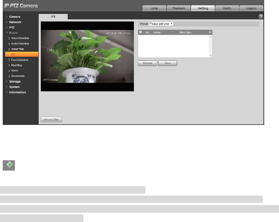
110
Step 2
Select the preset which needs to be configured with intelligent rules.
Figure 4-84
Step 3
Click to add intelligent rules.
Note
Double click “Rule Type” to modify the type of rules.
Enter rule config interface, the lock function is enabled automatically, the locking time is 180s,
during this period, other control modes are invalid except manual control over the speed dome. You
can click “Unlock” to unlock it.
Step 4
Click “Save” to complete config.
4.4.4.1.1 Tripwire
It will trigger alarm when the target crosses the warning line according to the set movement direction.
It needs some time and space to confirm the target after it appears, so it needs to leave some space on
both sides of the warning line when setting warning line, please don‟t set it near the obstacle.
Application scene: it can only be applied to the scene where the target is sparse and it is basically
blocked between targets, such as the perimeter protection area without security guard.
The config steps are shown as follows:
Step 1
Select rule type as “Tripwire” and the config interface is shown in Figure 4-85.
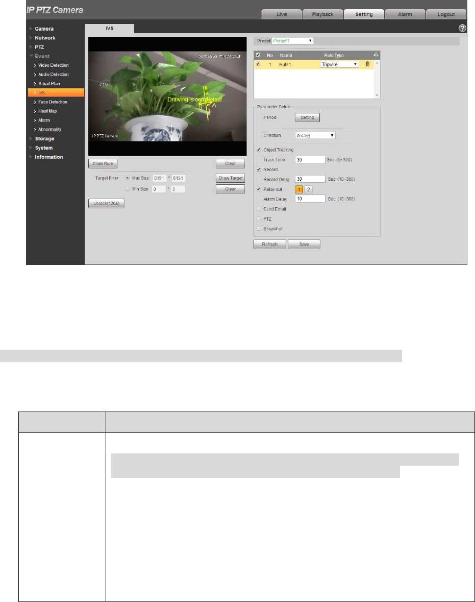
111
Figure 4-85
Step 2
Click “Draw Rule” and draw rules in the monitoring image.
Note
Click “Clear” on the right of “Draw Rule” to clear all the rules which have been drawn.
Step 3
Configure parameter info according to the actual needs. Please refer to Table 4-26 for more details.
Parameter
Note
Working period
Note
Set alarm period, it can enable alarm event within the range of set period.
Click “Setup” to pop out setting interface of “Working Period”.
You can input time number value or press the left mouse button, and
drag on the setting interface directly.
There are totally six periods to set every day, click the check box in
front of the period, and then the period can be valid.
Select week number (default is Sunday, if users select the whole
week, it means setting can be applied to the whole week; users can
also select the check box in front of the day to make separate setting
for some days).
Click “Save” button after setup is completed, return to rule config setting
interface, click “Save” to complete period setting of tripwire.

112
Parameter
Note
Direction
It is set the direction of tripwire, you can select A→B、B→A、A↔B.
Alarm track
Check it and it will generate alarm track when the target triggers intelligent
rules.
Track time
It is to set the time of track time.
Record
Check it and so when alarm occurs, system will auto record. You shall set
record period of alarm in “Storage>Schedule” and select auto record in
record control interface.
Record delay
System can delay the record for specified time after alarm ended. The
value ranges from 10s to 300s.
Relay out
Check it to enable alarm activation output port, it can activate
corresponding alarm output device when alarm occurs.
Alarm delay
It means the alarm delays a period of time to stop after alarm ends, the unit
is second, and the value ranges from 10s to 300s.
Send Email
Check it and the system can send out email to inform users when alarm
occurs. User can set email address in “Network>SMTP (email)”.
PTZ
Here you can set PTZ movement when alarm occurs. Such as go to preset
x when there is an alarm.
The event type includes: preset, tour and pattern.
Snapshot
Check it and the system can realize alarm snapshot automatically when
alarm occurs, meanwhile it needs to set snapshot period of alarm in “
Storage>Schedule”.
Target filter
Check some intelligent rule, click “Draw Target”, then you can draw the
model of filter target according to the rule in the scene. Click “Clear” to
delete all the target filter models which have been drawn.
Table 4-26
Step 4
Click “Save” to complete config.
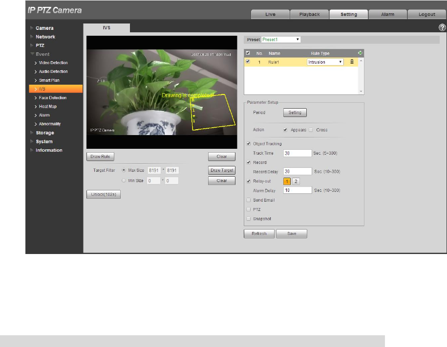
4.4.4.1.2 Intrusion
Intrusion includes cross area and in area functions.
Crossing area means that it will trigger alarm when target entering or leaving area.
113
In area function means that it will trigger alarm when certain amount of target appear in the
designated area within specific time. In area function is only responsible for the statistics of the
target quantity in the detection area without considering whether the target is the same or not.
As for the report interval of the in area function, the system can detect if the same event will occur
within the interval after triggering the first alarm, the alarm counter will clear itself if no same event
occurs during the period.
As it is similar to the warning line, it also needs to leave some movement space for the target out of the
area line if it is to detect enter and leave events
Application scene: It can only be applied to the scene where the target is sparse and it is basically
mutually blocked between targets, such as the perimeter protection area without security guard.
The config steps are shown as follows:
Step 1
Select the rule type as “Intrusion” and the config interface is shown in Figure 4-86.
Figure 4-86
Step 2
Click “Draw Rule” to draw rules in the monitoring image.
Note
Click “Clear” on the right of “Draw Rule” to clear all the rules which have been drawn.
Step 3
Configure parameter info according to the actual needs. Please refer to Table 4-27 for more details.
114
Parameter
Note
Action
It is to set the actions of intrusion, you can select appear and cross.
Direction
It is to set the direction of cross area, you can select enter, leave, enter &
leave.
Table 4-27
Please refer to “4.4.4.1.1 Tripwire” for more details about other parameters.
Step 4
Click “Save” to complete config.
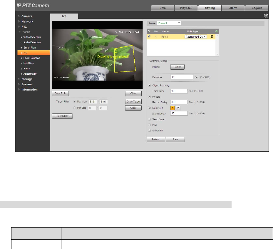
4.4.4.1.3 Abandoned Object
It means triggering alarm when the abandoned object exceeds the time set by users in the monitoring
scene.
Abandoned and missing object detection can be confusing in a situation where foreground and
background is both very complex.
It will trigger alarm when pedestrians or vehicles stay still for a long time, which is considered as
abandoned object. In order to filter this kind of alarm, generally the abandoned object is smaller than
person and vehicle; therefore it can filter person and vehicle via setting filter size. Besides, it can avoid
false alarm of short stay for people via extending alarm time.
Application scene: It can be applied to the scene where the target sparse and there is no obvious and
frequent light change. As for the scene with high target density and frequent blocking, alarm leakage will
increase; as for the scene with more people to stay, false alarm will increase. As for the detection area,
it is required to be simple; it can‟t be applied to complicated areas.
The config steps are shown as follows:
Step 1
Select rule type as “Abandoned Object” and the config interface will be shown in Figure 4-87.
115
Figure 4-87
Step 2
Click “Draw Rule” to draw rules in the monitoring image.
Note
Click “Clear” on the right of “Draw Rule” to clear all the rules which have been drawn.
Step 3
Configure parameter info according to the actual needs. Please refer to Table 4-28 for more details.
Parameter
Note
Duration
It is to set the shortest time from object abandoned to trigger alarm.
Table 4-28
Please refer to “4.4.4.1.1 Tripwire” for more details about other parameters.
Step 4
Click “Save” to complete config.
4.4.4.1.4 Missing Object
It means it will trigger alarm after the target in the scene is taken and exceeds a certain period of time.
The system will make statistics for the still areas in the foreground area, and distinguish whether it is
missing object or abandoned object according to the similarity between foreground and background, it
will trigger alarm when it exceeds the time set by users.

116
It may cause mistake when distinguishing abandoned object from missing object when both foreground
and background are very complex.
Application scene: It can be applied to the scene where the target sparse and there is no obvious and
frequent light change. As for the scene with high target density and frequent blocking, alarm leakage will
increase; as for the scene with more people to stay, false alarm will increase. As for the detection area,
it is required to be simple; it can‟t be applied to complicated areas.
The config steps are shown as follows:
Step 1
Select rule type as “Missing Object” and the config interface is shown in Figure 4-88.
Figure 4-88
Step 2
Click “Draw Rule” to draw rules in the monitoring image.
Note
Click “Clear” on the right of “Draw Rule” to clear all the rules which have been drawn.
Step 3
Configure parameter info according to the actual needs. Please refer to Table 4-29 for more details.
Parameter
Note
Duration
It is to set the shortest time from object disappears to trigger alarm.
117
Table 4-29
Please refer to “4.4.4.1.1 Tripwire” for more details about other parameters.
Step 4
Click “Save” to complete config.
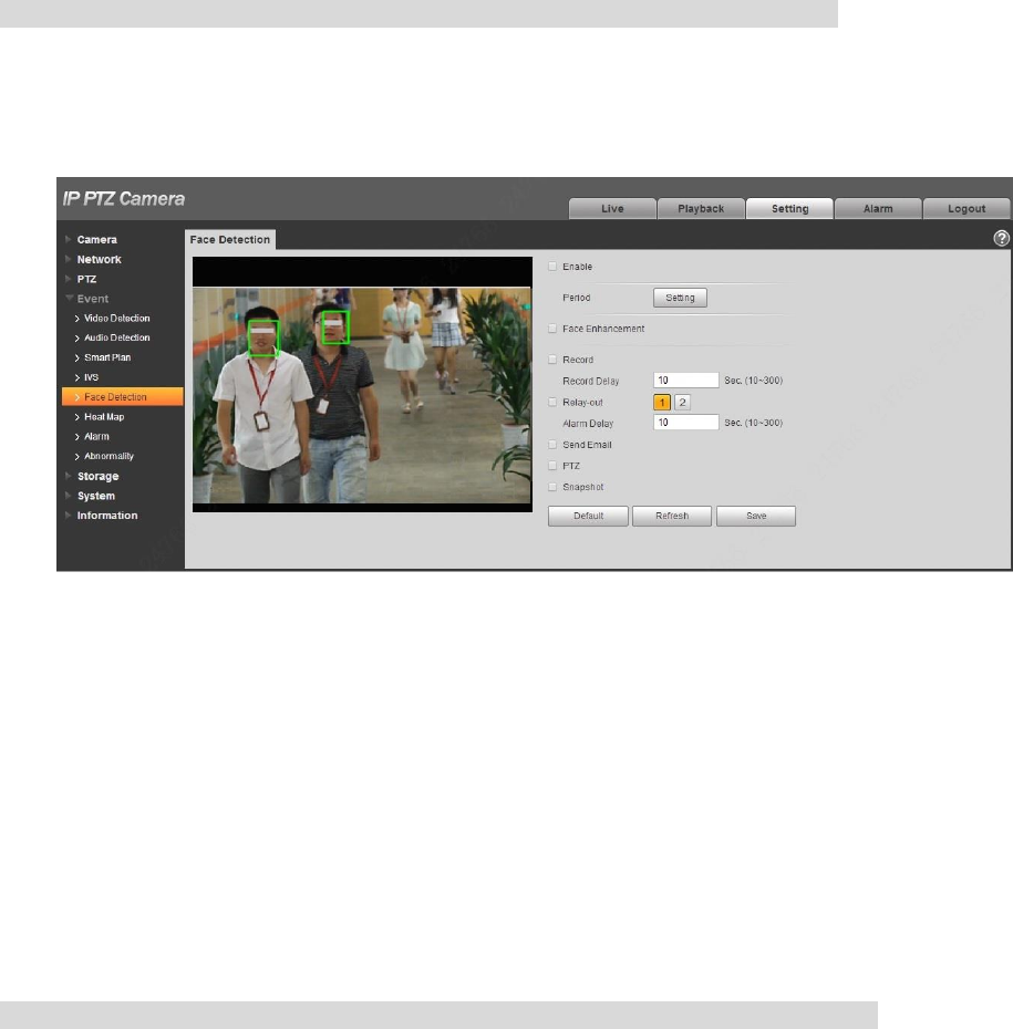
4.4.5 Face Detection
Note
It needs to add preset and enable the smart function before enabling the function.
You can detect face and make snapshot in complex environment via face detection function.
Step 1
Select “Setup > Event > Face Detect”.
The system will display the interface of “Face Detection”, which will be shown in Figure 4-89.
Figure 4-89
Step 2
Select “Enable” to enable face detection.
Step 3
Configure parameter info according to the actual needs. Please refer to “4.4.4.1.1 Tripwire” for more
details about other parameters.
Step 4
Click “Save” to complete config.
4.4.6 Heat Map
Note
It needs to add preset and enable the intelligent function before enabling the function.
118
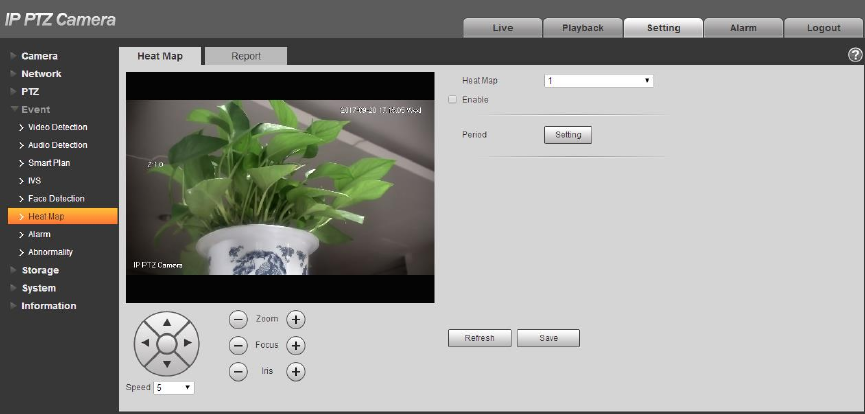
4.4.6.1 Heat Map
It is used to detect the activity level of moving object in the scene within a certain period of time.
Step 1
Select “Setup > Event > Heat Map > Heat Map”.
The system will display the interface of “Heat Map”, which is shown in Figure 4-90.
Figure 4-90
Step 2
Select the number of heat map.
Step 3
Select “Enable” to enable the function of heat map.
Step 4
Click “Setting” to set working period, please refer to “4.4.1.1 Motion Detection” for more details.
Step 5
Adjust the camera angle via the direction, zoom, focus and iris buttons which are located below the
image. Turn the camera to the heat map scene which needs to be checked.
Step 6
Click “Save” to complete setting.
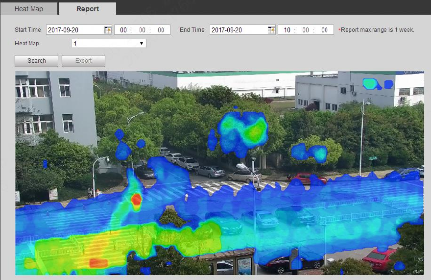
4.4.6.2 Report
It is to check the heat map statistics result of the scene within the selected period.
The config steps are shown as follows:
Step 1
Select “Setup > Event > Heat Map > Report” and the system will display the interface of “Report”.
Step 2
119
Select the start time and end time of heat map which needs to be searched.
Step 3
Select the number of heat map.
Step 4
It will display the search result on the interface after clicking “Search”, which is shown in Figure 4-91.
Figure 4-91
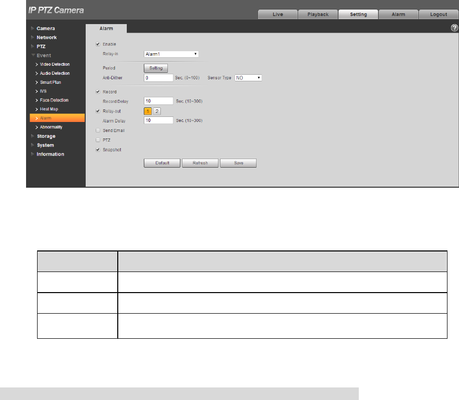
4.4.7 Alarm
Step 1
Select “Setup > Event > Alarm”.
The system will display the interface of “Alarm”, which is shown in Figure 4-92.
120
Figure 4-92
Step 2
Configure info of each parameter according to the actual needs; refer to Table 4-30 for more details.
Parameter
Function
Enable
After enabled, relay activation will work.
Relay-in
Select relay-in, it can select 7-channel relay in.
Sensor type
There are two options: NO/NC. Switch from NO to NC means
enabling alarm; Switch from NC to NO means disabling alarm.
Table 4-30
Note
Please refer to “4.4.1.1 Motion Detection” for description of other parameters.
Step 3
Click “Save” to complete config.
4.4.8 Abnormity
Abnormality includes six alarm events which are no SD card, capacity warning, SD card error,
disconnection, IP conflict and illegal access.
4.4.8.1 SD Card
Step 1
Select “Setup > Event > Abnormity > SD Card”.
The system will display the interface of “SD Card”, which is shown from Figure 4-93 to Figure 4-95.
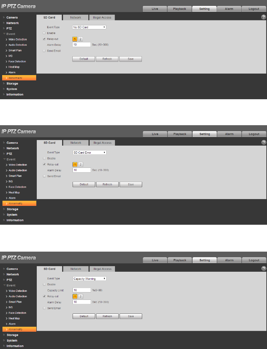
121
Figure 4-93
Figure 4-94
Figure 4-95
122
Step 2
Configure info of each parameter according to the actual needs; refer to Table 4-31 for more details.
Parameter
Function
Enable
Check to alarm when SD card is abnormal.
SD Card
Capacity
Lower
Limit
User can set SD card capacity percentage which is left. When SD card
space left is smaller than this, alarm occurs.
Table 4-31
Note
Please refer to “4.4.1.1 Motion Detection” for description of other parameters.
Step 3
Click “Save” to complete config.
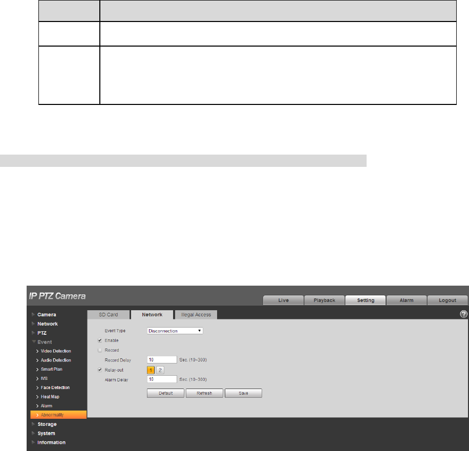
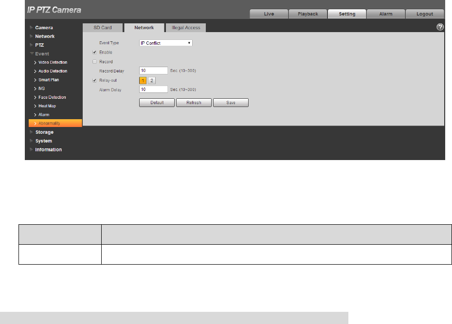
4.4.8.2 Network
Step 1
Select “Setup > Event > Abnormity > Network”.
The system will display the interface of “Network”, which is shown in Figure 4-96 and Figure 4-97.
Figure 4-96
123
Figure 4-97
Step 2
Configure info of each parameter according to the actual needs; refer to Table 4-32 for more details.
Parameter
Note
Enable
Click it to enable network abnormity alarm.
Table 4-32
Note
Please refer to “4.4.1.1 Motion Detection” for description of other parameters.
Step 3
Click “Save” to complete config.
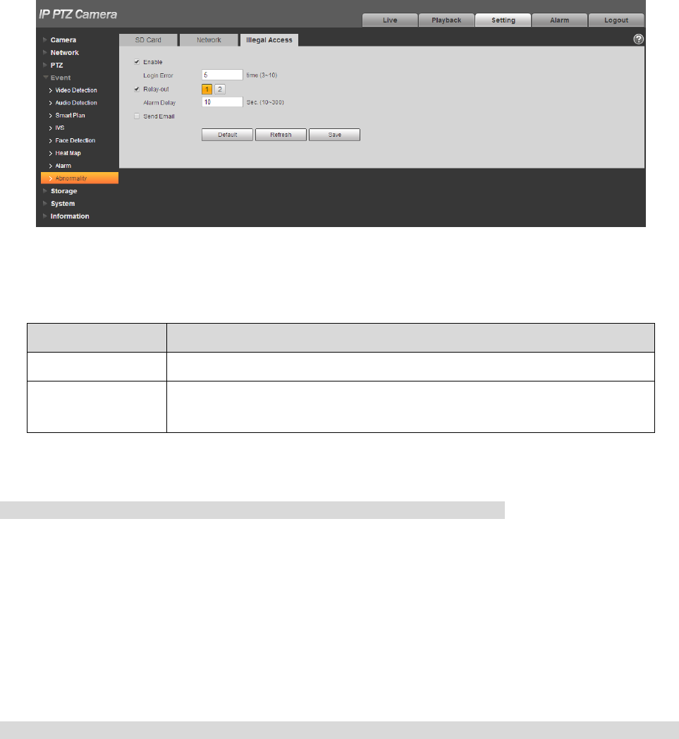
4.4.8.3 Illegal Access
When the login password error reaches a certain number of times, it will generate illegal access alarm.
Step 1
Select “Setup > Event > Abnormity > Illegal Access”.
The system will display the interface of “Illegal Access”, which is shown in Figure 4-98.
124
Figure 4-98
Step 2
Configure info of each parameter according to the actual needs; refer to Table 4-33 for more details.
Parameter
Note
Enable
Click it to enable illegal access alarm.
Login error
It will trigger alarm of illegal access after entering wrong password for
some certain times, and the account will be locked.
Table 4-33
Note
Please refer to “4.4.1.1 Motion Detection” for description of other parameters.
Step 3
Click “Save” to complete config.
4.5 Storage Management
Here you can set schedule, storage mode and record control.
4.5.1 Schedule
Before schedule setup, user must set record mode in record control as auto status.
Note
If record mode in record control is off, then device will not record or snapshot according to the schedule.
4.5.1.1 Record
Step 1
Select “Setup > Storage > Schedule > Record Schedule”.
The system will display the interface of “Record Schedule”, which is shown in Figure 4-99.
125
Figure 4-99
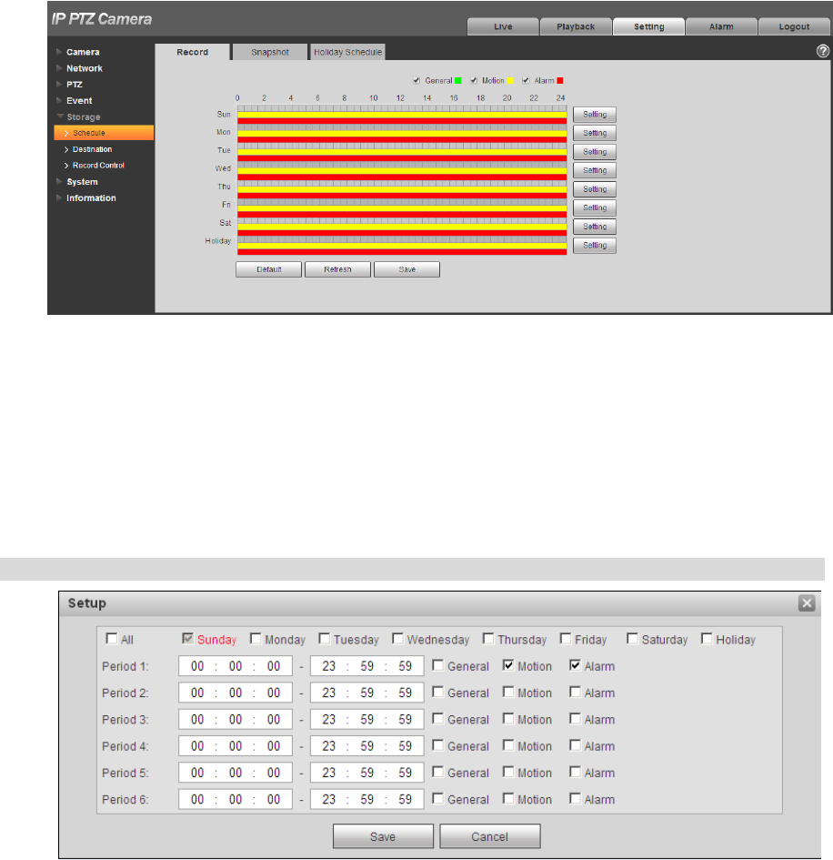
Step 2
From Monday to Sunday select record time, click “Setup” on the right. See Figure 4-100 for more details.
Set period according to actual needs. There are six periods available each day.
By checking or cancel, you can add or delete three types of record schedule: General, Motion, and
Alarm.
Note
Period setup can be done by dragging in record schedule interface while not releasing left mouse.
Figure 4-100
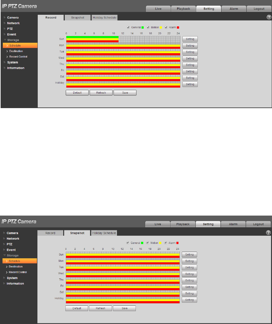
Step 3
Click “Save”, return to record schedule interface. See Figure 4-101.
Green color stands for the general record.
Yellow color stands for the motion detect record.
Red color stands for the alarm record.
126
Figure 4-101
Step 4
Click “Save” on the “Record Schedule” interface, the system prompts “Successfully Saved”, and the
record schedule is completed.
4.5.1.2 Snapshot
Step 1
Select “Setup > Storage > Schedule > Snapshot Schedule”.
The system will display the interface of “Snapshot Schedule”, which is shown in Figure 4-102.
Figure 4-102
Step 2
Set the snapshot period according to step 2 and 3 of “4.5.1.1 Record”.
Step 3
127
Click “Save” and the system will prompt “Successfully Saved‟, then snapshot schedule is completed.
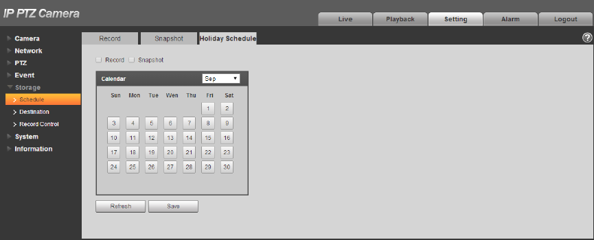
4.5.1.3 Holiday Schedule
Holiday schedule can set specific date as holiday.
Step 1
Select “Setup > Storage > Schedule > Holiday Schedule”.
The system will display the interface of “Holiday Schedule”, which is shown in Figure 4-103.
Figure 4-103
Step 2
Select date to set as holiday. The selected date will be highlighted in yellow.
Step 3
Check “Record/Snapshot”, click “Save”. System prompts it is successfully saved.
Step 4
Check “Record Schedule/Snapshot Schedule” interface, click setup next to “Holiday”, and refer to setup
of “Monday to Sunday”.
Step 5
Complete setup of “Holiday”, then it records/snapshots according to date set in holiday schedule.
4.5.2 Destination
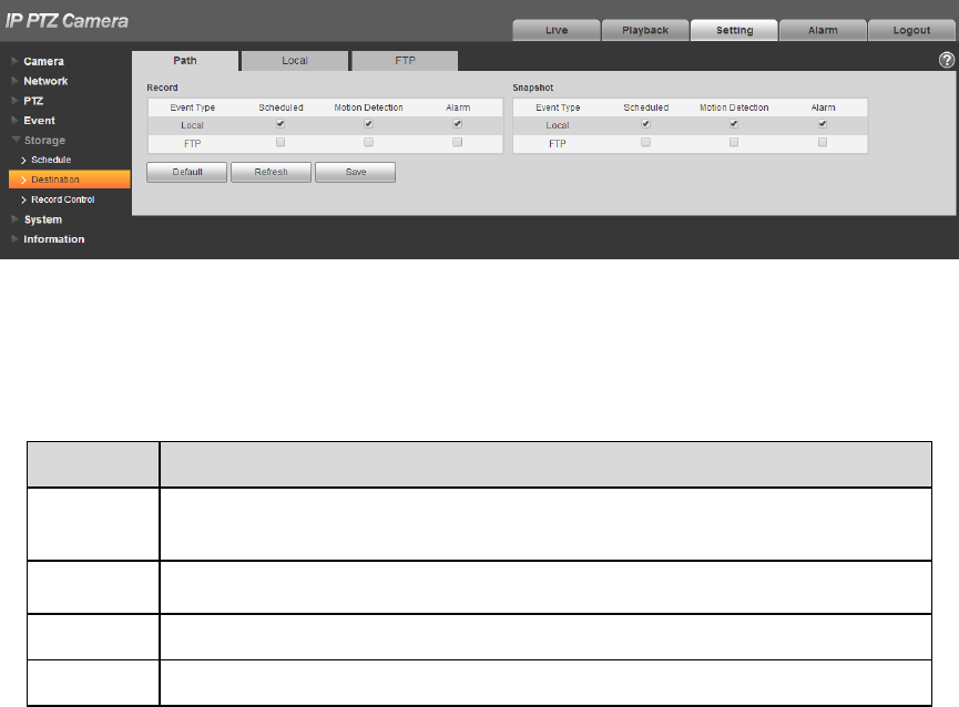
4.5.2.1 Path
Path can configure storage path of device record and snapshot. There are three options: Local, FTP
and NAS. You can only select one mode. System can save according to the event types. It is
corresponding to the three modes (general/motion/alarm) in the schedule interface. Please check the
box to enable the save functions.
Note: Only some devices support NAS storage, please refer to the actual device.
Step 1
128
Select “Setup > Storage > Destination > Path”.
The system will display the interface of “Path”, which is shown in Figure 4-104.
Figure 4-104
Step 2
Configure info of each parameter according to the actual needs; please refer to Table 4-34 for more
details.
Parameter
Function
Event
Type
It includes: scheduled, motion detect and alarm.
Local
It is saved in the SD card.
FTP
It is saved in the FTP server.
NAS
It is saved in NAS server.
Table 4-34
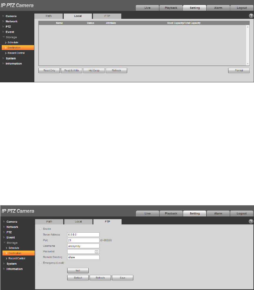
4.5.2.2 Local
Here it can display kinds of information of local SD card in the local storage list. You can also realize
several operations such as read-only, read & write, hot swap and format.
Select “Setup > Storage > Destination > Local”, the system will display the interface of “Local” shown in
Figure 4-105.
129
Figure 4-105
Click “Read only” to set the SD card as read only.
Click “Read & Write” to set the SD card as read & write.
Click “Hot Swap” to realize hot swap upon the SD card.
Click “Format” to realize formatting upon the SD card.
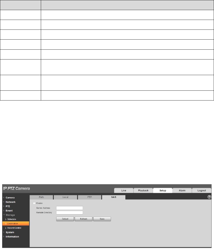
4.5.2.3 FTP
You need to check the box to enable the FTP function. When network disconnect occurred or there is
malfunction, emergency storage can save the record/snapshot to the local SD card.
Step 1
Select “Setup > Storage > Destination > FTP”, the system will display the interface of “FTP” shown in
Figure 4-106.
Figure 4-106
Step 2
Configure info of each parameter according to the actual needs; please refer to Table 4-35 for more
details.
130
Parameter
Note
Enable FTP
Click it to enable FTP function
Server Address
FTP server address
Port
FTP server port
User name
User name used to log in FTP server.
Password
Password used to log in FTP server.
Remote
Directory
Store it to the directory of FTP server.
Emergency
(Local)
Click it and it will store to local SD card when FTP storage abnormity
occurs.
Test
Click the button to test if FTP server can be connected.
Table 4-35
Step 3
Click “Save” to complete config.
4.5.2.4 NAS
When it selects NAS storage mode, NAS function can be enabled. You can store file to NAS server
when selecting NAS storage.
Step 1
Select “Setup > Storage > Destination > NAS”, the system will display the interface of “NAS” shown in
Figure 4-107.
Figure 4-107
Step 2
Configure info of each parameter according to the actual needs; please refer to Table 4-36 for more
details.
131
Parameter
Note
Enable NAS
Click it to enable NAS function.
Server Address
NAS server address.
Remote
Directory
Store it to the directory of the NAS server.
Table 4-36
Step 3
Click “Save” to complete config.
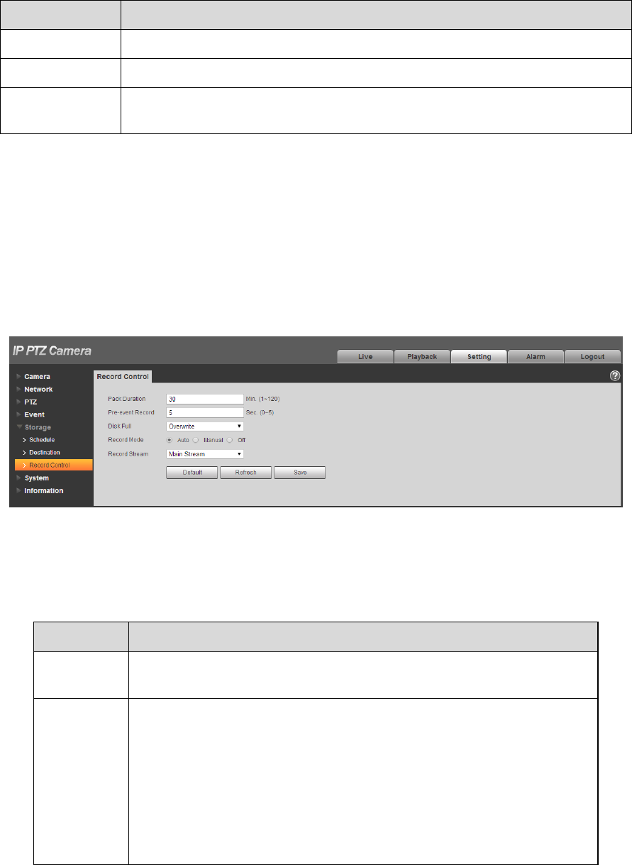
4.5.3 Record control
Step 1
Select “Setup > Storage > Record Control”, the system will display the interface of “record Control”
shown in Figure 4-108.
Figure 4-108
Step 2
Configure info of each parameter according to the actual needs; please refer to the following sheet for
more details.
Parameter
Function
Pack
Duration
It is to set the pack duration of each record file; it is 30 mins by
default.
Pre-event
Record
It is to set pre-event record time.
For example, when it inputs 5, then the system will read the record
video of first 5 seconds of the internal storage and record it into the
file.
Note
Configure pre-event record time, when alarm record or motion
detection record occurs, if there is no record, system will record the
preceding n seconds video data into the record file.
132
Disk Full
There are two options: stop recording or overwrite the previous files
when HDD is full.
Stop: Current working HDD is overwriting or current HDD is full,
it will stop record.
Overwrite: Current working HDD is full; it will overwrite the
previous file.
Record
mode
There are three modes: Auto/manual/close. It starts recording when
selecting manual mode, it records within the range of schedule when
selecting auto mode.
Record
stream
There are two options: main stream and sub stream.
Table 4-37
Step 3
Click “Save” to complete config.
4.6 System
4.6.1 General
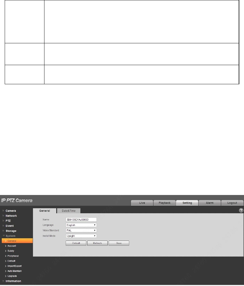
4.6.1.1 General
Step 1
Select “Setup > System > General”, the system will display the interface of “General” shown in Figure
4-109.
Figure 4-109
Step 2
Configure info of each parameter according to the actual needs; please refer to Table 4-38 for more
details.
133
Parameter
Function
Device
Name
It is to set device name.
Note
Different devices may have different names.
Language
You can select the language from the dropdown list.
Video
Standard
It is to display the video format of device, such as 50Hz.
TV Output
It can select on or off, the device which only supports TV output can
have this function.
Note
It will disable the intelligent functions when it is confirmed to enable
TV output.
It will disable TV output when it is confirmed to enable intelligent
functions.
Some models support SDI, HDCVI functions.
Install
Mode
It is to set the installation mode of the device, you can select upright
or inverted.
Table 4-38
Step 3
Click “Save” to complete config.
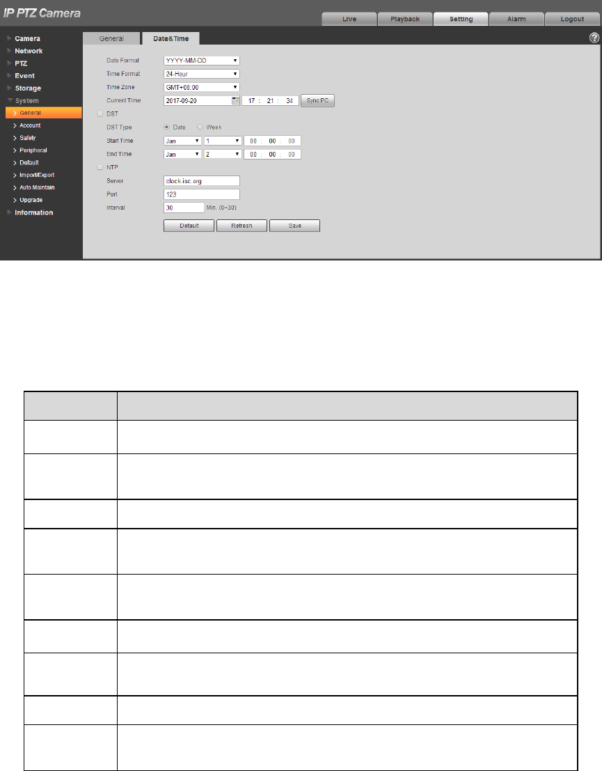
4.6.1.2 Date & Time
Step 1
Select “Setup > System > General > Date & Time”, the system will display the interface of “Date & Time”
shown in Figure 4-110.
134
Figure 4-110
Step 2
Configure info of each parameter according to the actual needs; please refer to Table 4-39 for more
details.
Parameter
Function
Date format
Here you can select date format from the dropdown list.
Time
Format
Here you can select the corresponding time format which needs to
be displayed.
Time zone
The time zone of the device.
System
time
It is to set system time. It becomes valid after you set.
DST
Here you can set begin time and end time of DST. You can set
according to the date format or according to the week format.
NTP
You can check the box to enable network time sync function
NTP server
You can set the address of time serve.
Port
It is to set the port of time server.
Update
period
It is to set the sync interval between the device and the time server.
Table 4-39
Step 3
135
Click “Save” to complete config.
4.6.2 Account
4.6.2.1 Account
Only when users have the right of account management then can it realize account management
operation.
For the character in the following user name or the user group name, system max supports 15-
digits. The valid string includes: character, number, and underline.
Password can be 0~32 characters in number and letter only. User can modify other user‟s
password.
The user amount is 18 and the group amount is 8 when the device is shipped out of the factory.
User management adopts group/user modes. The user name and the group name shall be unique.
One user shall be included in only one group.
Currently logged in user cannot change his/her own right.
There is one default user admin during initialization. Admin belongs to high right user by default
when it is out of factory.
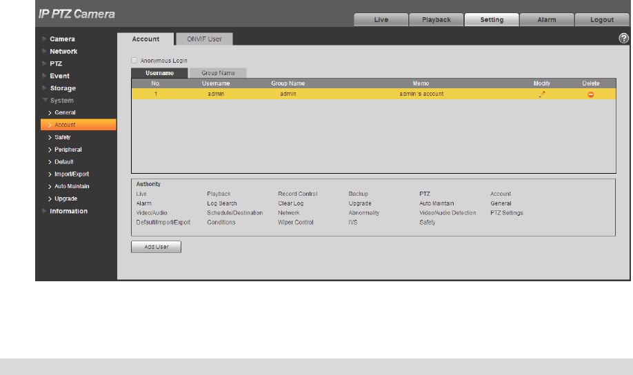
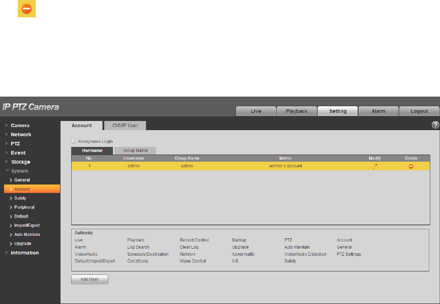
4.6.2.1.1 User Name
You can enable anonymity login, add/remove user and modify user name and etc. in “Setup > System >
Account > Account > User name. See Figure 4-111.
Figure 4-111
Note
The version info and other icons in the live interface except alarm have no right control temporarily.
136
Anonymous login: Enable “Anonymity Login”, and input IP. No username or password is required, you
can log in by anonymity (with limited rights). You can click logout to use other users to log in the device.
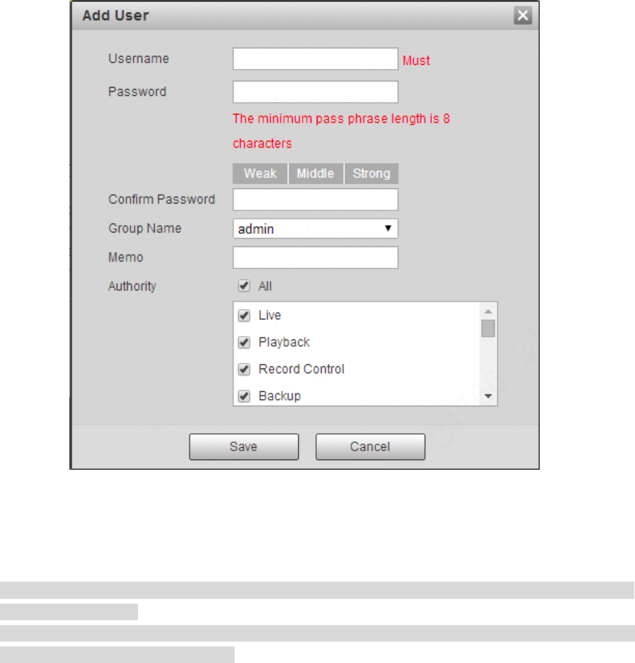
Add user
It is to add user in group and set the right control of the user.
The highest right user admin can‟t be deleted by default.
Step 1
Click “Add User” and the system will pop out the interface of “Add User”, which is shown in Figure 4-112.
Figure 4-112
Step 2
Enter user name and password, select group and check authority list.
Note
Once the group is selected, then the user right can only be subset of the group which can‟t surpass
the right of the group.
Users are recommended to make it lower than senior users when defining general users in order to
make user management convenient.
137
Step 3
Click “Save”.
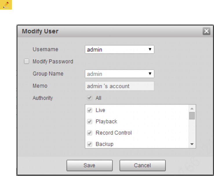
Modify user
Step 1
Click the icon which is corresponding to the users which needs to be modified.
The system will pop out the interface of “Modify User” which is shown in Figure 4-113.
Figure 4-113
Step 2
Modify the user information according to actual needs.
Step 3
Click “Save”.
Modify password
Step 1
Select the check box of “Modify Password”.
Step 2
Input old password, input new password and confirm it.
Step 3
Click “Save”.
138
Delete User
Click the icon of corresponding user which needs to be deleted, and then you can delete the user.
4.6.2.1.2 Group
You can realize add group, delete group, modify password and other operations in “Setup > System >
Account > Group”. You can refer to Figure 4-114 for more details.
Figure 4-114
Add Group:
Please refer to “4.6.2.1.1 Username” for more details.
Modify Group
Please refer to “4.6.2.1.1 Username” for more details.
Delete Group
Please refer to “4.6.2.1.1 Username” for more details.
4.6.2.2 ONVIF User
Users can add Onvif user on the WEB interface, it can also modify the users which have existed.
Step 1
Select “Setup > System > Account > ONVIF User” and the system will display the interface of “ONVIF
User”, which is shown in Figure 4-115.
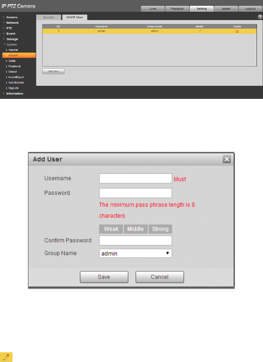
140
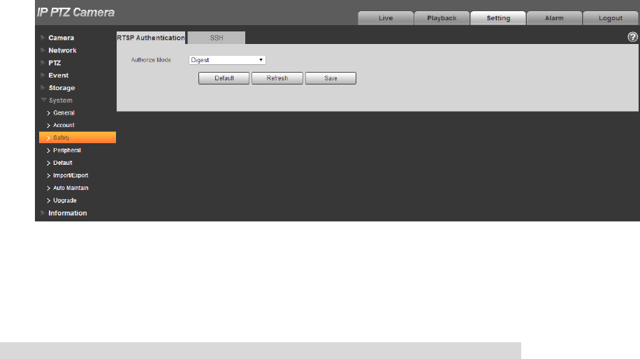
4.6.3 Safety
4.6.3.1 RSTP Authentication
It can set the authorize mode of media stream.
Step 1
Select “Setup > System > Safety > RSTP Authentication” and the system will display the interface of
“RSTP Authentication”, which is shown in Figure 4-117.
Figure 4-117
Step 2
Select authorize mode. It can select Digest, Basic or None. It is Digest by default.
Note
Click “Default” and the authorize mode will be selected as “Digest” automatically.
4.6.3.2 SSH
It can select to enable SSH service to acquire higher safety.
Step 1
Select “Setup > System > Safety > SSH” and the system will pop out the interface of “SSH”, which is
shown in Figure 4-118.
141
Figure 4-118
Step 2
Select “SSH Enable” to enable SSH service.
Note
Click “Default” to cancel SSH service.
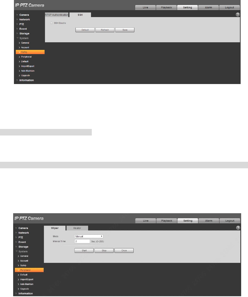
4.6.4 Peripheral
Note
Only some models support peripheral management, please refer to the actual device for more details.
4.6.4.1 Wiper
You can make settings for wiper.
Step 1
Select “Setup > System > Peripheral > Wiper”.
The system will display the interface of “Wiper” which is shown in Figure 4-119 and Figure 4-121.
Figure 4-119
142
Figure 4-120
Figure 4-121
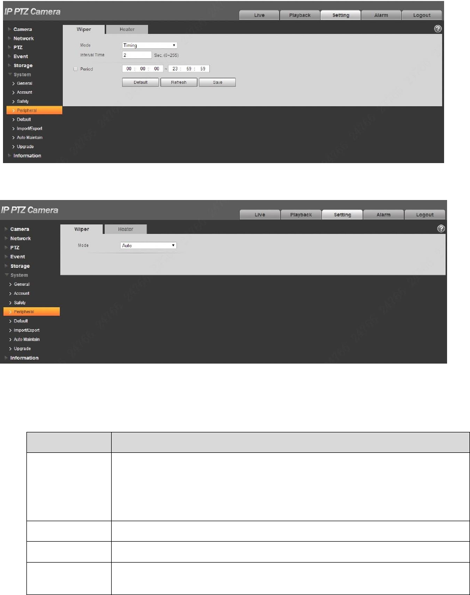
Step 2
Configure info of each parameter according to the actual needs. Refer to Table 4-40 for more details.
Parameter
Note
Mode
It is to set wiper mode, you can select timing and manual, it is timing by
default.
In timing mode, it needs to set the period of enabling wiper.
In manual mode, it needs to enable wiper by manual operation.
In auto mode, it is to enable wiper automatically.
Interval Time
It is the interval from when the wiper stops to when the wiper is enabled.
Period
Click it to set the period when the wiper is enabled in timing mode.
Start, Stop,
Once
In manual mode:
Click “Start”, and the wiper operates regularly according to the interval
143
which has been set.
Click “Stop”, and the wiper stops.
Click “Once” and the wiper operates once.
Table 4-40
Step 3
Click “Save” to complete config.
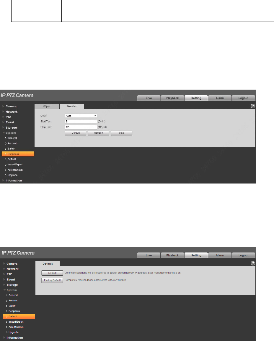
4.6.4.2 Heater
Go to “Setup > System > Peripheral >Heater” and the config interface is shown in Figure 4-122.
Figure 4-122
4.6.5 Default
Note
Go to “Setup > System > Default” and click “Default” to restore some device settings back to default.
The config interface is shown in Figure 4-123.
Figure 4-123
144
You can select default mode according to the actual needs.
Default: Config (except network IP address, user management info and so on) default.
Factory default: The function is equivalent to the reset button of the speed dome. It can help to
restore all the config info to factory default, the device IP address will be restored to default IP
address as well. After clicking “Factory Default”, it needs to input the password of admin user on
the interface. It can restore the device after the system judges that the password is correct.
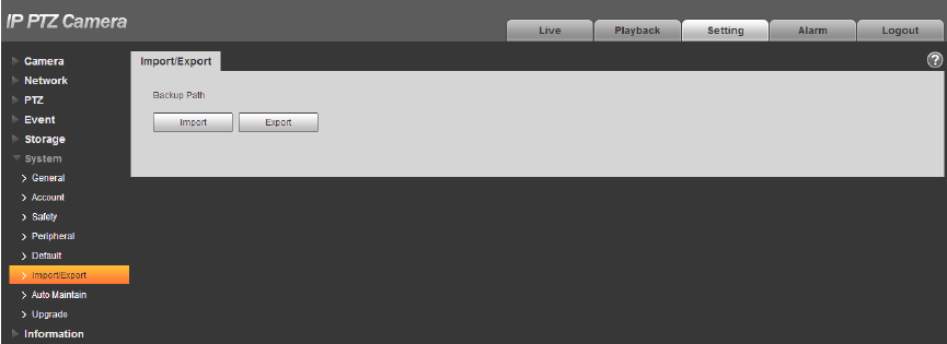
4.6.6 Import/Export
It can realize quick config of several devices via configuring file import and export when the config
method of several devices is the same.
Step 1
Select “Setup > System > Import Export” on the WEB end of some device.
The system will display the interface of “Import & Export”, which is shown in Figure 4-124.
Figure 4-124
Step 2
Click “Export” to export the config file (.backup file) to local.
Step 3
Click “Import” on the “Import & Export” interface of the WEB end of the device to be configured, and
import the file into the system. So far the device config is completed.
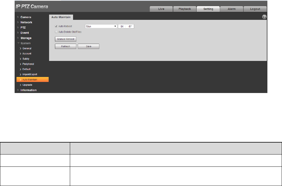
4.6.7 Auto Maintenance
Users can set auto reboot system or auto delete file, it needs to set period and time for auto reboot
system, it is 02:00 every Tuesday by default. It needs to set the period of the file if it needs to auto
delete old files, and delete the file within the specific period.
Step 1
145
Select “Setup > System > Auto Maintenance”.
The system will display the interface of “Auto Maintenance” in Figure 4-125.
Figure 4-125
Step 2
Configure the info of each parameter according to the actual needs; please refer to Table 4-41 for more
details.
Parameter
Function
Auto Reboot
Check it and set auto reboot time.
Auto Delete Old Files
Check it and you can customize period, the range of period is from 1 to 31
days.
Table 4-41
Step 3
Click “Save” to make config valid.
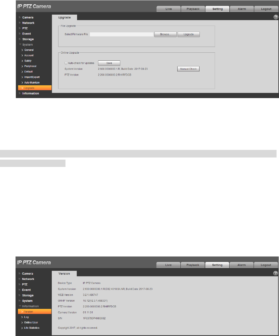
4.6.8 Upgrade
You can realize upgrade operation in “Setup > System > Upgrade”. See Figure 4-126 for more details.
146
Figure 4-126
Click “Browse” and select upgrade file, click “Upgrade” to realize firmware upgrade. The upgrade file is
“*.bin” file.
Note
It needs to reboot the device when upgrading wrong files; otherwise some module functions of the
device will be disabled.
4.7 Information
The system supports checking system version, online users, log and etc.
4.7.1 Version
Here you can view system hardware features, software version, release date and etc. Please note the
following information is for reference only.
Check the version info of the current WEB end in “Setup > System > Version”. See Figure 4-127 for
more details.
Figure 4-127
147
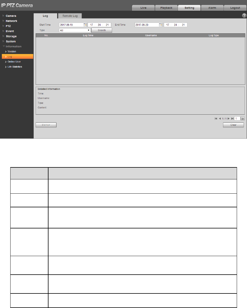
4.7.2 Log
In “Setup > System > Log‟, you can check the device operation info implemented by users and some
system info, see Figure 4-128 for more details.
Figure 4-128
Please refer to Table 4-42 for log parameter information.
Parameter
Function
Start time
Set the start time of the requested log. (The earliest time is 2000/1/1)
End time
Set the end time of the requested log. (The latest time is 2037/12/31)
Type
Log type consists of system operation, config operation, data
management, alarm event, record operation, user management and
log clear.
Search
First it needs to set start time and end time of the log to be searched,
and select log type, click “Search”, it will display search bars
dynamically; click “Stop” to pause log search, and it will display the
searched bars and period area.
Log
information
Click log record and it will display the detailed info of the log.
Clear
It is to clear all the log info on the device, but it fails to support
classified clearance of log info.
Backup
You can click this button to backup system log files which is
searched to current PC.
148
Table 4-42
Specific meaning included by different log types:
System operation: It includes application program enable, abnormal logout, logout, application
program reboot, close/reboot device, system reboot, and system upgrade.
Config operation: It includes save config, delete config file.
Data operation; It includes setting hardware type, clearing data, hot swap, FTP status, record mode.
Event operation (it is to record the events such as video detection, IVS, alarm, abnormity and etc.):
It includes event start and event end.
Record operation: It includes file access, file access error, and file inquiry.
User management (it is to record the user management modification and user login and logout): It
includes login, logout, add user, delete user, modify user, add group, delete group, modify group.
Clear log: It is to clear log.
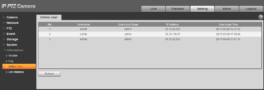
4.7.3 Online User
You can check the user info on the current WEB in “Setup > System > Online User”, see Figure 4-129
for more details.
Figure 4-129
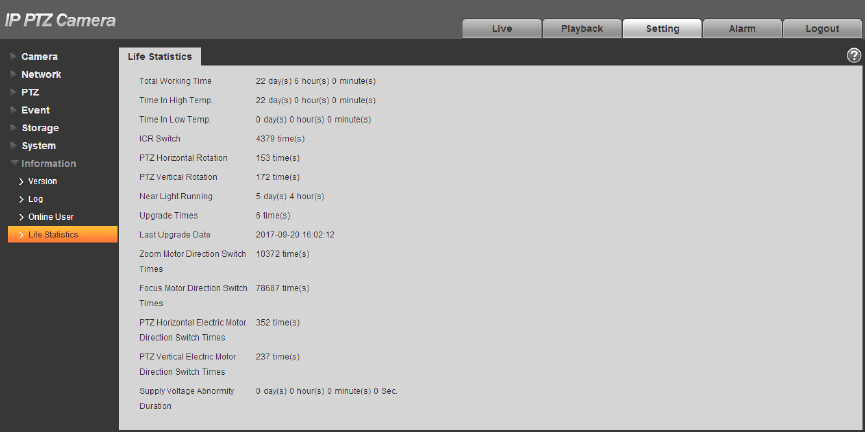
4.7.4 Life Statistics
Go to “Setup > Information > Life Statistics” and check running status of the device. The interface is
shown in Figure 4-130.
149
Figure 4-130
150
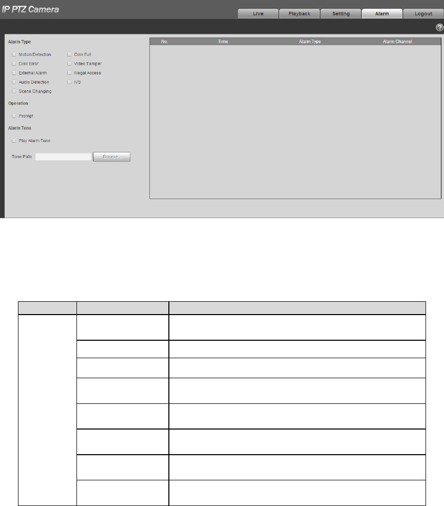
5 Alarm
The alarm module mainly provides users with alarm events to subscribe; it will record the alarm info in
the right column when it triggers the alarm event which has been subscribed by users.
Step 1
Click “Alarm” and the system will display the interface of “Alarm”, which is shown in Figure 5-1.
Figure 5-1
Step 2
Configure info of each parameter according to the actual needs; please refer to Table 5-1 for more
details.
Type
Parameter
Function
Alarm
type
Motion detection
System records alarm when motion detection
alarm occurs,
Disk full
System records alarm when disk is full.
Disk error
System records an alarm when HDD malfunctions.
Video tamper
System records alarm when camera is viciously
masked.
External alarm
System records alarm when alarm inputs the
device.
Illegal access
System records alarm when there is unauthorized
access.
Audio detection
System records alarm when audio detection
occurs.
IVS
System records alarm when intelligent config
occurs
151
Type
Parameter
Function
Scene changing
System records alarm when scene changing is
triggered.
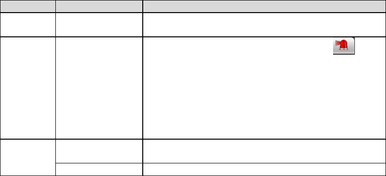
Operation
Prompt
When alarm is triggered, there will be an in
main menu of alarm interface and system
automatically records alarm info. The icon
disappears when user click alarm menu bar.
Note:
If alarm interface is displayed, when alarm is
triggered, there will be no image prompt, but alarm
record will be in list on the right.
Alarm
Tone
Play Alarm Tone
When alarm occurs, system auto generates alarm
audio. The audio supports customized setup.
Tone Path
Here you can specify alarm sound file.
Table 5-1
152
6 Log out
Click log out button, system goes back to log in interface. See Figure 6-1.
Figure 6-1
Note
This manual is for reference only. Slight difference may be found in user interface.
All the designs and software here are subject to change without prior written notice.
All trademarks and registered trademarks mentioned are the properties of their respective
owners.
If there is any uncertainty or controversy, please refer to the final explanation of us.
Please visit our website for more information.
FCC Statement
1. This device complies with Part 15 of the FCC Rules. Operation is subject to the following two conditions:
(1) this device may not cause harmful interference, and (2) this device must accept any interference received,
including interference that may cause undesired operation.
2. The users manual or instruction manual for an intentional or unintentional radiator shall caution the user
that changes or modifications not expressly approved by the party responsible for compliance could void the user's
authority to operate the equipment. In cases where the manual is provided only in a form other than paper, such
as on a computer disk or over the Internet, the information required by this section may be included in the manual
in that alternative form, provided the user can reasonably be expected to have the capability to access information
in that form.
3. (b) For a Class B digital device or peripheral, the instructions furnished the user shall include the following
or similar statement, placed in a prominent location in the text of the manual:
NOTE: This equipment has been tested and found to comply with the limits for a Class B digital device, pursuant to
Part 15 of the FCC Rules. These limits are designed to provide reasonable protection against harmful interference
in a residential installation. This equipment generates, uses and can radiate radio frequency energy and, if not
installed and used in accordance with the instructions, may cause harmful interference to radio communications.
However, there is no guarantee that interference will not occur in a particular installation. If this equipment does
cause harmful interference to radio or television reception, which can be determined by turning the equipment off
and on, the user is encouraged to try to correct the interference by one or more of the following measures:
-- Reorient or relocate the receiving antenna.
-- Increase the separation between the equipment and receiver.
-- Connect the equipment into an outlet on a circuit different from that to which the receiver is connected.
-- Consult the dealer or an experienced radio/TV technician for help.
4. RF exposure warning
This equipment must be installed and operated in accordance with provided instructions and the antenna(s) used
for this transmitter must be installed to provide a separation distance of at least 20 cm from all persons and must
not be co-located or operating in conjunction with any other antenna or transmitter. End-users and installers must
be provide with antenna installation instructions and transmitter operating conditions for satisfying RF exposure
compliance.