Zhejiang Dahua Vision Technology DHNVR21W Network Video Recorder User Manual 3
Zhejiang Dahua Vision Technology Co., Ltd Network Video Recorder 3
Contents
- 1. User Manual -1
- 2. User Manual -2
- 3. User Manual -3
- 4. User Manual -4
User Manual -3
206
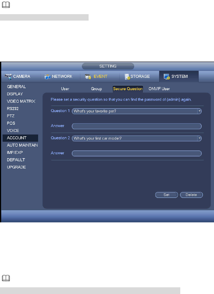
4.10.1.3 Security Question
Note
This function is for admin user only.
Here you can change security questions. After you successfully answered security questions, you can
reset admin account password.
From main menu->Setting->System->Account->Security question, the interface is shown as below. See
Figure 4-212. Input correct security answers and then click Delete button at the bottom of the interface,
you can reset security questions and answers.
Figure 4-212
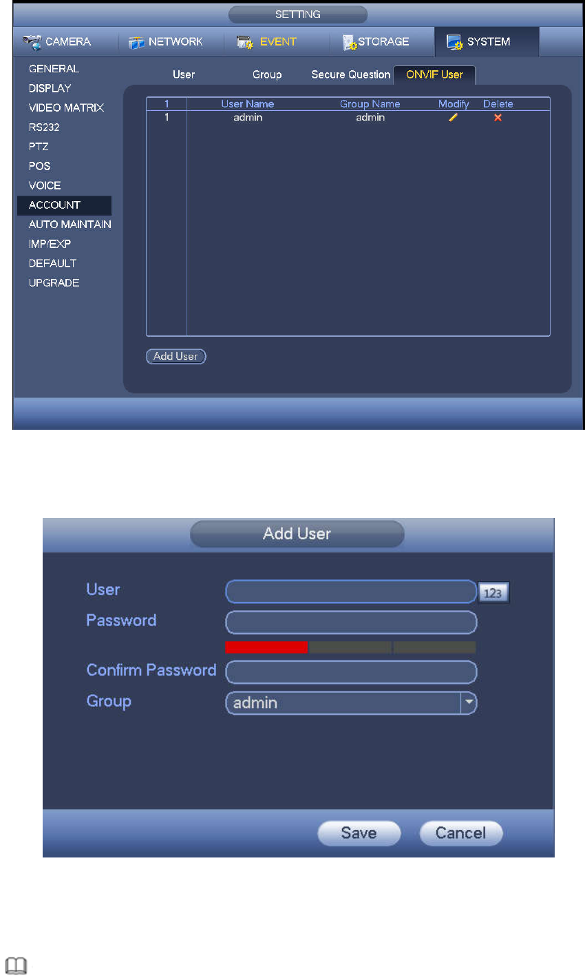
4.10.1.4 ONVIF User
When the camera from the third party is connected with the NVR via the ONVIF user, please use the
verified ONVIF account to connect to the NVR. Here you can add/delete/modify user
Note
The default ONVIF user is admin. It is created after you initialize the NVR.
Step 1 From main menu->Setting->System->Account->ONVIF User.
Enter ONVIF interface. See Figure 4-213.
207
Figure 4-213
Step 2 Click Add User button.
Enter Add User interface. See the following figure.
Figure 4-214
Step 3 Set user name, password and then select group from the dropdown list.
Step 4 Click Save to complete setup.
Note
208
Click to change user information, click to delete current user.
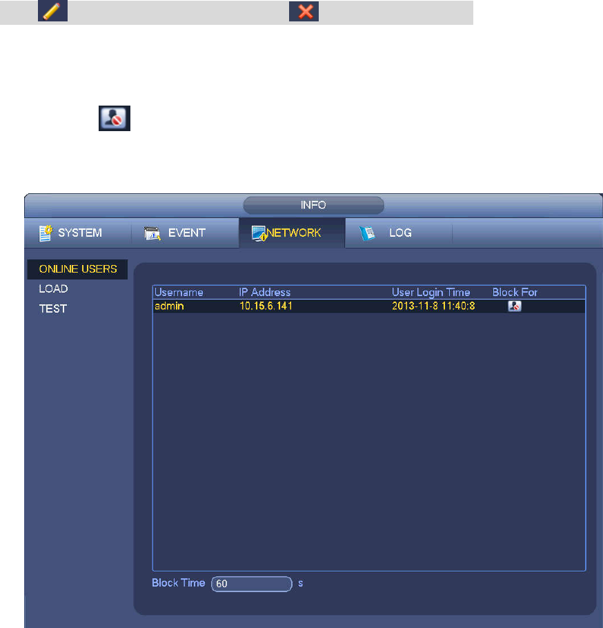
4.10.1.5 Online User
Here is for you manage online users connected to your NVR. See Figure 4-215.
You can click button to disconnect or block one user if you have proper system right.
System detects there is any newly added or deleted user in each five seconds and refresh the list
automatically.
Figure 4-215
4.10.2 System Info
4.10.2.1 Version
From main menu->Info->System->version, you can go to version interface.
It is to view NVR version information. Slight different may be found on the user interface.
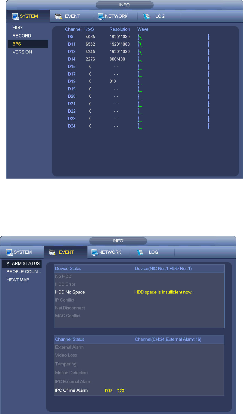
4.10.2.2 BPS
Here is for you to view current video bit rate (kb/s) and resolution. See Figure 4-216.
209
Figure 4-216
4.10.2.3 Event Information
4.10.2.3.1 Alarm Status
From main menu->info-Event, here you can view the channel status of the remote device, connection log
and etc. See Figure 4-217.
Figure 4-217
210
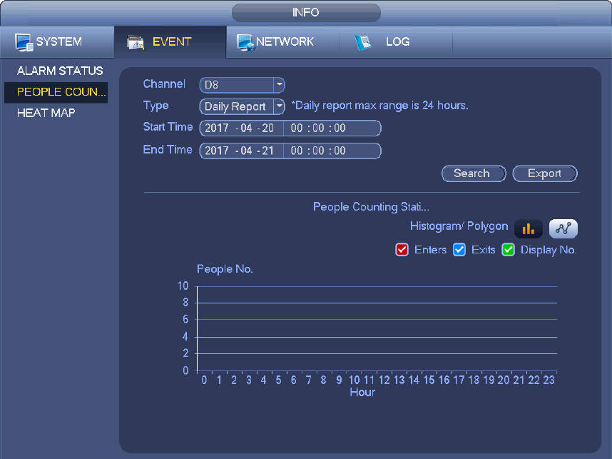
4.10.2.3.2 People Counting
This function allows system to detect the people flow amount in the specified zone and display the people
amount statistics image.
From main menu->Info->Event->People Counting, you can go to the following interface. See
Figure 4-218.
Channel: Please select a channel from the dropdown list.
Type: Please select report type from the dropdown list. It includes daily report/monthly report/annual
report. You can click to select histogram or polygon chart.
Start time/end time: Input start time and end time of the people counting.
Enter: Check to search enter amount.
Exit: Check the box to search exit amount.
Display No.: Check the box, system can display enter and exit people amount in the report.
Figure 4-218
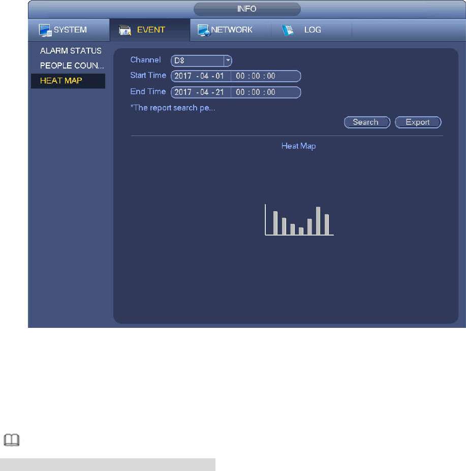
4.10.2.3.3 Heat Map
It is to search and view the heat map of each channel.
From main menu->Info->Event->Heat Map, you can go to the following interface. See Figure 4-219.
Select a channel, input start time and end time. Please note the report search period shall be within one
month.
Click Search button, you can view the heat map report.
211
Figure 4-219
4.10.3 Voice
The audio function is to manage audio files and set schedule play function. It is to realize audio broadcast
activation function.
Note
This function is for some series product only.
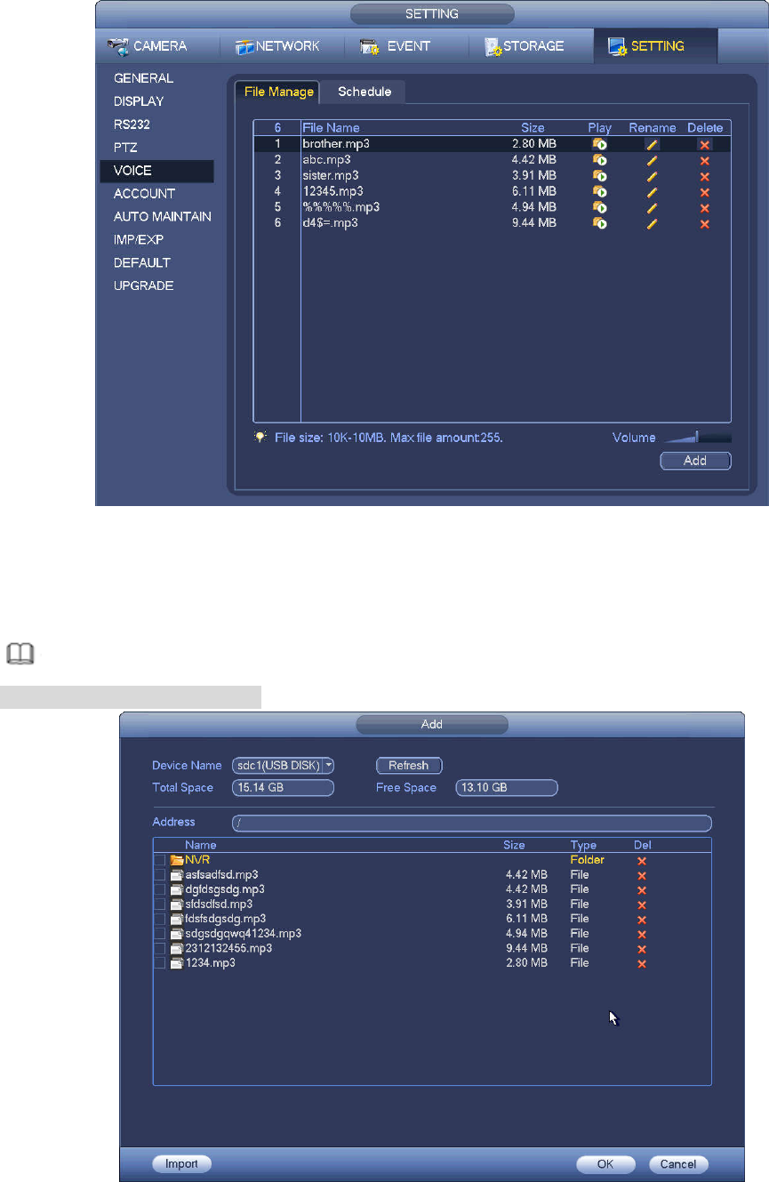
4.10.3.1 File Manage
Here you can add audio file, listen to the audio file, or rename/delete audio file. Here you can also set
audio volume. See Figure 4-220.
212
Figure 4-220
Click Add button, you can add audio file and import the audio file via the USB device. The audio file
format shall be MP3 or PCM. See Figure 4-221.
Note
The file size shall be 2K-10MB.
Figure 4-221
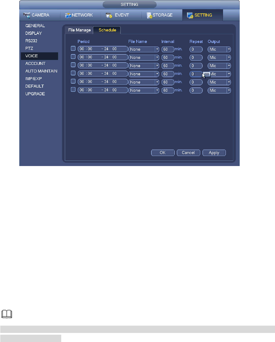
4.10.3.2 Schedule
213
It is to set schedule broadcast function. You can play the different audio files in the specified periods. See
Figure 4-222.
Figure 4-222
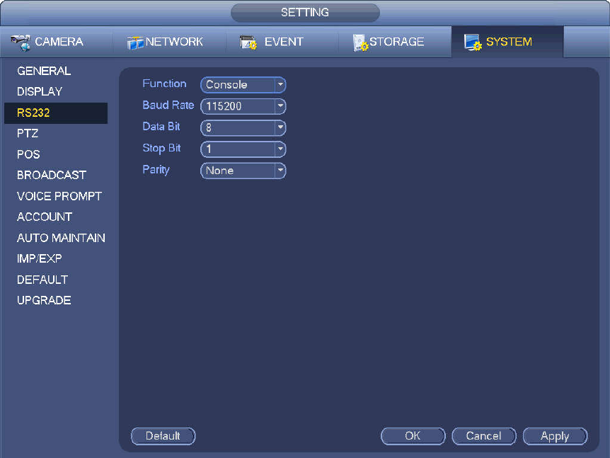
4.10.4 RS232
After setting RS232 parameters, the NVR can use the COM port to connect to other device to debug and
operate.
From Main menu->Setting->System->RS232, RS232 interface is shown as below. There are five items.
See Figure 4-223.
Function: There are various devices for you to select.
Console is for you to use the COM or mini-end software to upgrade or debug the program.
Control keyboard is for you to control the device via the special keyboard.
Transparent COM (adapter) is to connect to the PC to transfer data directly.
Protocol COM is for card overlay function.
Network keyboard is for you to use the special keyboard to control the device.
PTZ matrix is to connect to the peripheral matrix control.
Note
Different series products support different RS232 functions. Please refer to the actual product for
detailed information.
Baud rate: You can select proper baud rate.
Data bit: You can select proper data bit. The value ranges from 5 to 8.
Stop bit: There are three values: 1/1.5/2.
Parity: there are five choices: none/odd/even/space mark.
System default setup is:
Function: Console
214
Baud rate:115200
Data bit:8
Stop bit:1
Parity: None
After completing all the setups please click save button, system goes back to the previous menu.
Figure 4-223
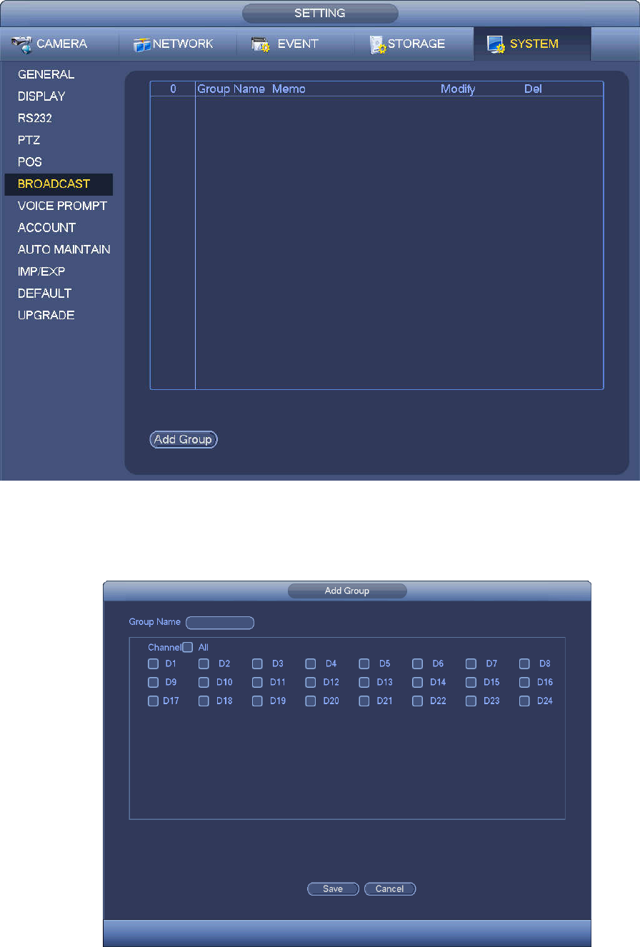
4.10.5 Broadcast
It is to broadcast to the camera, or broadcast to a channel group.
Step 1 From Mani menu->Setting->System->Broadcast.
Enter the following interface. See Figure 4-224.
215
Figure 4-224
Step 2 Click Add group.
Enter add group interface. See Figure 4-225.
Figure 4-225
Step 3 Input group name and select one or more channels.
216
Step 4 Click Save button to complete broadcast group setup.
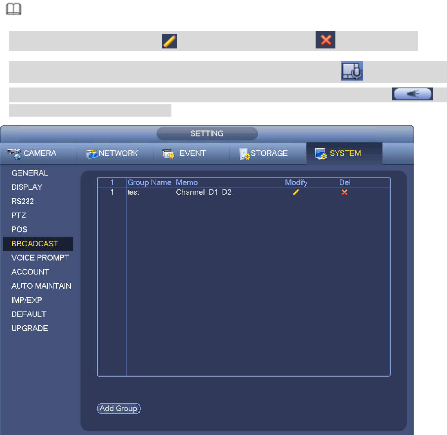
Note
On the broadcast interface, click to change group setup, click to delete group.
After complete broadcast setup, on the preview interface and then click on the navigation
bar, device pops up broadcast diaologue box. Select a group name and then click to
begin broadcast. See Figure 4-226.
Figure 4-226
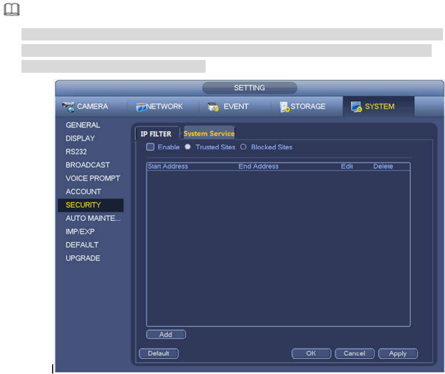
4.10.6 Security
4.10.6.1 IP Filter
IP filter interface is shown as in Figure 4-227. You can add IP in the following list. The list supports max 64
IP addresses. System supports valid address of IPv4 and IPv6. Please note system needs to check the
validity of all IPv6 addresses and implement optimization.
After you enabled trusted sites function, only the IP listed below can access current NVR.
If you enable blocked sites function, the following listed IP addresses cannot access current NVR.
Enable: Highlight the box here, you can check the trusted site function and blocked sites function.
You cannot see these two modes if the Enable button is grey.
Type: You can select trusted site and blacklist from the dropdown list. You can view the IP address
on the following column.
Start address/end address: Select one type from the dropdown list, you can input IP address in the
start address and end address. Now you can click Add IP address or Add IP section to add.
a) For the newly added IP address, it is in enable status by default. Remove the √ before the item,
217
and then current item is not in the list.
b) System max supports 64 items.
c) Address column supports IPv4 or IPv6 format. If it is IPv6 address, system can optimize it. For
example, system can optimize aa:0000: 00: 00aa: 00aa: 00aa: 00aa: 00aa as aa:: aa: aa: aa: aa:
aa: aa.
d) System automatically removes space if there is any space before or after the newly added IP
address.
e) System only checks start address if you add IP address. System check start address and end
address if you add IP section and the end address shall be larger than the start address.
f) System may check newly added IP address exists or not. System does not add if input IP
address does not exist.
Delete: Click it to remove specified item.
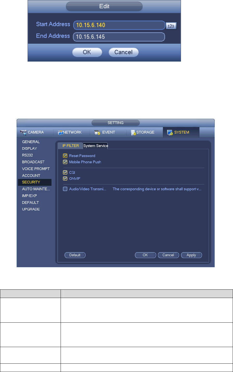
Edit: Click it to edit start address and end address. See Figure 4-228. System can check the IP
address validity after the edit operation and implement IPv6 optimization.
Default: Click it to restore default setup. In this case, the trusted sites and blocked sites are both null.
Note
If you enabled trusted sites, only the IP in the trusted sites list can access the device.
If you enabled blocked sites, the IP in the blocked sites cannot access the device.
System supports add MAC address.
Figure 4-227
218
Figure 4-228
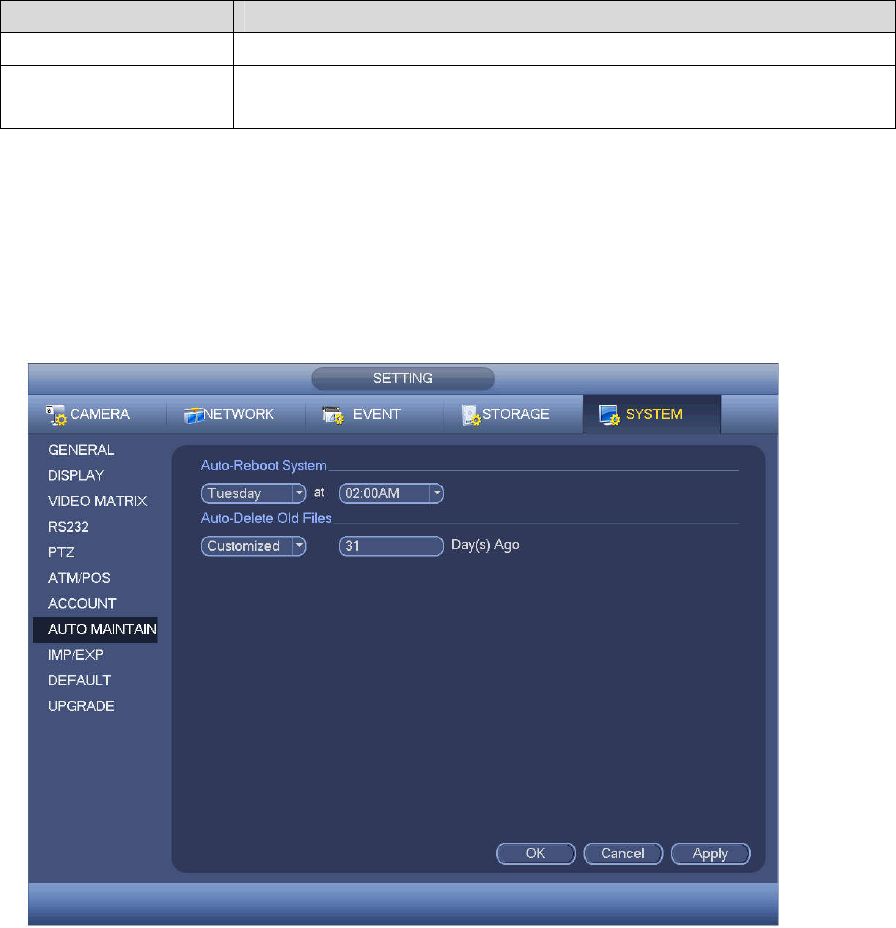
4.10.6.2 System Service
The device supports to enable and disable various system internal services.
Step 1 From main menu->System->Security ->System Service.
The System Service interface is displayed. See Figure 4-229.
Figure 4-229
Step 2 Configure the parameters. For details, see the below table.
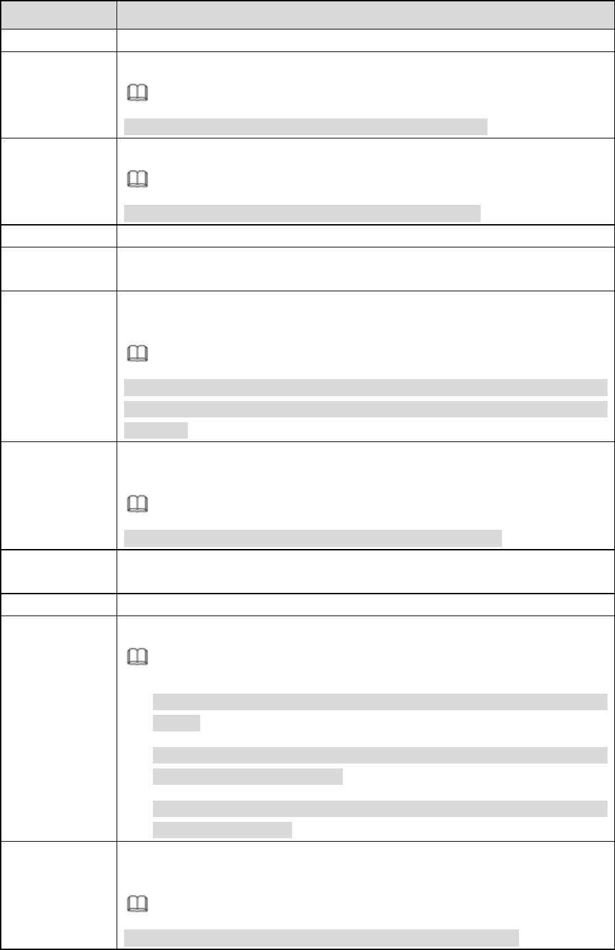
Parameter Description
Password Reset Enabled by default.
If it is disabled, the user can only use the security questions to reset
the password.
Mobile Phone Push Enabled by default.
The snapped pictures triggered at the device can be push to the
mobile app.
CGI Enabled by default.
The device can be connected via this protocol when enabled.
ONVIF Enabled by default.
219
Parameter Description
The device can be connected via this protocol when enabled.
Audio/VideoEncryption
The stream transmission is encrypted when this function is
enabled.The associated device or software shall support decryption.
Step 3 Click OK to complete the configuration.
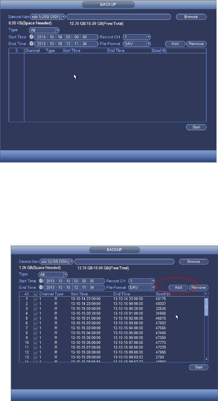
4.10.7 Auto Maintain
Here you can set auto-reboot time and auto-delete old files setup. You can set to delete the files for the
specified days. See Figure 4-230.
You can select proper setup from dropdown list.
After all the setups please click save button, system goes back to the previous menu.
Figure 4-230
4.10.8 Backup
4.10.8.1 File Backup
In this interface, you can backup record file to the USB device.
a) Connect USB burner, USB device or portable HDD and etc to the device.
b) From Main menu->Backup, you can go to the Backup interface. See Figure 4-231
220
Figure 4-231
c) Select backup device and then set channel, file start time and end time.
d) Click add button, system begins search. All matched files are listed below. System automatically
calculates the capacity needed and remained. See Figure 4-232.
e) System only backup files with a √ before channel name. You can use Fn or cancel button to
delete √ after file serial number.
f) Click backup button, you can backup selected files. There is a process bar for you reference.
g) When the system completes backup, you can see a dialogue box prompting successful backup.
Figure 4-232
221
h) Click backup button, system begins burning. At the same time, the backup button becomes stop
button. You can view the remaining time and process bar at the left bottom.
Note
During backup process, you can click ESC to exit current interface for other operation (For
some series product only). The system will not terminate backup process.
The file name format usually is: Channel number+Record type+Time. In the file name, the
YDM format is Y+M+D+H+M+S. File extension name is .dav.
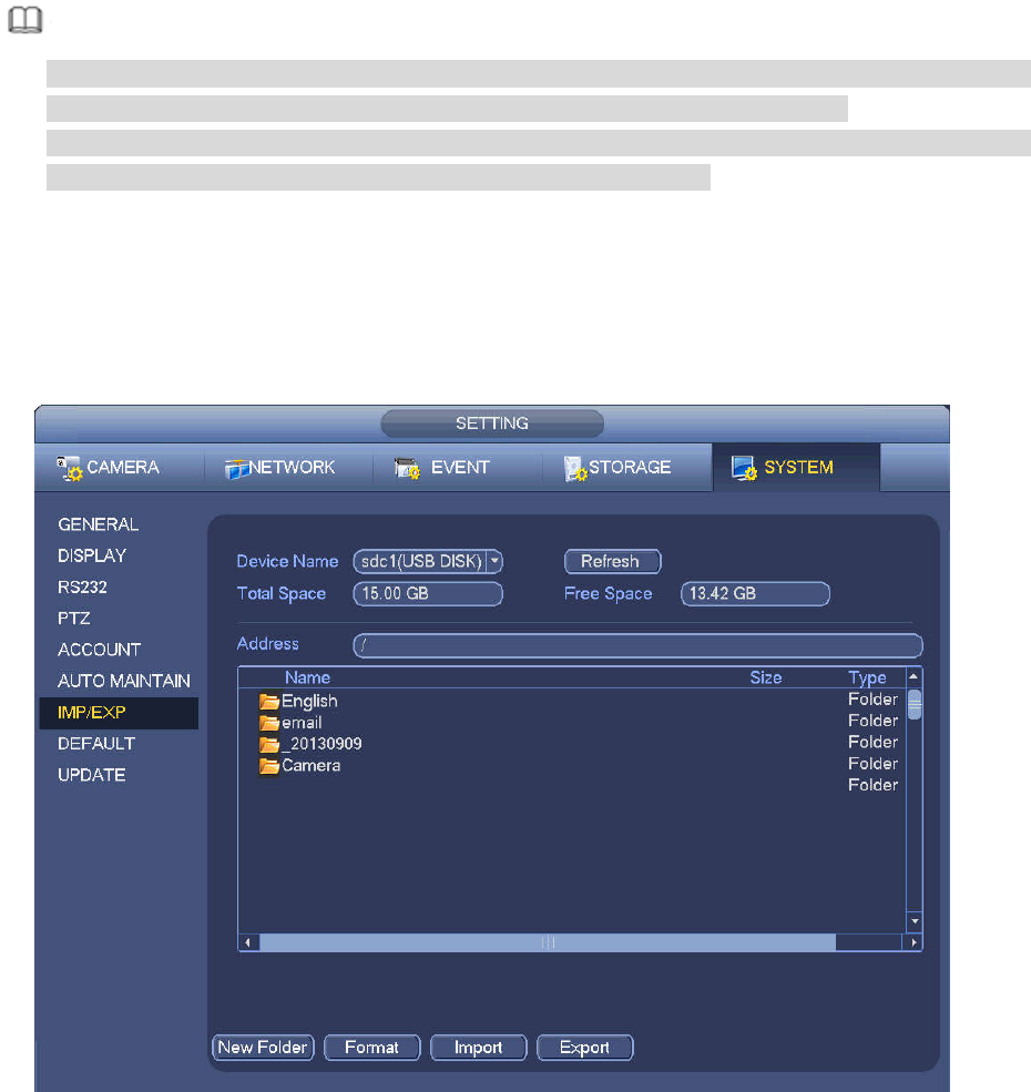
4.10.8.2 Import/Export
This function allows you to copy current system configuration to other devices. It also supports import,
create new folder, and delete folder and etc function.
From Main menu->Setting->System->Import/Export, you can see the configuration file backup interface is
shown as below. See Figure 4-233.
Figure 4-233
Export: Please connect the peripheral device first and then go to the following interface. Click
Export button, you can see there is a corresponding “Config_Time” folder. Double click the folder,
you can view some backup files.
Import: Here you can import the configuration files from the peripheral device to current device. You
need to select a folder first. You can see a dialogue box asking you to select a folder if you are
selecting a file. System pops up a dialogue box if there is no configuration file under current folder.
After successfully import, system needs to reboot to activate new setup.
Format: Click Format button, system pops up a dialogue box for you to confirm current operation.
System begins format process after you click the OK button.
222
Note
System cannot open config backup interface again if there is backup operation in the process.
System refreshes device when you go to the config backup every time and set current directory as
the root directory of the peripheral device.
If you go to the configuration backup interface first and then insert the peripheral device, please click
Refresh button to see the newly added device.
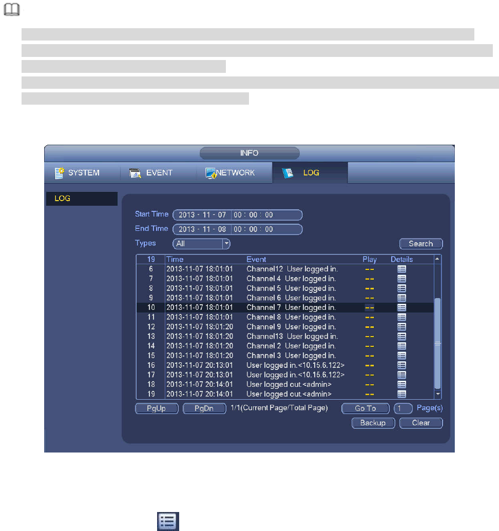
4.10.8.3 Backup Log
a) From Main menu->Info->Log, the interface is shown as below. See Figure 4-234.
Figure 4-234
b) Select log type and then set start time/end time, click Search button, you can see log time and
event information. Click to view detailed log information.
c) Select log items you want to save and then click backup button, you can select a folder to save
them. Click Start to backup and you can see the corresponding dialogue box after the process is
finish.
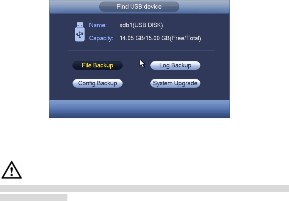
4.10.8.4 USB Device Auto Pop-up
After you inserted the USB device, system can auto detect it and pop up the following dialogue box. It
allows you to conveniently backup file, log, configuration or update system. See Figure 4-235. Please
refer to chapter 4.10.8.1 file backup, chapter 4.10.8.3 backup log, chapter 4.10.8.2 import/export, and
chapter 4.6.2 search for detailed information.
223
Figure 4-235
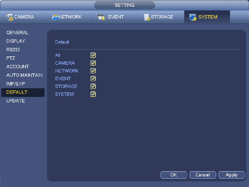
4.10.9 Default
Warning!
After you use default function, some your customized setup may lose forever! Please think twice before
you begin the operation!
You can restore factory default setup to fix some problems when the device is running slowly.
Configuration error occurred.
From Main menu->Setting->System->Default, you can go to the default interface. See Figure 4-236.
Check an item you want to restore default setup, or check the All to select all items.
Click OK or apply button, system pops up a dialogue box. Click OK to restore.
224
Figure 4-236
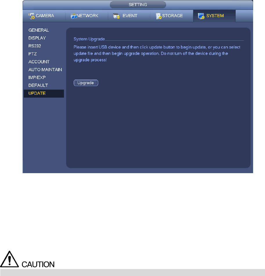
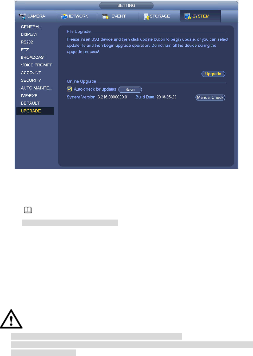
4.10.10 Upgrade
4.10.10.1 File Update
From Mani menu->Setting->Info->Update, you can go to the following interface. See Figure 4-237.
Step 1 Insert USB device that contain the upgrade file.
Step 2 Click Start button and then select the .bin file.
Step 3 You can see the corresponding dialogue box after the update process is complete.
225
Figure 4-237
4.10.10.2 Online Upgrade
When the NVR is online, you can use the online upgrade to update the firmware.
Before the online upgrade, system needs to detect if any new version is available. It includes auto check
and manual check.
Auto check: System automatically detects if any new version is available once in a while.
Manual check: Detect new version at real time.
During the upgrade process, make sure that the network connection and power supply are normal.
Step 1 Enter from main menu > Setup > System > Upgrade.
The Upgrade interface is displayed. See Figure 4-238.
226
Figure 4-238
Step 2 Version check.
Auto check: Select the Auto check for updates check box and click Save.
Note
System enables this function by default.
Manual check: Click Manual Check.
System starts to search new version and displays the result after the check is completed.
When system displays that it is the latest version, the current version is the latest one and
you do not need to upgrade it.
When system displays the new version information ( including release date and upgrade
notes), new version is available and go to Step 3.
Step 3 Click Upgrade to upgrade the system.
4.10.10.3 Uboot
When NVR boots up, during the uboot process, NVR automatically detects there is USB device and there
is upgrade file on the USB device or not. If the detection result is OK, NVR automatically begins upgrade.
CAUTION
The USB device shall contain two files: u-boot.bin.img and update.img.
The USB device shall connected to the USB port at the front panel. Otherwise, NVR cannot properly
detect the file or upgrade.
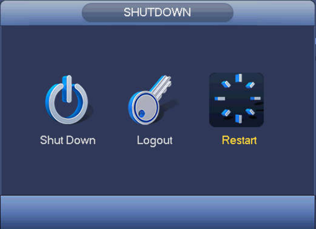
4.11 Logout /Shutdown/Restart
227
From Mani menu->Operation->Shutdown, you can see an interface shown as in Figure 4-239.
Shutdown: System shuts down and turns off power.
Logout: Log out menu. You need to input password when you login the next time.
Restart: reboot device.
If you shut down the device, there is a process bar for your reference, system waits for 3 seconds and
then shut down (You cannot cancel).
Please note, sometimes you need to input the proper password to shut down the device.
Figure 4-239

228
5 Web Operation
5.1 General Introduction
If it is your first time to login the device, please initialize your device first. Refer to chapter 5.2 Device
Initialization for detailed information.
The device web provides channel monitor menu tree, search, alarm setup, system setup, PTZ control and
monitor window and etc.
Note
Slight difference may be found on user interface. Please refer to the actual product for detailed
information.
Device supports various browsers such as Safari, Chrome and etc.
Use ChromeApp to login the WEB if the Chrome version is 45 or higher. Go to the Chrome online
store to download the ChromeApp installation package.
5.1.1 Preparation
Step 1 PC and NVR connection is OK.
Step 2 Set PC IP address, NVR IP address, subnet mask and gateway.
Set the IP address of the same section for the PC and NVR. Input corresponding gateway
and subnet mask if there are routers.)
The device default IP address is 192.168.1.108.
Step 3 Check the PC and device connection is OK or not. Refer to the following two ways to check the
network connection is OK or not. When the PC and device network connection is OK, login the
WEB via the PC.
On PC, use order ping ***.***.***.***(NVR IP address) to check connection is OK or not.
Login Usually the TTL value is 255.
Login the device local menu, from setting->Network->Network test and then input PC IP
address. Check the connection is OK or not.
Step 4 Login the WEB. Refer to chapter 5.10 Login for detailed information.
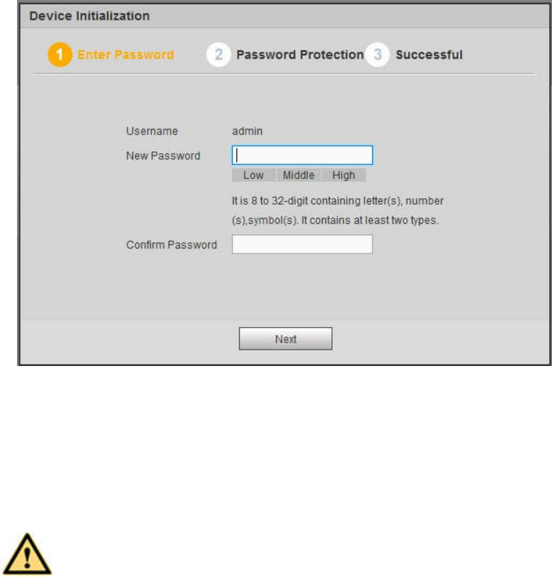
5.2 Device Initialization
If it is your first time to use the device, please set a login password of admin (system default user).
Note
For your device safety, please keep your login password of admin well after the initialization steps, and
change the password regularly.
Please follow the steps listed below.
Step 1 Open the IE and then input the NVR IP address in the address column.
Step 2 Click Enter button.
Device displays device initialization interface. See Figure 5-1.
229
Figure 5-1
Step 3 Set login password of admin.
User name: The default user name is admin.
Password/confirm password: The password ranges from 8 to 32 digitals. It can contain letters,
numbers and special characters (excluding “'”,“"”,“;”,“:”,“&”) . The password shall contain at least
two categories. Usually we recommend the strong password.
WARNING
STRONG PASSWORD RECOMMENDED-For your device own safety, please create a
strong password of your own choosing. We also recommend you change your password
periodically especially in the high security system.
Step 4 Click Next, device goes to the following interface. See Figure 5-2.
230
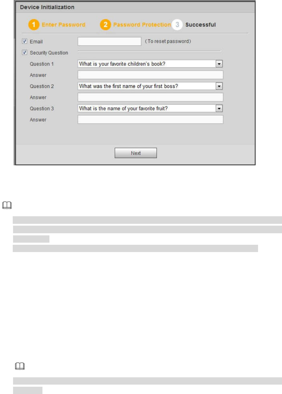
Figure 5-2
Step 5 Set security questions.
Note
After setting the security questions here, you can use the email you input here or answer the
security questions to reset admin password Refer to chapter 5.4 Reset password for detailed
information.
Cancel the email or security questions box and then click Next button to skip this step.
Email: Input an email address for reset password purpose. Scan the QR code to reset the
password, you need to receive the security code by the email. Input the security code to reset
the password of admin. In case you have not input email address here or you need to update
the email information, please go to the main Setup->System->Account to set. Refer to chapter
5.11.5.7 for detailed information.
Security question: Set security questions and corresponding answers. Properly answer the
questions to reset admin password. In case you have not input security question here or you
need to update the security question information, please go to the main
menu->Setting->System->Account->Security question to set. Refer to chapter 4.10.1.3 Security
question for detailed information.
Note
If you want to reset password by answering security questions, please go to the local menu
interface.
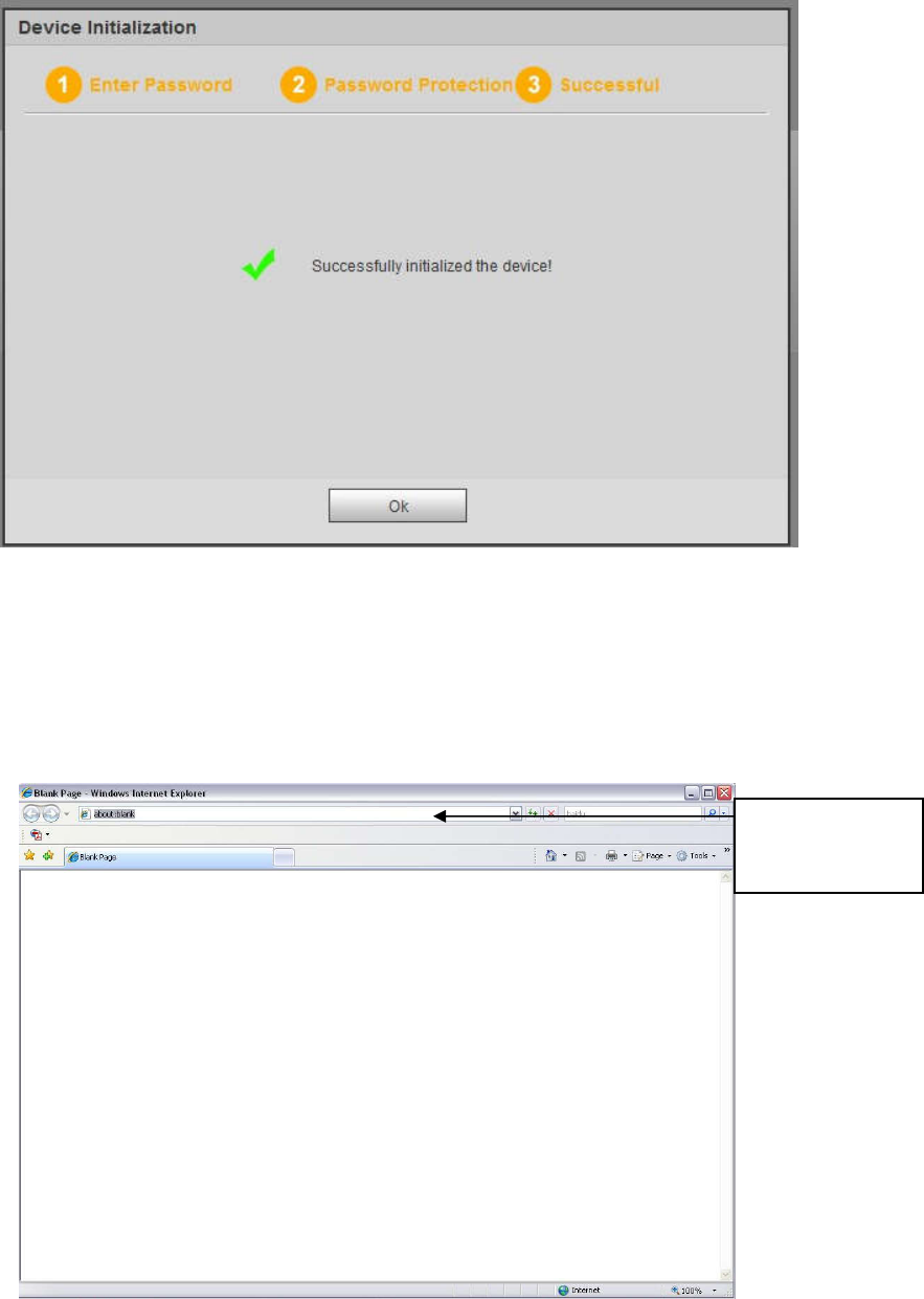
Step 6 Click OK to complete the device initialization setup. See Figure 5-3.
231
Figure 5-3
5.3 Log in
Open the IE and then input the NVR IP address in the address column.
For example, if your NVR IP address is 192.168.1.108, then please input http:// 192.168.1.108 in IE
address column. See Figure 5-4.
Figure 5-4
System pops up warning information to ask you whether install Web plug-in or not. Please click yes
button.
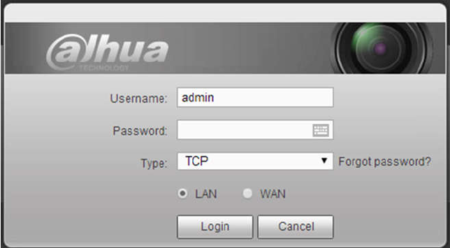
After installation, the interface is shown as below. See Figure 5-5.
Input IP
address here.
232
Figure 5-5
Please input your user name and password.
Factory default user name is admin and password is what you set in chapter 5.2 Device initialization.
5.4 Reset Password
If you forgot admin password, you can reset the password by email or by answering the security
questions (local menu only).
When the password reset function is enabled, you can scan the QR code on the Web to reset the
password.
When the password reset function is disabled, you can reset password via the security questions
configured before. If the secury questions are not configured, system displays that Password reset is
closed! You need to contact the customer service for help.
Step 1 Go to the device login interface. See Figure 5-5.
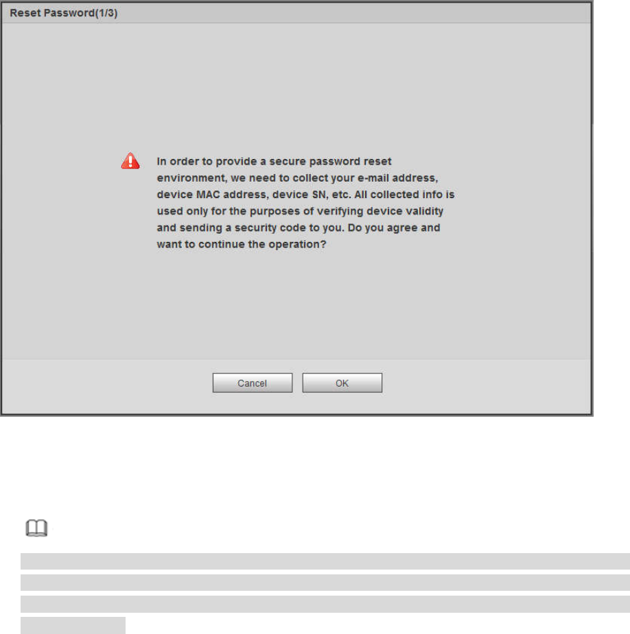
Step 2 Click Forgot password.
If you have set the reserved email, system displays a notice before the password reset. See
Figure 5-6.
If you have not set the reserved email, a dialogue box pops up that asks you to reset the
password by clicking Forgot password on the local interface.
233
Figure 5-6
Step 3 Click OK.
System enters the following interface. See Figure 5-7.
Note
After clicking OK, we will collect your personal information such as cell phone number, MAC
address and device serial number. The collected information is used for verifying device legality
and sending security code. Please read the notice carefully and confirm if you agree with the
collection or not.
234
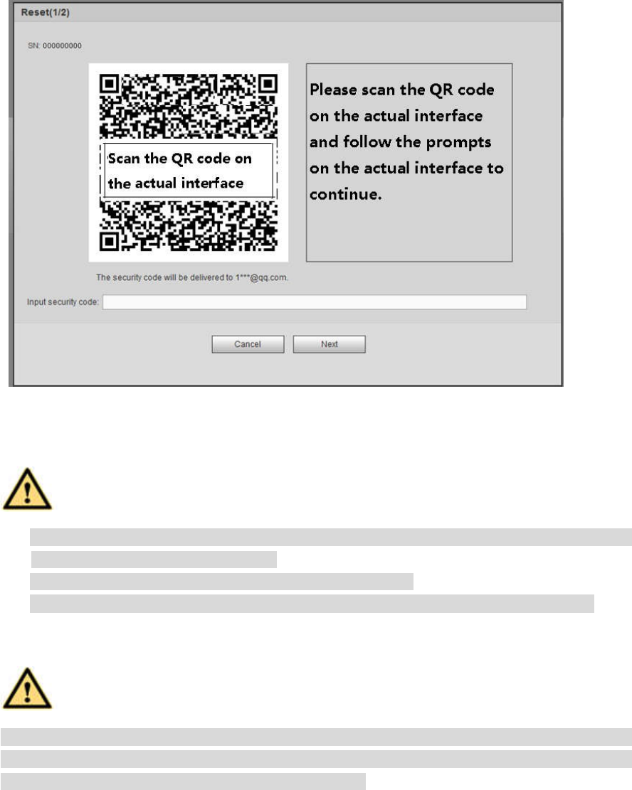
Figure 5-7
Step 4 Follow the prompts on the interface and then scan the QR code to get the security code.
WARNING
For the same QR code, max scan twice to get two security codes. Refresh the QR code if
you want to get security code again.
The security code on you email is only valid for 24 hours.
After five times security code failure, the admin account will be locked for 5 minutes.
Step 5 Input the security code on the email and then click Next button.
Step 6 Input new password and then confirm.
WARNING
The password can be set from 8 characters through 32 characters and contain at least two types
from number, letter and special character (excluding"'", """, ";", ":" and "&"). It is recommended to
set password of high security according to the prompts.
Step 7 Click OK button to complete the setup.
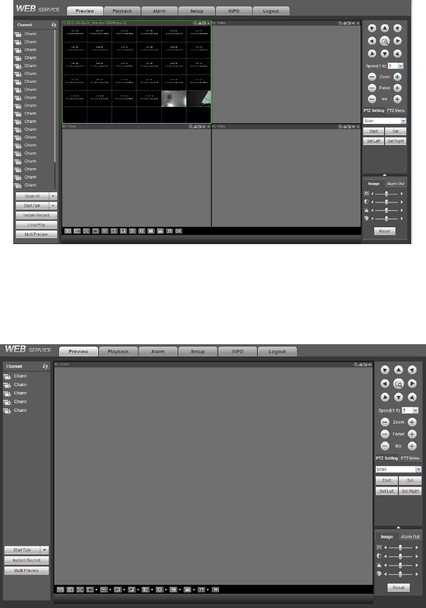
5.5 LAN Mode
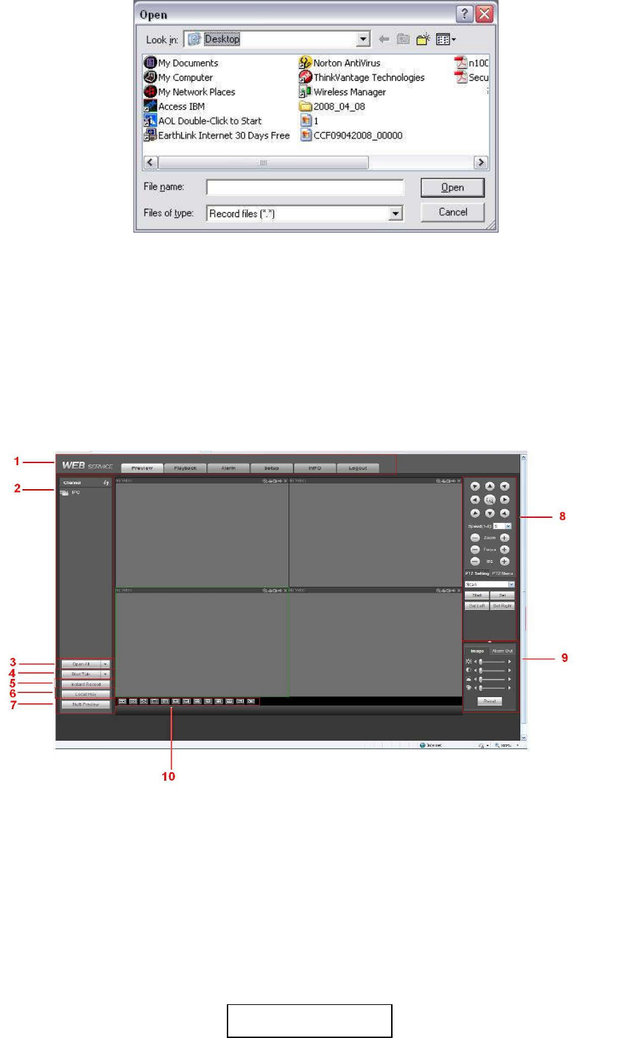
For the LAN mode, after you logged in, you can see the main window. See Figure 5-13.
This main window can be divided into the following sections.
Section 1: there are six function buttons: Live (chapter 5.6), setup (chapter 5.11), info (Chapter 5.12),
playback (chapter 5.13), alarm (chapter 5.15), and logout (chapter 5.16).
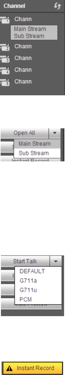
Section 2: There are monitor channels successfully connected to the NVR.
Please refer to Figure 5-8 for main stream and extra stream switch information.
235
Figure 5-8
Section 3: Open all. Open all button is to enable/disable all-channel real-time monitor. Here you can
select main stream/sub stream too. See Figure 5-9.
Figure 5-9
Section 4: Start Talk button.
You can click this button to enable audio talk. Click 【▼】 to select bidirectional talk mode. There are four
options: DEFAULT, G711a, G711u and PCM. See Figure 5-10.
After you enable the bidirectional talk, the Start talk button becomes End Talk button and it becomes
yellow. Please note, if audio input port from the device to the client-end is using the first channel audio
input port. During the bidirectional talk process, system will not encode the audio data from the 1-channel.
Figure 5-10
Section 5: Instant record button. Click it, the button becomes yellow and system begins manual
record. See Figure 5-11. Click it again, system restores previous record mode.
Figure 5-11
Section 6: Local play button.
The Web can playback the saved (Extension name is dav) files in the PC-end.
Click local play button, system pops up the following interface for you to select local play file. See Figure
5-12.
236
Figure 5-12
Section 7: Zero-channel encoding. Please refer to chapter 5.9 for detailed information.
Section 8: PTZ operation panel. Please refer to chapter 5.7 for detailed information.
Section 9: Image setup and alarm setup. Please refer to chapter 5.8 for detailed information.
Section 10: From the left to the right ,you can see video quality/fluency/ full
screen/1-window/4-window/6-window/8-window/9-window/13-window/16-window/20-window/25-win
dow/36-window.. You can set video fluency and real-time feature priority.
Figure 5-13
5.6 Real-time Monitor
In section 2, left click the channel name you want to view, you can see the corresponding video in current
window.
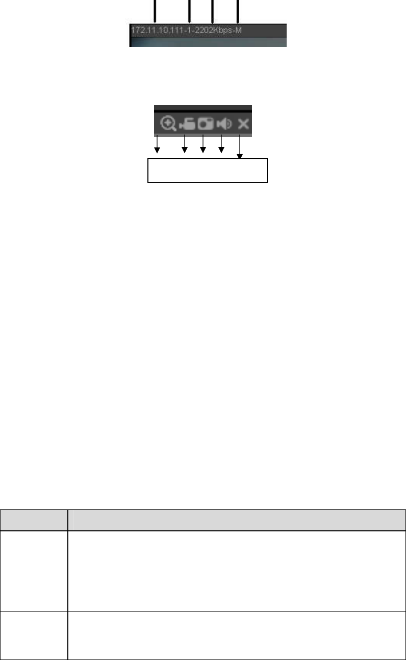
On the top left corner, you can view device IP(172.11.10.11), channel number(1), network monitor bit
stream(2202Kbps) and stream type(M=main stream, S=sub stream). See Figure 5-14.
1 2 3 4
237
Figure 5-14
On the top right corner, there are six unction buttons. See Figure 5-15.
Figure 5-15
1: Digital zoom: Click this button and then left drag the mouse in the zone to zoom in. right click
mouse system restores original status.
2: Local record. When you click local record button, the system begins recording and this button
becomes highlighted. You can go to system folder RecordDownload to view the recorded file.
3: Snapshot picture. You can snapshot important video. All images are memorized in system client
folder PictureDownload (default).
4: Audio :Turn on or off audio.(It has no relationship with system audio setup )
5: Close video.
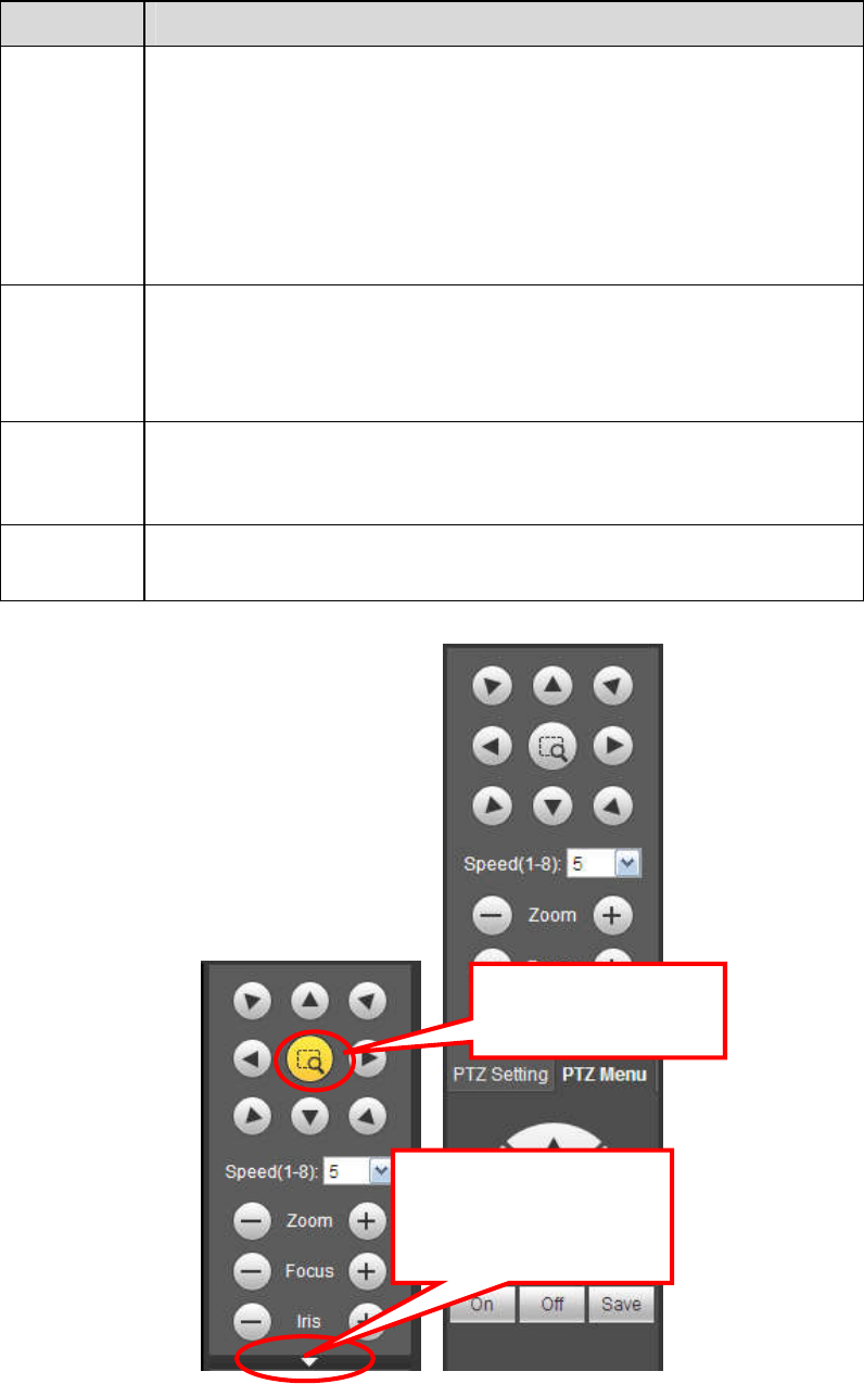
5.7 PTZ
Before PTZ operation, please make sure you have properly set PTZ protocol. (Please refer to chapter
5.11.5.4).
There are eight direction keys. In the middle of the eight direction keys, there is a 3D intelligent
positioning key.
Click 3D intelligent positioning key, system goes back to the single screen mode. Drag the mouse in the
screen to adjust section size. It can realize PTZ automatically.
Please refer to the following sheet for PTZ setup information.
Parameter
Function
Scan Select Scan from the dropdown list.
Click Set button, you can set scan left and right limit.
Use direction buttons to move the camera to you desired location
and then click left limit button. Then move the camera again and
then click right limit button to set a right limit.
Preset Select Preset from the dropdown list.
Turn the camera to the corresponding position and Input the
preset value. Click Add button to add a preset.
1 2 3 4 5
238
Parameter
Function
Tour Select Tour from the dropdown list.
Input preset value in the column. Click Add preset button, you
have added one preset in the tour.
Repeat the above procedures you can add more presets in one
tour.
Or you can click delete preset button to remove one preset from
the tour.
Pattern Select Pattern from the dropdown list.
You can input pattern value and then click Start button to begin
PTZ movement such as zoom, focus, iris, direction and etc. Then
you can click Add button to set one pattern.
Aux Please input the corresponding aux value here.
You can select one option and then click AUX on or AUX off
button.
Light and
wiper
You can turn on or turn off the light/wiper.
Figure 5-16
5.8 Image/Alarm-out
You can click this icon to
display or hide the PTZ
control platform.
3D Intelligent Positioning
Key
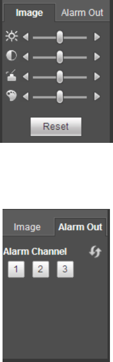
239
Select one monitor channel video and then click Image button in section 9, the interface is shown as
Figure 5-17.
5.8.1 Image
Here you can adjust its brightness, contrast, hue and saturation. (Current channel border becomes
green).
Or you can click Reset button to restore system default setup.
Figure 5-17
5.8.2 Alarm output
Here you can enable or disable the alarm signal of the corresponding port. See Figure 5-18.
Figure 5-18
5.9 Zero-channel Encode
Select a window and then click zero-channel encode button, the interface is shown as below. See Figure
5-19.
240
Figure 5-19
5.10 WAN Login
In WAN mode, after you logged in, the interface is shown as below. See Figure 5-20.
Figure 5-20
Please refer to the following contents for LAN and WAN login difference.
1) In the WAN mode, system opens the main stream of the first channel to monitor by default. The
open/close button on the left pane is null.
2) You can select different channels and different monitor modes at the bottom of the interface. See
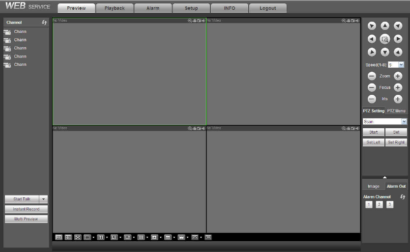
241
Figure 5-21.
Figure 5-21
Important
The window display mode and the channel number are by default. For example, for the 16-channel,
the max window split mode is 16.
3) Multiple-channel monitor, system adopts extra stream to monitor by default. Double click one channel,
system switches to single channel and system uses main stream to monitor. You can view there are two
icons at the left top corner of the channel number for you reference. M stands for main stream. S stands
for sub stream (extra stream).
4) If you login via the WAN mode, system does not support alarm activation to open the video function in
the Alarm setup interface.
Important
For multiple-channel monitor mode, system adopts extra stream to monitor by default. You cannot
modify manually. All channels are trying to synchronize. Please note the synchronization effect still
depends on your network environments.
For bandwidth consideration, system cannot support monitor and playback at the same time. System
auto closes monitor or playback interface when you are searching setup in the configuration interface.
It is to enhance search speed.
5.11 Setup
5.11.1 Camera
5.11.1.1 Registration
5.11.1.1.1 Registration
From Main menu->Setup->Camera->Registration->Registration, you can see the following interface. See
Figure 5-22.
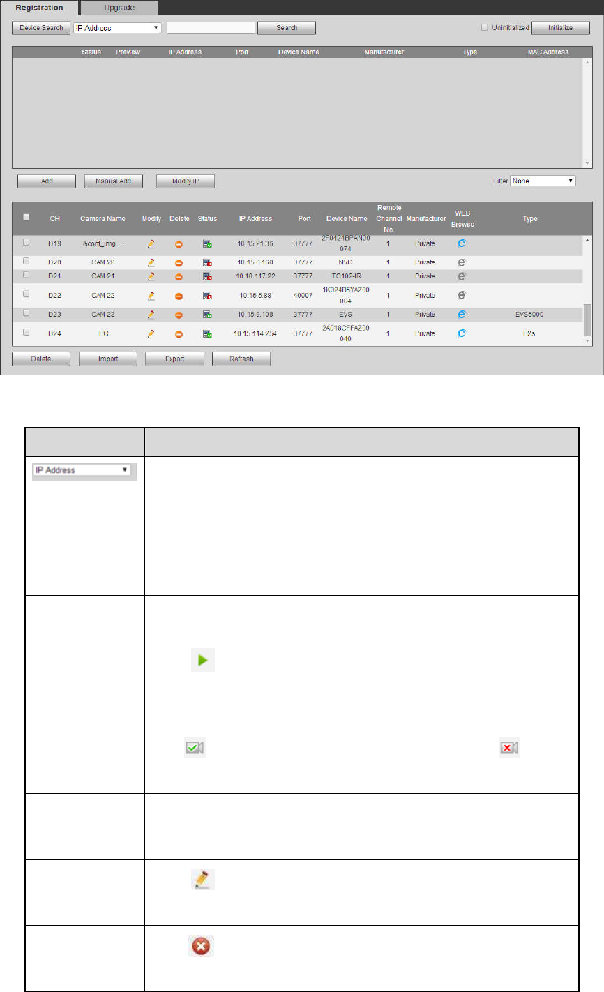
242
Figure 5-22
Please refer to the following sheet for parameter information.
Parameter Function
Select IP address or the MAC address from the dropdown list
and then input the corresponding information, click Search
button to view the results.
Search Click Search button, you can view the searched device
information on the list. It includes device IP address, port, device
name, manufacturer and type.
Uninitialized Click to search the initialized devices. Select an uninitialized
device and then click the Initialize button to set the account.
Preview Click to view the preview video of the remote device.
State It is to display the device has been initialized or not. That is to
say, the remote device has set the initial account information or
not. means the remote device has initialized, means
the remote device has not been intialized.
Add Select a device in the list and then click Add button, system can
connect the device automatically and add it to the Added device
list. Or you can double click one item in the list to add a device.
Modify Click or any device in the Added device list, you can change
the corresponding channel setup.
Delete
Click , you can delete the remote connection of the
corresponding channel.
243
Parameter Function
Type There are two connection types. You can use the network to
connect to the camera or use the Wi-Fi. The means
current network camera connection mode is general; the
means current network camera mode is hotspot.
Delete Select a device in the Added device list and then click Delete
button, system can disconnect the device and remove it from the
Added device list.
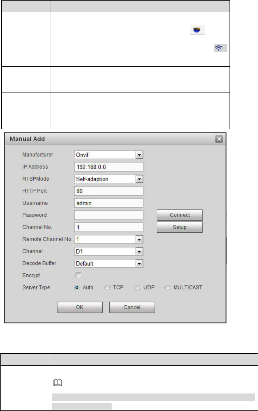
Manual Add Click it, the interface is shown as in Figure 5-23. Here you can
add network camera manually.
You can select a channel from the dropdown list (Here only
shows disconnection channel.)
Figure 5-23
Please refer to the following sheet for parameter information.
Parameter Function
Manufacturer Please select from the dropdown list.
Note
Different series products may support different manufacturers, please refer
to the actual product.
244
Parameter Function
IP address Input remote device IP address.
RTSP port
Input RTSP port of the remote device. The default setup is 554.
Note
Skip this item if the manufacture is private or customize.
HTTP port
Input HTTP port of the remote device. The default setup is 80.
Note
Skip this item if the manufacture is private or customize.
TCP port Input TCP port of the remote device. The default setup is 37777.
User
name/password
The user name and password to login the remote device.
Channel No.
Input channel amount or click the Connect button to get the channel amount
of the remote device.
Note
We recommend click Connect button to get remote device channel amount,
the manual add operation may result in failure if the input channel amount is
not right.
Remote
channel No.
After getting the remote device channel amount, click Setup to select a
channel.
Note
Click to select one or more remote channel numbers here.
Channel The local channel number you want to add. One channel name has
corresponding one channel number.
Decode buffer
There are three item: realtime, local, fluent.
Service type
There are four items: auto/TCP/UDP/MULTICAST(ONVIF device only)
Note
The default connection mode is TCP if the connection protocol is
private.
There are four items including Auto, TCP, UDP and MULTICAST if the
connection protocol is ONVIF.
There are two items including TCP and UDP if the connection protocol
is from the third-party.
Encrypt
When the connection protocol is ONVIF, enable the encryption function and
system transmits data in the encrypted mode.
Note
System supports this function when HTTPS is enabled in IPC.
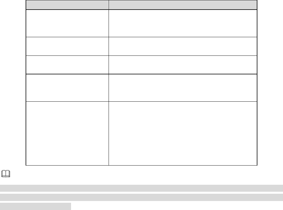
Change IP
On the searched devices list, check one or more device(s) at the same time. Click Modify IP button, you
245
can see the following interface. See Figure 5-24
Please refer to the following sheet for log parameter information.
Parameter Function
DHCP Check the box here, system can auto allocate the IP
address. The IP address, subnet mask, default
gateway are reference only.
Static Check the box here, you can set IP address, subnet
mask, default gateway manually.
IP address/subnet
mask/default gateway
You can input corresponding information here.
User name/password The account you login the remote device. Please
input here to password verification to change the
remote device password.
Incremental value When you want to change several IP addresses,
once you input the IP address of the first device, the
IP address of the next device will increase
accordingly. For example, when the incremental
value is 1, if the IP address of the first device is
172.10.3.128, the IP address of the second device
will auto be set as 172.10.3.129.
Note
For the static IP address, system will alert you if there is any IP conflict. If you are changing several IP
addresses at the same time, system auto skip the conflicted IP and auto allocate again according to the
incremental value you set.
246
Figure 5-24
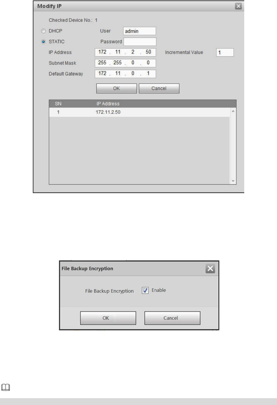
Export IP
System supports to export the registered device list and save it in the USB device.
Step 1 Inset the USB device and click Export.
The File Backup Encryption interface is displayed. See Figure 5-25.
Figure 5-25
Step 2 File backup encryption is enabled by default. Click OK to select the save path.
Step 3
Click Save. After the export is completed, system pops up a dialogue box to show that backup is
completed.
Note
Backup encryption is enabled by default when exporting IP. The file contains information such as IP
247
address, port, remote channel number, manufacturer, username and password.
If file backup encryption is enabled, the extension name of the exported file is .backup. Except the
NVR device, any other software cannot open and edit the file.
If the backup encryption is disabled, the extension name of the exported file is .csv. It might lead to
data leakage.
Import IP
You can import the added device list to add the device conveniently.
Click Import button, and then select the import file.
Note
If the imported IP is already in the added device list, system pops up dialogue box for you to confirm
overwrite or not.
Click OK button, the new IP setup can overwrite the old one.
Click Cancel button, system adds the new IP setup.
Important
You can edit the exported file. Please make sure the file format is the same. Otherwise you cannot
import the file again!
System does not support customized protocol import/export.
The import/export function is for the devices of the same language.
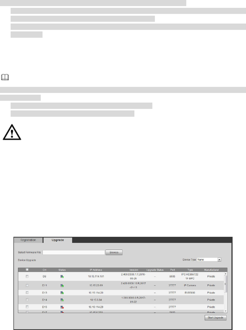
5.11.1.1.2 IPC Upgrade
This interface is to upgrade network camera.
From Main menu->Setting->Camera->Registration->IPC upgrade, enter the following interface. See
Figure 5-26.
Click Browse button to select upgrade file. Or you can use filter to select several network cameras at the
same time.
Figure 5-26
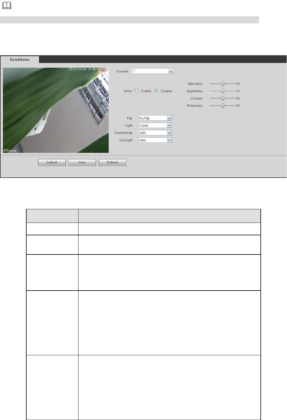
5.11.1.2 Image
248
Note
Slight difference may be found since the connected network camera may not be same model.
Here you can view device property information. The setups become valid immediately after you set. See
Figure 5-27.
Figure 5-27
Please refer to the following sheet for detailed information.
Parameter Function
Channel Please select a channel from the dropdown list.
Period It divides one day (24 hours) to two periods. You can set
different hue, brightness, and contrast for different periods.
Hue It is to adjust monitor video brightness and darkness level. The
default value is 50.
The bigger the value is, the large the contrast between the bright
and dark section is and vice versa.
Brightness It is to adjust monitor window brightness. The default value is 50.
The larger the number is , the bright the video is. When you
input the value here, the bright section and the dark section of
the video will be adjusted accordingly. You can use this
function when the whole video is too dark or too bright. Please
note the video may become hazy if the value is too high. The
value ranges from 0 to 100.The recommended value ranges
from 40 to 60.
Contrast It is to adjust monitor window contrast. The value ranges from 0
to 100. The default value is 50.
The larger the number is, the higher the contrast is. You can use
this function when the whole video bright is OK but the contrast
is not proper. Please note the video may become hazy if the
value is too low. If this value is too high, the dark section may
lack brightness while the bright section may over exposure .The
recommended value ranges from 40 to 60.

249
Saturation It is to adjust monitor window saturation. The value ranges from
0 to 100. The default value is 50.
The larger the number is, the strong the color is. This value has
no effect on the general brightness of the whole video. The
video color may become too strong if the value is too high. For
the grey part of the video, the distortion may occur if the white
balance is not accurate. Please note the video may not be
attractive if the value is too low. The recommended value ranges
from 40 to 60.
Gain The gain adjust is to set the gain value. The smaller the value is,
the low the noise is. But the brightness is also too low in the dark
environments. It can enhance the video brightness if the value is
high. But the video noise may become too clear.
White level It is to enhance video effect.
Color mode It includes several modes such as standard, color. You can
select corresponding color mode here, you can see hue,
brightness, and contrast and etc will adjust accordingly.
Auto Iris It is to enable/disable auto iris function.
Flip It is to switch video up and bottom limit.
This function is disabled by default.
Mirror It is to switch video left and right limit.
This function is disabled by default.
BLC
Mode
BLC The device auto exposures according to the environments
situation so that the darkest area of the video is cleared
WDR For the WDR scene, this function can lower the high bright
section and enhance the brightness of the low bright section. So
that you can view these two sections clearly at the same time.
The value ranges from 1 to 100. When you switch the camera
from no-WDR mode to the WDR mode, system may lose several
seconds record video.
HLC After you enabled HLC function, the device can lower the
brightness of the brightest section according to the HLC control
level. It can reduce the area of the halo and lower the brightness
of the whole video.
Off It is to disable the BLC function. Please note this function is
disabled by default.
Profile It is to set the white balance mode. It has effect on the general
hue of the video. This function is on by default.
You can select the different scene mode such as auto, sunny,
cloudy, home, office, night, disable and etc to adjust the video to
the best quality.
Auto: The auto white balance is on. System can auto
compensate the color temperature to make sure the vide
color is proper.
Sunny: The threshold of the white balance is in the sunny
mode.
Night: The threshold of the white balance is in the night
250
mode.
Customized: You can set the gain of the red/blue channel.
The value reneges from 0 to 100.
Day/Night It is to set device color and the B/W mode switch. The default
setup is auto.
Color: Device outputs the color video.
Auto: Device auto select to output the color or the B/W
video according to the device feature (The general bright of
the video or there is IR light or not.)
B/W: The device outputs the black and white video.
Sensor: It is to set when there is peripheral connected IR
light.
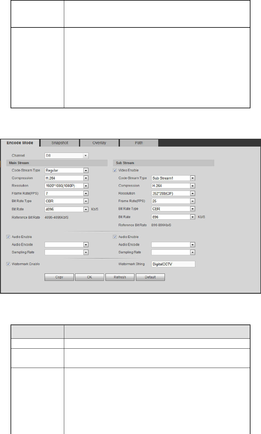
5.11.1.3 Encode
5.11.1.3.1 Encode
The encode interface is shown as below. See Figure 5-28.
Figure 5-28
Please refer to the following sheet for detailed information.
Parameter Function
Channel Please select a channel from the dropdown list.
Video enable Check the box here to enable extra stream video. This item is
enabled by default.
Code stream
type
It includes main stream, motion stream and alarm stream. You
can select different encode frame rates form different recorded
events.
System supports active control frame function (ACF). It allows
you to record in different frame rates.
For example, you can use high frame rate to record important
events, record scheduled event in lower frame rate and it allows

251
you to set different frame rates for motion detection record and
alarm record.
Compression Video encode mode.
H.264: Main Profile encode mode.
H.264H: High Profile encode mode.
H.264B: Baseline Profile encode mode.
H.265: Main Profile encode mode.
MJPEG: System needs high bit streams to guarantee
video definition. Use the recommended max bit stream
value to get the better video effect.
Smart Codec This function is to reduce bit streams.
Note
Some series products support smart codec function.
After changing smart code, please reboot network
camera and some network camera functions (such as
IVS, ROI, SVC, lobby mode and etc.) becomes null.
Please think twice before the operation.
Resolution The resolution here refers to the capability of the network
camera.
Frame Rate The video frame amount displayed in each second. The higher
the frame rate is, the clearer and more fluent the video is. The
frame rate may vary depending on the resolution.
Bit Rate Main stream: You can set bit rate here to change video
quality. The large the bit rate is, the better the quality is.
Please refer to recommend bit rate for the detailed
information.
Extra stream: In CBR,
the bit rate here is the max value.
In dynamic video, system needs to low frame rate or
video quality to guarantee the value. The value is null in
VBR mode.
Bit rate type System supports two types: CBR and VBR.
Main stream: It is to set frame rate to change video
quality. The higher the frame rate is, the better the video
quality is. The referenced bit rate is the recommended
value.
Sub stream: In CBR mode, the bit stream is near the
specified value. In VBR mode, the video quality changes
according to the bit stream value. But its max value is
near the specified value. Reference bit rate: The
reference bit rate depends on the resolution and frame
rate you set.
Reference bit
rate Recommended bit rate value according to the resolution and
frame rate you have set.
I Frame Here you can set the P frame amount between two I frames. The
value ranges from 1 to 150. Default value is 50.
Recommended value is frame rate *2.
252
Video/audio
You can enable or disable the video/audio. The main stream is
enabled by default. After enable the audio function,
the record file
is composite file consisting of the video and audio. For the sub
stream 1, please enable video first and then enable audio
function.
Audio format Set audio encode format.
Note
Different series products support different audio enco
de mode.
Please refer to the actual interface for detailed information.
Sampling rate Audio sampling rate refers to the sampling amount within 1
second. The higher the value is, the better the audio is. The
default setup is 8K.
Watermark
enable
This function allows you to verify the video is tampered or not.
Here you can select watermark bit stream, watermark mode and
watermark character. Default character is DigitalCCTV. The max
length is 85-digit. The character can only include number,
character and underline.
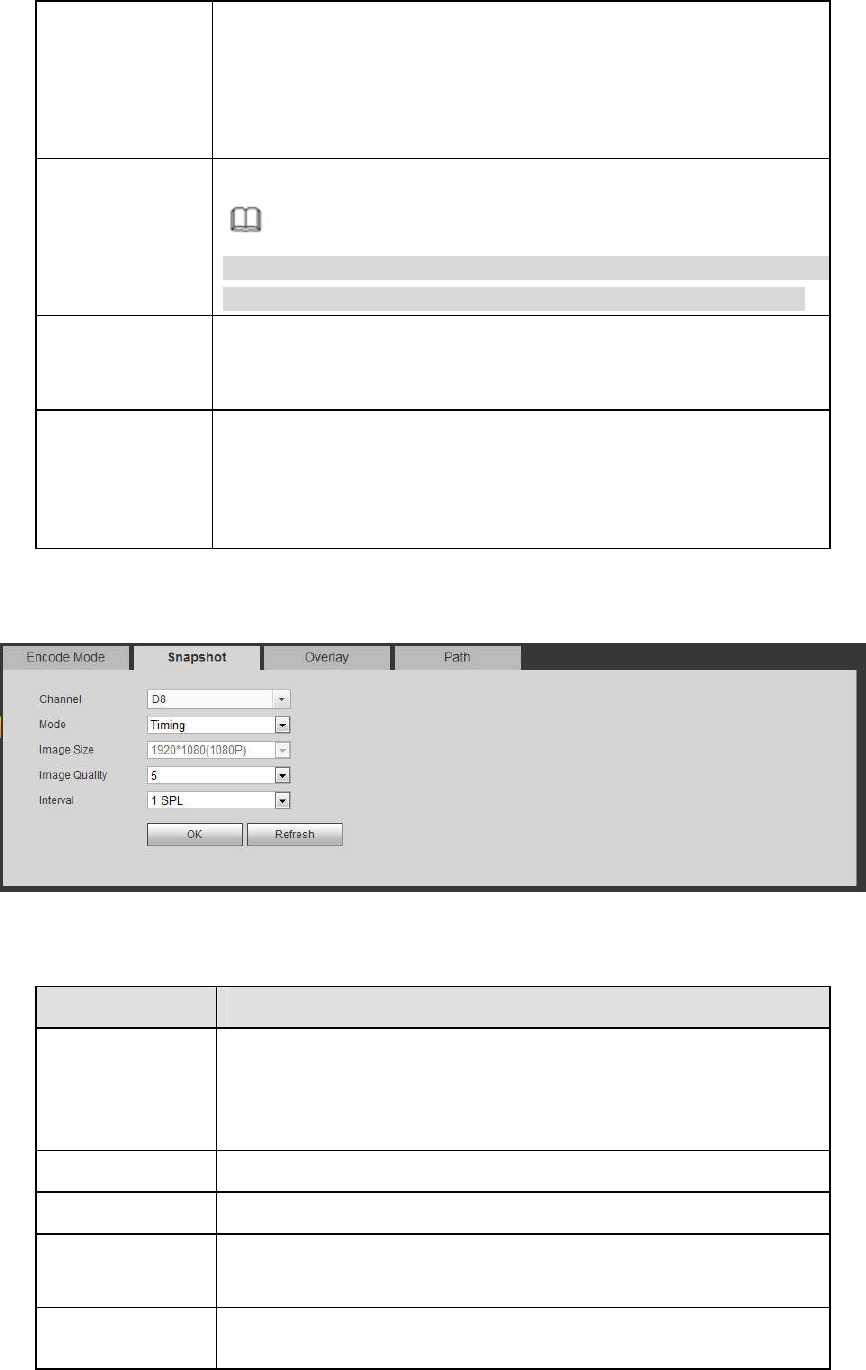
5.11.1.3.2 Snapshot
The snapshot interface is shown as in Figure 5-29.
Figure 5-29
Please refer to the following sheet for detailed information.
Parameter Function
Snapshot type There are two modes: Regular (schedule) and Trigger.
Regular snapshot is valid during the specified period you
set.
Trigger snapshot only is valid when motion detect alarm,
tampering alarm or local activation alarm occurs.
Image size It is the same with the resolution of the main stream.
Quality It is to set the image quality. There are six levels.
Interval It is to set snapshot frequency. The value ranges from 1s to 7s.
Or you can set customized value. The max setup is
3600s/picture.
Copy Click it; you can copy current channel setup to other channel(s).
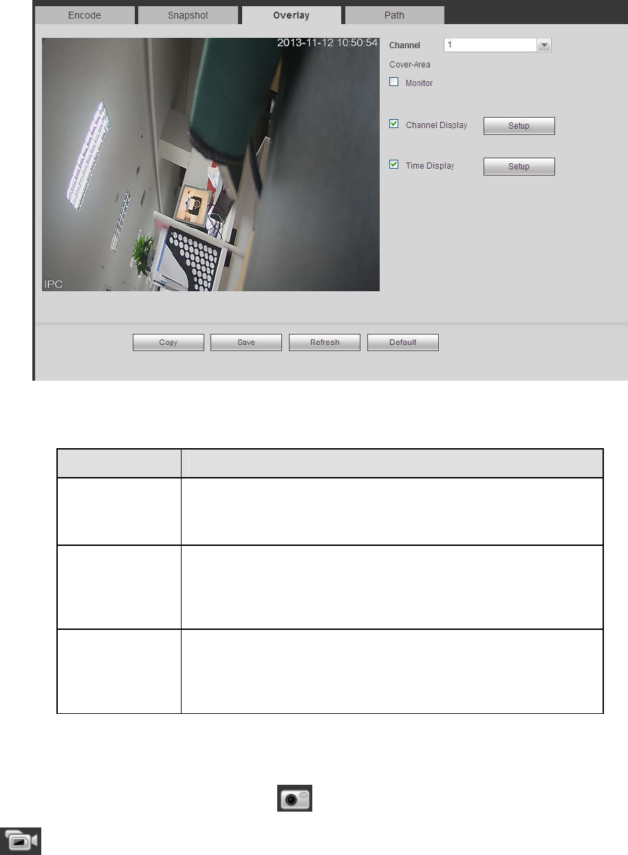
5.11.1.3.3 Video Overlay
The video overlay interface is shown as in Figure 5-30.
253
Figure 5-30
Please refer to the following sheet for detailed information.
Parameter Function
Cover-area
Check Preview or Monitor first.
Click Set button, you can privacy mask the specified video in the
preview or monitor video.
System max supports 4 privacy mask zones.
Time Title You can enable this function so that system overlays time
information in video window.
You can use the mouse to drag the time title position.
You can view time title on the live video of the WEB or the
playback video.
Channel Title You can enable this function so that system overlays channel
information in video window.
You can use the mouse to drag the channel title position.
You can view channel title on the live video of the WEB or the
playback video.
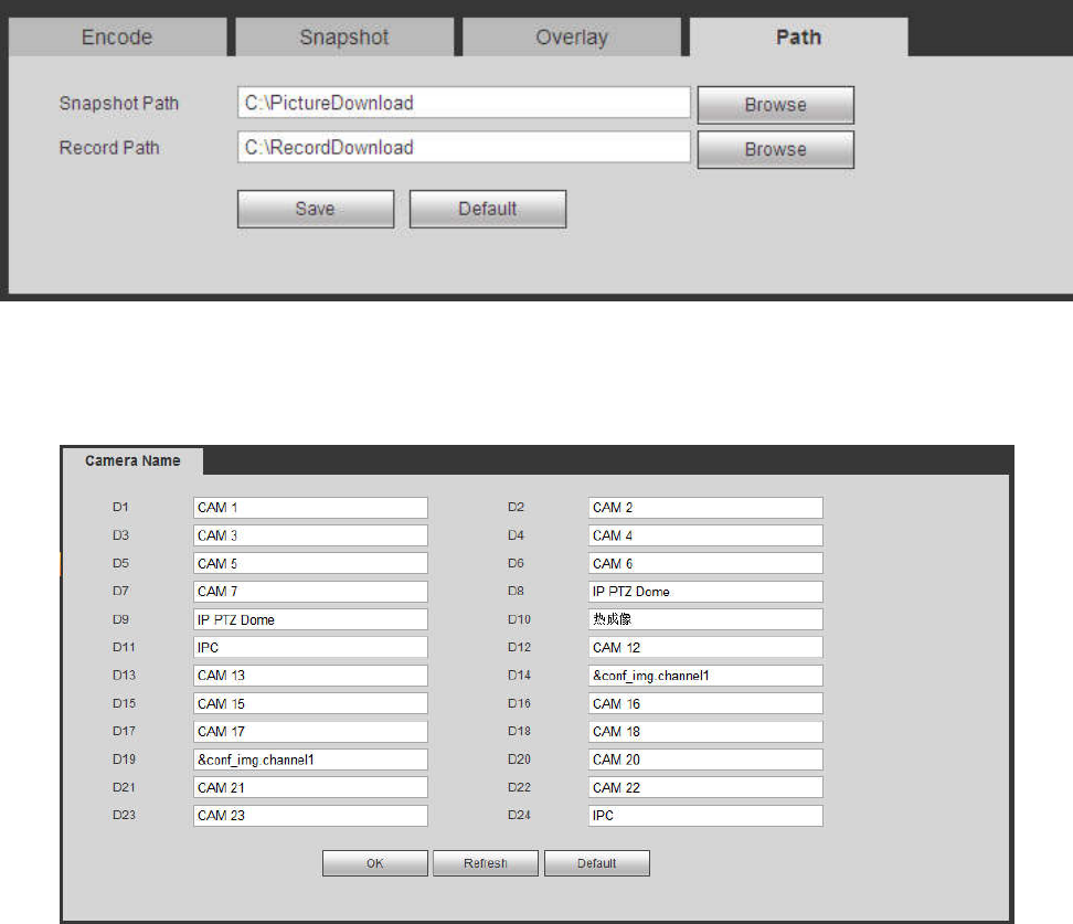
5.11.1.3.4 Path
The storage path interface is shown as in Figure 5-31.
Here you can set snap image saved path ( in the preview interface) and the record storage path
( in the preview interface).The default setup is C:\PictureDownload and C:\RecordDownload.
Please click the Save button to save current setup.
254
Figure 5-31
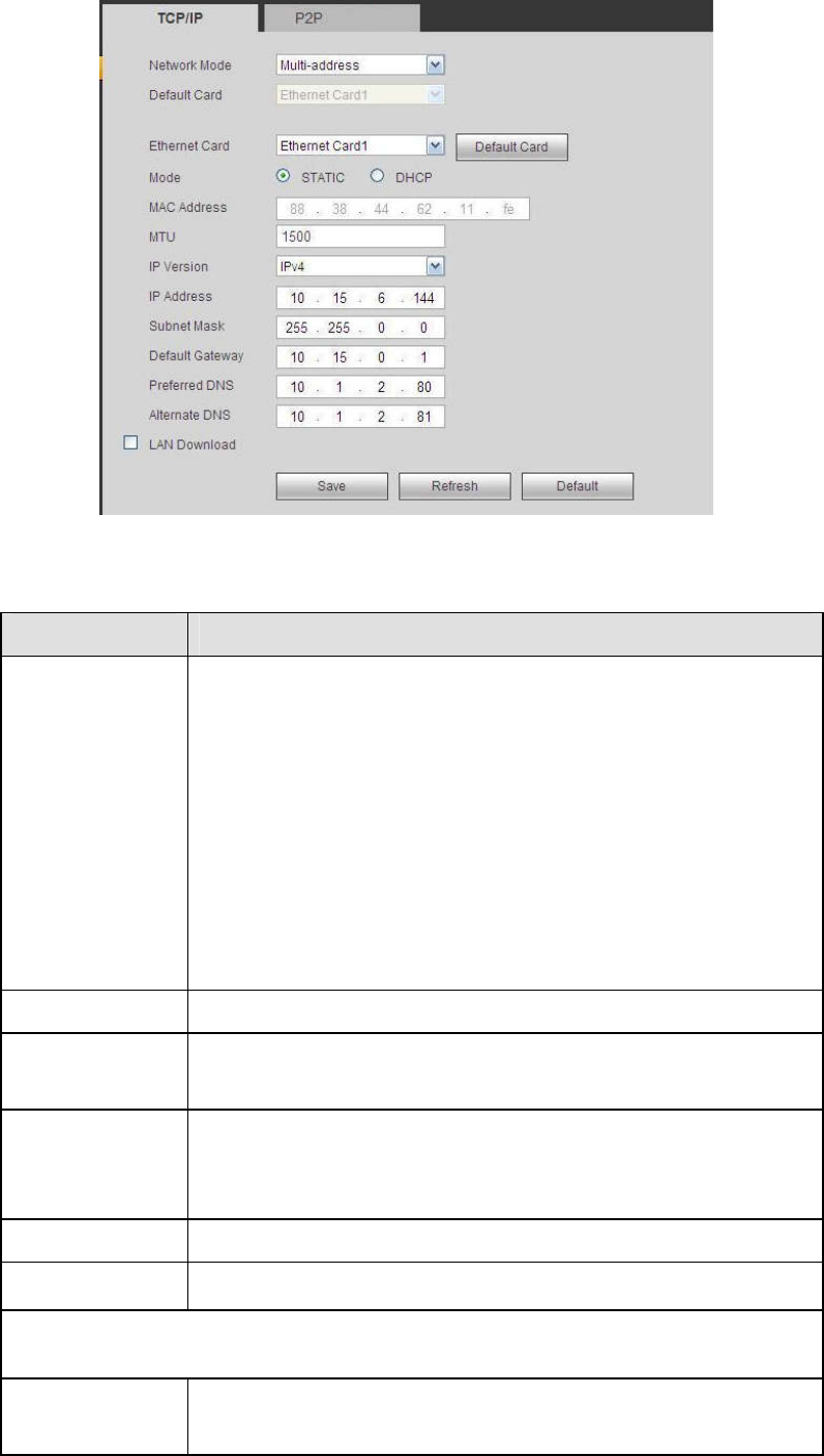
5.11.1.4 Channel Name
Here you can set channel name. See Figure 5-32.
Figure 5-32
5.11.2 Network
5.11.2.1 TCP/IP
The TCP/IP interface is shown as in Figure 5-33.
255
Figure 5-33
Please refer to the following sheet for detailed information.
Parameter Function
Mode There are two modes: static mode and the DHCP mode.
The IP/submask/gateway are null when you select the
DHCP mode to auto search the IP.
If you select the static mode, you need to set the
IP/submask/gateway manually.
If you select the DHCP mode, you can view the
IP/submask/gateway from the DHCP.
If you switch from the DHCP mode to the static mode, you
need to reset the IP parameters.
Besides, IP/submask/gateway and DHCP are read-only
when the PPPoE dial is OK.
Mac Address It is to display host Mac address.
IP Version It is to select IP version. IPV4 or IPV6.
You can access the IP address of these two versions.
IP Address Please use the keyboard to input the corresponding number to
modify the IP address and then set the corresponding subnet
mask and the default gateway.
Preferred DNS DNS IP address.
Alternate DNS Alternate DNS IP address.
For the IP address of IPv6 version, default gateway, preferred DNS and
alternate DNS, the input value shall be 128-digit. It shall not be left in blank.
LAN load System can process the downloaded data first if you enable this
function. The download speed is 1.5X or 2.0X of the normal
speed.
256
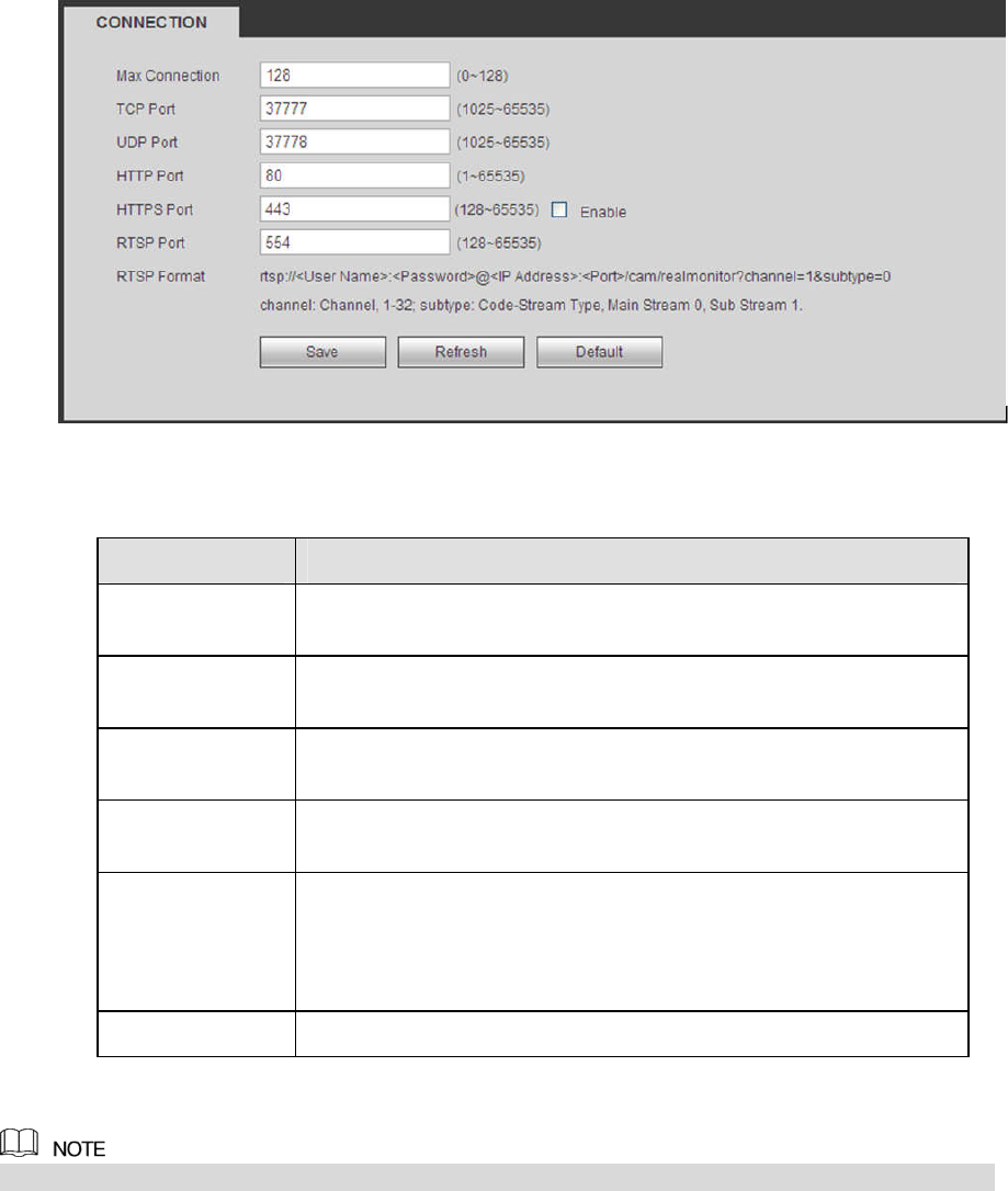
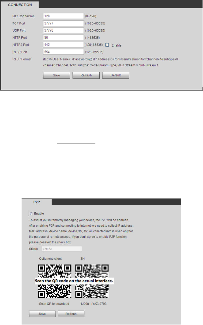
5.11.2.2 Port
The connection interface is shown as in Figure 5-34.
Figure 5-34
Please refer to the following sheet for detailed information.
Parameter Function
Max connection
The max client login amount (such as WEB, platform, cellphone
and etc). The value ranges from 1 to 128(default).
TCP port The default value is 37777. You can input the actual port
number if necessary.
UDP port The default value is 37778. You can input the actual port
number if necessary.
HTTP port The default value is 80. You can input the actual port number if
necessary.
HTTPS
Select the Enable check box and configure the port according to
your actual needs. The default value is 443. After HTTPS is
enabled, HTTP will be switched to HTTPS by force to transmi
t
data in a safer way.
RTSP port The default value is 554.
5.11.2.3 Wi-Fi AP
This function is available only for NVR devices with built-in Wi-Fi module. See the actual situation.
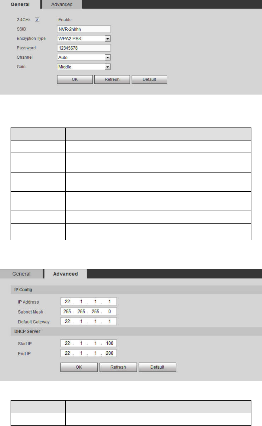
5.11.2.3.1 General Setup
The Wi-Fi AP interface is shown as in Figure 5-35. Select the Enable check box and you can set Wi-Fi
hotspot including SSID, encryption type, password, channel and gain, so that the Wi-Fi IPC can use the
hotspot to connect to the network.
257
Figure 5-35
Please refer to the following sheet for detailed information.
Parameter Function
2.4GHz Select the check box to enable Wi-Fi.
SSID It is to set SSID name. You can use this name to search the
device.
Encryption Type
Select the encryption type from the dropdown list, including
WPA2 PSK, WPA PSK and OPEN.
Password It is to set SSID password. You can use this password to
connect to the network.
Channel Select the channel to connect the Wi-Fi IPC.
Gain Adjust the Wi-Fi signal intensity.
5.11.2.3.2 Advanced
Click Advanced button, the interface is shown as below. See Figure 5-36.
Figure 5-36
Please refer to the following sheet for detailed information.
Parameter Function
IP Address Input the IP address, subnet mask and default gateway of the
258
Subnet Mask NVR Wi-Fi AP.
The IP address and default gateway shall be in the same
network segment.
Default Gateway
Start IP/End IP Input start IP and end IP of DHCP server. The NVR device can
allocate the IP address in the range you specified here.
Upgrade Click it to upgrade Wi-Fi AP module.
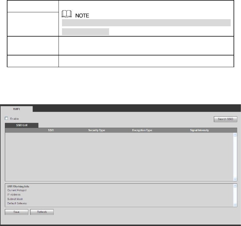
5.11.2.4 Wi-Fi
Please note this function is for the device of Wi-Fi module.
The Wi-Fi interface is shown as in Figure 5-37.
Figure 5-37
Please check the box to enable Wi-Fi function and then click the Search SSID button. Now you can view
all the wireless network information in the following list. Double click a name to connect to it. Click
Refresh button, you can view latest connection status.
5.11.2.5 3G
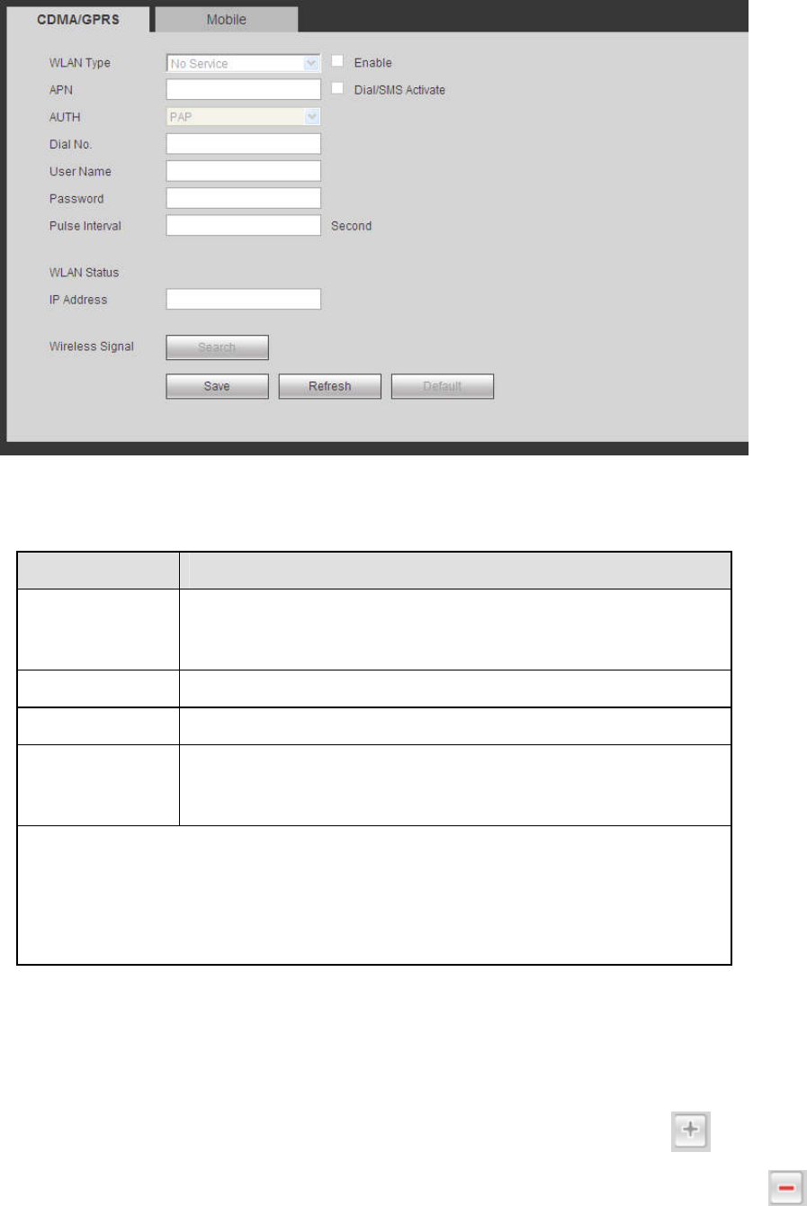
5.11.2.5.1 CDMA/GPRS
The CDMA/GPRS interface is shown as in Figure 5-38.
259
Figure 5-38
Please refer to the following sheet for detailed information.
Parameter Function
WLAN type Here you can select 3G network type to distinguish the 3G
module from different ISP. The types include WCDMA,
CDMA1x and etc.
APN/Dial No. Here is the important parameter of PPP.
Authorization It includes PAP,CHAP,NO_AUTH.
Pulse interval It is to set time to end 3G connection after you close extra
stream monitor. For example, if you input 60 here, system ends
3G conn
ection after you close extra stream monitor 60 seconds.
Important
If the pulse interval is 0, then system does not end 3G connection after
you close the extra stream monitor.
Pulse interval here is for extra stream only. This item is null if you are
using main stream to monitor.
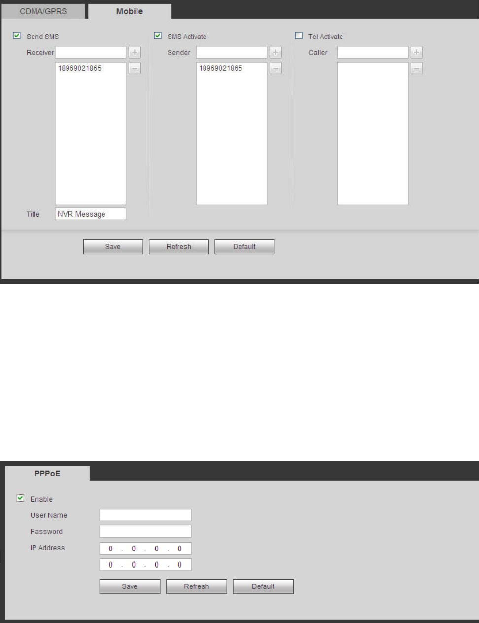
5.11.2.5.2 Mobile
The mobile setup interface is shown as in Figure 5-39.
Here you can activate (send out “on”) or turn off (Send out “off”) the 3G connected phone or mobile phone,
or the phone you set to get alarm message.
Check send SMS box and then input the phone number in the receiver column. Click to add one
receiver. Repeat the above steps you can add more phones. Select a phone number and then click ,
you can delete it. Click OK button to complete the setup.
260
Figure 5-39
5.11.2.6 PPPoE
The PPPoE interface is shown as in Figure 5-40.
Input the PPPoE user name and password you get from the IPS (internet service provider) and enable
PPPoE function. Please save current setup and then reboot the device to get the setup activated.
Device connects to the internet via PPPoE after reboot. You can get the IP address in the WAN from the
IP address column.
Please note, you need to use previous IP address in the LAN to login the device. Please go to the
IP address item to via the device current device information. You can access the client-end via
this new address.
Figure 5-40
5.11.2.7 DDNS
DDNS (Dynamic Domain Name Server) is to dynamically refresh the DNS domain name and IP address if
the device IP address has changed frequently. The user can use the domain to access the device.
261
Preparation
Before the operation, check the DDNS type that the device supports.
If the DDNS type is Quick DDNS. You do not need to register the domain name.
If the DDNS is some other type, log in the website of the DDNS provider and register information like
domain name.
After you register the device and log in the DDNS website, you can view all connected device information
of the current user.
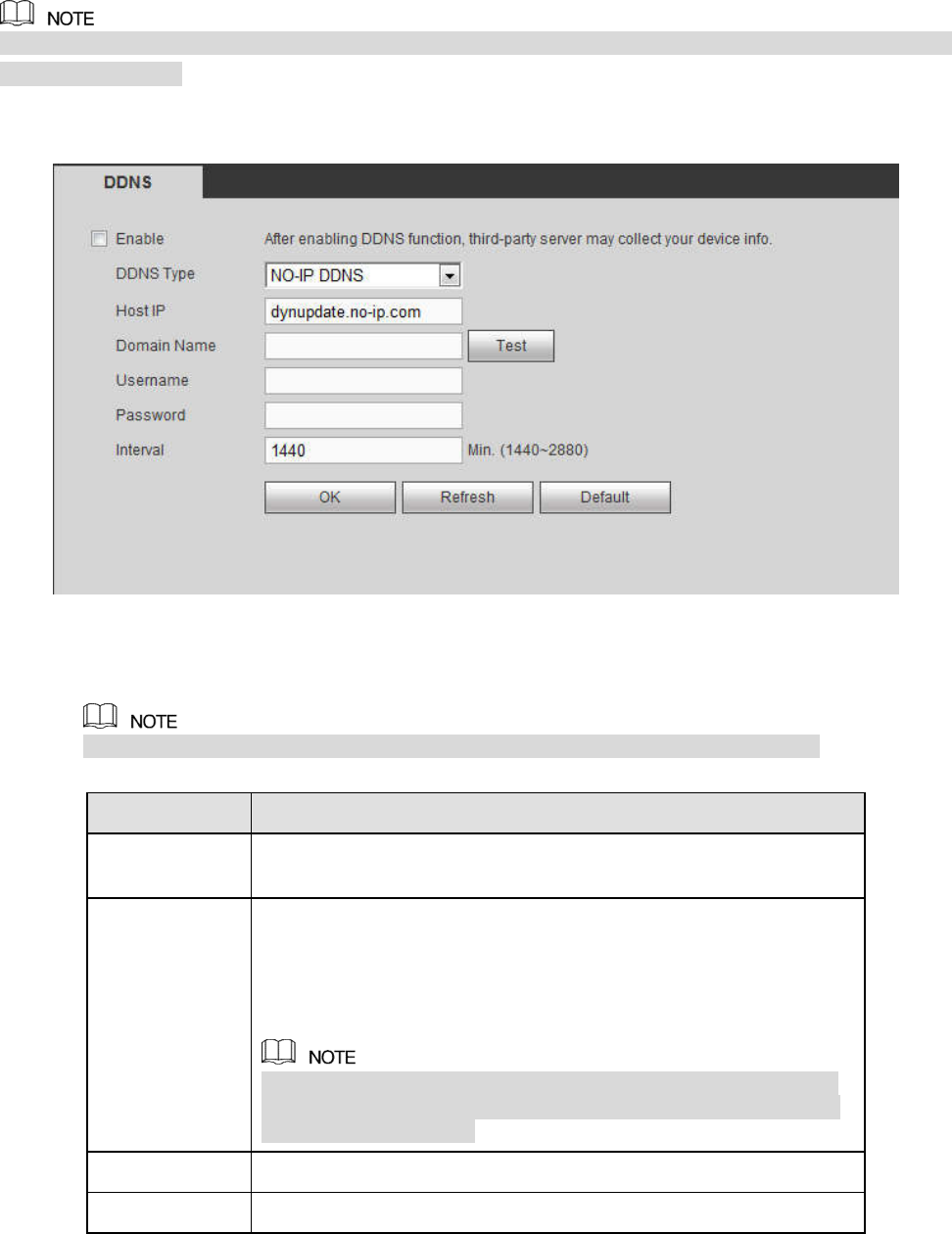
Step 1 Enter from main memu > Setup > Network > DDNS.
DDNS setup interface is shown as in Figure 5-41.
Figure 5-41
Step 2 Select the Enable check box.
After enabling DDNS, the third-party server might collect your device information.
Step 3 Select the DDNS type and configure the parameters. For details, see the below table.
Parameter Description
Server Type You can select DDNS protocol from the dropdown list and then
enable DDNS function.
Address DDNS server IP address list:
Dyndns DDNS: members.dyndns.org.
NO-IP DDNS: dynupdate.no-ip.com.
CN99 DDNS: members.3322.org.
When the DDNS type is NO-IP DDNS, some series will display
the Test button. Click Test and you can detect if the device has
registered successfully.
Domain Name
Your self-defined domain name.
User The user name you input to log in the server.
262
Parameter Description
Password The password you input to log in the server.
Test After the configuration, click Test and system saves the
configuration and check if the domain name can be registered
successfully.
If succeeded, go to step4.
If failed, check if the domain information is correct and clear
the browser buffer.
System supports this function when DDNS type is NO-IP DDNS.
Update period
The time interval to send update request. Unit: Minute.
Step 4 Click Save to complete the setting.
Step 5 Input the domain name in the Web browser and click Enter key. The setting is right if you can
view the Web interface of the device. Otherwise, check the parameters.
5.11.2.8 Email
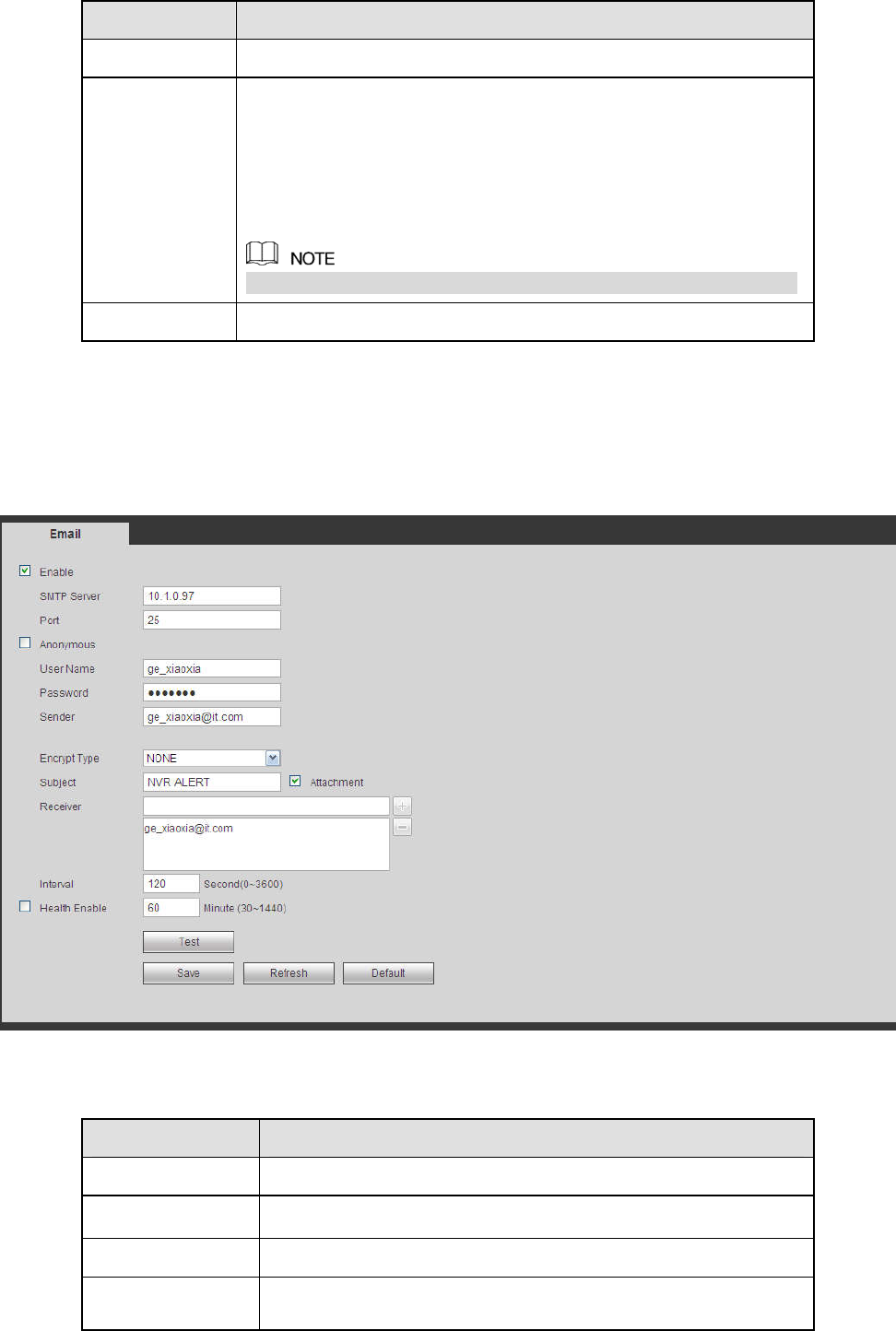
The email interface is shown as in Figure 5-42.
Figure 5-42
Please refer to the following sheet for detailed information.
Parameter Function
Enable Please check the box here to enable email function.
SMTP Server Input server address and then enable this function.
Port Default value is 25. You can modify it if necessary.
Anonymity For the server supports the anonymity function. You can auto
login anonymously. You do not need to input the user name.

263
Parameter Function
password and the sender information.
User Name The user name of the sender email account.
Password The password of sender email account.
Sender Sender email address.
Authentication
(Encryption
mode)
You can select SSL or none.
Subject Input email subject here.
Attachment System can send out the email of the snapshot picture once
you check the box here.
Receiver Input receiver email address here. Max three addresses.
It supports SSL, TLS email box.
Interval The send interval ranges from 0 to 3600 seconds. 0 means
there is no interval.
Please note system will not send out the email immediately
when the alarm occurs. When the alarm, motion detection or
the abnormity event activates the email, system sends out the
email according to the interval you specified here. This
function is very useful when there are too many emails
activated by the abnormity events, which may result in heavy
load for the email server.
Health mail
enable
Please check the box here to enable this function.
Update period
(interval)
This function allows the system to send out the test email to
check the connection is OK or not.
Please check the box to enable this function and then set the
corresponding interval. The value ranges from 30 minutes to
1440 minutes.
System can send out the email regularly as you set here.
Email test The system will automatically sent out a email once to test the
connection is OK or not .Before the email test, please save the
email setup information.
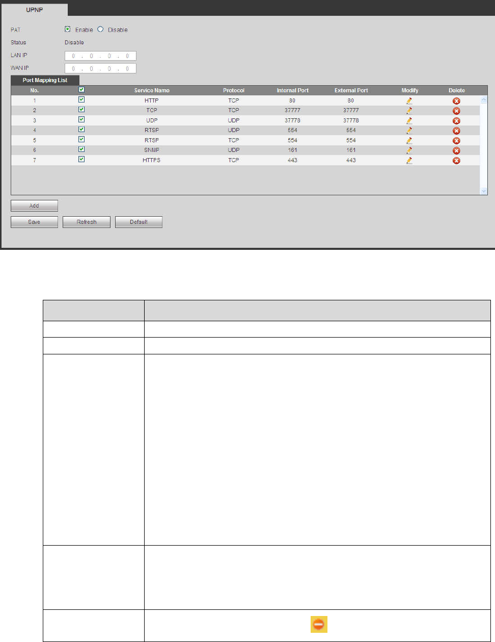
5.11.2.9 UPnP
It allows you to establish the mapping relationship between the LAN and the public network.
Here you can also add, modify or remove UPnP item. See Figure 5-43.
In the Windows OS, From Start->Control Panel->Add or remove programs. Click the “Add/Remove
Windows Components” and then select the “Network Services” from the Windows Components
Wizard.
Click the Details button and then check the “Internet Gateway Device Discovery and Control client”
and “UPnP User Interface”. Please click OK to begin installation.
Enable UPnP from the Web. If your UPnP is enabled in the Windows OS, the NVR can auto detect it
via the “My Network Places”
264
Figure 5-43
Please refer to the following sheet for detailed information.
Parameter Function
PAT Check the corresponding box to enable PAT function.
Status Display UPnP function status.
Port mapping list
It is corresponding to the UPnP mapping information on the router.
Check the box before the service name to enable current PAT service.
Otherwise, the service is null.
Service name: Customized name.
Protocol: Protocol type.
Internal port: The port mapped to the port.
External port: The port current device needs to map.
Device has three mapping items: HTTP/TCP/UDP.
Note
When you set the external port (outport) of the router, the value ranges
from 1024 to 5000. Do not use port 1~255 or system port 256~1023,
in case there is conflict.
Add
Click Add button to add map relationship.
Note
For the data transmission protocol TCP/UDP, the external port and the
internal port shall be the same to guarantee proper data transmission.
Delete Select one service and then click to delete map relationship.
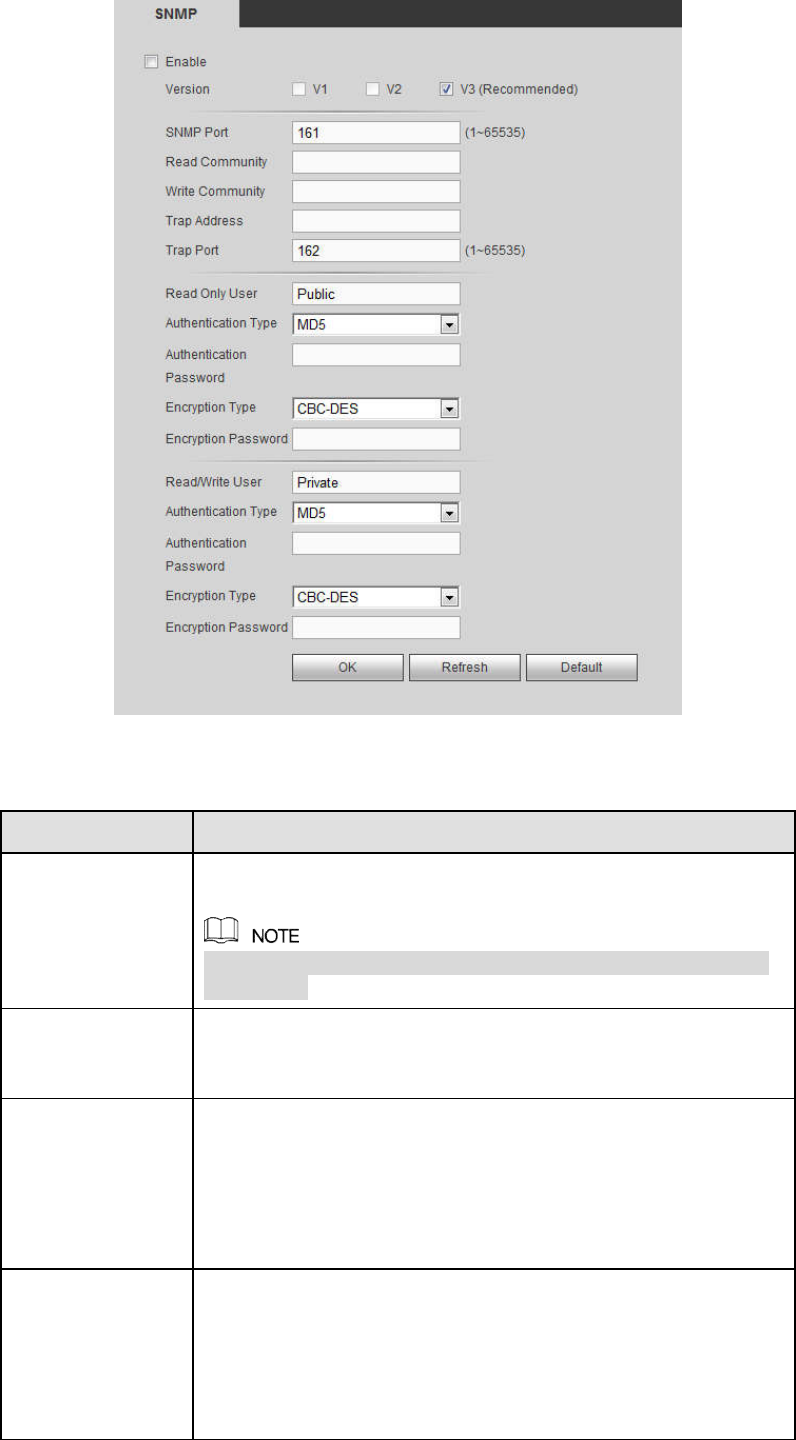
5.11.2.10 SNMP
The SNMP interface is shown as in Figure 5-44.
The SNMP allows the communication between the network management work station software and the
proxy of the managed device. It is reserved for the 3rd party to develop.
265
Figure 5-44
Please refer to the following sheet for detailed information.
Parameter Function
Version Select by clicking the check box in front of the corresponding
version.
System selects V3 by default. There might be some risks for
V1 and V2.
SNMP Port The listening port of the proxy program of the device. It is a
UDP port not a TCP port. The value ranges from 1 to 65535.
The default value is 161
Read Community
It is a string. It is a command between the manage process
and the proxy process. It defined the authentication, access
control and the management relationship between one proxy
and one group of the managers. Please make sure the device
and the proxy are the same.
The read community will read all the objects the SNMP
supported in the specified name. The default setup is public.
Write Community
It is a string. It is a command between the manage process
and the proxy process. It defined the authentication, access
control and the management relationship between one proxy
and one group of the managers. Please make sure the device
and the proxy are the same.
The read community will read/write/access all the objects the
SNMP supported in the specified name. The default setup is
266
Parameter Function
write.
Trap address The destination address of the Trap information from the proxy
program of the device.
Trap port The destination port of the Trap information from the proxy
program of the device. It is for the gateway device and the
client-end PC in the LAN to exchange the information. It is a
non-protocol connection port. It has no effect on the network
applications. It is a UDP port not TCP port. The value ranges
from 1 to 165535. The default value is 162.
Read-only user It only supports reading function when logging in the device
with this user account.
Authentication
mode
Including two modes: MD5 and SHA. The system can
automatically recognize it after enabled.
Read-write user It supports reading and writing when logging in the device with
this user account.
Password The password for authentication and encryption. It shall be no
less than 8 characters.
Encryption Type Select the encryption mode. The default mode is CBC-DES.
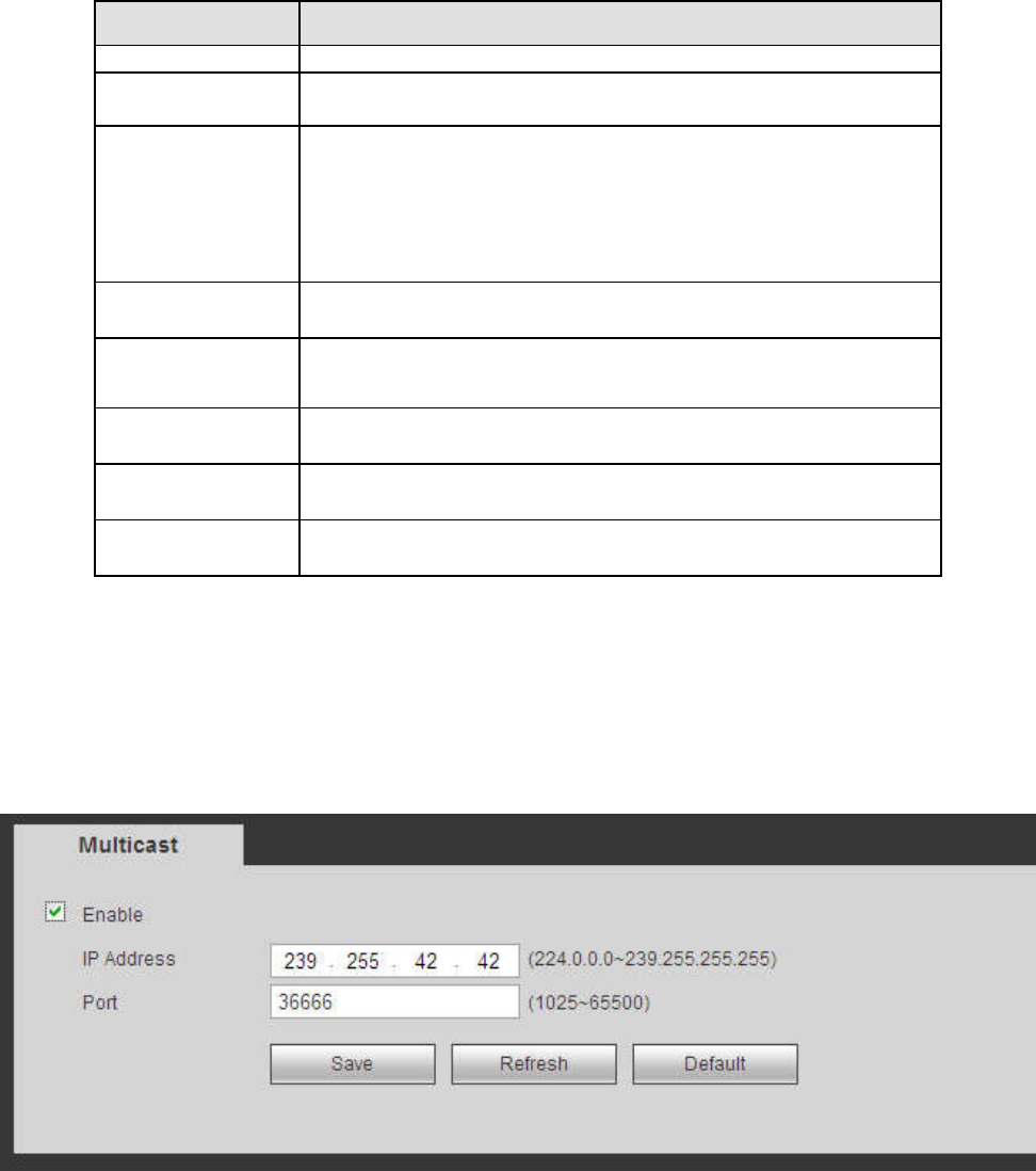
5.11.2.11 Multicast
The multicast interface is shown as in Figure 5-45.
Multicast is a transmission mode of data packet. When there is multiple-host to receive the same data
packet, multiple-cast is the best option to reduce the broad width and the CPU load. The source host
can just send out one data to transit. This function also depends on the relationship of the group member
and group of the outer.
Figure 5-45
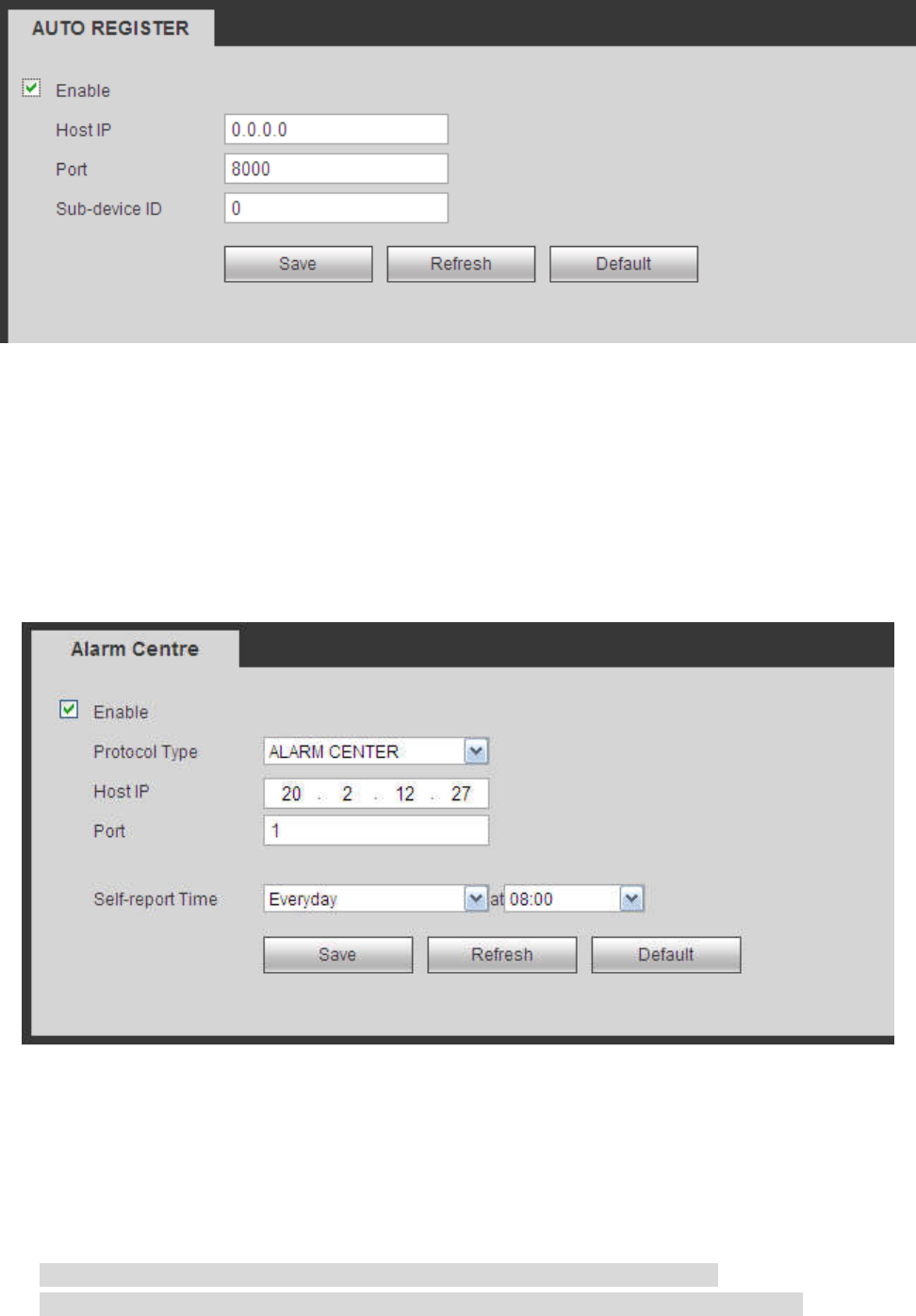
5.11.2.12 Auto Register
The auto register interface is shown as below. See Figure 5-46.
This function allows the device to auto register to the proxy you specified. In this way, you can use the
client-end to access the NVR and etc via the proxy. Here the proxy has a switch function. In the network
service, device supports the server address of IPv4 or domain.
Please follow the steps listed below to use this function.
Please set proxy server address, port, and sub-device name at the device-end. Please enable the auto
register function, the device can auto register to the proxy server.
267
Figure 5-46
5.11.2.13 Alarm Centre
The alarm center interface is shown as below. See Figure 5-47.
This interface is reserved for you to develop. System can upload alarm signal to the alarm center when
local alarm occurs.
Before you use alarm center, please set server IP, port and etc. When an alarm occurs, system can send
out data as the protocol defined, so the client-end can get the data.
Figure 5-47
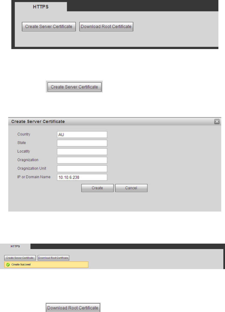
5.11.2.14 HTTPS
In this interface, you can set to make sure the PC can successfully login via the HTTPS. It is to guarantee
data communication security. The reliable and stable technology can secure the user information security
and device safety. See Figure 5-48.
Note
You need to implement server certificate again if you have changed device IP.
You need to download root certificate if it is your first time to use HTTPS on current PC.
268
Figure 5-48
5.11.2.14.1 Create Server Certificate
If it is your first time to use this function, please follow the steps listed below.
In Figure 5-48, click button, input country name, state name and etc. Click
Create button. See Figure 5-49.
Note
Please make sure the IP or domain information is the same as your device IP or domain name.
Figure 5-49
You can see the corresponding prompt. See Figure 5-50. Now the server certificate is successfully
created.
Figure 5-50
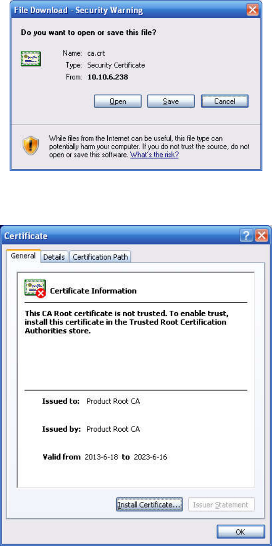
5.11.2.14.2 Download root certificate
In Figure 5-48, click button, system pops up a dialogue box. See Figure 5-51.
269
Figure 5-51
Click Open button, you can go to the following interface. See Figure 5-52.
Figure 5-52
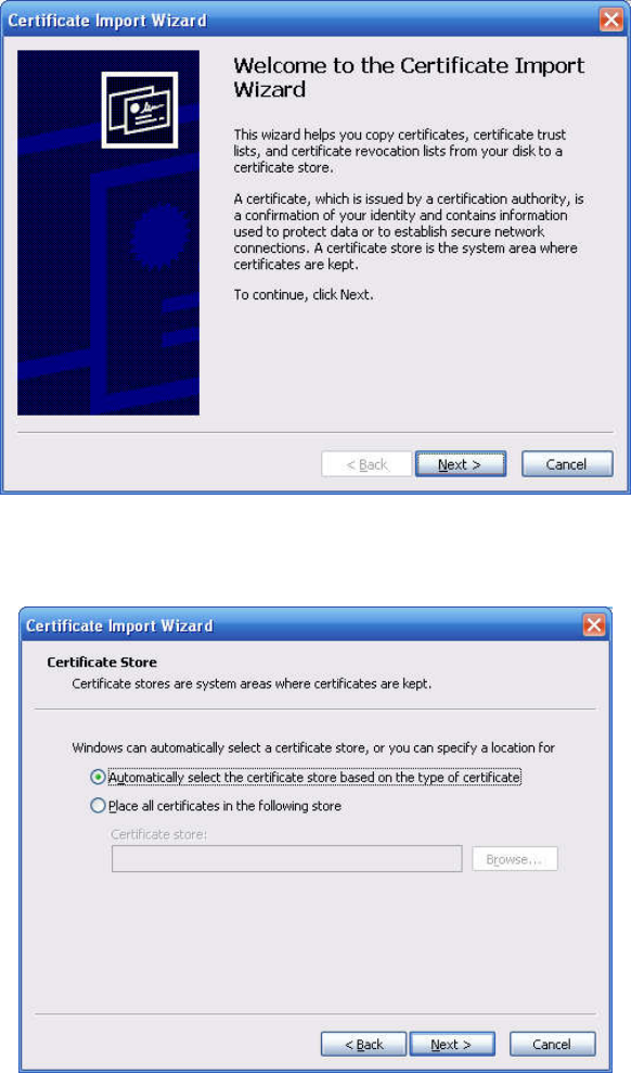
Click Install certificate button, you can go to certificate wizard. See Figure 5-53.
270
Figure 5-53
Click Next button to continue. Now you can select a location for the certificate. See Figure 5-54.
Figure 5-54
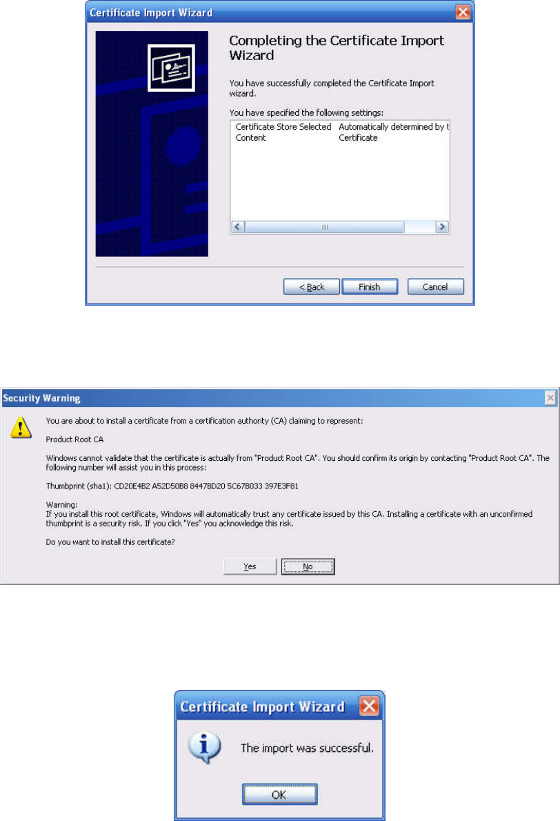
Click Next button, you can see the certificate import process is complete. See Figure 5-55.
271
Figure 5-55
Click Finish button, you can see system pops up a security warning dialogue box. See Figure 5-56.
Figure 5-56
Click Yes button, system pops up the following dialogue box, you can see the certificate download is
complete. See Figure 5-57.
Figure 5-57
5.11.2.14.3 View and set HTTPS port
From Setup->Network->Port, you can see the following interface. See Figure 5-58.
You can see HTTPS default value is 443.
272
Figure 5-58
5.11.2.14.4 Login
Open the browser and then input https://xx.xx.xx.xx:port.
xx.xx.xx.xx: is your device IP or domain mane.
Port is your HTTPS port. If you are using default HTTPS value 443, you do not need to add port
information here. You can input https://xx.xx.xx.xx to access.
Now you can see the login interface if your setup is right.
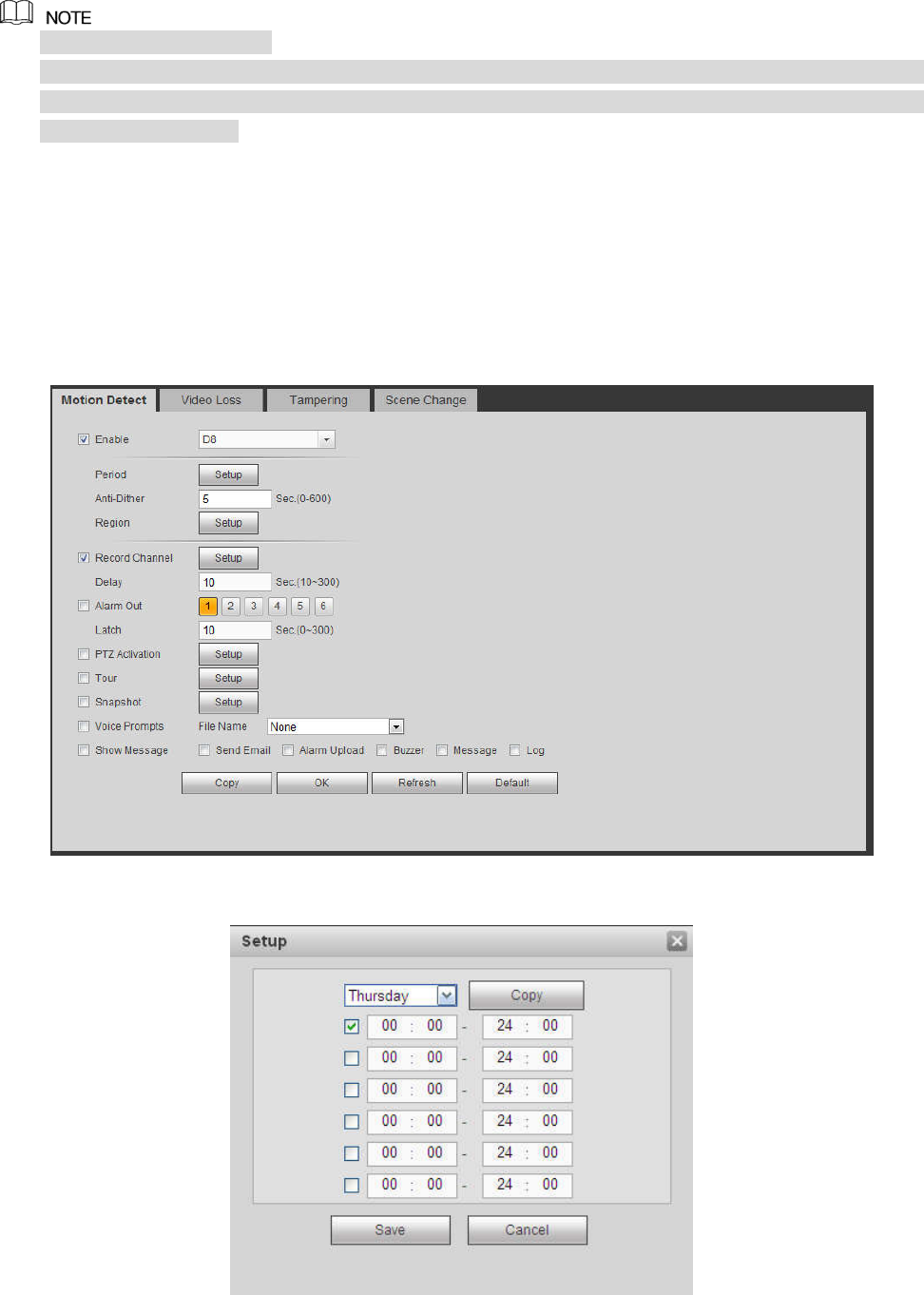
5.11.2.15 P2P
You can use your cell phone to scan the QR code and add it to the cell phone client.
Via the SN from scanning the QR code, you can access the device in the WAN. Please refer to the P2P
operation manual included in the resources CD.
The P2P interface is shown as in Figure 5-59.
Figure 5-59
273
Check the Enable box to enable P2P function and then click the Save button. When the Status shows
Online, the P2P registration is successful.
P2P is enabled by default.
To enable you to manage the device on the mobile APP, we will collect device information like IP
address, MAC address, device name and device SN. The collected information is only used for
remote device access.
5.11.3 Event
5.11.3.1 Video detect
5.11.3.1.1 Motion Detect
After analysis video, system can generate a video loss alarm when the detected moving signal reached
the sensitivity you set here.
The motion detect interface is shown as in Figure 5-60.
Figure 5-60
274
Figure 5-61
Figure 5-62
Figure 5-63
275
Figure 5-64
Figure 5-65
Please refer to the following sheet for detailed information.
Parameter Function
Enable You need to check the box to enable motion detection function.
Please select a channel from the dropdown list.
Period Motion detection function becomes activated in the specified
periods. See Figure 5-61.
There are six periods in one day. Please draw a circle to enable
corresponding period.
Click OK button, system goes back to motion detection interface,
please click save button to exit.
Anti-dither System only memorizes one event during the anti-dither period.
The value ranges from 5s to 600s.
Sensitivity There are six levels. The sixth level has the highest sensitivity.
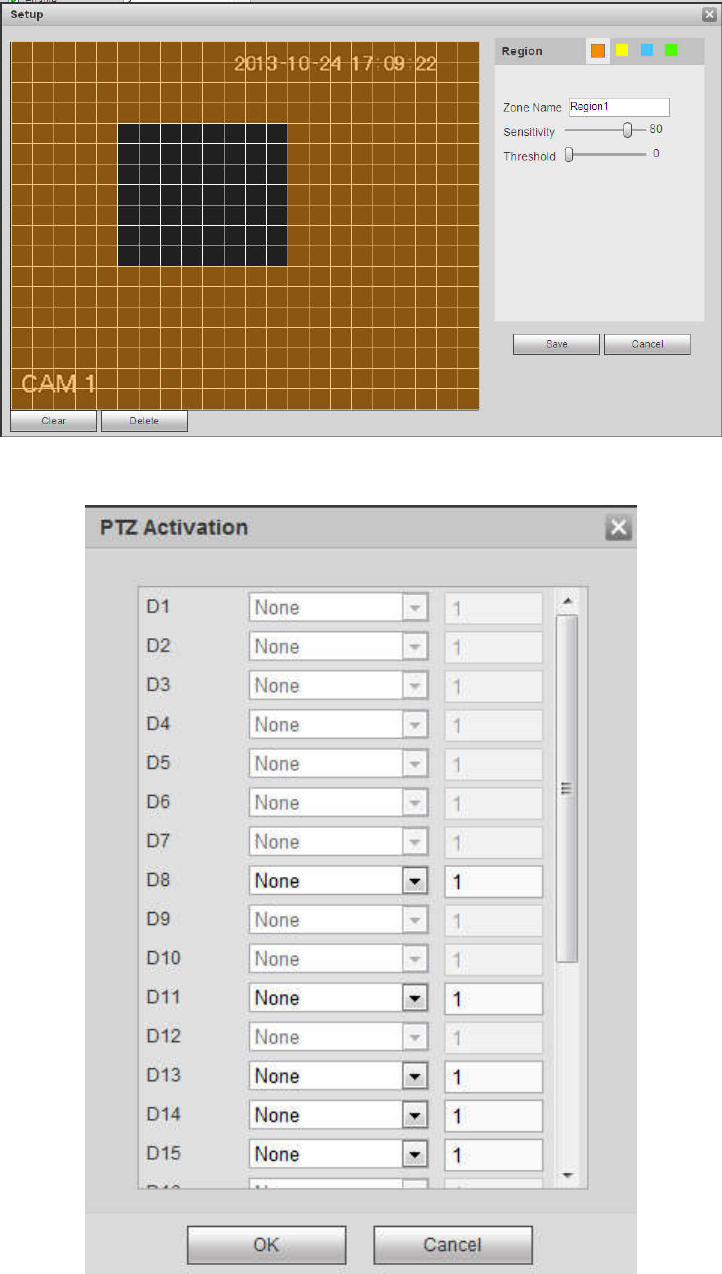
Region If you select motion detection type, you can click this button to set
motion detection zone. The interface is shown as in Figure 5-62.
Here you can set motion detection zone. There are four zones for
you to set. Please select a zone first and then left drag the mouse
to select a zone. The corresponding color zone displays different
detection zone. You can click Fn button to switch between the arm
mode and disarm mode. In arm mode, you can click the direction
buttons to move the green rectangle to set the motion detection
zone. After you completed the setup, please click ENTER button to
exit current setup. Do remember click save button to save current

276
Parameter Function
setup. If you click ESC button to exit the region setup interface
system will not save your zone setup.
Record
channel System auto activates motion detection channel(s) to record once
an alarm occurs. Please note you need to set motion detect record
period and go to Storage-> Schedule to set current channel as
schedule record.
Record Delay
System can delay the record for specified time after alarm ended.
The value ranges from 10s to 300s.
Alarm out Enable alarm activation function. You need to select alarm output
port so that system can activate corresponding alarm device when
an alarm occurs.
Latch System can delay the alarm output for specified time after an
alarm ended. The value ranges from 1s to 300s.
Show
message System can pop up a message to alarm you in the local host
screen if you enabled this function.
Buzzer Check the box here to enable this function. The buzzer beeps
when an alarm occurs.
Alarm upload
System can upload the alarm signal to the center (Including alarm
center.
Message When 3G network connection is OK, system can send out a
message when motion detect occurs.
Send Email If you enabled this function, System can send out an email to alert
you when an alarm occurs.
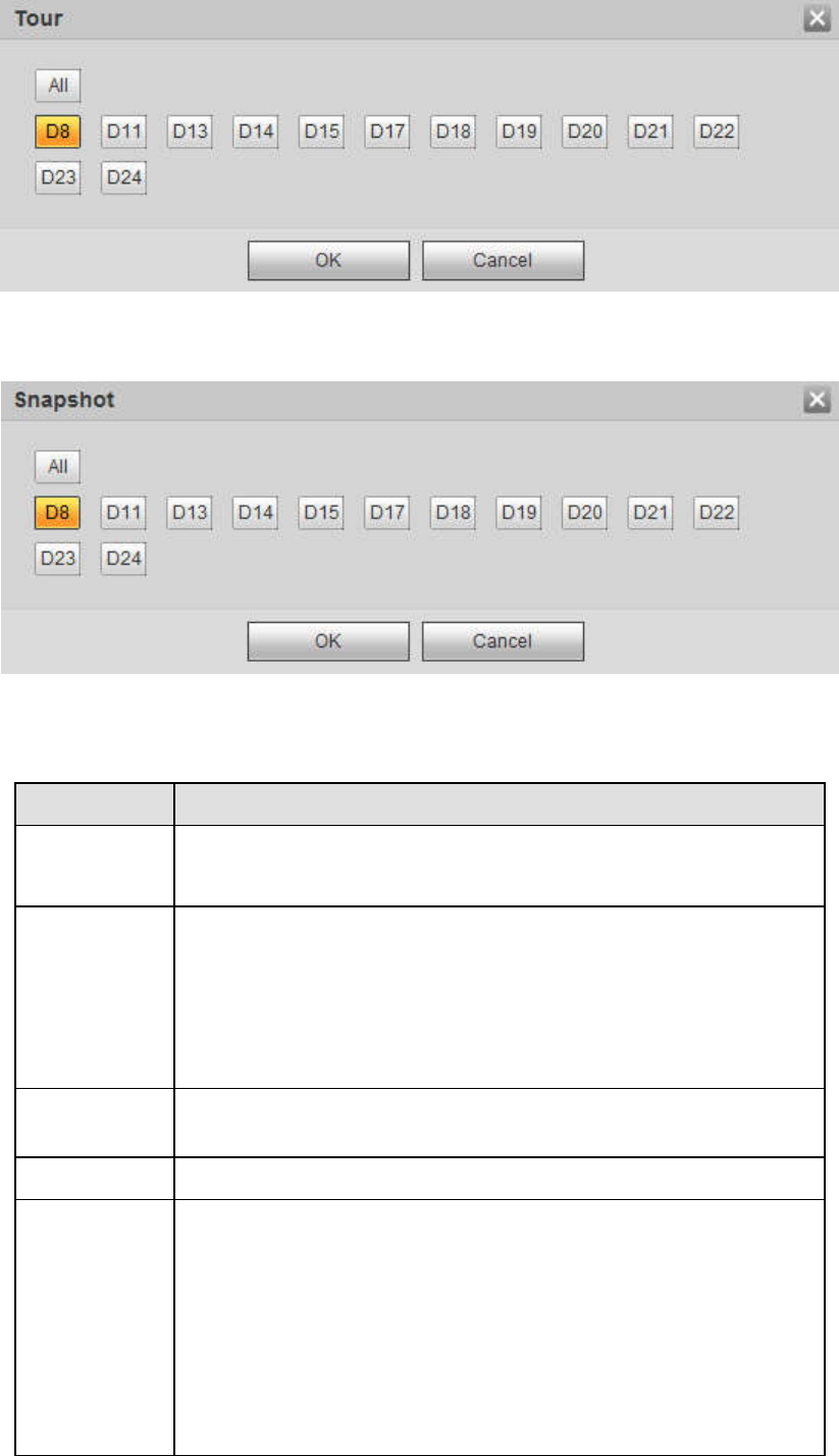
Tour You need to click setup button to select tour channel. System
begins 1-wiindow or multiple-window tour display among the
channel(s) you set to record when an alarm occurs. See Figure
5-64.
PTZ
Activation Here you can set PTZ movement when alarm occurs. Such as go
to preset X. See Figure 5-63.
Snapshot Click setup button to select snapshot channel. See Figure 5-65.
Video Matrix
This function is for motion detect only. Check the box here to
enable video matrix function. Right now system supports
one-channel tour function. System takes “first come and first
serve” principle to deal with the activated tour. System will process
the new tour when a new alarm occurs after previous alarm ended.
Otherwise it restores the previous output status before the alarm
activation.
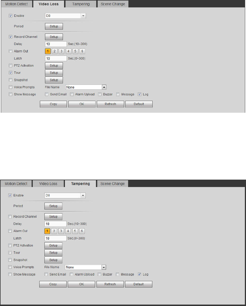
5.11.3.1.2 Video Loss
The video loss interface is shown as in Figure 5-66.
Please note video loss does not support anti-dither, sensitivity, region setup. For rest setups, please refer
to chapter 5.11.3.1.1 motion detect for detailed information.
277
Figure 5-66
5.11.3.1.3 Tampering
The tampering interface is shown as in Figure 5-67.
After analysis video, system can generate a tampering alarm when the detected moving signal reached
the sensitivity you set here.
For detailed setups, please refer to chapter 5.11.3.1.1 motion detect for detailed information.
Figure 5-67
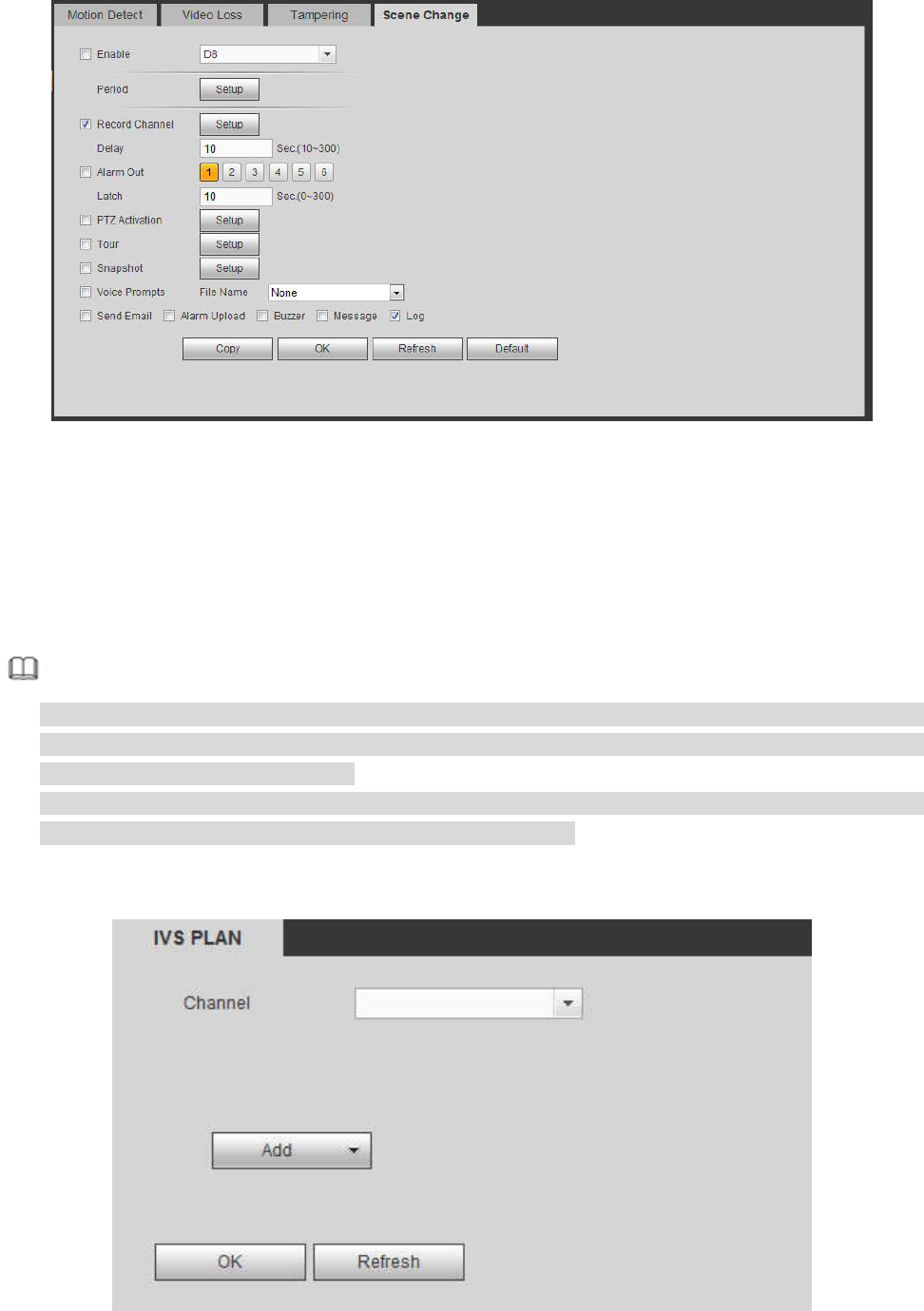
5.11.3.1.4 Scene Change
From main window->Setup->Event->Video detect->Scene change, the video diagnosis interface is shown
as in Figure 5-68.
278
Figure 5-68
For detailed setups, please refer to chapter 5.11.3.1.1 motion detect for detailed information.
5.11.3.2 IVS Plan
The smart plan is for the smart network camera. If you do not set a rule here, you cannot use the
intelligent functions in IVS (Chapter 5.11.3.3), Face detection (Chapter 5.11.3.4) and People counting
(Chapter 5.11.3.5) when you are connecting to a smart network camera.
There are two types to realize intelligent analytics function.
Note
Smart network camera supports intelligent functions: Some smart camera supports the intelligent
functions. For NVR, it just displays the intelligent alarm information from the smart network camera
and set or playback the record file.
NVR supports intelligent functions: The connected network camera does not support intelligent video
analytics function. The NVR supports the analytics function.
From main menu->Setup->Event->IVS plan, you can go to the IVS plan interface. See Figure 5-69.
Figure 5-69
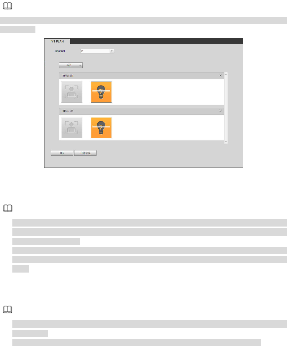
279
Select a channel from the dropdown list. Click Add button, you can see an interface shown as below. See
Figure 5-70.
Select a channel from the dropdown list and then set preset. Click Add button and then set the
corresponding rule.
Note
Some smart camera does not need to add the preset. Please refer to the actual product for detailed
information.
Figure 5-70
Click OK button to complete the setup.
Note
The NVR supports general behavior analytics (IVS), human face detection, heat map, and people
counting. Different network camera supports different smart plans. Please refer to the actual product
for detailed information.
The general behavior analytics (IVS) and human face detection function cannot be valid at the same
time. For example, when add the IVS plan to the preset 1, the human face detection icon becomes
grey.
5.11.3.3 IVS (Behavior Analytics) (Optional)
Once the object state has reached the threshold, NVR can trigger an intelligent alarm.
Note
This function is for some series product only. Please refer to the actual product for detailed
information.
The IVS function and the human face detection function cannot be valid at the same time.
The IVS function environment shall meet the following requirements:
The object total size shall not be more than 10% of the whole video.
The object size on the video shall not be more than 10pixels*10 pixels. The abandoned object size
shall be more than 15pixels*15 pixels (CIF resolution). The object width shall not be more than 1/3 of
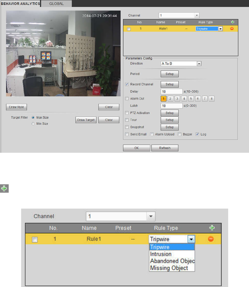
280
the video height and width. The recommended height is 10% of the video.
The object and the background brightness different shall be more than 10 grey levels.
The object shall remain on the video for more than 2 seconds. The moving distance is larger than its
own width and shall not be smaller than 15pixels (CIF resolution).
The surveillance environment shall not be too complicated. The IVS function is not suitable for the
environment of too many objects or the changing light.
The surveillance environment shall not contain glasses, reflection light from the ground, and water.
Free of tree branches, shadow, mosquito and bugs. Do not use the IVS function in the backlight
environment, avoid direct sunlight.
5.11.3.3.1 Behavior Analytics
From main menu->Setup->Event->Behavior analytics->Behavior analytics, you can go to the Behavior
analytics interface. See Figure 5-71.
Figure 5-71
Please select a channel from the dropdown list
Click to add a rule. The default setup is tripwire, you can double click the rule type name to modify.
See Figure 5-72.
Figure 5-72
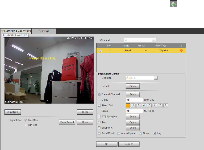
281
Then you can set corresponding parameters.
Click OK button to complete the setup.
5.11.3.3.2 Tripwire
From main menu->Setup->Event-> Behavior analytics->Behavior analytics, click you can see the
following interface. See Figure 5-73.
System generates an alarm once there is any object crossing the tripwire in the specified direction.
Figure 5-73
Check the Tripwire box to enable tripwire function.
Select SN (Line1/2/3/4) and direction, and then input customized rule name.
Direction: There are three options: A->B, B->A, both. System can generate an alarm once there is
any object crossing in the specified direction.
Now you can draw a rule. Click Draw rule button and then left click mouse to draw a tripwire. The tripwire
can be a direct line, curve or polygon. Right click mouse to complete. See Figure 5-74.
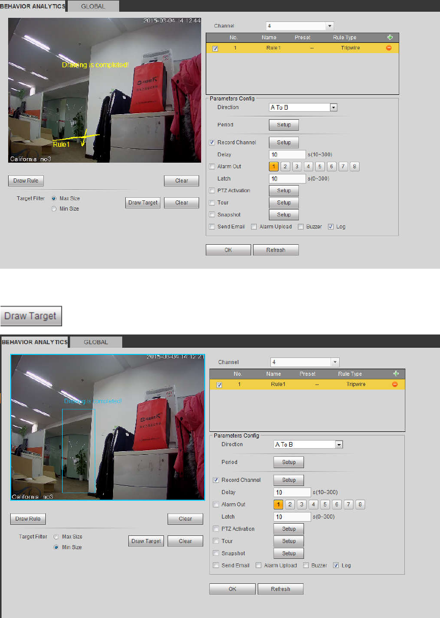
282
Figure 5-74
Click to draw filter object. See Figure 5-75.
Figure 5-75
Select the blue line and then use mouse to adjust zone size.
Note
Each rule can set two sizes (min size/max size). Once the object is smaller than the min size or larger
than the max size, there is no alarm. Please make sure the max size is larger than the min size.
Click Ok to complete the rule setup.
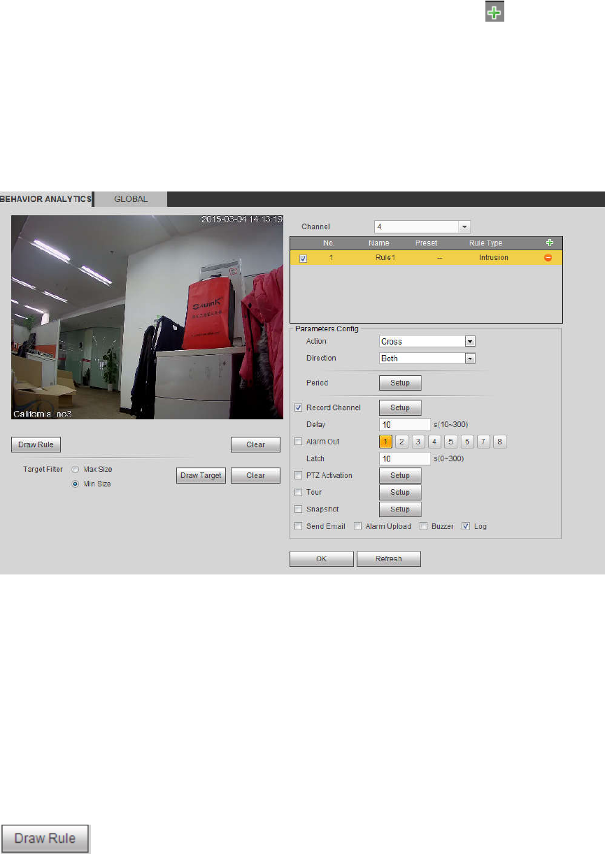
283
For detailed setups, please refer to chapter 5.11.3.1.1 motion detect for detailed information.
5.11.3.3.3 Intrusion (Cross warning zone)
From main menu->Setup->Event-> Behavior analytics->Behavior analytics, click , and then select rule
type as intrusion, you can see the following interface. See Figure 4-126.
Note:
System supports customized area shape and amount.
Support enter/leave/both detection.
Can detect the moving object operation in the specified zone, customized trigger amount and staying
time.
Support objects filter function.
Figure 5-76
Check the Intrusion box to enable intrusion function.
Select SN (Area1/2/3/4) and direction, and then input customized rule name.
Action: System supports two types: appear/cross.
Direction: There are three options: A->B, B->A, both. System can generate an alarm once there is
any object enter/exit (Or both) the zone.
Now you can draw a rule. Left click mouse to draw a line first and then right click mouse to draw another
line until you draw a rectangle, you can right click mouse to exit.
Click Ok to complete the rule setup.
Click to draw the zone. See Figure 5-77.
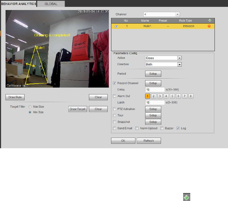
284
Figure 5-77
For detailed setups, please refer to chapter 5.11.3.1.1 motion detect for detailed information.
5.11.3.3.4 Abandoned Object Detect
From main menu->Setup->Event-> Behavior analytics->Behavior analytics, click , and then select rule
type as abandoned object detection, you can see the following interface. See Figure 5-78.
System supports customized area shape and amount.
Support duration setup.
Support objects filter function.
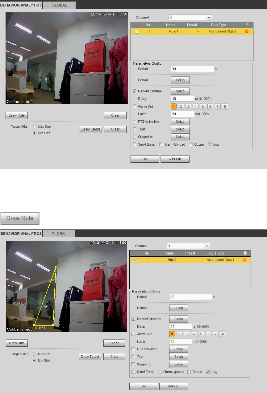
285
Figure 5-78
Check the Object box to enable object detect function.
Period: System can generate an alarm once the object is in the zone for the specified period.
Click to draw the rule. See Figure 5-79.
Figure 5-79
Now you can draw a rule. Left click mouse to draw a line, until you draw a rectangle, you can right click
mouse.
Click Ok to complete the rule setup.
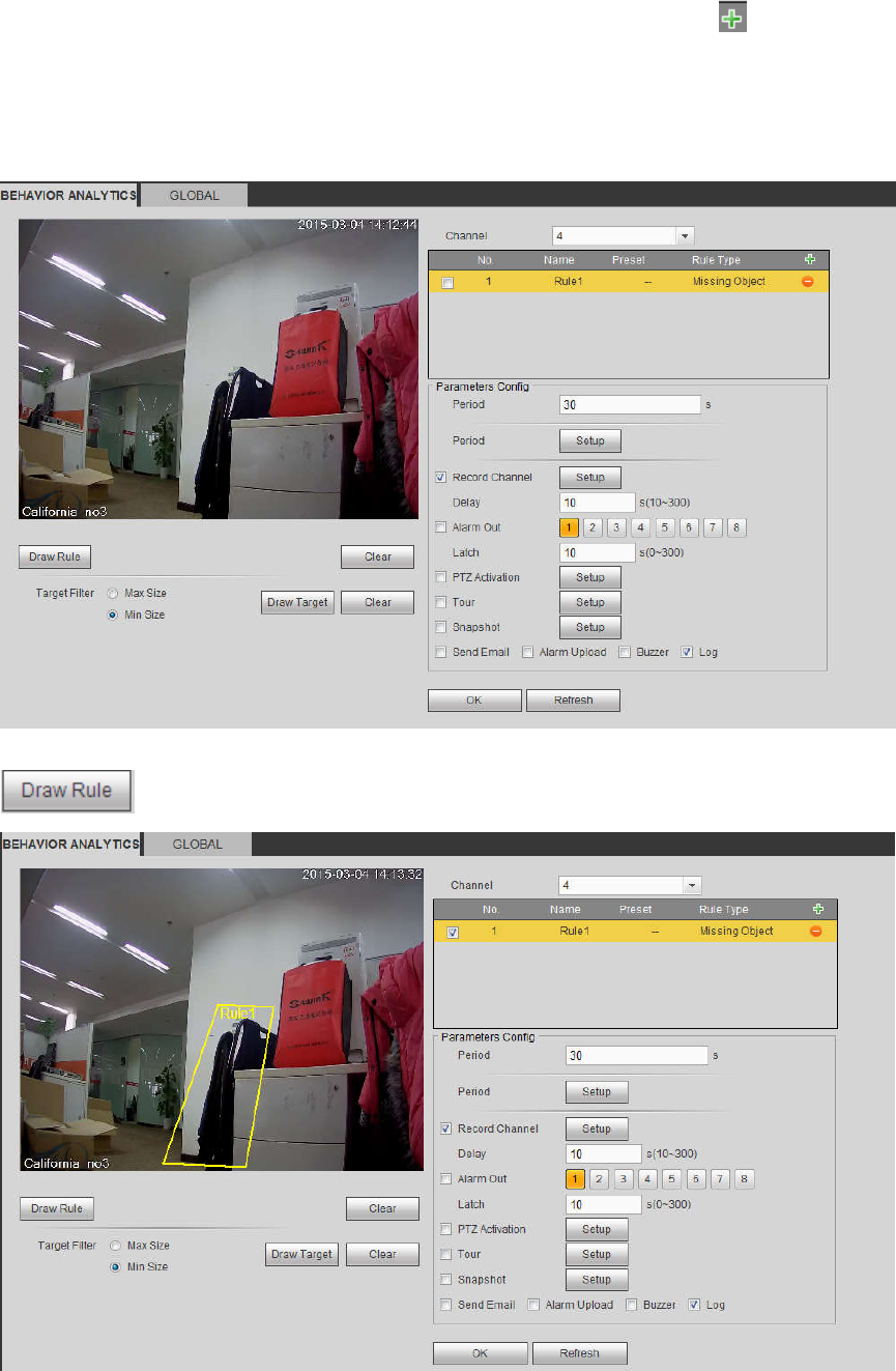
286
For detailed setups, please refer to chapter 5.11.3.1.1 motion detect for detailed information.
5.11.3.3.5 Missing Object Detect
From main menu->Setup->Event-> Behavior analytics->Behavior analytics, click , and then select rule
type as missing object detection, you can see the following interface. See 错误!未找到引用源。.
System supports customized area shape and amount.
Support period setup.
Support objects filter function.
Figure 5-80
Click to draw the rule. See Figure 5-81.
Figure 5-81
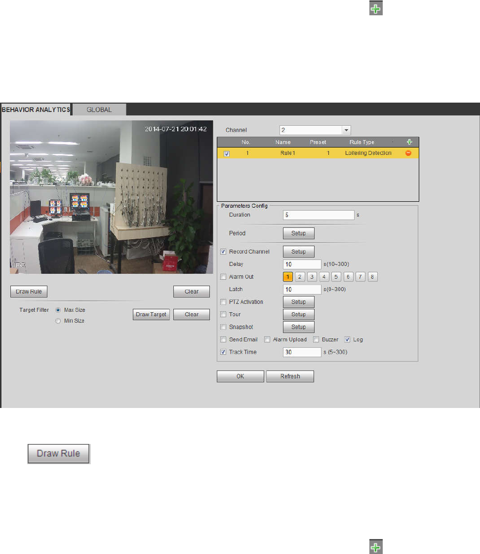
287
Click Ok to complete the rule setup.
For detailed setups, please refer to chapter 5.11.3.1.1 motion detect for detailed information.
5.11.3.3.6 Loitering
From main menu->Setup->Event-> Behavior analytics->Behavior analytics, click , and then select rule
type as loitering detection, you can see the following interface. See 错误!未找到引用源。.
Note
System supports customized area shape and amount.
Support duration setup.
Support objects filter function.
Figure 5-82
Duration: System can generate an alarm once the object is in the zone for the specified period.
Click to draw the rule.
Click OK to complete the rule setup.
For detailed setups, please refer to chapter 5.11.3.1.1 motion detect for detailed information.
5.11.3.3.7 Crowd gathering detection
From main menu->Setup->Event-> Behavior analytics->Behavior analytics, click , and then select rule
type as crowd gathering estimation, you can see the following interface. See 错误!未找到引用源。.
Customized zone and amount setup.
Duration setup.
Sensitivity setup.
Min gathering zone setup.
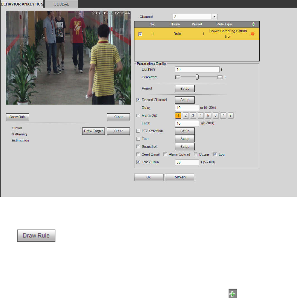
288
Figure 5-83
Duration: System can generate an alarm once the object is in the zone for the specified period.
Sensitivity: It is to set alarm sensitivity. The value ranges from 1 to 10.The default setup is 5.
Click to draw the rule.
Click OK to complete the rule setup.
For detailed setups, please refer to chapter 5.11.3.1.1 motion detect for detailed information.
5.11.3.3.8 Fast moving
From main menu->Setup->Event-> Behavior analytics->Behavior analytics, click , and then select rule
type as fast moving, you can see the following interface. See 错误!未找到引用源。.
Sensitivity: It is to set alarm sensitivity. The value ranges from 1 to 10.The default setup is 5.
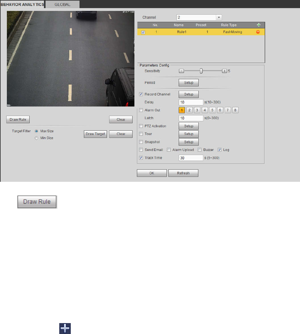
289
Figure 5-84
Click to draw the rule.
Click OK to complete the rule setup.
For detailed setups, please refer to chapter 5.11.3.1.1 motion detect for detailed information.
5.11.3.3.9 Global Config
From main menu->Setup->Event->Behavior analytics->Global, you can go to the global configuration
interface. See the below figure.
Channel: Please select a channel from the dropdown list.
Preset: Select a preset you want to set the rule. Please note, you need to add a preset first,
otherwise, you cannot see the preset dropdown list. If there is no preset, you can draw a rule in
current channel.
Calibration zone:
Click Add area , you can draw a calibration zone at the left pane of the interface. Select a zone
and then click Delete zone button; you can remove the selected zone.
Select gauge type (vertical/level), you can set the corresponding length. You can draw three tilt
gauges and one horizontal gauge at the left pane of the interface.
Select Width/Height and then click Verify, you can draw a line in the calibration zone, and then you
can see its actual length.
Update preset: Click it to get the latest preset setup.
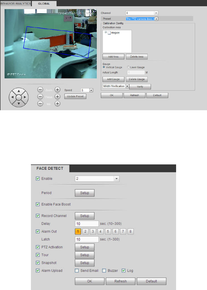
290
Figure 5-85
5.11.3.4 Face Detect (Optional)
When camera detects human face, system can generate an alarm.
From main menu->Setup->Event->Face detect, the interface is shown as in Figure 5-86.
Enable face boost: Check the box here, system can enhance the human face display pane.
Sensitivity: System supports 6 levels. The sixth level has the highest sensitivity.
Figure 5-86
For detailed setups, please refer to chapter 5.11.3.1.1.
5.11.3.5 People Counting
System can calculate the entry/exit people amount in the specified zone. It can generate an alarm when
the amount has exceeded the threshold.
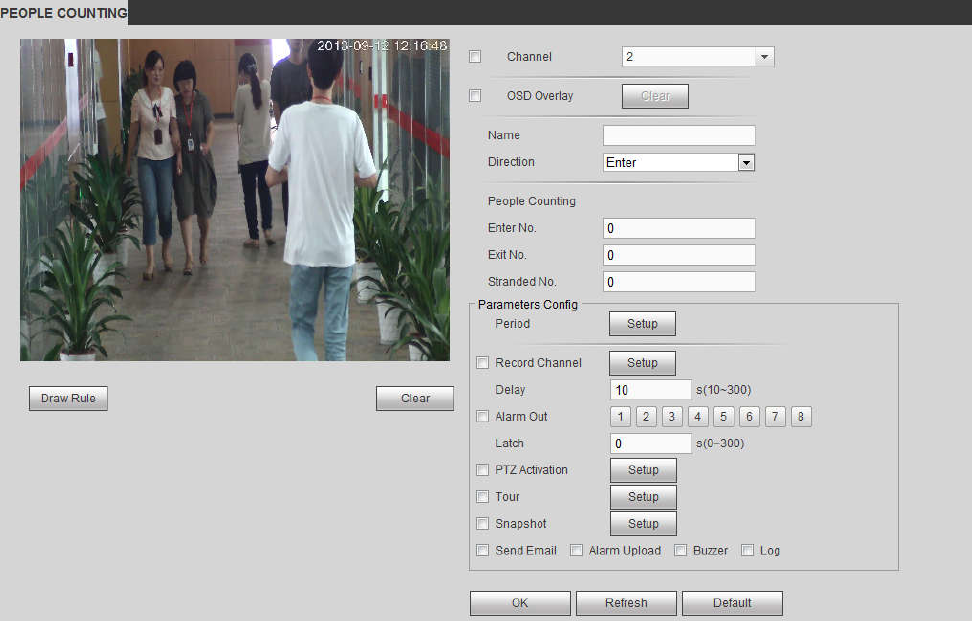
291
From main menu->Setup->Event->People counting, you can see an interface shown as the below figure.
Channel: Please select a channel from the dropdown list. Check the box to enable people counting
function.
OSD overlay: Check the box here; you can view the people amount on the surveillance video.
Direction: It is to set people flow direction. It includes entry/exit.
Entry No.: It is to set people entry amount. System can generate an alarm once the amount has
exceeded the threshold.
Exit No.: It is to set people entry amount. System can generate an alarm once the amount has
exceeded the threshold.
Stranded No.: It is to set people staying amount in the zone. System can generate an alarm once the
amount has exceeded the threshold.
For detailed setups, please refer to chapter 5.11.3.1.1 motion detect for detailed information.
Figure 5-87
5.11.3.6 Heat Map
It is to detect the object activity level in the scene during the specified period.
From main menu->Setup->Event->Heat Map, you can see an interface shown as in Figure 5-88.
For detailed setups, please refer to chapter 5.11.3.1.1 motion detect for detailed information.