Zhejiang Dahua Vision Technology DHNVR21W Network Video Recorder User Manual 4
Zhejiang Dahua Vision Technology Co., Ltd Network Video Recorder 4
Contents
- 1. User Manual -1
- 2. User Manual -2
- 3. User Manual -3
- 4. User Manual -4
User Manual -4
292
Figure 5-88
5.11.3.7 Plate Recognition
License plate recognition adopts video image recognition technology to extract the license plate number
in video image and match it with the pre-set license plate number. After successful matching, the system
performs alarm linkage action
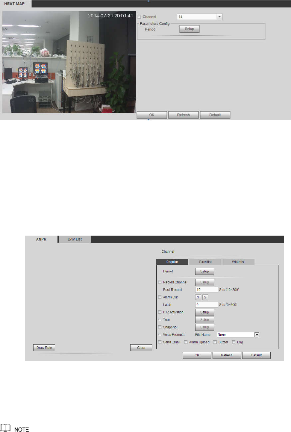
5.11.3.7.1 Configuring Plate Recognition
You can set the different plate recognition detection rules and alarm linkage actions under different
confitions (B/W list and regular)
Step 1 Select Setup > Event > ANPR.
The ANPR interface is displayed. See Figure 5-89.
Figure 5-89
Step 2 Select the Enable check box and choose the channel.
Step 3 Enter the Name and click Draw Rule to draw the rule region on the monitor screen.
Click Clear to cancel the drawing.
Step 4 Click the Regular, Whitelist or Blacklist tab according to actual needs. System displays the
Regular tab by default.
293
You need to configure the B/W list before using the B/W alarm linkage. For details, see 4.7.7.2 B/W List.
Regular: System activates alarm when any car plate is detected.
Blacklist: System activates alarm only when plates in the black list is detected.
Whitelist: System activates alarm only when plates in the white list is detected.
Step 5 Configure the parameters.
Step 6 Click OK to save the configuration.
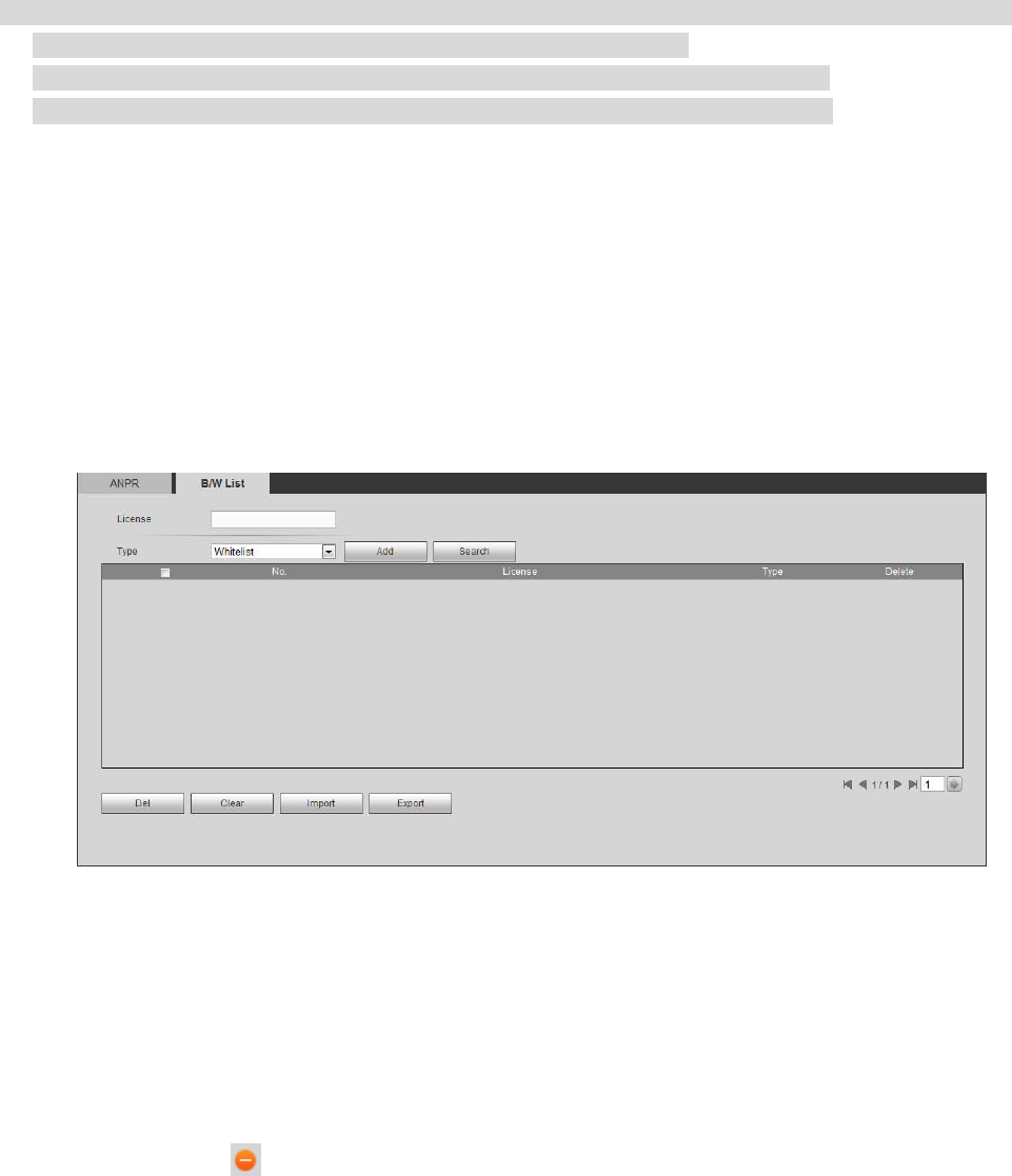
5.11.3.7.2 B/W List
It is to set the blacklist and the whitelist. It includes adding, deleting, importing and exporting blacklist and
whitelist.
After setting the blacklist and whitelist, in the plate snapshot list on the preview interface, the blacklist
plate number is red, the whitelist plate number is green and the regular plate number is white.
Adding B/W List
Step 1 Select Setup > Event > ANPR > B/W List.
The B/W list is diaplayed. See Figure 5-90.
Figure 5-90
Step 2 Enter the plate number and selecy whitelist or blacklist in the drop-down list.
Step 3 Click Add to complete the registration.
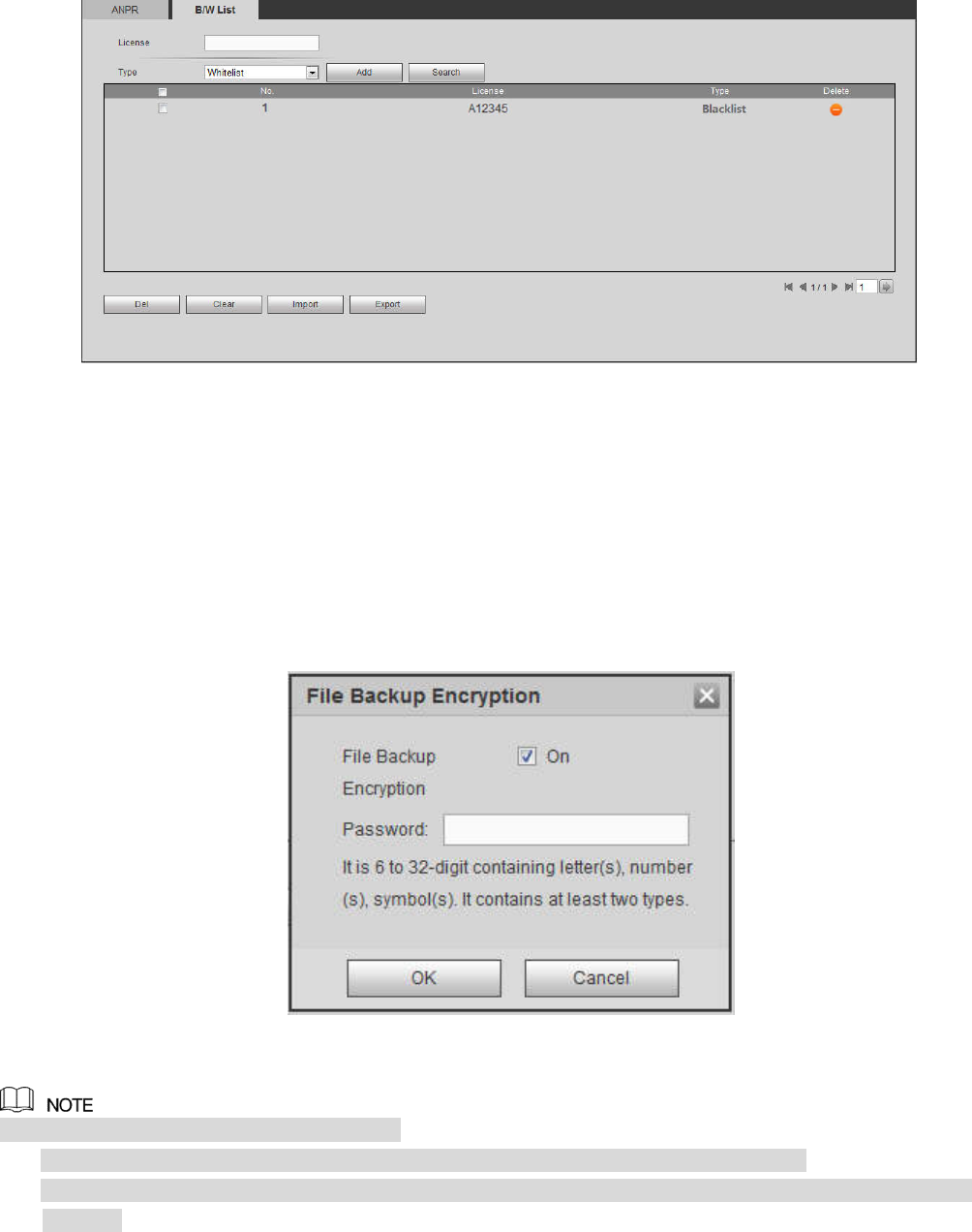
Deleting B/W List
In the Type list, select whitelist, blacklist or all and click Search, system displays the detailed information.
See Figure 5-91.
Select the check box in front of the plate number and click Delete to delete the plate info in the list.
You can also click corresponding to the plate number to delete it.
Click Clear to delete all the information in the B/W list.
294
Figure 5-91
Importing /Exporting B/W List
System supports to import B/W list from the peripheral USB device and export B/W list to the USB device.
System supports to import .csv files and .xlsx files, and the exported files are in the format of .csv
or .backup.
Importing B/W list: Click Import, select the file, and then click Open to import the file.
Export B/W list: Click Export and the File Backup Encryption interface is displayed. See Figure 5-92.
Enter the password and click OK. Select the save path and click Save.
Figure 5-92
File backup encryption is enabled by default.
When file backup encryption is enabled, the extension name of the file is .backup.
When file backup encryption is disabled, the extension name of the file is .csv. It might lead to data
leakage.
5.11.3.8 Audio Detect (Optional)
System can generate an alarm once it detect the audio input is abnormal or audio volume changes.
From main menu->Setup->Event->Audio detect, you can see an interface shown as in Figure 5-93.
Input abnormal: Check the box here, system can generate an alarm once the audio input is
abnormal.
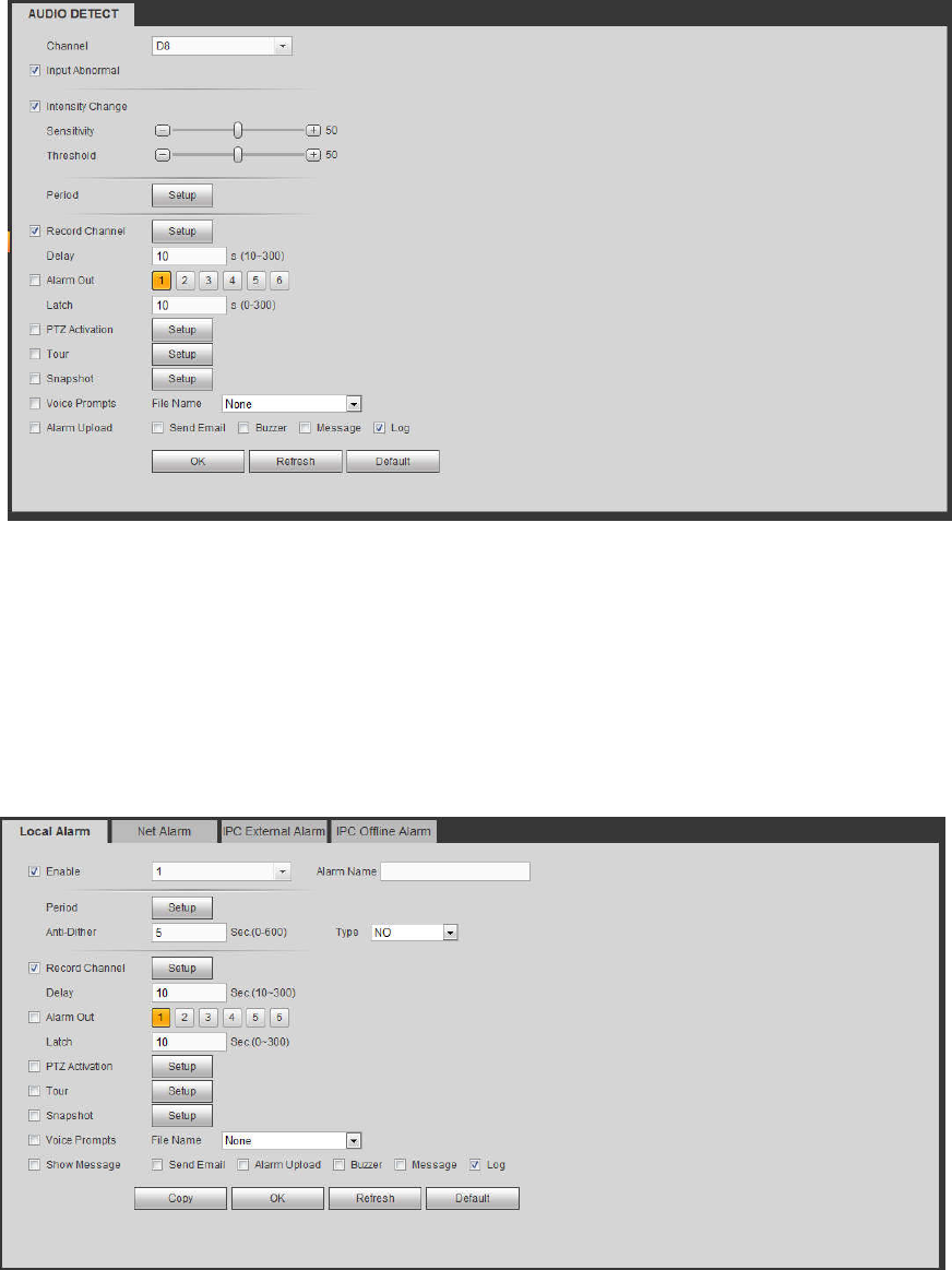
295
Intensity change: Check the box here, system can generate an alarm once the audio volume
becomes strong.
Sensitivity: It refers to the audio recognition sensitivity. The higher the value is, the higher the
sensitivity is.
Threshold: It is to set intensity change threshold. The smaller the value is, the higher the sensitivity
is.
For detailed setups, please refer to chapter 5.11.3.1.1 motion detect for detailed information.
Figure 5-93
5.11.3.9 Alarm
Before operation, please make sure you have properly connected alarm devices such as buzzer. The
input mode includes local alarm and network alarm.
5.11.3.9.1 Local Alarm
The local alarm interface is shown as in Figure 5-94. It refers to alarm from the local device.
Figure 5-94
296
Figure 5-95
Figure 5-96
Please refer to the following sheet for detailed information.
Parameter Function
Enable You need to check the box to enable this function.

297
Parameter Function
Please select a channel from the dropdown list.
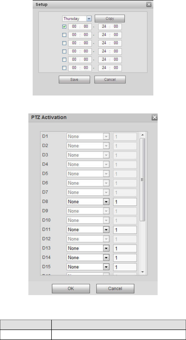
Period This function becomes activated in the specified periods.
There are six periods in one day. Please draw a circle to
enable corresponding period.
Select date. If you do not select, current setup applies to
today only. You can select all week column to apply to the
whole week.
Click OK button, system goes back to local alarm
interface, please click save button to exit.
Anti-dither System only memorizes one event during the anti-dither
period. The value ranges from 5s to 600s.
Sensor type There are two options: NO/NC.
Record channel System auto activates motion detection channel(s) to
record once an alarm occurs. Please note you need to set
alarm record period and go to Storage-> Schedule to set
current channel as schedule record.
Record Delay System can delay the record for specified time after alarm
ended. The value ranges from 10s to 300s.
Alarm out Enable alarm activation function. You need to select alarm
output port so that system can activate corresponding
alarm device when an alarm occurs.
Latch System can delay the alarm output for specified time after
an alarm ended. The value ranges from 1s to 300s.
Show message System can pop up a message to alarm you in the local
host screen if you enabled this function.
Buzzer Check the box here to enable this function. The buzzer
beeps when an alarm occurs.
Alarm upload System can upload the alarm signal to the center
(Including alarm center).
Send Email If you enabled this function, System can send out an email
to alert you when an alarm occurs.
Tour You need to click setup button to select tour channel.
System begins 1-wiindow or multiple-window tour display
among the channel(s) you set to record when an alarm
occurs. See Figure 5-64.
PTZ Activation Here you can set PTZ movement when alarm occurs.
Such as go to preset X. See Figure 5-96.
Snapshot Click setup button to select snapshot channel. See Figure
5-65.
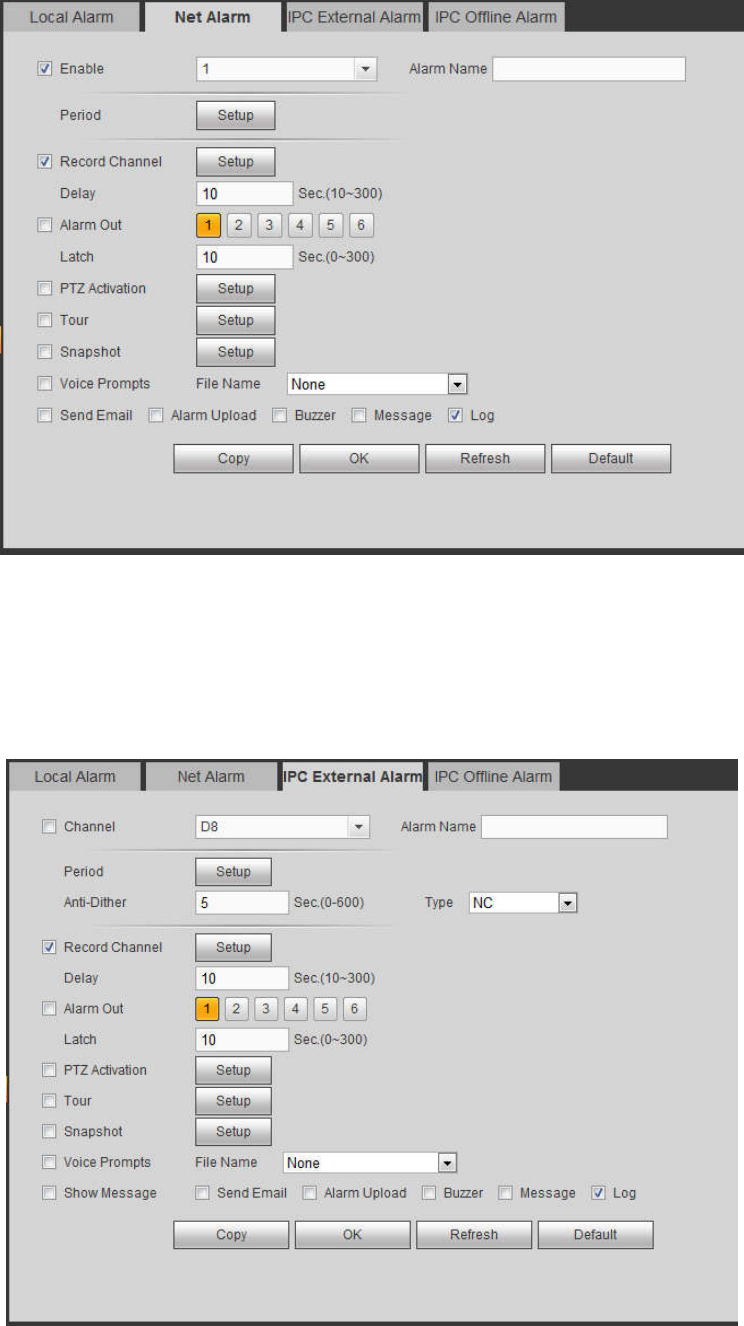
5.11.3.9.2 Net Alarm
The network alarm interface is shown as in Figure 5-97.
Network alarm refers to the alarm signal from the network. System does not anti-dither and sensor type
setup. For setup information, please refer to chapter 5.11.3.9.1.
298
Figure 5-97
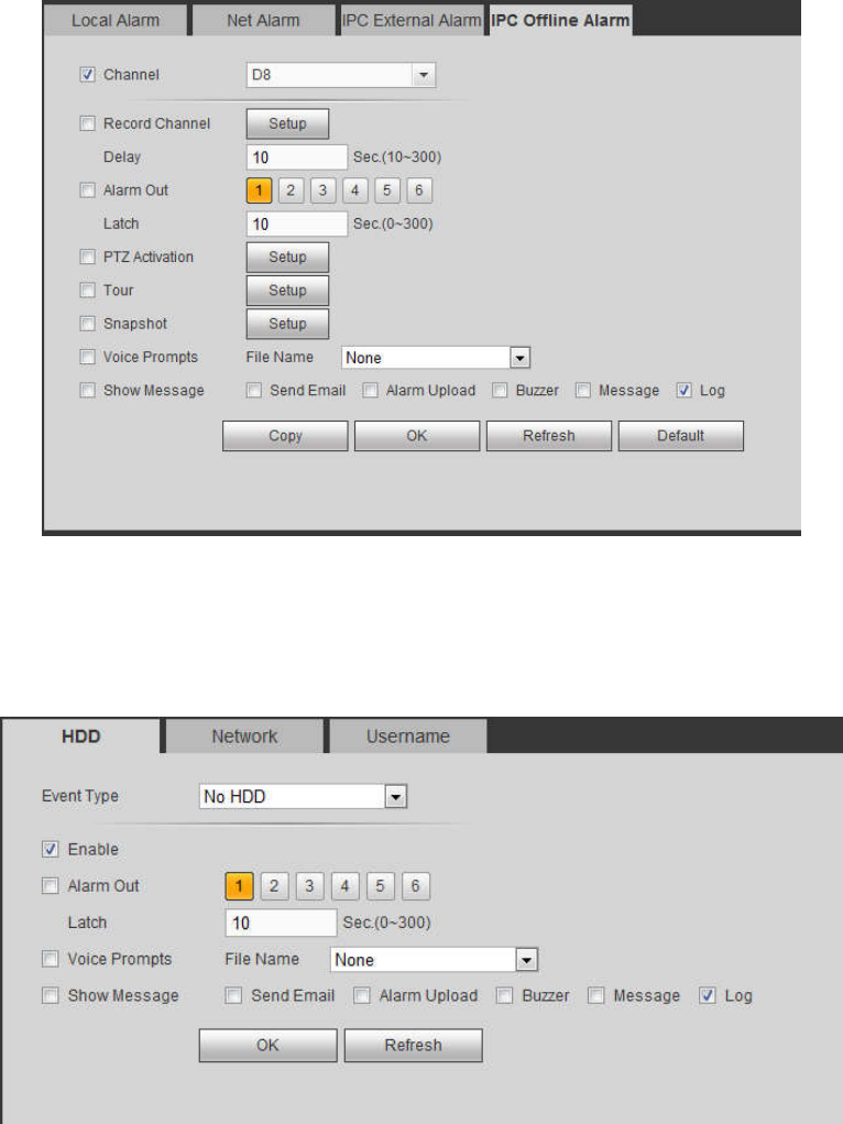
5.11.3.9.3 IPC external alarm
The IPC external alarm interface is shown as in Figure 5-98.
Network alarm refers to the alarm signal from the network. System does not anti-dither and sensor type
setup. For setup information, please refer to chapter 5.11.3.9.1.
Figure 5-98
5.11.3.9.4 IPC Offline Alarm
299
The IPC offline alarm interface is shown as in Figure 5-99.
System can generate an alarm once the network camera is offline. For setup information, please refer to
chapter 5.11.3.9.1.
Figure 5-99
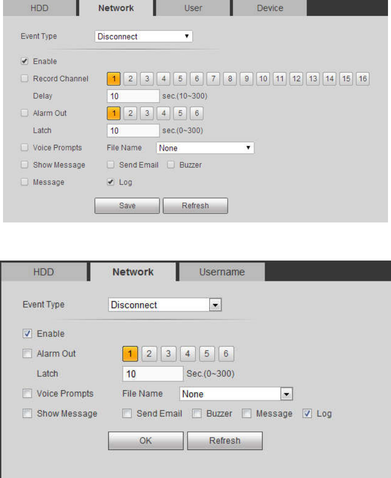
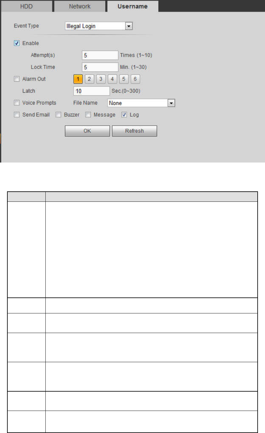
5.11.3.10 Abnormality
From main menu->Setup->Event->Abnormality, it includes four types: HDD/Network/User/Device. See
Figure 5-100 through Figure 5-103.
Figure 5-100
300
Figure 5-101
Figure 5-102
301
Figure 5-103
Please refer to the following sheet for detailed information.
Parameter
Function
Event
Type
The abnormal events include:
HDD: No disk, disk error, disk no space;
Network: Net disconnection, IP conflict, MAC conflict.
User: Illegal login.
Device: Temperature is too high, fan speed is abnormal. Please
note this function is for some series product only.
You can set one or more items here.
Less than: You can set the minimum percentage value here. The
device can generate an alarm when capacity is not sufficient. This
item is for disk no space type only.
Enable Check the box here to enable selected function.
Alarm Out Please select corresponding alarm output channel when an alarm
occurs. You need to check the box to enable this function.
Latch The alarm output can delay for the specified time after an alarm stops.
The value ranges from 0s to 300s. The default setup is 10 seconds. The
o second means there is no delaying time.
Attempt(s)
It is to set login attempt times. Once the login attempt exceeds the
threshold you set here, current account will be locked. This function is
for illegal login only.
Lock time It is to set account lock time once its login attempt has exceeded the
threshold you set. This function is for illegal login only.
Show
message
System can pop up a message to alarm you in the local host screen if
you enabled this function.
302
Parameter
Function
Alarm
upload
System can upload the alarm signal to the center (Including alarm
center.
Send
Email
If you enabled this function, System can send out an email to alert you
when an alarm occurs.
Buzzer Check the box here to enable this function. The buzzer beeps when an
alarm occurs.
Log Check the box here, system can record the network event alarm log.
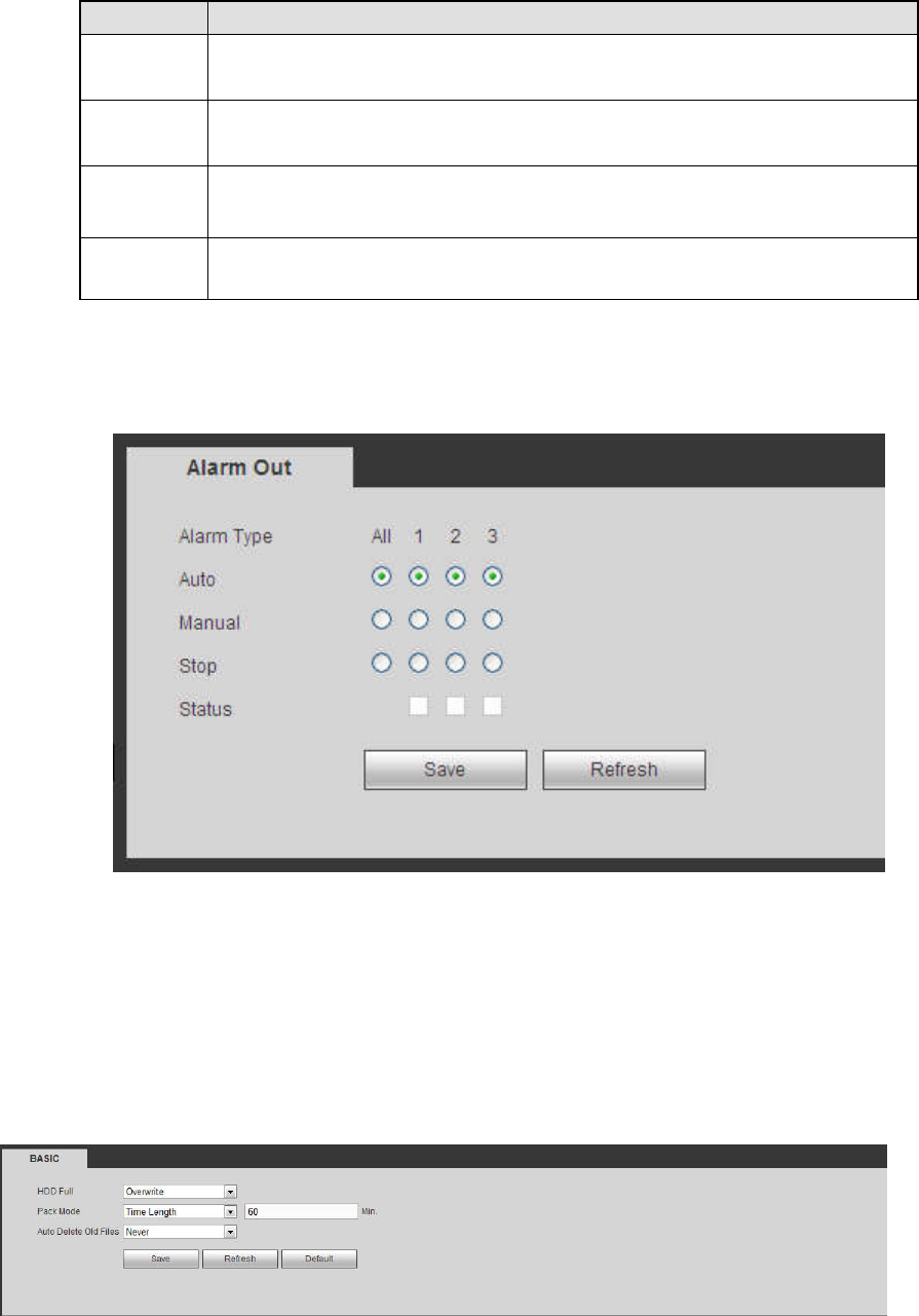
5.11.3.11 Alarm Out
The alarm output interface is shown as below. See Figure 5-104
Here you can set alarm output mode: auto/manual/stop.
Figure 5-104
5.11.4 Storage
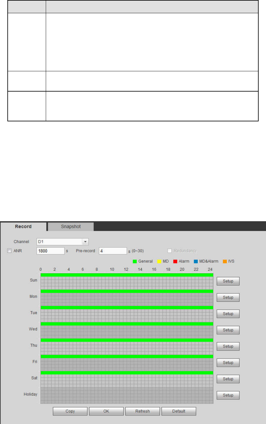
5.11.4.1 Basic
It is to manage HDD storage space.
Step 4 From main menu->Setup->Storage->Basic.
Enter Basic interface. See Figure 5-44.
Figure 5-105
Step 5 Set parameters.
303
Parameter Function
HDD full
It is to select working mode when hard disk is full. There are two options
stop recording or rewrite.
Stop: If current HDD is full while there is no idle HDD, then system
stops recording,
Overwrite: If the current HDD is full while there is no idle HDD, then
system overwrites the previous files.
Pack
duration
It is to specify record duration. The max value is 120 minutes.
Auto
delete old
files
Never: Do not auto delete old files.
Customized: input customized period here, system can auto delete
corresponding old files
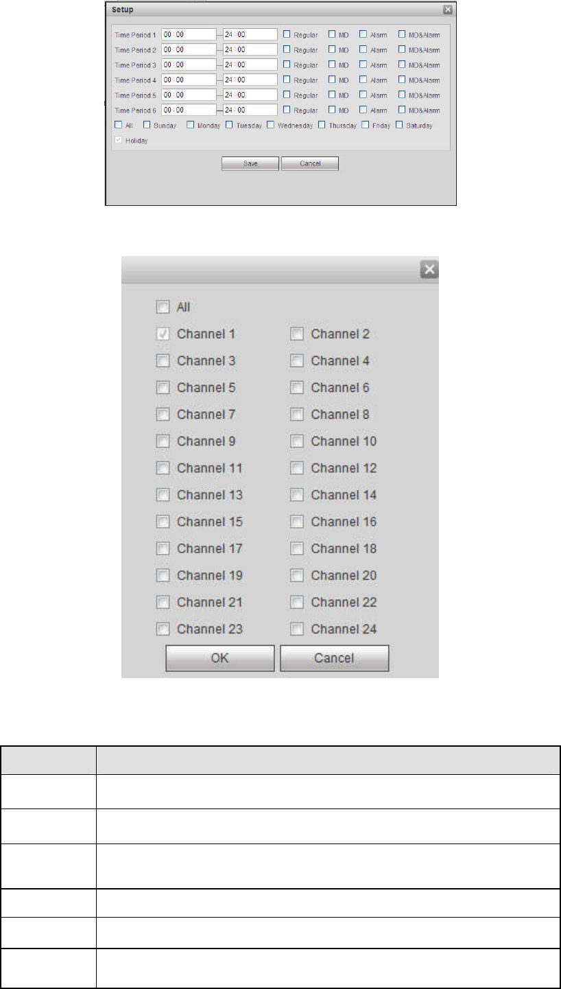
5.11.4.2 Schedule
In this interfaces, you can add or remove the schedule record setup. See Figure 5-106.
There are four record modes: general (auto), motion detect, alarm and MD&alarm. There are six periods
in one day.
You can view the current time period setup from the color bar.
Green color stands for the general record/snapshot.
Yellow color stands for the motion detect record/snapshot..
Red color stands for the alarm record/snapshot.
Blue color stands for MD&alarm record/snapshot.
Figure 5-106
304
Figure 5-107
Figure 5-108
Please refer to the following sheet for detailed information.
Parameter
Function
Channel Please select a channel from the dropdown list.
Pre-record Please input pre-record time here. The value ranges from 0 to 30.
Redundancy
Check the box here to enable redundancy function. Please note this
function is null if there is only one HDD.
Snapshot Check the box here to enable snapshot function.
Holiday Check the box here to enable holiday function.
Setup Click the Setup button, you can set record period. See Figure 5-107.
There are six periods in one day. If you do not check the date at the
305
Parameter
Function
bottom of the interface, current setup is for today only.
Please click Save button and then exit.
Copy Copy function allows you to copy one channel setup to another. After
setting in channel, click Copy button, you can go to interface Figure
5-108. You can see current channel name is grey such as channel 1.
Now you can select the channel you want to paste such as channel
5/6/7. If you want to save current setup of channel 1 to all channels,
you can click the first box “ALL”. Click the OK button to save current
copy setup. Click the OK button in the Encode interface, the copy
function succeeded.
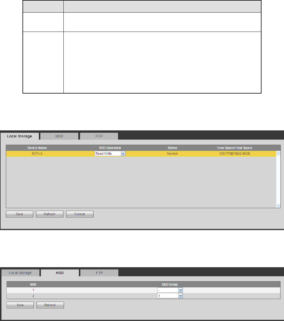
5.11.4.3 HDD Manager
5.11.4.3.1 Local Storage
The local interface is shown as in Figure 5-109. Here you can see HDD information. You can also operate
the read-only, read-write, redundancy (if there are more than on HDD) and format operation.
Figure 5-109
5.11.4.3.2 HDD
The HDD interface is to set HDD group. See Figure 5-110.
Figure 5-110
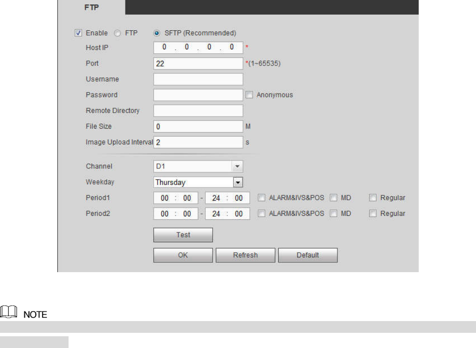
5.11.4.3.3 FTP
Configure FTP information on the FTP interface. See Figure 5-111.
Set the FTP as your remote storage location. System can save record file or snapshot picture to the FTP
once the network is offline or malfunction.
306
Figure 5-111
FTP transmits data with clear text mode and SFTP transmits data with encrypted mode. SFTP is
recommended.
Host IP: The host IP you have installed the FTP server.
Port: The default SFTP port number is 22 and the default FTP port number is 21.
User name/Password: The account for you to access the FTP server.
Remote directory: The folder you created under the root path of the FTP according to the
corresponding rule.
If there is no remote directory, system can auto create different directories according to the IP,
time and channel.
If there is remote directory, system can create corresponding folder under the FTP root path and
then create different folders according to IP address, time and channel.
File length: File length is upload file length. When setup is larger than the actual file length, system
will upload the whole file. When setup here is smaller than the actual file length, system only uploads
the set length and auto ignore the left section. When interval value is 0, system uploads all
corresponding files.
Image upload interval: It is the image upload interval. If the image upload interval is larger than the
image snapshot frequency, system just uploads the lasted image.
If the image interval is 5 seconds and the snapshot frequency is 2 seconds, system will send out
the latest image at the buffer at 5 seconds.
If the image upload interval is smaller than the snapshot frequency, system will upload at the
snapshot frequency. For example, if the image interval is 5 seconds and the snapshot frequency
is 10 seconds, system will send out the image at 10 seconds.
From main menu->Setting->Camera->Encode->Snapshot to set snapshot frequency.
Channel: Select a channel from the dropdown list and then set week, period and record type.
307
Week day/Period: Please select from the dropdown list and for each day, you can set two periods.
Type: Please select uploaded record type (Alarm/intelligent/motion detect/regular). Please check the
box to select upload type.
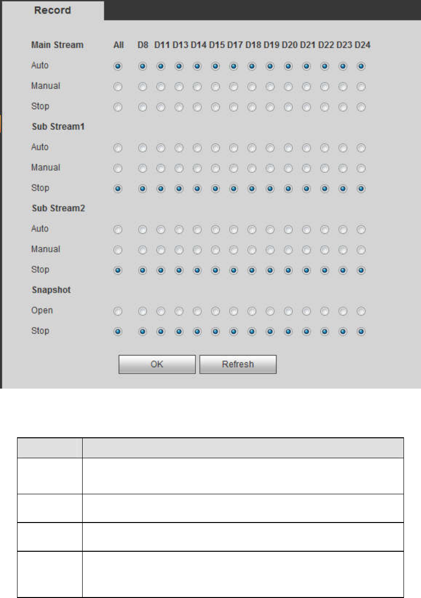
5.11.4.4 Record Control
The interface is shown as in Figure 5-112.
Figure 5-112
Please refer to the following sheet for detailed information.
Parameter
Function
Channel Here you can view channel number.
The number displayed here is the max channel amount of your
device.
Status There are three statuses: schedule, manual and stop.
Schedule System enables auto record function as you set in record schedule
setup (general, motion detect and alarm).
Manual It has the highest priority.
Enable corresponding channel to record no matter what period
applied in the record setup.
308
Stop Stop current channel record no matter what period applied in the
record setup.
Start all/
stop all
Check the corresponding All button, you can enable or disable all
channels record.
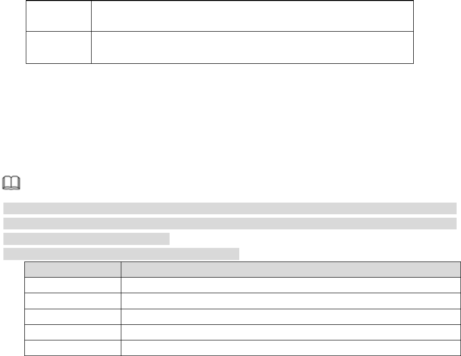
5.11.4.5 RAID Manager
Important
Please make sure your purchased product support the RAID function, otherwise you cannot see
the following interface.
RAID (redundant array of independent disks) is a data storage virtualization technology that combines
multiple physical HDD components into a single logical unit for the purposes of data redundancy,
performance improvement, or both.
Note
RAID function is for some series product only. Slight difference may be found on the user interface.
Right now, NVR supports RAID0, RAID1, RAID5, RAID6, and RAID 10. Local hotspare supports
RAID1, RAID5, RAID6, and RAID10.
Refer to the following table for detailed information.
RAID Type HDD Amount
RAID0 At least 2 HDDs.
RAID1 Only 2 HDDs.
RAID5 At least 3 HDDs. Usually recommend the RAID5 consists of 4 to 6 HDDs.
RAID6 At least 4 HDDs.
RAID10 At least 4 HDDs.
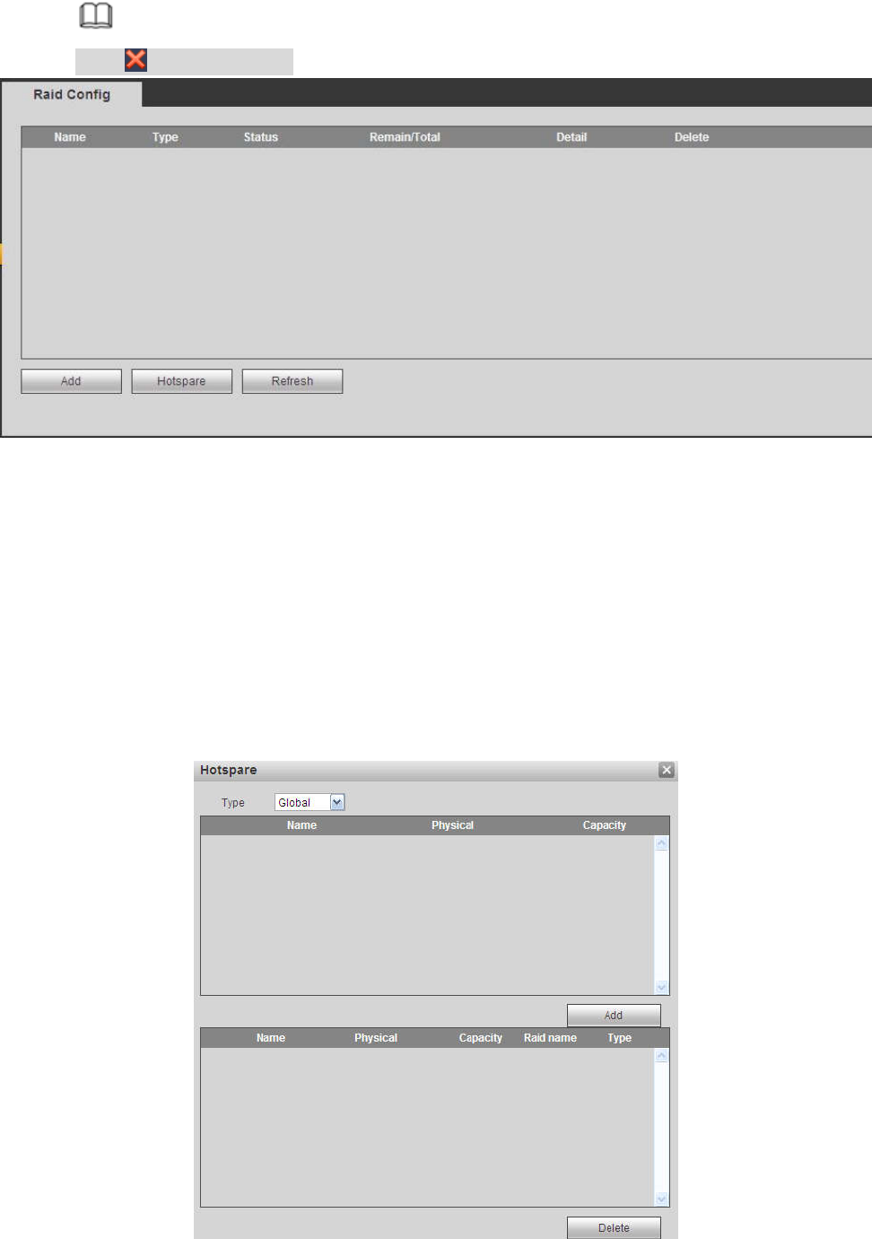
5.11.4.5.1 RAID Config
It is for you to manage RAID HDD. It can display RAID name, type, free space, total space, status and etc.
Here you can add/delete RAID HDD.
Click Add button to select RAID type and then select HDDs, click OK button to add. See Figure 5-113.
One click to create RAID
Click it to automatically create RAID5.
For create RAID function, you can select the physical HDD that does not included in the RAID group
or the created disk array to create a RAID5. You can refer to the following situations:
There is no RAID, no hotspare disk: System directly creates the RAID5 and creates one hotspare
disk at the same time.
There is no RAID, but there is a hotspare disk: System creates the RAID5 only. It uses previous
hotspare disk.
There is RAID: System cancel the previous RAID setup and then create the new RAID5. System
creates the hotspare disk if there is no one. System uses previous hotspare disk if there is hotspare
disk available.
The background will format the virtual disk.
Create manually
Step 4 Select RAID type first and then follow the prompts to set HDD amount.
Step 5 Click Create Manually button, system pops up dialogue box to warning you it is going to clear all
data.
Step 6 Click OK button to complete the operation.
309
Note
Click to delete RAID.
Figure 5-113
5.11.4.5.2 Hotspare disks
In Figure 5-113, click hotspare button, you can add the hot spare HDD. See Figure 5-114. The type
includes two options:
Global: It is global hotspare disk. When any RAID becomes degrading, it can replace and build the
RAID.
Local: It is local hotspare disk. When the specified RAID becomes degrading, it can replace and build
the RAID.
Select a hot spare device and then click Delete button. Click Apply button to delete.
Figure 5-114
310
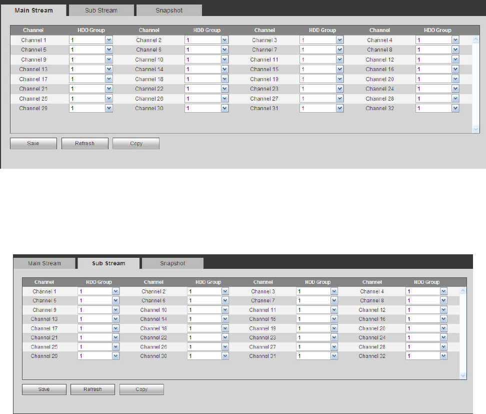
5.11.4.6 Storage
5.11.4.6.1 Main Stream
The main stream interface is shown as in Figure 5-115. Here you can set corresponding HDD group to
save main stream.
Figure 5-115
5.11.4.6.2 Sub Stream
The sub stream interface is shown as in Figure 5-116.
Here you can set corresponding HDD group to save sub stream.
Figure 5-116
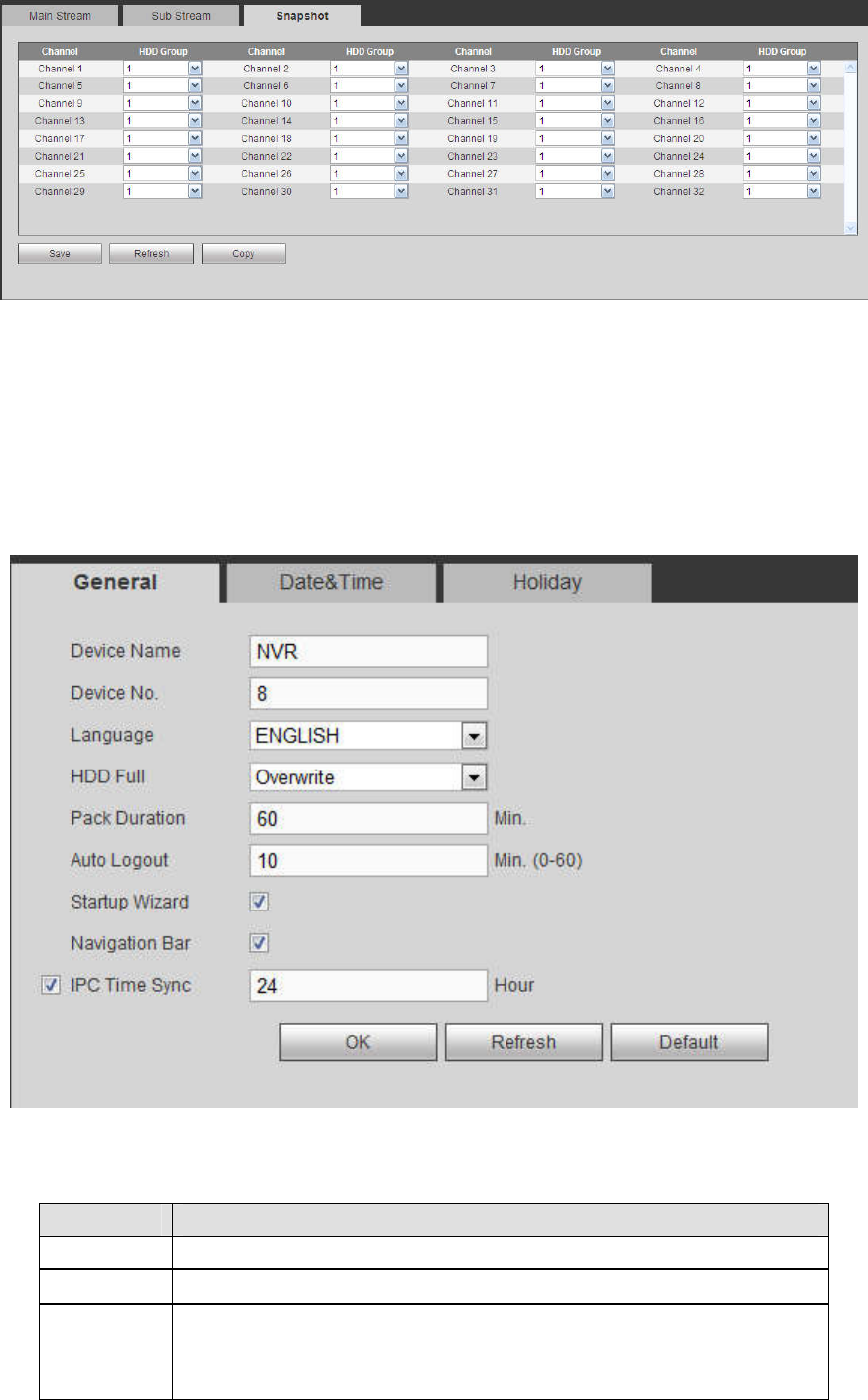
5.11.4.6.3 Snapshot
The snapshot interface is shown as in Figure 5-117. Here you can set corresponding HDD group to save
snapshot picture.
311
Figure 5-117
5.11.5 Setting
5.11.5.1 General
The general interface includes general, date/time and holiday setup.
5.11.5.1.1 General
The general interface is shown as in Figure 5-118.
Figure 5-118
Please refer to the following sheet for detailed information.
Parameter
Function
Device ID It is to set device name.
Device No. It is device channel number.
Language You can select the language from the dropdown list.
Please note the device needs to reboot to get the modification
activated.
312
Video
Standard
This is to display video standard such as PAL.
Auto logout
Here is for you to set auto logout interval once login user remains
inactive for a specified time. Value ranges from 0 to 60 minutes.
IPC Time
Sync
You can input an interval here to synchronize the NVR time and IPC
time.
Navigation
bar
Check the box here, system displays the navigation bar on the
interface.
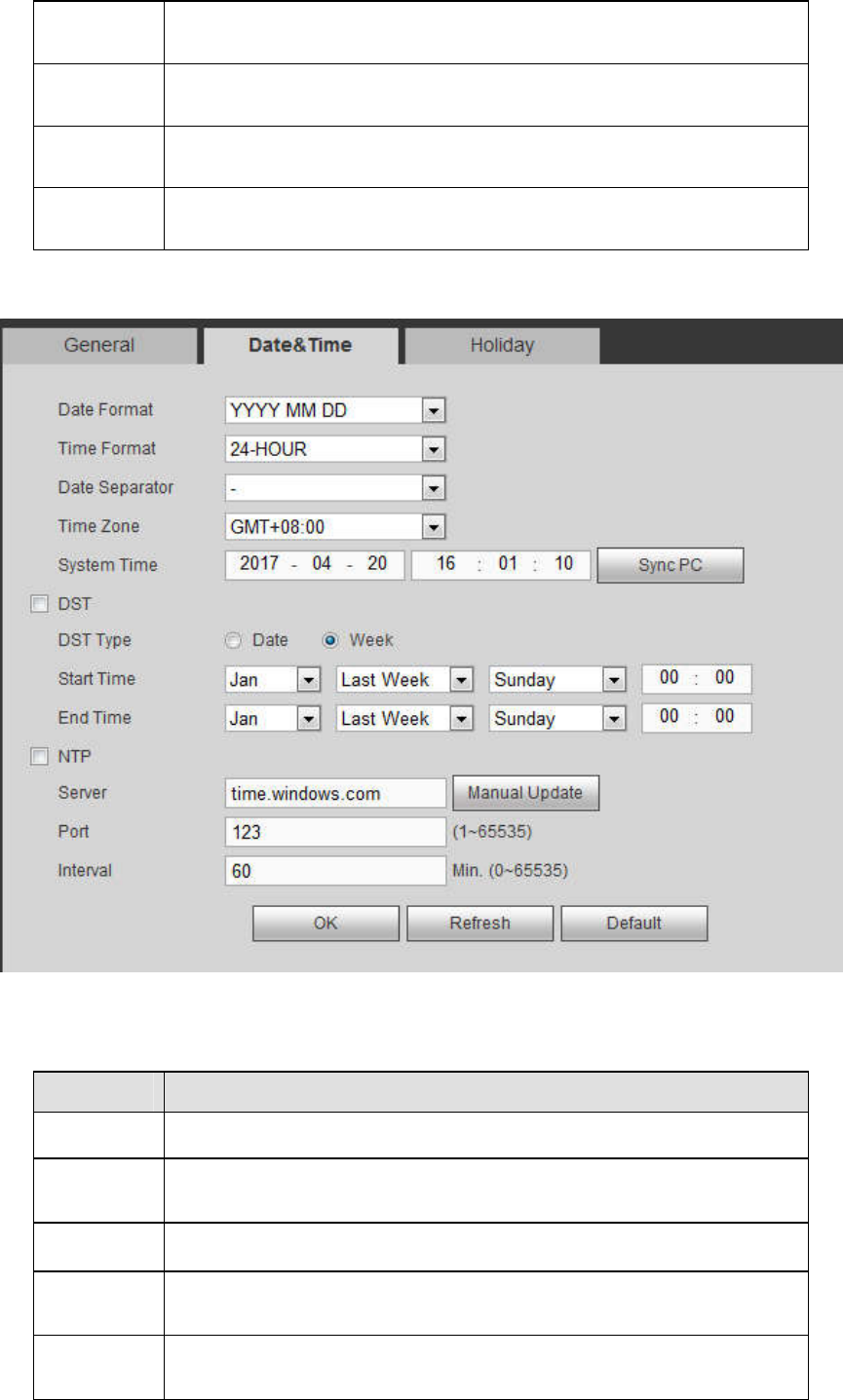
5.11.5.1.2 Date and time
The date and time interface is shown as in Figure 5-119
Figure 5-119
Please refer to the following sheet for detailed information.
Parameter
Function
Date format
Here you can select date format from the dropdown list.
Time
Format
There are two options: 24-H and 12-H.
Time zone
The time zone of the device.
System
time
It is to set system time. It becomes valid after you set.
Sync PC You can click this button to save the system time as your PC current
time.
313
DST Here you can set day night save time begin time and end time. You
can set according to the date format or according to the week format.
NTP You can check the box to enable NTP function.
NTP server
You can set the time server address.
Port It is to set the time server port.
Interval It is to set the sync periods between the device and the time server.
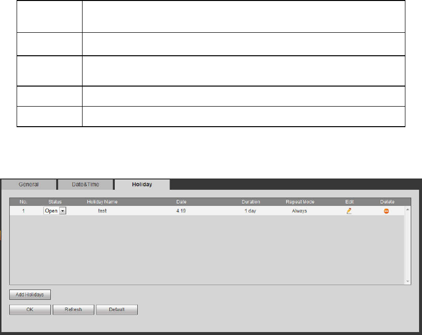
5.11.5.1.3 Holiday Setup
Holiday setup interface is shown as in Figure 5-120.
Here you can click Add holidays box to add a new holiday and then click Save button to save.
Figure 5-120
5.11.5.2 Display
Display interface includes GUI, TV adjust, Tour and Customized split.
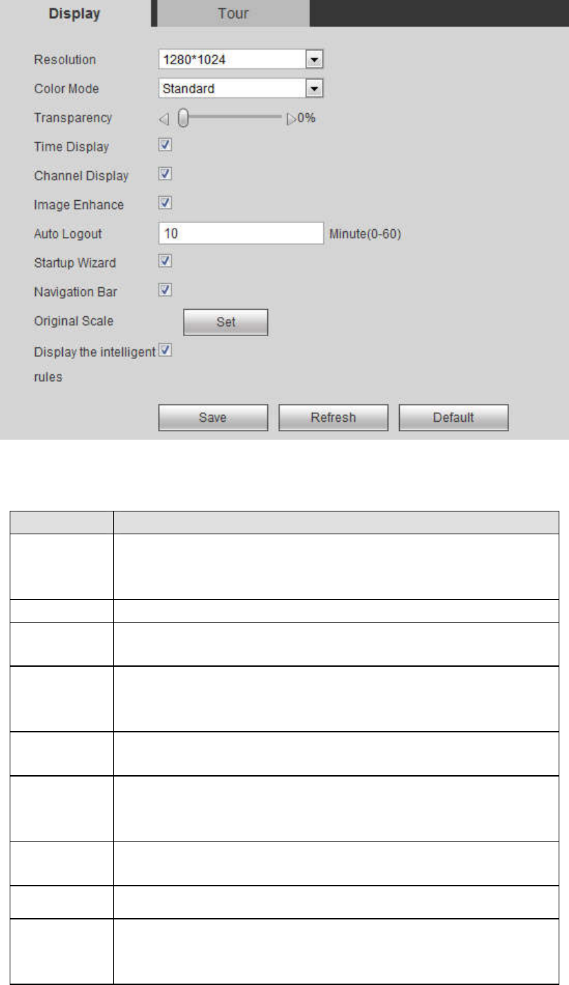
5.11.5.2.1 Display
Here you can set background color and transparency level. See Figure 5-121.
314
Figure 5-121
Please refer to the following sheet for detailed information.
Parameter Function
Resolution There are four options: 1920×1080, 1280×1024(default),
1280×720, 1024×768. Please note the system needs to reboot to
activate current setup.
Color mode Please select from the dropdown list.
Transparency
Here is for you to adjust transparency. The value ranges from 128
to 255.
Time
title/channel
title
Check the box here, you can view system time and channel
number on the monitor video.
Image
enhance
Check the box; you can optimize the margin of the preview video.
Startup
wizard
Once you check the box here, system will go to the startup wizard
directly when the system restarts the next time. Otherwise, it will go
to the login interface.
Navigation
bar
Check the box here, system displays the navigation bar on the
interface.
Original scale
Click the Set button to select a channel, it can restore original scale.
Auto logout Here is for you to set auto logout interval once login user remains
inactive for a specified time. Value ranges from 0 to 60 minutes. 0
means there is no standby time. After the auto logout, the user
315
needs to input user name and password to login again.
Display
intelligent
rule(s)
Check the box to enable IVS function, system can display IVS rule
on the preview interface.
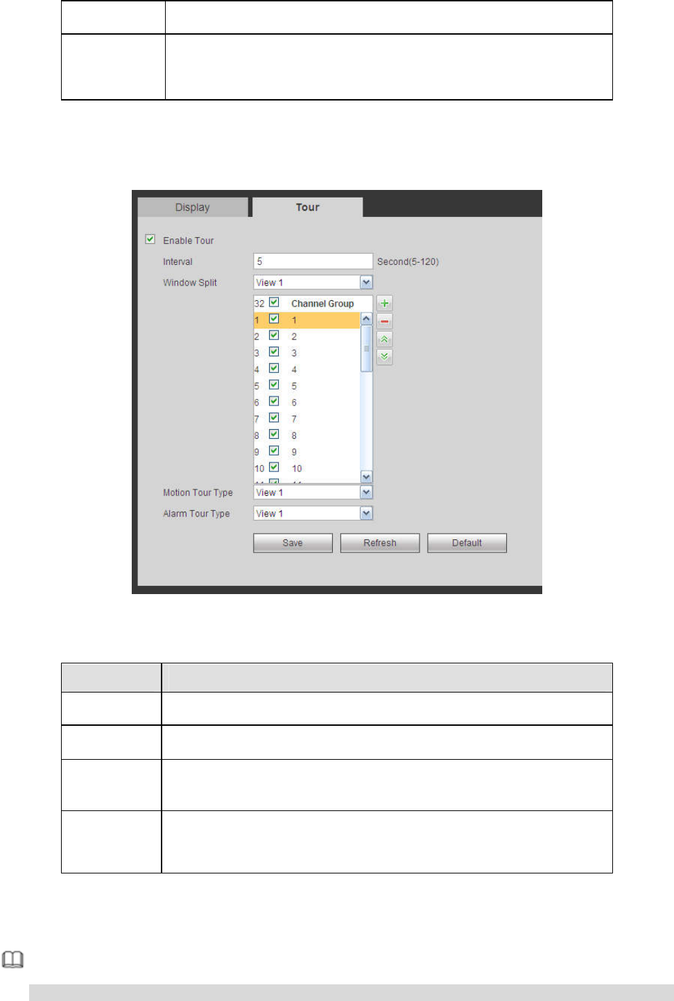
5.11.5.2.2 Tour
The tour interface is shown as in Figure 5-122. Here you can set tour interval, split mode, motion detect
tour and alarm tour mode.
Figure 5-122
Please refer to the following sheet for detailed information.
Parameter Function
Enable tour
Check the box here to enable tour function.
Interval Here is for you to adjust transparency. The value ranges from 5 to
120s. The default setup is 5s.
Split Here you can set window mode and channel group. System can
support 1/4/8/9/16/25/36-window according to device channel
amount.
Motion
tour/Alarm
tour
Here you can set motion detect tour/alarm tour window mode.
System supports 1/8-window now.
5.11.5.2.3 Custom Split
From main menu->Setup->System->Display->Custom split, the interface is shown as in Figure 5-123.
Here you can set customized split mode.
Note
This function is for some series products. Please refer to the actual product for detailed information.
316
Device max supports 5 customized videos.
Figure 5-123
Click and then click to select basic mode
In regular mode, drag the mouse in the preview frame, you can merge several small windows to one
window so that you can get you desired split mode.
After the setup, the selected window has the red frame.
Select the merging window, the frame is red; you can click to cancel the merge to restore regular
mode.
Click OK to exit.
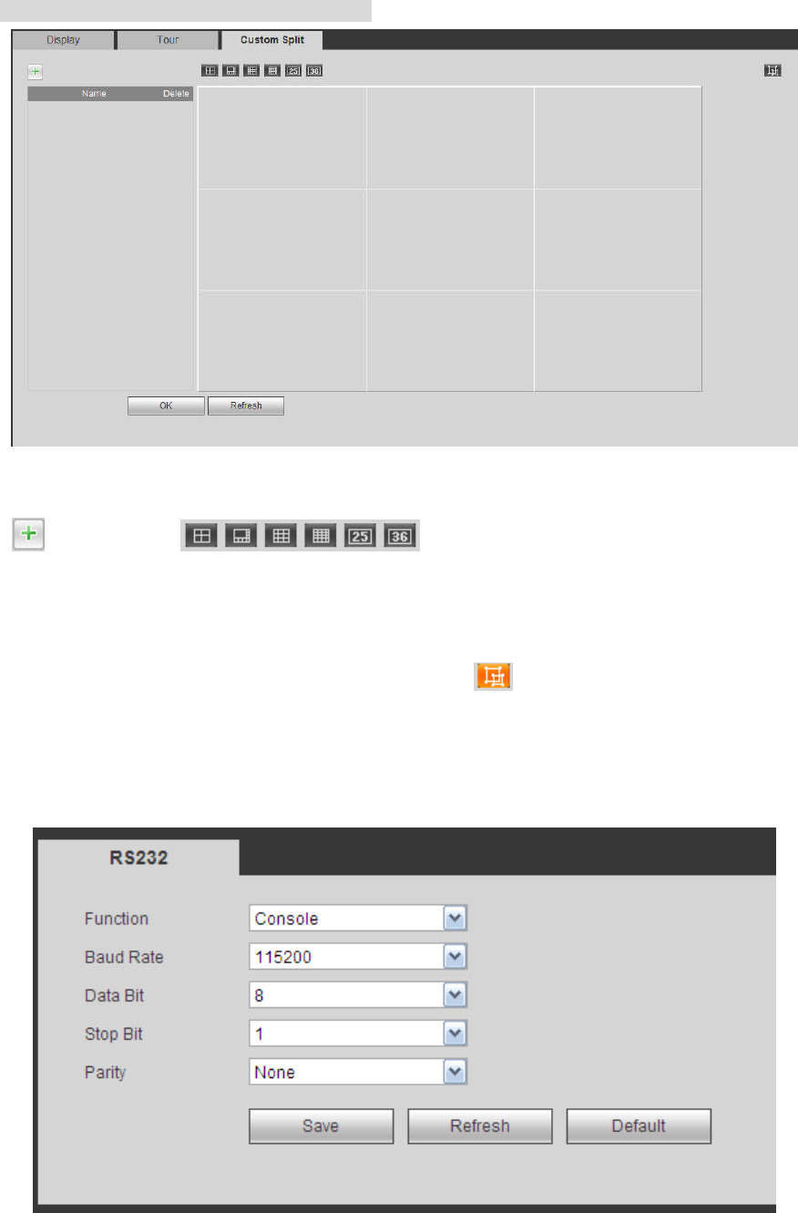
5.11.5.3 RS232
The RS232 interface is shown as in Figure 5-124.
Figure 5-124
Please refer to the following sheet for detailed information.
317
Parameter Function
Protocol Select the corresponding dome protocol.
Default setup is console.
Baud Rate
Select the baud rate.
Default setup is 115200.
Data Bit The value ranges from 5 to 8.
Default setup is 8.
Stop bit There are two options: 1/2.
Default setup is 1.
Parity There are five options: none/odd/even/space/mark.
Default setup is none.
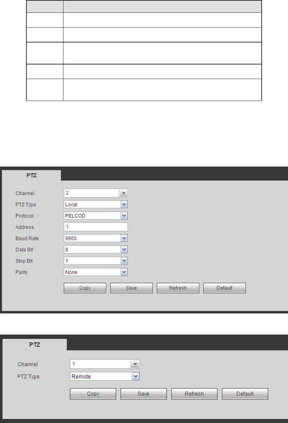
5.11.5.4 PTZ
The PTZ interface is shown as in Figure 5-125 (Local) and Figure 5-126 (Remote).
Before setup, please check the following connections are right:
PTZ and decoder connection is right. Decoder address setup is right.
Decoder A (B) line connects with NVR A (B) line.
Click Save button after you complete setup, you can go back to the monitor interface to control speed
dome.
Figure 5-125

318
Figure 5-126
Please refer to the following sheet for detailed information.
Parameter Function
Channel Select speed dome connected channel.
PTZ Type
There are two options: local/remote.
Please select remote type if you are connecting to the network PTZ.
Please select local type if you are using RS485 to the PTZ camera.
Protocol Select the corresponding dome protocol such as PELCOD.
Address Set corresponding dome address. Default value is 1. Please note
your setup here shall comply with your dome address; otherwise
you cannot control the speed dome.
Baud
Rate
Select the dome baud rate. Default setup is 9600.
Data Bit The value ranges from 5 to 8. Default setup is 8. Please set according
to the speed dome dial switch setup.
Stop bit The value ranges from 1 to 2. Default setup is 1. Please set according
to the speed dome dial switch setup.
Parity The options include non/odd/even/space/null. Default setup is none.
Please set according to the speed dome dial switch setup.
5.11.5.5 POS
Connect the NVR to the POS, it can receive the POS information and overlay on the corresponding
record.
Note
POS info overlay and playback function is for 1-window only.
From main menu->Setting->System->POS, you can go to the following interface. See Figure 5-127.
Figure 5-127
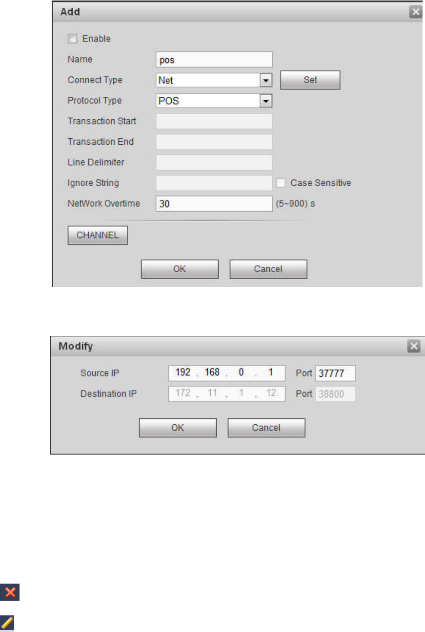
Click Add, you can see the following dialogue box. See Figure 5-128.
319
Figure 5-128
Check the box to enable POS function, Click Set button; you can see the following interface. See Figure
5-129.
Figure 5-129
Set source IP and destination IP, and then click OK. System goes back to Figure 5-128.
Source IP: POS device IP address.
Destination IP: NVR IP address.
In Figure 5-128, click Channel Set button, select the channel you want to overlay POS information. Click
OK button to complete the setup.
Tips
: Click it to delete POS setup.
: Click it to change setup information.
5.11.5.6 Voice
The audio function is to manage audio files and set schedule play function. It is to realize audio broadcast
activation function.
320
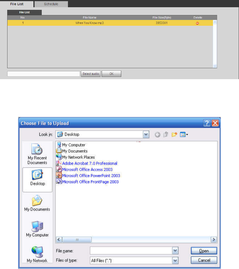
5.11.5.6.1 File List
From main menu->Setup->System->Voice->File list, here you can add audio file, or delete audio file. See
Figure 5-130.
Figure 5-130
Click Add button, you can add audio file and import the audio file via the local computer. See Figure
5-131.
Figure 5-131
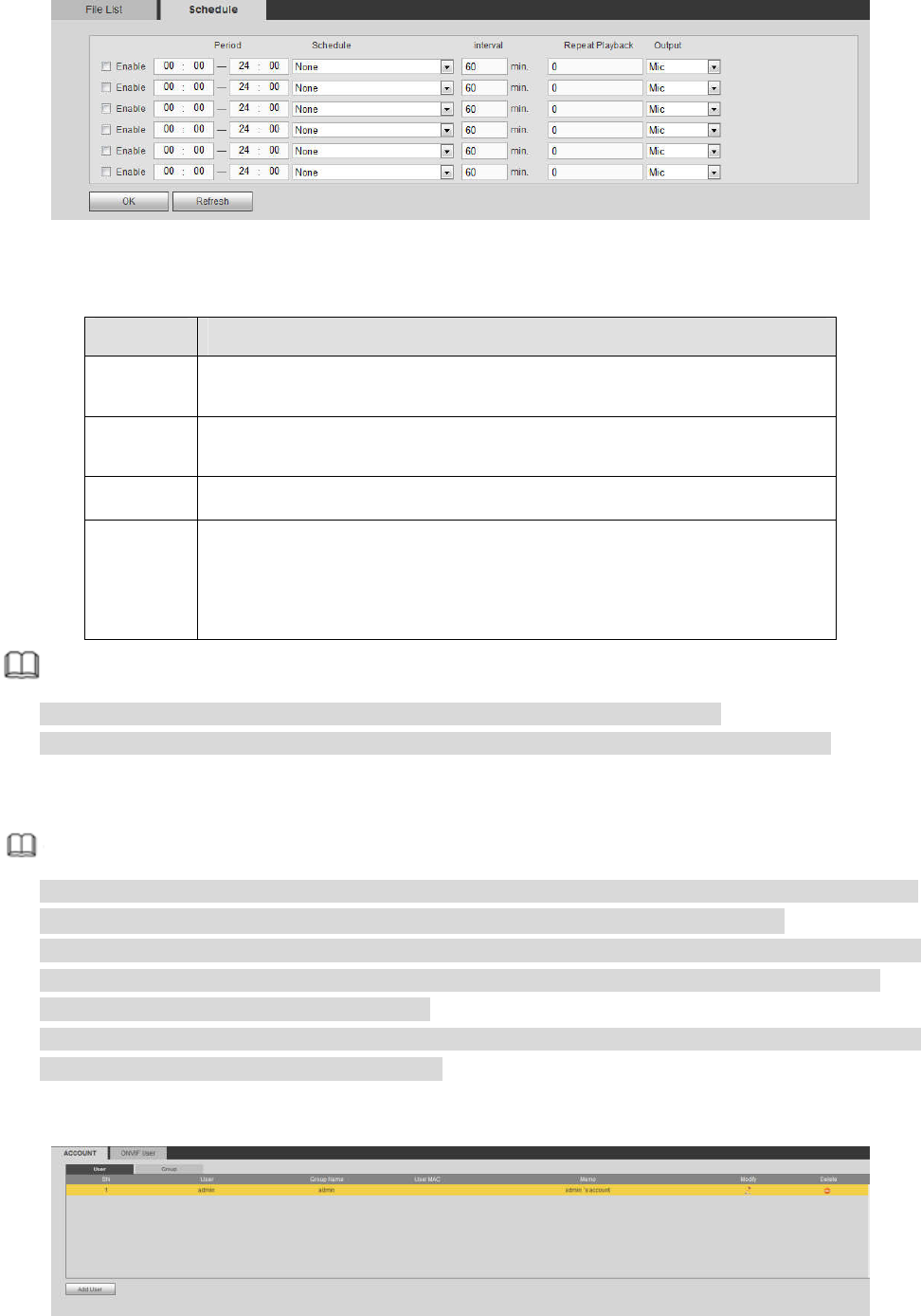
5.11.5.6.2 Schedule
It is to set schedule broadcast function. You can play the different audio files in the specified periods.
From main menu->Setup->System->Voice->.Schedule, you can see the following interface. See Figure
5-132.
321
Figure 5-132
Please refer to the following sheet for detailed information.
Parameter Function
Period There are six periods. Check the box to enable current setup.
Repeat It is to set audio file repeat times in the specified period.
Interval It is the audio file repeated interval in the specified period.
Output
port
There are two options: MIC (default)/audio. When reuse the MIC port
and bidirectional talk port, the bidirectional port has the higher priority.
Please note some series product does not support audio function.
Note
The audio file end time depends on the audio file size and the interval setup.
Priority: Bidirectional talk>Event trigger alarm>Trial listening>Audio schedule broadcast.
5.11.5.7 Account
Note
For the user name, the string max length is 31-byte, and for the user group, the string max length is
15-byte. The user name can only contain English letters, numbers and “_”、“@”、“.”.
The default user amount is 64 and the default group amount is 20. System account adopts two-level
management: group and user. The user authorities shall be smaller than group authorities (The
admin user authorities are set by default).
For group or user management, there are two levels: admin and user. The user name shall be unique
and one user shall only belong to one group.
5.11.5.7.1 User name
From main menu->Setup->System->Account->Account, enter account interface. See Figure 5-133.
Figure 5-133
322
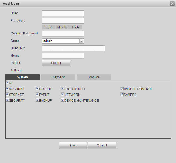
Add user
It is to add a name to group and set the user rights.
Step 1 Click Add user button.
Enter add user interface. See Figure 5-134.
Step 2 Here you can input the user name and password and then select one group for current user.
Figure 5-134
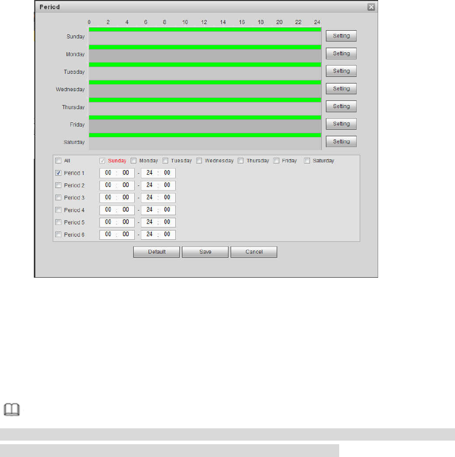
Step 3 Click the Set button after the period. It is to set valid period to use current account. See Figure
5-135.
323
Figure 5-135
Click Setting to set the periods. Or you can draw on the interface directly. There are six
periods in one day. Or you can input start time and end time directly.
Check the box before the date, the settings are for the selected date(s).
Check the box before the period1-6, it is to enable the period function.
Step 4 Click Save to complete the setup.
Note
Please note the user rights shall not exceed the group right setup. For convenient setup, please
make sure the general user has the lower rights setup than the admin.
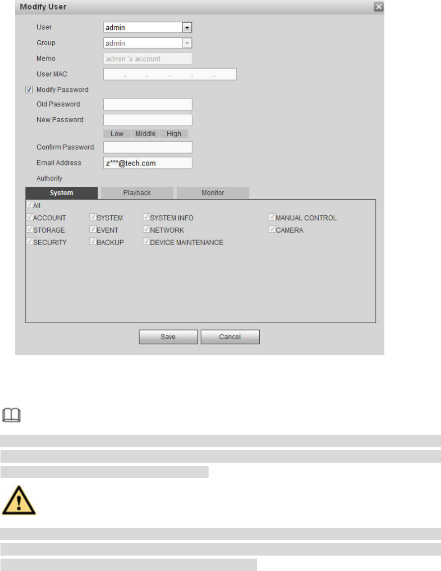
Modify user
It is to modify the user property, belonging group, password and rights. See Figure 5-136.
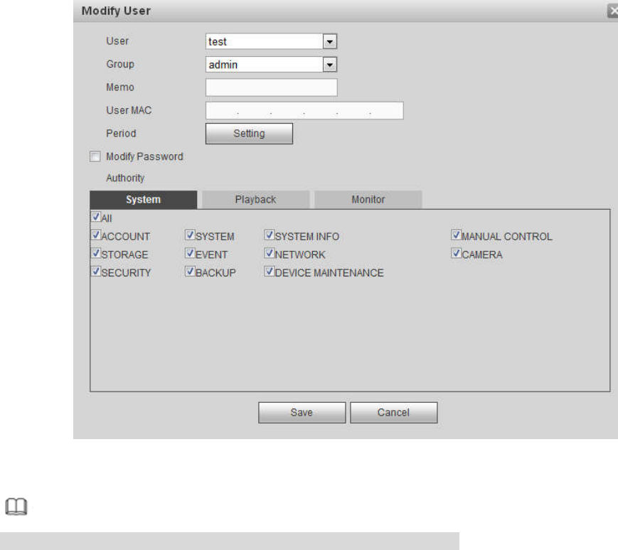
324
Figure 5-136
Note
For admin, you can change the email information. See Figure 5-137.
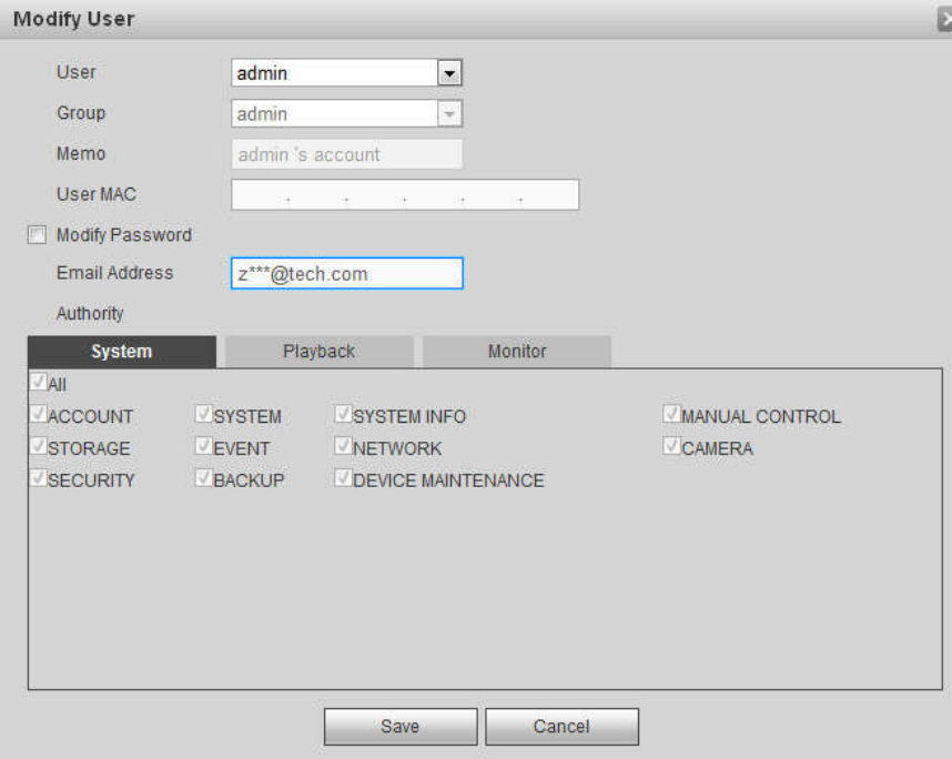
325
Figure 5-137
Modify password
It is to modify the user password.
Step 1 In Modify user interface, click Modify password box. See Figure 5-138.
326
Figure 5-138
Step 2 Input old password, and then input new password and confirm.
Step 3 Click Save button.
Note
The password ranges from 8 to 32 digitals. It can contain letters, numbers and special
characters (excluding “'”,“"”,“;”,“:”,“&”) . The password shall contain at least two categories.
Usually we recommend the strong password.
WARNING
STRONG PASSWORD RECOMMENDED-For your device own safety, please create a
strong password of your own choosing. We also recommend you change your password
periodically especially in the high security system.
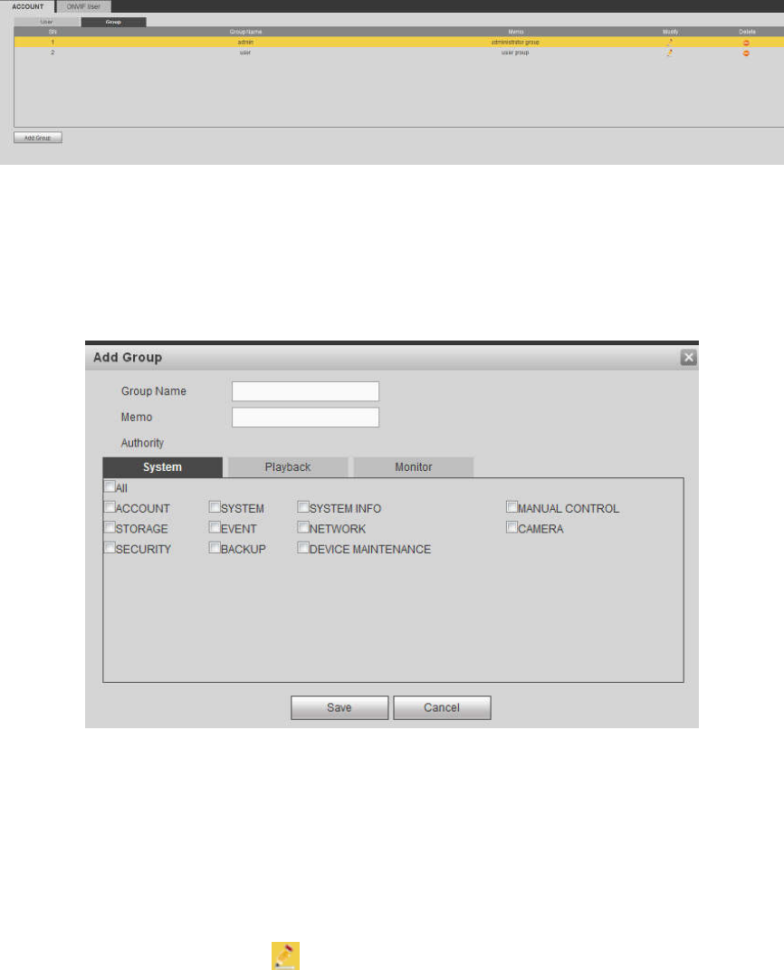
5.11.5.7.2 Group
It is to add/remove group, modify group password and etc.
From main menu->Setup->System->Account->Account.
Click Group tab, the interface is shown as in Figure 5-139.
327
Figure 5-139
Add group
It is to add group and set its corresponding rights.
Step 1 Click Add group button. Enter add group interface. See Figure 5-140.
Figure 5-140
Step 2 Input the group name and then check the box to select the corresponding rights. It includes:
system, playback, and monitor.
Step 3 Click Save button.
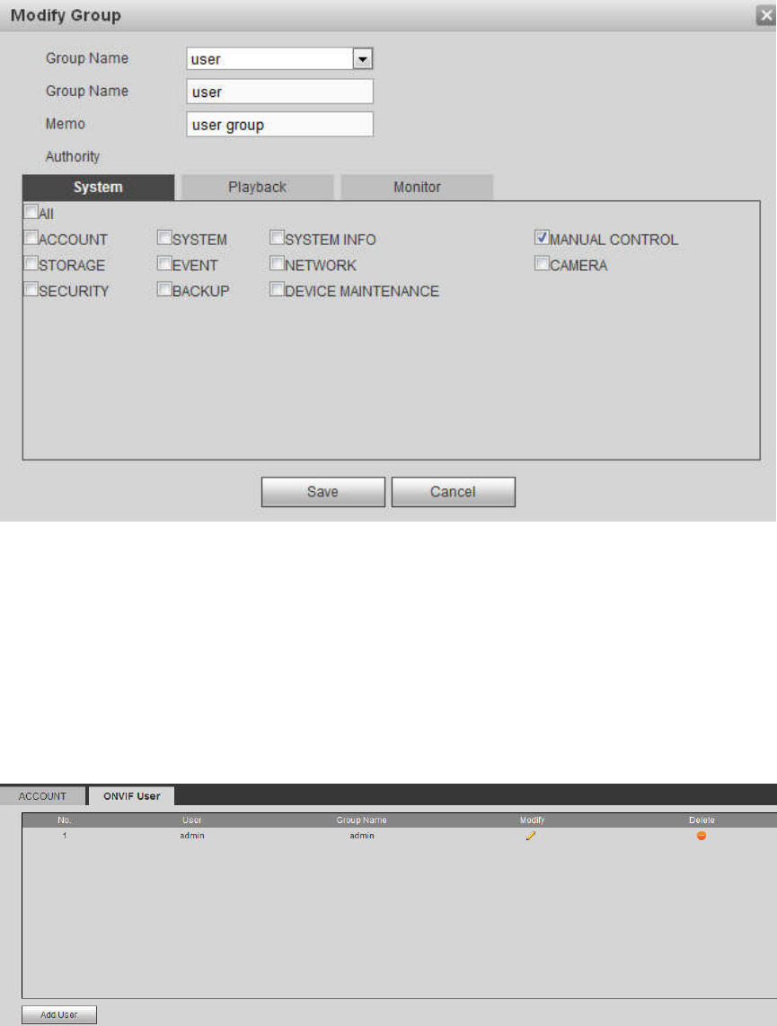
Modify group
Step 1 Select a group and then click . See Figure 5-141.
328
Figure 5-141
Step 2 Change corresponding information and then click Save button.
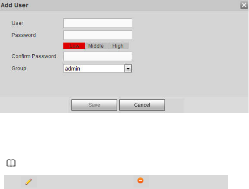
5.11.5.7.3 ONVIF User
When the camera from the third party is connected with the NVR via the ONVIF user, please use the
verified ONVIF account to connect to the NVR.
Step 1 From main menu->Setting->System->Account->ONVIF User.
Enter ONVIF user interface. See the following figure.
Figure 5-142
Step 2 Click Add user button.
Enter add user interface. See Figure 5-143.
329
Figure 5-143
Step 3 Set user name, password and then select group from the dropdown list.
Step 4 Click Save to complete setup.
Note
Click to change user information, click to delete current user.
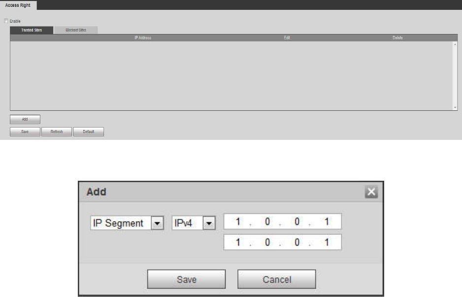
5.11.5.8 Security
To enhance device network security and protect device data, please set the access right of the IP host (IP
host here refers to the IP PC or the server). After you enabled trusted sites function, only the IP listed
below can access current NVR.
If you enable blocked sites function, the following listed IP addresses cannot access current NVR.
Step 1 From main menu->Setting->System->Security.
Enter security interface. See Figure 5-144.
Step 2 Check the Enable box.
Select trusted sites/block sites.
Enable trusted site function and then add the whitelist.
Enable blocked site function and then add the blacklist.
Step 3 Set parameters.
Start address/end address: Select one type from the dropdown list, you can input IP address in the
start address and end address. Now you can click Add IP address or Add IP section to add. System
supports max 64 IP addresses.
a) For the newly added IP address, it is in enable status by default. Remove the √ before the item,
and then current item is not in the list.
b) System max supports 64 items.
c) Address column supports IPv4 or IPv6 format. If it is IPv6 address, system can optimize it. For
example, system can optimize aa:0000: 00: 00aa: 00aa: 00aa: 00aa: 00aa as aa:: aa: aa: aa: aa:
aa: aa.
d) System automatically removes space if there is any space before or after the newly added IP
address.
e) System only checks start address if you add IP address. System check start address and end
address if you add IP section and the end address shall be larger than the start address.
330
f) System may check newly added IP address exists or not. System does not add if input IP
address does not exist.
Delete: Click it to remove specified item.
Edit: Click it to edit start address and end address. See Figure 5-145. System can check the IP
address validity after the edit operation and implement IPv6 optimization.
Default: Click it to restore default setup. In this case, the trusted sites and blocked sites are both null.
Step 4 Click Save to complete setup.
If you enabled trusted sites, only the IP in the trusted sites list can access the device.
If you enabled blocked sites, the IP in the blocked sites cannot access the device.
Figure 5-144
Figure 5-145
5.11.5.9 Auto maintain
The auto maintain interface is shown as in Figure 5-146.
Here you can select auto reboot and auto delete old files interval from the dropdown list.
If you want to use the auto delete old files function, you need to set the file period.
Click Manual reboot button, you can restart device manually.
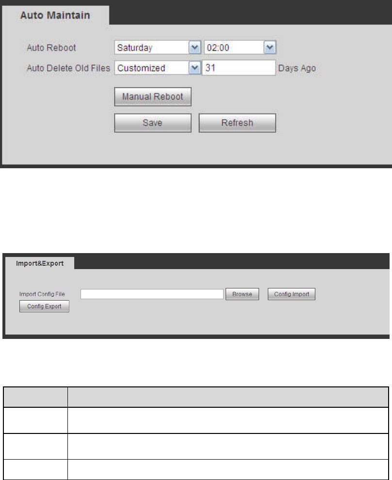
331
Figure 5-146
5.11.5.10 Import/Export
The interface is shown as in Figure 5-147. This interface is for you to export or import the configuration
files.
Figure 5-147
Please refer to the following sheet for detailed information.
Parameter
Function
Browse Click to select import file.
Import It is to import the local setup files to the system.
Export It is to export the corresponding WEB setup to your local PC.
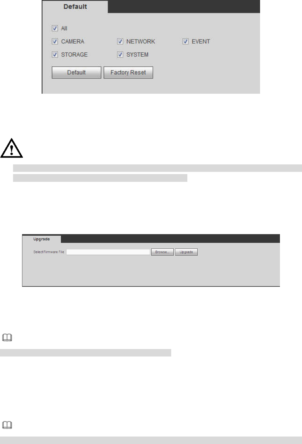
5.11.5.11 Default
The default setup interface is shown as in Figure 5-148.
Here you can select Network/Event/Storage/Setting/Camera. Or you can check the All box to select all
items.
332
Figure 5-148
5.11.5.12 Upgrade
CAUTION
During the upgrade process, do not unplug the power cable, network cable, or shutdown the device.
Improper upgrade program may result in device malfunction!
There are two upgrade modes: file upgrade and online upgrade.
5.11.5.12.1 File Upgrade
The upgrade interface is shown as in Figure 5-149.
Please select the upgrade file and then click the update button to begin update. Please note the file name
shall be as *.bin.
Figure 5-149
5.11.5.12.2 Cloud Upgrade
When the NVR is online, you can use the cloud upgrade to update the firmware.
Note
Make sure the NVR has properly connected to the network.
Version Detection
The version detection includes auto detection and manual detection. It displays current system version
and application released date.
Enable auto detection, NVR interacts with the cloud every day to detect if there is a new version
available. When there is a new version, system marks a red point on the Upgrade tab.
Note
To inform you upgrading firmware timely, we will collect your device information such as IP address,
333
device name, firmware version and serial number. The collected information is used for verifying device
legality and pushing upgrade notice.
Click manual detection to view the latest new version on the cloud.
If current version is the latest one, system prompts that “It is the latest version”.
If there is new version available, system displays new version information such as release date
and corresponding release note.
Upgrade System
Click Start to upgrade the system.
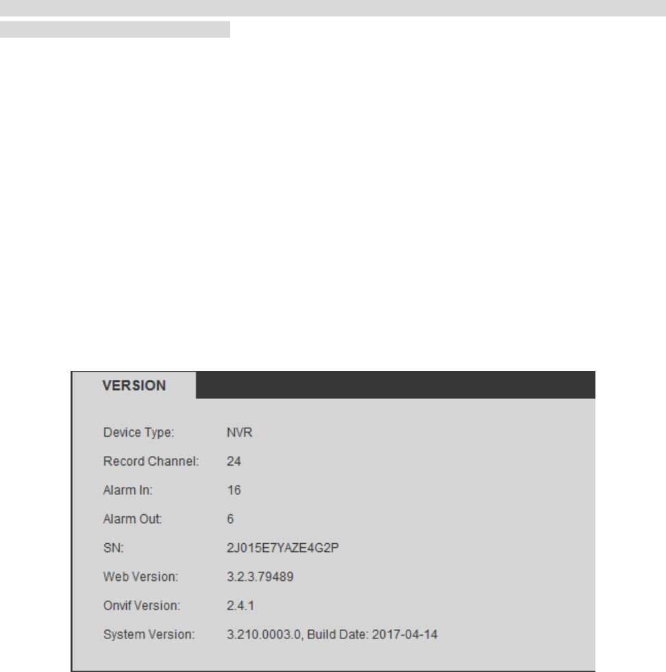
5.12 Information
5.12.1 Version
The version interface is shown as in Figure 5-150. Please note the following information for reference
only.
Here you can view record channel, alarm input/output information, software version, release date and etc.
When there is any new version, it prompts found new version. Click it, NVR goes to upgrade interface.
Figure 5-150
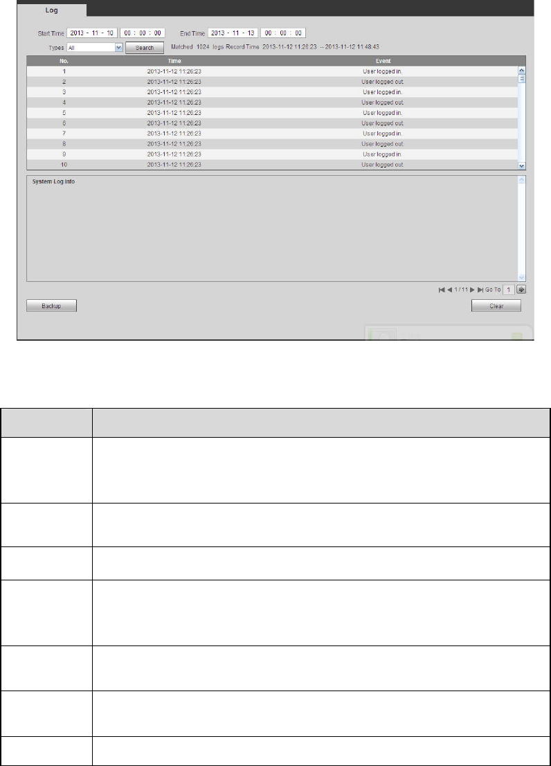
5.12.2 Log
Here you can view system log. See Figure 5-151.
334
Figure 5-151
Please refer to the following sheet for log parameter information.
Parameter
Function
Type Log types include: system operation, configuration operation, data
operation, event operation, record operation, user management, log
clear.
Start time Set the start time of the requested log.
End time Set the end time of the requested log.
Search
You can select log type from the drop down list and then click search
button to view the list.
You can click the stop button to terminate current search operation.
Detailed
information
You can select one item to view the detailed information.
Clear You can click this button to delete all displayed log files. Please
note system does not support clear by type.
Backup You can click this button to backup log files to current PC.
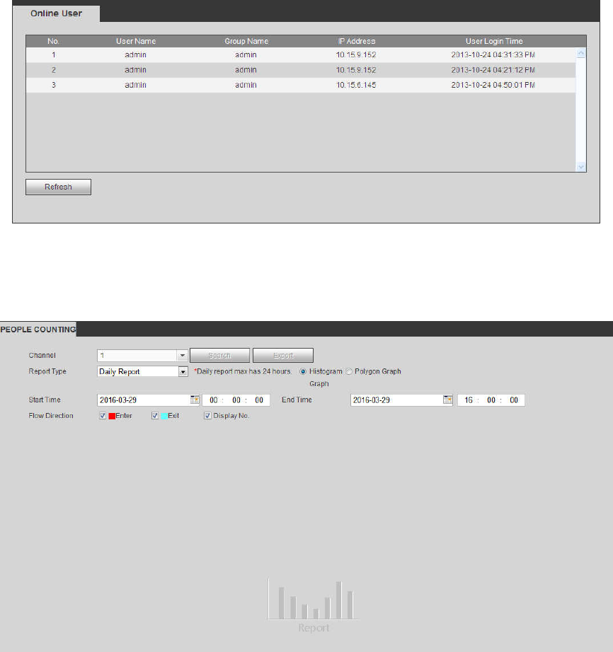
5.12.3 Online User
The online user interface is shown as in Figure 5-152.
335
Figure 5-152
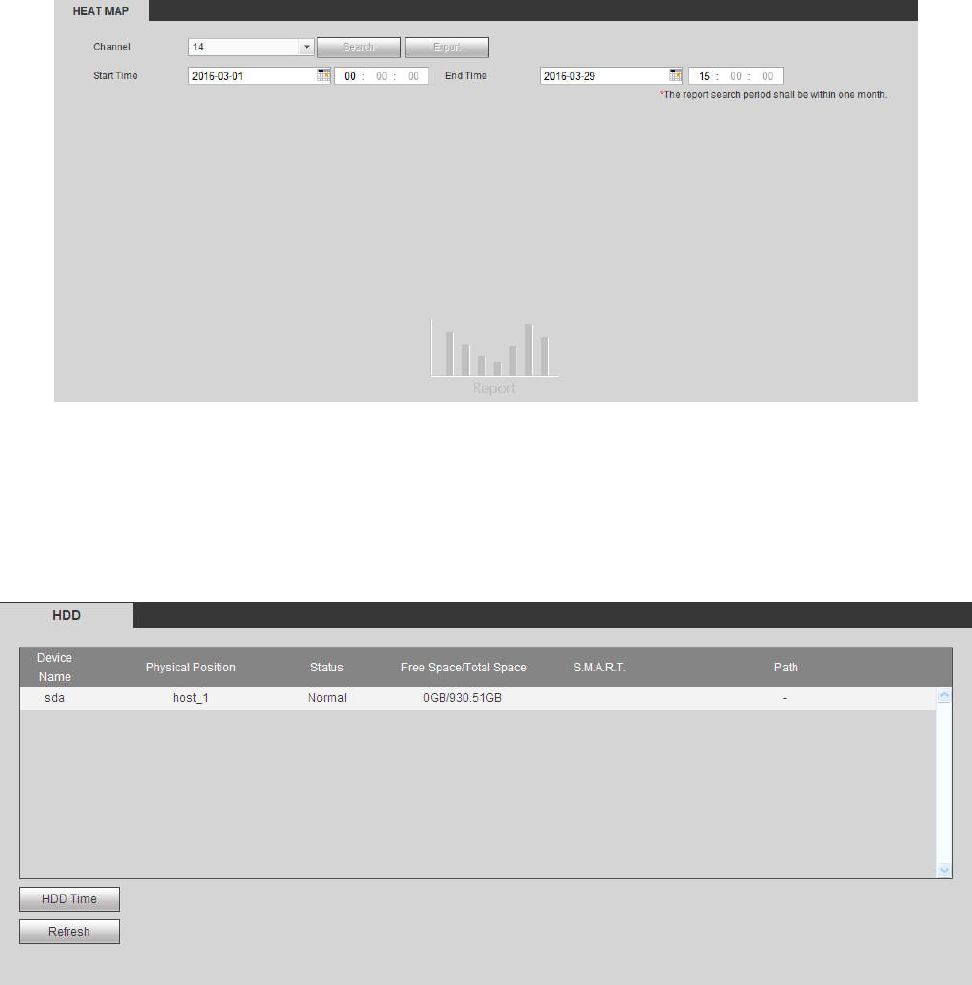
5.12.4 People Counting
From main menu->Info->People counting, the interface is shown as in Figure 5-153.
Figure 5-153
5.12.5 Heat Map
From main menu->Info->Heat Map, the interface is shown as in Figure 5-154.
336
Figure 5-154
5.12.6 HDD
From main menu->Info->HDD, the HDD interface is shown as in Figure 5-155. Here you can view HDD
information.
Figure 5-155
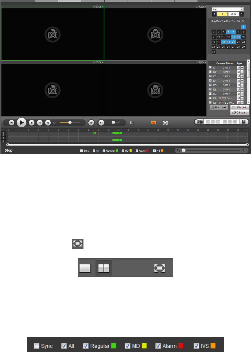
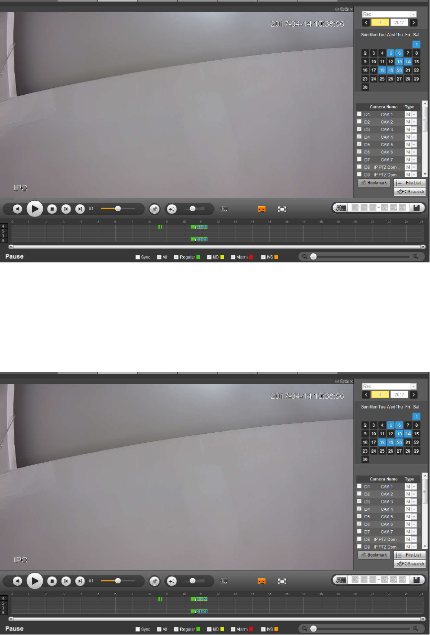
5.13 Playback
Click Playback button, you can see an interface is shown as in Figure 5-156.
337
Figure 5-156
5.13.1 Search Record
Please set record type, record date, window display mode and channel name.
Select Date
You can click the date on the right pane to select the date. The green highlighted date is system current
date and the blue highlighted date means it has record files.
Window Split
Select window split mode. Click to display in full screen. Click ESC button to exit. See Figure 5-157.
Figure 5-157
Select Channel
1~4 means main stream and A1~A4 means sub stream.
Select Record Type
Check the corresponding box to select record type. See Figure 5-158.
Figure 5-158
5.13.2 File List
Click File list button, you can see the corresponding files in the list. See Figure 5-159.
338
Figure 5-159
5.13.3 Playback
Select a file you want to play and then click Play button, system can begin playback. You can select to
playback in full-screen. Please note for one channel, system cannot playback and download at the same
time. You can use the playback control bar to implement various operations such as play, pause, stop,
slow play, fast play and etc. See Figure 5-160.
Figure 5-160
5.13.4 Download
Select the file(s) you want to download and then click download button, you can see an interface shown
as in Figure 5-161. The Download button becomes Stop button and there is a process bar for your
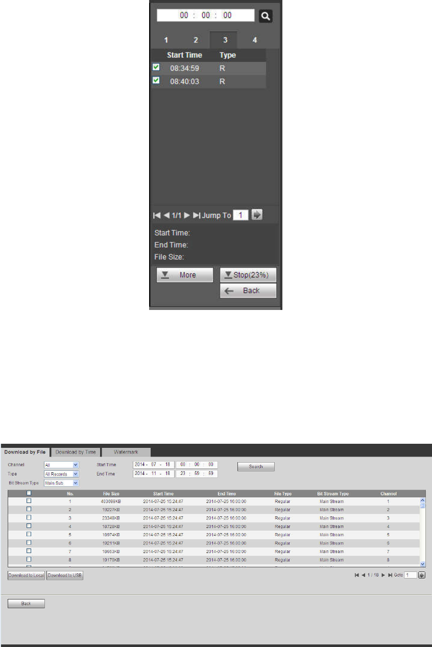
339
reference. Please go to you default file saved path to view the files.
Figure 5-161
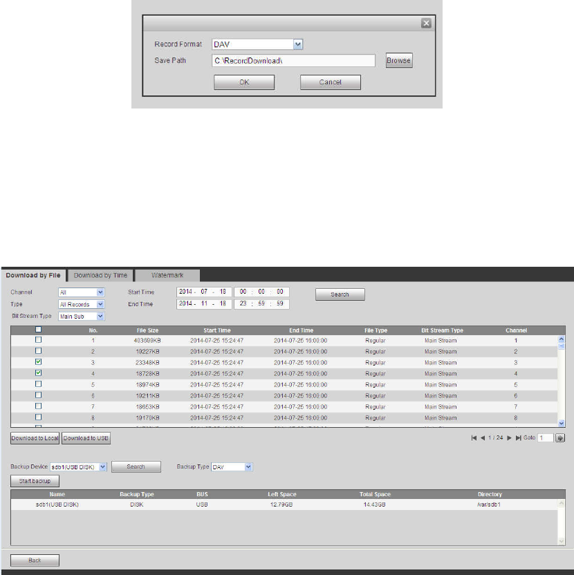
5.13.5 Load more
It is for you to search record or picture. You can select record channel, record type and record time to
download. Or you can use watermark function to verify file.
5.13.5.1 Download By File
Select channel, record type, bit stream type and then input start time and end time. Click Search button,
the download by file interface is shown as in Figure 5-162.
Figure 5-162
Check the file(s) you want to download and there are two options for you to save the file(s).
Download to local
340
Click Download to local, system pops up the following interface for you to set record format and saved
path. See Figure 5-163.
Figure 5-163
You can click OK to download and view the download process. After the download operation, you can see
corresponding dialog box.
Download to USB
Connect the corresponding p peripheral device, and then click Download to USB button, you can see the
following interface. See Figure 5-164.
Figure 5-164
Select Backup device and backup type first and then click Start backup button.
After the download operation, you can see corresponding dialogue box.
5.13.5.2 Download by Time
Select channel, bit stream type, start time and end time.
Click Download to Local button, you can see download by time interface is shown as in Figure 5-165.
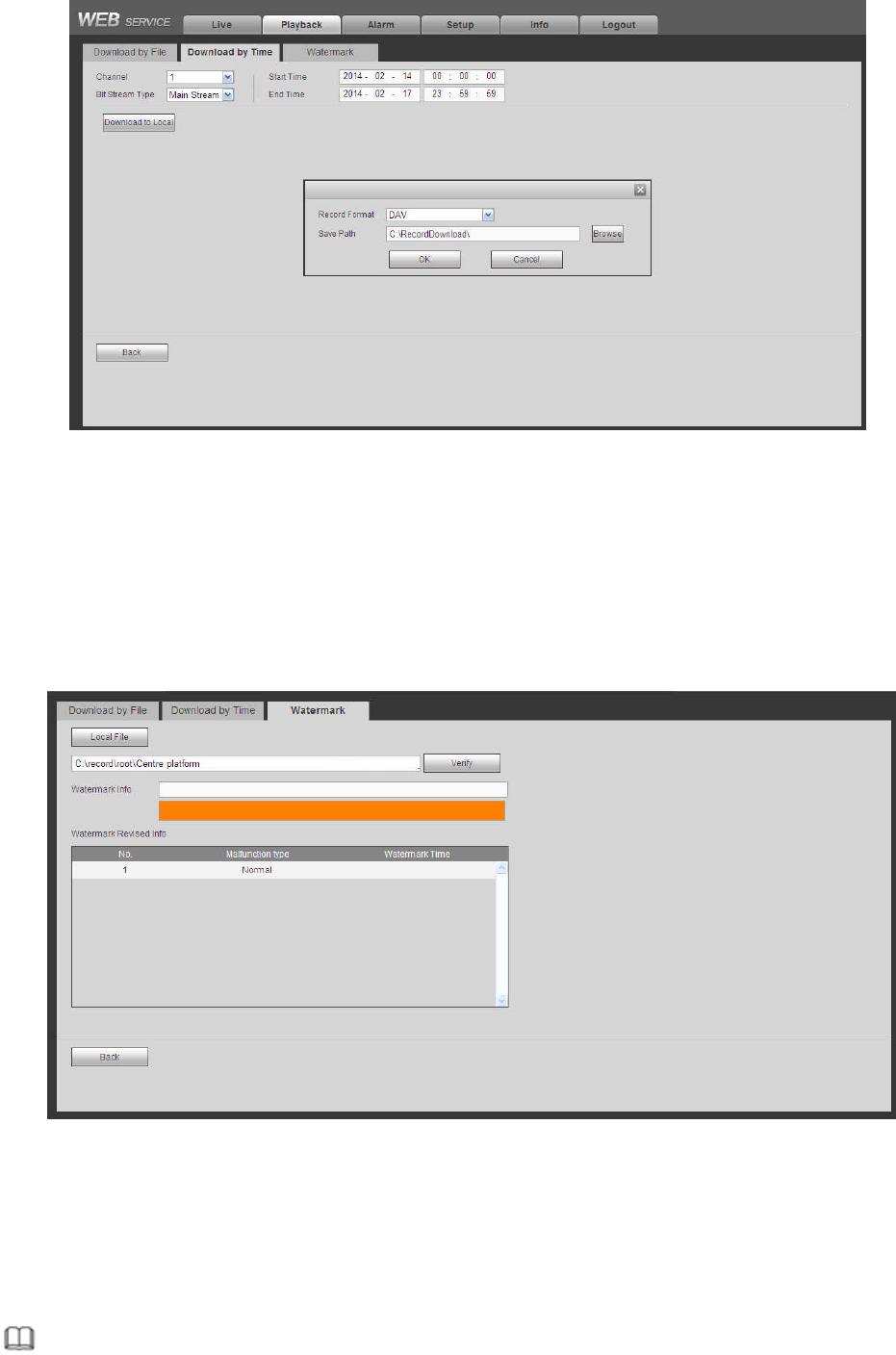
341
Figure 5-165
Set record format and saved path, you can click OK to download and view the download process. After
the download operation, you can see corresponding dialog box.
5.13.5.3 Watermark
Watermark interface is shown as In Figure 5-166. Please select a file and then click Verify button to see
the file has been tampered with or not
Figure 5-166
5.14 Smart Playback
It is to search and playback the IVS file, human face file and plate recognition record.
Note
342
There are two types to realize intelligent analytics function.
Smart network camera supports intelligent functions: Some smart camera supports the intelligent
functions. For NVR, it just displays the intelligent alarm information from the smart network camera
and set or playback the record file.
NVR supports intelligent functions: The connected network camera does not support intelligent video
analytics function. The NVR supports the analytics function.
This function is to playback the intelligent record file of the smart camera.
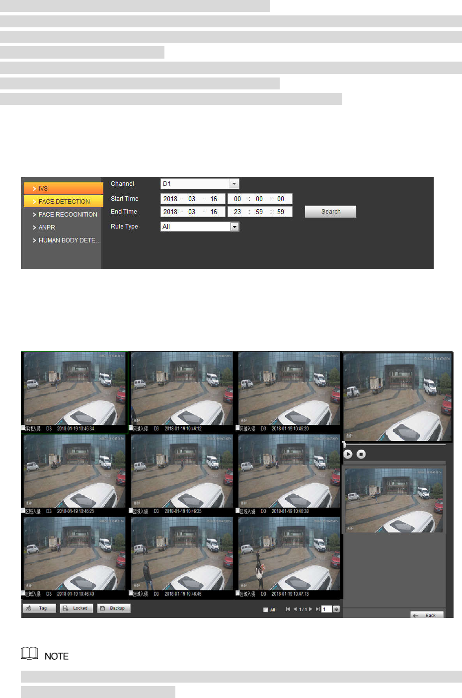
5.14.1 IVS (Behavior Analytics)
It is to search and play back the IVS record files.
Step1 Select Smart Playback-> IVS.
The IVS interface is displayed. See Figure 5-167.
Figure 5-167
Step2 Select the Channel and choose Start Time and End Time.
Step3 Click Search.
The pictures meeting the conditions are displayed. See Figure 5-168.
Figure 5-168
Click Delete on the main interface of Smart Playback to clear the set detect type, channel
number, start time and end time.
Step4 Click the image and you can view the record file.
343
Select a file and then click , you can save current file to peripheral storage
devices.
Select a file and then click , you can lock current file in case it will be
overwritten in the future
Select a file and then click , you can mark the time of the detected event.
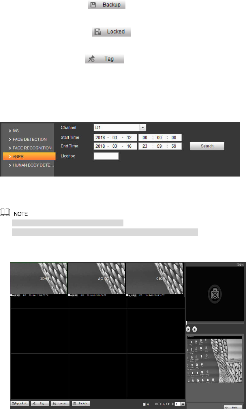
5.14.2 Plate Recognition
It is to search and playback the record file containing the plate number.
Step1 Select Smart Playback-> ANPR.
The ANPR interface is displayd. See Figure 5-169.
Figure 5-169
Step2 Select Channel, Start Time and End Time and set the license number.
The system supports plate fuzzy search.
All plates will be searched by default if the license number is not set.
Step3 Click Search.
The images meeting the conditions are displayed. See Figure 5-170.
344
Figure 5-170
Step4 Click the image and you can view the record file.
Click Export Plate to export the plate information to local.
Select a file and then click , you can save current file to peripheral storage
devices.
Select a file and then click , you can lock current file in case it will be
overwritten in the future
Select a file and then click , you can mark the time of the detected event.
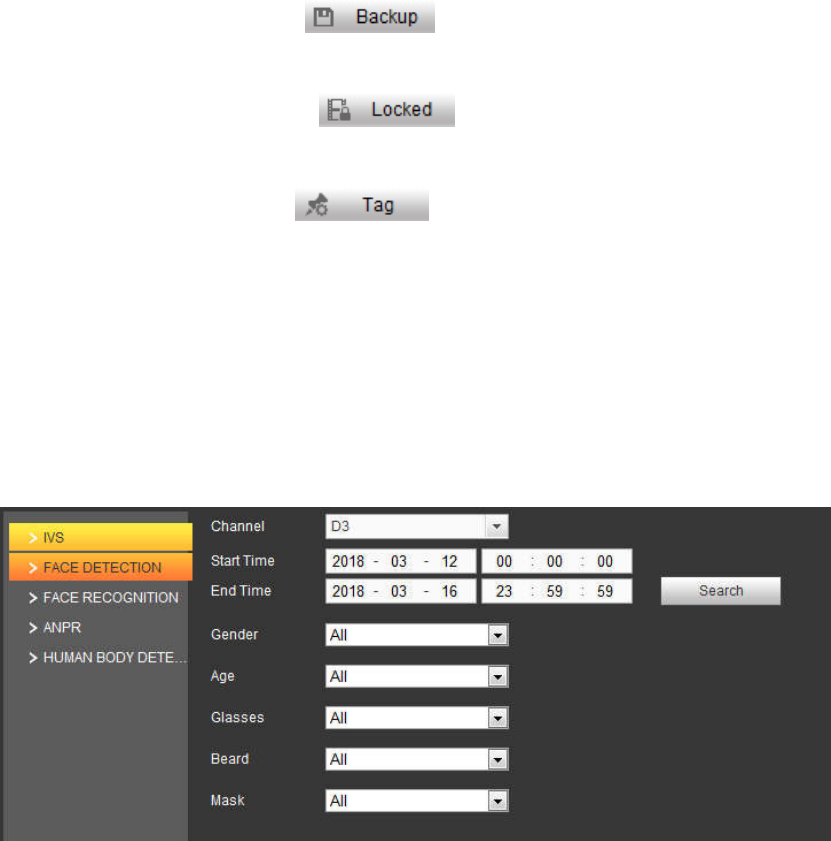
5.14.3 Human Face
System can search the record containing human face and then replay it.
Important
Before you use this function, please make sure current channel has enabled human face detection
function. Please refer to chapter 5.11.3.4 (Setup->Event->Face Detection) for detailed information.
Step1 Select Samrt Playback-> Face Detection.
The Face Detection interface is displayed. See Figure 5-171.
Figure 5-171
Step2 Select Channel, Start Time and End Time and set the filter conditions.
Step3 Click Search.
The images meeting the conditions are displayed. See Figure 5-172.
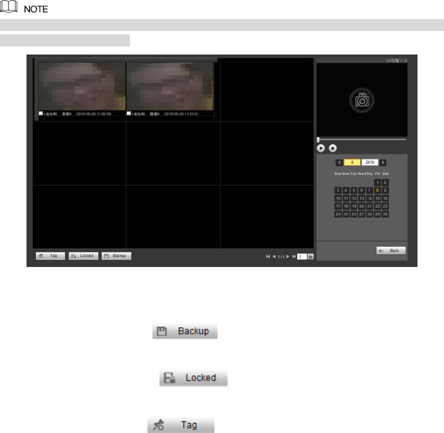
345
The following human faces have been modified for privacy reason. The actually snapshot
images have high definition.
Figure 5-172
Step4 Click the image and you can view the record file.
Select a file and then click , you can save current file to peripheral storage
devices.
Select a file and then click , you can lock current file in case it will be
overwritten in the future
Select a file and then click , you can mark the time of the detected event.
5.15 Alarm
Click alarm function, you can see an interface is shown as Figure 5-173.
Here you can set device alarm type and alarm sound setup (Please make sure you have enabled audio
function of corresponding alarm events.).

346
Figure 5-173
Please refer to the following sheet for detailed information.
Type Parameter Function
Alarm
Type
Video loss System alarms when video loss occurs.
Motion detection
System alarms when motion detection alarm
occurs.
Tampering System alarms when camera is viciously masking.
Disk full System alarms when disk is full.
Disk error System alarms when disk error occurs.
External alarm Alarm input device sends out alarm.
IPC external
alarm
It refers to the on-off signal from the network
camera. It can activate the NVR local activation
operation.
IPC offline alarm
System can generate an alarm when the network
camera and the NVR are disconnected.
Intelligent detect
System alarms when IVS alarm occurs.
Audio detect System alarms when audio detect is abnormal.
Operation
Prompt Check the box here, system can automatically pops
up an alarm icon on the Alarm button in the main
interface when there is an alarm.
Alarm
Sound
Play alarm
sound
System sends out alarm sound when an alarm
occurs. You can specify as you wish.
Sound path Here you can specify alarm sound file.
5.16 Log out
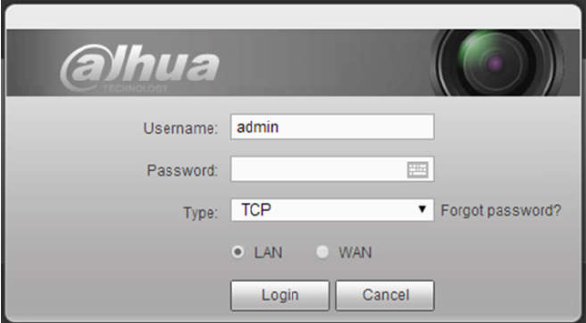
Click log out button, system goes back to log in interface. See Figure 5-174.
You need to input user name and password to login again.
347
Figure 5-174
5.17 Un-install Web Control
You can use web un-install tool “uninstall web.bat” to un-install web control.
Please note, before you un-installation, please close all web pages, otherwise the un-installation
might result in error
348
6 Glossary
DHCP: DHCP (Dynamic Host Configuration Protocol) is a network protocol. It is one of the TCP/IP
protocol cluster. It is principally used to assign temporary IP addresses to computers on a network.
DDNS: DDNS (Dynamic Domain Name Server) is a service that maps Internet domain names to IP
addresses. This service is useful to anyone who wants to operate a server (web server, mail server,
ftp server and etc) connected to the internet with a dynamic IP or to someone who wants to connect
to an office computer or server from a remote location with software.
eSATA: eSATA(External Serial AT) is an interface that provides fast data transfer for external storage
devices. It is the extension specifications of a SATA interface.
GPS: GPS (Global Positioning System) is a satellite system, protected by the US military, safely
orbiting thousands of kilometers above the earth.
PPPoE: PPPoE (Point to Point Protocol over Ethernet) is a specification for connecting multiple
computer users on an Ethernet local area network to a remote site. Now the popular mode is ADSL
and it adopts PPPoE protocol.
Wi-Fi: Wi-Fi is the name of a popular wireless networking technology that uses radio waves to
provide wireless high-speed Internet and network connections. The standard is for wireless local
area networks (WLANs). It is like a common language that all the devices use to communicate to
each other. It is actually IEEE802.11, a family of standard The IEEE (Institute of Electrical and
Electronics Engineers Inc.)
3G: 3G is the wireless network standard. It is called 3G because it is the third generation of cellular
telecom standards. 3G is a faster network for phone and data transmission and speed Is over several
hundred kbps. Now there are four standards: CDMA2000, WCDMA, TD-SCDMA and WiMAX.
Dual-stream: The dual-stream technology adopts high-rate bit stream for local HD storage such as
QCIF/CIF/2CIF/DCIF/4CIF encode and one low-rate bit stream for network transmission such as
QCIF/CIF encode. It can balance the local storage and remote network transmission. The
dual-stream can meet the difference band width requirements of the local transmission and the
remote transmission. In this way, the local transmission using high-bit stream can achieve HD
storage and the network transmission adopting low bit stream suitable for the fluency requirements of
the 3G network such as WCDMA, EVDO, TD-SCDMA..
On-off value: It is the non-consecutive signal sampling and output. It includes remote sampling and
remote output. It has two statuses: 1/0.

349
7 FAQ
Questions Solutions
NVR cannot boot up
properly.
Input power is not correct.
Power connection is not correct.
Power switch button is damaged.
Program upgrade is wrong.
HDD malfunction or something wrong with HDD ribbon.
Seagate DB35.1, DB35.2, SV35 or Maxtor 17-g has compatibility
problem. Please upgrade to the latest version to solve this
problem.
Front panel error.
Main board is damaged.
NVR often automatically
shuts down or stops
running.
Input voltage is not stable or it is too low.
HDD malfunction or something wrong with the ribbon.
Button power is not enough.
Front video signal is not stable.
Working environment is too harsh, too much dust.
Hardware malfunction.
System cannot detect
hard disk.
HDD is broken.
HDD ribbon is damaged.
HDD cable connection is loose.
Main board SATA port is broken.
There is no video output
whether it is one-channel,
multiple-channel or
all-channel output.
Program is not compatible. Please upgrade to the latest version.
Brightness is 0. Please restore factory default setup.
Check your screen saver.
NVR hardware malfunctions.
I cannot search local
records.
HDD ribbon is damaged.
HDD is broken.
Upgraded program is not compatible.
The recorded file has been overwritten.
Record function has been disabled.
Video is distorted when
searching local records.
Video quality setup is too low.
Program read error, bit data is too small. There is mosaic in the full
screen. Please restart the NVR to solve this problem.
HDD data ribbon error.
HDD malfunction.
NVR hardware malfunctions.
Time display is not
correct.
Setup is not correct
Battery contact is not correct or voltage is too low.
Crystal is broken.

350
Questions Solutions
NVR cannot control PTZ.
Front panel PTZ error
PTZ decoder setup, connection or installation is not correct.
Cable connection is not correct.
PTZ setup is not correct.
PTZ decoder and NVR protocol is not compatible.
PTZ decoder and NVR address is not compatible.
When there are several decoders, please add 120 Ohm between
the PTZ decoder A/B cables furthest end to delete the
reverberation or impedance matching. Otherwise the PTZ control
is not stable.
The distance is too far.
I cannot log in client-end
or web.
For Windows 98 or Windows ME user, please update your system
to Windows 2000 sp4. Or you can install client-end software of
lower version. Please note right now, our NVR is not compatible
with Windows VISTA control.
ActiveX control has been disabled.
No dx8.1 or higher. Please upgrade display card driver.
Network connection error.
Network setup error.
Password or user name is invalid.
Client-end is not compatible with NVR program.
There is only mosaic no
video when preview or
playback video file
remotely.
Network fluency is not good.
Client-end resources are limit.
Current user has no right to monitor.
Network connection is
not stable.
Network is not stable.
IP address conflict.
MAC address conflict.
PC or device network card is not good.
Burn error /USB back
error.
Burner and NVR are in the same data cable.
System uses too much CPU resources. Please stop record first
and then begin backup.
Data amount exceeds backup device capacity. It may result in
burner error.
Backup device is not compatible.
Backup device is damaged.
Keyboard cannot control
NVR.
NVR serial port setup is not correct
Address is not correct
When there are several switchers, power supply is not enough.
Transmission distance is too far.

351
Questions Solutions
Alarm signal cannot been
disarmed.
Alarm setup is not correct.
Alarm output has been open manually.
Input device error or connection is not correct.
Some program versions may have this problem. Please upgrade
your system.
Alarm function is null.
Alarm setup is not correct.
Alarm cable connection is not correct.
Alarm input signal is not correct.
There are two loops connect to one alarm device.
Record storage period is
not enough.
Camera quality is too low. Lens is dirty. Camera is installed against
the light. Camera aperture setup is not correct.
HDD capacity is not enough.
HDD is damaged.
Cannot playback the
downloaded file.
There is no media player.
No DXB8.1 or higher graphic acceleration software.
There is no DivX503Bundle.exe control when you play the file
transformed to AVI via media player.
No DivX503Bundle.exe or ffdshow-2004 1012 .exe in Windows XP
OS.
Forgot local menu
operation password or
network password
Please contact your local service engineer or our sales person for
help. We can guide you to solve this problem.
There is no video. The
screen is in black.
IPC IP address is not right.
IPC port number is not right.
IPC account (user name/password) is not right.
IPC is offline.
The displayed video is not
full in the monitor.
Please cheek current resolution setup. If the current setup is
1920*1080, then you need to set the monitor resolution as 1920*1080.
There is no HDMI output. Displayer is not in HDMI mode.
HDMI cable connection is not right.
The video is not fluent
when I view in
multiple-channel mode
from the client-end.
The network bandwidth is not sufficient. The multiple-channel
monitor operation needs at least 100M or higher.
Your PC resources are not sufficient. For 16-ch remote monitor
operation, the PC shall have the following environment:
Quad Core, 2G or higher memory, independent displayer,
display card memory 256M or higher.

352
Questions Solutions
I can not connect to the
IPC
Please make sure the IPC has booted up.
IPC network connection is right and it is online
IPC IP is in the blacklist.
The device has connected to the too many IPC. It cannot transmit
the video.
Check the IPC port value and the time zone is the same as the
NVR.
Make sure current network environment is stable.
After I set the NVR
resolution as 1080P, my
monitor can not display.
Shut down the device and then reboot. When you reboot, please press
the Fn button at the same time and then release after 5 seconds. You
can restore NVR resolution to the default setup.
My admin account has
been changed and I can
not log in.
Use telnet and then input the following command:
cd /mnt/mtd/Config/
rm -rf group
rm -rf password
Reboot the device to restore the default password.
After I login the Web , I
can not find the remote
interface to add the IPC.
Please clear the Web controls and load again.
There is IP and gateway, I
can access the internet
via the router. But I can
not access the internet
after I reboot the NVR.
Please use command PING to check you can connect to the gateway
or not. Use telnet to access and then use command “ifconfig –a” to
check device IP address. If you see the subnet mask and the gateway
has changed after the reboot. Please upgrade the applications and set
again.
I use the VGA montior.I
want to know if I use the
multple-window mode, I
see the video from the
main stream or the sub
stream?
For 32-channel series product, the 9/16-window is using the sub
stream.
For 4/8/16 series product, system is using the main stream no
matter you are in what display mode.
Daily Maintenance
Please use the brush to clean the board, socket connector and the chassis regularly.
The device shall be soundly earthed in case there is audio/video disturbance. Keep the device away
from the static voltage or induced voltage.
Please unplug the power cable before you remove the audio/video signal cable, RS232 or RS485
cable.
Do not connect the TV to the local video output port (VOUT).It may result in video output circuit.
Always shut down the device properly. Please use the shutdown function in the menu, or you can
press the power button in the rear pane for at least three seconds to shut down the device.
353
Otherwise it may result in HDD malfunction.
Please make sure the device is away from the direct sunlight or other heating sources. Please keep
the sound ventilation.
Please check and maintain the device regularly.
354
8 Appendix A HDD Capacity Calculation
Calculate total capacity needed by each device according to video recording (video recording type and
video file storage time).
Step 1: According to Formula (1) to calculate storage capacity i
q that is the capacity of each channel
needed for each hour, unit Mbyte.
102436008 ii dq (1)
In the formula: i
d means the bit rate, unit Kbit/s
Step 2: After video time requirement is confirmed, according to Formula (2) to calculate the storage
capacity i
m, which is storage of each channel needed unit Mbyte.
i
m = i
q×i
h×i
D (2)
In the formula:
i
h means the recording time for each day (hour)
i
D means number of days for which the video shall be kept
Step 3: According to Formula (3) to calculate total capacity (accumulation) T
q
that is needed for all
channels in the device during scheduled video recording.
c
i
iT mq
1
(3)
In the formula:
c
means total number of channels in one device
Step 4: According to Formula (4) to calculate total capacity (accumulation) T
q
that is needed for all
channels in device during alarm video recording (including motion detection).
c
i
iT mq
1
×a% (4)
In the formula:a% means alarm occurrence rate

355
9 Appendix B Compatible Network Camera List
Please note all the models in the following list for reference only. For those products not included in the
list, please contact your local retailer or technical supporting engineer for detailed information.
Manufact
ure
Model Version Video Encode Audio/Vid
eo
Protocol
AXIS P1346 5.40.9.2 H264 √ ONVIF/Private
P3344/P3344-
E
5.40.9.2 H264 √ ONVIF/Private
P5512 - H264 √ ONVIF/Private
Q1604 5.40.3.2 H264 √ ONVIF/Private
Q1604-E 5.40.9 H264 √ ONVIF/Private
Q6034E - H264 √ ONVIF/Private
Q6035 5.40.9 H264 √ ONVIF/Private
Q1755 - H264 √ ONVIF/Private
M7001 - H264 √ Private
M3204 5.40.9.2 H264 √ Private
P3367 HEAD LFP4_0
130220
H264 √ ONVIF
P5532-P HEAD LFP4_0
130220
H264 √ ONVIF
ACTi ACM-3511 A1D-220-V3.12
.15-AC
MPEG4 √ Private
ACM-8221 A1D-220-V3.13
.16-AC
MPEG4 √ Private
Arecont AV1115 65246 H264 √ Private
AV10005DN 65197 H264 √ Private
AV2115DN 65246 H264 √ Private
AV2515DN 65199 H264 √ Private
AV2815 65197 H264 √ Private
AV5115DN 65246 H264 √ Private
AV8185DN 65197 H264 √ Private
Bosch NBN-921-P - H264 √ ONVIF
NBC-455-12P
- H264 √ ONVIF
VG5-825 9500453 H264 √ ONVIF
NBN-832 66500500 H264 √ ONVIF
VEZ-211-IWT
EIVA
- H264 √ ONVIF
NBC-255-P 15500152 H264 √ ONVIF
VIP-X1XF - H264 √ ONVIF
Brikcom B0100 - H264 √ ONVIF
D100 - H264 √ ONVIF
GE-100-CB - H264 √ ONVIF
FB-100A v1.0.3.9 H264 √ ONVIF
FD-100A v1.0.3.3 H264 √ ONVIF

356
Manufact
ure
Model Version Video Encode Audio/Vid
eo
Protocol
Cannon VB-M400 - H264 √ Private
CNB MPix2.0DIR XNETM112011
1229
H264 √ ONVIF
VIPBL1.3MIR
VF
XNETM210011
1229
H264 √ ONVIF
IGC-2050F XNETM210011
1229
H264 √ ONVIF
CP PLUS CP-NC9-K 6.E.2.7776 H264 √ ONVIF/Private
CP-NC9W-K 6.E.2.7776 H264 √ Private
CP-ND10-R cp20111129AN
S
H264 √ ONVIF
CP-ND20-R cp20111129AN
S
H264 √ ONVIF
CP-NS12W-C
R
cp20110808NS
H264 √ ONVIF
VS201 cp20111129NS H264 √ ONVIF
CP-NB20-R cp20110808BN
S
H264 √ ONVIF
CP-NT20VL3-
R
cp20110808BN
S
H264 √ ONVIF
CP-NS36W-A
R
cp20110808NS
H264 √ ONVIF
CP-ND20VL2-
R
cp20110808BN
S
H264 √ ONVIF
CP-RNP-1820
cp20120821NS
A
H264 √ Private
CP-RNC-TP2
0FL3C
cp20120821NS
A
H264 √ Private
CP-RNP-12D cp20120828AN
S
H264 √ Private
CP-RNC-DV1
0
cp20120821NS
A
H264 √ Private
CP-RNC-DP2
0FL2C
cp20120821NS
A
H264 √ Private
Dynacolor
ICS-13 d20120214NS H264 √ ONVIF/Private
ICS-20W vt20111123NSA
H264 √ ONVIF/Private
NA222 - H264 √ ONVIF
MPC-IPVD-03
13
k20111208ANS
H264 √ ONVIF/Private
MPC-IPVD-03
13AF
k20111208BNS
H264 √ ONVIF/Private
Honeywell
HIDC-1100PT
h.2.2.1824 H264 √ ONVIF
HIDC-1100P h.2.2.1824 H264 √ ONVIF

357
Manufact
ure
Model Version Video Encode Audio/Vid
eo
Protocol
HIDC-0100P h.2.2.1824 H264 √ ONVIF
HIDC-1300V 2.0.0.21 H264 √ ONVIF
HICC-1300W 2.0.1.7 H264 √ ONVIF
HICC-2300 2.0.0.21 H264 √ ONVIF
HDZ20HDX H20130114NS
A
H264 √ ONVIF
LG LW342-FP - H264 √ Private
LNB5100 - H264 √ ONVIF
Imatek KNC-B5000 - H264 √ Private
KNC-B5162 - H264 √ Private
KNC-B2161 - H264 √ Private
Panasonic
NP240/CH - MPEG4 √ Private
WV-NP502 - MPEG4 √ Private
WV-SP102H 1.41 H264 √ ONVIF/Private
WV-SP105H - H264 √ ONVIF/Private
WV-SP302H 1.41 H264、MPEG4 √ ONVIF/Private
WV-SP306H 1.4 H264、MPEG4 √ ONVIF/Private
WV-SP508H - H264、MPEG4 √ ONVIF/Private
WV-SP509H - H264、MPEG4 √ ONVIF/Private
WV-SF332H 1.41 H264、MPEG4 √ ONVIF/Private
WV-SW316H 1.41 H264、MPEG4 √ ONVIF/Private
WV-SW355H 1.41 H264、MPEG4 √ ONVIF/Private
WV-SW352H - H264、MPEG4 √ ONVIF/Private
WV-SW152E 1.03 H264、MPEG4 √ ONVIF/Private
WV-SW558H - H264、MPEG4 √ ONVIF/Private
WV-SW559H - H264、MPEG4 √ ONVIF/Private
WV-SP105H 1.03 H264、MPEG4 √ ONVIF/Private
WV-SW155E 1.03 H264、MPEG4 √ ONVIF/Private
WV-SF336H 1.44 H264、MPEG4 √ ONVIF/Private
WV-SF332H 1.41 H264、MPEG4 √ ONVIF/Private
WV-SF132E 1.03 H264、MPEG4 √ ONVIF/Private
WV-SF135E 1.03 H264、MPEG4 √ ONVIF/Private
WV-SF346H 1.41 H264、MPEG4 √ ONVIF/Private
WV-SF342H 1.41 H264、MPEG4 √ ONVIF/Private
WV-SC385H 1.08 H264、MPEG4 √ ONVIF/Private
WV-SC386H 1.08 H264、MPEG4 √ ONVIF/Private
WV-SP539 1.66 H264、MPEG4 √ ONVIF
DG-SC385 1.66 H264、MPEG4 √ ONVIF
PELCO IXSOLW 1.8.1-20110912
-1.9082-A1.661
7
H264 √ Private
IDE20DN 1.7.41.9111-O3
.6725
H264 √ Private

358
Manufact
ure
Model Version Video Encode Audio/Vid
eo
Protocol
D5118 1.7.8.9310-A1.
5288
H264 √ Private
IM10C10 1.6.13.9261-O2
.4657
H264 √ Private
DD4N-X 01.02.0015 MPEG4 √ Private
DD423-X 01.02.0006 MPEG4 √ Private
D5220 1.8.3-FC2-2012
0614-1.9320-A
1.8035
H264 √ Private
Samsung SNB-3000P 2.41 H264、MPEG4 √ ONVIF/Private
SNP-3120 1.22_110120_1
H264、MPEG4 √ ONVIF/Private
SNP-3370 1.21_110318 MPEG4 √ Private
SNB-5000 2.10_111227 H264、MPEG4 √ ONVIF/Private
SND-5080 - H264、MPEG4 √ Private
SNZ-5200 1.02_110512 H264、MPEG4 √ ONVIF/Private
SNP-5200 1.04_110825 H264、MPEG4 √ ONVIF/Private
SNB-7000 1.10_110819 H264 √ ONVIF/Private
SNB-6004 V1.0.0 H264 √ ONVIF
Sony SNC-DH110 1.50.00 H264 √ ONVIF/Private
SNC-CH120 1.50.00 H264 √ ONVIF/Private
SNC-CH135 1.73.01 H264 √ ONVIF/Private
SNC-CH140 1.50.00 H264 √ ONVIF/Private
SNC-CH210 1.73.00 H264 √ ONVIF/Private
SNC-DH210 1.73.00 H264 √ ONVIF/Private
SNC-DH240 1.50.00 H264 √ ONVIF/Private
SNC-DH240-T
1.73.01 H264 √ ONVIF/Private
SNC-CH260 1.74.01 H264 √ ONVIF/Private
SNC-CH280 1.73.01 H264 √ ONVIF/Private
SNC-RH-124 1.73.00 H264 √ ONVIF/Private
SNC-RS46P 1.73.00 H264 √ ONVIF/Private
SNC-ER550 1.74.01 H264 √ ONVIF/Private
SNC-ER580 1.74.01 H264 √ ONVIF/Private
SNC-ER580 1.78.00 H264 √ ONVIF
SNC-VM631 1.4.0 H264 √ ONVIF
WV-SP306 1.61.00 H264、MPEG4 √ SDK
WV-SP306 1.61.00 H264 √ ONVIF
SNC-VB600 1.5.0 H264 √ Private
SNC-VM600 1.5.0 H264 √ Private
SNC-VB630 1.5.0 H264 √ Private
SNC-VM630 1.5.0 H264 √ Private
SANYO VCC-HDN400
0PC
- H264 √ ONVIF
359
ZHEJIANG DAHUA VISION TECHNOLOGY CO.,LTD.
Address:No.1199, Bin'an Road, Binjiang District, Hangzhou, P.R. China
Postcode: 310053
Tel: +86-571-87688883
Fax: +86-571-87688815
Email:overseas@dahuatech.com
Website: www.dahuasecurity.com