Zhejiang Dahua Vision Technology DHNVR41WSX Network Video Recorder User Manual 1
Zhejiang Dahua Vision Technology Co., Ltd Network Video Recorder Users Manual 1
Contents
- 1. Users Manual-1
- 2. Users Manual-2
Users Manual-1

Dahua Network Video Recorder User’s Manual
V 2.4.3

i
Table of Contents
1 Features and Specifications ............................................................................................................... 1
1.1 Overview ........................................................................................................................................ 1
1.2 Features ......................................................................................................................................... 1
1.3 Specifications ................................................................................................................................ 2
1.3.1 NVR100/100-P Series .......................................................................................................... 2
1.3.2 NVR11/11-P Series ............................................................................................................... 4
1.3.3 NVR21-S2/NVR21-P-S2/NVR21-8P-S2 Series ................................................................ 7
1.3.4 NVR11H/11H-P Series ......................................................................................................... 9
1.3.5 NVR11HS Series ................................................................................................................. 11
1.3.6 NVR21HS-S2/21HS-P-S2/21HS-8P-S2 Series .............................................................. 13
1.3.7 NVR41HS-W-S2 Series...................................................................................................... 15
1.3.8 NVR41/41-P/41-8P/41-W Series ...................................................................................... 16
1.3.9 NVR41H/41H-P/41H-8P Series ........................................................................................ 18
1.3.10 NVR22-S2/22-P-S2/22-8P-S2 Series............................................................................... 20
1.3.11 NVR42N Series ................................................................................................................... 21
1.3.12 NVR42/42-P/42-8P Series ................................................................................................. 23
1.3.13 NVR42-16P Series .............................................................................................................. 25
1.3.14 NVR42-4K/42-8P-4K Series .............................................................................................. 27
1.3.15 NVR52-4KS2/52-8P-4KS2/52-16P-4KS2 Series ........................................................... 29
1.3.16 NVR44/44-8P/44-16P Series ............................................................................................. 30
1.3.17 NVR44-4K Series ................................................................................................................ 32
1.3.18 NVR54-4KS2/54-16P-4KS2 Series .................................................................................. 34
1.3.19 NVR48-4K Series ................................................................................................................ 35
1.3.20 NVR58-4KS2/58-16P-4KS2 Series .................................................................................. 37
1.3.21 NVR48/48-16P Series ........................................................................................................ 39
1.3.22 NVR72/72-8P Series ........................................................................................................... 40
1.3.23 NVR74/74-8P/74-16P Series ............................................................................................. 42
1.3.24 NVR78/78-16P/78-RH Series ............................................................................................ 44
1.3.25 NVR70/70-R Series ............................................................................................................. 46
1.3.26 NVR42V-8P Series ............................................................................................................. 48
2 Front Panel and Rear Panel ............................................................................................................. 50
2.1 Front Panel .................................................................................................................................. 50
2.1.1 NVR11/11-P/41/41-P/41-W/21-S2/21-P-S2/21-8P-S2 Series ...................................... 50
2.1.2 NVR11H/11H-P/41H/41H-P/41H-8P Series .................................................................... 50
2.1.3 NVR11HS Series ................................................................................................................. 51
2.1.4 NVR41HS-W-S2 Series...................................................................................................... 51
2.1.5 NVR41-8P Series ................................................................................................................ 52
2.1.6 NVR42/42-P/42-8P/72/72-8P Series ................................................................................ 53
2.1.7 NVR21HS-S2/21HS-P-S2/21HS-8P-S2/22-S2/22-P-S2/22-8P-S2 Series ................. 55
2.1.8
NVR42-16P/42N/42-4K/42-8P-4K/44-4K/48-4K/52-4KS2/52-8P-4KS2/52-16P-4KS2/
54-4KS2/58-4KS2 Series .................................................................................................................. 55
2.1.9 NVR44/44-8P/44-16P/74/74-8P/74-16P Series .............................................................. 56

ii
2.1.10 NVR48/48-16P/78/78-16P Series ..................................................................................... 58
2.1.11 NVR78-RH Series ............................................................................................................... 60
2.1.12 NVR70/70-R Series ............................................................................................................. 62
2.1.13 NVR42V-8P Series .............................................................................................................. 64
2.2 Rear Panel .................................................................................................................................. 65
2.2.1 NVR100/100-P Series ........................................................................................................ 65
2.2.2 NVR11/11-P Series ............................................................................................................. 66
2.2.3 NVR41/41-P/41-8P/41-W Series ...................................................................................... 67
2.2.4 NVR21-S2/21-P-S2/21-8P-S2 Series............................................................................... 69
2.2.5 NVR11H/11H-P/41H/41H-P/41H-8P Series .................................................................... 71
2.2.6 NVR11HS Series ................................................................................................................. 72
2.2.7 NVR21HS-S2/21HS-P-S2/21HS-8P-S2 Series .............................................................. 73
2.2.8 NVR41HS-W-S2 Series ...................................................................................................... 74
2.2.9 NVR22-S2/22-P-S2/22-8P-S2 Series............................................................................... 75
2.2.10 NVR42/42N/42-P/42-8P/42-16P Series ........................................................................... 76
2.2.11 NVR42-4K/52-4KS2/52-8P-4KS2/52-16P-4KS2 Series ................................................ 79
2.2.12 NVR42-8P-4K Series .......................................................................................................... 80
2.2.13 NVR44/44-8P/44-16P Series ............................................................................................. 82
2.2.14 NVR44-4K/48-4K/54-4KS2/58-4KS2/54-16P-4KS2/58-16P-4KS2 Series ................. 84
2.2.15 NVR48/48-16P Series ........................................................................................................ 86
2.2.16 NVR72 Series ...................................................................................................................... 88
2.2.17 NVR72-8P Series ................................................................................................................ 89
2.2.18 NVR74 Series ...................................................................................................................... 91
2.2.19 NVR74-8P/74-16P Series .................................................................................................. 93
2.2.20 NVR78 Series ...................................................................................................................... 95
2.2.21 NVR78-16P Series .............................................................................................................. 97
2.2.22 NVR78-RH Series ............................................................................................................... 99
2.2.23 NVR70 Series .................................................................................................................... 100
2.2.24 NVR70-R Series ................................................................................................................ 102
2.2.25 NVR42V-8P Series ............................................................................................................ 104
2.3 Alarm Connection ..................................................................................................................... 106
2.3.1 Alarm Port ........................................................................................................................... 106
2.3.2 Alarm input port ................................................................................................................. 107
2.3.3 Alarm input and output port .............................................................................................. 107
2.3.4 Alarm relay specifications ................................................................................................ 108
2.4 Bidirectional talk ....................................................................................................................... 108
2.4.1 Device-end to PC-end ...................................................................................................... 108
2.4.2 PC-end to the device-end ................................................................................................ 109
2.5 Mouse Operation ...................................................................................................................... 109
2.6 Remote Control ........................................................................................................................ 110
3 Device Installation ............................................................................................................................ 113
3.1 Check Unpacked NVR ............................................................................................................. 113
3.2 About Front Panel and Rear Panel........................................................................................ 113
3.3 HDD Installation ........................................................................................................................ 113
3.3.1 NVR100/100-P Series ...................................................................................................... 113

iii
3.3.2 NVR11/11-P/41/41-P/41-8P/41-W/21-S2/21-P-S2/21-8P-S2 Series ........................ 114
3.3.3 NVR11H/11H-P/41H/41H-P/41H-8P/11HS/21HS-S2/21HS-P-S2/21HS-8P-S2/
41HS-W-S2 Series ........................................................................................................................... 115
3.3.4
NVR42/42N/42-P/42-8P/42-16P/72/72-8P/42-4K/42-8P-4K/52-4KS2/52-8P-4KS2/52
-16P-4KS2/22-S2/22-P-S2/22-8P-S2 Series ............................................................................... 116
3.3.5 NVR44/44-8P/44-16P/74/74-8P/74-16P/44-4K/54-4KS2/54-16P-4KS2 Series ...... 116
3.3.6 NVR48/48-16P/NVR78/78-16P/48-4K/58-4KS2/58-16P-4KS2 Series ..................... 117
3.3.7 NVR78-RH Series ............................................................................................................. 118
3.3.8 NVR70/70-R Series ........................................................................................................... 119
3.3.9 NVR42V-8P Series ........................................................................................................... 120
3.4 CD-ROM Installation ................................................................................................................ 120
3.5 Connection Sample .................................................................................................................. 122
3.5.1 NVR100/NVR100-P Series .............................................................................................. 122
3.5.2 NVR11/11-P/41/41-P/41-8P/41-W/21-S2/21-P-S2/21-8P-S2 Series ........................ 122
3.5.3 NVR11H/11H-P/41H/41H-P/41H-8P Series .................................................................. 123
3.5.4 NVR11HS//41HS-W-S2 Series ....................................................................................... 124
3.5.5 NVR41HS-W-S2 Series.................................................................................................... 125
3.5.6 NVR21HS-S2/21HS-P-S2/21HS-8P-S2 Series ............................................................ 126
3.5.7 NVR22-S2/22-P-S2/22-8P-S2 Series............................................................................. 127
3.5.8 NVR42N Series ................................................................................................................. 128
3.5.9 NVR42/42-P/42-8P/42-16P/52-4KS2/52-8P-4KS2/52-16P-4KS2 Series ................. 129
3.5.10 NVR42-4K Series .............................................................................................................. 129
3.5.11 NVR42-8P-4K Series ........................................................................................................ 130
3.5.12 NVR44-4K/48-4K/54-4KS2/54-16P-4KS2/58-4KS2/58-16P-4KS2 Series ............... 130
3.5.13 NVR44/44-8P/44-16P Series ........................................................................................... 131
3.5.14 NVR48/48-16P Series ...................................................................................................... 132
3.5.15 NVR72 Series .................................................................................................................... 133
3.5.16 NVR72-8P Series .............................................................................................................. 133
3.5.17 NVR74 Series .................................................................................................................... 134
3.5.18 NVR74-8P/74-16P Series ................................................................................................ 135
3.5.19 NVR78 Series .................................................................................................................... 136
3.5.20 NVR78-16P Series ............................................................................................................ 137
3.5.21 NVR78-RH Series ............................................................................................................. 138
3.5.22 NVR70 Series .................................................................................................................... 139
3.5.23 NVR70-R Series ................................................................................................................ 140
3.5.24 NVR42V-8P Series ........................................................................................................... 141
4 Local Basic Operation ..................................................................................................................... 143
4.1 Boot up and Shutdown ............................................................................................................ 143
4.1.1 Boot up ................................................................................................................................ 143
4.1.2 Shutdown ............................................................................................................................ 143
4.2 Change/Reset Password ........................................................................................................ 143
4.2.1 Change Password ............................................................................................................. 143
4.2.2 Reset Password ................................................................................................................. 144
4.3 Startup Wizard .......................................................................................................................... 145
4.4 Navigation Bar .......................................................................................................................... 149

iv
4.4.1 Main Menu .......................................................................................................................... 150
4.4.2 Dual-screen operation ...................................................................................................... 150
4.4.3 Output Screen .................................................................................................................... 150
4.4.4 Tour ...................................................................................................................................... 150
4.4.5 PTZ ...................................................................................................................................... 150
4.4.6 Color .................................................................................................................................... 150
4.4.7 Search ................................................................................................................................. 150
4.4.8 Alarm Status ....................................................................................................................... 150
4.4.9 Channel Info ....................................................................................................................... 151
4.4.10 Registration ........................................................................................................................ 151
4.4.11 Network ............................................................................................................................... 151
4.4.12 HDD Manager .................................................................................................................... 151
4.4.13 USB Manager..................................................................................................................... 151
4.5 Smart Add .................................................................................................................................. 151
4.6 Camera ...................................................................................................................................... 155
4.6.1 Registration ........................................................................................................................ 155
4.6.2 Short-Cut Menu ................................................................................................................. 157
4.6.3 Image .................................................................................................................................. 157
4.6.4 Channel Name ................................................................................................................... 159
4.6.5 Upgrade .............................................................................................................................. 160
4.6.6 UPNP .................................................................................................................................. 160
4.6.7 Built-in Switch Setup ......................................................................................................... 161
4.7 Preview ...................................................................................................................................... 161
4.7.1 Preview ............................................................................................................................... 161
4.7.2 Preview control interface .................................................................................................. 162
4.7.3 Right Click Menu ............................................................................................................... 163
4.7.4 Preview Display Effect Setup .......................................................................................... 164
4.7.4.1 Video Color ................................................................................................................ 164
4.7.4.2 Display ....................................................................................................................... 166
4.7.4.3 TV adjust .................................................................................................................... 167
4.7.5 Preview Tour Parameters ................................................................................................ 167
4.8 Fish eye (Optional) ................................................................................................................... 168
4.8.1 Fish eye de-warp during preview interface .................................................................... 168
4.8.2 Fish eye de-warp during playback .................................................................................. 171
4.9 PTZ ............................................................................................................................................. 171
4.9.1 PTZ Settings....................................................................................................................... 171
4.9.2 PTZ Control ........................................................................................................................ 172
4.9.2.1 PTZ Function Setup ................................................................................................. 174
4.9.2.2 Call PTZ Function ..................................................................................................... 177
4.10 Record and Snapshot .............................................................................................................. 178
4.10.1 Encode ................................................................................................................................ 178
4.10.1.1 Encode ....................................................................................................................... 178
4.10.1.2 Overlay ....................................................................................................................... 179
4.10.1.3 Snapshot .................................................................................................................... 180
4.10.2 Schedule ............................................................................................................................. 181
4.10.2.1 Schedule Record ...................................................................................................... 181

v
4.10.2.2 Schedule Snapshot .................................................................................................. 184
4.10.3 Motion detect record/snapshot ........................................................................................ 186
4.10.3.1 Motion detect record ................................................................................................ 186
4.10.3.2 Motion Detect Snapshot .......................................................................................... 188
4.10.4 Alarm Record/Snapshot ................................................................................................... 189
4.10.4.1 Alarm Record ............................................................................................................ 189
4.10.4.2 Alarm Snapshot ........................................................................................................ 190
4.10.5 Manual Record/Snapshot ................................................................................................. 191
4.10.5.1 Manual Record ......................................................................................................... 191
4.10.5.2 Manual Snapshot...................................................................................................... 192
4.10.6 Holiday Record/Snapshot ................................................................................................ 192
4.10.6.1 Holiday Record ......................................................................................................... 192
4.10.6.2 Holiday Snapshot ..................................................................................................... 194
4.10.7 Other Record/Snapshot .................................................................................................... 194
4.11 Playback and Search ............................................................................................................... 194
4.11.1 Real-time Playback ........................................................................................................... 194
4.11.2 Search Interface ................................................................................................................ 194
4.11.2.1 Smart Search ............................................................................................................ 199
4.11.2.2 Accurate playback by time ...................................................................................... 199
4.11.2.3 Mark Playback .......................................................................................................... 200
4.11.3 Picture Playback ................................................................................................................ 201
4.12 Backup ....................................................................................................................................... 202
4.12.1 File Backup ......................................................................................................................... 202
4.12.2 Import/Export ...................................................................................................................... 203
4.12.3 Backup Log......................................................................................................................... 204
4.12.4 USB Device Auto Pop-up ................................................................................................. 205
4.13 Alarm .......................................................................................................................................... 206
4.13.1 Detect Alarm....................................................................................................................... 206
4.13.1.1 Motion Detect ............................................................................................................ 206
4.13.1.2 Tampering .................................................................................................................. 210
4.13.1.3 Video Loss ................................................................................................................. 211
4.13.2 IVS (Optional)..................................................................................................................... 212
4.13.2.1 Tripwire (Optional) .............................................................................................. 212
4.13.2.2 Intrusion (Cross warning zone) (Optional)...................................................... 216
4.13.2.3 Object Detect (Optional) .................................................................................... 218
4.13.2.4 Scene Change (Optional) ................................................................................. 219
4.13.3 Face Detect (Optional)...................................................................................................... 220
4.13.4 Audio Detect (Optional) .................................................................................................... 220
4.13.5 Alarm output ....................................................................................................................... 221
4.13.6 Alarm Setup ........................................................................................................................ 222
4.13.7 Abnormality......................................................................................................................... 227
4.14 Network ...................................................................................................................................... 229
4.14.1.1 TCP/IP ........................................................................................................................ 229
4.14.1.2 Connection ................................................................................................................ 231
4.14.1.3 WIFI AP ...................................................................................................................... 232
4.14.1.3.1 WIFI AP .................................................................................................................. 232

vi
4.14.1.3.2 Advanced ................................................................................................................ 233
4.14.1.4 WIFI ............................................................................................................................ 234
4.14.1.5 3G ............................................................................................................................... 235
4.14.1.6 PPPoE ........................................................................................................................ 236
4.14.1.7 DDNS ......................................................................................................................... 237
4.14.1.8 UPnP .......................................................................................................................... 239
4.14.1.9 IP Filter ....................................................................................................................... 240
4.14.1.10 Email .......................................................................................................................... 242
4.14.1.11 FTP ............................................................................................................................. 243
4.14.1.12 SNMP ........................................................................................................................ 245
4.14.1.13 Multicast .................................................................................................................... 245
4.14.1.14 Alarm Centre ............................................................................................................ 247
4.14.1.15 Auto register ............................................................................................................. 247
4.14.1.16 P2P ............................................................................................................................ 248
4.14.1.17 Easy Space ............................................................................................................... 250
4.14.1.18 SWITCH .................................................................................................................... 251
4.14.2 Network Test ....................................................................................................................... 251
4.14.2.1 Network Test.............................................................................................................. 251
4.14.2.2 Network Load ............................................................................................................ 252
4.15 HDD Setup ................................................................................................................................ 253
4.15.1 Format ................................................................................................................................. 253
4.15.2 HDD Information ................................................................................................................ 254
4.15.3 Advanced ............................................................................................................................ 256
4.15.4 HDD Detect ........................................................................................................................ 258
4.15.4.1 Manual Detect ........................................................................................................... 259
4.15.4.2 Detect Report ............................................................................................................ 259
4.15.5 RAID Manager ................................................................................................................... 261
4.15.5.1 RAID Config .............................................................................................................. 261
4.15.5.2 Hotspare disks .......................................................................................................... 262
4.16 Basic Setups ............................................................................................................................. 263
4.16.1 Device Setup ...................................................................................................................... 263
4.16.2 Data and Time ................................................................................................................... 264
4.16.3 Holiday ................................................................................................................................ 265
4.17 Device Maintenance and Manager ........................................................................................ 265
4.17.1 System Info......................................................................................................................... 265
4.17.1.1 Version ....................................................................................................................... 265
4.17.1.2 BPS ............................................................................................................................ 266
4.17.1.3 Online User ............................................................................................................... 266
4.17.1.4 Remote Device Information .................................................................................... 267
4.17.1.5 Remote....................................................................................................................... 268
4.17.1.5.1 Device Status........................................................................................................... 268
4.17.1.5.2 Firmware ................................................................................................................. 269
4.17.2 Log ....................................................................................................................................... 270
4.17.3 Voice .................................................................................................................................... 271
4.17.3.1.1 File Manage ............................................................................................................ 271
4.17.3.1.2 Schedule .................................................................................................................. 272

vii
4.17.4 Account ............................................................................................................................... 272
4.17.4.1.1 Add User ................................................................................................................. 274
4.17.4.1.2 Modify user ............................................................................................................. 276
4.17.4.1.3 Change Password .................................................................................................... 276
4.17.4.1.4 Add/Modify Group ................................................................................................. 276
4.17.4.1.5 Security Question .................................................................................................... 278
4.17.5 Update ................................................................................................................................. 278
4.17.5.1 Local Update ............................................................................................................. 278
4.17.5.2 Uboot .......................................................................................................................... 279
4.17.6 Default ................................................................................................................................. 279
4.17.7 RS232 ................................................................................................................................. 280
4.17.8 Auto Maintain ..................................................................................................................... 281
4.17.9 Logout /Shutdown/Restart ................................................................................................ 282
5 Web Operation .................................................................................................................................. 283
5.1 General Introduction ................................................................................................................ 283
5.1.1 Preparation ......................................................................................................................... 283
5.1.2 Log in ................................................................................................................................... 284
5.2 LAN Mode .................................................................................................................................. 285
5.3 Real-time Monitor ..................................................................................................................... 287
5.4 PTZ ............................................................................................................................................. 288
5.5 Image/Alarm-out ....................................................................................................................... 290
5.5.1 Image .................................................................................................................................. 290
5.5.2 Alarm output ....................................................................................................................... 290
5.6 Zero-channel Encode .............................................................................................................. 290
5.7 WAN Login ................................................................................................................................ 291
5.8 Setup .......................................................................................................................................... 292
5.8.1 Camera ............................................................................................................................... 292
5.8.1.1 Registration ............................................................................................................... 292
5.8.1.2 Image ......................................................................................................................... 294
5.8.1.3 Encode ....................................................................................................................... 297
5.8.1.3.1 Encode....................................................................................................................... 297
5.8.1.3.2 Snapshot .................................................................................................................... 298
5.8.1.3.3 Video Overlay ........................................................................................................... 299
5.8.1.3.4 Path ........................................................................................................................... 299
5.8.1.4 Channel Name .......................................................................................................... 300
5.8.1.5 IPC Upgrade ............................................................................................................. 300
5.8.2 Network ............................................................................................................................... 301
5.8.2.1 TCP/IP ........................................................................................................................ 301
5.8.2.2 Connection ................................................................................................................ 302
5.8.2.3 WIFI AP ...................................................................................................................... 303
5.8.2.3.1 General Setup ............................................................................................................ 303
5.8.2.3.2 Advanced .................................................................................................................. 303
5.8.2.4 WIFI ............................................................................................................................ 304
5.8.2.5 3G ............................................................................................................................... 305
5.8.2.5.1 CDMA/GPRS ........................................................................................................... 305
5.8.2.5.2 Mobile ....................................................................................................................... 306

viii
5.8.2.6 PPPoE ........................................................................................................................ 307
5.8.2.7 DDNS ......................................................................................................................... 307
5.8.2.8 IP filter ........................................................................................................................ 308
5.8.2.9 Email .......................................................................................................................... 309
5.8.2.10 UPnP .......................................................................................................................... 310
5.8.2.11 SNMP ......................................................................................................................... 311
5.8.2.12 Multicast ..................................................................................................................... 312
5.8.2.13 Auto Register ............................................................................................................ 313
5.8.2.14 Alarm Centre ............................................................................................................. 313
5.8.2.15 HTTPS ....................................................................................................................... 314
5.8.2.15.1 Create Server Certificate ......................................................................................... 314
5.8.2.15.2 Download root certificate ........................................................................................ 315
5.8.2.15.3 View and set HTTPS port ....................................................................................... 318
5.8.2.15.4 Login ....................................................................................................................... 318
5.8.2.16 P2P ............................................................................................................................. 318
5.8.3 Event ................................................................................................................................... 319
5.8.3.1 Video detect .............................................................................................................. 319
5.8.3.1.1 Motion Detect ........................................................................................................... 319
5.8.3.1.2 Video Loss ................................................................................................................ 323
5.8.3.1.3 Tampering ................................................................................................................. 324
5.8.3.2 IVS (Optional) ........................................................................................................... 324
5.8.3.2.1 Tripwire ..................................................................................................................... 324
5.8.3.2.2 Intrusion (Cross warning zone) ................................................................................. 326
5.8.3.2.3 Object Detect ............................................................................................................ 328
5.8.3.2.4 Change Scene ............................................................................................................ 329
5.8.3.3 Face Detect (Optional) ............................................................................................ 330
5.8.3.4 Audio Detect (Optional) ........................................................................................... 331
5.8.3.5 Alarm .......................................................................................................................... 331
5.8.3.5.1 Local Alarm .............................................................................................................. 331
5.8.3.5.2 Net Alarm .................................................................................................................. 334
5.8.3.5.3 IPC external alarm .................................................................................................... 334
5.8.3.5.4 IPC Offline Alarm ..................................................................................................... 335
5.8.3.6 Abnormality ............................................................................................................... 336
5.8.4 Storage ................................................................................................................................ 338
5.8.4.1 Schedule .................................................................................................................... 338
5.8.4.2 HDD Manager ........................................................................................................... 340
5.8.4.2.1 Local Storage ............................................................................................................ 340
5.8.4.2.2 HDD .......................................................................................................................... 340
5.8.4.2.3 FTP ............................................................................................................................ 340
5.8.4.3 Record Control .......................................................................................................... 341
5.8.4.4 RAID Manager .......................................................................................................... 342
5.8.4.4.1 RAID Config ............................................................................................................. 342
5.8.4.4.2 Hotspare disks ........................................................................................................... 342
5.8.4.5 Storage ....................................................................................................................... 343
5.8.4.5.1 Main Stream .............................................................................................................. 343
5.8.4.5.2 Sub Stream ................................................................................................................ 343

ix
5.8.4.5.3 Snapshot .................................................................................................................... 344
5.8.5 Setting ................................................................................................................................. 344
5.8.5.1 General ...................................................................................................................... 344
5.8.5.1.1 General ...................................................................................................................... 344
5.8.5.1.2 Date and time ............................................................................................................ 345
5.8.5.1.3 Holiday Setup ............................................................................................................ 346
5.8.5.2 Account ...................................................................................................................... 346
5.8.5.2.1 User name ................................................................................................................. 347
5.8.5.2.2 Group ........................................................................................................................ 348
5.8.5.3 Display ....................................................................................................................... 350
5.8.5.3.1 Display ...................................................................................................................... 350
5.8.5.3.2 Tour ........................................................................................................................... 351
5.8.5.4 Alarm Out................................................................................................................... 351
5.8.5.5 Default ........................................................................................................................ 352
5.8.5.6 Import/Export ............................................................................................................. 352
5.8.5.7 Auto maintain ............................................................................................................ 353
5.8.5.8 Upgrade ..................................................................................................................... 353
5.8.5.9 RS232 ........................................................................................................................ 354
5.8.5.10 PTZ ............................................................................................................................. 354
5.9 Information ................................................................................................................................ 356
5.9.1 Version ................................................................................................................................ 356
5.9.2 Log ....................................................................................................................................... 356
5.9.3 Online User......................................................................................................................... 357
5.10 Playback .................................................................................................................................... 357
5.10.1 Search Record ................................................................................................................... 358
5.10.2 File List ................................................................................................................................ 358
5.10.3 Playback ............................................................................................................................. 359
5.10.4 Download ............................................................................................................................ 360
5.10.5 Load more........................................................................................................................... 360
5.10.5.1 Download By File ..................................................................................................... 360
5.10.5.2 Download by Time .................................................................................................... 361
5.10.5.3 Watermark ................................................................................................................. 362
5.11 Alarm .......................................................................................................................................... 362
5.12 Log out ....................................................................................................................................... 363
5.13 Un-install Web Control ............................................................................................................. 364
6 Glossary ............................................................................................................................................. 365
7 FAQ .................................................................................................................................................... 366
8 Appendix A HDD Capacity Calculation ......................................................................................... 371
9 Appendix B Compatible Network Camera List............................................................................. 372

x
Welcome
Thank you for purchasing our network video recorder!
This user’s manual is designed to be a reference tool for your system.
Please open the accessory bag to check the items one by one in accordance with the list below.
Contact your local retailer ASAP if something is missing or damaged in the bag.

xi
Important Safeguards and Warnings
1.Electrical safety
All installation and operation here should conform to your local electrical safety codes.
The product must be grounded to reduce the risk of electric shock.
We assume no liability or responsibility for all the fires or electric shock caused by improper
handling or installation.
2.Transportation security
Heavy stress, violent vibration or water splash are not allowed during transportation, storage and
installation.
3.Installation
Keep upwards. Handle with care.
Do not apply power to the NVR before completing installation.
Do not place objects on the NVR.
4.Qualified engineers needed
All the examination and repair work should be done by the qualified service engineers.
We are not liable for any problems caused by unauthorized modifications or attempted repair.
5.Environment
The NVR should be installed in a cool, dry place away from direct sunlight, inflammable, explosive
substances and etc.
This series product shall be transported, storage and used in the specified environments.
Environment which needs to comply with the following conditions:
The function of the ITE being investigated to IEC 60950-1 is considered not likely to require
connection to an Ethernet network with outside plant routing, including campus environment.
The installation instructions clearly state that the ITE is to be connected only to PoE networks
without routing to the outside plant.
6. Accessories
Be sure to use all the accessories recommended by manufacturer.
Before installation, please open the package and check all the components are included.
Contact your local retailer ASAP if something is broken in your package.
7. Lithium battery
Improper battery use may result in fire, explosion, or personal injury!
When replace the battery, please make sure you are using the same model!
CAUTION
RISK OF EXPLOSION IF BATTERY IS REPLACED BY AN INCORRECT TYPE.
DISPOSE OF USED BATTERIES ACCORDING TO THE INSTRUCTIONS.
Before your operation please read the following instructions carefully.
Installation environment

xii
Keep away from extreme hot places and sources;
Avoid direct sunlight;
Keep away from extreme humid places;
Avoid violent vibration;
Do not put other devices on the top of the NVR;
Be installed in well ventilated place; do not block the vent.
Accessories
Check the following accessories after opening the box:
Please refer to the packing list in the box *
Standards Approvals
For our Wi-Fi series product such as NVR41HS-W-S2, please refer to the following important
notices.
This device complies with Part 15 of the FCC Rules.
Operation is subject to the following two conditions:
(1) This device may not cause harmful interference, and
(2) This device must accept any interference received, including interference that may cause
undesired operation.
CAUTION: Changes or modifications not expressly approved by the party responsible for
compliance could void the user's authority to operate the equipment.
NOTE: This equipment has been tested and found to comply with the limits for a Class B digital
device, pursuant to Part 15 of the FCC Rules. These limits are designed to provide reasonable
protection against harmful interference in a residential installation.
This equipment generates, uses and can radiate radio frequency energy and, if not installed and
used in accordance with the instructions, may cause harmful interference to radio
communications.
However, there is no guarantee that interference will not occur in a particular installation. If this
equipment does cause harmful interference to radio or television reception, which can be
determined by turning the equipment off and on, the user is encouraged to try to correct the
interference by one or more of the following measures:
-- Reorient or relocate the receiving antenna.
-- Increase the separation between the equipment and receiver.
-- Connect the equipment into an outlet on a circuit different from that to which the receiver is
connected.
-- Consult the dealer or an experienced radio/TV technician for help.
RF exposure warning
This equipment must be installed and operated in accordance with provided instructions and the
antenna(s) used for this transmitter must be installed to provide a separation distance of at least

xiii
20 cm from all persons and must not be co-located or operating in conjunction with any other
antenna or transmitter. End-users and installers must be provided with antenna installation
instructions and transmitter operating conditions for satisfying RF exposure compliance.
IEEE 802.11b, 802.11g or 802.11n (20MHz) operation of this product in the U.S.A. is
firmware-limited to channels 1 through 11. IEEE 802.11n (40MHz) operation of this product in the
U.S.A. is firmware-limited to channels 3 through 9.

1
1 Features and Specifications
1.1 Overview
This series NVR is a high performance network video recorder. This series product support local preview,
multiple-window display, recorded file local storage, remote control and mouse shortcut menu operation,
and remote management and control function.
This series product supports centre storage, front-end storage and client-end storage. The monitor zone
in the front-end can be set in anywhere. Working with other front-end devices such as IPC, NVS, this
series product can establish a strong surveillance network via the CMS. In the network system, there is
only one network cable from the monitor centre to the monitor zone in the whole network. There is no
audio/video cable from the monitor centre to the monitor zone. The whole project is featuring of simple
connection, low-cost, low maintenance work.
This series NVR can be widely used in many areas such as public security, water conservancy,
transportation and education.
1.2 Features
Real-time
Surveillance
VGA, HDMI port. Connect to monitor to realize real-time surveillance.
Some series support TV/VGA/HDMI output at the same time.
Short-cut menu when preview.
Support popular PTZ decoder control protocols. Support preset, tour
and pattern.
Playback
Support each channel real-time record independently, and at the same
time it can support search, forward play, network monitor, record search,
download and etc.
Support various playback modes: slow play, fast play, backward play
and frame by frame play.
Support time title overlay so that you can view event accurate occurred
time
Support specified zone enlargement.
User
Management
Each group has different management powers that can be edited freely.
Every user belongs to an exclusive group.
Storage
Via corresponding setup (such as alarm setup and schedule setup), you
can backup related audio/video data in the network video recorder.
Support Web record and record local video and storage the file in the
client end.
Alarm
Respond to external alarm simultaneously (within 200MS), based on
user’s pre-defined relay setup, system can process the alarm input
correctly and prompt user by screen and voice (support pre-recorded
audio).
Support central alarm server setup, so that alarm information can
remotely notify user automatically. Alarm input can be derived from
various connected peripheral devices.
Alert you via email/sms.

2
Network
Monitor
Through network, sending audio/video data compressed by IPC or NVS
to client-ends, then the data will be decompressed and display.
Support max 128 connections at the same time.
Transmit audio/video data by HTTP, TCP, UDP, MULTICAST,
RTP/RTCP and etc.
Transmit some alarm data or alarm info by SNMP.
Support WEB access in WAN/LAN.
Window Split
Adopt the video compression and digital process to show several
windows in one monitor. Support 1/4/8/9/16/ 25/36-window display when
preview and 1/4/9/16-window display when playback.
Record
Support normal/motion detect/alarm record function. Save the recorded
files in the HDD, USB device, client-end PC, or network storage server.
You can search or playback the saved files at the local-end or via the
Web/USB device.
Backup
Support network backup, USB2.0 record backup function, the recorded
files can be saved in network storage server, peripheral USB2.0
device, burner and etc.
Network
Management
Supervise NVR configuration and control power via Ethernet.
Support management via WEB.
Peripheral
Equipment
Management
Support peripheral equipment management such as protocol setup and
port connection.
Support transparent data transmission such as RS232 (RS-422), RS485
(RS-485).
Auxiliary
Support switch between NTSC and PAL.
Support real-time system resources information and running statistics
display.
Support log file.
Local GUI output. Shortcut menu operation via mouse.
IR control function (For some series product only.). Shortcut menu
operation via remote control.
Support IPC or NVS remote video preview and control.
1.3 Specifications
1.3.1 NVR100/100-P Series
Model
100 Series
100-P Series
System
System
Resources
4/8-ch series product support 4/8 HD connection respectively. Total
bandwidth supports 28/56Mbps respectively.
OS
Embedded Linux real-time operation system
Operation
Interface
WEB/Local GUI
Decode
Video Decode
H.264/MJPEG

3
Model
100 Series
100-P Series
Type
Decode
Capability
Max 2-ch 1080P 30fps or 4-ch 720P 30fps or 8-ch D1 30fps
Video
Video Input
4/8-ch network compression video input
Video Output
1-channel VGA analog video output
HDMI
1-ch HDMI output. Version number is 1.4
Window Split
1/4/8-window
Audio
Audio Input
N/A
Audio Output
N/A
Audio
Compression
Standard
G.711a
Alarm
Alarm Input
N/A
Alarm Output
N/A
Funciton
Storage
1 built-in 2.5-inch SATA port
Multiple-Chann
el Playback
Max 8-channel D1 or 4-channel 720P or 2-channel 1080P playback
Port and
Indicator
RS232 Port
N/A
RS485 Port
N/A
USB Port
2 peripheral USB2.0 ports.

4
Model
100 Series
100-P Series
Network
Connection
1 RJ45 10/100Mbps self-adaptive Ethernet port.
PoE
N/A
4
Power Port
1 power socket. Power adapter
power supplying mode. DC 5V
2A power.
1 power socket. Power adapter
power supplying mode. DC 48V
1.25A power.
Power Button
N/A
Power On-off
Button
N/A
IR Receiver
Window
N/A
Clock
Built-in clock.
Indicator Light
N/A
General
Power
Consumption
<10W (No HDD)
Working
Temperature
﹣10℃~﹢55℃
Working
Humidity
10℅~90℅
Air pressure
86kPa~106kPa
Dimension
191.8mm×128.2mm×35.8mm
Weight
0.32kg~0.36kg (No HDD)
Installation
Mode
Desk installation
1.3.2 NVR11/11-P Series
Model
11 Series
11-P Series

5
Model
11 Series
11-P Series
System
System
Resources
4/8-ch series product support 4/8 HD connection respectively. Total
bandwidth supports 28/56Mbps respectively.
OS
Embedded Linux real-time operation system
Operation
Interface
WEB/Local GUI
Decode
Video Decode
Type
H.264/MJPEG
Decode
Capability
Max 2-ch 1080P 30fps or 4-ch 720P 30fps or 8-ch D1 30fps
Video
Video Input
4/8-ch network compression video input
Video Output
1-channel VGA analog video output
HDMI
1-ch HDMI output. Version number is 1.4
Window Split
1/4/8-window
Audio
Audio Input
1-ch bidirectional talk input
Audio Output
1-ch bidirectional talk output
Audio
Compression
Standard
G.711a
Alarm
Alarm Input
N/A
Alarm Output
N/A
Funciton
Storage
1 built-in SATA port

6
Model
11 Series
11-P Series
Multiple-Chann
el Playback
Max 8-channel D1 or 4-channel 720P or 2-channel 1080P playback
Port and
Indicator
RS232 Port
N/A
RS485 Port
N/A
USB Port
2 peripheral USB2.0 ports.
Network
Connection
1 RJ45 10/100Mbps self-adaptive Ethernet port.
PoE
N/A
4
Power Port
1 power socket. Power adapter
power supplying mode. DC 12V
power.
1 power socket. Power adapter
power supplying mode. DC 48V
power.
Power Button
N/A
Power On-off
Button
N/A
IR Receiver
Window
N/A
Clock
Built-in clock.
Indicator Light
One power status indicator light.
One network status indicator light.
One HDD status indicator light.
General
Power
Consumption
<10W (No HDD)
Working
Temperature
﹣10℃~﹢55℃
Working
Humidity
10℅~90℅
Air pressure
86kPa~106kPa

7
Model
11 Series
11-P Series
Dimension
205mm×206.75mm×45.2mm
Weight
0.5kg~1kg (No HDD)
Installation
Mode
Desk installation
1.3.3 NVR21-S2/NVR21-P-S2/NVR21-8P-S2 Series
Model
21-S2 Series
21-P-S2 Series
21-8P-S2 Series
System
System
Resources
4/8-ch series product support 4/8 HD connection respectively. Total
bandwidth supports 80Mbps.
OS
Embedded Linux real-time operation system
Operation
Interface
WEB/Local GUI
Decode
Video Decode
Type
H.264
Decode
Capability
Max 4-ch 1080P 30fps or 8-ch 720P 30fps or 8-ch D1 30fps
Video
Video Input
4/8-ch network compression video input
Video Output
1-channel VGA analog video output
HDMI
1-ch HDMI output. Version number is 1.4
Window Split
1/4/8-window
Audio
Audio Input
1-ch bidirectional talk input
Audio Output
1-ch bidirectional talk output

8
Model
21-S2 Series
21-P-S2 Series
21-8P-S2 Series
Audio
Compression
Standard
G.711a
Alarm
Alarm Input
N/A
Alarm Output
N/A
Funciton
Storage
1 built-in SATA port
Multiple-Chann
el Playback
Max 8-channel D1 or 8-channel 720P or 4-channel 1080P playback
Port and
Indicator
RS232 Port
N/A
RS485 Port
N/A
USB Port
2 peripheral USB2.0 ports.
Network
Connection
1 RJ45 10/100Mbps self-adaptive Ethernet port.
PoE
N/A
4
8
Power Port
1 power socket.
Power adapter
power supplying
mode. DC 12V
power.
1 power socket.
Power adapter
power supplying
mode. DC 48V
power.
1 power socket.
Power adapter
power supplying
mode. DC 48V
power.
Power Button
N/A
Power On-off
Button
N/A
IR Receiver
Window
N/A

9
Model
21-S2 Series
21-P-S2 Series
21-8P-S2 Series
Clock
Built-in clock.
Indicator Light
One power status indicator light.
One network status indicator light.
One HDD status indicator light.
General
Power
Consumption
<10W (No HDD)
Working
Temperature
﹣10℃~﹢55℃
Working
Humidity
10℅~90℅
Air pressure
86kPa~106kPa
Dimension
205mm×206.75mm×
45.2mm
205mm×206.75mm×
45.2mm
425mm×95mm×260
mm
Weight
0.5kg~2kg (No HDD)
Installation
Mode
Desk installation
1.3.4 NVR11H/11H-P Series
Model
11H Series
11H-P Series
System
System
Resources
4/8-ch series product support 4/8 HD connection respectively. Total
bandwidth supports 28/56Mbps respectively.
OS
Embedded Linux real-time operation system
Operation
Interface
WEB/Local GUI
Decode
Video Decode
Type
H.264/MJPEG
Decode
Capability
Max 2-ch 1080P 30fps or 4-ch 720P 30fps or 8-ch D1 30fps

10
Model
11H Series
11H-P Series
Video
Video Input
4/8-ch network compression video input
Video Output
1-channel VGA analog video output
HDMI
1-ch HDMI output. Version number is 1.4
Window Split
1/4/8-window
Audio
Audio Input
1-ch bidirectional talk input
Audio Output
1-ch bidirectional talk output
Audio
Compression
Standard
G.711a
Alarm
Alarm Input
N/A
Alarm Output
N/A
Funciton
Storage
1 built-in SATA port
Multiple-Chann
el Playback
Max 8-channel D1 or 4-channel 720P or 2-channel 1080P playback
Port and
Indicator
RS232 Port
N/A
RS485 Port
N/A
USB Port
2 peripheral USB2.0 ports.
Network
Connection
1 RJ45 10/100Mbps self-adaptive Ethernet port.
PoE
N/A
4

11
Model
11H Series
11H-P Series
Power Port
1 power socket. Power adapter
power supplying mode. DC 12V
power.
1 power socket. Power adapter
power supplying mode. DC 48V
power.
Power Button
N/A
Power On-off
Button
N/A
IR Receiver
Window
N/A
Clock
Built-in clock.
Indicator Light
One power status indicator light.
One network status indicator light.
One HDD status indicator light.
General
Power
Consumption
<10W (No HDD)
Working
Temperature
﹣10℃~﹢55℃
Working
Humidity
10℅~90℅
Air pressure
86kPa~106kPa
Dimension
325mm×250.58mm×51mm
Weight
0.5kg~1kg (No HDD)
Installation
Mode
Desk installation
1.3.5 NVR11HS Series
Model
11HS Series
System
System
Resources
4/8-ch series product support 4/8 HD connection respectively. Total
bandwidth supports 25/56Mbps respectively.
OS
Embedded Linux real-time operation system

12
Model
11HS Series
Operation
Interface
WEB/Local GUI
Decode
Video Decode
Type
H.264
Decode
Capability
For 8-channel series product: Max 2-ch 1080P 30fps or 4-ch
720P 30fs or 8-ch D1 30fps.
For 4-channel series product: Max 1-ch 1080P 30fps or 4-ch
720P 30fs or 4-ch D1 30fps.
Video
Video Input
4/8-ch network compression video input
Video Output
1-channel VGA analog video output
HDMI
1-ch HDMI output. Version number is 1.4
Window Split
1/4/8-window
Audio
Audio Input
N/A
Audio Output
N/A
Audio
Compression
Standard
G.711a
Alarm
Alarm Input
N/A
Alarm Output
N/A
Funciton
Storage
1 built-in SATA port
Multiple-Chann
el Playback
For 8-channel series product: Max 2-ch 1080P 30fps or 4-ch
720P 30fs or 8-channel D1 30fs playback.
For 4-channel series product: Max 1-ch 1080P 30fps or 4-ch
720P 30fs or 4-ch D1 30fs playback.
Port and
Indicator
RS232 Port
N/A
RS485 Port
N/A
USB Port
2 peripheral USB2.0 ports. One at the front panel and one at the rear
panel.
Network
Connection
1 RJ45 10/100Mbps self-adaptive Ethernet port.
PoE Port
N/A
Power Port
1 power socket. Power adapter power supplying mode. DC 12V/1.5A
power.
Power Button
N/A

13
Model
11HS Series
Power On-off
Button
N/A
IR Receiver
Window
N/A
Clock
Built-in clock.
Indicator Light
One power status indicator light.
One network status indicator light.
One HDD status indicator light.
General
Power
Consumption
<10W (No HDD)
Working
Temperature
﹣10℃~﹢55℃
Working
Humidity
10℅~90℅
Air pressure
86kPa~106kPa
Dimension(W*
D*H)
260mm×220mm×44mm
Weight
0.7kg~0.8kg (No HDD)
Installation
Mode
Desk installation
1.3.6 NVR21HS-S2/21HS-P-S2/21HS-8P-S2 Series
Model
NVR21HS-S2
Series
NVR21HS-P-S2
Series
NVR21HS-8P-S2
Series
System
System
Resources
4/8-ch series product support 4/8 HD connection respectively. Total
bandwidth supports 80Mbps.
OS
Embedded Linux real-time operation system
Operation
Interface
WEB/Local GUI
Decode
Video Decode
Type
H.264
Decode
Capability
Max 4-ch 1080P 30fps or 8-ch 720P 30fs or 8-ch D1 30fps
Video
Video Input
4/8-ch network compression video input
Video Output
1-channel VGA analog video output
HDMI
1-ch HDMI output. Version number is 1.4

14
Model
NVR21HS-S2
Series
NVR21HS-P-S2
Series
NVR21HS-8P-S2
Series
Window Split
1/4/8-window
Audio
Audio Input
1-ch bidirectional talk input
Audio Output
1-ch bidirectional talk output
Audio
Compression
Standard
G.711a
Alarm
Alarm Input
N/A
Alarm Output
N/A
Funciton
Storage
1 built-in SATA port
Multiple-Chann
el Playback
Max 4-channel 1080P or 8-channel 720P or 8-channel D1 playback
Port and
Indicator
RS232 Port
N/A
RS485 Port
N/A
USB Port
2 peripheral USB2.0 ports.
Network
Connection
1 RJ45 10/100Mbps self-adaptive Ethernet port.
PoE Port
N/A
4
8
Power Port
1 power socket.
Power adapter
power supplying
mode. DC 12V
power.
1 power socket.
Power adapter
power supplying
mode. DC 48V
power.
1 power socket.
Power adapter
power supplying
mode. DC 48V
power.
Power Button
N/A
Power On-off
Button
N/A
IR Receiver
Window
N/A
Clock
Built-in clock.
Indicator Light
One power status indicator light.
One network status indicator light.
One HDD status indicator light.
General
Power
Consumption
<10W (No HDD)

15
Model
NVR21HS-S2
Series
NVR21HS-P-S2
Series
NVR21HS-8P-S2
Series
Working
Temperature
﹣10℃~﹢55℃
Working
Humidity
10℅~90℅
Air pressure
86kPa~106kPa
Dimension(W×
D×H)
260mm×220mm×44mm
Weight
0.7kg~0.8kg (No HDD)
Installation
Mode
Desk installation
1.3.7 NVR41HS-W-S2 Series
Model
41HS-W-S2 Series
System
System
Resources
4/8-ch series product support 4/8 HD connection respectively. Total
bandwidth supports 80Mbps.
OS
Embedded Linux real-time operation system
Operation
Interface
WEB/Local GUI
Decode
Video Decode
Type
H.264/MJPEG/MPEG4
Decode
Capability
Max 8-ch 1080P or 4-ch 3M or 2-ch 5M.
Video
Video Input
4/8-ch network compression video input
Video Output
1-channel VGA analog video output
HDMI
1-ch HDMI output. Version number is 1.4
Window Split
1/4/8/9-window
Audio
Audio Input
N/A
Audio Output
N/A
Audio
Compression
Standard
G.711a
Alarm
Alarm Input
N/A
Alarm Output
N/A
Funciton
Storage
1 built-in SATA port

16
Model
41HS-W-S2 Series
Multiple-Chann
el Playback
Max 8-ch 1080P playback
Port and
Indicator
RS232 Port
N/A
RS485 Port
N/A
USB Port
2 peripheral USB2.0 ports. One at the front panel and one at the rear
panel.
Network
Connection
1 RJ45 10/100Mbps self-adaptive Ethernet port.
PoE Port
N/A
Power Port
1 power socket. Power adapter power supplying mode. DC 12V/2A
power.
Power Button
N/A
Power On-off
Button
N/A
IR Receiver
Window
N/A
Clock
Built-in clock.
Indicator Light
One power status indicator light.
One network status indicator light.
One HDD status indicator light.
General
Power
Consumption
<30W (No HDD)
Working
Temperature
﹣10℃~﹢55℃
Working
Humidity
10℅~90℅
Air pressure
86kPa~106kPa
Dimension(W*
D*H)
375mm×287mm×52mm
Weight
1.5kg~2.5kg(No HDD)
Installation
Mode
Desk installation
1.3.8 NVR41/41-P/41-8P/41-W Series
Model
41 Series
41-P Series
41-8P Series
41-W Series
System
System
Resources
4/8/16-ch series product support 4/8/16 HD connection respectively.
Total bandwidth supports 28/56/80Mbps respectively.
OS
Embedded Linux real-time operation system

17
Model
41 Series
41-P Series
41-8P Series
41-W Series
Operation
Interface
WEB/Local GUI
Decode
Video Decode
Type
H.264/MJPEG/MJPEG4
Decode
Capability
Max 2-ch 5M 25fps or 4-ch 3M 25fps or 4-ch 1080P 30fps
or 8-ch 720P 30fs
Video
Video Input
4/8/16-ch network compression video input
Video Output
1-channel VGA analog video output
HDMI
1-ch HDMI output. Version number is 1.4
Window Split
1/4/8/9/16-window
1/4-window
Audio
Audio Input
1-ch bidirectional talk input
Audio Output
1-ch bidirectional talk output
Audio
Compression
Standard
G.711a
Alarm
Alarm Input
N/A
Alarm Output
N/A
Funciton
Storage
1 built-in SATA port
Multiple-Chann
el Playback
Max 4-channel 1080P playback
WIFI AP
N/A
Yes
Port and
Indicator
RS232 Port
N/A
RS485 Port
N/A
USB Port
2 peripheral USB2.0 ports.
Network
Connection
1 RJ45 10/100Mbps self-adaptive Ethernet port.
PoE Port
N/A
4
8
N/A
Power Port
1 power
socket. Power
adapter power
supplying
mode. DC 12V
power.
1 power socket. Power adapter
power supplying mode. DC 48V
power.
1 power
socket. Power
adapter power
supplying
mode. DC 12V
power.

18
Model
41 Series
41-P Series
41-8P Series
41-W Series
Power Button
1 button
Power On-off
Button
N/A
IR Receiver
Window
N/A
Clock
Built-in clock.
Indicator Light
One power status indicator light.
One network status indicator light.
One HDD status indicator light.
General
Power
Consumption
<10W (No HDD)
Working
Temperature
﹣10℃~﹢55℃
Working
Humidity
10℅~90℅
Air pressure
86kPa~106kPa
Dimension
205mm×206.75mm×45.2mm
270mm×204m
m×42mm
205mm×206.7
5mm×45.2mm
Weight
0.5kg~1kg (No HDD)
Installation
Mode
Desk installation
1.3.9 NVR41H/41H-P/41H-8P Series
Model
41H Series
41H-P Series
41H-8P Series
System
System
Resources
4/8/16-ch series product support 4/8/16 HD connection respectively.
Total bandwidth supports 28/56/80Mbps respectively.
OS
Embedded Linux real-time operation system
Operation
Interface
WEB/Local GUI
Decode
Video Decode
Type
H.264/MJPEG/MJPEG4
Decode
Capability
Max 2-ch 5M 25fps or 4-ch 3M 25fps or 4-ch 1080P 30fps
or 8-ch 720P 30fs
Video
Video Input
4/8/16-ch network compression video input
Video Output
1-channel VGA analog video output
HDMI
1-ch HDMI output. Version number is 1.4

19
Model
41H Series
41H-P Series
41H-8P Series
Window Split
1/4/8/9/16-window
Audio
Audio Input
1-ch bidirectional talk input
Audio Output
1-ch bidirectional talk output
Audio
Compression
Standard
G.711a
Alarm
Alarm Input
N/A
2-channel
Alarm Output
N/A
2-channel
Funciton
Storage
1 built-in SATA port
Multiple-Chann
el Playback
Max 4-channel 1080P playback
Port and
Indicator
RS232 Port
N/A
RS485 Port
N/A
USB Port
2 peripheral USB2.0 ports.
Network
Connection
1 RJ45 10/100Mbps self-adaptive Ethernet port.
PoE Port
N/A
4
8
Power Port
1 power socket.
Power adapter
power supplying
mode. DC 12V
power.
1 power socket. Power adapter power
supplying mode. DC 48V power.
Power Button
1 button
Power On-off
Button
N/A
IR Receiver
Window
N/A
Clock
Built-in clock.
Indicator Light
One power status indicator light.
One network status indicator light.
One HDD status indicator light.
General
Power
Consumption
<10W (No HDD)
Working
Temperature
﹣10℃~﹢55℃

20
Model
41H Series
41H-P Series
41H-8P Series
Working
Humidity
10℅~90℅
Air pressure
86kPa~106kPa
Dimension
325mm×250.58mm×51mm
Weight
0.5kg~1kg (No HDD)
Installation
Mode
Desk installation
1.3.10 NVR22-S2/22-P-S2/22-8P-S2 Series
Model
NVR22-S2 Series
NVR22-P-S2 Series
NVR22-8P-S2
Series
System
System
Resources
4/8-ch series product support 4/8 HD connection respectively. Total
bandwidth supports 80Mbps.
OS
Embedded Linux real-time operation system
Operation
Interface
WEB/Local GUI
Decode
Video Decode
Type
H.264
Decode
Capability
Max 4-ch 1080P 30fps or 8-ch 720P 30fs or 8-ch D1 30fps
Video
Video Input
4/8-ch network compression video input
Video Output
1-channel VGA analog video output
HDMI
1-ch HDMI output. Version number is 1.4
Window Split
1/4/8-window
Audio
Audio Input
1-ch bidirectional talk input
Audio Output
1-ch bidirectional talk output
Audio
Compression
Standard
G.711a
Alarm
Alarm Input
N/A
Alarm Output
N/A
Funciton
Storage
2 built-in SATA ports
Multiple-Chann
el Playback
Max 4-channel 1080P or 8-channel 720P or 8-channel D1 playback

21
Model
NVR22-S2 Series
NVR22-P-S2 Series
NVR22-8P-S2
Series
Port and
Indicator
RS232 Port
N/A
RS485 Port
N/A
USB Port
2 peripheral USB2.0 ports.
Network
Connection
1 RJ45 10/100Mbps self-adaptive Ethernet port.
PoE Port
N/A
4
8
Power Port
1 power socket.
Power adapter
power supplying
mode. DC 12V
power.
1 power socket.
Power adapter
power supplying
mode. DC 48V
power.
1 power socket.
Power adapter
power supplying
mode. DC 48V
power.
Power Button
N/A
Power On-off
Button
N/A
IR Receiver
Window
N/A
Clock
Built-in clock.
Indicator Light
One power status indicator light.
One network status indicator light.
One HDD status indicator light.
General
Power
Consumption
<10W (No HDD)
Working
Temperature
﹣10℃~﹢55℃
Working
Humidity
10℅~90℅
Air pressure
86kPa~106kPa
Dimension(W×
D×H)
375mm×287mm×52mm
Weight
1.5kg~2.5kg (No HDD)
Installation
Mode
Desk installation
1.3.11 NVR42N Series
Model
42N Series

22
System
System
Resource
s
4/8/16/32-channel series product support 4/8/16/32-channel HD connection
respectively. Main stream bandwidth supports 40/80/160/160Mbps
respectively.
Operation
System
Embedded Linux real-time operation system
Operation
Interface
WEB/Local GUI
Decode
Video
Compres
sion
H.264/MJPEG/MPEG4
Decode
Capacity
Max supports 16-channel D1, or 8-channel 720P, or 4-channel 1080P, or
4*3M or 2*5M decode.
Video
Video
Input
4/8/16/32-ch network compression video input
Video
Output
1-channel VGA analog video output.
HDMI
1-ch HDMI output. Version number is 1.4
Window
Split
1/4/8/9/16-window
Audio
Audio
Input
1-ch bidirectional talk input
Audio
Output
1-ch bidirectional talk output
Audio
Compres
sion
G.711a
Alarm
Alarm
Input
N/A
Alarm
Output
N/A
Function
Storage
2 built-in SATA ports.
Multiple-c
hannel
Playback
Max 8-channel 720P/4-channel 1080P playback at the same time.
Port and
Indicator
RS232
Port
One RS232 port to debug transparent COM data.
RS485
port
One RS485 port to control PTZ. Support various protocols.
USB2.0
Port
Three peripheral USB2.0 ports.
Network
Connecti
on
1 RJ45 10/100/1000Mbps self-adaptive Ethernet port.

23
Power
Port
One power port, power adapter. Input DC 12V.
Power
Button
One button. At the rear panel.
Power
On-off
Button
One button. At the front-panel.
IR
Receiver
Window
Support IR remote control
Clock
Built-in clock.
Indicator
Light
One power status indicator light.
One network status indicator light.
One HDD status indicator light.
General
Power
Consump
tion
<30W(No HDD)
Working
Temperat
ure
-10℃~+55℃
Working
Humidity
10℅-90℅
Air
pressure
86kpa-106kpa
Dimensio
n
375mm×287mm×52mm
Weight
1.5kg~2.5kg(No HDD)
Installatio
n
Desk installation
1.3.12 NVR42/42-P/42-8P Series
Model
42 Series
42-P Series
42-8P Series
System
System
Resource
s
4/8/16/32-channel series product support 4/8/16/32-channel HD connection
respectively. Main stream bandwidth supports 40/80/160/160Mbps
respectively.
Operation
System
Embedded Linux real-time operation system
Operation
Interface
WEB/Local GUI
Decode
Video
Compres
sion
H.264/MJPEG/MPEG4

24
Decode
Capacity
Max supports 16-channel D1, or 8-channel 720P, or 4-channel 1080P, or
4*3M or 2*5M decode.
Video
Video
Input
4/8/16/32-ch network compression video input
Video
Output
1-channel VGA analog video output.
HDMI
1-ch HDMI output. Version number is 1.4
Window
Split
1/4/8/9/16-window
Audio
Audio
Input
1-ch bidirectional talk input
Audio
Output
1-ch bidirectional talk output
Audio
Compres
sion
G.711a
Alarm
Alarm
Input
4-ch alarm input
Alarm
Output
2-ch alarm output
Function
Storage
2 built-in SATA ports.
Multiple-c
hannel
Playback
Max 8-channel 720P/4-channel 1080P playback at the same time.
Port and
Indicator
RS232
Port
One RS232 port to debug transparent COM data.
RS485
port
One RS485 port to control PTZ. Support various protocols.
USB2.0
Port
Three peripheral USB2.0 ports.
Network
Connecti
on
1 RJ45 10/100/1000Mbps self-adaptive Ethernet port.
Power
Port
One power port,
power adapter. Input
DC 12V.
Two power ports. Input
DC 12V/DC 48V.
One power ports.
Input 100-240V ,
47~63Hz.
Power
Button
One button. At the rear panel.
Power
On-off
Button
One button. At the front-panel.
IR
Receiver
Support IR remote control

25
Window
Clock
Built-in clock.
Indicator
Light
One power status indicator light.
One network status indicator light.
One HDD status indicator light.
General
Power
Consump
tion
<30W(No HDD)
Working
Temperat
ure
-10℃~+55℃
Working
Humidity
10℅-90℅
Air
pressure
86kpa-106kpa
Dimensio
n
375mm×287mm×52m
m
375mm×287mm×52mm
295mm×275mm×47m
m
Weight
1.5kg~2.5kg(No HDD)
Installatio
n
Desk installation
1.3.13 NVR42-16P Series
Model
42-16P Series
System
System
Resource
s
16/32-channel series product support 4/8/16/32-channel HD connection
respectively. Main stream/sub stream bandwidth supports 200Mbps.
Operation
System
Embedded Linux real-time operation system
Operation
Interface
WEB/Local GUI
Decode
Video
Compres
sion
H.264/MJPEG/MPEG4
Decode
Capacity
Max supports 32-channel D1, or 16-channel 720P, or 8-channel 1080P, or
4*3M or 2*5M decode.
Video
Video
Input
4/8/16/32-ch network compression video input
Video
Output
1-channel VGA analog video output.
HDMI
1-ch HDMI output. Version number is 1.4
Window
Split
1/4/8/9/16-window

26
Audio
Audio
Input
1-ch bidirectional talk input
Audio
Output
1-ch bidirectional talk output
Audio
Compres
sion
G.711a
Alarm
Alarm
Input
4-ch alarm input
Alarm
Output
2-ch alarm output
Function
Storage
2 built-in SATA ports.
Multiple-c
hannel
Playback
Max 16-channel 720P/8-channel 1080P playback at the same time.
Port and
Indicator
RS232
Port
One RS232 port to debug transparent COM data.
RS485
port
One RS485 port to control PTZ. Support various protocols.
USB2.0
Port
One peripheral USB2.0 port.
One peripheral USB3.0 port.
Network
Connecti
on
1 RJ45 10/100/1000Mbps self-adaptive Ethernet port.
Power
Port
One power ports. Input 100-240V,47~63Hz.
Power
Button
One button. At the rear panel.
Power
On-off
Button
N/A
IR
Receiver
Window
N/A
Clock
Built-in clock.
Indicator
Light
One power status indicator light.
One network status indicator light.
One HDD status indicator light.
General
Power
Consump
tion
<30W(No HDD)
Working
Temperat
-10℃~+55℃

27
ure
Working
Humidity
10℅-90℅
Air
pressure
86kpa-106kpa
Dimensio
n
375mm×287mm×52mm
Weight
1.5kg~2.5kg(No HDD)
Installatio
n
Desk installation
1.3.14 NVR42-4K/42-8P-4K Series
Model
NVR42-4K Series
NVR42-8P-4K Series
System
System
Resource
s
8/16/32-channel series product support 8/16/32-channel HD connection
respectively. The main stream bandwidth supports 48/96/192Mbps.
Operation
System
Embedded Linux real-time operation system
Operation
Interface
WEB/Local GUI
Decode
Video
Compres
sion
H.264/MJPEG/MPEG4
Decode
Capacity
H.264: Max supports 16-channel D1, or 8-channel 720P, 4-channel 1080P
or 1-channel 4K decode.
H.265: Max supports 16-channel D1, or 8-channel 720P, 4-channel 1080P
or 1-channel 4K decode.
Video
Video
Input
8/16/32-ch network compression video input
Video
Output
1-channel VGA analog video output.
HDMI
1-ch HDMI output. Version number is 1.4
Window
Split
1/4/8/9/16-window
Audio
Audio
Input
1-ch bidirectional talk input
Audio
Output
1-ch bidirectional talk output
Audio
Compres
sion
G.711a, G.711u, PCM, G726
Alarm
Alarm
Input
8-ch alarm input
Alarm
3-ch alarm output

28
Output
Relay output. Relay (DC 30V /1A,AC 125V/0.5A(Activation output))
Including one controllable DC +12V output.
Function
Storage
2 built-in SATA ports.
Multiple-c
hannel
Playback
Max 8-channel 720P/4-channel 1080P/1-channel 4K playback at the same
time.
Port and
Indicator
RS232
Port
One RS232 port to debug transparent COM data.
RS485
port
One RS485 port to control PTZ. Support various protocols.
USB Port
2 peripheral USB ports: One USB2.0 at the front panel and one USB3.0 at
the rear panel.
Network
Connecti
on
One RJ45 10/100/1000Mbps self-adaptive Ethernet port.
Power
Port
One power socket. Power adapter
power supplying. Input DC 12V
power.
One power port. Input 100-240V,
47~63Hz.
Power
Button
One button. At the rear panel.
Power
On-off
Button
N/A
IR
Receiver
Window
N/A
Clock
Built-in clock.
General
Indicator
Light
One power status indicator light.
One network status indicator light.
One HDD status indicator light.
One device running status indicator light.
Power
Consump
tion
<20W(No HDD)
Working
Temperat
ure
-10℃~+55℃
Working
Humidity
10℅-90℅
Air
pressure
86kpa-106kpa
Dimensio
n
1U, 375mm(W) × 49.8mm(H) × 250mm(D)
Weight
1.65kg(No HDD)

29
Installatio
n
Desk/rack installation
1.3.15 NVR52-4KS2/52-8P-4KS2/52-16P-4KS2 Series
Model
NVR52-4KS2/52-8P-4KS2/52-16P-4KS2 Series
System
System
Resource
s
8/16/32/64-channel series product support 8/16/32/64-channel HD
connection respectively. The main stream bandwidth supports
80/160/320/320Mbps.
Operation
System
Embedded Linux real-time operation system
Operation
Interface
WEB/Local GUI
Decode
Video
Compres
sion
MPEG4,MJPG,H.264,H.265
Decode
Capacity
H.264/H.265: Max supports 64-channel D1, or 32-channel 720P,
16-channel 1080P or 4-channel 4K decode.
Video
Video
Input
8/16/32/64-ch network compression video input
Video
Output
1-channel VGA analog video output.
HDMI
1-ch HDMI output. Version number is 1.4
Window
Split
1/4/8/9/16/25/36-window
Audio
Audio
Input
1-ch bidirectional talk input
Audio
Output
1-ch bidirectional talk output
Audio
Compres
sion
G.711a, G.711u, PCM, G726 (The bidirectional talk function supports
G.711a, G.711u, PCM only.)
Alarm
Alarm
Input
4-ch alarm input
Alarm
Output
3-ch relay output
Function
Storage
2 built-in SATA ports.
Multiple-c
hannel
Playback
Max 64-channel D1/32-channel 720P/16-channel 1080P/4-channel 4K
playback at the same time.
Record
Mode
Overwrite
Backup
Mode
Flash disk, DVD burner.

30
Port and
Indicator
Network
Protocol
IPv4/IPv6/HTTP/UPnP/NTP/SADP/SNMP/PPPoE/DNS/FTP/ONVIF(Versio
n 2.4)/PSIA
RS232
Port
One RS232 port to debug transparent COM data.
RS485
port
One RS485 port to control PTZ. Support various protocols.
USB Port
2 peripheral USB ports: One USB2.0 at the front panel and one USB3.0 at
the rear panel.
Network
Connecti
on
One RJ45 10/100/1000Mbps self-adaptive Ethernet port.
Power
Port
One power socket. Power adapter power supplying. Input DC 12V-4A
power.
Power
Button
One button. At the rear panel.
Power
On-off
Button
N/A
IR
Receiver
Window
N/A
General
Indicator
Light
One power status indicator light.
One network status indicator light.
One HDD status indicator light.
One device running status indicator light.
Power
DC 12V
Power
Consump
tion
General series: 9.5W(No HDD)
8 PoE series: 15.2W(No HDD)
16 PoE series: 14.5W(No HDD)
Working
Temperat
ure
-10℃~+55℃
Working
Humidity
10℅-90℅
Air
pressure
86kpa-106kpa
Dimensio
n
General series: 375mm(W) × 56mm(H) × 281.4mm(D)
PoE series: 375mm(W) × 53mm(H) × 327.3mm(D)
Weight
(No HDD)
General series: : 1.60Kg
8 PoE series: 2.60Kg
16 PoE series: 2.70Kg
Installatio
n
Desk/rack installation
1.3.16 NVR44/44-8P/44-16P Series

31
Model
NVR44 Series
NVR44-8P Series
NVR44-16P Series
System
System
Resource
s
8/16/32-channel series product support 8/16/32-channel HD connection
respectively. The main stream bandwidth supports 200Mbps.
Operation
System
Embedded Linux real-time operation system
Operation
Interface
WEB/Local GUI
Decode
Video
Compres
sion
H.264/MJPEG/MPEG4
Decode
Capacity
Max supports 16-channel D1, or 8-channel 720P, or 4-channel 3M or 2*5M
decode.
Video
Video
Input
8/16/32-ch network compression video input
Video
Output
1-channel VGA analog video output.
HDMI
1-ch HDMI output. Version number is 1.4
Window
Split
1/4/8/9/16-window
Audio
Audio
Input
1-ch bidirectional talk input
Audio
Output
1-ch bidirectional talk output
Audio
Compres
sion
G.711a
Alarm
Alarm
Input
16-ch alarm input
Alarm
Output
4-ch alarm output
Relay output. Relay (DC 30V /1A,AC 125V/0.5A(Activation output))
Including one controllable DC +12V output.
Function
Storage
4 built-in SATA ports. 1 external eSATA port.
Multiple-c
hannel
Playback
Max 8-channel 720P/4-channel 1080P playback at the same time.
Port and
Indicator
RS232
Port
One RS232 port to debug transparent COM data.
RS485
port
One RS485 port to control PTZ. Support various protocols.
USB2.0
Port
2 peripheral USB2.0 ports. One at the front panel and one at the rear panel.

32
Network
Connecti
on
One RJ45 10/100/1000Mbps self-adaptive Ethernet port.
Power
Port
One power port. Input 100-240V,50~60Hz.
Power
Button
One button. At the rear panel.
Power
On-off
Button
One button. At the front-panel.
IR
Receiver
Window
Support IR remote control
Clock
Built-in clock.
General
Indicator
Light
One power status indicator light.
One network status indicator light.
One HDD status indicator light.
Power
Consump
tion
<30W(No HDD)
Working
Temperat
ure
-10℃~+55℃
Working
Humidity
10℅-90℅
Air
pressure
86kpa-106kpa
Dimensio
n
1.5U, 440mm × 460mm × 68mm
Weight
5kg~6kg(No HDD)
Installatio
n
Desk installation
1.3.17 NVR44-4K Series
Specifications
NVR44-4K
System
Main Processor
Industrial embedded micro processor
Operation System
Embedded LINUX system
System
Resources
Max 8-channel×1080P connection,
User Interface
WEB, local GUI
Audio
Parameters
Audio Input
1-ch MIC bidirectional talk audio input
Audio Output
1-ch MIC bidirectional talk audio output

33
Audio
Compression
Standard
G.711a, G.711u, PCM, G726
Video
Parameters
Video Input
8/16/32-ch network compression video input
Video Output
1-channel VGA
2-channel HDMI.
Video
Compression
Standard
H.264
Window Split
Mode
The 1st screen: 1/4/8/9/16-screen.
The 2nd screen: 1/4-screen.
Alarm
Parameters
Alarm Input
16-channel
Alarm Output
8-channel relay output
Decode
Parameters
Decode Type
MPEG4,H.264,H.265
Decode Capability
16-channel×D1;8-channel×720P, 4-channel 1080P;1-channel
4K
Functions
Record Mode
Manual recording, motion detection recording, schedule
recording and alarm recording.
Priority: Manual recording>card number recording-> alarm
recording>motion detection recording>schedule recording.
Multi-Channel
Playback
Max support 64M(H265&H264 1:1) playback at the same
time.
Motion Detect
Each screen supports 396/330((PAL 22×1 8, NTSC 22×1 5)
detection zones. Various sensitivity levels.
Privacy Mask
Each channel supports 4 privacy mask zones.
Record Mode
Overwrite
Backup Mode
Flash disk, eSATA, DVD burner.
Network
Function
Network Protocol
IPv4/IPv6/HTTP/UPnP/NTP/SADP/SNMP/PPPoE/DNS/FTP/ON
VIF/PSIA
SATA Port
4 SATA Ports
eSATA Port
1 eSATA port
RS232 Port
1 RS232 port. To debug and transmit COM data.
RS485 Port
1 RS485 port. To control peripheral PTZ and etc. Support
various protocols.
USB Port
1 USB 2.0 port at the front panel and 2 USB3.0 ports at the
rear panel.
HDMI Port
2 HDMI ports
Network Port
2 RJ45 10/100/1000Mbps self-adaptive Ethernetet ports+2
1000Mbps self-adaptive fiber ports
Power On-off
Button
One at the rear panel.

34
Indicator Light
4 indicator lights.
1 system running status indicator light
1 HDD indicator light
1 network status indicator light
1 power status indicator light
General
Parameters
Power
AC100~240V
Power
Consumption
General series: <17W(No HDD),
PoE series: <26.5W (No HDD),
Working
Temperature
0℃~50℃
Working Humidity
10%~90%(No condensation)
Dimensions (W×
H×D)
440×76×405mm
Weight
General series:4.35 kg(No HDD),
PoE series: 4.65kg (No HDD),
Installation Mode
Rack/desktop
1.3.18 NVR54-4KS2/54-16P-4KS2 Series
Specifications
NVR54-4KS2/54-16P-4KS2 Series
System
Main Processor
Industrial embedded micro processor
Operation System
Embedded LINUX system
System
Resources
8/16/32/64-channel main stream connection: max supports
80/160/320/320Mbps
User Interface
WEB, local GUI
Audio
Parameters
Audio Input
1-ch MIC bidirectional talk audio input
Audio Output
1-ch MIC bidirectional talk audio output
Audio
Compression
Standard
G.711a, G.711u, PCM, G726 (The bidirectional talk supports
G.711a, G.711u, PCM only.)
Video
Parameters
Video Input
8/16/32/64-ch network compression video input
Video Output
1-channel VGA
2-channel HDMI.
Video
Compression
Standard
H.264
Window Split
Mode
1/4/8/9/16/25/36/64-screen.
Alarm
Parameters
Alarm Input
16-channel
Alarm Output
6-channel relay output
Decode
Parameters
Decode Type
MPEG4,MJPG,H.264,H.265
Decode Capability
H.264/H.265: 64-channel×D1, 32-channel×720P, 16-channel
1080P; 4-channel 4K.

35
Functions
Record Mode
Manual recording, motion detection recording, schedule
recording and alarm recording.
Priority: Manual recording>card number recording-> alarm
recording>motion detection recording>schedule recording.
Multi-Channel
Playback
Max support 16-channel 1080P playback at the same time.
Motion Detect
Each screen supports 396/330((PAL 22×1 8, NTSC 22×1 5)
detection zones. Various sensitivity levels.
Privacy Mask
Each channel supports 4 privacy mask zones.
Record Mode
Overwrite
Backup Mode
Flash disk, eSATA, DVD burner.
Network
Function
Network Protocol
IPv4/IPv6/HTTP/UPnP/NTP/SADP/SNMP/PPPoE/DNS/FTP/
ONVIF(Version 2.4)/PSIA
SATA Port
4 SATA Ports
eSATA Port
1 eSATA port
RS232 Port
1 RS232 port. To debug and transmit COM data.
RS485 Port
1 RS485 port. To control peripheral PTZ and etc. Support
various protocols.
USB Port
1 USB 2.0 port at the front panel and 2 USB3.0 ports at the
rear panel.
HDMI Port
2 HDMI ports
Network Port
2 RJ45 10/100/1000Mbps self-adaptive Ethernet ports
Power Port
One power socket. Power adapter power supplying. Input AC
100V~240V,50Hz~60Hz.
Power On-off
Button
One at the rear panel.
Indicator Light
4 indicator lights.
1 system running status indicator light
1 HDD indicator light
1 network status indicator light
1 power status indicator light
General
Parameters
Power
AC90~264V
Power
Consumption
General series: 16.7W(No HDD)
16 PoE series: 17.5W(No HDD)
Working
Temperature
-10℃~55℃
Working Humidity
10%~90%(No condensation)
Dimensions (W×
H×D)
440×76×411mm
Weight(No HDD)
General series:4.30Kg,
PoE series: 4.65Kg,
Installation Mode
Rack/desktop
1.3.19 NVR48-4K Series

36
Specifications
NVR48-4K
System
Main Processor
Industrial embedded micro processor
Operation System
Embedded LINUX system
System
Resources
Max 8-channel×1080P connection,
User Interface
WEB, local GUI
Audio
Parameters
Audio Input
1-ch MIC bidirectional talk audio input
Audio Output
1-ch MIC bidirectional talk audio output
Audio
Compression
Standard
G.711a, G.711u, PCM, G726
Video
Parameters
Video Input
8/16/32-ch network compression video input
Video Output
1-channel VGA
2-channel HDMI.
Video
Compression
Standard
H.264
Window Split
Mode
The 1st screen: 1/4/8/9/16-screen.
The 2nd screen: 1/4-screen.
Alarm
Parameters
Alarm Input
16-channel
Alarm Output
6-channel relay output
Decode
Parameters
Decode Type
MPEG4,H.264,H.265
Decode Capability
16-channel×D1;8-channel×720P, 4-channel 1080P;1-channel
4K
Functions
Record Mode
Manual recording, motion detection recording, schedule
recording and alarm recording.
Priority: Manual recording>card number recording-> alarm
recording>motion detection recording>schedule recording.
Multi-Channel
Playback
Max support 64M(H265&H264 1:1) playback at the same
time.
Motion Detect
Each screen supports 396/330((PAL 22×1 8, NTSC 22×1 5)
detection zones. Various sensitivity levels.
Privacy Mask
Each channel supports 4 privacy mask zones.
Record Mode
Overwrite
Backup Mode
Flash disk, eSATA, DVD burner.
Network
Function
Network Protocol
IPv4/IPv6/HTTP/UPnP/NTP/SADP/SNMP/PPPoE/DNS/FTP/
ONVIF/PSIA
SATA Port
8 SATA Ports
eSATA Port
1 eSATA port
RS232 Port
1 RS232 port. To debug and transmit COM data.
RS485 Port
1 RS485 port. To control peripheral PTZ and etc. Support
various protocols.

37
USB Port
2 USB 2.0 ports at the front panel and 2 USB3.0 ports at the
rear panel.
HDMI Port
2 HDMI ports
Network Port
2 RJ45 10/100/1000Mbps self-adaptive Ethernetet ports+2
1000Mbps self-adaptive fiber ports
Power On-off
Button
One at the rear panel.
Indicator Light
4 indicator lights.
1 system running status indicator light
1 HDD indicator light
1 network status indicator light
1 power status indicator light
General
Parameters
Power
AC100~240V
Power
Consumption
General series: <18.8W(No HDD),
PoE series: <27.9W (No HDD),
Working
Temperature
0℃~50℃
Working Humidity
10%~90%(No condensation)
Dimensions (W×
H×D)
440×95×445mm
Weight
General series:6.6 kg(No HDD),
PoE series: 6.75kg (No HDD),
Installation Mode
Rack/desktop
1.3.20 NVR58-4KS2/58-16P-4KS2 Series
Specifications
NVR58-4KS2/58-16P-4KS2 Series
System
Main Processor
Industrial embedded micro processor
Operation System
Embedded LINUX system
System
Resources
8/16/32/64-channel main stream max supports
80/160/320/320Mbps
User Interface
WEB, local GUI
Audio
Parameters
Audio Input
1-ch MIC bidirectional talk audio input
Audio Output
1-ch MIC bidirectional talk audio output
Audio
Compression
Standard
G.711a, G.711u, PCM, G726 (The bidirectional talk supports
G.711a, G.711u, PCM only.)
Video
Parameters
Video Input
8/16/32/64-ch network compression video input
Video Output
1-channel VGA
2-channel HDMI.
Video
Compression
Standard
H.264

38
Window Split
Mode
1/4/8/9/16/25/36/64-screen.
Alarm
Parameters
Alarm Input
16-channel
Alarm Output
6-channel relay output
Decode
Parameters
Decode Type
MPEG4,MJPG,H.264,H.265
Decode Capability
H.264/H.265: 64-channel×D1;32-channel×720P, 16-channel
1080P;4-channel 4K
Functions
Record Mode
Manual recording, motion detection recording, schedule
recording and alarm recording.
Priority: Manual recording>card number recording-> alarm
recording>motion detection recording>schedule recording.
Multi-Channel
Playback
Max support 16-channel 1080P playback at the same time.
Motion Detect
Each screen supports 396/330((PAL 22×1 8, NTSC 22×1 5)
detection zones. Various sensitivity levels.
Privacy Mask
Each channel supports 4 privacy mask zones.
Record Mode
Overwrite
Backup Mode
Flash disk, eSATA, DVD burner.
Network
Function
Network Protocol
IPv4/IPv6/HTTP/UPnP/NTP/SADP/SNMP/PPPoE/DNS/FTP/
ONVIF(Version 2.4)/PSIA
SATA Port
8 SATA Ports
eSATA Port
1 eSATA port
RS232 Port
1 RS232 port. To debug and transmit COM data.
RS485 Port
1 RS485 port. To control peripheral PTZ and etc. Support
various protocols.
USB Port
2 USB 2.0 ports at the front panel and 2 USB3.0 ports at the
rear panel.
HDMI Port
2 HDMI ports
Network Port
2 RJ45 10/100/1000Mbps self-adaptive Ethernet ports
Power Port
One power socket. Power adapter power supplying. Input AC
100V~240V,50Hz~60Hz.
Power On-off
Button
One at the rear panel.
Indicator Light
4 indicator lights.
1 system running status indicator light
1 HDD indicator light
1 network status indicator light
1 power status indicator light
General
Parameters
Power
AC90~264V
Power
Consumption
General series: 16.7W(No HDD)
16 PoE series: 17.5W(No HDD)
Working
Temperature
-10℃~55℃
Working Humidity
10%~90%(No condensation)

39
Dimensions (W×
H×D)
439.7×95×450.8mm
Weight (No HDD)
General series:6.55Kg,
PoE series: 7Kg.
Installation Mode
Rack/desktop
1.3.21 NVR48/48-16P Series
Model
NVR48 Series
NVR48-16P Series
System
System
Resource
s
8/16/32-channel series product support 8/16/32-channel HD connection
respectively. The main stream bandwidth supports 200Mbps.
Operation
System
Embedded Linux real-time operation system
Operation
Interface
WEB/Local GUI
Decode
Video
Compres
sion
H.264/MJPEG/MPEG4
Decode
Capacity
Max supports 16-channel D1, or 8-channel 720P, or 4-channel 3M or 2*5M
decode.
Video
Video
Input
8/16/32-ch network compression video input
Video
Output
1-channel VGA analog video output.
HDMI
1-ch HDMI output. Version number is 1.4
Window
Split
1/4/8/9/16-window
Audio
Audio
Input
1-ch bidirectional talk input
Audio
Output
1-ch bidirectional talk output
Audio
Compres
sion
G.711a
Alarm
Alarm
Input
16-ch alarm input
Alarm
Output
4-ch alarm output
Relay output. Relay (DC 30V /1A,AC 125V/0.5A(Activation output))
Including one controllable DC +12V output.
Function
Storage
4 built-in SATA ports. 1 external eSATA port.
Multiple-c
hannel
Max 8-channel 720P/4-channel 1080P playback at the same time.

40
Playback
Port and
Indicator
RS232
Port
One RS232 port to debug transparent COM data.
RS485
port
One RS485 port to control PTZ. Support various protocols.
USB2.0
Port
3 peripheral USB2.0 ports. Two at the front panel and one at the rear panel.
Network
Connecti
on
Two RJ45 10/100/1000Mbps
self-adaptive Ethernet ports.
One RJ45 10/100/1000Mbps
self-adaptive Ethernet port.
Power
Port
One power port. Input 100-240V,50~60Hz.
Power
Button
One button. At the rear panel.
Power
On-off
Button
One button. At the front-panel.
IR
Receiver
Window
Support IR remote control
Clock
Built-in clock.
General
Indicator
Light
One power status indicator light.
One network status indicator light.
One HDD status indicator light.
Power
Consump
tion
<30W(No HDD)
Working
Temperat
ure
-10℃~+55℃
Working
Humidity
10℅-90℅
Air
pressure
86kpa-106kpa
Dimensio
n
440mm × 460mm × 89mm
Weight
5.5kg~6.5kg(No HDD)
Installatio
n
Desk installation
1.3.22 NVR72/72-8P Series
Model
NVR72 Series
NVR72-8P Series

41
System
System
Resource
s
8/16/32/64-channel series product support 8/16/32/64-channel HD
connection respectively. The main stream bandwidth supports
48/96/192/192Mbps.
Operation
System
Embedded Linux real-time operation system
Operation
Interface
WEB/Local GUI
Decode
Video
Compres
sion
H.264/MJPEG
Decode
Capacity
Max supports 32-channel D1, or 16-channel 720P, or 8-channel 1080P
decode.
Video
Video
Input
8/16/32/64-ch network compression video input
Video
Output
1-channel VGA analog video output.
HDMI
1-ch HDMI output. Version number is 1.4
Window
Split
1/4/8/9/16/25/36-window
Audio
Audio
Input
1-ch bidirectional talk input
Audio
Output
1-ch bidirectional talk output
Audio
Compres
sion
G.711a
Alarm
Alarm
Input
8-ch alarm output
Alarm
Output
3-ch alarm output
Relay output. Relay (DC 30V/1A,AC 125V/0.5A(Activation output))
Including one controllable DC +12V output.
Function
Storage
2 built-in SATA ports.
Multiple-c
hannel
Playback
Max 16-channel 720P/8-channel 1080P playback at the same time.
Port and
Indicator
RS232
Port
One RS232 port to debug transparent COM data.
RS485
port
One RS485 port to control PTZ. Support various protocols.
USB2.0
Port
2 peripheral USB2.0 ports. One at the front panel and one at the rear panel.
Network
Connecti
on
1 RJ45 10/100Mbps self-adaptive Ethernet port.

42
Power
Port
One power port, power adapter.
Input DC 12V.
One power port. Input 100-240V,
47~63Hz.
Power
Button
One button. At the rear panel.
Power
On-off
Button
One button. At the front-panel.
IR
Receiver
Window
Support IR remote control
Clock
Built-in clock.
General
Indicator
Light
One power status indicator light.
One network status indicator light.
One HDD status indicator light.
Power
Consump
tion
<30W(No HDD)
Working
Temperat
ure
-10℃~+55℃
Working
Humidity
10℅-90℅
Air
pressure
86kpa-106kpa
Dimensio
n
1U case. 295mm×275mm×47mm
Weight
1.5kg~2.5kg (No HDD)
Installatio
n
Desk installation
1.3.23 NVR74/74-8P/74-16P Series
Model
NVR74 Series
NVR74-8P Series
NVR74-16P Series
System
System
Resource
s
8/16/32/64-channel series product support 8/16/32/64-channel HD
connection respectively. The main stream bandwidth supports
48/96/192/192Mbps.
Operation
System
Embedded Linux real-time operation system
Operation
Interface
WEB/Local GUI
Decode
Video
Compres
sion
H.264/MJPEG

43
Decode
Capacity
Max supports 32-channel D1, or 16-channel 720P, or 8-channel 1080P
decode.
Video
Video
Input
8/16/32/64-ch network compression video input
Video
Output
1-channel VGA analog video output.
HDMI
1-ch HDMI output. Version number is 1.4
Window
Split
1/4/8/9/16/25/36-window
Audio
Audio
Input
1-ch bidirectional talk input
Audio
Output
1-ch bidirectional talk output
Audio
Compres
sion
G.711a
Alarm
Alarm
Input
16-ch alarm input
Alarm
Output
6-
ch alarm output
Relay output. Relay (DC 30V /1A,AC 125V/0.5A(Activation output))
Including one controllable DC +12V output.
Function
Storage
4 built-in SATA ports. 1 external eSATA port.
Multiple-c
hannel
Playback
Max 16-channel 720P/8-channel 1080P playback at the same time.
Port and
Indicator
RS232
Port
One RS232 port to debug transparent COM data.
RS485
port
One RS485 port to control PTZ. Support various protocols.
USB2.0
Port
3 peripheral USB2.0 ports. One at the front panel and two at the rear panel.
Network
Connecti
on
Two RJ45 10/100Mbps
self-adaptive Ethernet
ports.
One RJ45 10/100Mbps self-adaptive Ethernet
port.
Power
Port
One power port. Input 100-240V,50~60Hz.
Power
Button
One button. At the rear panel.
Power
On-off
Button
One button. At the front-panel.
IR
Receiver
Support IR remote control

44
Window
Clock
Built-in clock.
General
Indicator
Light
One power status indicator light.
One network status indicator light.
One HDD status indicator light.
Power
Consump
tion
<30W(No HDD)
Working
Temperat
ure
-10℃~+55℃
Working
Humidity
10℅-90℅
Air
pressure
86kpa-106kpa
Dimensio
n
1.5U, 440mm × 460mm × 68mm
Weight
5kg~6kg(No HDD)
Installatio
n
Desk installation
1.3.24 NVR78/78-16P/78-RH Series
Model
NVR78 Series
NVR78-16P Series
NVR78-RH Series
System
System
Resource
s
8/16/32/64-channel series product support 8/16/32/64-channel HD
connection respectively. The main stream bandwidth supports
48/96/192/192Mbps.
Operation
System
Embedded Linux real-time operation system
Operation
Interface
WEB/Local GUI
Decode
Video
Compres
sion
H.264/MJPEG
Decode
Capacity
Max supports 32-channel D1, or 16-channel 720P, or 8-channel 1080P
decode.
Video
Video
Input
8/16/32/64-ch network compression video input
Video
Output
1-channel VGA analog video output.
HDMI
1-ch HDMI output. Version number is 1.4 2-ch HDMI output
(from different video

45
sources)
Window
Split
1/4/8/9/16/25/36-window
Audio
Audio
Input
1-ch bidirectional talk input
Audio
Output
1-ch bidirectional talk output
Audio
Compres
sion
G.711a
Alarm
Alarm
Input
16-ch alarm input
Alarm
Output
6-ch alarm output
Relay output. Relay (DC 30V/1A,AC 125V/0.5A(Activation output))
Including one controllable DC +12V output.
Function
Storage
8 built-in SATA ports.
1 external eSATA port.
8 built-in SATA ports at
the front panel.
Support hot swap,
Raid0, Raid1, Raid5,
Raid6.
1 external eSATA port.
Multiple-c
hannel
Playback
Max 16-channel 720P/8-channel 1080P playback at the same time.
Port and
Indicator
RS232
Port
One RS232 port to debug transparent COM data.
RS485
port
One RS485 port to control PTZ. Support various protocols.
USB2.0
Port
4 peripheral USB2.0 ports. Two at the front panel and two at the rear panel.
Network
Connecti
on
Two RJ45 10/100/1000
Mbps self-adaptive
Ethernet ports.
One RJ45 10/100/1000
Mbps self-adaptive
Ethernet port.
Two RJ45 10/100/1000
Mbps self-adaptive
Ethernet ports.
Power
Port
One power port. Input 100-240V,50~60Hz.
Power
Button
One button. At the rear panel.
Power
On-off
Button
One button. At the front-panel.
IR
Receiver
Window
Support IR remote control
Clock
Built-in clock.

46
General
Indicator
Light
One power status indicator light.
One network status indicator light.
One HDD status indicator light.
Power
Consump
tion
<35W(No HDD)
Working
Temperat
ure
-10℃~+55℃
Working
Humidity
10℅-90℅
Air
pressure
86kpa-106kpa
Dimensio
n
440mm×460mm×89mm 444mm×430mm×89m
m
Weight
5.5kg~6.5kg(No HDD) 8.5kg ~9.5kg (No
HDD)
Installatio
n
Desk installation
1.3.25 NVR70/70-R Series
Model
NVR70 Series
NVR70-R Series
System
System
Resource
s
8/16/32/64-channel series product support 8/16/32/64-channel HD
connection respectively. The main stream bandwidth supports
48/96/192/192Mbps.
Operation
System
Embedded Linux real-time operation system
Operation
Interface
WEB/Local GUI
Decode
Video
Compres
sion
H.264/MJPEG
Decode
Capacity
Max supports 32-channel D1, or 16-channel 720P, or 8-channel 1080P
decode.
Video
Video
Input
8/16/32/64-ch network compression video input
Video
Output
1-channel VGA analog video output.
HDMI
1-ch HDMI output.
2-ch HDMI output (from different
video sources)
Window
Split
1/4/8/9/16/25/36-window

47
Audio
Audio
Input
1-ch bidirectional talk input
Audio
Output
1-ch bidirectional talk output
Audio
Compres
sion
G.711a
Alarm
Alarm
Input
16-ch alarm input
Alarm
Output
6-ch alarm output
Relay output. Relay (DC 30V/1A,AC 125V/0.5A(Activation output))
Including one controllable DC +12V output.
Function
Storage
16 built-in SATA ports at the front
panel. Support removable HDD
installation mode.
1 external eSATA port.
16 built-in SATA ports at the front
panel. Support hot swap, Raid0,
Raid1, Raid5, Raid6.
1 external eSATA port.
Multiple-c
hannel
Playback
Max 16-channel 720P/8-channel 1080P playback at the same time.
Port and
Indicator
RS232
Port
One RS232 port to debug transparent COM data.
RS485
port
One RS485 port to control PTZ. Support various protocols.
USB2.0
Port
4 peripheral USB2.0 ports. Two at the front panel and two at the rear panel.
Network
Connecti
on
Two RJ45 10/100Mbps self-adaptive Ethernet ports.
Power
Port
One power port. Input 100V~240V,50~60Hz.
Power
Button
One button. At the rear panel.
Power
On-off
Button
One button. At the front-panel.
IR
Receiver
Window
Support IR remote control
Clock
Built-in clock.
General
Indicator
Light
One power status indicator light.
One network status indicator light.
One HDD status indicator light.
Power
<35W(No HDD)

48
Consump
tion
Working
Temperat
ure
-10℃~+55℃
Working
Humidity
10℅-90℅
Air
pressure
86kpa-106kpa
Dimensio
n
3U case: 448mm×490mm×133.2mm
Weight
10.5kg~11.5kg(No HDD)
Installatio
n
Desk installation
1.3.26 NVR42V-8P Series
Model
NVR42V-8P
System
System
Resources
8/16/32-channel series product support 8/16/32-channel HD connection
respectively. Main stream bandwidth supports 80/160/160Mbps
respectively.
Operation
System
Embedded Linux real-time operation system
Operation
Interface
WEB/Local GUI
Decode
Video
Compression
H.264/MJPEG/MPEG4
Decode
Capacity
Max supports 16-channel D1, or 8-channel 720P, or 4-channel 1080P,
or 4*3M or 2*5M decode.
Video
Video Input
8/16/32-ch network compression video input
Video Output
1-channel VGA analog video output.
HDMI
1-ch HDMI output. Version number is 1.4
Window Split
1/4/8/9/16-window
Audio
Audio Input
1-ch bidirectional talk input
Audio Output
1-ch bidirectional talk output
Audio
Compression
G.711a
Alarm
Alarm Input
2-ch alarm input
Alarm Output
1-ch alarm output
Functio
n
Storage
2 built-in SATA ports.
Multiple-chann
Max 8-channel 720P/4-channel 1080P playback at the same time.

49
el Playback
Port
and
Indicato
r
RS232 Port
N/A
RS485 port
N/A
USB Port
Two USB2.0 ports at the front panel and one USB3.0 port at the rear
panel. .
Network
Connection
1 RJ45 10/100/1000Mbps self-adaptive Ethernet port and 8 PoE ports.
Power Port
One power port. Input DC 53V--2.3A
Power Button
One button. At the rear panel.
Power On-off
Button
N/A
IR Receiver
Window
Support IR remote control
Clock
Built-in clock.
Indicator Light
One power status indicator light.
One network status indicator light.
One HDD status indicator light.
One alarm status indicator light.
General
Power
Consumption
<30W(No HDD)
Working
Temperature
-10℃~+55℃
Working
Humidity
10℅-90℅
Air pressure
86kpa-106kpa
Dimension
100mm×220mm×146mm
Weight
1.5kg~2.5kg(No HDD)
Installation
Desk installation
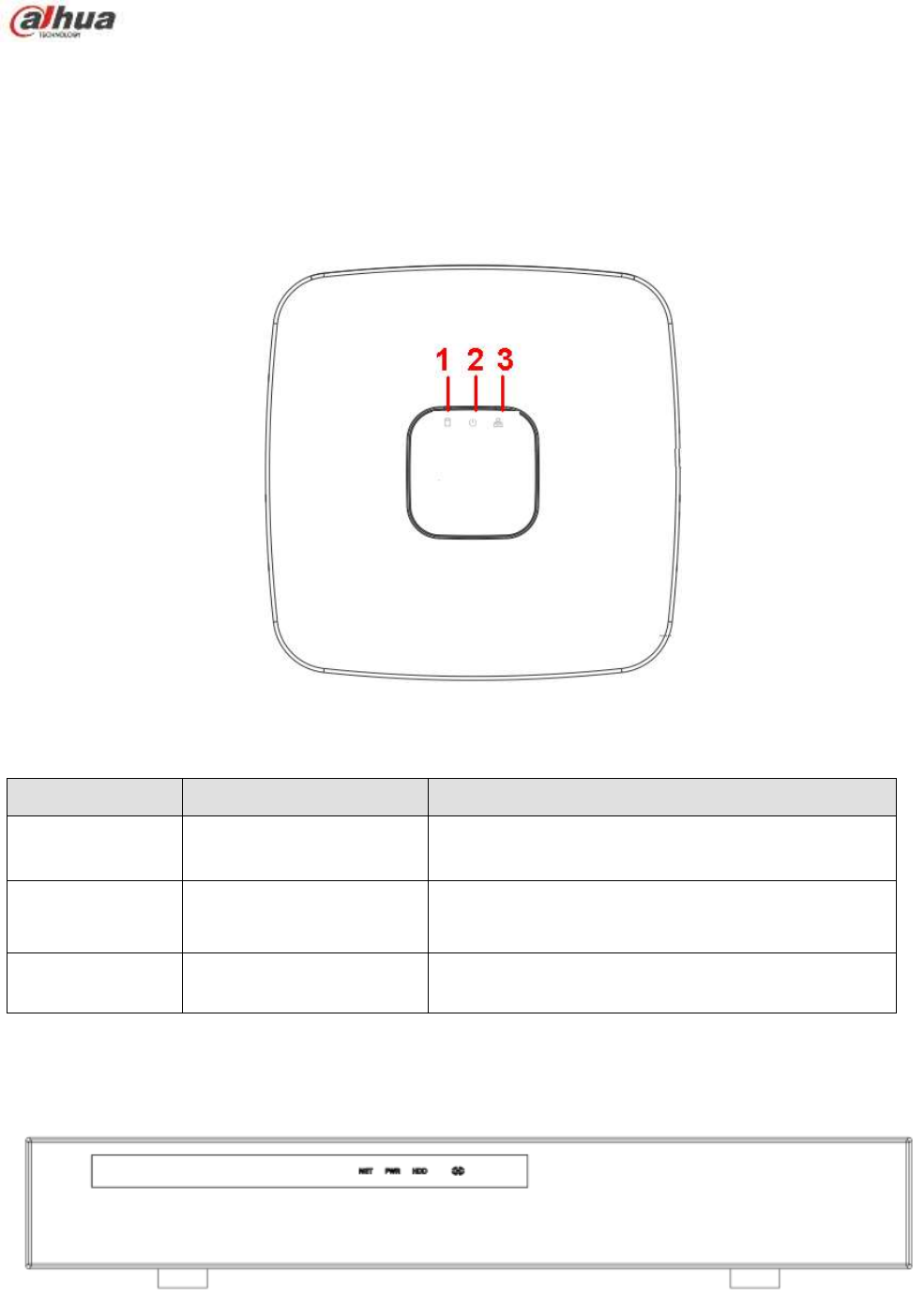
50
2 Front Panel and Rear Panel
2.1 Front Panel
2.1.1 NVR11/11-P/41/41-P/41-W/21-S2/21-P-S2/21-8P-S2 Series
The front panel is shown as in Figure 2-1.
Figure 2-1
Please refer to the following sheet for detailed information.
SN
Name
Function
1
HDD status indictor light
The red light becomes on when HDD is abnormal.
2
Power indicator light
The red light becomes on when the power
connection is OK.
3
Network status indicator
light
The red light becomes on when the network
connection is abnormal.
2.1.2 NVR11H/11H-P/41H/41H-P/41H-8P Series
The front panel is shown as in Figure 2-2.
Figure 2-2
Please refer to the following sheet for detailed information.
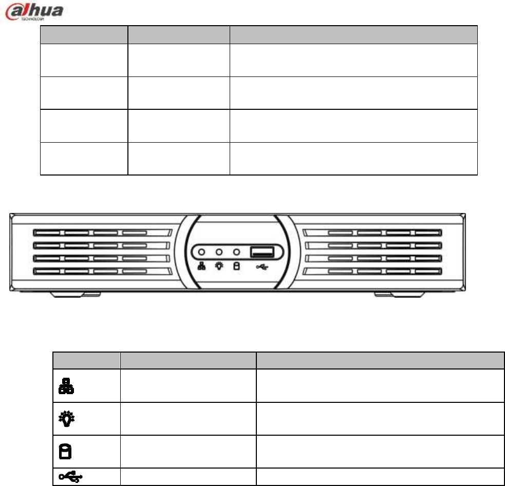
51
Icon
Name Function
NET
Network status
indicator light
The red light becomes on when the network
connection is abnormal.
PWR
Power indicator
light
The red light becomes on when the power
connection is OK.
HDD
HDD status
indictor light
The red light becomes on when HDD is abnormal.
IR
Remote control
receiver
It is to receive signal from the remote control.
2.1.3 NVR11HS Series
The front panel is shown as below. See Figure 2-3.
Figure 2-3
Please refer to the following sheet for detailed information.
Icon
Name
Function
Network status indicator
light
The red light becomes on when the network
connection is abnormal.
Power status indicator
light
The red light becomes on when the power
connection is OK.
HDD status indicator light
The red light becomes on when the HDD is
abnormal.
USB port
Connect to USB mouse,USB devices and etc.
2.1.4 NVR41HS-W-S2 Series
The front panel is shown as below. See Figure 2-4.
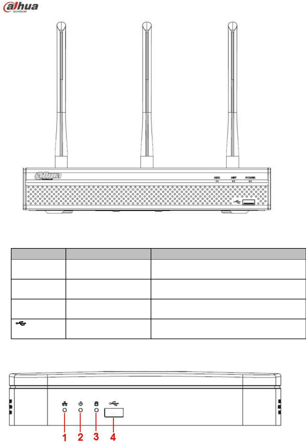
52
Figure 2-4
Please refer to the following sheet for front panel button information.
Icon
Name
Function
HDD
HDD status indicator
light
The blue light is on when the HDD is malfunction.
NET
Network status indicator
light
The blue light is on when the network connection is
abnormal.
POWER
Power status indicator light
The blue light is on when the power connection is
OK.
USB2.0 port
Connect to peripheral USB 2.0 storage device,
mouse, burner and etc.
2.1.5 NVR41-8P Series
The front panel is shown as below. See Figure 2-5.
Figure 2-5
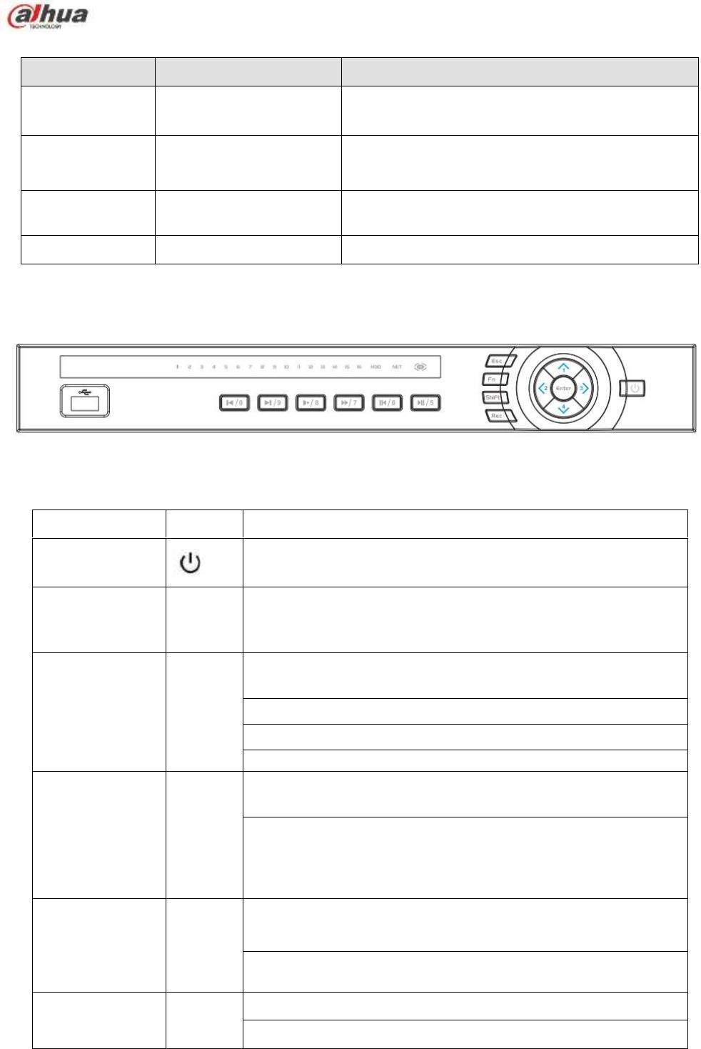
53
Please refer to the following sheet for detailed information.
SN
Name
Function
1
Network status indicator
light
The red light becomes on when the network
connection is abnormal.
2
Power indicator light
The red light becomes on when the power
connection is OK.
3
HDD status indictor light
The red light becomes on when HDD is abnormal.
4
USB
USB port
2.1.6 NVR42/42-P/42-8P/72/72-8P Series
The front panel is shown as below. See Figure 2-6.
Figure 2-6
Please refer to the following sheet for front panel button information.
Name
Icon
Function
Power button
Power button, press this button for three seconds to boot up
or shut down NVR.
Shift
Shift
In textbox, click this button to switch between numeral,
English(Small/Capitalized),donation and etc.
Up/1
Down/4
、
Activate current control, modify setup, and then move up and
down.
Increase/decrease numeral.
Assistant function such as PTZ menu.
In text mode, input number 1/4 (English character G/H/I)
Left/2
Right/3
Shift current activated control,
When playback, click these buttons to control playback bar.
In text mode, input number 2(English character A/B/C)
/3(English character D/E/F)
.
ESC
ESC
Go to previous menu, or cancel current operation.
When playback, click it to restore real-time monitor mode.
Enter
ENTER
Confirm current operation
Go to default button

54
Go to menu
Record
REC
Manually stop/start recording, working with direction keys
or numeral keys to select the recording channel.
Slow play/8
Multiple slow play speeds or normal playback.
In text mode, input number 8 (English character T/U/V).
Assistant
Fn
One-window monitor mode, click this button to display
assistant function: PTZ control and image color.
Backspace function: in numeral control or text control, press
it for 1.5seconds to delete the previous character before the
cursor.
In motion detection setup, working with Fn and direction keys
to realize setup.
In text mode, click it to switch between numeral, English
character(small/capitalized) and etc.
Realize other special functions.
Fast play/7
Various fast speeds and normal playback.
In text mode, input number 7 (English character P/Q/R/S).
Play
previous/0
|
In playback mode, playback the previous video
In text mode, input number 0.
Reverse/Pau
se/6
||
In normal playback or pause mode, click this button to
reverse
playback
In reverse playback, click this button to pause playback.
In text mode, input number 6 (English character M/N/O)
.
Play Next/9
|
In playback mode, playback the next video
In menu setup, go to down ward of the dropdown list.
In text mode, input number 9 (English character W/X/Y/Z)
.
Play/Pause /5
||
In normal playback click this button to pause playback
In pause mode, click this button to resume playback.
In text mode, input number 5(English character J/K/L).
USB port
To connect USB storage device, USB mouse.
Network
abnormal
indicator light
Net
Network error occurs or there is no network connection, the
light becomes red to alert you.
HDD
abnormal
indicator light
HDD
HDD error occurs or HDD capacity is below specified
threshold value, the light becomes red to alert you.
Record light
1-16
System is recording or not. It becomes on when system is
recording.
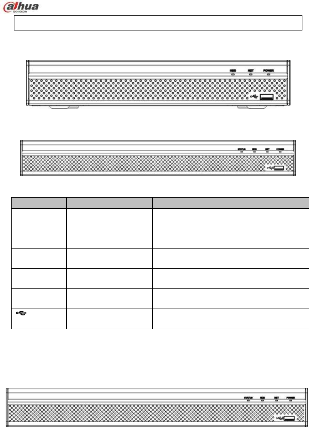
55
IR Receiver
IR
It is to receive the signal from the remote control.
2.1.7 NVR21HS-S2/21HS-P-S2/21HS-8P-S2/22-S2/22-P-S2/22-8P-S2 Series
The NVR21HS-S2/21HS-P-S2/21HS-8P-S2 series front panel is shown as below. See Figure 2-7.
Figure 2-7
The NVR22-S2/22-P-S2/22-8P-S2 series front panel is shown as in Figure 2-8.
Figure 2-8
Please refer to the following sheet for front panel button information.
Icon
Name
Function
STATUS
Status indicator light
The blue light is on when the device is malfunction.
Note
NVR21HS-S2 series product does not support
STATUS indicator light.
HDD
HDD status indicator
light
The blue light is on when the HDD is malfunction.
NET
Network status indicator
light
The blue light is on when the network connection is
abnormal.
POWER
Power status indicator light
The blue light is on when the power connection is
OK.
USB port
Connect to peripheral USB storage device, mouse
and etc.
2.1.8 NVR42-16P/42N/42-4K/42-8P-4K/44-4K/48-4K/52-4KS2/52-8P-4KS2/52-16P-4KS2
/54-4KS2/58-4KS2 Series
The NVR42-16P/42N/42-4K/42-8P-4K/52-4KS2/52-8P-4KS2/52-16P-4KS2 series front panel is shown
as in Figure 2-9.
Figure 2-9
The NVR44-4K/54-4KS2/54-16P-4KS2 series front panel is shown as in Figure 2-10.
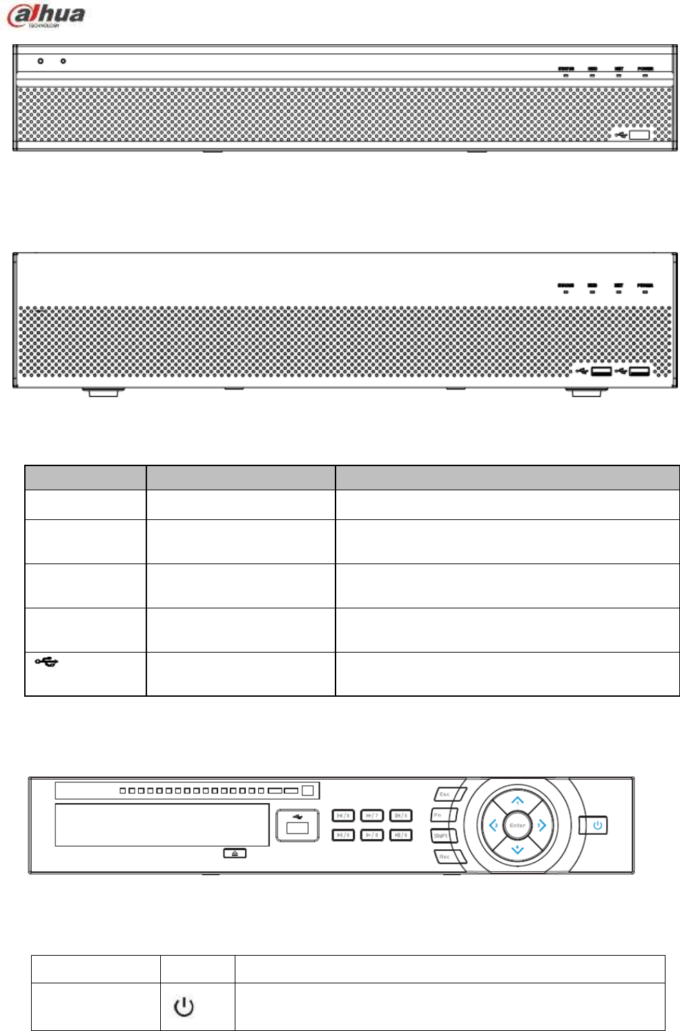
56
Figure 2-10
The NVR48-4K/58-4K/58-16P-4KS2 series front panel is shown as in Figure 2-11.
Figure 2-11
Please refer to the following sheet for front panel button information.
Icon
Name
Function
STATUS
Status indicator light
The blue light is on when the device is malfunction.
HDD
HDD status indicator
light
The blue light is on when the HDD is malfunction.
NET
Network status indicator
light
The blue light is on when the network connection is
abnormal.
POWER
Power status indicator light
The blue light is on when the power connection is
OK.
USB2.0 port
Connect to peripheral USB 2.0 storage device,
mouse, burner and etc.
2.1.9 NVR44/44-8P/44-16P/74/74-8P/74-16P Series
The front panel is shown as in Figure 2-12.
Figure 2-12
Please refer to the following sheet for front panel button information.
Name
Icon
Function
Power button
Power button, press this button for three seconds to boot up
or shut down NVR.

57
Shift
Shift
In textbox, click this button to switch between numeral,
English(Small/Capitalized),donation and etc.
Up/1
Down/4
、
Activate current control, modify setup, and then move up and
down.
Increase/decrease numeral.
Assistant function such as PTZ menu.
In text mode, input number 1/4 (English character G/H/I)
Left/2
Right/3
Shift current activated control,
When playback, click these buttons to control playback bar.
In text mode, input number 2(English character A/B/C)
/3(English character D/E/F)
.
ESC
ESC
Go to previous menu, or cancel current operation.
When playback, click it to restore real-time monitor mode.
Enter
ENTER
Confirm current operation
Go to default button
Go to menu
Record
REC
Manually stop/start recording, working with direction keys
or numeral keys to select the recording channel.
Slow play/8
Multiple slow play speeds or normal playback.
In text mode, input number 8 (English character T/U/V).
Assistant
Fn
One-window monitor mode, click this button to display
assistant function: PTZ control and image color.
Backspace function: in numeral control or text control, press
it for 1.5seconds to delete the previous character before the
cursor.
In motion detection setup, working with Fn and direction keys
to realize setup.
In text mode, click it to switch between numeral, English
character(small/capitalized) and etc.
Realize other special functions.
Fast play/7
Various fast speeds and normal playback.
In text mode, input number 7 (English character P/Q/R/S).
Play
previous/0
|
In playback mode, playback the previous video
In text mode, input number 0.
Reverse/Pau
se/6
||
In normal playback or pause mode, click this button to
reverse
playback
In reverse playback, click this button to pause playback.
In text mode, input number 6 (English character M/N/O)
.
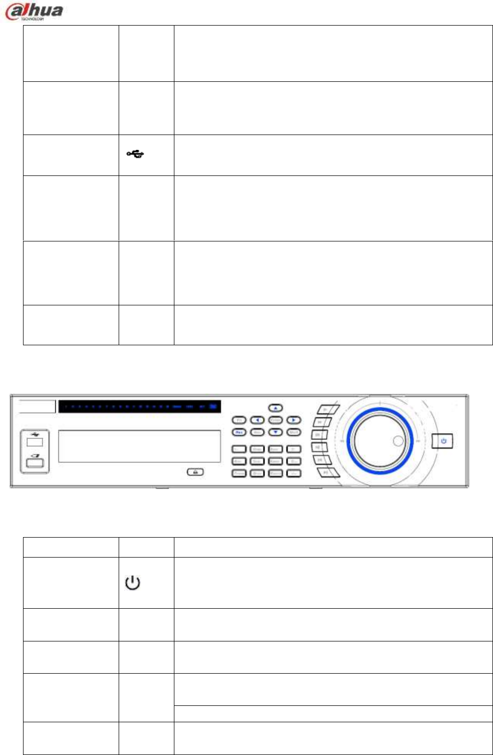
58
Play Next/9
►│
In playback mode, playback the next video
In menu setup, go to down ward of the dropdown list.
In text mode, input number 9 (English character W/X/Y/Z)
.
Play/Pause /5
►||
In normal playback click this button to pause playback
In pause mode, click this button to resume playback.
In text mode, input number 5(English character J/K/L).
USB port
To connect USB storage device, USB mouse.
Network
abnormal
indicator light
Net
Network error occurs or there is no network connection, the
light becomes red to alert you.
HDD
abnormal
indicator light
HDD
HDD error occurs or HDD capacity is below specified
threshold value, the light becomes red to alert you.
Record light
1-16
System is recording or not. It becomes on when system is
recording.
2.1.10 NVR48/48-16P/78/78-16P Series
The Front panel is shown as follows. See Figure 2-13.
Figure 2-13
Please refer to the following sheet for front panel button information.
Name
Icon
Function
Power button
Power button, press this button for three seconds to boot up or
shut down NVR.
Number button
0-9
Input Arabic number
Switch channel
Input number
more than 10
-/--
If you want to input a number more than 10, please click this
button and then input.
Shift
In textbox, click this button to switch between numeral,
English(Small/Capitalized),donation and etc.
Enable or disable tour.
Up/
Down
、
Activate current control, modify setup, and then move up and
down.

59
Increase/decrease numeral.
Assistant function such as PTZ menu.
Left/
Right
Shift current activated control, and then move left and right.
When playback, click these buttons to control playback bar.
ESC
ESC
Go to previous menu, or cancel current operation.
When playback, click it to restore real-time monitor mode.
Enter
ENTER
Confirm current operation
Go to default button
Go to menu
Record
REC
Manually stop/start recording, working with direction keys
or numeral keys to select the recording channel.
Slow play
Multiple slow play speeds or normal playback.
Assistant
Fn
One-window monitor mode, click this button to display assistant
function: PTZ control and image color.
Backspace function: in numeral control or text control, press it for
1.5seconds to delete the previous character before the cursor.
In motion detection setup, working with Fn and direction keys to
realize setup.
In text mode, click it to switch between numeral, English
character(small/capitalized) and etc.
In HDD management interface, you can click it to switch HDD
record information and other information (Menu prompt)
Realize other special functions.
Fast play
Various fast speeds and normal playback.
Play previous
|
In playback mode, playback the previous video
Reverse/Pause
In normal playback or pause mode, click this button to reverse
playback
In reverse playback, click this button to pause playback.
Play Next
|
In playback mode, playback the next video
In menu setup, go to down ward of the dropdown list.
Play/Pause
In normal playback click this button to pause playback
In pause mode, click this button to resume playback.

60
Window switch
Mult
Click it to switch one-window/multiple-window.
Shuttle(outer
ring)
In real-time monitor mode it works as left/right direction key.
Playback mode, counter clockwise to forward and clock wise to
backward.
Jog(inner dial)
Up/down direction key.
Playback mode, turn the inner dial to realized frame by frame
playback. (Only applies to some special versions.)
USB port
To connect USB storage device, USB mouse.
Remote control
indicator light
ACT
Remote control indicator light
Status indicator
light
Status
If there is Fn indicator light, current status indicator light is null.
Power indicator
light
PWR
Power indicator light
Channel indictor
light
1-32
For 4/8/16-channel series product.
The corresponding channel light becomes on when system is
recording.
For 32/64-channel series product:
When the light flashes slowly, it means the corresponding
channel of 1-16 channel is recording now (Such as channel 1).
When the light flashes fast, it means the corresponding channel
of 17-32 channel is recording now (Such as channel 17)
When the light becomes on, It means the corresponding 2
channels are recoding now (Such as channel 1 and channel 17.).
The channel indictor light here does not show the status of
the 33-64-channel.
IR Receiver
IR
It is to receive the signal from the remote control.
2.1.11 NVR78-RH Series
The front panel is shown as below. See Figure 2-14.
Figure 2-14
Please refer to the following sheet for front panel button information.

61
Name
Icon
Function
Power button
Power button, press this button for three seconds to boot up or
shut down NVR.
Number button
0-9
Input Arabic number
Switch channel
Input number
more than 10
-/--
If you want to input a number more than 10, please click this
button and then input.
Shift
In textbox, click this button to switch between numeral,
English(Small/Capitalized),donation and etc.
Enable or disable tour.
Up/
Down
、
Activate current control, modify setup, and then move up and
down.
Increase/decrease numeral.
Assistant function such as PTZ menu.
Left/
Right
Shift current activated control, and then move left and right.
When playback, click these buttons to control playback bar.
ESC
ESC
Go to previous menu, or cancel current operation.
When playback, click it to restore real-time monitor mode.
Enter
ENTER
Confirm current operation
Go to default button
Go to menu
Record
REC
Manually stop/start recording, working with direction keys
or numeral keys to select the recording channel.
Slow play
Multiple slow play speeds or normal playback.
Assistant
Fn
One-window monitor mode, click this button to display assistant
function: PTZ control and image color.
Backspace function: in numeral control or text control, press it for
1.5 seconds to delete the previous character before the cursor.
In motion detection setup, working with Fn and direction keys to
realize setup.
In text mode, click it to switch between numeral, English
character(small/capitalized) and etc.
In HDD management interface, you can click it to switch HDD
record information and other information (Menu prompt)
Realize other special functions.

62
Fast play
Various fast speeds and normal playback.
Play previous
|
In playback mode, playback the previous video
Reverse/Pause
||
In normal playback or pause mode, click this button to reverse
playback
In reverse playback, click this button to pause playback.
Play Next
|
In playback mode, playback the next video
In menu setup, go to down ward of the dropdown list.
Play/Pause
||
In normal playback click this button to pause playback
In pause mode, click this button to resume playback.
Window switch
Mult
Click it to switch one-window/multiple-window.
Shuttle(outer
ring)
In real-time monitor mode it works as left/right direction key.
Playback mode, counter clockwise to forward and clock wise to
backward.
Jog(inner dial)
Up/down direction key.
Playback mode, turn the inner dial to realized frame by frame
playback. (Only applies to some special versions.)
USB port
To connect USB storage device, USB mouse.
Remote control
receiver
IR
It is to receive signal from the remote control.
Remote control
indicator light
ACT
Remote control indicator light
Status indicator
light
Status
The light is on if device operates properly.
Power indicator
light
POWER
Power indicator light
Record light
1-16
It becomes on when system is recording.
HDD abnormal
status indictor
light
HDD
It becomes on when there is no HDD, HDD error occurs, or HDD
is full.
2.1.12 NVR70/70-R Series
The front panel is shown as in Figure 2-15.
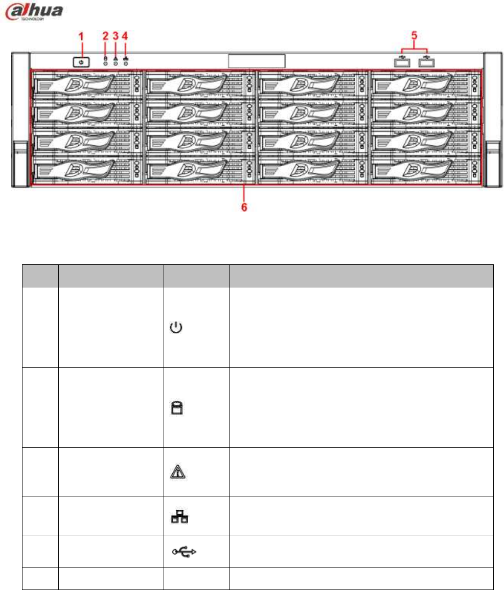
63
Figure 2-15
Please refer to the following sheet for front panel button information.
SN
Name
Icon Function
1
Power button
Press it once to turn on the device.
Press it for a long time to turn off the device (Usually
we do not recommend).
Press power button for a long time or pull out the
power cable may result in device auto restart.
2
System HDD
Indicator light
The blue light flashes when system is reading or
writing the system HDD.
In the system HDD, there are device important
configuration file, factory default configuration file,
device initial boot up data.
3
Alarm indicator light
The alarm indicator light becomes on once an alarm
occurred. It becomes on via the software detection.
The alarm includes local alarm, no disk and etc.
4
Network indicator
light
The network indicator light is blue and it flashes when
you connect the device to the network.
5
USB2.0 port
Connect to USB2.0 storage device, mouse, USB
burner and etc.
6
16 HDD slot
-
/
After you remove the front panel, you can see there are 16 HDDs. From the left to the right and from the
top to the bottom, it ranges from 1~4, 5~8, 6~12, 13~16. See Figure 2-16.
You can see there are two indicator light s on the HDD bracket.
The power indicator light is at the top. The light is yellow after you connected the device to the power.
The read-write indicator light is at the bottom. The blue light flashes when system is reading or
writing the data.
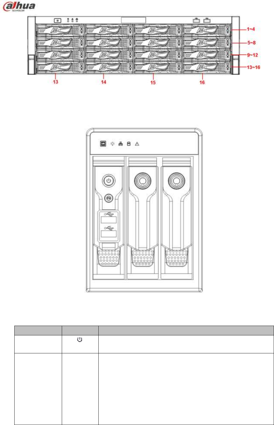
64
Figure 2-16
2.1.13 NVR42V-8P Series
The front panel is shown as below. See Figure 2-17
Figure 2-17
Please refer to the following sheet for front panel button information.
Name
Icon
Function
Power button
Power button, press this button for three seconds to boot up or
shut down NVR.
Assistant
Fn
One-window monitor mode, click this button to display
assistant function: PTZ control and image color.
Backspace function: in numeral control or text control,
press it for 1.5 seconds to delete the previous character
before the cursor.
In motion detection setup, working with Fn and direction
keys to realize setup.
In text mode, click it to switch between numeral, English
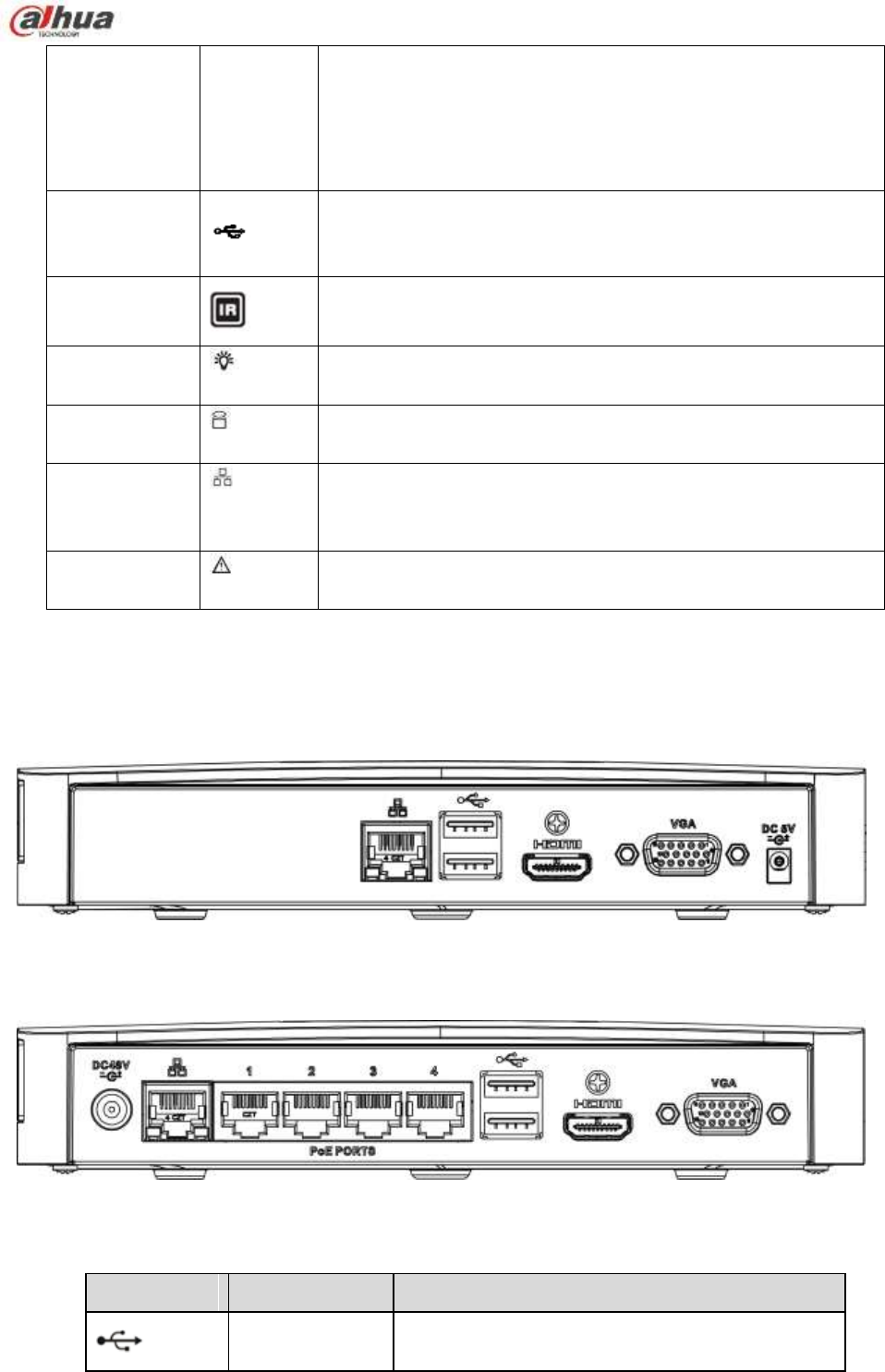
65
character (small/capitalized) and etc.
In HDD management interface, you can click it to switch
HDD record information and other information (Menu
prompt)
Realize other special functions.
USB2.0 port
To connect USB2.0 storage device, USB2.0 mouse, burner and
etc.
IR receive
window
It is to receive the IR signal from the remote control.
Power indicator
light
Power indicator light.
HDD abnormal
indicator light
HDD error occurs or HDD capacity is below specified threshold
value, the light becomes red to alert you.
Network
abnormal
indicator light
Network error occurs or there is no network connection, the light
becomes red to alert you.
Alarm indicator
light
The light becomes on when an alarm occurred.
2.2 Rear Panel
2.2.1 NVR100/100-P Series
The NVR100 rear panel is shown as below. See Figure 2-18.
Figure 2-18
The NVR100-P rear panel is shown as below. See Figure 2-19.
Figure 2-19
Please refer to the following sheet for detailed information.
Port Name
Connection
Function
USB2.0 port
USB2.0 port. Connect to mouse, USB storage
device, USB burner and etc.
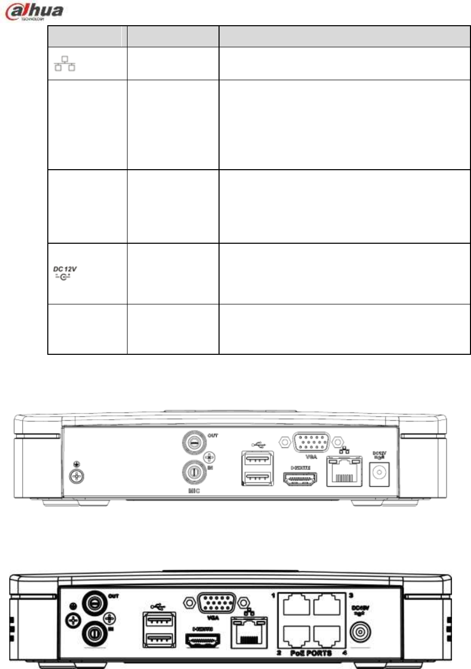
66
Port Name
Connection Function
Network port
10M/100Mbps self-adaptive Ethernet port.
Connect to the network cable.
HDMI
High Definition
Media Interface
High definition audio and video signal output port.
It transmits uncompressed high definition video
and multiple-channel data to the HDMI port of the
display device. HDMI version is 1.4.
VGA
VGA video
output port
VGA video output port. Output analog video
signal. It can connect to the monitor to view analog
video.
Power input port
Power socket.
For NVR100 series, input DC 5V/2A.
For NVR100-P series, input DC 48V/1.25A.
PoE PORT
PoE port Built-in switch. Support PoE function.
For PoE series product, you can use this port to
provide power to the network camera.
2.2.2 NVR11/11-P Series
The NVR11 rear panel is shown as below. See Figure 2-20.
Figure 2-20
The NVR11-P rear panel is shown as below. See Figure 2-21.
Figure 2-21
Please refer to the following sheet for detailed information.
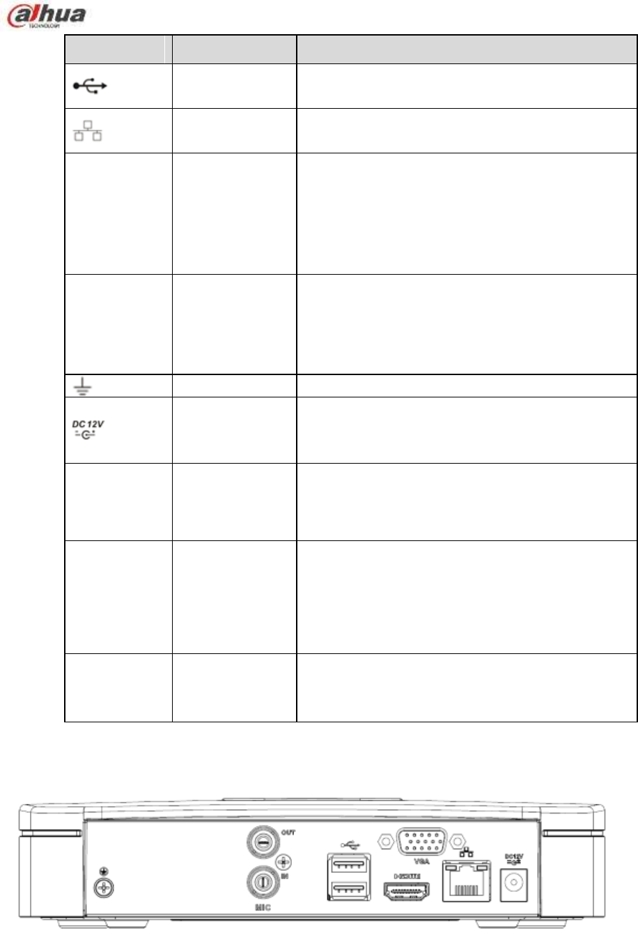
67
Port Name
Connection Function
USB2.0 port
USB2.0 port. Connect to mouse, USB storage
device, USB burner and etc.
Network port
10M/100Mbps self-adaptive Ethernet port.
Connect to the network cable.
HDMI
High Definition
Media Interface
High definition audio and video signal output port.
It transmits uncompressed high definition video
and multiple-channel data to the HDMI port of the
display device. HDMI version is 1.4.
VGA
VGA video
output port
VGA video output port. Output analog video
signal. It can connect to the monitor to view analog
video.
GND Ground end
Power input port
Power socket.
For NVR11 series, input DC 12V/2A.
For NVR11-P series, input DC 48V/1.25A.
MIC IN
Audio input port Bidirectional talk input port. It is to receive the
analog audio signal output from the devices such
as microphone, pickup.
MIC OUT
Audio output
port
Audio output port. It is to output the analog audio
signal to the devices such as the sound box.
Bidirectional talk output.
Audio output on 1-window video monitor.
Audio output on 1-window video playback.
PoE PORT
PoE port
Built-in switch. Support PoE function.
For PoE series product, you can use this port to
provide power to the network camera.
2.2.3 NVR41/41-P/41-8P/41-W Series
The NVR41 rear panel is shown as below. See Figure 2-22.
Figure 2-22
The NVR41-P rear panel is shown as below. See Figure 2-23.
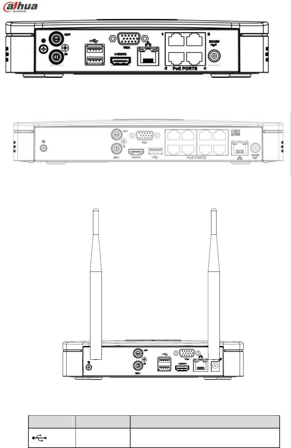
68
Figure 2-23
The NVR41-8P rear panel is shown as below. See Figure 2-24.
Figure 2-24
The NVR41-W rear panel is shown as below. See Figure 2-25.
Figure 2-25
Please refer to the following sheet for detailed information.
Port Name
Connection
Function
USB2.0 port
USB2.0 port. Connect to mouse, USB storage
device, USB burner and etc.
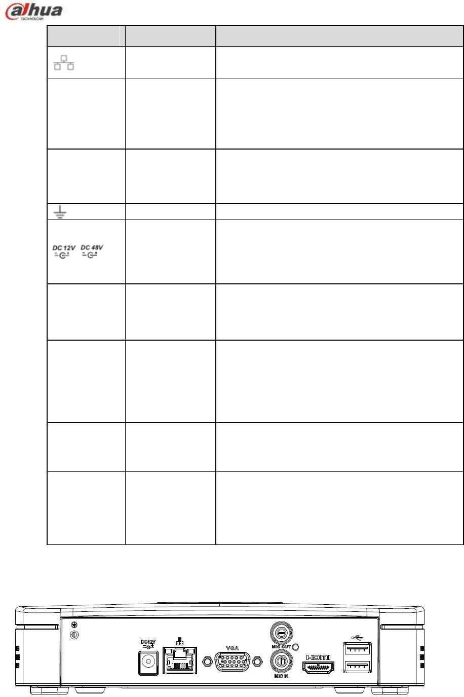
69
Port Name
Connection Function
Network port
10M/100Mbps self-adaptive Ethernet port.
Connect to the network cable.
HDMI
High Definition
Media Interface
High definition audio and video signal output port.
It transmits uncompressed high definition video
and multiple-channel data to the HDMI port of the
display device. HDMI version is 1.4.
VGA
VGA video
output port
VGA video output port. Output analog video
signal. It can connect to the monitor to view analog
video.
GND
Ground end
/
Power input port
Power socket.
For NVR41 series, input DC 12V/2A.
For NVR41-P series, input DC 48V/1.5A.
For NVR41-8P series, input DC 48V/2A.
MIC IN
Audio input port Bidirectional talk input port. It is to receive the
analog audio signal output from the devices such
as microphone, pickup.
MIC OUT
Audio output
port
Audio output port. It is to output the analog audio
signal to the devices such as the sound box.
Bidirectional talk output.
Audio output on 1-window video monitor.
Audio output on 1-window video playback.
PoE PORT
PoE port
Built-in switch. Support PoE function.
For PoE series product, you can use this port to
provide power to the network camera.
Wireless AP
Support wireless hotspot function. Use WIFI to
connect to the network camera when there is a
hotspot.
For 41-W series only.
2.2.4 NVR21-S2/21-P-S2/21-8P-S2 Series
The NVR21-S2 is shown as in Figure 2-26.
Figure 2-26
The NVR21-P-S2 is shown as in Figure 2-27.
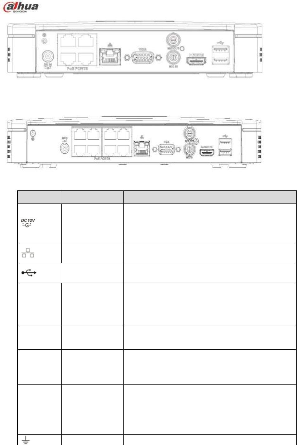
70
Figure 2-27
The NVR21-8P-S2 is shown as in Figure 2-28.
Figure 2-28
Please refer to the following sheet for detailed information.
Port Name
Connection
Function
Power input port
Power socket
For NVR21-S2,input DC 12V/2A.
For NVR21-P-S2,input DC 48V/1.25A.
For NVR21-8P-S2,input DC 48V/2A.
Network port
10M/100Mbps self-adaptive Ethernet port. Connect to the
network cable.
USB port
USB port. Connect to mouse, USB storage device and
etc.
HDMI
High Definition
Media Interface
High definition audio and video signal output port. It
transmits uncompressed high definition video and
multiple-channel data to the HDMI port of the display
device. HDMI version is 1.4.
VGA
VGA video output
port
VGA video output port. Output analog video signal. It can
connect to the monitor to view analog video.
MIC IN
Audio input port
Bidirectional talk input port. It is to receive the analog
audio signal output from the devices such as microphone,
pickup.
MIC OUT
Audio output port
Audio output port. It is to output the analog audio signal to
the devices such as the sound box.
Bidirectional talk output.
Audio output on 1-window video monitor.
Audio output on 1-window video playback.
GND
Ground end
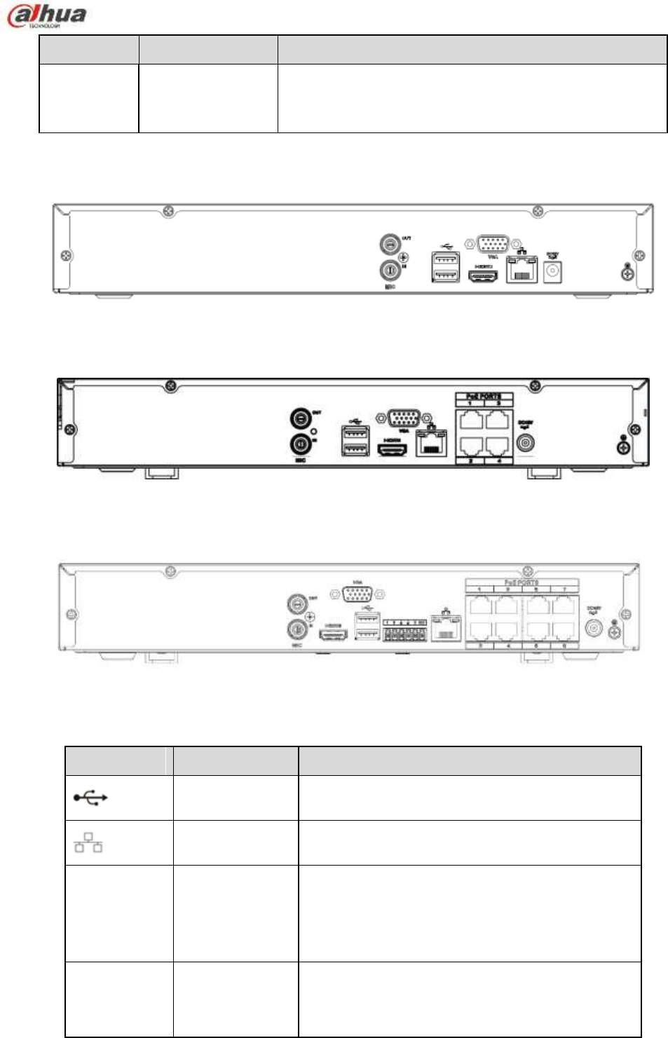
71
Port Name
Connection
Function
PoE
PORTS
PoE port
Built-in switch. Support PoE function.
For PoE series product, you can use this port to provide
power to the network camera.
2.2.5 NVR11H/11H-P/41H/41H-P/41H-8P Series
The NVR11H/41H rear panel is shown as in Figure 2-29.
Figure 2-29
The NVR11H-P/41H-P rear panel is shown as in Figure 2-30.
Figure 2-30
The NVR41H-8P rear panel is shown as in Figure 2-31.
Figure 2-31
Please refer to the following sheet for detailed information.
Port Name
Connection
Function
USB2.0 port
USB2.0 port. Connect to mouse, USB storage
device, USB burner and etc.
Network port
10M/100Mbps self-adaptive Ethernet port.
Connect to the network cable.
HDMI
High Definition
Media Interface
High definition audio and video signal output port.
It transmits uncompressed high definition video
and multiple-channel data to the HDMI port of the
display device. HDMI version is 1.4.
VGA
VGA video
output port
VGA video output port. Output analog video
signal. It can connect to the monitor to view analog
video.
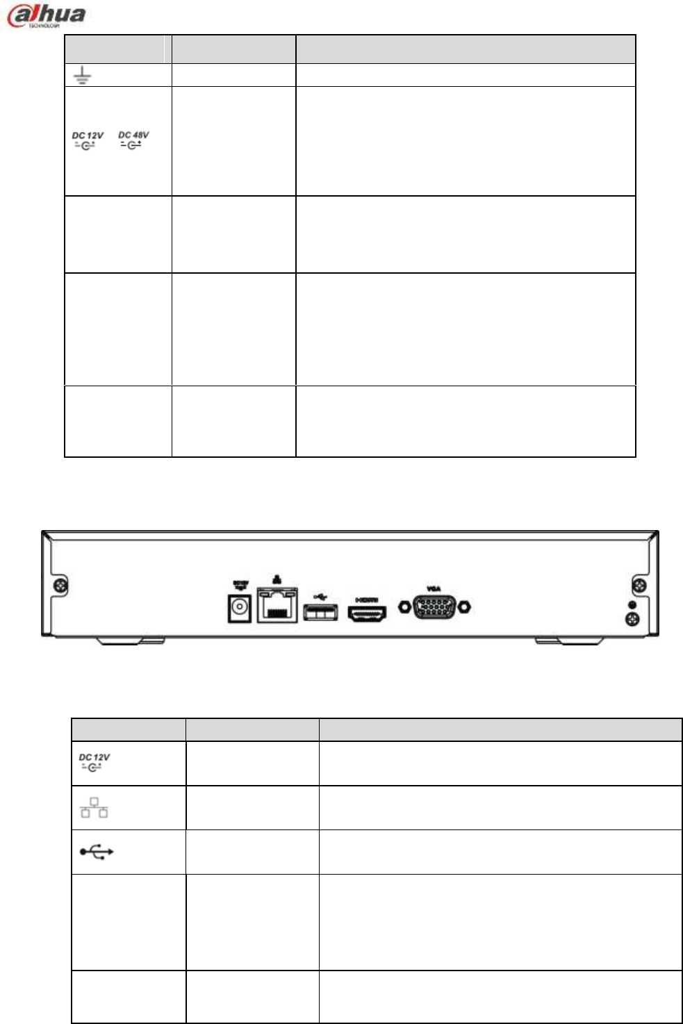
72
Port Name
Connection Function
GND
Ground end
/
Power input port
Power socket.
For NVR41 series, input DC 12V/2A.
For NVR41H-P series, input DC 48V/1.5A.
For NVR11H-P series, input DC 48V/1.25A.
For NVR41H-8P series, input DC 48V/2A.
MIC IN
Audio input port
Bidirectional talk input port. It is to receive the
analog audio signal output from the devices such
as microphone, pickup.
MIC OUT
Audio output
port
Audio output port. It is to output the analog audio
signal to the devices such as the sound box.
Bidirectional talk output.
Audio output on 1-window video monitor.
Audio output on 1-window video playback.
PoE PORT
PoE port Built-in switch. Support PoE function.
For PoE series product, you can use this port to
provide power to the network camera.
2.2.6 NVR11HS Series
The series rear panel is shown as below. See Figure 2-32.
Figure 2-32
Please refer to the following sheet for detailed information.
Icon
Name
Function
Power input
socket.
Power socket. Input DC12V/1.5A.
Network port
10M/100Mbps self-adaptive Ethernet port. Connect to
the network cable.
USB2.0 port
USB2.0 port. Connect to mouse, USB storage device,
and etc.
HDMI
High Definition
Media Interface
High definition audio and video signal output port. It
transmits uncompressed high definition video and
multiple-channel data to the HDMI port of the display
device. HDMI version is 1.4.
VGA
VGA video output
port
VGA video output port. Output analog video signal. It
can connect to the monitor to view analog video.
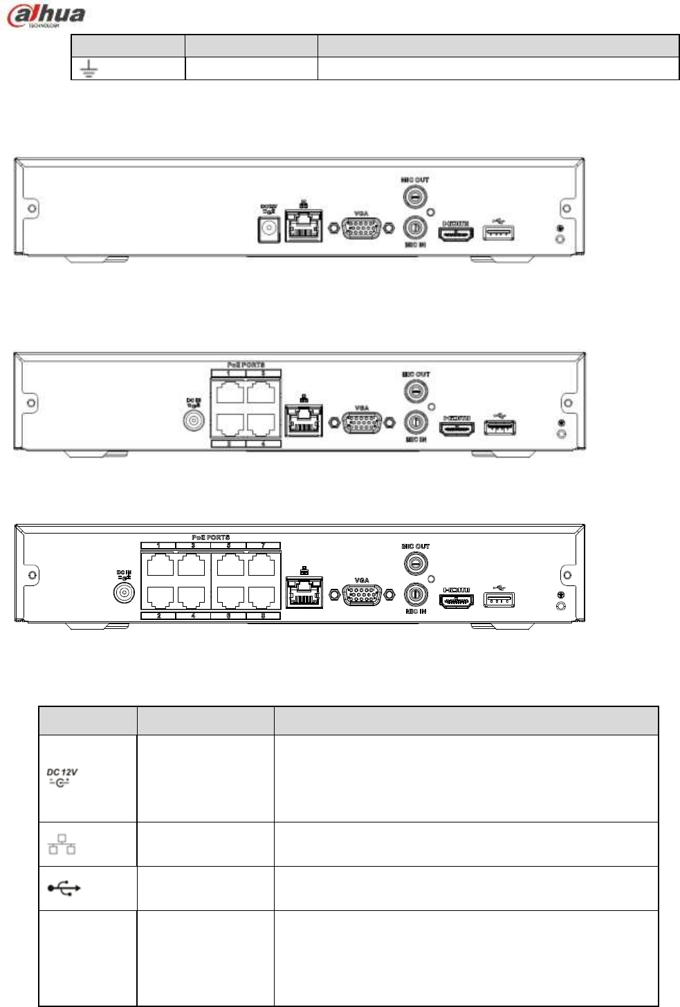
73
Icon
Name Function
GND
Ground end
2.2.7 NVR21HS-S2/21HS-P-S2/21HS-8P-S2 Series
The NVR21HS-S2 series rear panel is shown as below. See Figure 2-33.
Figure 2-33
The NVR21HS-P-S2 series rear panel is shown as below. See Figure 2-34.
Figure 2-34
The NVR21HS-8P-S2 series rear panel is shown as below. See Figure 2-35.
Figure 2-35
Please refer to the following sheet for detailed information.
Port Name
Connection
Function
Power input port
Power socket.
For NVR21HS-S2, input DC 12V/2A.
For NVR21HS-P-S2, input DC 48V/1.25A.
For NVR21HS-8P-S2, input DC 48V/2A.
Network port
10M/100Mbps self-adaptive Ethernet port. Connect to the
network cable.
USB port
USB port. Connect to mouse, USB storage device and
etc.
HDMI
High Definition
Media Interface
High definition audio and video signal output port. It
transmits uncompressed high definition video and
multiple-channel data to the HDMI port of the display
device. HDMI version is 1.4.
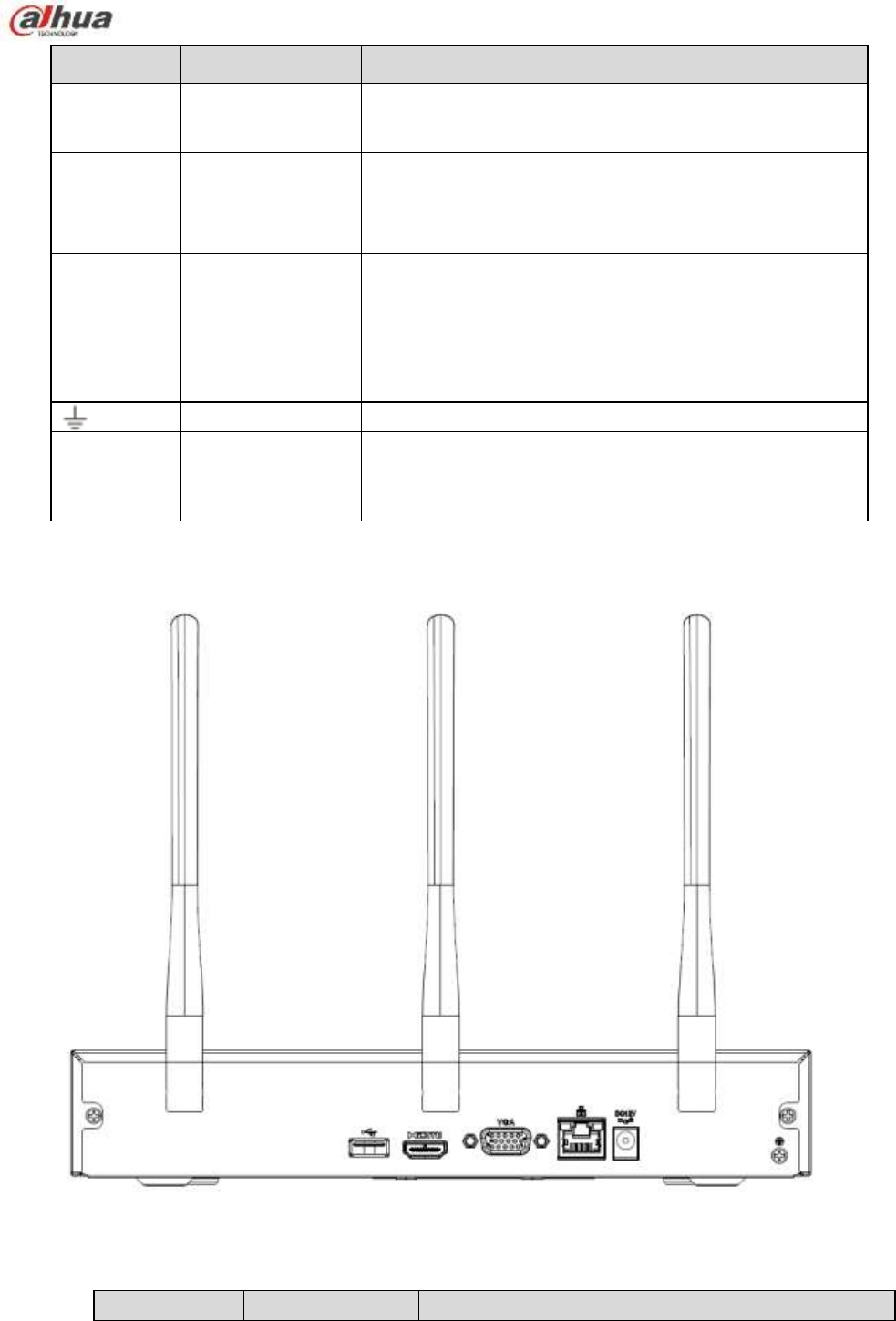
74
Port Name
Connection
Function
VGA
VGA video output
port
VGA video output port. Output analog video signal. It can
connect to the monitor to view analog video.
MIC IN
Audio input port
Bidirectional talk input port. It is to receive the analog
audio signal output from the devices such as microphone,
pickup.
MIC OUT
Audio output port
Audio output port. It is to output the analog audio signal to
the devices such as the sound box.
Bidirectional talk output.
Audio output on 1-window video monitor.
Audio output on 1-window video playback.
GND
Ground end
PoE
PORTS
PoE port
Built-in switch. Support PoE function.
For PoE series product, you can use this port to provide
power to the network camera.
2.2.8 NVR41HS-W-S2 Series
The NVR41HS-W-S2 rear panel is shown as below. See Figure 2-36.
Figure 2-36
Please refer to the following sheet for detailed information.
Icon
Name
Function
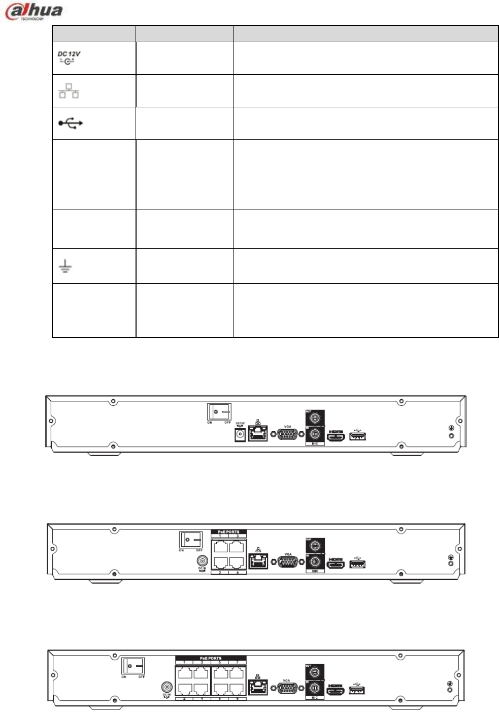
75
Icon
Name Function
Power input
socket.
Power socket. Input DC12V/2A.
Network port
10M/100Mbps self-adaptive Ethernet port. Connect to
the network cable.
USB2.0 port
USB2.0 port. Connect to mouse, USB storage device,
and etc.
HDMI
High Definition
Media Interface
High definition audio and video signal output port. It
transmits uncompressed high definition video and
multiple-channel data to the HDMI port of the display
device. HDMI version is 1.4.
VGA
VGA video output
port
VGA video output port. Output analog video signal. It
can connect to the monitor to view analog video.
GND Ground end
Wireless AP
Support wireless hotspot function. Use WIFI to
connect to the network camera when there is a
hotspot.
2.2.9 NVR22-S2/22-P-S2/22-8P-S2 Series
The NVR22-S2 series rear panel is shown as below. See Figure 2-37.
Figure 2-37
The NVR22-P-S2 series rear panel is shown as below. See Figure 2-38.
Figure 2-38
The NVR22-8P-S2 series rear panel is shown as below. See Figure 2-39.
Figure 2-39
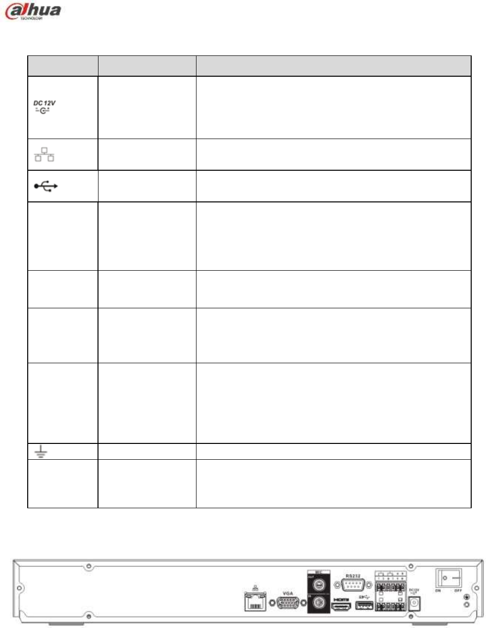
76
Please refer to the following sheet for detailed information.
Port Name
Connection
Function
Power input port
Power socket.
For NVR22-S2, input DC 12V/4A.
For NVR22-P-S2, input DC 48V/1.5A.
For NVR22-8P-S2, input DC 53V 120W.
Network port
10M/100Mbps self-adaptive Ethernet port. Connect to the
network cable.
USB port
USB port. Connect to mouse, USB storage device and
etc.
HDMI
High Definition
Media Interface
High definition audio and video signal output port. It
transmits uncompressed high definition video and
multiple-channel data to the HDMI port of the display
device. HDMI version is 1.4.
VGA
VGA video output
port
VGA video output port. Output analog video signal. It can
connect to the monitor to view analog video.
MIC IN
Audio input port
Bidirectional talk input port. It is to receive the analog
audio signal output from the devices such as microphone,
pickup.
MIC OUT
Audio output port
Audio output port. It is to output the analog audio signal to
the devices such as the sound box.
Bidirectional talk output.
Audio output on 1-window video monitor.
Audio output on 1-window video playback.
GND
Ground end
PoE
PORTS
PoE port
Built-in switch. Support PoE function.
For PoE series product, you can use this port to provide
power to the network camera.
2.2.10 NVR42/42N/42-P/42-8P/42-16P Series
The NVR42 series rear panel is shown as below. See Figure 2-40.
Figure 2-40
The NVR42N series rear panel is shown as below. See Figure 2-41.
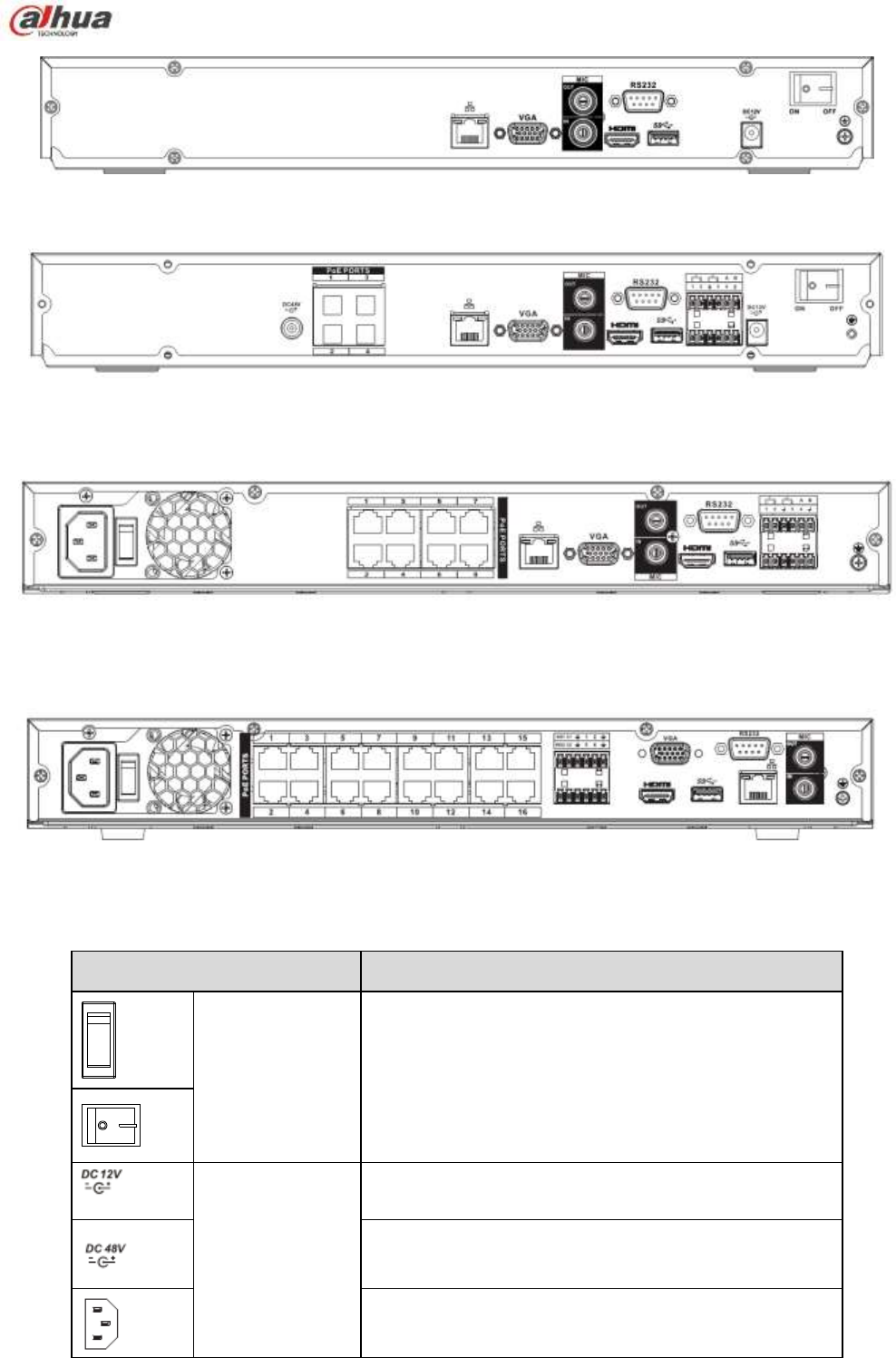
77
Figure 2-41
The NVR42-P series rear panel is shown as below. See Figure 2-42.
Figure 2-42
The NVR42-8P series rear panel is shown as below. See Figure 2-43.
Figure 2-43
The NVR42-16P series rear panel is shown as below. See Figure 2-44.
Figure 2-44
Please refer to the following sheet for detailed information.
Name
Function
Power switch
Power on/off button.
Power input port
Input DC 12V/5A.
For NVR42 series product only.
Switch power port. Input DC 48//1.04A.
For NVR42-P series product only.
Input AC 100~240V.
For NVR42-8P/42-16P series product only.

78
Name
Function
MIC IN
Audio input port
Bidirectional talk input port. It is to receive the analog
audio signal output from the devices such as
microphone, pickup.
MIC OUT
Audio output port
Audio output port. It is to output the analog audio signal
to the devices such as the sound box.
Bidirectional talk output.
Audio output on 1-window video monitor.
Audio output on 1-window video playback.
1~4
Alarm input port
1~4
There are two types; NO (normal open)/NC
(normal close).
When your alarm input device is using external
power, please make sure the device and the NVR
have the same ground.
GND
Alarm input ground port.
N1, N2
Alarm output port
1~2
2 groups of alarm output ports. (Group 1:port
NO1~C1,Group 2:port NO2~C2).Output alarm
signal to the alarm device. Please make sure there
is power to the external alarm device.
NO:Normal open alarm output port.
C:Alarm output public end.
C1, C2
A
RS-485
communication
port
RS485_A port. It is the cable A. You can connect to the
control devices such as speed dome PTZ.
B
RS485_B.It is the cable B. You can connect to the
control devices such as speed dome PTZ.
Network port
10M/100M/1000Mbps self-adaptive Ethernet port.
Connect to the network cable.
USB2.0
port
USB2.0 port. Connect to mouse, USB storage device,
USB burner and etc.
RS-232
RS-232 debug
COM.
It is for general COM debug to configure IP address or
transfer transparent COM data.
HDMI
High Definition
Media Interface
High definition audio and video signal output port. It
transmits uncompressed high definition video and
multiple-channel data to the HDMI port of the display
device. HDMI version is 1.4.
VGA
VGA video
output port
VGA video output port. Output analog video signal. It
can connect to the monitor to view analog video.
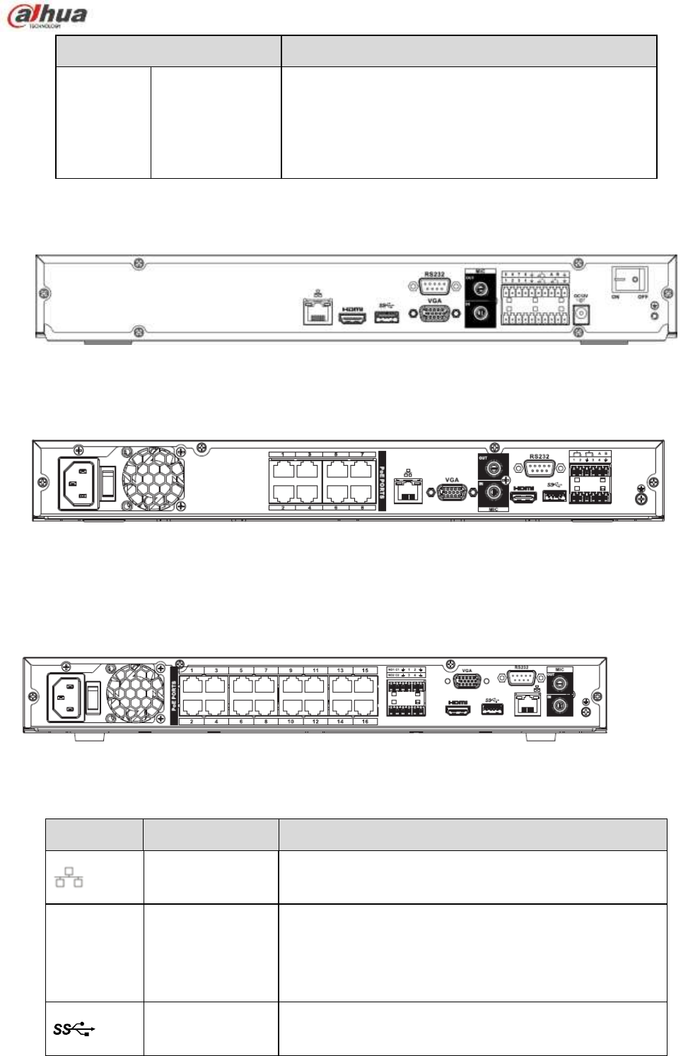
79
Name
Function
PoE
PORTS
/
Bult-in Switch. Support PoE.
The 4 PoE series product supports total 48V 50W.
The 8 PoE series product supports total 48V 120W.
The 16 PoE series product supports total 120W. One
PoE port max supports 15W.
2.2.11 NVR42-4K/52-4KS2/52-8P-4KS2/52-16P-4KS2 Series
The NVR42-4K/52-4KS2 series rear panel is shown as below. See Figure 2-45.
Figure 2-45
The NVR52-8P-4KS2 series rear panel is shown as below. See Figure 2-46.
Figure 2-46
The NVR52-16P-4KS2 series rear panel is shown as below. See Figure 2-47.
Figure 2-47
Please refer to the following sheet for detailed information.
Icon
Port Name
Function
Network port
10M/100M/1000Mbps self-adaptive Ethernet port.
Connect to the network cable.
HDMI
High Definition
Media Interface
High definition audio and video signal output port. It
transmits uncompressed high definition video and
multiple-channel data to the HDMI port of the display
device. HDMI version is 1.4.
USB3.0 port
USB3.0 port. Connect to mouse, USB storage device,
USB burner and etc.

80
Icon
Port Name
Function
RS-232
RS-232 debug
COM.
It is for general COM debug to configure IP address or
transfer transparent COM data.
VGA
VGA video output
port
VGA video output port. Output analog video signal. It can
connect to the monitor to view analog video.
MIC IN
Audio input port
Bidirectional talk input port. It is to receive the analog
audio signal output from the devices such as
microphone, pickup.
MIC OUT
Audio output port
Audio output port. It is to output the analog audio signal
to the devices such as the sound box.
Bidirectional talk output.
Audio output on 1-window video monitor.
Audio output on 1-window video playback.
1~8
Alarm input port
1~8
There are two groups. The first group is from port 1
to port 4; the second group is from port 5 to port 8.
They are to receive the signal from the external
alarm source. There are two types; NO (normal
open)/NC (normal close).
When your alarm input device is using external
power, please make sure the device and the NVR
have the same ground.
GND
Alarm input ground port.
NO1~NO3
Alarm output port
1~3
3 groups of alarm output ports. (Group 1:port
NO1 ~C1,Group 2:port NO2 ~C2,Group 3:port
NO3~C3)).Output alarm signal to the alarm device.
Please make sure there is power to the external
alarm device.
NO:Normal open alarm output port.
C:Alarm output public end.
C1~C3
A
RS-485
communication
port
RS485_A port. It is the cable A. You can connect to the
control devices such as speed dome PTZ.
B
RS485_B.It is the cable B. You can connect to the
control devices such as speed dome PTZ.
Power input port
Input DC 12V/4A.
Power
switch
/
Power on/off button.
PoE
PORTS
/
Bult-in Switch. Support PoE..
The 8 PoE series product supports total 130W.
The 16 PoE series product supports total 130W.
2.2.12 NVR42-8P-4K Series
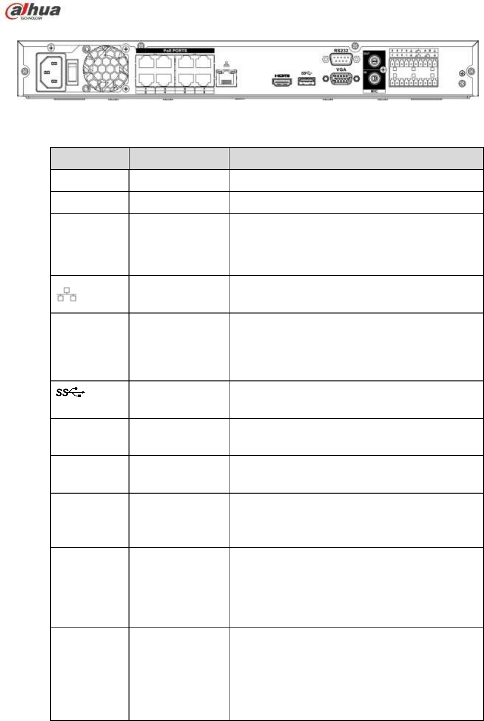
81
The NVR42-8P-4K series rear panel is shown as below. See Figure 2-48.
Figure 2-48
Please refer to the following sheet for detailed information.
Icon
Port Name
Function
Power socket
/
Input AC 220V.
Power switch
/
Power on/off button.
PoE PORTS
PoE port
Built-in Switch,support PoE. The PoE PORTS can
provide power to the network camera.
The 8 PoE ports series product can support 48V
120W.
Network port 10M/100M/1000Mbps self-adaptive Ethernet port.
Connect to the network cable.
HDMI
High Definition
Media Interface
High definition audio and video signal output port. It
transmits uncompressed high definition video and
multiple-channel data to the HDMI port of the display
device. HDMI version is 1.4.
USB3.0 port
USB3.0 port. Connect to mouse, USB storage
device, USB burner and etc.
RS-232
RS-232 debug
COM.
It is for general COM debug to configure IP address
or transfer transparent COM data.
VGA
VGA video output
port
VGA video output port. Output analog video signal. It
can connect to the monitor to view analog video.
MIC IN
Audio input port
Bidirectional talk input port. It is to receive the analog
audio signal output from the devices such as
microphone, pickup.
MIC OUT
Audio output port
Audio output port. It is to output the analog audio
signal to the devices such as the sound box.
Bidirectional talk output.
Audio output on 1-window video monitor.
Audio output on 1-window video playback.
1~4
Alarm input port
1~4
They are to receive the signal from the external
alarm source. There are two types; NO (normal
open)/NC (normal close).
When your alarm input device is using external
power, please make sure the device and the
NVR have the same ground.
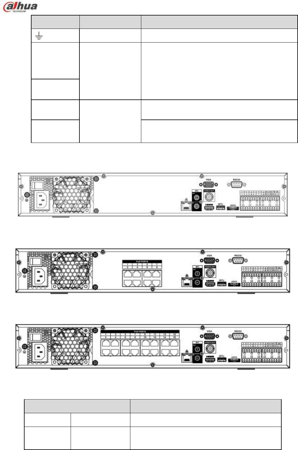
82
Icon
Port Name Function
GND
Alarm input ground port.
N1,N2
Alarm output port
1~2
2 groups of alarm output ports.(group 1:port
NO1~C1, group 2:port NO2~C2). Output
alarm signal to the alarm device. Please make
sure there is power to the external alarm device.
NO:Normal open alarm output port.
C:Alarm output public end.
C1~C2
A
RS-485
communication
port
RS485_A port. It is the cable A. You can connect to
the control devices such as speed dome PTZ.
B
RS485_B.It is the cable B. You can connect to the
control devices such as speed dome PTZ.
2.2.13 NVR44/44-8P/44-16P Series
The NVR44 series rear panel is shown as below. See Figure 2-49.
Figure 2-49
The NVR44-8P series rear panel is shown as below. See Figure 2-50.
Figure 2-50
The NVR44-16P series rear panel is shown as below. See Figure 2-51.
Figure 2-51
Please refer to the following sheet for detailed information.
Name
Function
Power switch
/
Power on-off button
Power input
port
/
Input AC 100~240V.

83
Name
Function
MIC IN
Audio input port
Bidirectional talk input port. It is to receive the
analog audio signal output from the devices such
as microphone, pickup.
MIC OUT
Audio output port
Audio output port. It is to output the analog audio
signal to the devices such as the sound box.
Bidirectional talk output.
Audio output on 1-window video monitor.
Audio output on 1-window video playback.
VIEDEO OUT
Video output port
CVBS output
1~16
Alarm input port
1~16
There are four groups. The first group is from
port 1 to port 4, the second group is from port 5
to port 8, the third group is from 9 to 12, and
the fourth group is from 13 to 16. They are to
receive the signal from the external alarm
source. There are two types; NO (normal
open)/NC (normal close).
When your alarm input device is using external
power, please make sure the device and the
NVR have the same ground.
Video output port
CVBS output
NO1~NO5
Alarm output port
1~5
5 groups of alarm output ports. (Group 1:port
NO1~C1,Group 2:port NO2~C2,Group 3:port
NO3~C3, Group 4:port NO4~C4, Group 5:
port NO5, C5, NC5).Output alarm signal to the
alarm device. Please make sure there is power
to the external alarm device.
NO: Normal open alarm output port.
C: Alarm output public end.
NC: Normal close alarm output port.
C1~C5
NC5
A
RS-485
communication
port
RS485_A port. It is the cable A. You can connect to
the control devices such as speed dome PTZ.
B
RS485_B.It is the cable B. You can connect to the
control devices such as speed dome PTZ.
CTRL 12V
/
Controller 12V power output. It is to control the
on-off alarm relay output. It can be used to control
the device alarm output. At the same time, it can
also be used as the power input source of some
devices such as the alarm detector.
+12V
/
+12V power output port. It can provide the power to
some peripheral devices such as the camera or the
alarm device. Please note the supplying power
shall be below 1A.
Network port
10M/100M/1000Mbps self-adaptive Ethernet port.
Connect to the network cable.
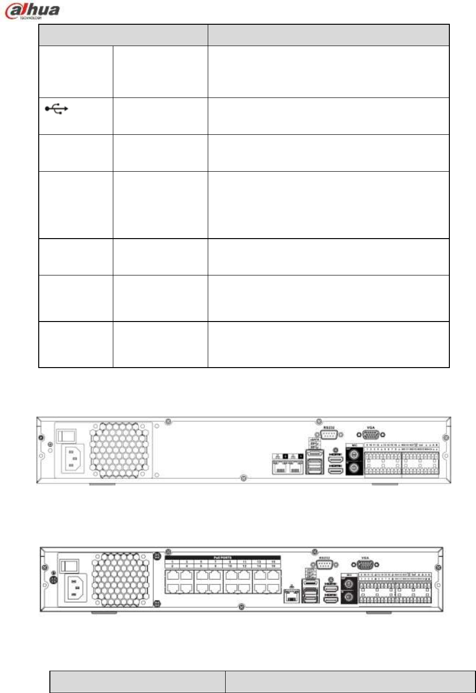
84
Name
Function
eSATA
eSATA port
External SATA port. It can connect to the device of
the SATA port. Please jump the HDD when there is
peripheral connected HDD.
USB2.0 port
USB2.0 port. Connect to mouse, USB storage
device, USB burner and etc.
RS-232
RS232 debug
COM.
It is for general COM debug to configure IP address
or transfer transparent COM data.
HDMI
High Definition
Media Interface
High definition audio and video signal output port. It
transmits uncompressed high definition video and
multiple-channel data to the HDMI port of the
display device. HDMI version is 1.3
VGA
VGA video output
port
VGA video output port. Output analog video signal.
It can connect to the monitor to view analog video.
PoE
PORTS
8 PoE ports
Built-in Switch. Support PoE.
The 8 PoE ports series products supports total 48V
120W power. One PoE port max supports 15W.
PoE
PORTS
16 PoE ports
Built-in Switch. Support PoE. The 16 PoE ports
series products supports total 150W power. One
PoE port max supports 15W.
2.2.14 NVR44-4K/48-4K/54-4KS2/58-4KS2/54-16P-4KS2/58-16P-4KS2 Series
The NVR44-4K/NVR48-4K/ NVR54-4KS2/NVR58-4KS2 series rear panel is shown as below. See Figure
2-52.
Figure 2-52
The NVR54-16P-4KS2/NVR58-16P-4KS2 series rear panel is shown as below. See Figure 2-53.
Figure 2-53
Please refer to the following sheet for detailed information.
Name
Function

85
Name
Function
Power switch
Power on-off button
Power input port
Input AC 100~240V.
Network port
10M/100M/1000Mbps self-adaptive Ethernet port.
Connect to the network cable.
eSATA
eSATA port
External SATA port. It can connect to the device of
the SATA port. Please jump the HDD when there is
peripheral connected HDD.
USB3.0 port
USB3.0 port. Connect to mouse, USB storage
device, USB burner and etc.
HDMI
High Definition
Media Interface
High definition audio and video signal output port. It
transmits uncompressed high definition video and
multiple-channel data to the HDMI port of the display
device. HDMI version is 1.4b.
MIC IN
Audio input port Bidirectional talk input port. It is to receive the analog
audio signal output from the devices such as
microphone, pickup.
MIC OUT
Audio output port
Audio output port. It is to output the analog audio
signal to the devices such as the sound box.
Bidirectional talk output.
Audio output on 1-window video monitor.
Audio output on 1-window video playback.
1~16
Alarm input port
1~16
There are four groups. The first group is from
port 1 to port 4, the second group is from port 5
to port 8, the third group is from 9 to 12, and the
fourth group is from 13 to 16. They are to receive
the signal from the external alarm source. There
are two types; NO (normal open)/NC (normal
close).
When your alarm input device is using external
power, please make sure the device and the
NVR have the same ground.
Ground
Alarm input ground end.
NO1~NO5
Alarm output port
1~5
5 groups of alarm output ports. (Group 1:port
NO1~C1,Group 2:port NO2~C2,Group 3:port
NO3~C3, Group 4:port NO4~C4, Group 5:
port NO5, C5, NC5).Output alarm signal to the
alarm device. Please make sure there is power
to the external alarm device.
NO: Normal open alarm output port.
C: Alarm output public end.
NC: Normal close alarm output port.
C1~C5
NC5
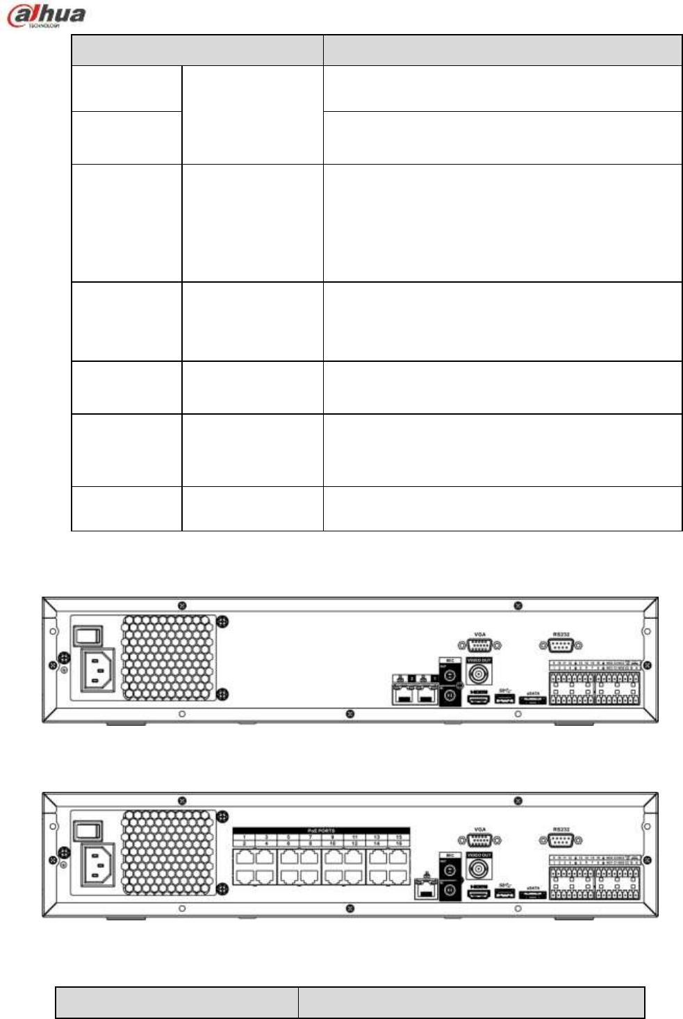
86
Name
Function
A
RS-485
communication
port
RS485_A port. It is the cable A. You can connect to
the control devices such as speed dome PTZ.
B
RS485_B.It is the cable B. You can connect to the
control devices such as speed dome PTZ.
CTRL 12V
/
Controller 12V power output. It is to control the on-off
alarm relay output. It can be used to control the
device alarm output. At the same time, it can also be
used as the power input source of some devices such
as the alarm detector.
+12V
/
+12V power output port. It can provide the power to
some peripheral devices such as the camera or the
alarm device. Please note the supplying power shall
be below 1A.
RS-232
RS232 debug
COM.
It is for general COM debug to configure IP address
or transfer transparent COM data.
VGA
VGA video output
port
VGA video output port. Output analog video signal. It
can connect to the monitor to view analog video.
PoE PORTS
/ Bult-in Switch. Support PoE.
The 16 PoE series product supports total 150W.
2.2.15 NVR48/48-16P Series
The NVR48 series rear panel is shown as below. See Figure 2-54.
Figure 2-54
The NVR48-16P series rear panel is shown as below. See Figure 2-55.
Figure 2-55
Please refer to the following sheet for detailed information.
Name
Function

87
Name
Function
Power switch
/
Power on-off button
Power input
port
/
Input AC 100~240V.
MIC IN
Audio input port
Bidirectional talk input port. It is to receive the
analog audio signal output from the devices such
as microphone, pickup.
MIC OUT
Audio output port
Audio output port. It is to output the analog audio
signal to the devices such as the sound box.
Bidirectional talk output.
Audio output on 1-window video monitor.
Audio output on 1-window video playback.
VIEDEO OUT
Video output port
CVBS output.
1~16
Alarm input port
1~16
There are four groups. The first group is from
port 1 to port 4, the second group is from port 5
to port 8, the third group is from 9 to 12, and
the fourth group is from 13 to 16. They are to
receive the signal from the external alarm
source. There are two types; NO (normal
open)/NC (normal close).
When your alarm input device is using external
power, please make sure the device and the
NVR have the same ground.
GND
Alarm input ground port.
NO1~NO5
Alarm output port
1~5
5 groups of alarm output ports. (Group 1:port
NO1~C1,Group 2:port NO2~C2,Group 3:port
NO3~C3, Group 4:port NO4~C4, Group 5:
port NO5, C5, NC5).Output alarm signal to the
alarm device. Please make sure there is power
to the external alarm device.
NO: Normal open alarm output port.
C: Alarm output public end.
NC: Normal close alarm output port.
C1~C5
NC5
A
RS-485
communication
port
RS485_A port. It is the cable A. You can connect to
the control devices such as speed dome PTZ.
B
RS485_B.It is the cable B. You can connect to the control
devices such as speed dome PTZ.
CTRL 12V
/
Controller 12V power output. It is to control the
on-off alarm relay output. It can be used to control
the device alarm output. At the same time, it can
also be used as the power input source of some
devices such as the alarm detector.
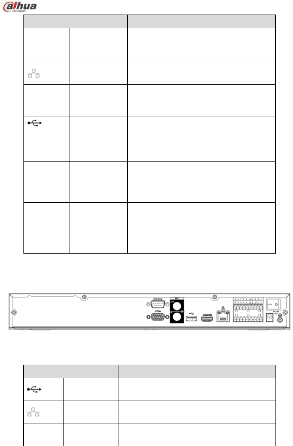
88
Name
Function
+12V
/
+12V power output port. It can provide the power to
some peripheral devices such as the camera or the
alarm device. Please note the supplying power
shall be below 1A.
Network port
One 10M/100M/1000Mbps self-adaptive Ethernet
port. Connect to the network cable.
eSATA
eSATA port
External SATA port. It can connect to the device of
the SATA port. Please jump the HDD when there is
peripheral connected HDD.
USB2.0 port
USB2.0 port. Connect to mouse, USB storage
device, USB burner and etc.
RS-232
RS-232 debug
COM.
It is for general COM debug to configure IP address
or transfer transparent COM data.
HDMI
High Definition
Media Interface
High definition audio and video signal output port. It
transmits uncompressed high definition video and
multiple-channel data to the HDMI port of the
display device. HDMI version is 1.3
VGA
VGA video output
port
VGA video output port. Output analog video signal.
It can connect to the monitor to view analog video.
PoE
PORTS
16 PoE ports
Built-in Switch. Support PoE. The 16 PoE ports
series products supports total 150W power. One
PoE port max supports 15W.
2.2.16 NVR72 Series
The NVR72 series rear panel is shown as below. See Figure 2-56.
Figure 2-56
Please refer to the following sheet for detailed information.
Name
Function
USB2.0 port
USB2.0 port. Connect to mouse, USB storage device,
USB burner and etc.
Network port
10M/100M/1000Mbps self-adaptive Ethernet port.
Connect to the network cable.
RS-232
RS-232 debug
COM.
It is for general COM debug to configure IP address or
transfer transparent COM data.

89
Name
Function
HDMI
High Definition
Media Interface
High definition audio and video signal output port. It
transmits uncompressed high definition video and
multiple-channel data to the HDMI port of the display
device. HDMI version is 1.4.
VGA
VGA video
output port
VGA video output port. Output analog video signal. It
can connect to the monitor to view analog video.
MIC IN
Audio input port
Bidirectional talk input port. It is to receive the analog
audio signal output from the devices such as
microphone, pickup.
MIC OUT
Audio output port
Audio output port. It is to output the analog audio signal
to the devices such as the sound box.
Bidirectional talk output.
Audio output on 1-window video monitor.
Audio output on 1-window video playback.
1~8
Alarm input port
1~8
There are two groups. The first group is from port
1 to port 4; the second group is from port 5 to port
8. They are to receive the signal from the external
alarm source. There are two types; NO (normal
open)/NC (normal close).
When your alarm input device is using external
power, please make sure the device and the NVR
have the same ground.
GND
Alarm input ground port.
NO1~NO3
Alarm output port
1~3
3 groups of alarm output ports. (Group 1:port
NO1~C1,Group 2:port NO2~C2,Group 3:port
NO3~C3)).Output alarm signal to the alarm
device. Please make sure there is power to the
external alarm device.
NO:Normal open alarm output port.
C:Alarm output public end.
C1~C3
A
RS-485
communication
port
RS485_A port. It is the cable A. You can connect to the
control devices such as speed dome PTZ.
B
RS485_B.It is the cable B. You can connect to the
control devices such as speed dome PTZ.
Power input port
Input DC 12V/5A.
Power
switch
/
Power on/off button.
2.2.17 NVR72-8P Series
The NVR72-8P series rear panel is shown as below. See Figure 2-57.
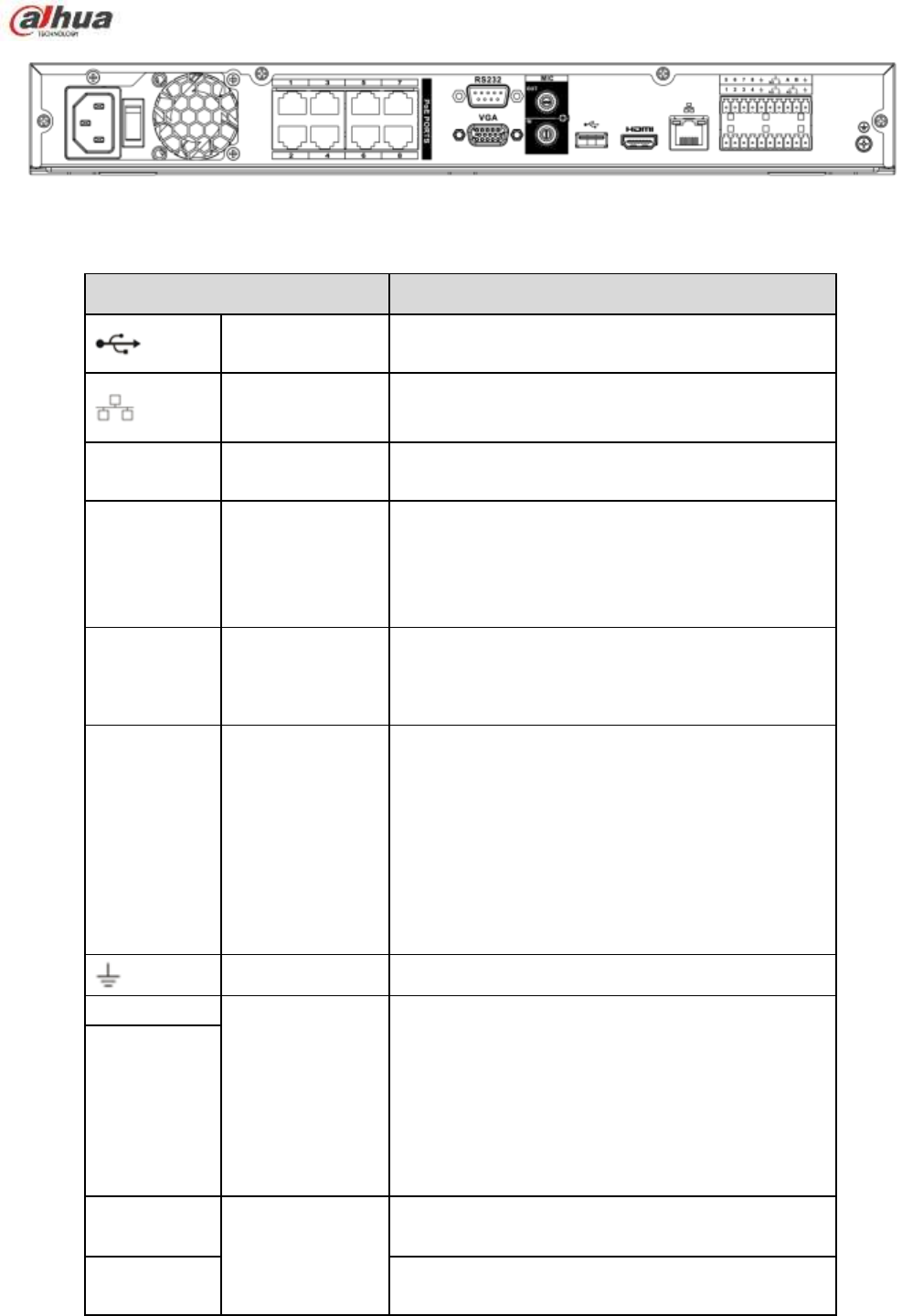
90
Figure 2-57
Please refer to the following sheet for detailed information.
Name
Function
USB2.0 port
USB2.0 port. Connect to mouse, USB storage
device, USB burner and etc.
Network port
10M/100M/1000Mbps self-adaptive Ethernet port.
Connect to the network cable.
RS-232
RS-232 debug
COM.
It is for general COM debug to configure IP
address or transfer transparent COM data.
HDMI
High Definition
Media Interface
High definition audio and video signal output port.
It transmits uncompressed high definition video
and multiple-channel data to the HDMI port of the
display device. HDMI version is 1.4.
VGA
VGA video
output port
VGA video output port. Output analog video
signal. It can connect to the monitor to view analog
video.
1~8
Alarm input port
1~8
There are two groups. The first group is from
port 1 to port 4; the second group is from port
5 to port 8. They are to receive the signal from
the external alarm source. There are two
types; NO (normal open)/NC (normal close).
When your alarm input device is using
external power, please make sure the device
and the NVR have the same ground.
GND
Alarm input ground port.
NO1~NO3
Alarm output port
1~3
3 groups of alarm output ports. (Group 1:port
NO1 ~C1,Group 2:port NO2 ~C2,Group
3:port NO3~C3)).Output alarm signal to the
alarm device. Please make sure there is
power to the external alarm device.
NO:Normal open alarm output port.
C:Alarm output public end.
C1~C3
A
RS-485
communication
port
RS485_A port. It is the cable A. You can connect
to the control devices such as speed dome PTZ.
B
RS485_B.It is the cable B. You can connect to the
control devices such as speed dome PTZ.
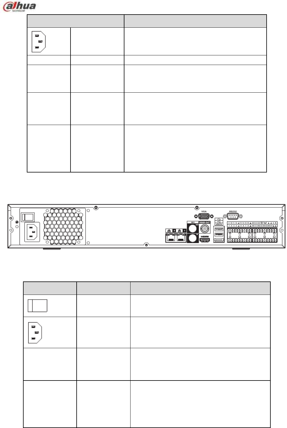
91
Name
Function
Power input port
Input AC 100~240V.
Power switch
/
Power on-off button.
PoE
PORTS
/
Bult-in Switch. Support PoE.
The 8 PoE series product supports total 48V
120W. One PoE port max supports 15W.
MIC IN
Audio input port
Bidirectional talk input port. It is to receive the
analog audio signal output from the devices such
as microphone, pickup.
MIC OUT
Audio output port
Audio output port. It is to output the analog audio
signal to the devices such as the sound box.
Bidirectional talk output.
Audio output on 1-window video monitor.
Audio output on 1-window video playback.
2.2.18 NVR74 Series
The NVR74 series rear panel is shown as below. See Figure 2-58.
Figure 2-58
Please refer to the following sheet for detailed information.
Icon
Name
Function
Power switch
Power on/off button.
Power input port
Input AC 100~240V.
MIC IN
Audio input port
Bidirectional talk input port. It is to receive the
analog audio signal output from the devices such
as microphone, pickup.
MIC OUT
Audio output port
Audio output port. It is to output the analog audio
signal to the devices such as the sound box.
Bidirectional talk output.
Audio output on 1-window video monitor.
Audio output on 1-window video playback.

92
VIEDEO OUT
Video output port CVBS output.
HDMI
High Definition
Media Interface
High definition audio and video signal output port.
It transmits uncompressed high definition video
and multiple-channel data to the HDMI port of the
display device. HDMI version is 1.3.
1~16
Alarm input port
1~16
There are four groups. The first group is from
port 1 to port 4, the second group is from port
5 to port 8, the third group is from 9 to 12,
and the fourth group is from 13 to 16. They
are to receive the signal from the external
alarm source. There are two types; NO
(normal open)/NC (normal close).
When your alarm input device is using
external power, please make sure the device
and the NVR have the same ground.
GND Alarm input ground port.
NO1~NO5
Alarm output port
1~5
5 groups of alarm output ports. (Group 1:
port NO1~C1,Group 2:port NO2~C2,Group
3:port NO3~C3, Group 4:port NO4~C4,
Group 5: port NO5, C5, NC5).Output alarm
signal to the alarm device. Please make sure
there is power to the external alarm device.
NO: Normal open alarm output port.
C: Alarm output public end.
NC: Normal close alarm output port.
C1~C5
NC5
A
RS-485
communication
port
RS485_A port. It is the cable A. You can connect
to the control devices such as speed dome PTZ.
B
RS485_B.It is the cable B. You can connect to
the control devices such as speed dome PTZ.
CTRL 12V
/
Controller 12V power output. It is to control the
on-off alarm relay output. It can be used to control
the device alarm output. At the same time, it can
also be used as the power input source of some
devices such as the alarm detector.
+12V
/
+12V power output port. It can provide the power
to some peripheral devices such as the camera
or the alarm device. Please note the supplying
power shall be below 1A.
Network port
One 10M/100M/1000Mbps self-adaptive Ethernet
port. Connect to the network cable.
eSATA
eSATA port
External SATA port. It can connect to the device
of the SATA port. Please jump the HDD when
there is peripheral connected HDD.
USB2.0 port
USB2.0 port. Connect to mouse, USB storage
device, USB burner and etc.
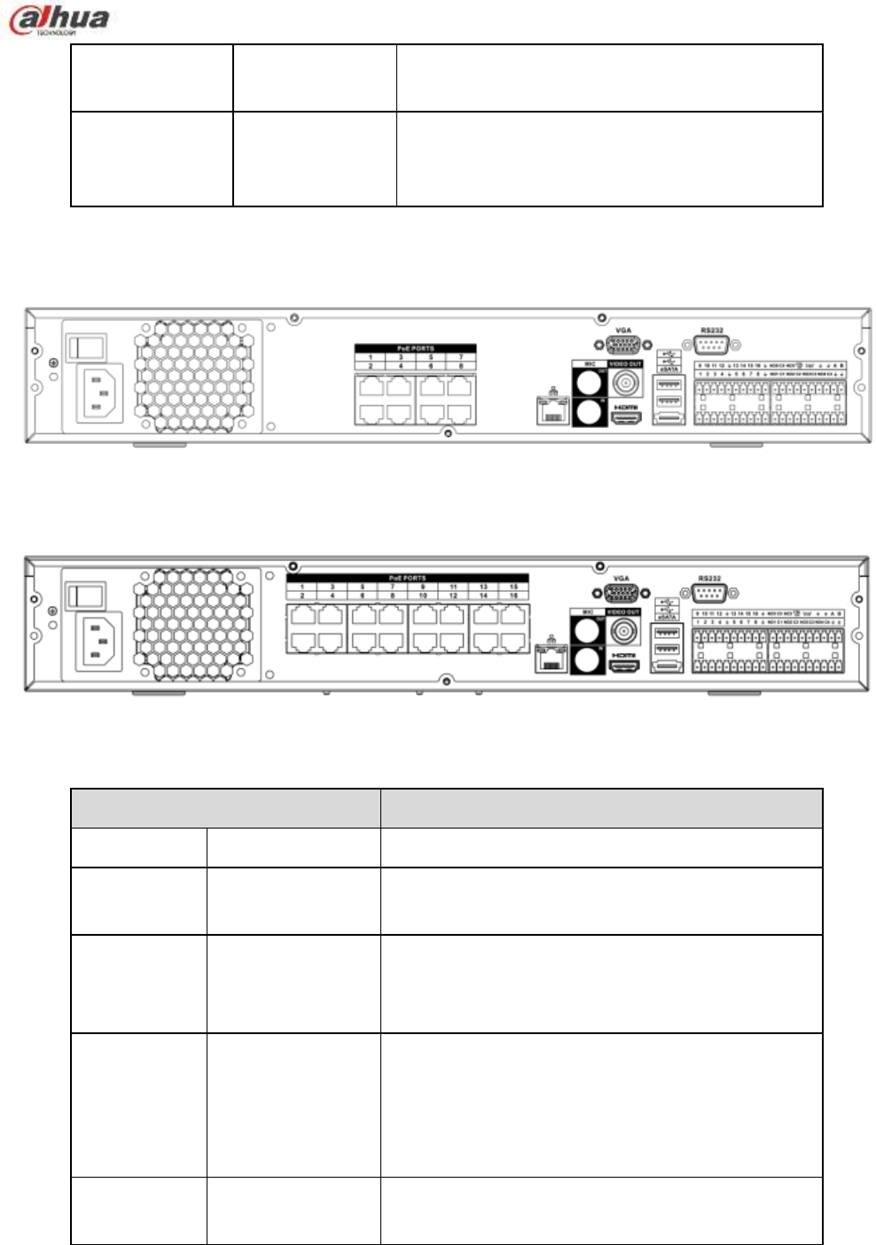
93
RS-232
RS-232 debug
COM.
It is for general COM debug to configure IP
address or transfer transparent COM data.
VGA
VGA video
output port
VGA video output port. Output analog video
signal. It can connect to the monitor to view
analog video.
2.2.19 NVR74-8P/74-16P Series
The NVR74-8P series rear panel is shown as below. See Figure 2-59.
Figure 2-59
The NVR74-16P series rear panel is shown as below. See Figure 2-60.
Figure 2-60
Please refer to the following sheet for detailed information.
Port Name
Function
Power switch
/
Power on-off button
Power input
port
/
Input AC 100~240V.
MIC IN
Audio input port
Bidirectional talk input port. It is to receive the
analog audio signal output from the devices such
as microphone, pickup.
MIC OUT
Audio output port
Audio output port. It is to output the analog audio
signal to the devices such as the sound box.
Bidirectional talk output.
Audio output on 1-window video monitor.
Audio output on 1-window video playback.
VIEDEO
OUT
Video output port
CVBS output

94
Port Name
Function
1~16
Alarm input port
1~16
There are four groups. The first group is from
port 1 to port 4, the second group is from port 5
to port 8, the third group is from 9 to 12, and
the fourth group is from 13 to 16. They are to
receive the signal from the external alarm
source. There are two types; NO (normal
open)/NC (normal close).
When your alarm input device is using external
power, please make sure the device and the
NVR have the same ground.
GND
Alarm input ground port.
NO1~NO5
Alarm output port
1~5
5 groups of alarm output ports. (Group 1:port
NO1~C1,Group 2:port NO2~C2,Group 3:port
NO3~C3, Group 4:port NO4~C4, Group 5:
port NO5, C5, NC5).Output alarm signal to the
alarm device. Please make sure there is power
to the external alarm device.
NO: Normal open alarm output port.
C: Alarm output public end.
NC: Normal close alarm output port.
C1~C5
NC5
A
RS-485
communication
port
RS485_A port. It is the cable A. You can connect to
the control devices such as speed dome PTZ.
B
RS485_B.It is the cable B. You can connect to the
control devices such as speed dome PTZ.
CTRL 12V
/
Controller 12V power output. It is to control the
on-off alarm relay output. It can be used to control
the device alarm output. At the same time, it can
also be used as the power input source of some
devices such as the alarm detector.
+12V
/
+12V power output port. It can provide the power to
some peripheral devices such as the camera or the
alarm device. Please note the supplying power
shall be below 1A.
Network port
10M/100M/1000Mbps self-adaptive Ethernet port.
Connect to the network cable.
eSATA
eSATA port
External SATA port. It can connect to the device of
the SATA port. Please jump the HDD when there is
peripheral connected HDD.
USB2.0 port
USB2.0 port. Connect to mouse, USB storage
device, USB burner and etc.
RS-232
RS232 debug
COM.
It is for general COM debug to configure IP address
or transfer transparent COM data.
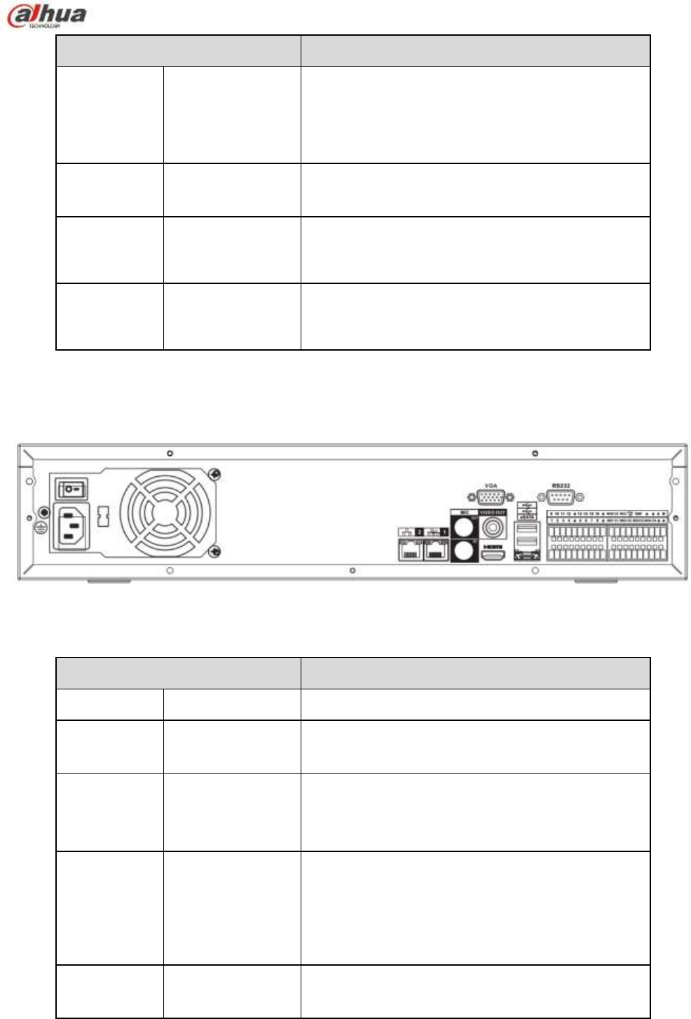
95
Port Name
Function
HDMI
High Definition
Media Interface
High definition audio and video signal output port. It
transmits uncompressed high definition video and
multiple-channel data to the HDMI port of the
display device. HDMI version is 1.3
VGA
VGA video output
port
VGA video output port. Output analog video signal.
It can connect to the monitor to view analog video.
PoE
PORTS
8 PoE ports
Built-in Switch. Support PoE.
The 8 PoE ports series products supports total 48V
120W power. One PoE port max supports 15W.
PoE
PORTS
16 PoE ports
Built-in Switch. Support PoE. The 16 PoE ports
series products supports total 150W power. One
PoE port max supports 15W.
2.2.20 NVR78 Series
The NVR78 series rear panel is shown as below. See Figure 2-61.
Figure 2-61
Please refer to the following sheet for detailed information.
Port Name
Function
Power switch
/
Power on-off button
Power input
port
/
Input AC 100~240V.
MIC IN
Audio input port
Bidirectional talk input port. It is to receive the
analog audio signal output from the devices such
as microphone, pickup.
MIC OUT
Audio output port
Audio output port. It is to output the analog audio
signal to the devices such as the sound box.
Bidirectional talk output.
Audio output on 1-window video monitor.
Audio output on 1-window video playback.
VIEDEO
OUT
Video output port
CVBS output

96
Port Name
Function
1~16
Alarm input port
1~16
There are four groups. The first group is from
port 1 to port 4, the second group is from port 5
to port 8, the third group is from 9 to 12, and
the fourth group is from 13 to 16. They are to
receive the signal from the external alarm
source. There are two types; NO (normal
open)/NC (normal close).
When your alarm input device is using external
power, please make sure the device and the
NVR have the same ground.
GND
Alarm input ground port.
NO1~NO5
Alarm output port
1~5
5 groups of alarm output ports. (Group 1:port
NO1~C1,Group 2:port NO2~C2,Group 3:port
NO3~C3, Group 4:port NO4~C4, Group 5:
port NO5, C5, NC5).Output alarm signal to the
alarm device. Please make sure there is power
to the external alarm device.
NO: Normal open alarm output port.
C: Alarm output public end.
NC: Normal close alarm output port.
C1~C5
NC5
A
RS-485
communication
port
RS485_A port. It is the cable A. You can connect to
the control devices such as speed dome PTZ.
B
RS485_B.It is the cable B. You can connect to the
control devices such as speed dome PTZ.
CTRL 12V
/
Controller 12V power output. It is to control the
on-off alarm relay output. It can be used to control
the device alarm output. At the same time, it can
also be used as the power input source of some
devices such as the alarm detector.
+12V
/
+12V power output port. It can provide the power to
some peripheral devices such as the camera or the
alarm device. Please note the supplying power
shall be below 1A.
Network port
10M/100M/1000Mbps self-adaptive Ethernet port.
Connect to the network cable.
eSATA
eSATA port
External SATA port. It can connect to the device of
the SATA port. Please jump the HDD when there is
peripheral connected HDD.
USB2.0 port
USB2.0 port. Connect to mouse, USB storage
device, USB burner and etc.
RS-232
RS-232 debug
COM.
It is for general COM debug to configure IP address
or transfer transparent COM data.
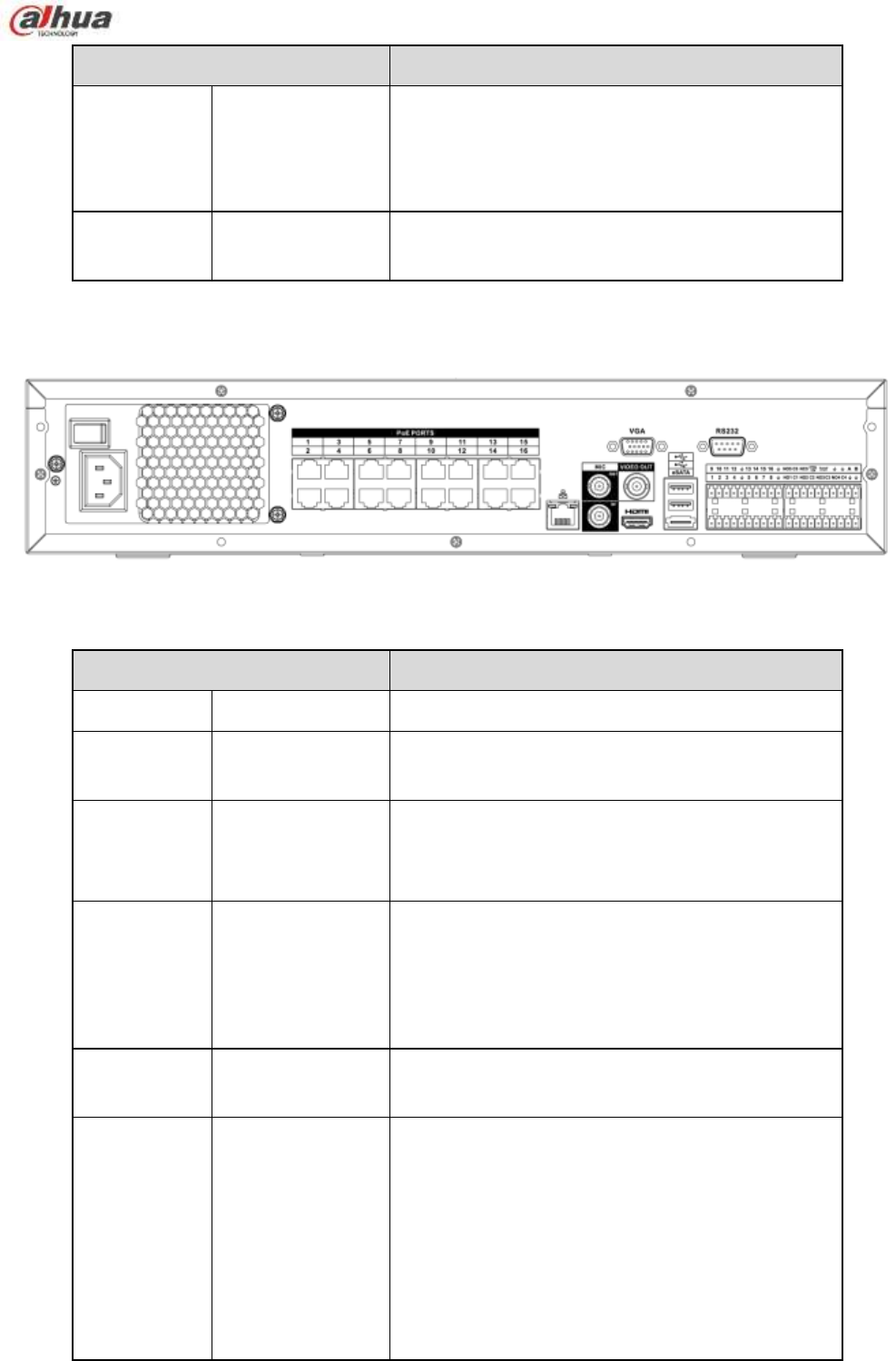
97
Port Name
Function
HDMI
High Definition
Media Interface
High definition audio and video signal output port. It
transmits uncompressed high definition video and
multiple-channel data to the HDMI port of the
display device. HDMI version is 1.3.
VGA
VGA video output
port
VGA video output port. Output analog video signal.
It can connect to the monitor to view analog video.
2.2.21 NVR78-16P Series
The NVR78-16P series rear panel is shown as below. See Figure 2-62.
Figure 2-62
Please refer to the following sheet for detailed information.
Port Name
Function
Power switch
/
Power on-off button
Power input
port
/
Input AC 100~240V.
MIC IN
Audio input port
Bidirectional talk input port. It is to receive the
analog audio signal output from the devices such
as microphone, pickup.
MIC OUT
Audio output port
Audio output port. It is to output the analog audio
signal to the devices such as the sound box.
Bidirectional talk output.
Audio output on 1-window video monitor.
Audio output on 1-window video playback.
VIEDEO
OUT
Video output port
CVBS output
1~16
Alarm input port
1~16
There are four groups. The first group is from
port 1 to port 4, the second group is from port 5
to port 8, the third group is from 9 to 12, and
the fourth group is from 13 to 16. They are to
receive the signal from the external alarm
source. There are two types; NO (normal
open)/NC (normal close).
When your alarm input device is using external
power, please make sure the device and the
NVR have the same ground.

98
Port Name
Function
GND
Alarm input ground port.
NO1~NO5
Alarm output port
1~5
5 groups of alarm output ports. (Group 1:port
NO1~C1,Group 2:port NO2~C2,Group 3:port
NO3~C3, Group 4:port NO4~C4, Group 5:
port NO5, C5, NC5).Output alarm signal to the
alarm device. Please make sure there is power
to the external alarm device.
NO: Normal open alarm output port.
C: Alarm output public end.
NC: Normal close alarm output port.
C1~C5
NC5
A
RS-485
communication
port
RS485_A port. It is the cable A. You can connect to
the control devices such as speed dome PTZ.
B
RS485_B.It is the cable B. You can connect to the
control devices such as speed dome PTZ.
CTRL 12V
/
Controller 12V power output. It is to control the
on-off alarm relay output. It can be used to control
the device alarm output. At the same time, it can
also be used as the power input source of some
devices such as the alarm detector.
+12V
/
+12V power output port. It can provide the power to
some peripheral devices such as the camera or the
alarm device. Please note the supplying power
shall be below 1A.
Network port
10M/100M/1000Mbps self-adaptive Ethernet port.
Connect to the network cable.
eSATA
eSATA port
External SATA port. It can connect to the device of
the SATA port. Please jump the HDD when there is
peripheral connected HDD.
USB2.0 port
USB2.0 port. Connect to mouse, USB storage
device, USB burner and etc.
RS-232
RS232 debug
COM.
It is for general COM debug to configure IP address
or transfer transparent COM data.
HDMI
High Definition
Media Interface
High definition audio and video signal output port. It
transmits uncompressed high definition video and
multiple-channel data to the HDMI port of the
display device. HDMI version is 1.3
VGA
VGA video output
port
VGA video output port. Output analog video signal.
It can connect to the monitor to view analog video.
PoE
PORTS
16 PoE ports
Built-in Switch. Support PoE. The 16 PoE ports
series products supports total 150W power. One
PoE port max supports 15W.
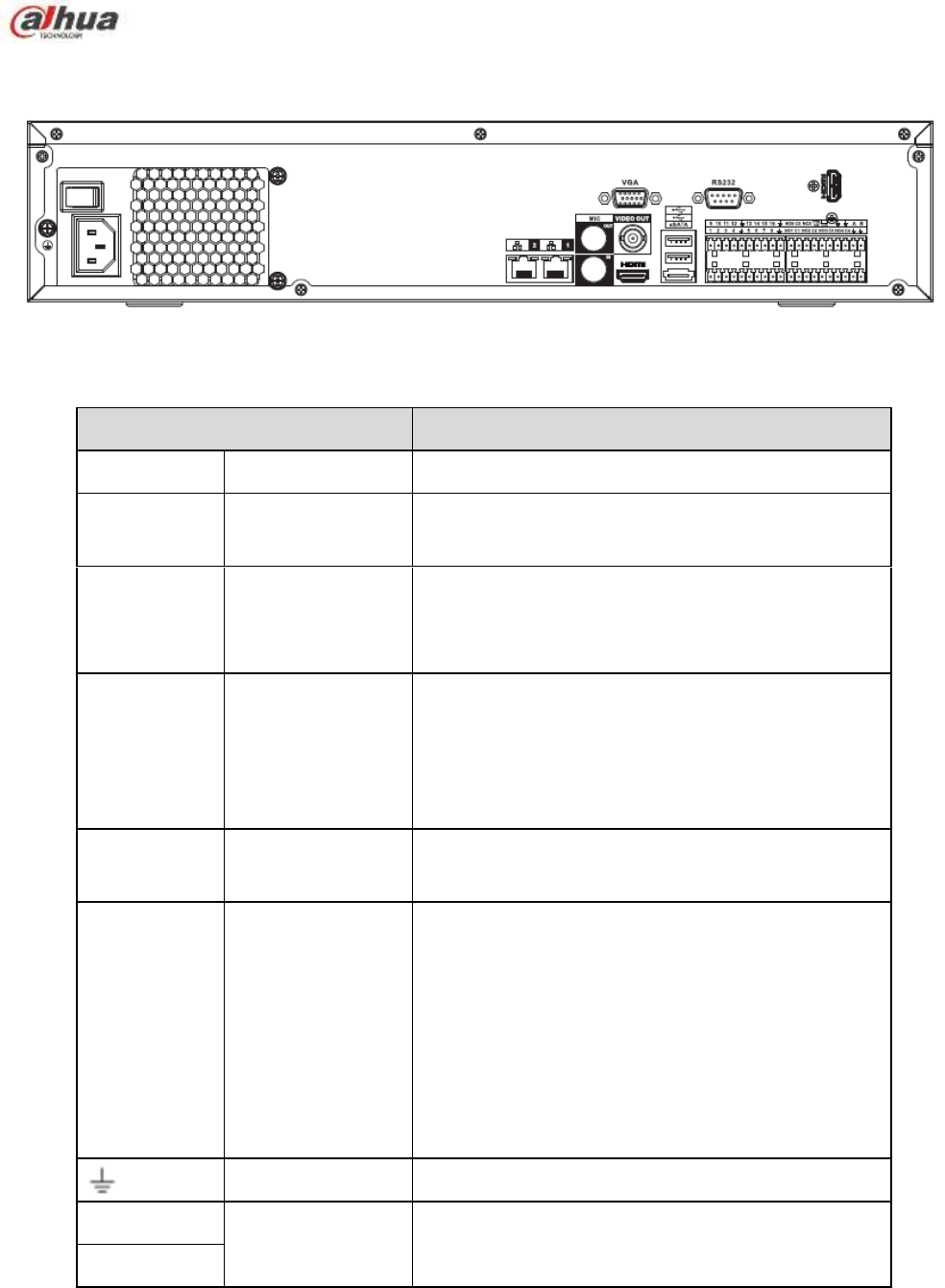
99
2.2.22 NVR78-RH Series
The NVR78-RH series rear panel is shown as below. See Figure 2-63.
Figure 2-63
Please refer to the following sheet for detailed information.
Port Name
Function
Power switch
/
Power on-off button
Power input
port
/
Input AC 100~240V.
MIC IN
Audio input port
Bidirectional talk input port. It is to receive the
analog audio signal output from the devices such
as microphone, pickup.
MIC OUT
Audio output port
Audio output port. It is to output the analog audio
signal to the devices such as the sound box.
Bidirectional talk output.
Audio output on 1-window video monitor.
Audio output on 1-window video playback.
VIEDEO
OUT
Video output port
CVBS output
1~16
Alarm input port
1~16
There are four groups. The first group is from
port 1 to port 4, the second group is from port 5
to port 8, the third group is from 9 to 12, and
the fourth group is from 13 to 16. They are to
receive the signal from the external alarm
source. There are two types; NO (normal
open)/NC (normal close).
When your alarm input device is using external
power, please make sure the device and the
NVR have the same ground.
GND
Alarm input ground port.
NO1~NO5
Alarm output port
1~5
5 groups of alarm output ports. (Group 1:port
NO1~C1,Group 2:port NO2~C2,Group 3:port
C1~C5

100
Port Name
Function
NC5
NO3~C3, Group 4:port NO4~C4, Group 5:
port NO5, C5, NC5).Output alarm signal to the
alarm device. Please make sure there is power
to the external alarm device.
NO: Normal open alarm output port.
C: Alarm output public end.
NC: Normal close alarm output port.
A
RS-485
communication
port
RS485_A port. It is the cable A. You can connect to
the control devices such as speed dome PTZ.
B
RS485_B.It is the cable B. You can connect to the
control devices such as speed dome PTZ.
CTRL 12V
/
Controller 12V power output. It is to control the
on-off alarm relay output. It can be used to control
the device alarm output. At the same time, it can
also be used as the power input source of some
devices such as the alarm detector.
+12V
/
+12V power output port. It can provide the power to
some peripheral devices such as the camera or the
alarm device. Please note the supplying power
shall be below 1A.
Network port
10M/100M/1000Mbps self-adaptive Ethernet port.
Connect to the network cable.
eSATA
eSATA port
External SATA port. It can connect to the device of
the SATA port. Please jump the HDD when there is
peripheral connected HDD.
USB2.0 port
USB2.0 port. Connect to mouse, USB storage
device, USB burner and etc.
RS-232
RS232 debug
COM.
It is for general COM debug to configure IP address
or transfer transparent COM data.
HDMI
High Definition
Media Interface
High definition audio and video signal output port. It
transmits uncompressed high definition video and
multiple-channel data to the HDMI port of the
display device. HDMI version is 1.3. The two HDMI
ports to output video from different video sources.
VGA
VGA video output
port
VGA video output port. Output analog video signal.
It can connect to the monitor to view analog video.
2.2.23 NVR70 Series
The NVR70 series rear panel is shown as below. See Figure 2-64.
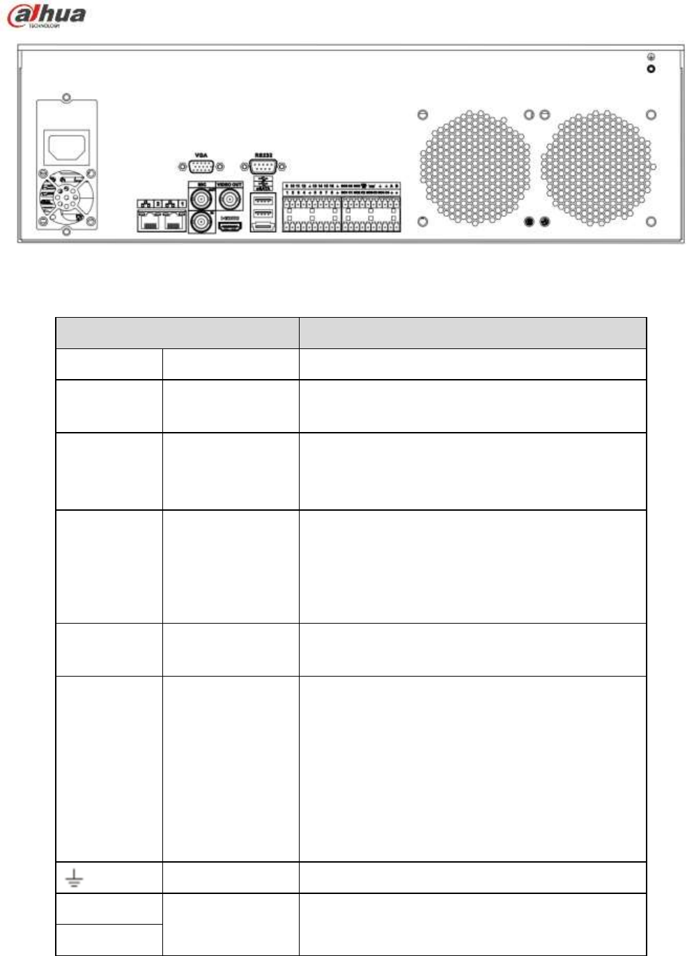
101
Figure 2-64
Please refer to the following sheet for detailed information.
Port Name
Function
Power switch
/
Power on-off button
Power input
port
/
Input AC 100~240V.
MIC IN
Audio input port
Bidirectional talk input port. It is to receive the
analog audio signal output from the devices such
as microphone, pickup.
MIC OUT
Audio output port
Audio output port. It is to output the analog audio
signal to the devices such as the sound box.
Bidirectional talk output.
Audio output on 1-window video monitor.
Audio output on 1-window video playback.
VIEDEO
OUT
Video output port
CVBS output
1~16
Alarm input port
1~16
There are four groups. The first group is from
port 1 to port 4, the second group is from port 5
to port 8, the third group is from 9 to 12, and
the fourth group is from 13 to 16. They are to
receive the signal from the external alarm
source. There are two types; NO (normal
open)/NC (normal close).
When your alarm input device is using external
power, please make sure the device and the
NVR have the same ground.
GND
Alarm input ground port.
NO1~NO5
Alarm output port
1~5
5 groups of alarm output ports. (Group 1:port
NO1~C1,Group 2:port NO2~C2,Group 3:port
C1~C5

102
Port Name
Function
NC5
NO3~C3, Group 4:port NO4~C4, Group 5:
port NO5, C5, NC5).Output alarm signal to the
alarm device. Please make sure there is power
to the external alarm device.
NO: Normal open alarm output port.
C: Alarm output public end.
NC: Normal close alarm output port.
A
RS-485
communication
port
RS485_A port. It is the cable A. You can connect to
the control devices such as speed dome PTZ.
B
RS485_B.It is the cable B. You can connect to the
control devices such as speed dome PTZ.
CTRL 12V
/
Controller 12V power output. It is to control the
on-off alarm relay output. It can be used to control
the device alarm output. At the same time, it can
also be used as the power input source of some
devices such as the alarm detector.
+12V
/
+12V power output port. It can provide the power to
some peripheral devices such as the camera or the
alarm device. Please note the supplying power
shall be below 1A.
Network port
10M/100M/1000Mbps self-adaptive Ethernet port.
Connect to the network cable.
eSATA
eSATA port
External SATA port. It can connect to the device of
the SATA port. Please jump the HDD when there is
peripheral connected HDD.
USB2.0 port
USB2.0 port. Connect to mouse, USB storage
device, USB burner and etc.
RS-232
RS232 debug
COM.
It is for general COM debug to configure IP address
or transfer transparent COM data.
HDMI
High Definition
Media Interface
High definition audio and video signal output port. It
transmits uncompressed high definition video and
multiple-channel data to the HDMI port of the
display device. HDMI version is 1.3
VGA
VGA video output
port
VGA video output port. Output analog video signal.
It can connect to the monitor to view analog video.
2.2.24 NVR70-R Series
The NVR70-R series rear panel is shown as below. See Figure 2-65.
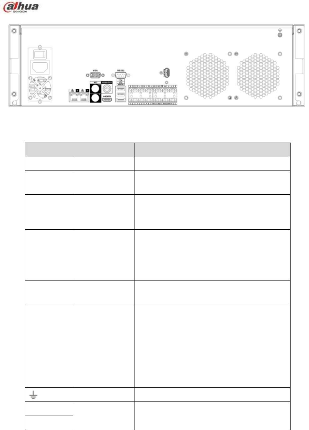
103
Figure 2-65
Please refer to the following sheet for detailed information.
Port Name
Function
Power switch
/
Power on-off button
Power input
port
/
Input AC 100~240V.
MIC IN
Audio input port
Bidirectional talk input port. It is to receive the
analog audio signal output from the devices such
as microphone, pickup.
MIC OUT
Audio output port
Audio output port. It is to output the analog audio
signal to the devices such as the sound box.
Bidirectional talk output.
Audio output on 1-window video monitor.
Audio output on 1-window video playback.
VIEDEO
OUT
Video output port
CVBS output
1~16
Alarm input port
1~16
There are four groups. The first group is from
port 1 to port 4, the second group is from port 5
to port 8, the third group is from 9 to 12, and
the fourth group is from 13 to 16. They are to
receive the signal from the external alarm
source. There are two types; NO (normal
open)/NC (normal close).
When your alarm input device is using external
power, please make sure the device and the
NVR have the same ground.
GND
Alarm input ground port.
NO1~NO5
Alarm output port
1~5
5 groups of alarm output ports. (Group 1:port
NO1~C1,Group 2:port NO2~C2,Group 3:port
C1~C5

104
Port Name
Function
NC5
NO3~C3, Group 4:port NO4~C4, Group 5:
port NO5, C5, NC5).Output alarm signal to the
alarm device. Please make sure there is power
to the external alarm device.
NO: Normal open alarm output port.
C: Alarm output public end.
NC: Normal close alarm output port.
A
RS-485
communication
port
RS485_A port. It is the cable A. You can connect to
the control devices such as speed dome PTZ.
B
RS485_B.It is the cable B. You can connect to the
control devices such as speed dome PTZ.
CTRL 12V
/
Controller 12V power output. It is to control the
on-off alarm relay output. It can be used to control
the device alarm output. At the same time, it can
also be used as the power input source of some
devices such as the alarm detector.
+12V
/
+12V power output port. It can provide the power to
some peripheral devices such as the camera or the
alarm device. Please note the supplying power
shall be below 1A.
Network port
10M/100M/1000Mbps self-adaptive Ethernet port.
Connect to the network cable.
eSATA
eSATA port
External SATA port. It can connect to the device of
the SATA port. Please jump the HDD when there is
peripheral connected HDD.
USB2.0 port
USB2.0 port. Connect to mouse, USB storage
device, USB burner and etc.
RS-232
RS232 debug
COM.
It is for general COM debug to configure IP address
or transfer transparent COM data.
HDMI
High Definition
Media Interface
High definition audio and video signal output port. It
transmits uncompressed high definition video and
multiple-channel data to the HDMI port of the
display device. HDMI version is 1.3. The two HDMI
ports to output video from different video sources.
VGA
VGA video output
port
VGA video output port. Output analog video signal.
It can connect to the monitor to view analog video.
2.2.25 NVR42V-8P Series
The interface is shown as in Figure 2-66.
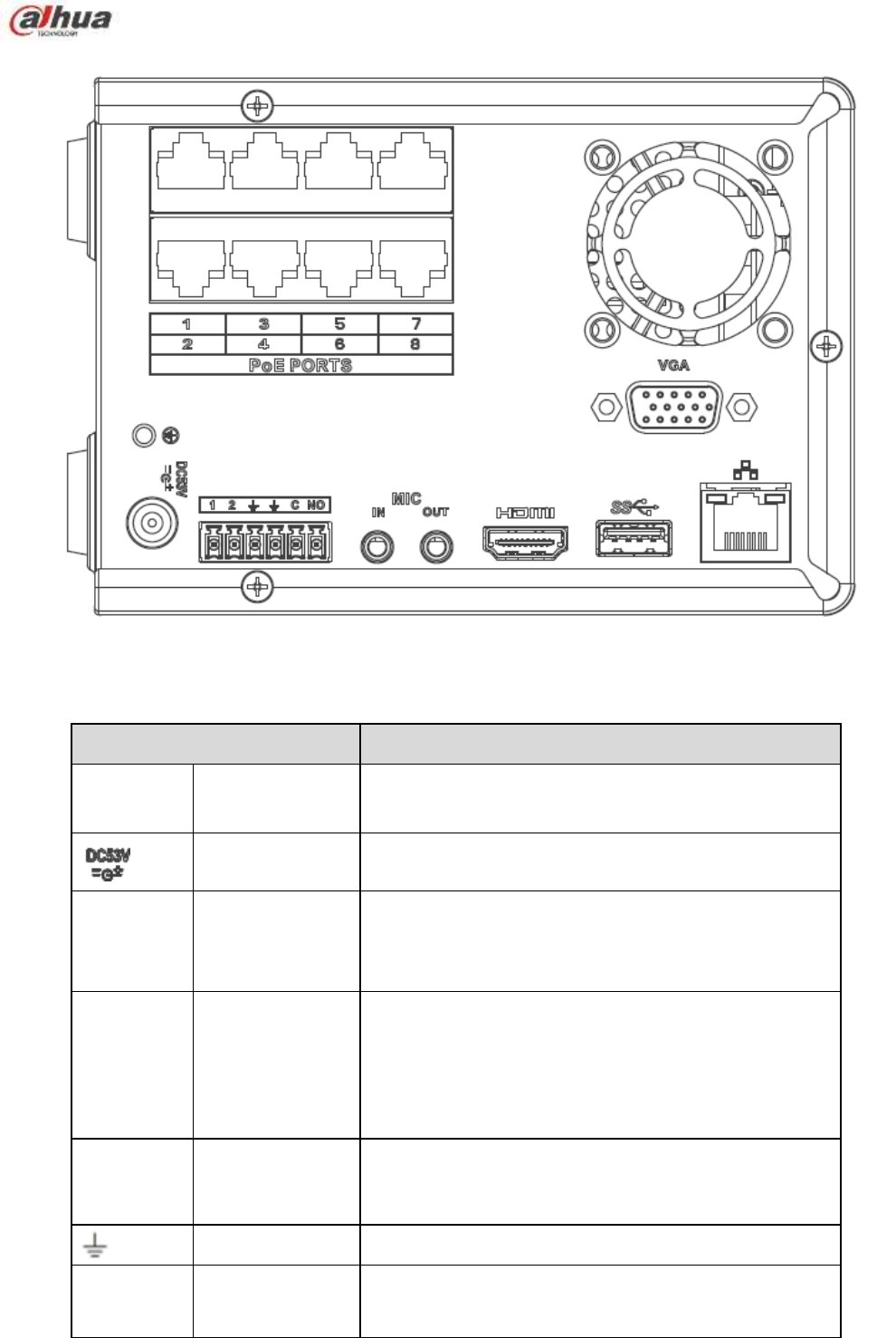
105
Figure 2-66
Please refer to the following sheet for detailed information.
Name
Function
Power
switch
/
Power on/off button.
Power input port
Input DC 53V--2.3A
MIC IN
Audio input port
Bidirectional talk input port. It is to receive the analog
audio signal output from the devices such as
microphone, pickup.
MIC OUT
Audio output port
Audio output port. It is to output the analog audio signal
to the devices such as the sound box.
Bidirectional talk output.
Audio output on 1-window video monitor.
Audio output on 1-window video playback.
1~2
Alarm input port
1~2
When your alarm input device is using external
power, please make sure the device and the NVR
have the same ground.
GND
Alarm input ground port.
C
Alarm output
public port
Alarm output public end.
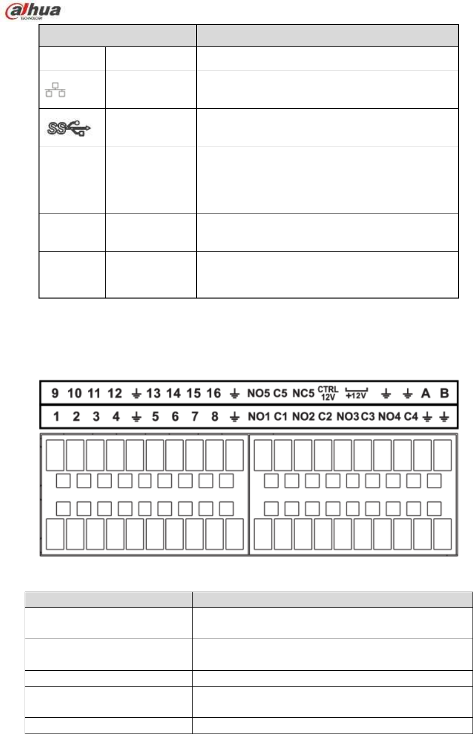
106
Name
Function
NO
Normal open
Normal open alarm output port.
Network port
10M/100M/1000Mbps self-adaptive Ethernet port.
Connect to the network cable.
USB3.0 port
USB3.0 port. Connect to mouse, USB storage device,
USB burner and etc.
HDMI
High Definition
Media Interface
High definition audio and video signal output port. It
transmits uncompressed high definition video and
multiple-channel data to the HDMI port of the display
device. HDMI version is 1.4.
VGA
VGA video
output port
VGA video output port. Output analog video signal. It
can connect to the monitor to view analog video.
PoE
PORT
/
Bult-in Switch. Support PoE.
The 8 PoE series product supports total 48V 120W.
One PoE port max supports 15W.
2.3 Alarm Connection
2.3.1 Alarm Port
The alarm port is shown as below. See Figure 2-67. The following figure is based on the 78 series.
Figure 2-67
Icon
Function
1~16
ALARM1~ALARM16. The alarm becomes activated in the
low level.
NO1 C1,NO2 C2,NO3 C3,NO4
C4
Four NO activation output groups. (On-off button).
NO5 C5 NC5
One NO/NC activation output group. (On-off button).
CTRL 12V
Control power output. Disable power output when alarm is
canceled. Current is 500mA.
+12V
Rated current output. Current is 500mA.
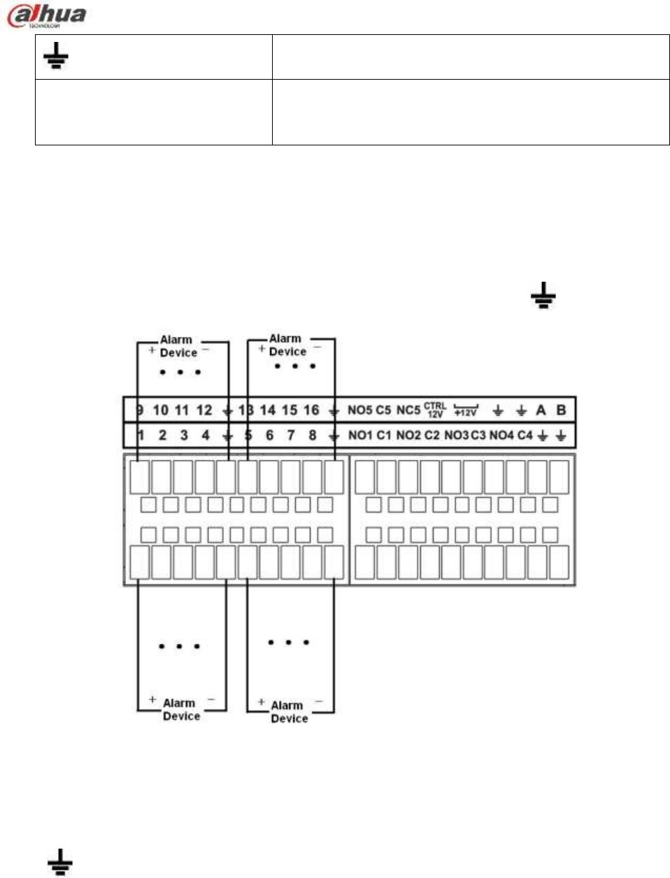
107
GND
A/B
485 communication port. They are used to control devices
such as PTZ. Please parallel connect 120TΩ between A/B
cables if there are too many PTZ decoders.
Note
Different models support different alarm input ports. Please refer to the specifications sheet for
detailed information.
Slight difference may be found on the alarm port layout.
2.3.2 Alarm input port
Connect the positive end (+) of the alarm input device to the alarm input port (ALARM IN 1~16) of the
NVR. Connect the negative end (-) of the alarm input device to the ground end ( ) of the NVR.
Figure 2-68
Note
There are two alarm input types: NO/NC.
When connect the ground port of the alarm device to the NVR, you can use any of the GND ports
().
Connect the NC port of the alarm device to the alarm input port (ALARM) of the NVR.
When there is peripheral power supplying for the alarm device, please make sure it is earthed with
the NVR.
2.3.3 Alarm input and output port
There is peripheral power supplying for the external alarm device.
In case overload may result in NVR damage, please refer to the following relay specifications for
detailed information.
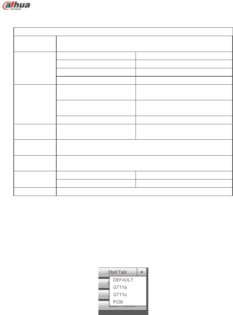
108
A/B cable of the RS485 is for the A/B cable connection of the speed PTZ.
2.3.4 Alarm relay specifications
Model:
JRC-27F
Material of the
touch
Silver
Rating
(Resistance
Load)
Rated switch capacity
30VDC 2A, 125VAC 1A
Maximum switch power
125VA 160W
Maximum switch voltage
250VAC, 220VDC
Maximum switch currency
1A
Insulation
Between touches with same
polarity
1000VAC 1minute
Between touches with different
polarity
1000VAC 1minute
Between touch and winding
1000VAC 1minute
Surge voltage
Between touches with same
polarity
1500V (10×160us)
Length of open
time
3ms max
Length of close
time
3ms max
Longevity
Mechanical
50×106 MIN (3Hz)
Electrical
200×103 MIN (0.5Hz)
Temperature
-40℃ ~+70℃
2.4 Bidirectional talk
2.4.1 Device-end to PC-end
Device Connection
Please connect the speaker or the pickup to the first audio input port in the device rear panel. Then
connect the earphone or the sound box to the audio output port in the PC.
Login the Web and then enable the corresponding channel real-time monitor.
Please refer to the following interface to enable bidirectional talk. See Figure 2-69.
Figure 2-69
Listening Operation
At the device end, speak via the speaker or the pickup, and then you can get the audio from the earphone
or sound box at the pc-end. See Figure 2-70.
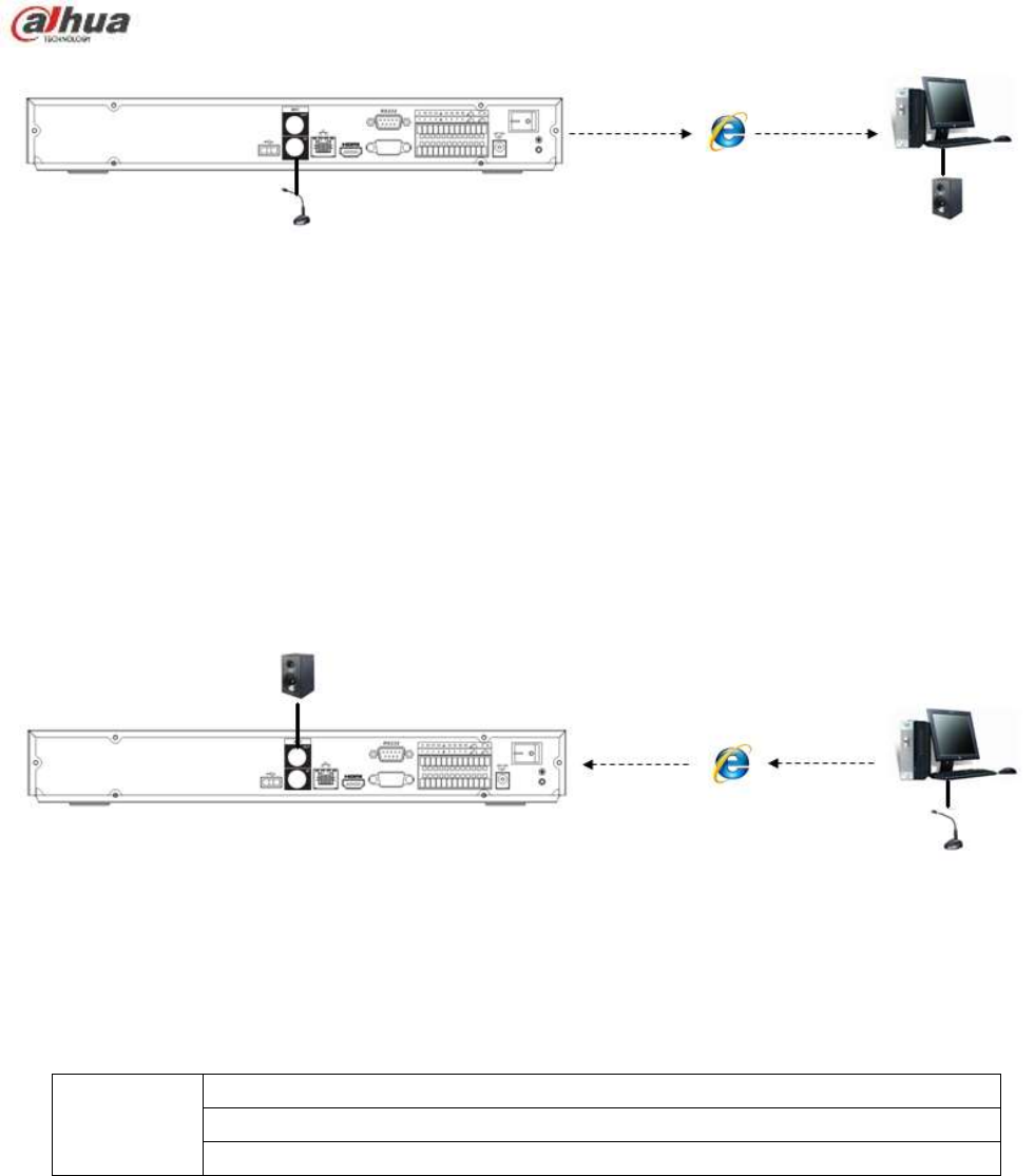
109
Figure 2-70
2.4.2 PC-end to the device-end
Device Connection
Connect the speaker or the pickup to the audio output port in the PC and then connect the earphone or
the sound box to the first audio input port in the device rear panel.
Login the Web and then enable the corresponding channel real-time monitor.
Please refer to the above interface (Figure 2-69) to enable bidirectional talk.
Listening Operation
At the PC-end, speak via the speaker or the pickup, and then you can get the audio from the earphone or
sound box at the device-end. See Figure 2-71.
Figure 2-71
2.5 Mouse Operation
Please refer to the following sheet for mouse operation instruction.
Left click
mouse
When you have selected one menu item, left click mouse to view menu content.
Modify checkbox or motion detection status.
Click combo box to pop up dropdown list
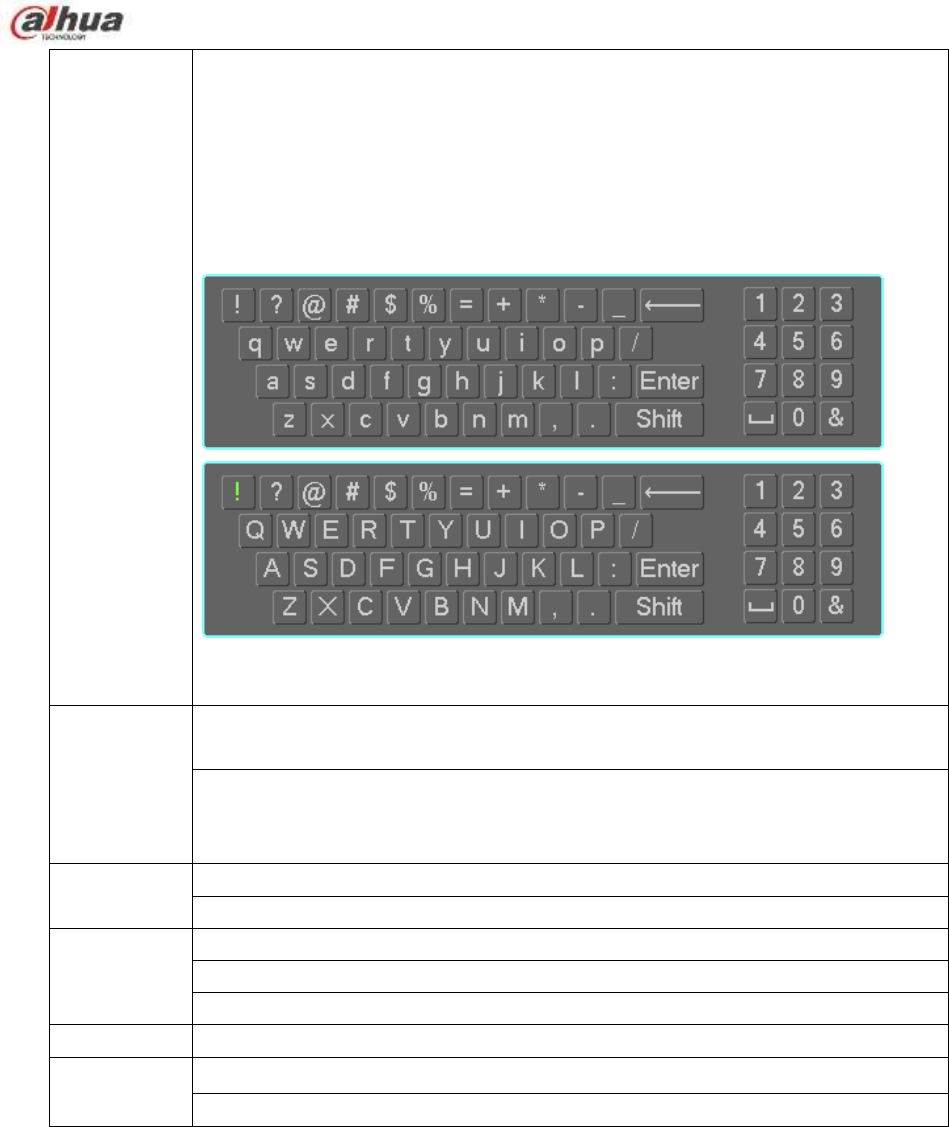
110
In input box, you can select input methods. Left click the corresponding button
on the panel you can input numeral/English character (small/capitalized). Here
← stands for backspace button. _ stands for space button.
In English input mode: _stands for input a backspace icon and ← stands for
deleting the previous character.
In numeral input mode: _ stands for clear and ← stands for deleting the
previous numeral.
Double left
click mouse
Implement special control operation such as double click one item in the file list
to playback the video.
In multiple-window mode, double left click one channel to view in full-window.
Double left click current video again to go back to previous multiple-window
mode.
Right click
mouse
In real-time monitor mode, pops up shortcut menu.
Exit current menu without saving the modification.
Press middle
button
In numeral input box: Increase or decrease numeral value.
Switch the items in the check box.
Page up or page down
Move mouse
Select current control or move control
Drag mouse
Select motion detection zone
Select privacy mask zone.
2.6 Remote Control
The remote control interface is shown as in Figure 2-72.
Please note remote control is not our standard accessory and it is not included in the
accessory bag.
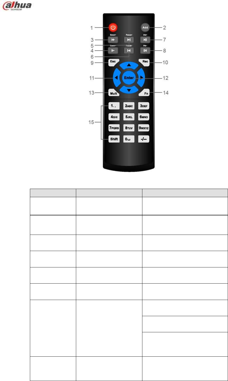
111
Figure 2-72
Serial Number
Name
Function
1
Power button
Click it to boot up or shut down
the device.
2
Address
Click it to input device number, so
that you can control it.
3
Forward
Various forward speeds and
normal speed playback.
4
Slow play
Multiple slow play speeds or
normal playback.
5
Next record
In playback mode, playback the
next video.
6
Previous record
In playback mode, playback the
previous video.
7
Play/Pause
In pause mode, click this button
to realize normal playback.
In normal playback click this
button to pause playback.
In real-time monitor mode, click
this button to enter video search
menu.
8
Reverse/pause
Reverse playback pause mode,
click this button to realize normal
playback.

112
In reverse playback click this
button to pause playback.
9
Esc.
Go back to previous menu or
cancel current operation (close
upper interface or control)
10
Record
Start or stop record manually
In record interface, working with
the direction buttons to select the
record channel.
Click this button for at least 1.5
seconds, system can go to the
Manual Record interface.
11
Direction keys
Switch current activated control,
go to left or right.
In playback mode, it is to control
the playback process bar.
Aux function(such as switch the
PTZ menu)
12
Enter /menu key
go to default button
go to the menu
13
Multiple-window switch
Switch between multiple-window
and one-window.
14
Fn
In 1-ch monitor mode: pop up
assistant function:PTZ control
and Video color.
Switch the PTZ control menu in
PTZ control interface.
In motion detection interface,
working with direction keys to
complete setup.
In text mode, click it to delete
character.
15
0-9 number key
Input password, channel or
switch channel.
Shift is the button to switch the
input method.

113
3 Device Installation
Note: All the installation and operations here should conform to your local electric safety rules.
3.1 Check Unpacked NVR
When you receive the NVR from the forwarding agent, please check whether there is any visible damage.
The protective materials used for the package of the NVR can protect most accidental clashes during
transportation. Then you can open the box to check the accessories.
Please check the items in accordance with the list. Finally you can remove the protective film of the NVR.
3.2 About Front Panel and Rear Panel
The model number in the stick on the bottom of NVR is very important; please check according to your
purchase order.
The label in the rear panel is very important too. Usually we need you to represent the serial number
when we provide the service after sales.
3.3 HDD Installation
Important:
Please turn off the power before you replace the HDD.
The pictures listed below for reference only.
For the first time install, please be aware that whether the HDDs have been installed.
You can refer to the Appendix for HDD space information and recommended HDD brand. Please use
HDD of 7200rpm or higher. Usually we do not recommend the PC HDD.
Please follow the instructions below to install hard disk.
3.3.1 NVR100/100-P Series
Please make sure the metal surface of the HDD is facing up when you are installing!
This series NVR has only one 2.5-inch SATA HDD.
Please follow the instructions below to install HDD.
○
1Draw out the HDD bracket
○
2Make sure the HDD metal
surface is facing up and then put
the HDD into the bracket
○
3Put the HDD into the device.
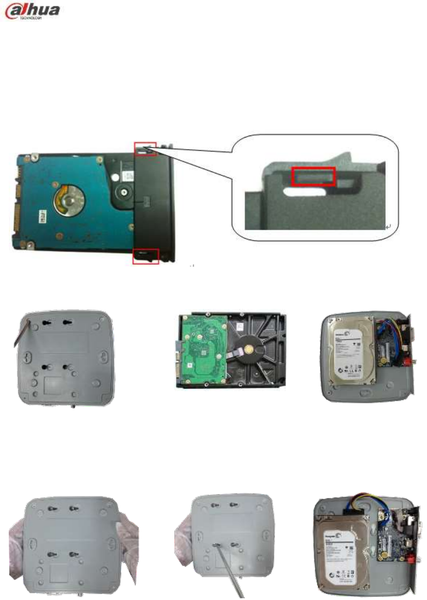
114
horizontally. After the HDD is in
the proper position, the columns
on the two sides can lock the
screw holes of the HDD to secure
it.
When you remove the HDD, please refer to the following figure to pull the spring up and then remove the
HDD.
3.3.2 NVR11/11-P/41/41-P/41-8P/41-W/21-S2/21-P-S2/21-8P-S2 Series
○
1. Loosen the screws of the upper
cover and side panel.
○
2 Fix four screws in the HDD
(Turn just three rounds).
○
3 Place the HDD in
accordance with the four holes in
the bottom.
○
4 Turn the device upside down and
then turn the screws in firmly.
○
5 Fix the HDD firmly.
○
6 Connect the HDD cable and
power cable.
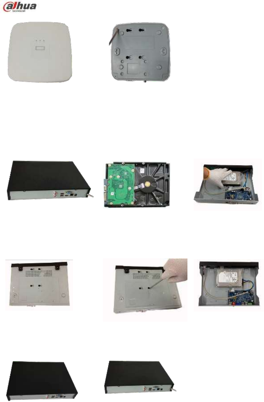
115
○
7 Put the cover in accordance with
the clip and then place the upper cover
back.
○
8 Secure the screws in the rear panel and the side panel.
3.3.3 NVR11H/11H-P/41H/41H-P/41H-8P/11HS/21HS-S2/21HS-P-S2/21HS-8P-S2/
41HS-W-S2 Series
○
1. Loosen the screws of the upper
cover and side panel.
○
2 Fix four screws in the HDD
(Turn just three rounds).
○
3 Place the HDD in
accordance with the four holes
in the bottom.
○
4 Turn the device upside down and
then turn the screws in firmly.
○
5 Fix the HDD firmly.
○
6 Connect the HDD cable
and power cable.
○
7 Put the cover in accordance with
the clip and then place the upper cover
back.
○
8 Secure the screws in the rear panel and the side panel.
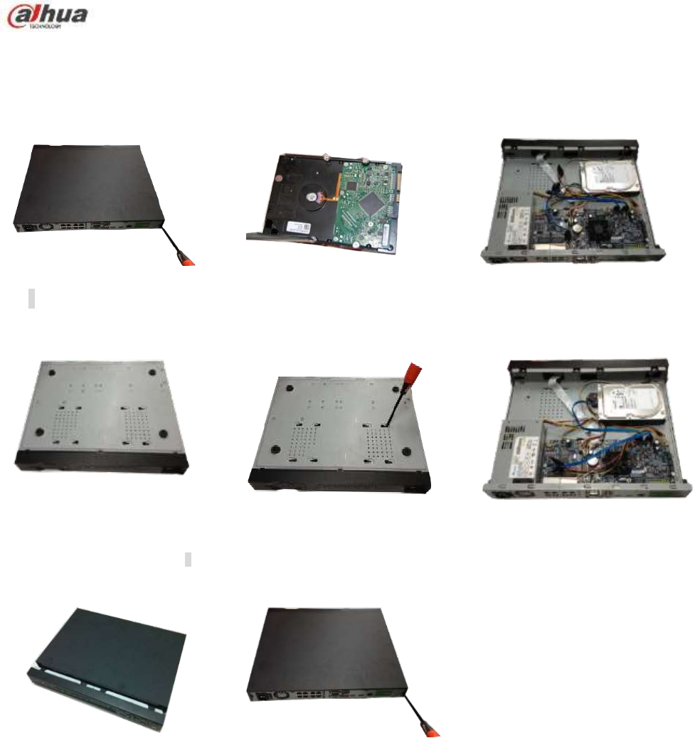
116
3.3.4 NVR42/42N/42-P/42-8P/42-16P/72/72-8P/42-4K/42-8P-4K/52-4KS2/52-8P-4KS2/52
-16P-4KS2/22-S2/22-P-S2/22-8P-S2 Series
The following figures are based on the NVR 72-8P series.
○
1 Loosen the screws of the upper
cover and side panel.
②Fix four screws in the HDD (Turn
just three rounds).
③Place the HDD in accordance with
the four holes in the bottom.
④Turn the device upside down and
then turn the screws in firmly.
⑤Fix the HDD firmly.
⑥Connect the HDD cable and power
cable.
⑦Put the cover in accordance with
the clip and then place the upper cover
back.
⑧Secure the screws in the rear panel
and the side panel.
3.3.5 NVR44/44-8P/44-16P/74/74-8P/74-16P/44-4K/54-4KS2/54-16P-4KS2 Series
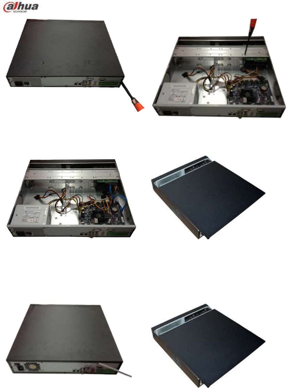
117
① Use the screwdriver to loose the screws of the rear
panel and then remove the front cover.
② Put the HDD to the HDD bracket in the chassis
and then line up the four screws to the four holes
in the HDD. Use the screwdriver to fix the screws
firmly to secure HDD on the HDD bracket
③ Connect to the HDD data cable to the main board
and the HDD port respectively. Loosen the power
cable of the chassis and connect another end of the
power cable to the HDD port.
④ After connect the cable, put the front cover back to
the device and then fix screws of the rear panel.
3.3.6 NVR48/48-16P/NVR78/78-16P/48-4K/58-4KS2/58-16P-4KS2 Series
The following figures are based on the NVR78 series.
① ①Use the screwdriver to loose the screws
of the rear panel and then remove the front
cover.
② ②Put the HDD to the HDD bracket in
the chassis and then line up the four
screws to the four holes in the HDD.
Use the screwdriver to fix the screws
firmly to secure HDD on the HDD
bracket
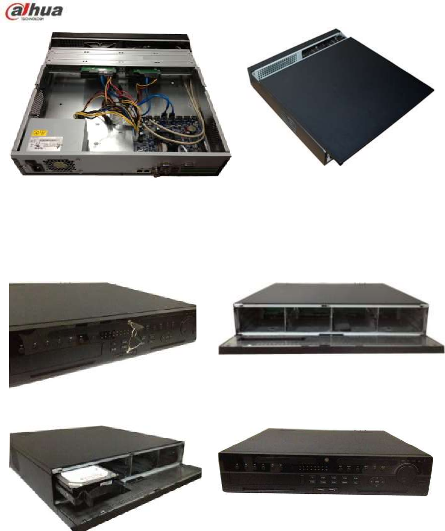
118
③Connect to the HDD data cable to the main board
and the HDD port respectively. Loosen the power cable
of the chassis and connect another end of the power
cable to the HDD port.
④After connect the cable, put the front cover
back to the device and then fix screws of the rear
panel.
3.3.7 NVR78-RH Series
①Turn the key into the hole in the front
panel.
②Open the front panel.
③ Put the HDD to the slot and adjust the
handle to secure it.
④Put the front panel back and use the key to fix
firmly.
HDD Handle Installation
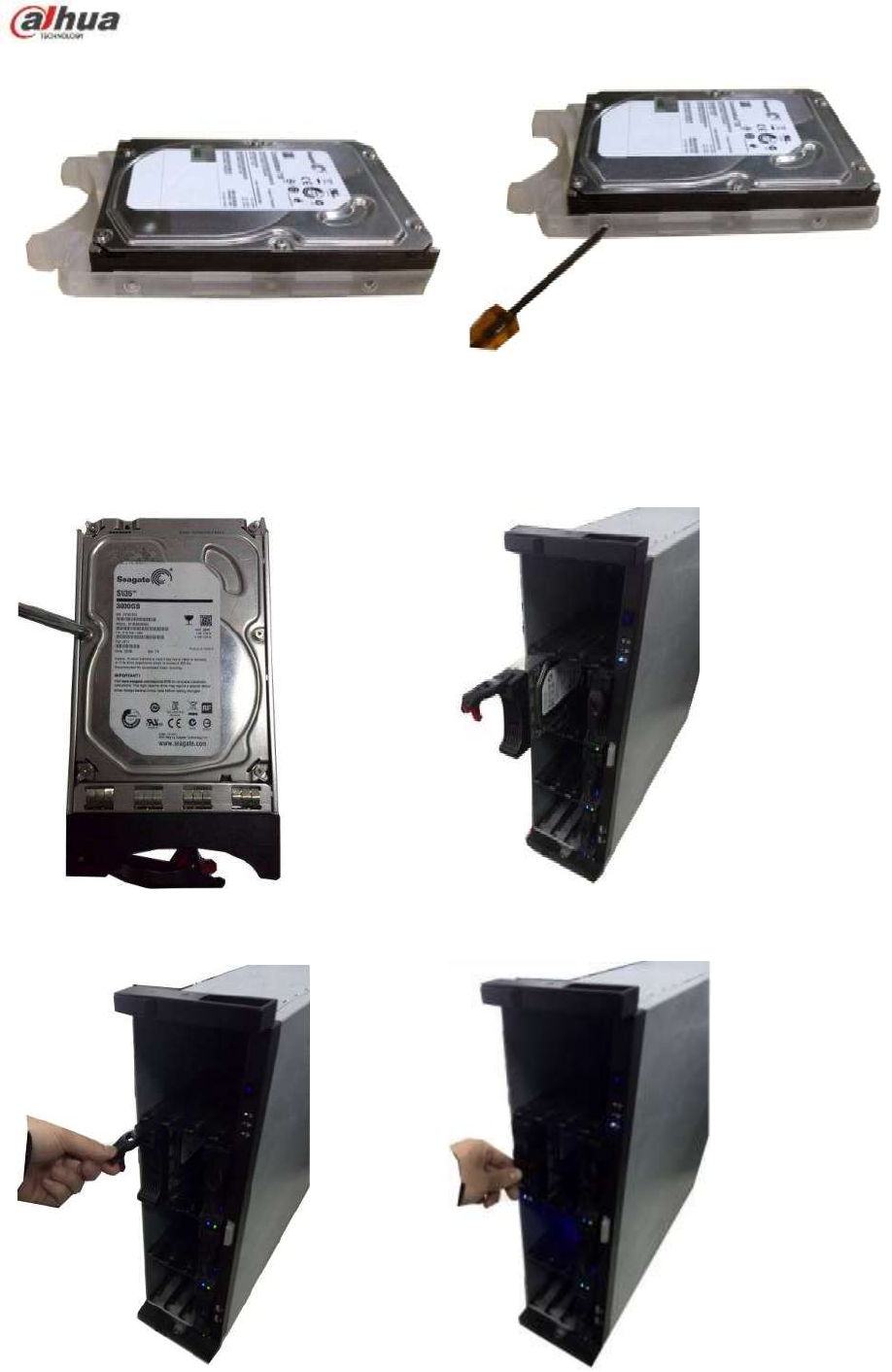
119
①Line up the handle to the HDD side (without
the interface)
②Use the screwdriver to fix the handle on the
HDD.
3.3.8 NVR70/70-R Series
①Use four screws to secure the HDD.
②Put the HDD to the HDD box at the front
panel of the device. .
③Please pull the handle up when you are
inputing the HDD box in case the the handle
④Put the HDD to the HDD box at the front
panel of the device. .
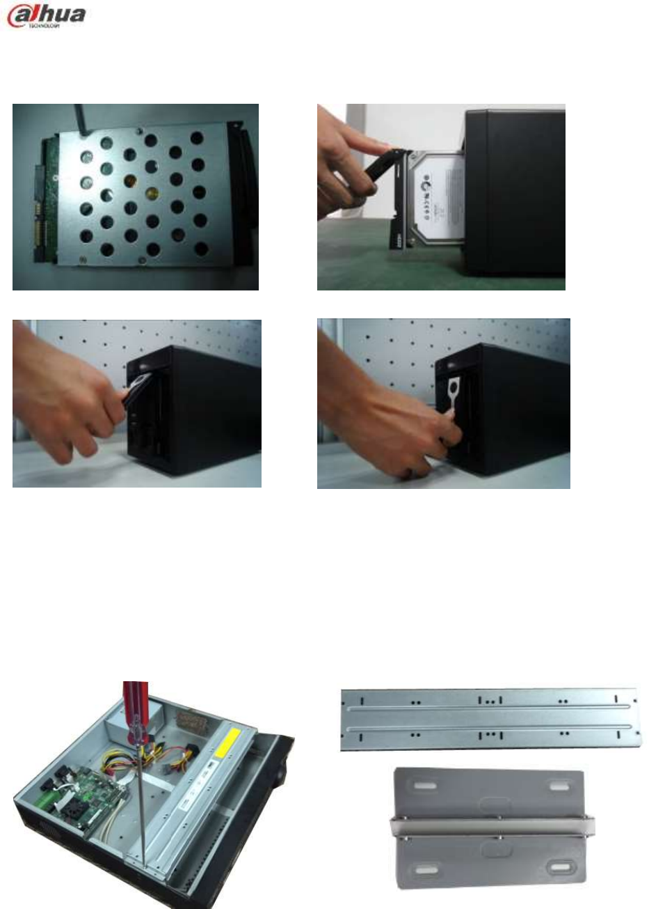
120
collides with the front panel
3.3.9 NVR42V-8P Series
①Use 4 screws to secure the HDD
②Put the HDD to the HDD box at the front.
③Pull the HDD knob up when you put the HDD
into the box in case the knob buckle may strike
the front panel.
④Put the knob back after you insert the HDD
to the SATA board.
.
3.4 CD-ROM Installation
Please follow the steps listed below.
① Open top cover and then remove the
HDD bracket
② Take off the bottom of the HDD bracket and CD-ROM
bracket.
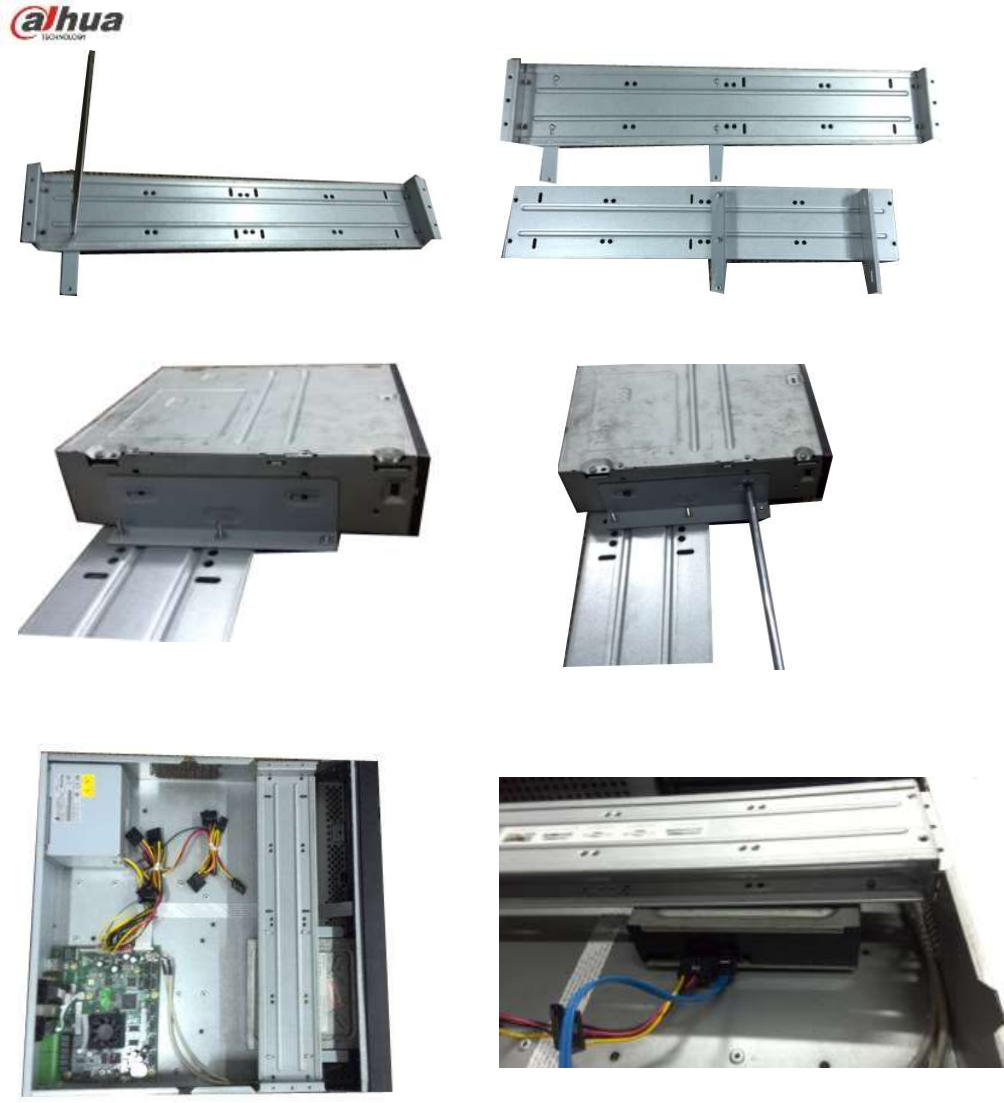
121
③ Fix the CD-ROM bracket at the HDD
bracket.
④ Install a pair of the CD-ROM bracket. Please make
sure the reverse side is secure too.
⑤ Install SATA burner. Line up the SATA
burner to the hole positions.
⑥ User screwdriver to fix the screws.
⑦ Put the bracket back. Please adjust the
CD-ROM to the proper position so that
the button of the front panel is directly
facing the pop-up button of the CD-ROM.
⑧ Connect the SATA cable and power wire.
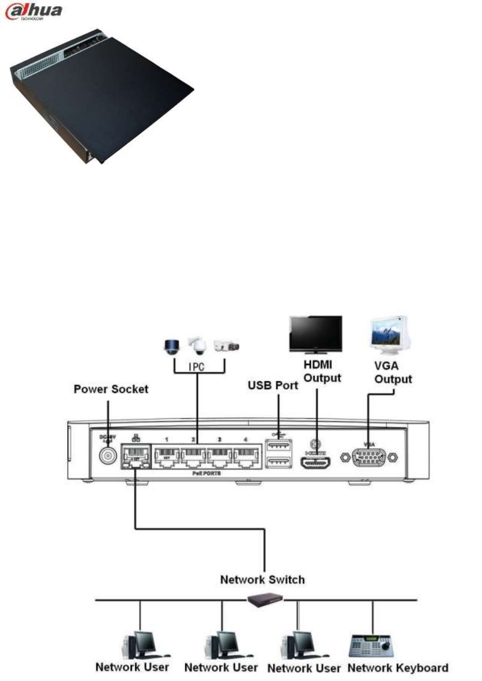
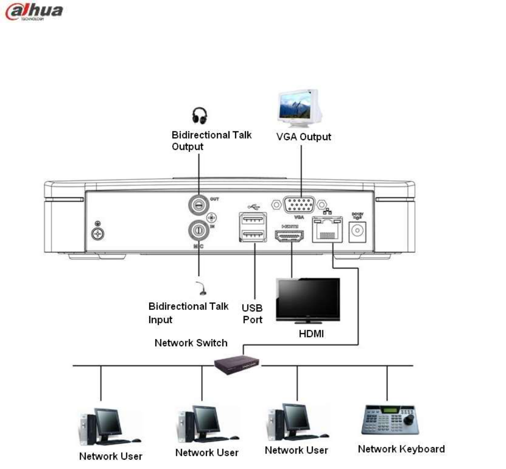
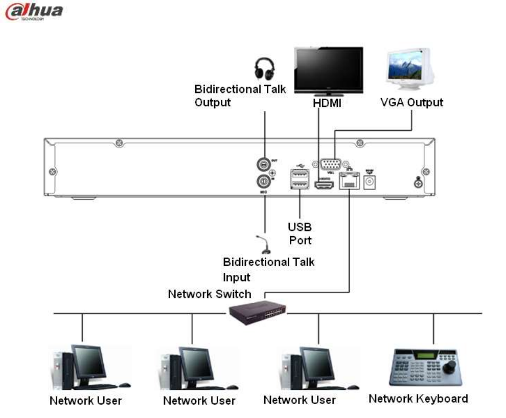
124
Figure 3-3
3.5.4 NVR11HS//41HS-W-S2 Series
Please refer to Figure 3-4 for connection sample.
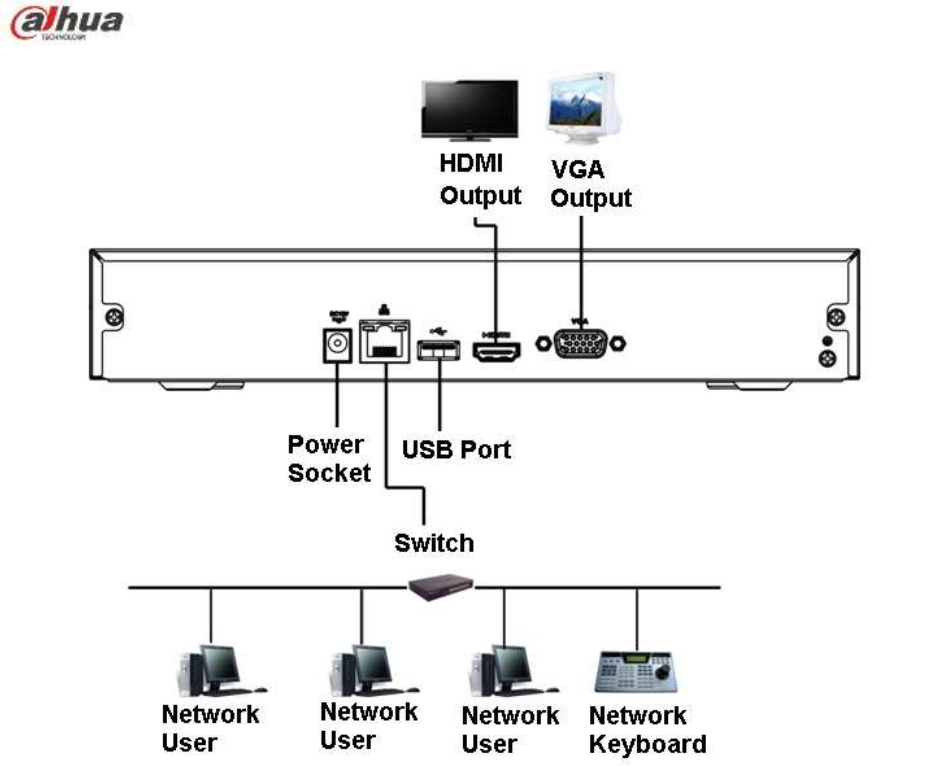
125
Figure 3-4
3.5.5 NVR41HS-W-S2 Series
Please refer to Figure 3-5 for connection sample.
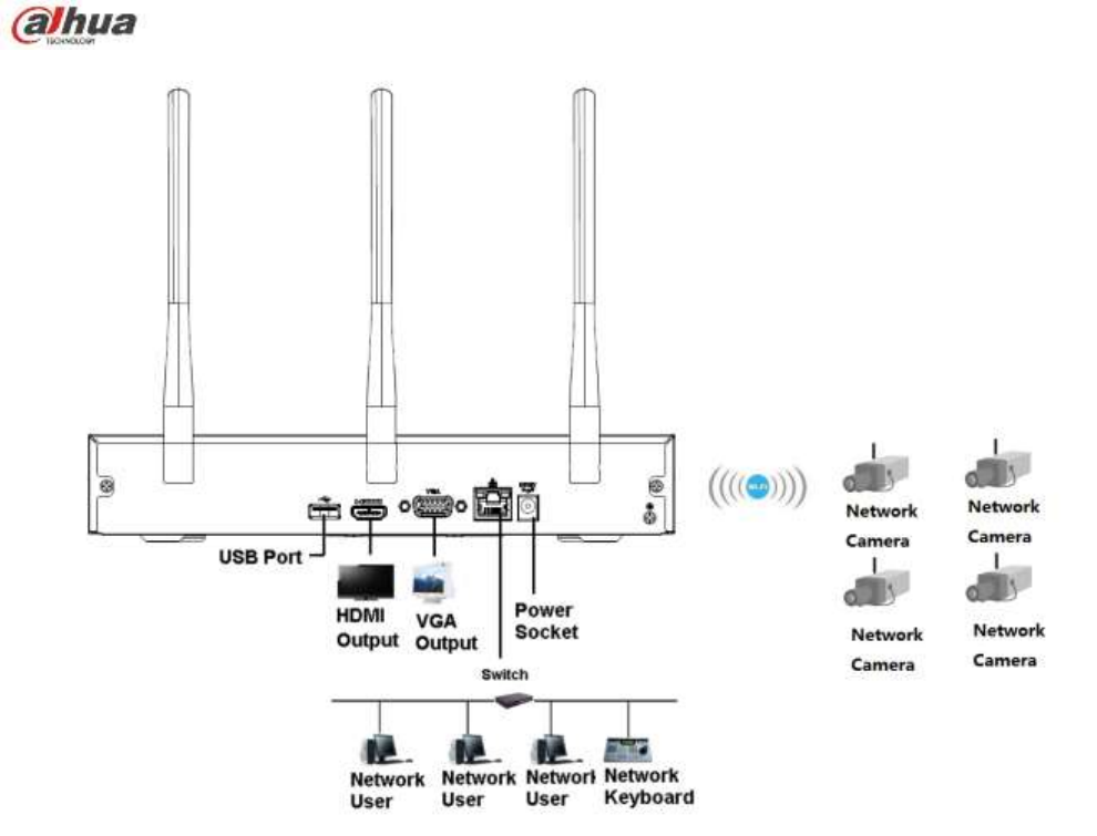
126
Figure 3-5
3.5.6 NVR21HS-S2/21HS-P-S2/21HS-8P-S2 Series
Please refer to Figure 3-6 for connection sample.
Please note the following figure is based on the NVR21HS-8P-S2.

127
Figure 3-6
3.5.7 NVR22-S2/22-P-S2/22-8P-S2 Series
Please refer to Figure 3-7 for connection sample.
Please note the following figure is based on the NVR22-8P-S2.
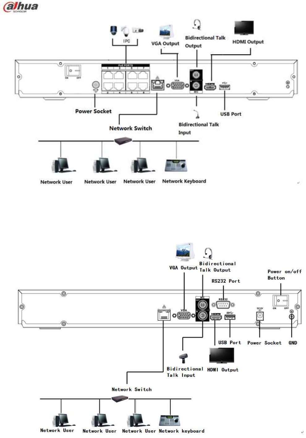
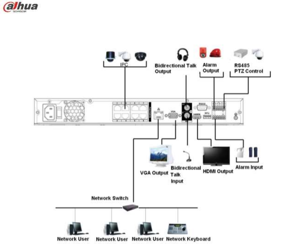
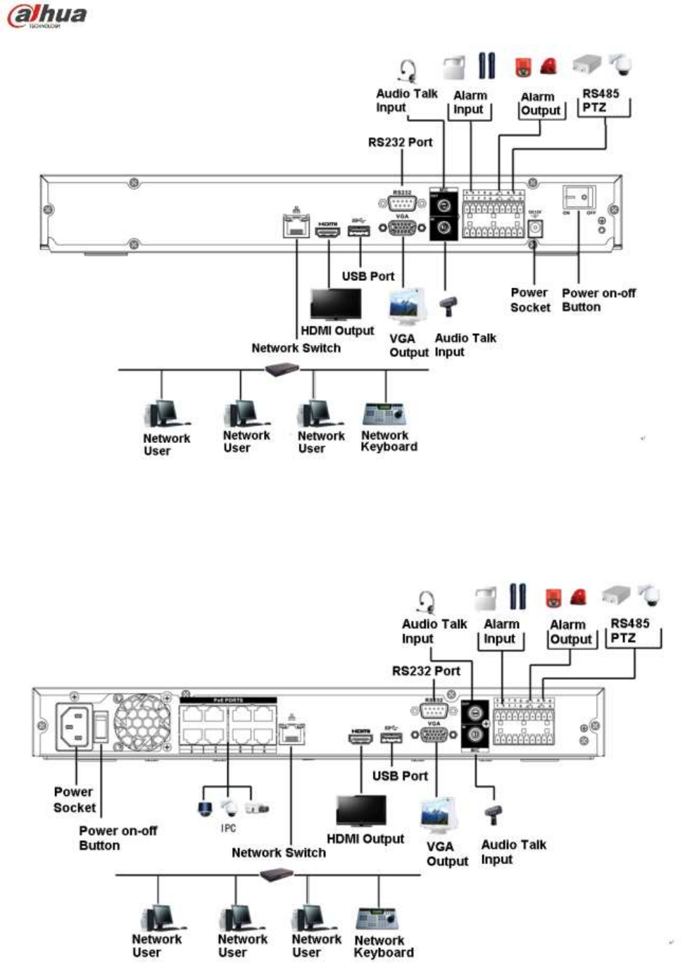
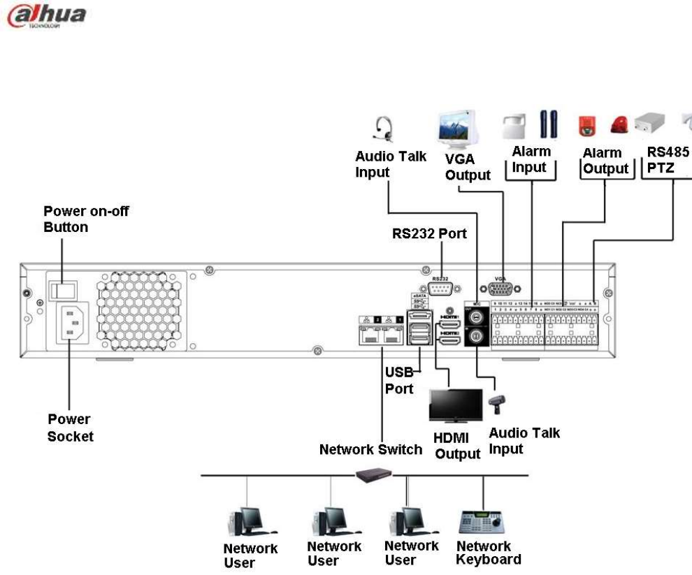
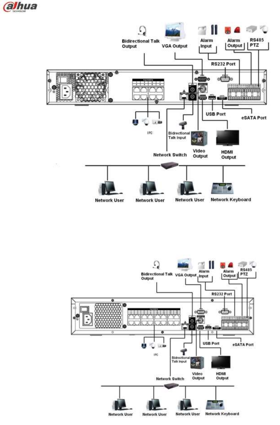
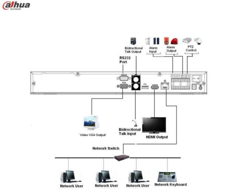
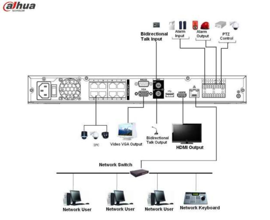
134
Figure 3-16
3.5.17 NVR74 Series
Please refer to Figure 3-17 for connection sample.
The following figure is based on the 74 series product.
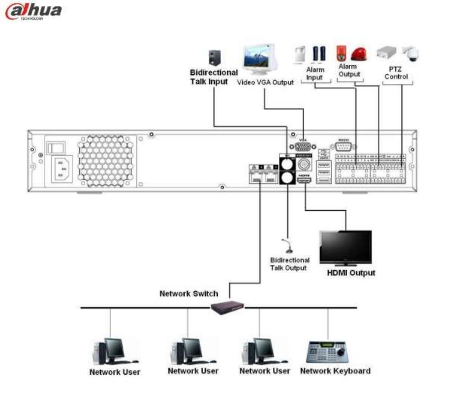
135
Figure 3-17
3.5.18 NVR74-8P/74-16P Series
Please refer to Figure 3-18 for connection sample.
The following figure is based on the NVR74-8P series product.
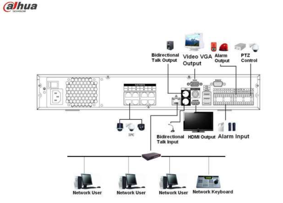
136
Figure 3-18
3.5.19 NVR78 Series
Please refer to Figure 3-19 for connection sample.
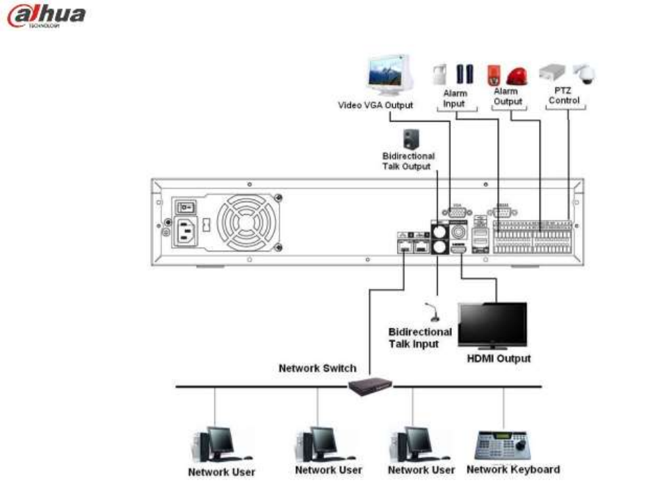
137
Figure 3-19
3.5.20 NVR78-16P Series
Please refer to Figure 3-20 for connection sample.
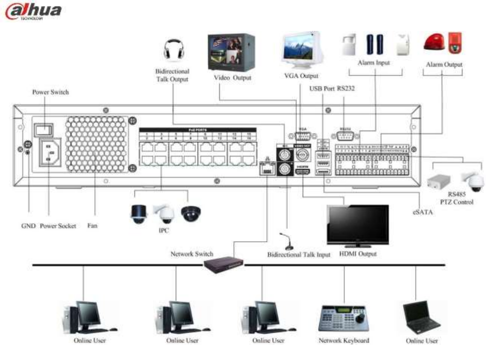
138
Figure 3-20
3.5.21 NVR78-RH Series
Please refer to Figure 3-21 for connection sample.
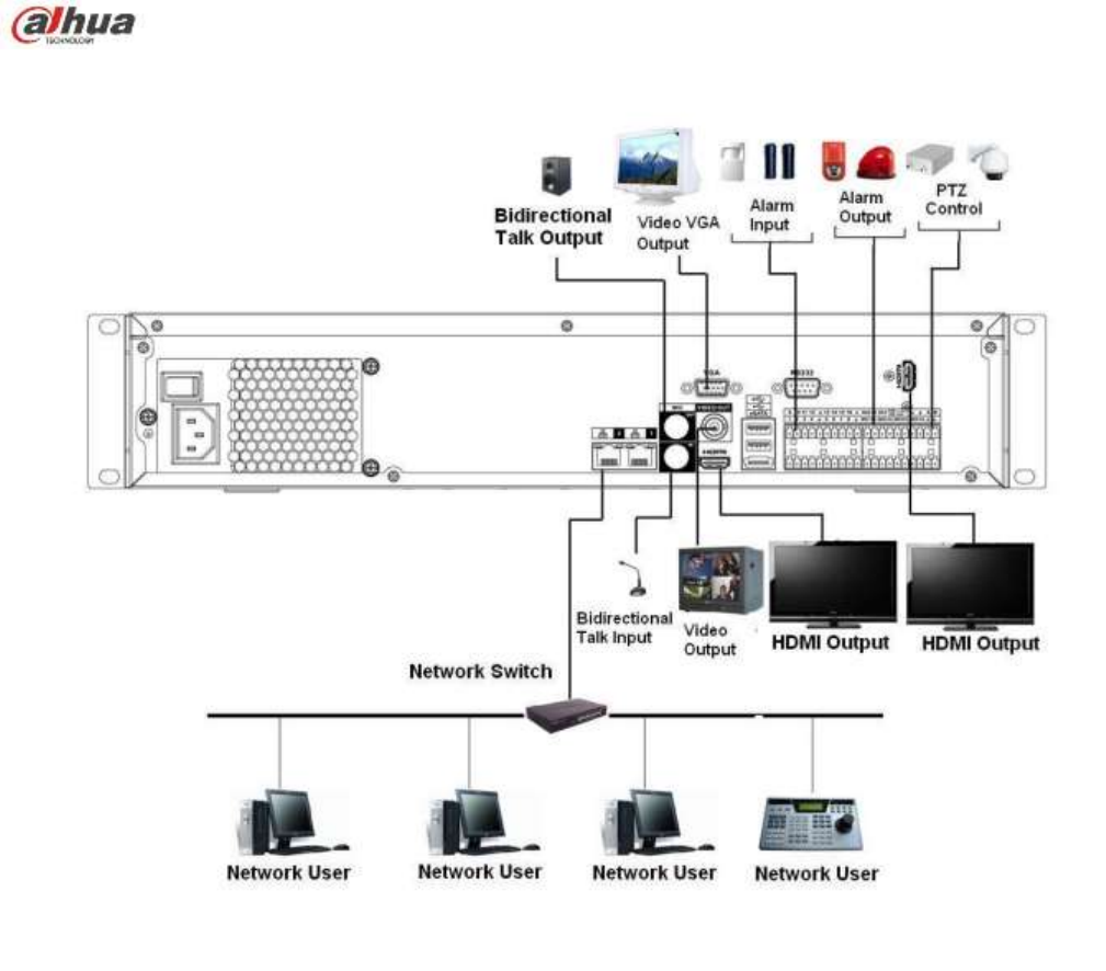
139
Figure 3-21
3.5.22 NVR70 Series
Please refer to Figure 3-22 for connection sample.
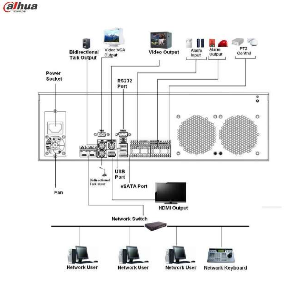
140
Figure 3-22
3.5.23 NVR70-R Series
Please refer to Figure 3-23 for connection sample.
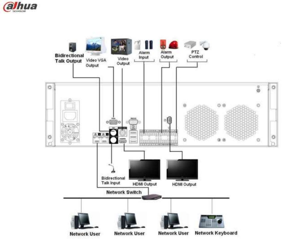
141
Figure 3-23
3.5.24 NVR42V-8P Series
Please refer to Figure 3-24 for connection sample.
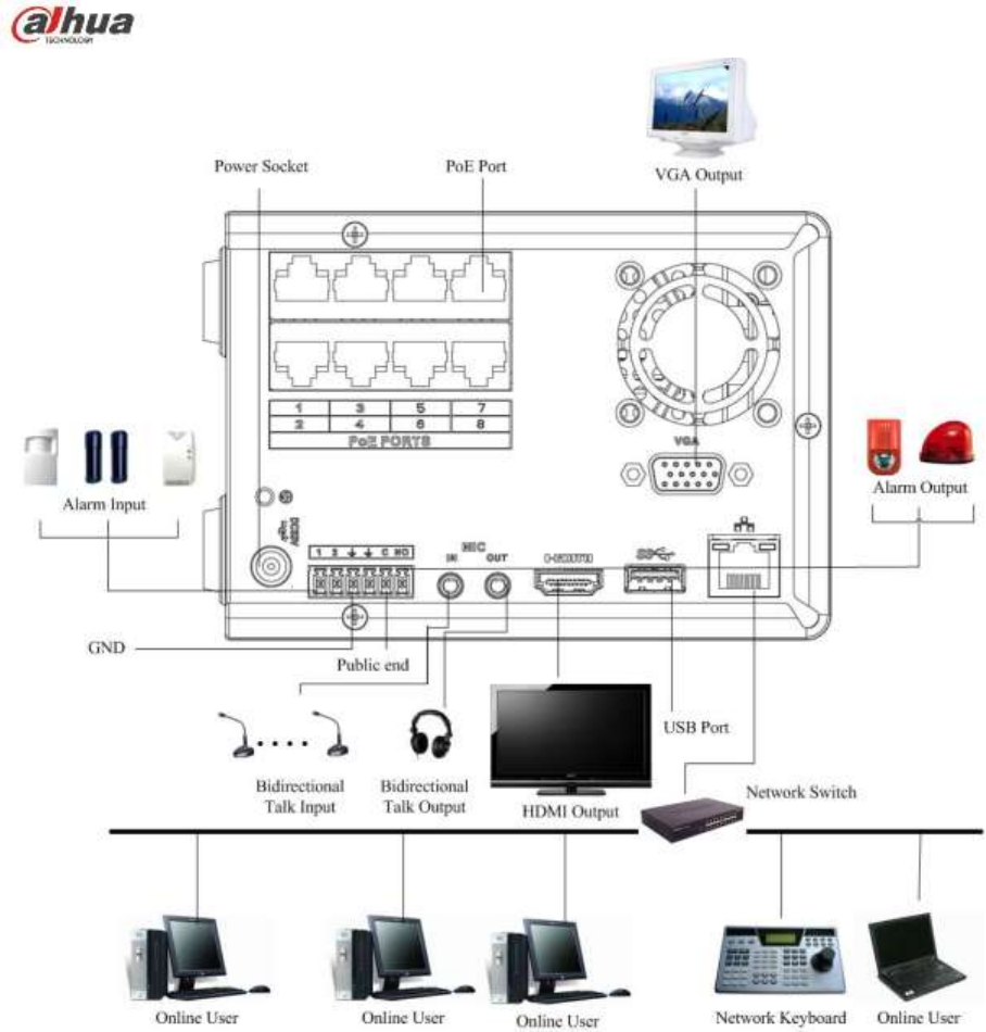
142
Figure 3-24

143
4 Local Basic Operation
4.1 Boot up and Shutdown
4.1.1 Boot up
Caution
Before the boot up, please make sure:
For device security, please connect the NVR to the power adapter first and then connect the
device to the power socket.
The rated input voltage matches the device power on-off button. Please make sure the power
wire connection is OK. Then click the power on-off button.
Always use the stable current, if necessary UPS is a best alternative measure.
Please follow the steps listed below to boot up the device.
Connect the device to the monitor and then connect a mouse.
Connect power cable.
Click the power button at the front or rear panel and then boot up the device. After device booted up,
the system is in multiple-channel display mode by default.
4.1.2 Shutdown
Note
When you see corresponding dialogue box ―System is shutting down…‖ Do not click power on-off
button directly.
Do not unplug the power cable or click power on-off button to shutdown device directly when device
is running (especially when it is recording.)
There are three ways for you to log out.
a) Main menu (RECOMMENDED)
From Main Menu->Shutdown, select shutdown from dropdown list.
Click OK button, you can see device shuts down.
b) From power on-off button on the front panel or remote control.
Press the power on-off button on the NVR front panel or remote control for more than 3 seconds to
shutdown the device.
c) From power on-off button on the rear panel.
4.2 Change/Reset Password
4.2.1 Change Password
For your own safety, please change your administrator default password after your first login.
After system booted up, you can see the following interface if it is your first login or you have restored
default setup. See Figure 4-1. Please input old password and then input new password twice to confirm
the change.
The default administrator user name is admin and the password is admin.
You can set security questions here to reset the password in case you forgot. System supports
customized setup. Please note you need to set two security questions at the same time. When you
reset the password, you need to answer these two security questions too.
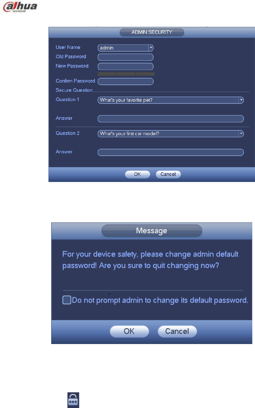
144
For reset information, please refer to chapter 4.2.2.
Figure 4-1
Click Cancel button, system pops up the following interface for you to confirm. See Figure 4-2.
Check the box here, system will not pop up the change password interface the next time.
Figure 4-2
4.2.2 Reset Password
Once you forgot password, you can answer the security questions you set in chapter 4.2.1 to reset the
password.
In login interface, click . See Figure 4-3.
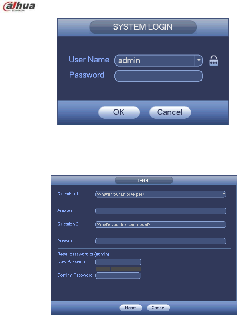
145
Figure 4-3
System pops up the following dialogue box, please answer the security questions and then input the new
password twice. See Figure 4-4.
.
Figure 4-4
4.3 Startup Wizard
After device successfully booted up, it goes to startup wizard.
Click Cancel/Next button, you can see system goes to login interface.
Tips
Check the box Startup button here, system goes to startup wizard again when it boots up the next time.
Cancel the Startup button, system goes to the login interface directly when it boots up the next time.
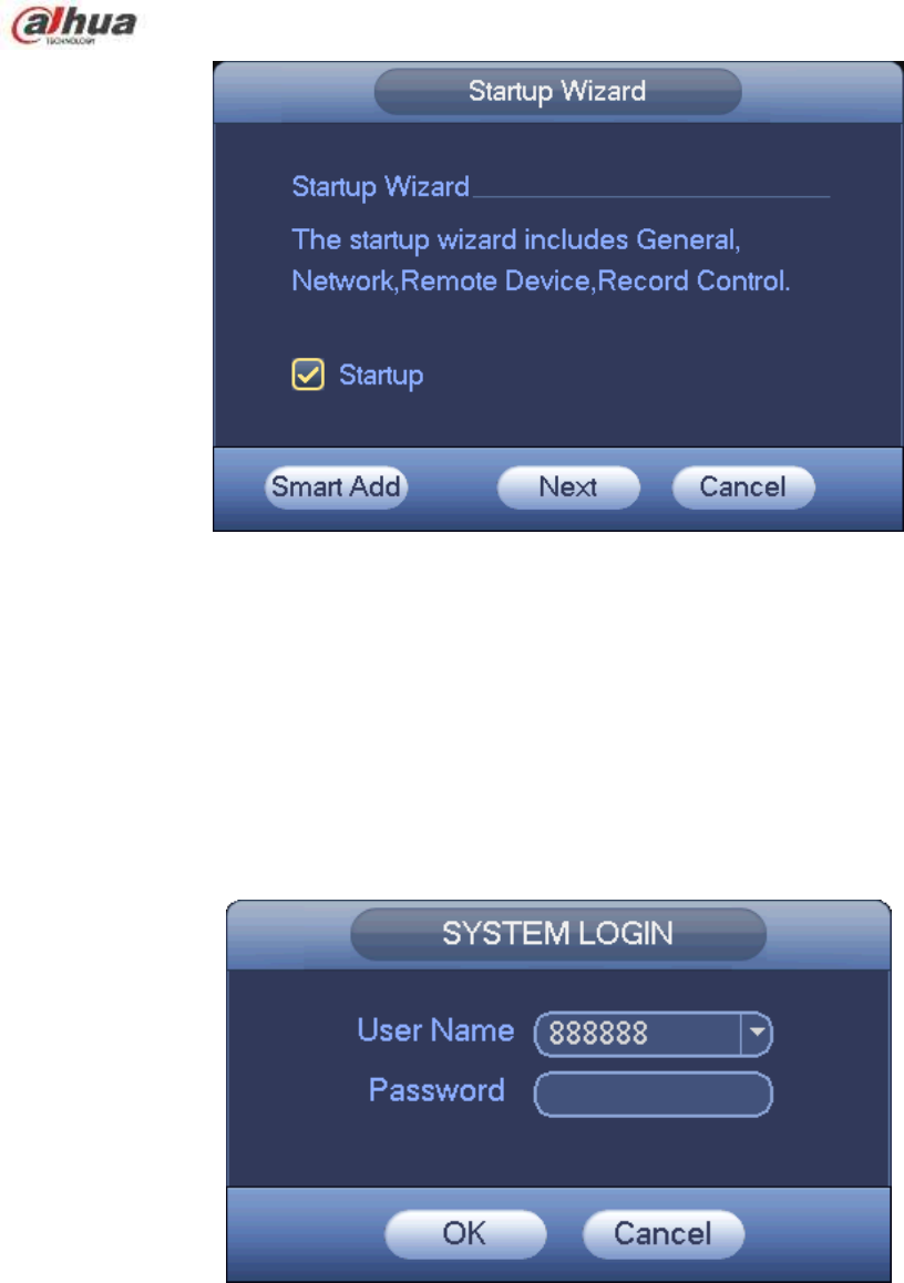
146
Figure 4-5
Click Smart add, Cancel button or Next button, system goes to login interface. See Figure 4-6.
System consists of three accounts:
Username: admin. Password: admin. (administrator, local and network)
Username: 888888. Password: 888888. (administrator, local only)
Username: default. Password: default (hidden user). Hidden user ―default‖ is for system interior use
only and can not be deleted. When there is no login user, hidden user ―default‖ automatically login.
You can set some rights such as monitor for this user so that you can view some channel view
without login.
Figure 4-6
Note:
For security reason, please modify password after you first login.
Within 30 minutes, three times login failure will result in system alarm and five times login failure will result
in account lock!
For detailed smart add information, please refer to chapter 4.5.
Click OK button, you can go to General interface. See Figure 4-7.
For detailed information, please refer to chapter 4.16.1.
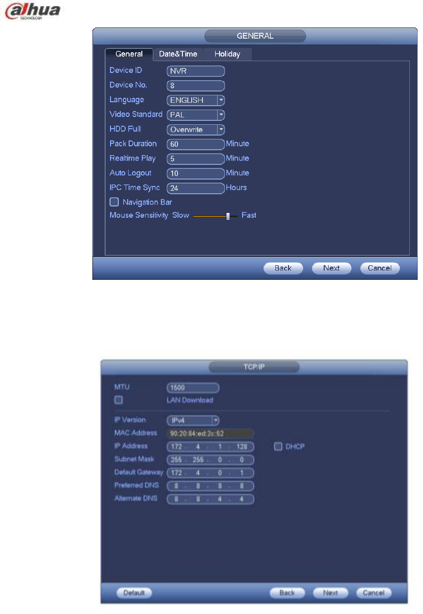
147
Figure 4-7
Click Next button, you can go to network interface. See Figure 4-8.
For detailed information, please refer to chapter 4.14.
Figure 4-8
Click Next button, you can set P2P function. Scan the QR code, download the App to the cellphone, you
can use the smart phone to add the device. See Figure 4-9.
For detailed information, please refer to chapter 4.14.1.16.
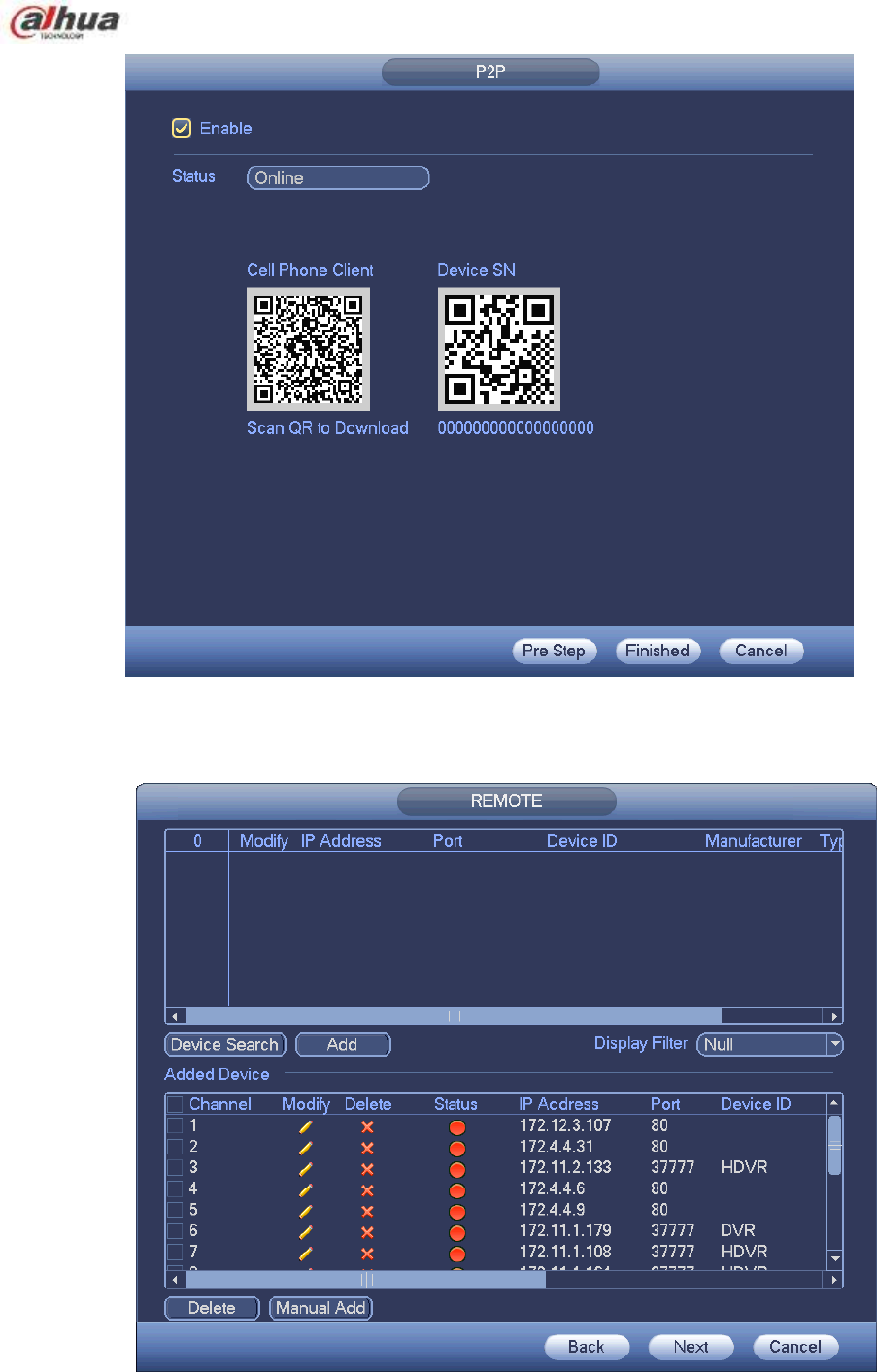
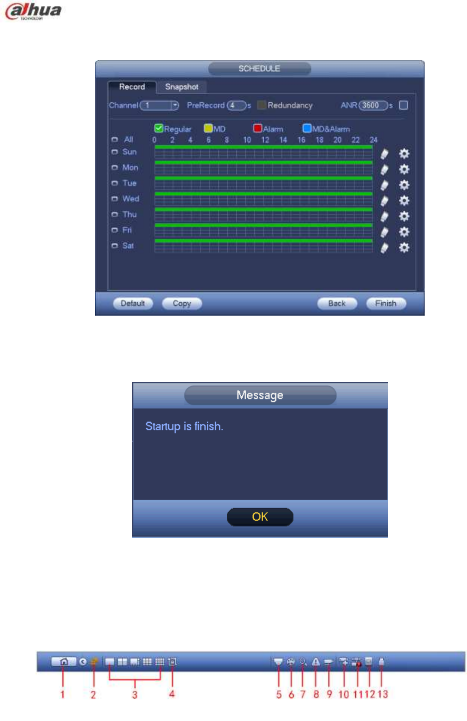
149
Click Next button, you can go to Schedule interface. See Figure 4-11.
For detailed information, please refer to chapter 4.10.2.
Figure 4-11
Click Finish button, system pops up a dialogue box. Click the OK button, the startup wizard is complete.
See Figure 4-12.
Figure 4-12
4.4 Navigation Bar
You need to go to the Main menu->Setting->System->General to enable navigation bar function;
otherwise you can not see the following interface.
The navigation bar is shown as below. See Figure 4-13.
Figure 4-13

150
4.4.1 Main Menu
Click button to go to the main menu interface.
4.4.2 Dual-screen operation
Important
This function is for some series only.
Click to select screen 2, you can view an interface shown as below. See Figure 4-14. It is a
navigation bar for screen 2.
Figure 4-14
Click any screen split mode; HDMI2 screen can display corresponding screens. Now you can control two
screens. See Figure 4-15.
Figure 4-15
Note
Screen 2 function is null if tour is in process. Please disable tour function first,
Right now, the screen 2 operation can only be realized on the navigation bard. The operations on the
right-click menu are for screen 1 only.
4.4.3 Output Screen
Select corresponding window-split mode and output channels.
4.4.4 Tour
Click button to enable tour, the icon becomes , you can see the tour is in process.
4.4.5 PTZ
Click , system goes to the PTZ control interface. Please refer to chapter 4.9.2.
4.4.6 Color
Click button , system goes to the color interface. Please refer to chapter 4.7.4.1.
Please make sure system is in one-channel mode.
4.4.7 Search
Click button , system goes to search interface. Please refer to chapter 4.11.2
4.4.8 Alarm Status
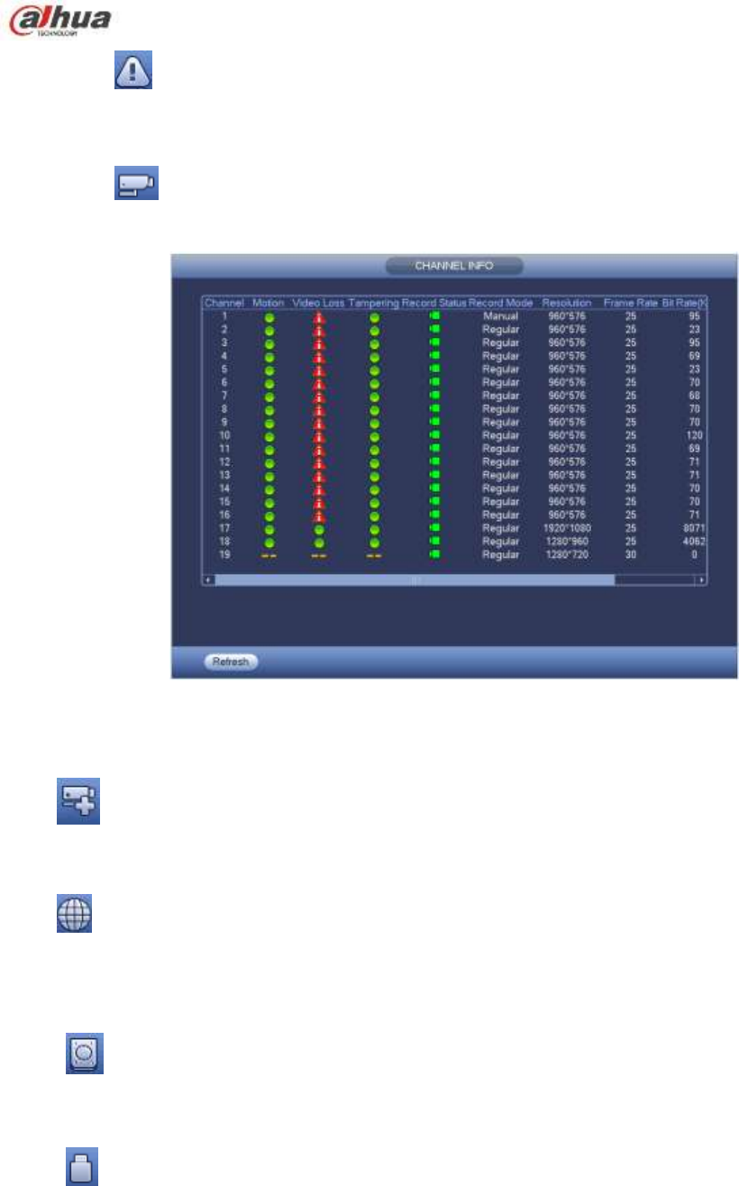
151
Click button , system goes to alarm status interface. It is to view device status and channel status.
Please refer to chapter 4.17.1.4.
4.4.9 Channel Info
Click button , system goes to the channel information setup interface. It is to view information of the
corresponding channel. See Figure 4-16.
Figure 4-16
4.4.10 Registration
Click , system goes to the registration interface. Please refer to chapter 4.5.
4.4.11 Network
Click , system goes to the network interface. It is to set network IP address, default gateway and etc.
Please refer to chapter 4.14.
4.4.12 HDD Manager
Click , system goes to the HDD manager interface. It is to view and manage HDD information.
Please refer to chapter 4.15.1.
4.4.13 USB Manager
Click , system goes to the USB Manager interface. It is to view USB information, backup and update.
Please refer to chapter 4.12.1 file backup, chapter 4.12.3 backup log, chapter4.12.2 import/export, and
chapter 4.17.5 upgrade for detailed information.
4.5 Smart Add
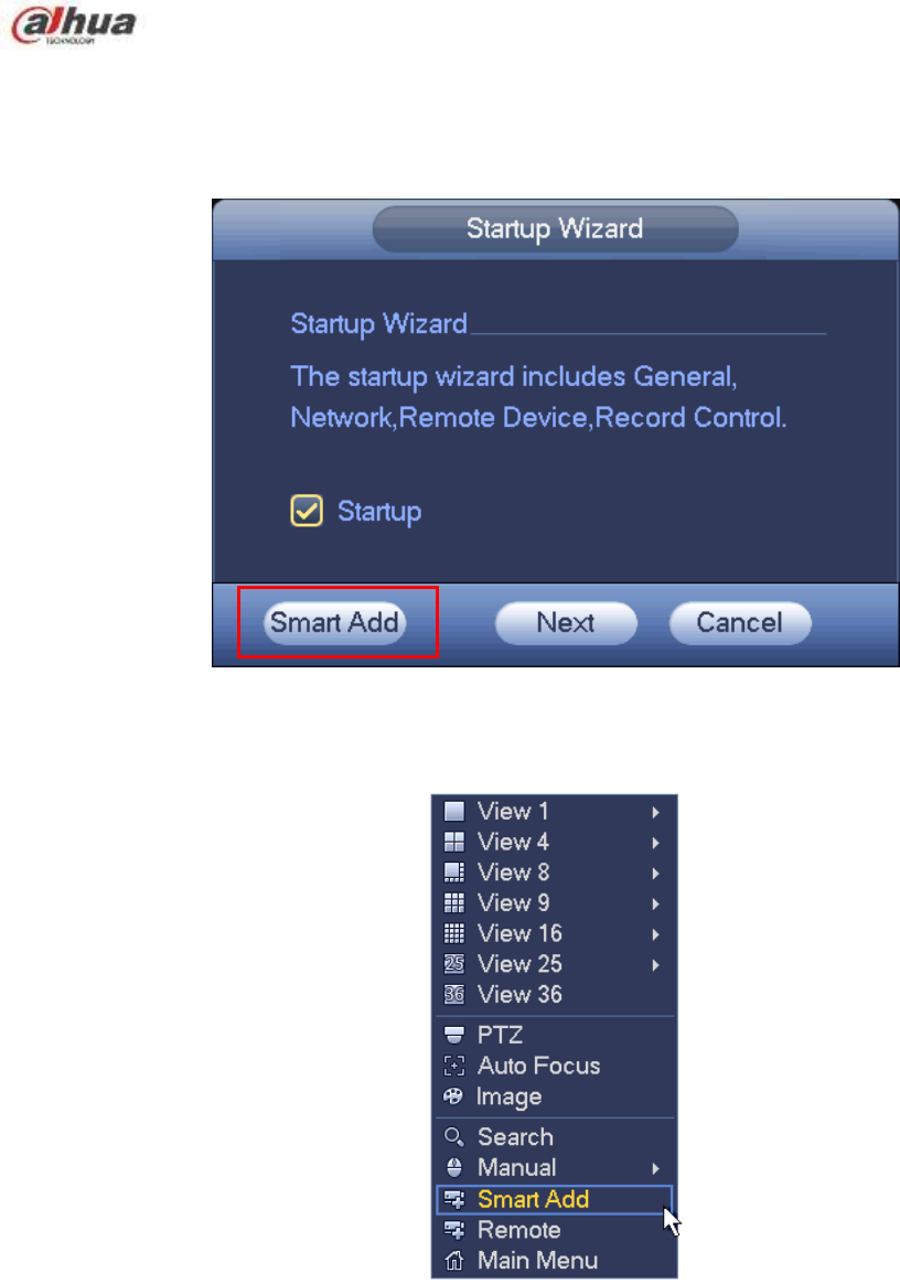
152
When the network camera(s) and the NVR are in the same router or switch, you can use smart add
function to add all network cameras to the NVR at the same time.
There are two ways for you to go to the smart add interface.
From the startup wizard, click Smart add button. See Figure 4-17.
Figure 4-17
On the preview interface, right click mouse and then select Smart add. See Figure 4-18.
Figure 4-18
Now you can go to the smart add interface. See Figure 4-19.
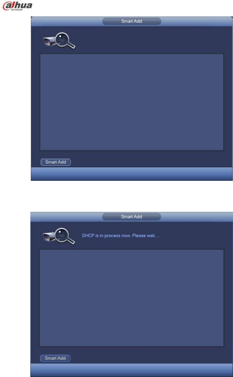
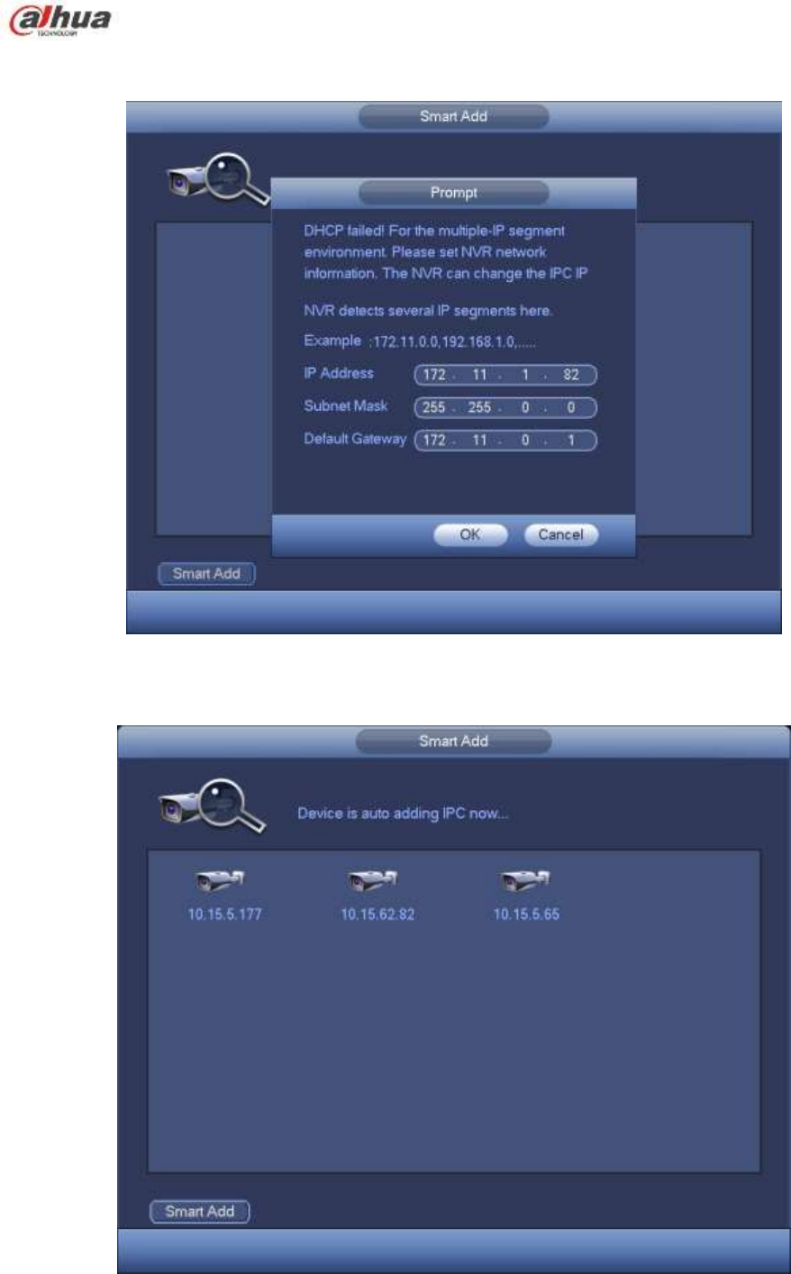

155
You can see the following dialog box after system successfully added network cameras. See Figure 4-23.
Figure 4-23
4.6 Camera
4.6.1 Registration
From Main menu->Setting->Camera->Registration, you can see the following interface. See Figure 4-24.
Device search: Click the button; you can search all network cameras in the same network segment.
Channel: It is the device channel number. If you have not added the network camera, the channel
number is shown as .
Status: Red circle ( ) means current channel has no video, green circle ( ) means current
channel has video.
IP address: It is to display network camera IP address.
Type: There are two connection types. You can use the network to connect to the camera or use the
WIFI. The means current network camera connection mode is general; the means current
network camera mode is hotspot.
Add/Delete: Click to delete the device, click to add the device to the NVR.
Manual Add: Click Manual Add button, you can set the corresponding network camera information
and then select the channel you want to add. The interface is similar to Figure 4-25.
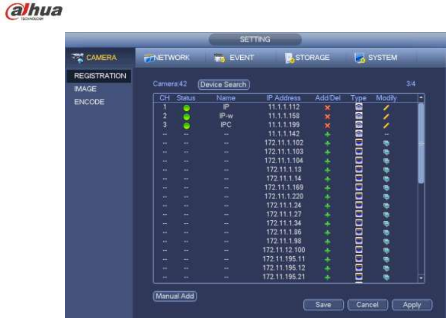
156
Figure 4-24
Modify: Click Modify button, you can see the following interface. See Figure 4-25.
Name: Change current channel name.
Protocol: Select protocol from the dropdown list.
IP Address: Input IP address here.
TCP port: Input TCP port value.
User name/Password: Input user name and password. The default user name is admin and the
default password is admin.
Decoder butter: There are three options: realtime/fluent/default. Please select from the dropdown list.
Channel: Current channel number.
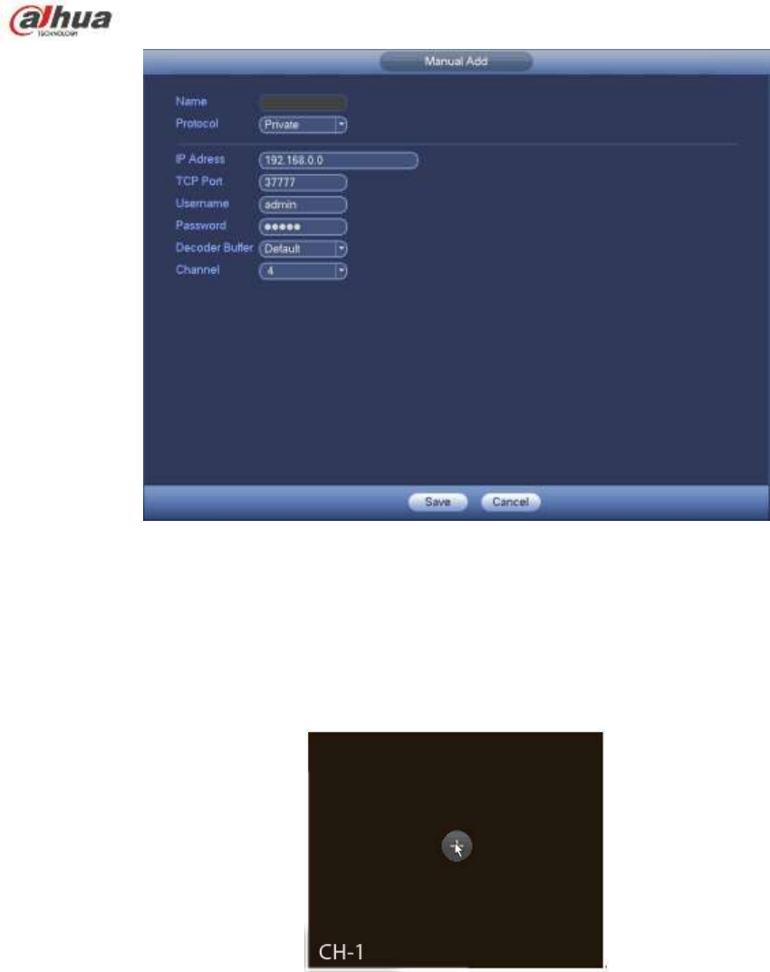
157
Figure 4-25
4.6.2 Short-Cut Menu
In the preview interface, for the channel of no IPC connection, you can click the icon ―+‖ in the centre of
the interface to quickly go to the registration interface (Figure 4-24.). See Figure 4-26.
Figure 4-26
4.6.3 Image
From main menu->setting->camera->image, you can see the image interface is shown as below. See
Figure 4-27.
Channel: Select a channel from the dropdown list.
Saturation: It is to adjust monitor window saturation. The value ranges from 0 to 100. The default
value is 50. The larger the number, the strong the color is. This value has no effect on the general
brightness of the whole video. The video color may become too strong if the value is too high. For
the grey part of the video, the distortion may occur if the white balance is not accurate. Please note
the video may not be attractive if the value is too low. The recommended value ranges from 40 to 60.

158
Brightness: It is to adjust monitor window bright. The value ranges from 0 to 100. The default value is
50. The larger the number is, the bright the video is. When you input the value here, the bright
section and the dark section of the video will be adjusted accordingly. You can use this function
when the whole video is too dark or too bright. Please note the video may become hazy if the value
is too high. The recommended value ranges from 40 to 60.
Contrast: It is to adjust monitor window contrast. The value ranges from 0 to 100. The default value
is 50. The larger the number is, the higher the contrast is. You can use this function when the whole
video bright is OK but the contrast is not proper. Please note the video may become hazy if the value
is too low. If this value is too high, the dark section may lack brightness while the bright section may
over exposure .The recommended value ranges from 40 to 60.
Auto Iris: It is for the device of the auto lens. You can check the box before ON to enable this
function. The auto iris may change if the light becomes different. When you disable this function, the
iris is at the max. System does not add the auto iris function in the exposure control. This function is
on by default.
Mirror: It is to switch video up and bottom limit. This function is disabled by default.
Flip: It is to switch video left and right limit. This function is disabled by default.
BLC: It includes several options: BLC/WDR/HLC/OFF.
BLC: The device auto exposures according to the environments situation so that the darkest area of
the video is cleared
WDR: For the WDR scene, this function can lower the high bright section and enhance the
brightness of the low bright section. So that you can view these two sections clearly at the same time.
The value ranges from 1 to 100. When you switch the camera from no-WDR mode to the WDR mode,
system may lose several seconds record video.
HLC: After you enabled HLC function, the device can lower the brightness of the brightest section
according to the HLC control level. It can reduce the area of the halo and lower the brightness of the
whole video.
OFF: It is to disable the BLC function. Please note this function is disabled by default.
Profile: It is to set the white balance mode. It has effect on the general hue of the video. This function
is on by default. You can select the different scene mode such as auto, sunny, cloudy, home, office,
night, disable and etc to adjust the video to the best quality.
Auto: The auto white balance is on. System can auto compensate the color temperature to make
sure the vide color is proper.
Sunny: The threshold of the white balance is in the sunny mode.
Night: The threshold of the white balance is in the night mode.
Customized: You can set the gain of the red/blue channel. The value reneges from 0 to 100.
Day/night. It is to set device color and the B/W mode switch. The default setup is auto.
Color: Device outputs the color video.
Auto: Device auto select to output the color or the B/W video according to the device feature (The
general bright of the video or there is IR light or not.)
B/W: The device outputs the black and white video.
Sensor: It is to set when there is peripheral connected IR light.
Please note some non-IR series product support sensor input function.
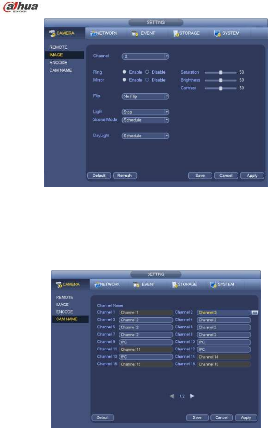
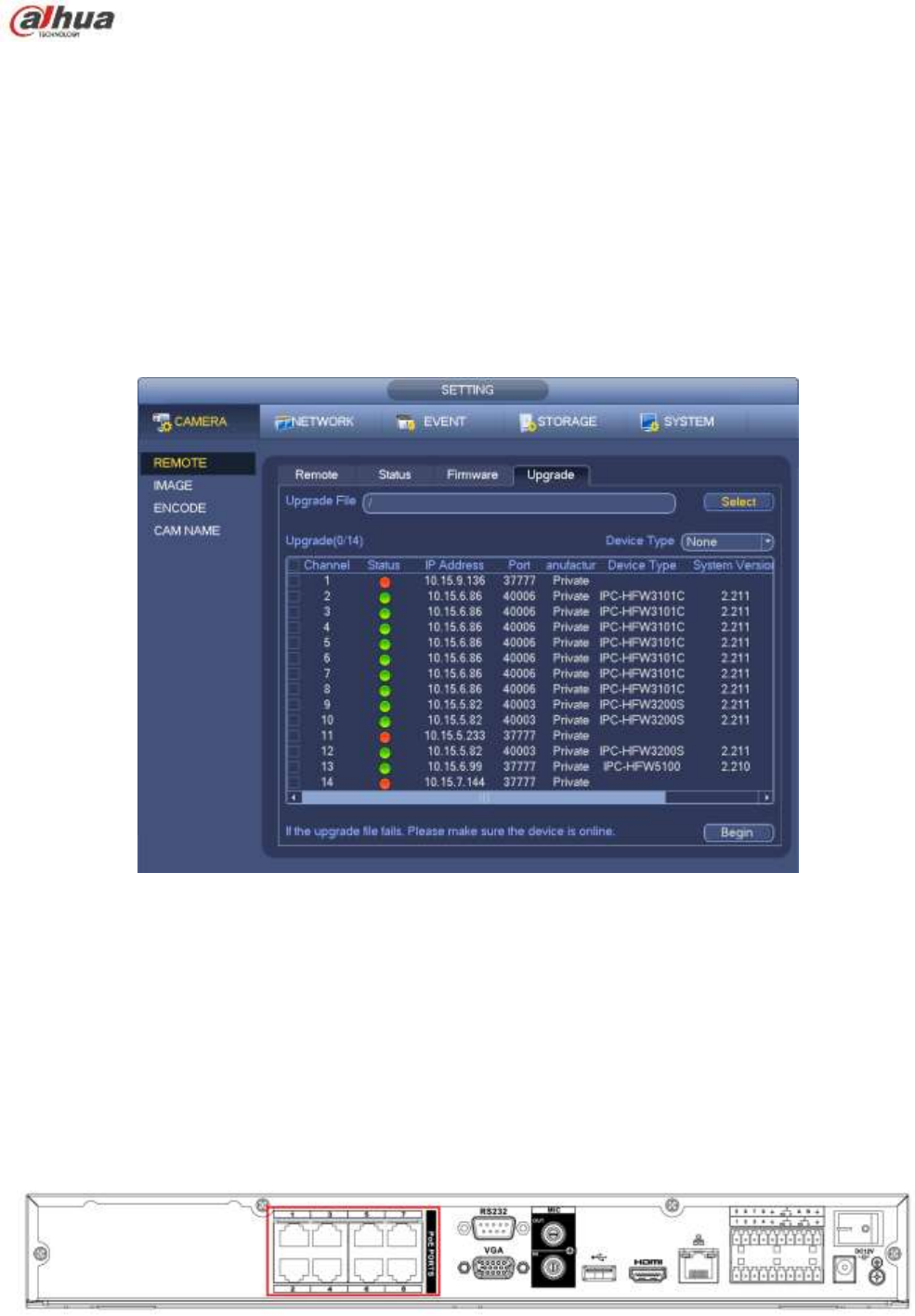
160
4.6.5 Upgrade
Note
Right now, the NVR can upgrade the IPC via the USB device or WEB. You can upgrade 8 network
cameras of the same model (or the NVR supported) at the same time.
It is to update the network camera.
From main menu->setting->camera->remote, the interface is shown as below. See Figure 4-29.
Click Browse button and then select the upgrade file. Then select a channel (or you can select device
type filter to select several devices at the same time.)
Click Begin button to upgrade. You can see the corresponding dialogue once the upgrade is finish.
Figure 4-29
4.6.6 UPNP
Important
Do not connect the switch to the PoE port, otherwise the connection may fail!
Please connect the IPC to the PoE port of the device rear panel (Figure 4-30), system can auto connect
to the network camera. Please note the following figure is for reference only.
Figure 4-30
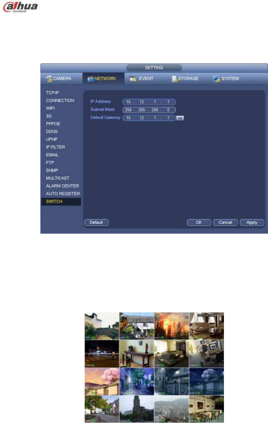
161
4.6.7 Built-in Switch Setup
The built-in switch function is for product of PoE port.
From Main menu->Setting->Network->Switch, you can set switch IP address, subnet mask, gateway and
etc. See Figure 4-31.
Figure 4-31
4.7 Preview
After device booted up, the system is in multiple-channel display mode. See Figure 4-32.Please note the
displayed window amount may vary. The following figure is for reference only. Please refer to chapter 1.3
Specifications for the window-amount your product supported.
Figure 4-32
4.7.1 Preview
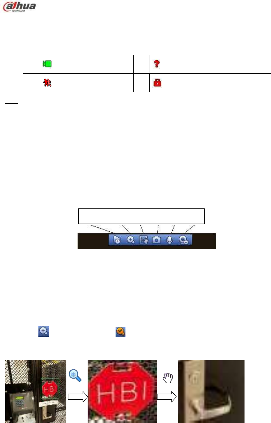
162
If you want to change system date and time, you can refer to general settings (Main
Menu->Setting->System->General). If you want to modify the channel name, please refer to the
display settings (Main Menu->Camera->CAM name)
Please refer to the following sheet for detailed information.
Tips
Preview drag: If you want to change position of channel 1 and channel 2 when you are
previewing, you can left click mouse in the channel 1 and then drag to channel 2, release mouse
you can switch channel 1 and channel 2 positions.
Use mouse middle button to control window split: You can use mouse middle button to switch
window split amount.
4.7.2 Preview control interface
Move you mouse to the top centre of the video of current channel, you can see system pops up the
preview control interface. See Figure 4-33. If your mouse stays in this area for more than 6 seconds
and has no operation, the control bar automatically hides.
Figure 4-33 Digital Channel
1) Realtime playback
It is to playback the previous 5-60 minutes record of current channel.
Please go to the Main menu->Setting->->System->General to set real-time playback time.
System may pop up a dialogue box if there is no such record in current channel.
2) Digital zoom
It is to zoom in specified zone of current channel. It supports zoom in function of multiple-channel.
Click button , the button is shown as .
There are two ways for you to zoom in.
Drag the mouse to select a zone, you can view an interface show as Figure 4-34.
Figure 4-34
1 Recording status 3 Video loss
2 Motion detection 4 Camera lock
1 2 3 4 6 7
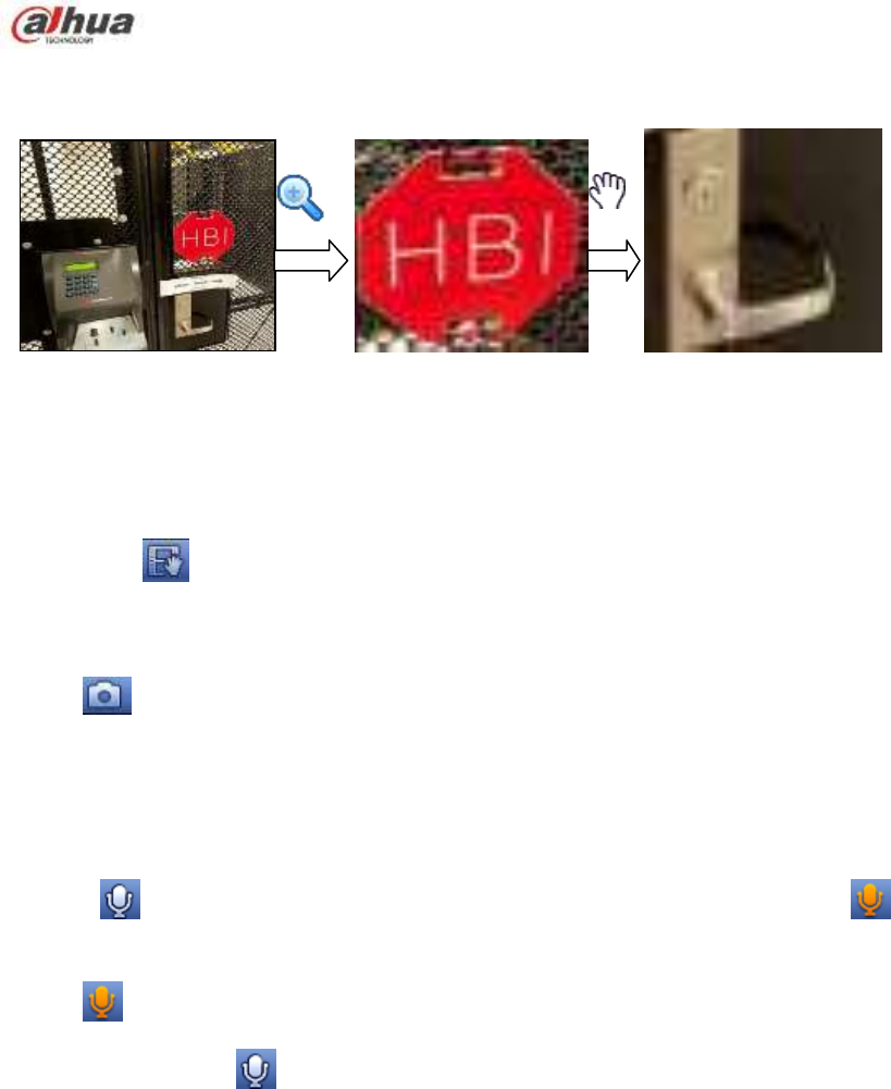
163
Put the middle button at the centre of the zone you want to zoom in, and move the mouse, you
can view an interface shown as in Figure 4-35.
Figure 4-35
Right click mouse to cancel zoom and go back to the original interface.
3) Manual record function
It is to backup the video of current channel to the USB device. System can not backup the video of
multiple-channel at the same time.
Click button , system begins recording. Click it again, system stops recoridng. You can find the record
file on the flash disk.
4) Manual Snapshot
Click to snapshot 1-5 times. The snapshot file is saved on the USB device or HDD. You can go to
the Search interface (chapter 4.11) to view.
5) Bidirectional talk
If the connected front-end device supports bidirectional talk function, you can click this button. Click
button to start bidirectional talk function the icon now is shown as . Now the rest
bidirectional talk buttons of digital channel becomes null too.
Click again, you can cancel bidirectional talk and the bidirectional talk buttons of other digital
channels become as .
6) Registration
Shortcut menu. Click it to go to the registration interface to add/delete remote device or view its
corresponding information. Please refer to chapter4.6.2 for detailed information.
4.7.3 Right Click Menu
After you logged in the device, right click mouse, you can see the short cut menu. Please see Figure
4-36.
Window split mode: You can select window amount and then select channels.
PTZ: Click it to go to PTZ interface.
Fish eye(optional): It is to realize fish eye operation.
Auto focus: It is to set auto focus function. Please make sure the connected network camera
supports this function.
Color setting: Set video corresponding information.
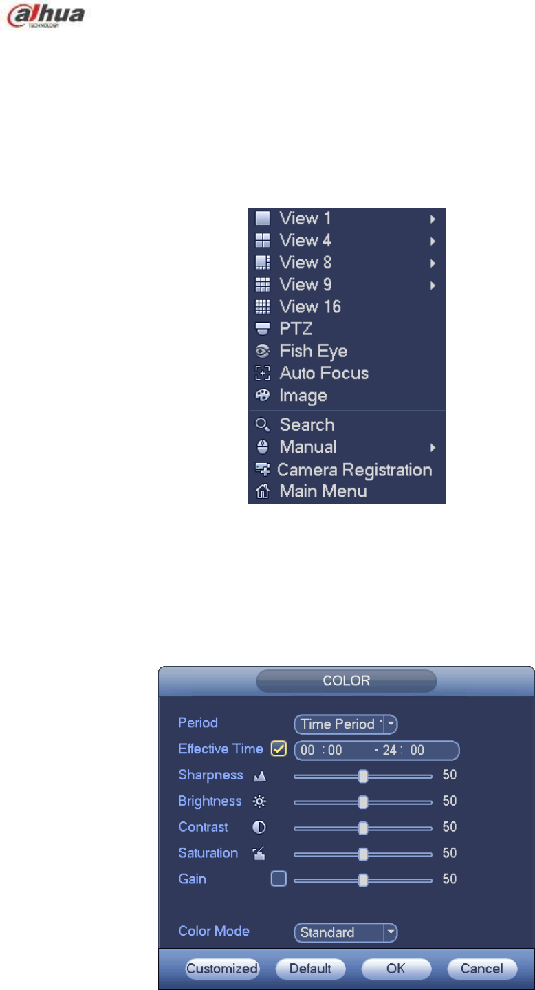
164
Search: Click it to go to Search interface to search and playback a record file.
Record control: Enable/disable record channel.
Alarm output: It is to set alarm output mode.
Camera registration: Search and add a remote device.
Alarm output: Generate alarm output signal manually.
Main menu: Go to system main menu interface.
Tips:
Right click mouse to go back to the previous interface.
Figure 4-36
4.7.4 Preview Display Effect Setup
4.7.4.1 Video Color
Here you can set hue, brightness, contrast, saturation, gain, white level, color mode and etc. See
Figure 4-37.
Figure 4-37

165
Please refer to the following sheet for detailed information.
Item
Note
Period
There are two periods in one day. You can set different
sharpness, brightness, and contrast setup for different periods.
Effective Time
Check the box here to enable this function and then set period
time.
Sharpness
The value here is to adjust the edge of the video. The value
ranges from 0 to 100. The larger the value is, the clear the edge
is and vice versa. Please note there is noise if the value here is
too high. The default value is 50 and the recommended value
ranges from 40 to 60.
Brightness
It is to adjust monitor window bright. The value ranges from 0 to
100. The default value is 50.
The larger the number, the bright the video is. When you input
the value here, the bright section and the dark section of the
video will be adjusted accordingly. You can use this function
when the whole video is too dark or too bright. Please note the
video may become hazy if the value is too high. The
recommended value ranges from 40 to 60.
Contrast
It is to adjust monitor window contrast. The value ranges from 0
to 100. The default value is 50.
The larger the number, the higher the contrast is. You can use
this function when the whole video bright is OK but the contrast
is not proper. Please note the video may become hazy if the
value is too low. If this value is too high, the dark section may
lack brightness while the bright section may over exposure .The
recommended value ranges from 40 to 60.
Saturation
It is to adjust monitor window saturation. The value ranges from
0 to 100. The default value is 50.
The larger the number, the strong the color is. This value has
no effect on the general brightness of the whole video. The
video color may become too strong if the value is too high. For
the grey part of the video, the distortion may occur if the white
balance is not accurate. Please note the video may not be
attractive if the value is too low. The recommended value
ranges from 40 to 60.
Gain
The gain adjust is to set the gain value. The default value may
vary due to different device models. The smaller the value, the
low the noise. But the brightness is also too low in the dark
environments. It can enhance the video brightness if the value
is high. But the video noise may become too clear.
Color mode
It includes several modes such as standard, color, bright,
gentle. Select a color mode, the sharpness, brightness,
contrast and etc can automatically switch to corresponding
setup.
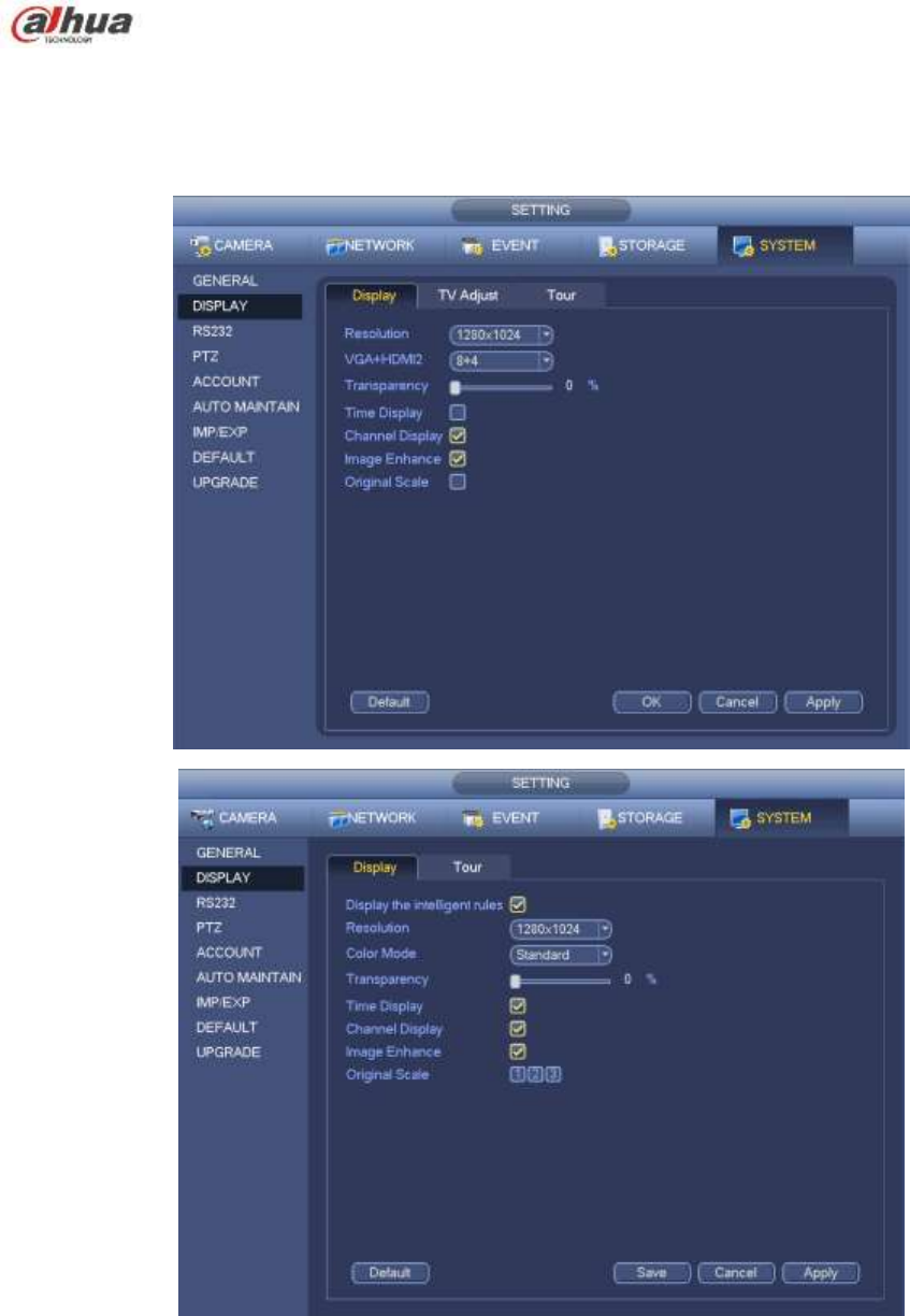
166
4.7.4.2 Display
From Main Menu->Setting->System->Display, you can go to the following interface. See Figure 4-38.
Here you can set menu and video preview effect. All you operation here does not affect the record file and
playback effect.
Figure 4-38
Now you can set corresponding information.
Display the intelligent rule(s): Check the box to enable IVS function, system can display IVS rule on
the preview interface. Please note this function is for some series only.
Resolution: There are five options: 1280×1024 (Default), 1280×720, 1920×1080, 1024×768 and
3840×2160. Please note the system needs to reboot to activate current setup. Please note
3840×2160 is for some series only.

167
VGA+HDMI2: It is for dual-screen operation. Please select from the dropdown list according to your
actual situation. Click Apply button, system needs to restart to activate new setup. For example,
32+4 means for VGA, system max supports 32-window split and for HDMI2, system max supports
4-window split. Please note this function is for some series only.
Color mode: Please select from the dropdown list. It is to set video color mode.
Transparency: Here is for you to adjust menu transparency. The higher the value is, the better
transparent the menu is.
Channel name: Here is for you to modify channel name. System max support 25-digit (The value
may vary due to different series). Please note all your modification here only applies to NVR local
end. You need to open web or client end to refresh channel name.
Time display: You can select to display time or not when system is playback.
Channel display: You can select to channel name or not when system is playback.
Image enhance: Check the box; you can optimize the margin of the preview video.
Original scale: Check the box here to select a corresponding channel; it can restore video original
scale.
Click OK button to save current setup.
4.7.4.3 TV adjust
Note
Some series product supports TV adjust function. This function is disabled by default.
From Main Menu->Setting->System->Display->TV adjust; you can go to the following interface. See
Figure 4-38. Here you can set margins and brightness.
Figure 4-39
4.7.5 Preview Tour Parameters
Set preview display mode, channel display sequence and tour setup.
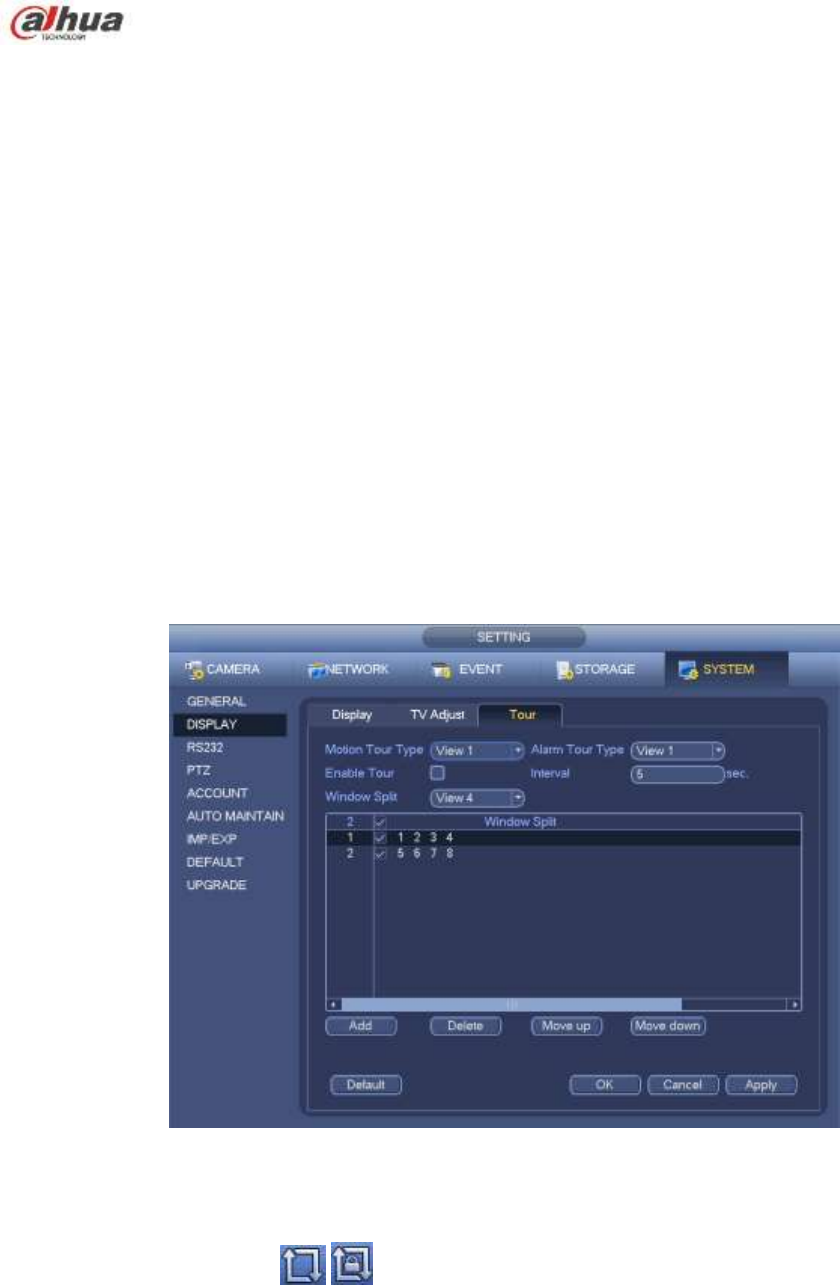
168
Set preview display mode: On the preview interface, right click mouse, you can view right-click menu.
Now you can select preview window amount and channel.
Set channel display mode: On the preview interface, if you want to change channel 1 and channel 16
position, please right click channel 1 video window and then drag to the channel 16 video window,
release button, you can change channel 1 and channel 16 position.
Tour setup: Here you can set preview window channel display mode and interval. Please follow the
steps listed below.
From Main menu->Setting->System->Display->Tour, you can see an interface shown as in Figure 4-40.
Here you can set tour parameter.
Enable tour: Check the box here to enable tour function. The general tour supports all types of
window split mode.
Interval: Input proper interval value here. The value ranges from 1-120 seconds.
Motion tour type: System support 1/8-window tour. Please note you need to go to the main
menu->Setting->Event->Video detect->Motion detect to enable tour function.
Alarm tour type: System support 1/8-window tour. Please note you need to go to the main
menu->Setting->Event->Alarm to enable tour function.
Window split: It is to set window split mode.
Figure 4-40
Tips
On the navigation bar, click / to enable/disable tour.
Click Save button to save current setup.
4.8 Fish eye (Optional)
Please note this function is for some series only.
4.8.1 Fish eye de-warp during preview interface
On the preview interface, select fish eye channel and then right click mouse, you can select fish eye. See
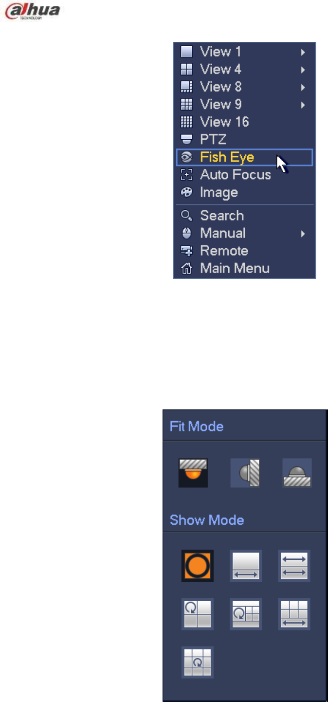
169
Figure 4-41.
Figure 4-41
Now you can see an interface shown as in Figure 4-42. You can set fish eye installation mode and display
mode.
Note:
For the non-fish eye channel, system pops up dialogue box to remind you it is not a fish eye channel
and does not support de-warp function.
If system resources are insufficient, system pops up the corresponding dialogue box too.
Figure 4-42
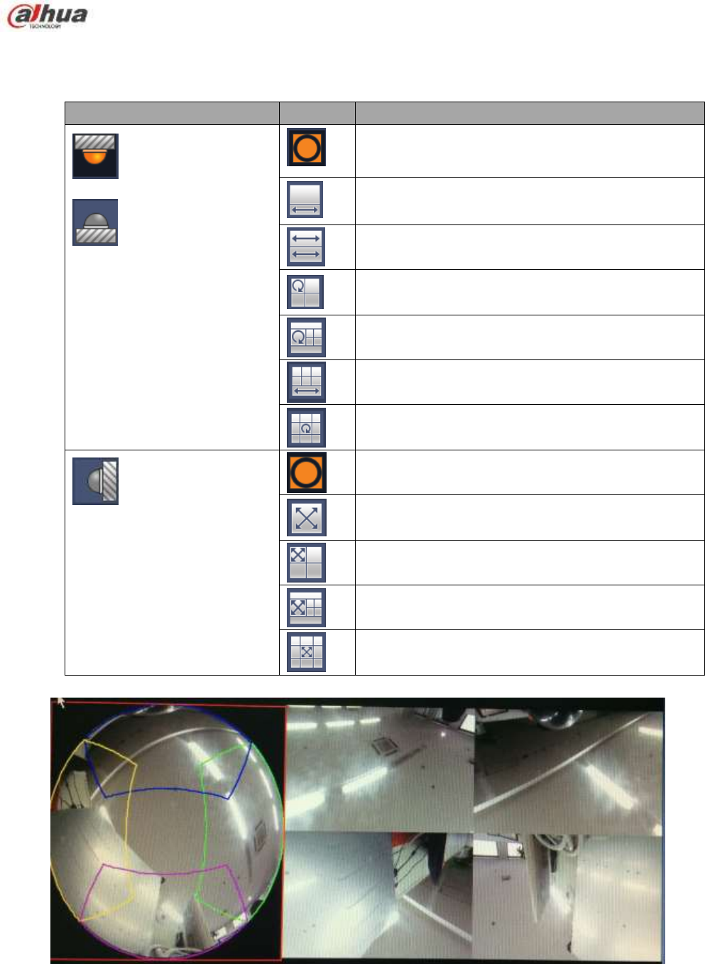
170
There are three installation modes: ceiling mount/wall mount/ground mount. The different
installations modes have different de-warp modes.
Please refer to the following sheet for detailed information.
Installation modes
Icon
Note
(Ceiling mount)
(Ground mount)
360°panorama original view
1 de-warp window+1 panorama stretching
2 panorama stretching view
1 360° panorama view+3 de-warp windows
1 360°panorama view+4 de-warp windows
4 de-warp windows+1 panorama stretching
1 360° panorama view+8 de-warp windows
(Wall mount)
360°panorama original view
Panorama stretching
1 panorama unfolding view+3 de-warp windows
1 panorama unfolding view +4 de warp windows
1 panorama unfolding view +8 de warp windows
Figure 4-43
In Figure 4-43, you can adjust the color pane on the left pane or use your mouse to change the
position of the small images on the right pane to realize fish eye de-warp.

171
4.8.2 Fish eye de-warp during playback
On the main menu, click search button.
Select 1-window playback mode and corresponding fish eye channel, click to play.
Right click the , you can go to the de-warp playback interface. For detailed information, please
refer to chapter 4.8.1.
4.9 PTZ
Note:
Before you control the PTZ, please make sure the PTZ decoder and the NVR network
connection is OK and the corresponding settings are right.
4.9.1 PTZ Settings
Cable Connection
Please follow the procedures below to go on cable connection
Connect the dome RS485 port to NVR RS485 port.
Connect dome video output cable to NVR video input port.
Connect power adapter to the dome.
In the main menu, from Setting->System->PTZ, you can see an interface is shown as in Figure 4-44.
Here you can set the following items:
Channel: Select the current camera channel.
PTZ type: There are two types: local/remote. Please select local mode if you are connect RS485
cable to connect to the Speed dome (PTZ). Please select remote mode if you are connecting to the
network PTZ camera.
Protocol: Select corresponding PTZ protocol(such as PELCOD)
Address: Default address is 1.
Baud rate: Select corresponding baud rate. Default value is 9600.
Data bit: Select corresponding data bits. Default value is 8.
Stop bit: Select corresponding stop bits. Default value is 1.
Parity: There are three options: odd/even/none. Default setup is none.
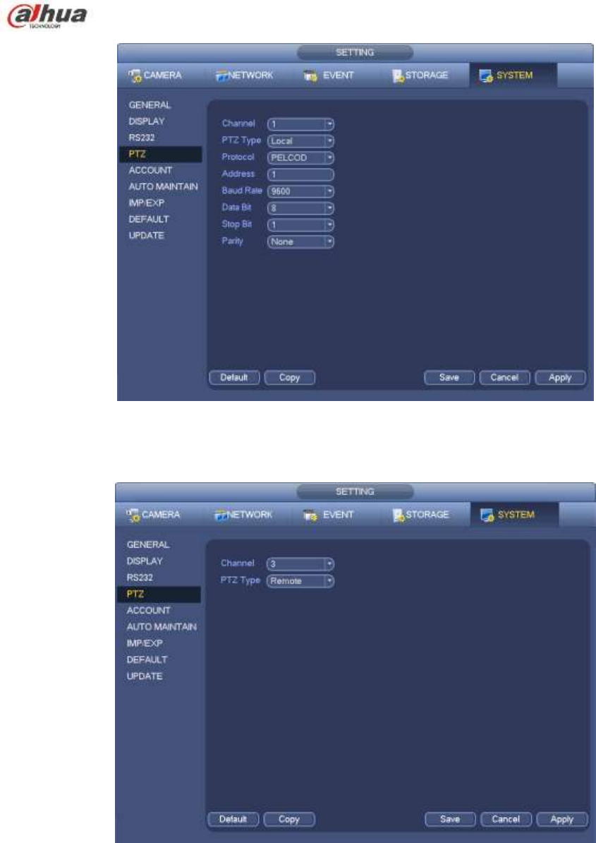
172
Figure 4-44
If you are connecting to network PTZ, the PTZ type shall be remote. See Figure 4-45.
Figure 4-45
4.9.2 PTZ Control
After completing all the setting please click save button. Right click mouse (click ―Fn‖ Button in the
front panel or click ―Fn‖ key in the remote control). The interface is shown as in Figure 4-46. Please
note you can only go to the PTZ control interface when you are in 1-window display mode.
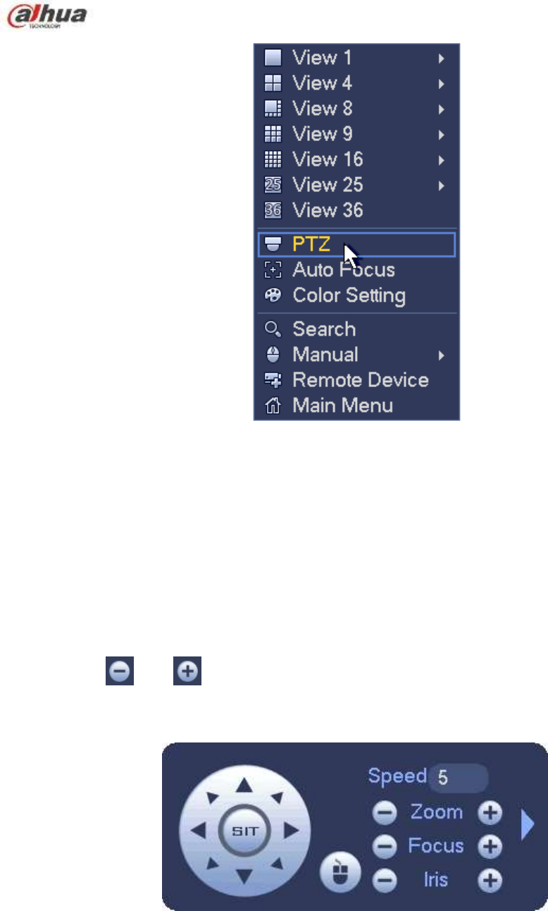
173
Figure 4-46
The PTZ setup is shown as in See Figure 4-47.
Please note the commend name is grey once device does not support this function.
The PTZ operation is only valid in one-window mode.
Here you can control PTZ direction, speed, zoom, focus, iris, preset, tour, scan, pattern aux function, light
and wiper, rotation and etc.
Speed is to control PTZ movement speed. The value ranges from 1 to 8.The speed 8 is faster than speed
1. You can use the remote control to click the small keyboard to set.
You can click and of the zoom, focus and iris to zoom in/out, definition and brightness.
The PTZ rotation supports 8 directions. If you are using direction buttons on the front panel, there are only
four directions: up/down/left/right.
Figure 4-47
In the middle of the eight direction arrows, there is a 3D intelligent positioning key. See Figure 4-48.
Please make sure your protocol supports this function and you need to use mouse to control.
Click this key, system goes back to the single screen mode. Drag the mouse in the screen to adjust
section size. The dragged zone supports 4X to 16X speeds. It can realize PTZ automatically. The smaller
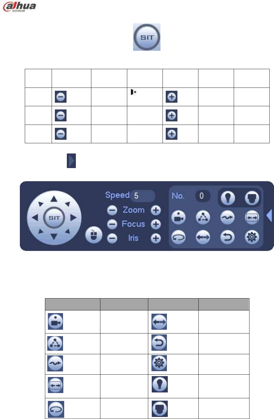
174
zone you dragged, the higher the speed.
Figure 4-48
Name
Function
key
function
Shortcut
key
Function
key
function
Shortcut
key
Zoom
Near
Far
Focus
Near
│
Far
►│
Iris
close
Open
In Figure 4-47, click to open the menu, you can set preset, tour, pattern, scan and etc. See
Figure 4-49.
Figure 4-49
Please refer to the following sheet for detailed information.
Please note the above interface may vary due to different protocols. The button is grey and can not
be selected once the current function is null.
Right click mouse or click the ESC button at the front panel to go back to the Figure 4-47.
Icon
Function
Icon
Function
Preset
Flip
Tour
Reset
Pattern
Aux
Scan
Aux on-off
button
Rotate
Go to menu
4.9.2.1 PTZ Function Setup
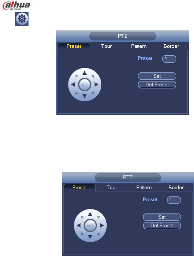
175
Click , you can go to the following interface to set preset, tour, pattern, and scan. See Figure 4-50.
Figure 4-50
Preset Setup
In Figure 4-50, click preset button and use eight direction arrows to adjust camera to the proper position.
The interface is shown as in Figure 4-51.
Click Set button and then input preset number.
Click Set button to save current preset.
Figure 4-51
Tour Setup
In Figure 4-50, click tour button.
Input tour value and preset No. Click Add preset button to add current preset to the tour. See Figure 4-52.
Tips
Repeat the above steps to add more presets to the tour. Click Del preset button to remove it from the tour.
Please note some protocols do not support delete preset function.
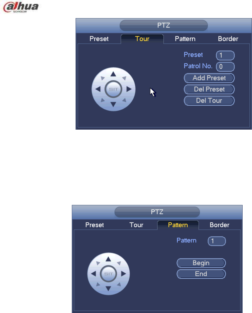
176
Figure 4-52
Pattern Setup
In Figure 4-50, click Pattern button and input pattern number.
Click Begin button to start direction operation. Or you can go back to Figure 4-47 to operate
zoom/focus/iris/direction operation.
In Figure 4-50, click End button.
Figure 4-53
Scan Setup
In Figure 4-50, click Scan button.
Use direction buttons to set camera left limit and then click Left button.
Use direction buttons to set camera right limit and then click Right button. Now the scan setup process is
complete.
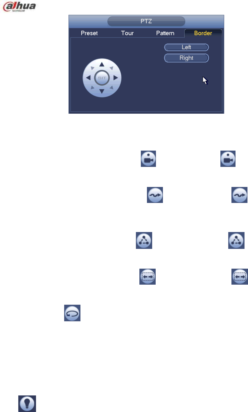
177
Figure 4-54
4.9.2.2 Call PTZ Function
Call Preset
In Figure 4-49, input preset value and then click to call a preset. Click again to stop call.
Call Pattern
In Figure 4-49, input pattern value and then click to call a pattern. Click again to stop
call.
Call Tour
In Figure 4-49, input tour value and then click to call a tour. Click again to stop call.
Call Scan
In Figure 4-49, input Scan value and then click to call a tour. Click again to stop call.
Rotate
In Figure 4-49, click to enable the camera to rotate.
System supports preset, tour, pattern, scan, rotate, light and etc function.
Note:
Preset, tour and pattern all need the value to be the control parameters. You can define it as you
require.
You need to refer to your camera user’s manual for Aux definition. In some cases, it can be used for
special process.
Aux
Click , system goes to the following interface. The options here are defined by the protocol. The aux
number is corresponding to the aux on-off button of the decoder. See Figure 4-55.

178
Figure 4-55
4.10 Record and Snapshot
The record/snapshot priority is: Alarm->Motion detect->Schedule.
4.10.1 Encode
4.10.1.1 Encode
Encode setting is to set IPC encode mode, resolution, bit stream type and etc
From Main menu->Setting->System->Encode, you can see the following interface. See Figure 4-56.
Channel: Select the channel you want.
Type: Please select from the dropdown list. There are three options: regular/motion detect/alarm.
You can set the various encode parameters for different record types.
Compression: System supports H.264, MPEG4, MJPEG and etc.
Resolution: The mainstream resolution type is IPC’s encoding config. Generally there is
D1/720P/1080P. For NVR42-4K, NVR42-8P-4K series product, the main stream supports 2048×
1536(3M),1920×1080(1080P), 1280×1024(S×GA), 1280×960(1.3M),1280×720(720P),704
×576(D1)and the sub stream supports 704×576(D1),352×288(CIF).
Frame rate: It ranges from 1f/s to 25f/s in NTSC mode and 1f/s to 30f/s in PAL mode.
Bit rate type: System supports two types: CBR and VBR. In VBR mode, you can set video quality.
Quality: There are six levels ranging from 1 to 6. The sixth level has the highest image quality.
Video/audio: You can enable or disable the video/audio. Please note, once you enable audio
function for one channel, system may enable audio function of the rest channels by default.
Copy:After you complete the setup, you can click Copy button to copy current setup to other
channel(s). You can see an interface is shown as in Figure 4-59. You can see current channel
number is grey. Please check the number to select the channel or you can check the box ALL.
Please click the OK button in Figure 4-59 and Figure 4-57 respectively to complete the setup. Please
note, once you check the All box, you set same encode setup for all channels. Audio/video enable
box, overlay button and the copy button is shield.
Please highlight icon to select the corresponding function.
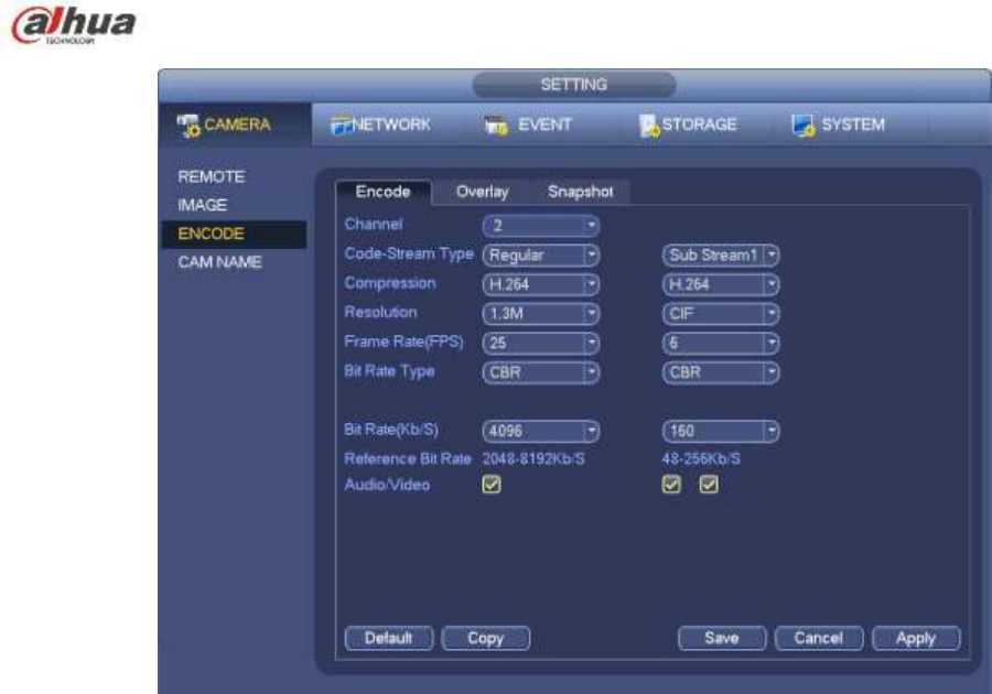
179
Figure 4-56
4.10.1.2 Overlay
Click overlay button, you can see an interface is shown in Figure 4-57.
Cover area: Here is for you to cover area section. You can drag you mouse to set proper section size.
In one channel video, system max supports 4 zones in one channel. You can set with Fn button or
direction buttons.
Preview/monitor: The cover area has two types. Preview and Monitor. Preview means the privacy
mask zone can not be viewed by user when system is in preview status. Monitor means the privacy
mask zone can not be view by the user when system is in monitor status.
Time display: You can select system displays time or not when you playback. Please click set button
and then drag the title to the corresponding position in the screen.
Channel display: You can select system displays channel number or not when you playback. Please
click set button and then drag the title to the corresponding position in the screen.
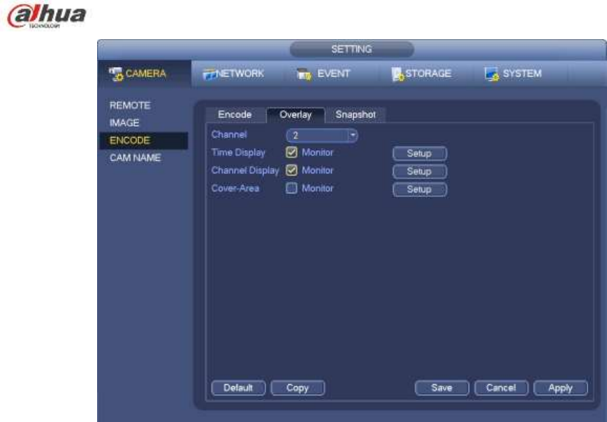
180
Figure 4-57
4.10.1.3 Snapshot
Here you can set snapshot mode, picture size, quality and frequency. See Figure 4-58.
Snapshot mode: There are two modes: regular and trigger. If you set regular mode, you need to set
snapshot frequency. If you set trigger snapshot, you need to set snapshot activation operation.
Image size: Here you can set snapshot picture size.
Image quality: Here you can set snapshot quality. The value ranges from 1 to 6.
Interval: It is for you to set timing (schedule) snapshot interval.
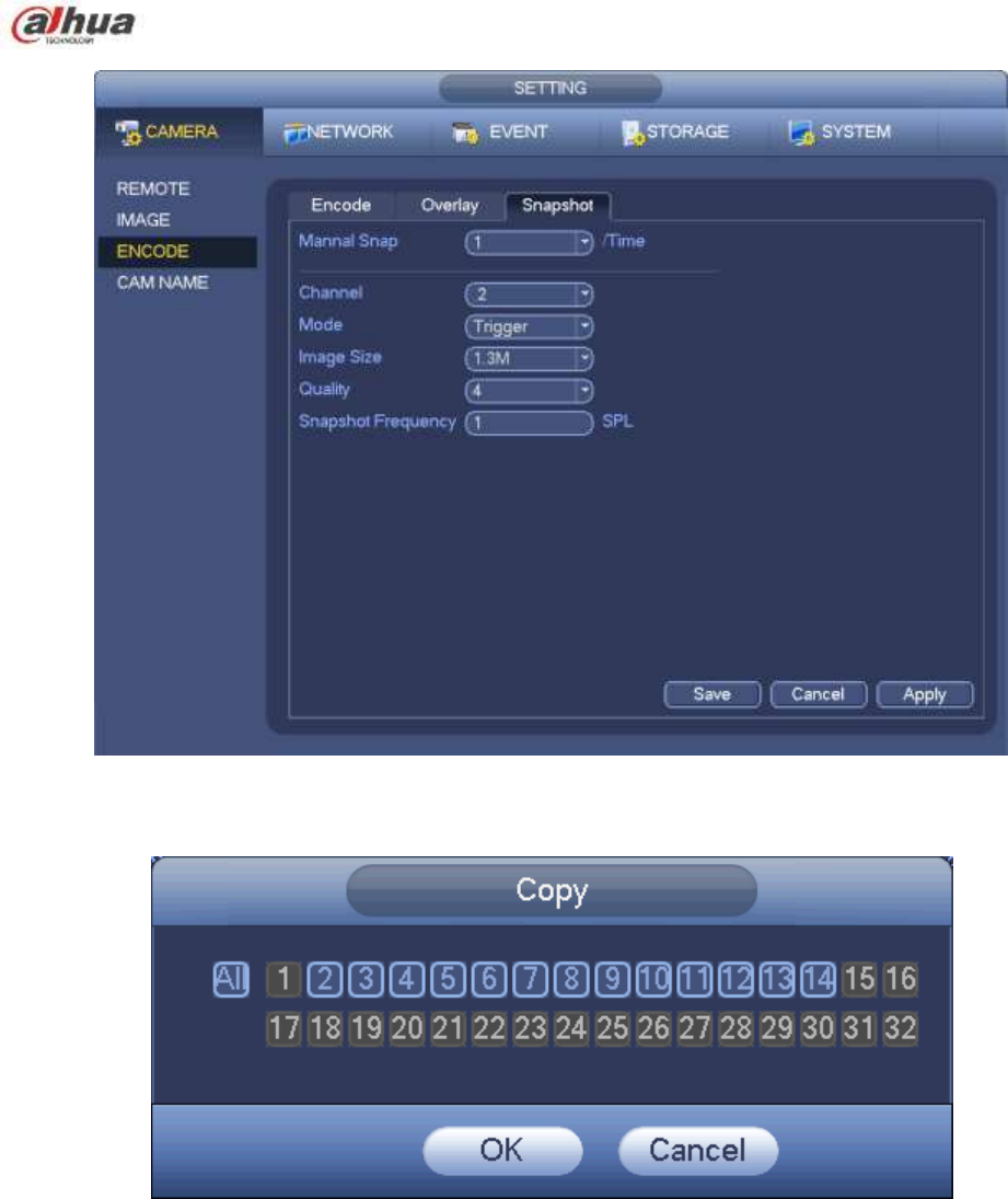
181
Figure 4-58
Figure 4-59
4.10.2 Schedule
The record type priority is: Alarm>Motion detect>Regular.
4.10.2.1 Schedule Record
Set record time, record plan and etc. Please note system is in 24-hour record by default after its first
boot up.
In the main menu, from Main menu->Setting->Storage->Schedule, you can go to schedule menu.
See Figure 4-63. There are total six periods.

182
Channel: Please select the channel number first. You can select ―all‖ if you want to set for the whole
channels.
: Sync connection icon. Select icon of several dates, all checked items can be edited or
together. Now the icon is shown as .
: Click it to delete a record type from one period.
Record Type: Please check the box to select corresponding record type. There are four types:
Regular/MD (motion detect)/Alarm/MD&Alarm.
Week day: There are eight options: ranges from Saturday to Sunday and all.
Holiday: It is to set holiday setup. Please note you need to go to the General interface (Main
Menu->Setting->System->General) to add holiday first. Otherwise you can not see this item.
Pre-record: System can pre-record the video before the event occurs into the file. The value ranges
from 1 to 30 seconds depending on the bit stream.
Redundancy: System supports redundancy backup function. It allows you backup recorded file in
two disks. You can highlight Redundancy button to activate this function. Please note, before enable
this function, please set at least one HDD as redundant. (Main menu->Setting->Storage->HDD
Manager). Please note this function is null if there is only one HDD.
ANR: It is to save video to the SD card of the network camera in case the network connection fails.
The value ranges from 0s~43200s. After the network connection resumed, the system can get the
video from the SD card and there is no risk of record loss.
Period setup: Click button after one date or a holiday, you can see an interface shown as in
Figure 4-64.There are four record types: regular, motion detection (MD), Alarm, MD & alarm.
Please following the steps listed below to draw the period manually.
a) Select a channel you want to set. See Figure 4-60.
Figure 4-60
b) Set record type. See Figure 4-61.
Figure 4-61
c) Please draw manually to set record period. There are six periods in one day. See Figure 4-62.
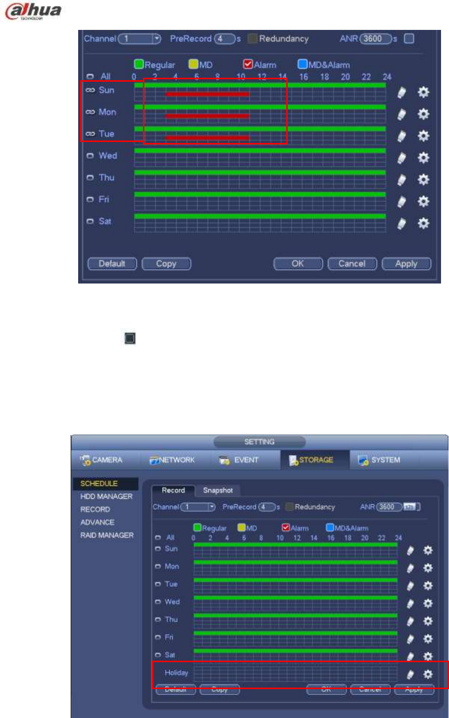
183
Figure 4-62
Please check the box to select the corresponding function. After completing all the setups please
click save button, system goes back to the previous menu.
There are color bars for your reference. Green color stands for regular recording, yellow color stands
for motion detection and red color stands for alarm recording. The white means the MD and alarm
record is valid. Once you have set to record when the MD and alarm occurs, system will not record
neither motion detect occurs nor the alarm occurs.
Figure 4-63
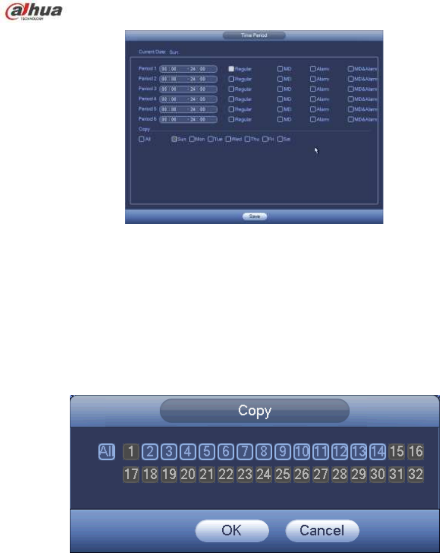
184
Figure 4-64
Quick Setup
Copy function allows you to copy one channel setup to another. After setting in channel 1, click Copy
button, you can go to interface Figure 4-65. You can see current channel name is grey such as channel 1.
Now you can select the channel you want to paste such as channel 5/6/7. If you want to save current
setup of channel 1 to all channels, you can click the first box ―ALL‖. Click the OK button to save current
copy setup. Click the OK button in the Encode interface, the copy function succeeded.
Please note, if you select ALL in Figure 4-65, the record setup of all channels are the same and the Copy
button becomes hidden.
Figure 4-65
Click OK button to save current setup.
4.10.2.2 Schedule Snapshot
From Main menu->Setting->Storage->Record or on the preview interface, right click mouse and then
select record item, you can see Figure 4-66.
Select snapshot channel and enable snapshot function. Click Save button.
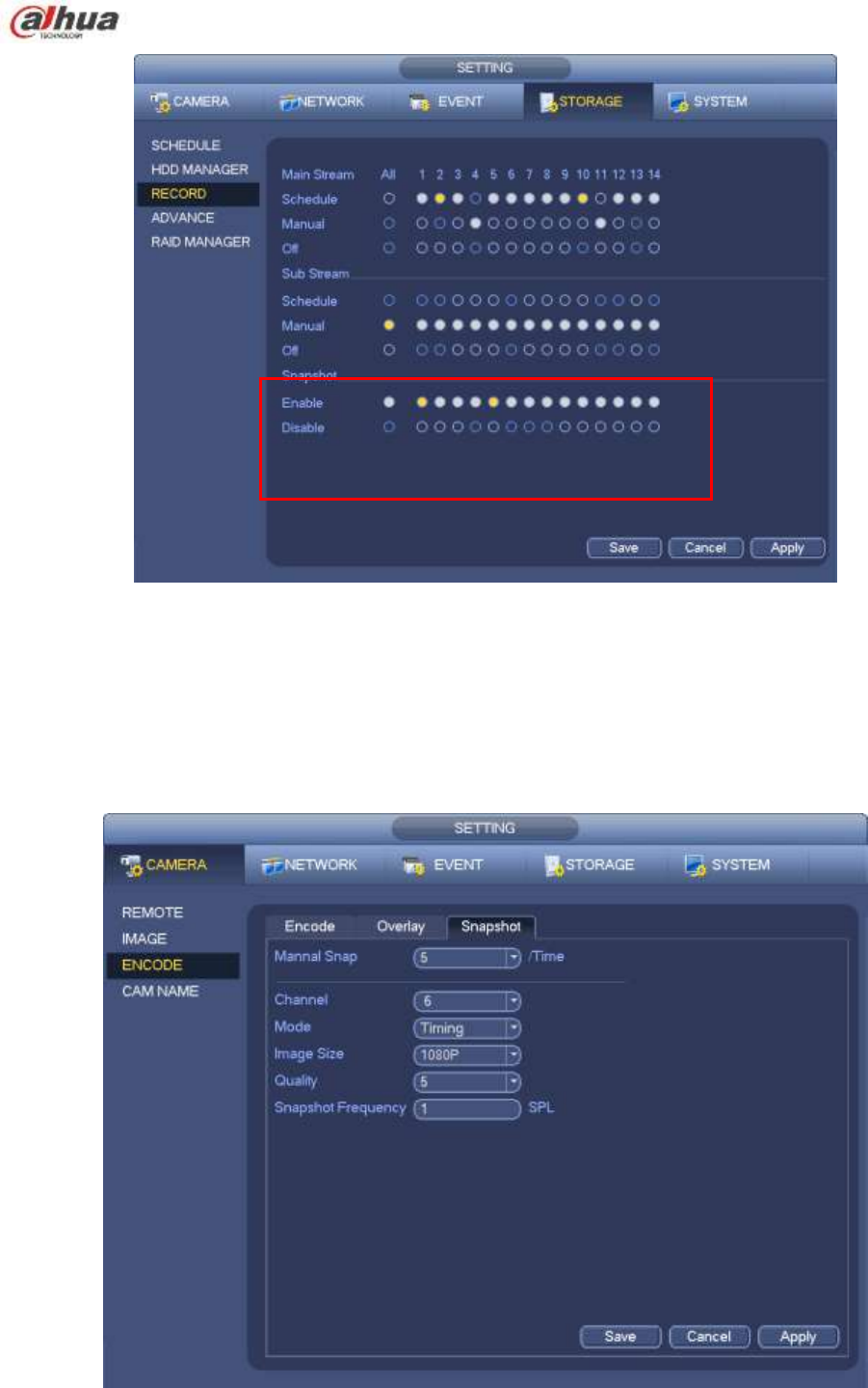
185
Figure 4-66
From Main menu->Setting->Camera->Encode->Snapshot, you can go to snapshot interface. See Figure
4-67.
Select the snapshot channel from the dropdown list and then select snapshot mode as Timing (Schedule)
from the dropdown list and then set picture size, quality and snapshot frequency.
Figure 4-67
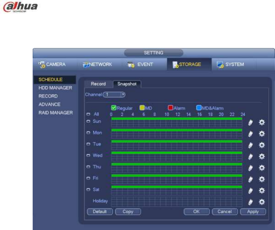
186
In the main menu, from Main menu->Setting->Storage->Schedule, you can go to schedule menu.
See Figure 4-63. Here you can set snapshot period. There are total six periods in one day. Please refer
to chapter 4.10.2.1 for detailed setup information. The setup steps are general the same.
Figure 4-68
Note
Please note the trigger snapshot has the higher priority than regular snapshot. If you have enabled
these two types at the same time, system can activate the trigger snapshot when an alarm occurs,
and otherwise system just operates the regular snapshot.
Only the trigger snapshot supports this function. The regular snapshot function can not send out
picture via the email. But you can upload the picture to a FTP.
4.10.3 Motion detect record/snapshot
4.10.3.1 Motion detect record
a) From Main menu->Setting->Event->Detect, you can go to the following interface. See Figure
4-69.