Zhejiang Dahua Vision Technology DHNVR41WSX Network Video Recorder User Manual 2
Zhejiang Dahua Vision Technology Co., Ltd Network Video Recorder Users Manual 2
Contents
- 1. Users Manual-1
- 2. Users Manual-2
Users Manual-2
187
Figure 4-69
b) Select motion detect from the event type dropdown list. Select a channel from the dropdown list
and then check the enable button to enable motion detect function.
c) Click Region Select button to set motion detect zone. There are 396(PAL)/330(NTSC) small
zones. The green zone is current cursor position. Grey zone is the motion detection zone. Black
zone is the disarmed zone. You can click Fn button to switch between the arm mode and disarm
mode. In arm mode, you can click the direction buttons to move the green rectangle to set the
motion detection zone. After you completed the setup, please click ENTER button to exit current
setup. Do remember click save button to save current setup. If you click ESC button to exit the
region setup interface system will not save your zone setup.
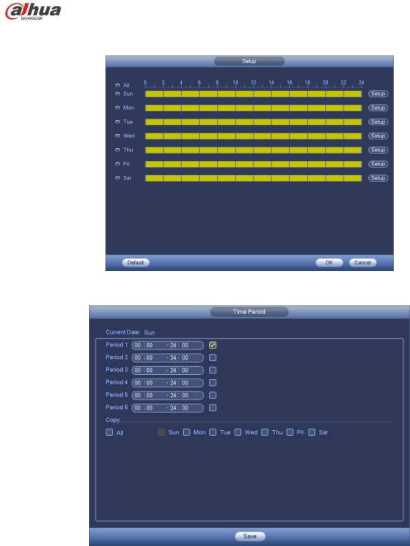
d) Period: Click set button, you can see an interface is shown as in Figure 4-92. Here you can set
motion detect period. System only enables motion detect operation in the specified periods. It is
not for video loss or the tampering. There are two ways for you to set periods. Please note
system only supports 6 periods in one day.
In Figure 4-92, Select icon of several dates, all checked items can be edited together. Now
the icon is shown as . Click to delete a record type from one period.
In Figure 4-92. Click button after one date or a holiday, you can see an interface shown as in
Figure 4-93. There are four record types: regular, motion detection (MD), Alarm, MD & alarm.
e) Set sensitivity. Please note the sixth level has the highest sensitivity.
f) Click Save button to complete motion detect setup.
g) From Main menu->Setting->Storage->-Schedule. See Figure 4-63
h) Set motion detect record channel, period and the record type shall be motion detect (MD).
Please refer to chapter 4.10.2.
188
i) Click Copy button to copy current setup to other channel(s).
j) Click OK button to complete motion detect record setup.
Figure 4-70
Figure 4-71
4.10.3.2 Motion Detect Snapshot
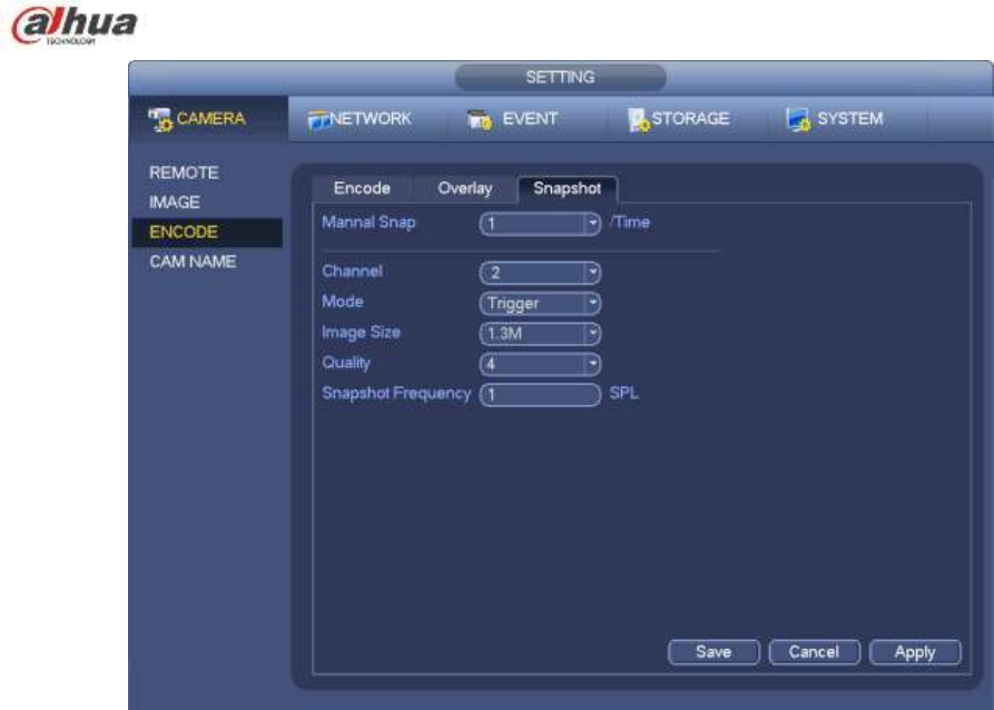
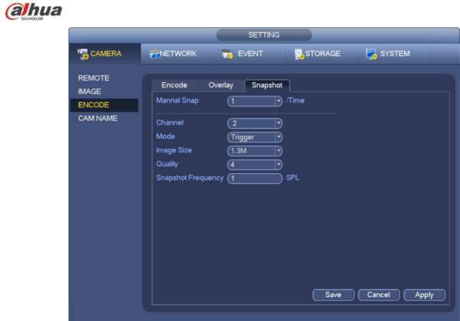
a) From Main menu->Setting->Camera->Encode->Snapshot, you can go to snapshot interface.
See Figure 4-72.
b) In Figure 4-72, select trigger snapshot from the dropdown list and then set picture size, quality
and snapshot frequency. Click OK button to save current setup.
c) From Main menu->Setting->Event->Detect, here you can select motion detect type, motion
detect channel and then check the enable box. Please refer to chapter 4.10.3.1.
d) Click OK button to complete motion detect setup.
189
Figure 4-72
4.10.4 Alarm Record/Snapshot
4.10.4.1 Alarm Record
a) Before you set alarm setup information, please go to chapter 2.3 to connect alarm input and
alarm output cable (such as light, siren and etc).
b) The record priority is: Alarm>Motion detect>Regular.
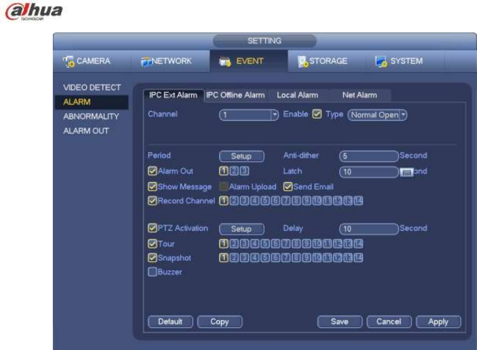
In the main menu, from Setting->Event-> Alarm, you can see alarm setup interface. See Figure 4-73.
Alarm in: Here is for you to select channel number.
Event type: There are four types. Local input/network input/IPC external/IPC offline alarm.
Local input alarm: The alarm signal system detects from the alarm input port.
Network input alarm: It is the alarm signal from the network.
IPC external alarm: It is the on-off alarm signal from the front-end device and can activate the
local NVR.
IPC offline alarm: Once you select this item, system can generate an alarm when the front-end
IPC disconnects with the local NVR. The alarm can activate record, PTZ, snapshot and etc. The
alarm can last until the IPC and the NVR connection resumes.
Enable: Please you need to highlight this button to enable current function.
Type: normal open or normal close.
c) Click Save button to complete alarm setup interface.
190
Figure 4-73
d) From Mani menu->Setting->Storage->Schedule, you can go to Figure 4-63.
e) Select alarm channel, period and the record type shall be alarm. Please refer to chapter 4.10.2.
f) Click Copy button to copy current setup to other channel(s).
g) Click OK button to save alarm record information.
4.10.4.2 Alarm Snapshot
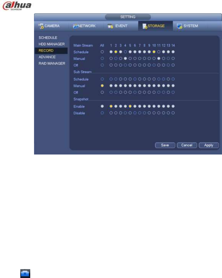
a) Please refer to Step a) to step c) of chapter 4.10.3.2 to enable timing snapshot.
b) From Main menu->Setting->Storage->schedule, you can go to Figure 4-74 to enable snapshot
function.
c) From Main menu->Setting->Event->Alarm, you can go to Figure 4-73 to set alarm parameter
and enable snapshot function.
d) Click Save button to save alarm snapshot setup.
191
Figure 4-74
4.10.5 Manual Record/Snapshot
You need to have proper rights to implement the following operations. Please make sure the HDD
has been properly installed.
4.10.5.1 Manual Record
a) Right click mouse and select manual record or in the main menu, from
Setting->Storage->Manual Record. Manual record menu is shown as in Figure 4-75.
Tips
You can click Rec button on the front panel (if possible) to go to the Manual Record interface.
192
Figure 4-75
b) Check the box here to select manual record channel(s). You can see the corresponding
indicator light on the front panel is on.
Channel: It is to display device all channels.
Manual: It has the highest priority. Enable corresponding channel to record no matter what period
applied in the record setup. Now system is record general file.
Auto: System enables auto record function as you set in chapter 4.10.2 schedule interface
(General/Motion detect/Alarm)
Stop: Stop current channel record/Snapshot no matter what period applied in the record setup.
All: Check the All box to select all channels.
c) Click OK button to complete manual record setup.
4.10.5.2 Manual Snapshot
Click button at the preview control bar, you can snapshot 1-5 picture(s). From main
menu->Setting->Camera->Encode->Snapshot, you can set snapshot times. You can go to chapter 4.11 to
view snapshot picture.
4.10.6 Holiday Record/Snapshot
It is for you to set holiday record or snapshot plan. Please note the holiday record/snapshot setup has the
higher priority than the ordinary date record/snapshot setup.
4.10.6.1 Holiday Record
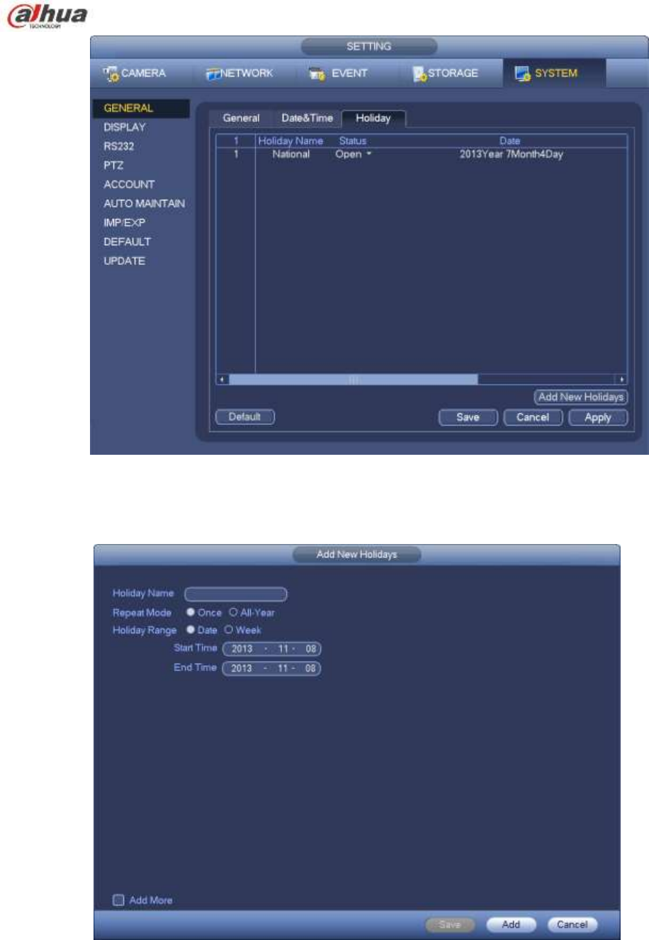
a) From Mani menu->Setting->System->General, you can go to the following interface. See Figure
4-76.
193
Figure 4-76
b) Click Add new holiday button, you can see an interface shown as in Figure 4-77. Here you can
set holiday date name, repeat mode, start time/end time and etc.
Figure 4-77
c) Click Add button to complete holiday setup. Now you can enable holiday setup and then click
Apply button.
d) From Main menu->setting->Storage->schedule, you can go to schedule interface. See Figure
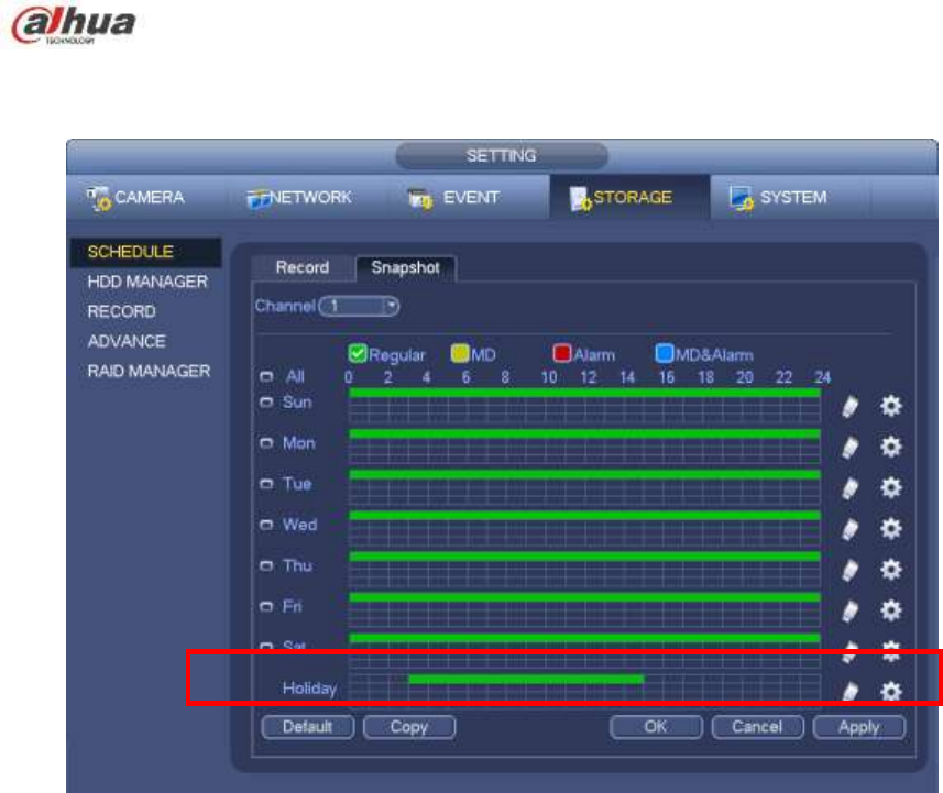
194
4-78. Now you can set period and record type of holiday time. Please refer to chapter 4.10.2.1
for detailed setup information.
Figure 4-78
e) Click OK button to set holiday record setup.
4.10.6.2 Holiday Snapshot
Set Holiday date first. Please refer to step a) to step c) of chapter 4.10.6.1.
From Main menu->Setting->Storage->Schedule, you can go to schedule interface. See Figure 4-78. Click
Holiday item to set snapshot period.
Set holiday snapshot type (Trigger/Regular). Please refer to chapter 4.10.2.2 or chapter 4.10.3.2.
4.10.7 Other Record/Snapshot
Motion detect&Alarm record or snapshot, please refer to chapter 4.10.4.
Video loss or tampering record or snapshot function, please refer to chapter 4.10.3.
4.11 Playback and Search
4.11.1 Real-time Playback
Please refer to chapter 4.7.2 for real-time playback information.
4.11.2 Search Interface
From Main menu->Search, or on the preview interface right click mouse and then select search item, you
can go to the following interface. See Figure 4-79.
195
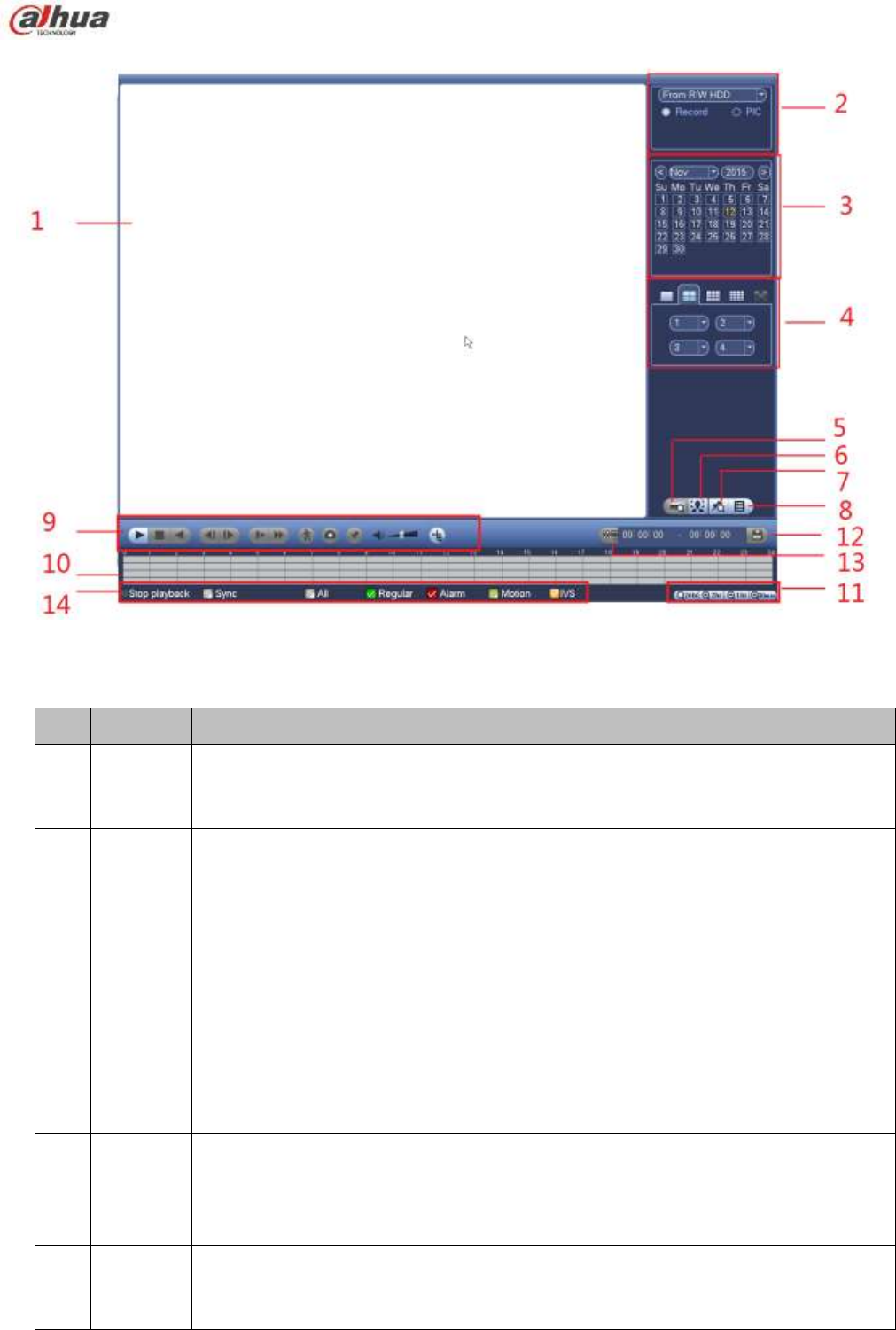
Figure 4-79
Please refer to the following sheet for more information.
SN
Name
Function
1
Display
window
Here is to display the searched picture or file.
Support 1/4/9/16-window playback. (It depends on the product channel
amount).
2
Search
type
Here you can select to search the picture or the recorded file.
You can select to play from the read-write HDD, from peripheral device or from
redundancy HDD.
Before you select to play from the peripheral device, please connect the
corresponding peripheral device. You can view all record files of the root directory
of the peripheral device. Click the Browse button; you can select the file you want to
play.
Important
Redundancy HDD does not support picture backup function, but it
supports picture playback function. You can select to play from redundancy
HDD if there are pictures on the redundancy HDD.
3
Calendar
The blue highlighted date means there is picture or file. Otherwise, there is no
picture or file.
In any play mode, click the date you want to see, you can see the
corresponding record file trace in the time bar.
4
Playback
mode
and
Playback mode:1/4/9/16. (It may vary due to different series.)
In 1-window playback mode: you can select 1-X channels (X depends on the
product channel amount).

196
channel
selection
pane.
In 4-window playback mode: you can select 4 channels according to your
requirement.
In 9-window playback mode, you can switch between 1-8, 9-16 and etc
channels.
In 16-window playback mode, you can switch between1-16, 17-32 and etc
channels.
The time bar will change once you modify the playback mode or the channel
option.
5
Card
number
search
The card number search interface is shown as below. Here you can view card
number/field setup bar. You can implement advanced search. Current series
product supports this function.
6
Face list
You can search when it is in 1-channel playback mode. Click it, system can filter all
human faces and generate human face list. Double click the file; system begins
playback the record or image of the corresponding human face.
7
Mark file
list button
Click it to go to mark file list interface. You can view all mark information of current
channel by time. Please refer to chapter 4.11.2.3 for detailed information.
Please note only the product of this icon supports mark function.
8
File list
switch
button
Double click it, you can view the picture/record file list of current day.
The file list is to display the first channel of the record file.
The system can display max 128 files in one time. Use the │and │ or the
mouse to view the file. Select one item, and then double click the mouse or click the
ENTER button to playback.
You can input the period in the following interface to begin accurate search.
File type:R—regular record; A—external alarm record;M—Motion detect
record.
Lock file. Click the file you want to lock and click the button to lock. The
file you locked will not be overwritten.
Search locked file: Click the button to view the locked file.
Return: Click button , system goes back to the calendar and channel setup
interface.
Please note:
For the file that is writing or overwriting, it can not be locked.
9
Playback
control
pane.
►/
Play/Pause
There are three ways for you to begin playback.
The play button
Double click the valid period of the time bar.
Double click the item in the file list.
In slow play mode, click it to switch between play/pause.
■
Stop
Backward play
In normal play mode, left click the button, the file begins backward play.
Click it again to pause current play.
In backward play mode, click ►/ to restore normal play.
│/
│
In playback mode, click it to play the next or the previous section. You can
click continuously when you are watching the files from the same channel.
In normal play mode, when you pause current play, you can click │ and
197
│ to begin frame by frame playback.
In frame by frame playback mode, click ►/ to restore normal playback.
►
Slow play
In playback mode, click it to realize various slow play modes such as slow
play 1, slow play 2, and etc.
Fast forward
In playback mode, click to realize various fast play modes such as fast
play 1,fast play 2 and etc.
Note: The actual play speed has relationship with the software version.
Smart search
The volume of the playback
Click the snapshot button in the full-screen mode, the system can snapshot
1 picture.
System supports custom snap picture saved path. Please connect the
peripheral device first, click snap button on the full-screen mode, you can
select or create path. Click Start button, the snapshot picture can be saved
to the specified path.
Mark button.
Please note this function is for some series product only. Please make sure
there is a mark button in the playback control pane.
You can refer to chapter 4.11.2.3 for detailed information.
In 1-channel playback mode, click it to enable/disable display IVS rule
information on the video.
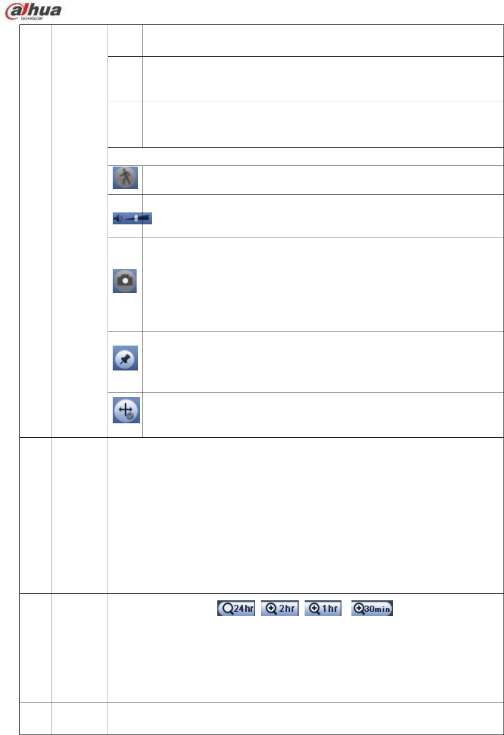
10
Time bar
It is to display the record type and its period in current search criteria.
In 4-window playback mode, there are corresponding four time bars. In other
playback mode, there is only one time bar.
Use the mouse to click one point of the color zone in the time bar, system
begins playback.
The time bar is beginning with 0 o'clock when you are setting the configuration.
The time bar zooms in the period of the current playback time when you are playing
the file.
The green color stands for the regular record file. The red color stands for the
external alarm record file. The yellow stands for the motion detect record file.
11
Time bar
unit
●The option includes: 、 、 和 ,. The smaller the unit,
the larger the zoom rate. You can accurately set the time in the time bar to playback
the record.
The time bar is beginning with 0 o'clock when you are setting the configuration.
The time bar zooms in the period of the current playback time when you are playing
the file.
12
Backup
Select the file(s) you want to backup from the file list. You can check from the
list. Then click the backup button, now you can see the backup menu. System
198
supports customized path setup. After select or create new folder, click the
Start button to begin the backup operation. The record file(s) will be saved in
the specified folder.
Check the file again you can cancel current selection. System max supports to
display 32 files from one channel.
After you clip on record file, click Backup button you can save it.
For one device, if there is a backup in process, you can not start a new backup
operation.
13
Clip
It is to edit the file.
Please click to play the file you want to edit.
Select clip start time on the time bar and then Click to start clip.
Select clip stop time on the time bar and then click to stop clip.
Click , system pops up file backup dialogue box for you to save.
Please note:
Clip function is for one-channel mode/multiple-channel mode.
System max supports 1024 files backup at the same time.
You can not operate clip operation if there is any file has been checked in
the file list.
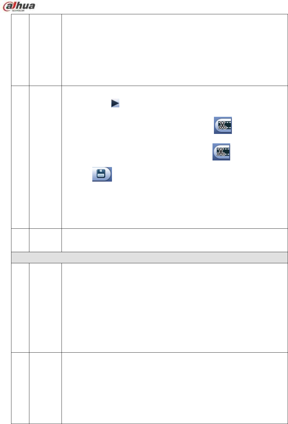
14
Record
type
In any play mode, the time bar will change once you modify the search type.
Other Functions
15
Smart
search
When system is playing, you can select a zone in the window to begin smart
search. Click the motion detect button to begin play.
Once the motion detect play has begun, click button again will terminate
current motion detect file play.
There is no motion detect zone by default.
If you select to play other file in the file list, system switches to motion detect
play of other file.
During the motion detect play process, you can not implement operations such
as change time bar, begin backward playback or frame by frame playback.
Please refer to chapter 4.11.2.1 Smart Search for detailed operation.
16
Other
channel
synchroni
zation
switch to
play
when
playback
When playing the file, click the number button, system can switch to the same
period of the corresponding channel to play.
199
17
Digital
zoom
When the system is in full-screen playback mode, left click the mouse in the
screen. Drag your mouse in the screen to select a section and then left click
mouse to realize digital zoom. You can right click mouse to exit.
18
Manually
switch
channel
when
playback
During the file playback process, you can switch to other channel via the
dropdown list or rolling the mouse.
This function is null if there is no record file or system is in smart search process.
Note:
All the operations here (such as playback speed, channel, time and progress) have relationship with
hardware version. Some series NVRs do not support some functions or playback speeds.
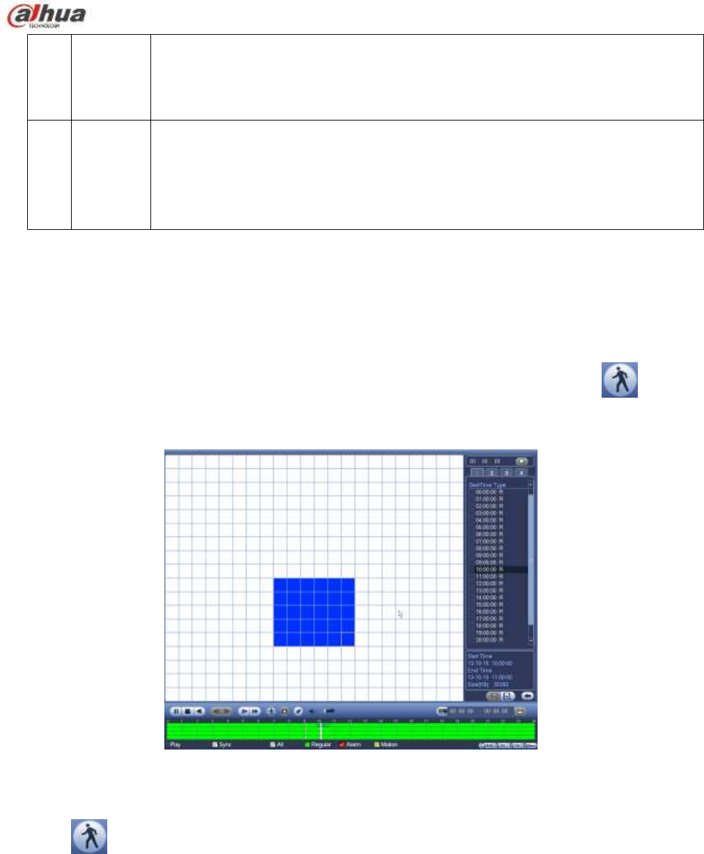
4.11.2.1 Smart Search
During the multiple-channel playback mode, double click one channel and then click the button,
system begins smart search. System supports 396(22*18 PAL) and 330(22*15 NTSC) zones. Please left
click mouse to select smart search zones. See Figure 4-80.
Figure 4-80
Click the , you can go to the smart search playback. Click it again, system stops smart search
playback.
Important
System does not support motion detect zone setup during the full-screen mode.
During the multiple-channel playback, system stops playback of rest channels if you
implement one-channel smart search.
4.11.2.2 Accurate playback by time
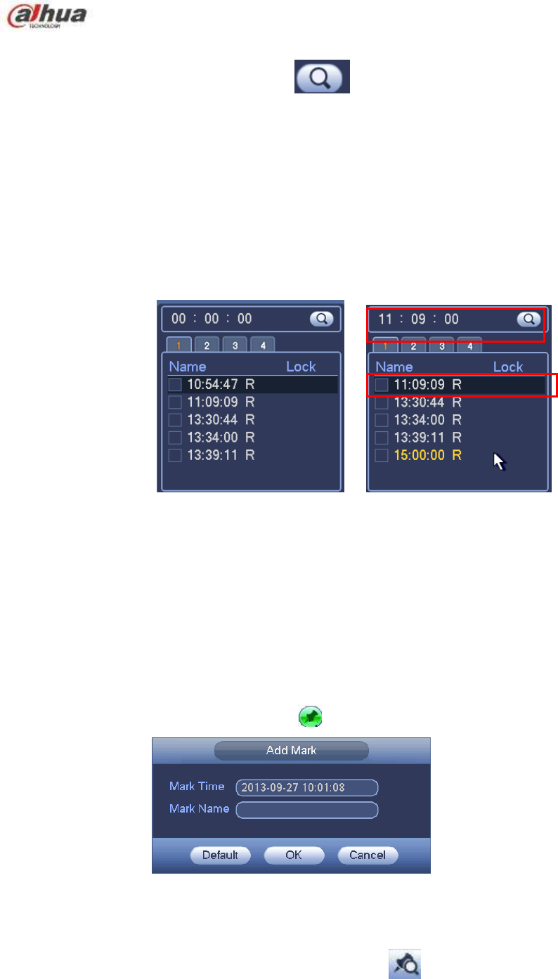
Select records from one day, click the list, you can go to the file list interface. You can input time at the top
200
right corner to search records by time. See image on the left side of the Figure 4-81 For example, input
time 11:00.00 and then click Search button , you can view all the record files after 11:00.00 (The
records includes current time.). See image on the right side of the Figure 4-81 Double click a file name to
playback.
Note
After you searched files, system implement accurate playback once you click Play for the first
time.
System does not support accurate playback for picture.
System supports synchronization playback and non-synchronous playback. The synchronization
playback supports all channels and non-synchronous playback only supports accurately
playback of current select channel.
Figure 4-81
4.11.2.3 Mark Playback
Please make sure your purchased device support this function. You can use this function only if
you can see the mark playback icon on the Search interface (Figure 4-79).
When you are playback record, you can mark the record when there is important information. After
playback, you can use time or the mark key words to search corresponding record and then play. It is very
easy for you to get the important video information.
Add Mark
When system is playback, click Mark button , you can go to the following interface. See Figure 4-82.
Figure 4-82
Playback Mark
During 1-window playback mode, click mark file list button in Figure 4-79, you can go to mark file list
interface. Double click one mark file, you can begin playback from the mark time.
Play before mark time
201
Here you can set to begin playback from previous N seconds of the mark time.
Note
Usually, system can playbacks previous N seconds record if there is such kind of record file. Otherwise,
system playbacks from the previous X seconds when there is such as kind of record.
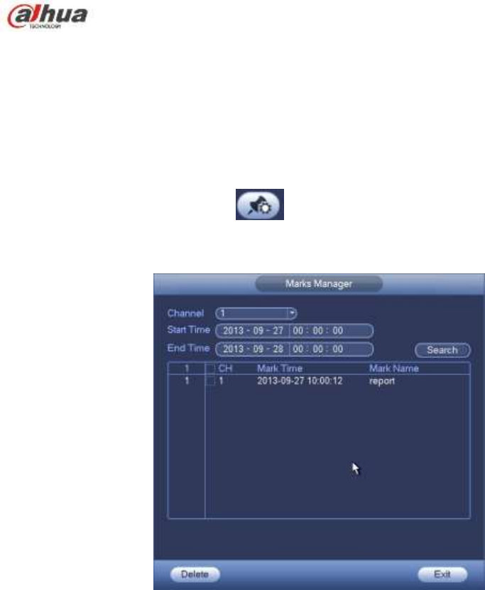
Mark Manager
Click the mark manager button on the Search interface (Figure 4-79); you can go to Mark
Manager interface. See Figure 4-83. System can manage all the record mark information of current
channel by default. You can view all mark information of current channel by time.
Figure 4-83
Modify
Double click one mark information item, you can see system pops up a dialogue box for you to change
mark information. You can only change mark name here.
Delete
Here you can check the mark information item you want to delete and then click Delete button, you can
remove one mark item. .
Note
After you go to the mark management interface, system needs to pause current playback. System
resume playback after you exit mark management interface.
If the mark file you want to playback has been removed, system begin playbacking from the first file
in the list.
4.11.3 Picture Playback
a) From Main menu->Search, or on the preview interface right click mouse, you can go to Figure
4-79.
b) At the top right pane, you can check the box to select picture and then select playback interval.
c) Please refer to chapter 4.11.2 to select picture you want to view.
202
4.12 Backup
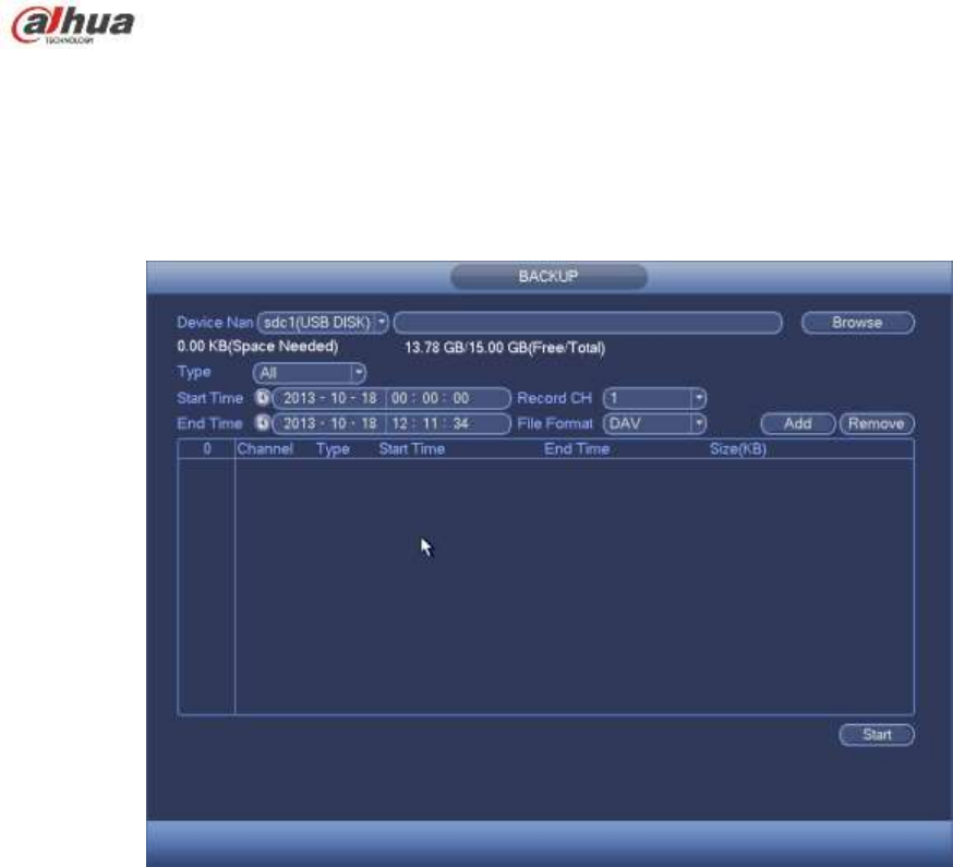
4.12.1 File Backup
In this interface, you can backup record file to the USB device.
a) Connect USB burner, USB device or portable HDD and etc to the device.
b) From Main menu->Backup, you can go to the Backup interface. See Figure 4-84
Figure 4-84
c) Select backup device and then set channel, file start time and end time.
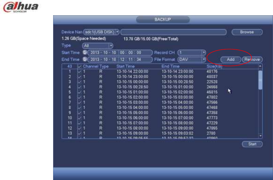
d) Click add button, system begins search. All matched files are listed below. System automatically
calculates the capacity needed and remained. See Figure 4-85.
e) System only backup files with a √ before channel name. You can use Fn or cancel button to
delete √ after file serial number.
f) Click backup button, you can backup selected files. There is a process bar for you reference.
g) When the system completes backup, you can see a dialogue box prompting successful backup.
203
Figure 4-85
h) Click backup button, system begins burning. At the same time, the backup button becomes stop
button. You can view the remaining time and process bar at the left bottom.
Note
During backup process, you can click ESC to exit current interface for other operation (For
some series product only). The system will not terminate backup process.
The file name format usually is: Channel number+Record type+Time. In the file name, the
YDM format is Y+M+D+H+M+S. File extension name is .dav.
4.12.2 Import/Export
This function allows you to copy current system configuration to other devices. It also supports import,
create new folder, and delete folder and etc function.
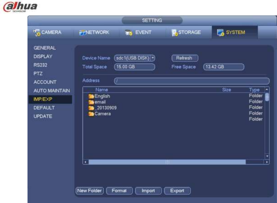
From Main menu->Setting->System->Import/Export, you can see the configuration file backup interface is
shown as below. See Figure 4-86.
204
Figure 4-86
Export: Please connect the peripheral device first and then go to the following interface. Click
Export button, you can see there is a corresponding ―Config_Time‖ folder. Double click the folder,
you can view some backup files.
Import: Here you can import the configuration files from the peripheral device to current device. You
need to select a folder first. You can see a dialogue box asking you to select a folder if you are
selecting a file. System pops up a dialogue box if there is no configuration file under current folder.
After successfully import, system needs to reboot to activate new setup.
Format: Click Format button, system pops up a dialogue box for you to confirm current operation.
System begins format process after you click the OK button.
Note:
System can not open config backup interface again if there is backup operation in the process.
System refreshes device when you go to the config backup every time and set current directory as
the root directory of the peripheral device.
If you go to the configuration backup interface first and then insert the peripheral device, please click
Refresh button to see the newly added device.
4.12.3 Backup Log
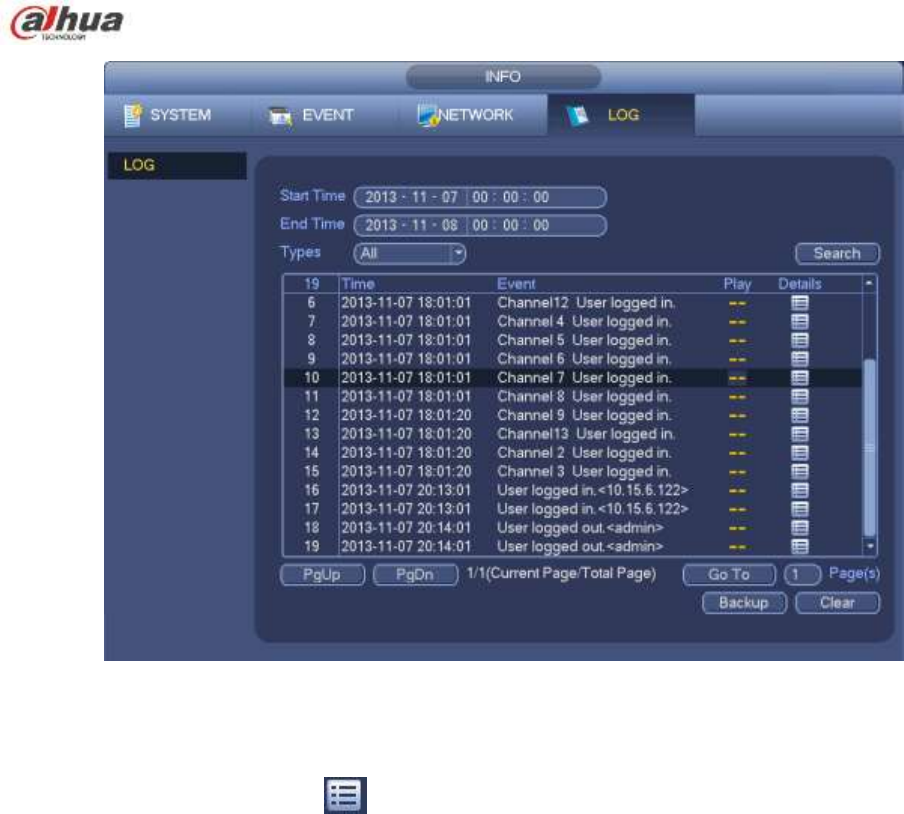
a) From Main menu->Info->Log, the interface is shown as below. See Figure 4-87.
205
Figure 4-87
b) Select log type and then set start time/end time, click Search button, you can see log time and
event information. Click to view detailed log information.
c) Select log items you want to save and then click backup button, you can select a folder to save
them. Click Start to backup and you can see the corresponding dialogue box after the process is
finish.
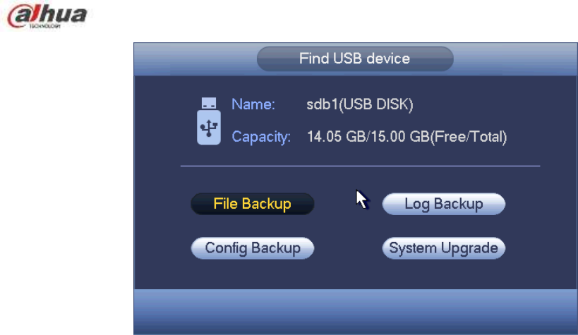
4.12.4 USB Device Auto Pop-up
After you inserted the USB device, system can auto detect it and pop up the following dialogue box. It
allows you to conveniently backup file, log, configuration or update system. See Figure 4-88. Please refer
to chapter 4.12.1 file backup, chapter 4.12.3 backup log, chapter 4.12.2 import/export, and chapter 4.11.2
search for detailed information.
206
Figure 4-88
4.13 Alarm
4.13.1 Detect Alarm
In the main menu, from Setting to Detect, you can see motion detect interface. See Figure 4-89.There
are three detection types: motion detection, video loss, tampering.
4.13.1.1 Motion Detect
After analysis video, system can generate a motion detect alarm when the detected moving signal
reached the sensitivity you set here.
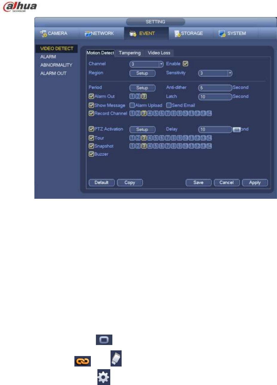
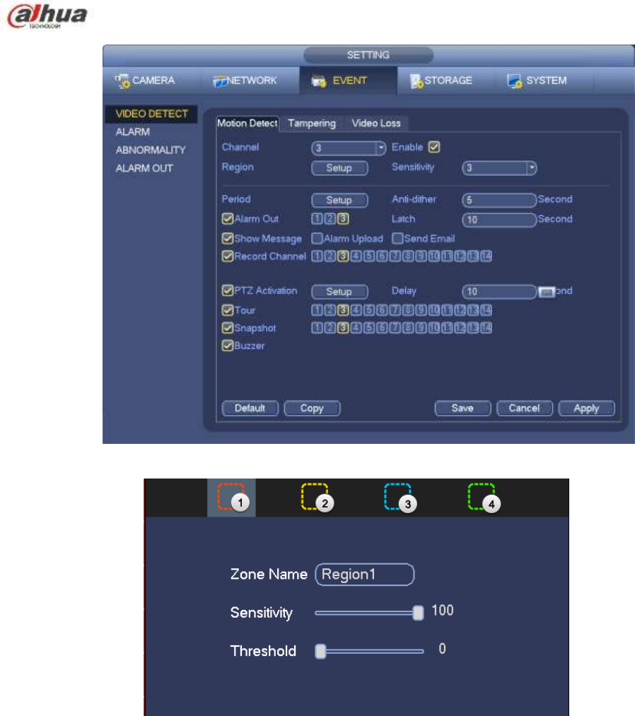
Detection menu is shown as below. See Figure 4-89.
Event type: From the dropdown list you can select motion detection type.
Channel: Select a channel from the dropdown list to set motion detect function.
Enable: Check the box here to enable motion detect function.
Region: Click select button, the interface is shown as in Figure 4-90. Here you can set motion
detection zone. There are four zones for you to set. Please select a zone first and then left drag the
mouse to select a zone. The corresponding color zone displays different detection zone. You can
click Fn button to switch between the arm mode and disarm mode. In arm mode, you can click the
direction buttons to move the green rectangle to set the motion detection zone. After you completed
the setup, please click ENTER button to exit current setup. Do remember click save button to save
current setup. If you click ESC button to exit the region setup interface system will not save your
zone setup.
Sensitivity: System supports 6 levels. The sixth level has the highest sensitivity.
Anti-dither: Here you can set anti-dither time. The value ranges from 5 to 600s. The anti-dither time
refers to the alarm signal lasts time. It can be seem as the alarm signal activation stays such as the
buzzer, tour, PTZ activation, snapshot, channel record. The stay time here does not include the latch
time. During the alarm process, the alarm signal can begin an anti-dither time if system detects the
local alarm again. The screen prompt, alarm upload, email and etc will not be activated. For example,
if you set the anti-dither time as 10 second, you can see the each activation may last 10s if the local
alarm is activated. During the process, if system detects another local alarm signal at the fifth
second, the buzzer, tour, PTZ activation, snapshot, record channel will begin another 10s while the

207
screen prompt, alarm upload, email will not be activated again. After 10s, if system detects another
alarm signal, it can generate an alarm since the anti-dither time is out.
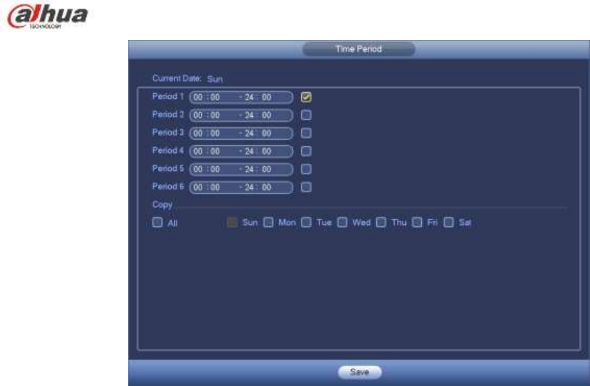
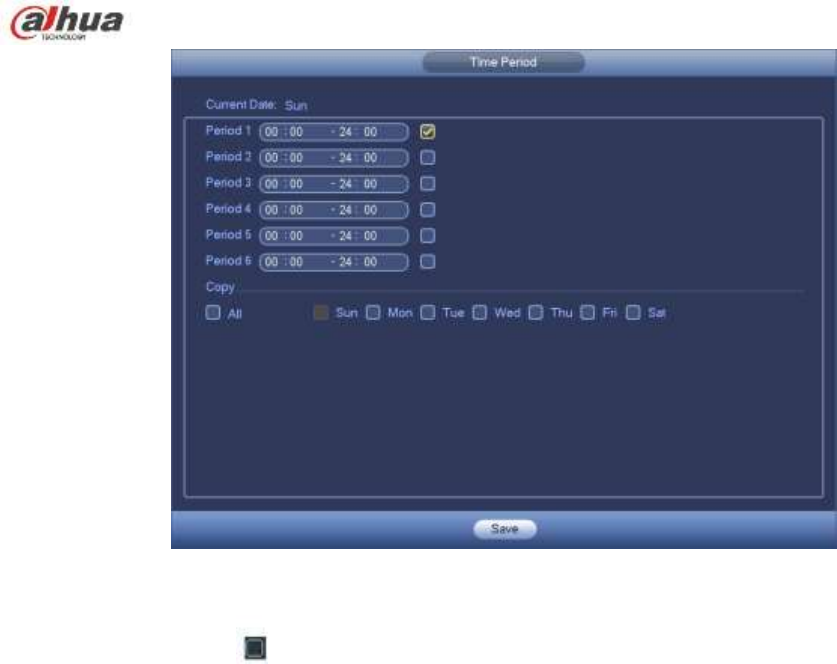
Period: Click set button, you can see an interface is shown as in Figure 4-92. Here you can set
motion detect period. System only enables motion detect operation in the specified periods. It is not
for video loss or the tampering. There are two ways for you to set periods. Please note system only
supports 6 periods in one day.
In Figure 4-92, Select icon of several dates, all checked items can be edited together. Now
the icon is shown as . Click to delete a record type from one period.
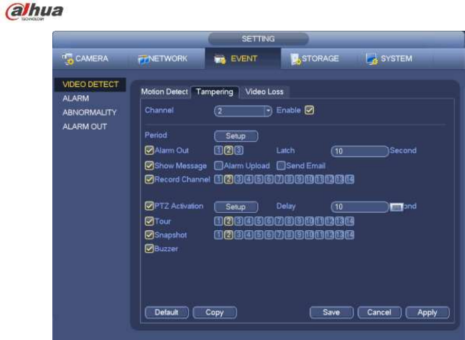
In Figure 4-92. Click button after one date or a holiday, you can see an interface shown as in
Figure 4-93. There are four record types: regular, motion detection (MD), Alarm, MD & alarm.
Alarm output: when an alarm occurs, system enables peripheral alarm devices.
Latch: when motion detection complete, system auto delays detecting for a specified time. The value
ranges from 1-300(Unit: second)
Show message: System can pop up a message to alarm you in the local host screen if you enabled
this function.
Alarm upload: System can upload the alarm signal to the network (including alarm centre) if you
enabled current function.
Send email: System can send out email to alert you when an alarm occurs.
Record channel: System auto activates motion detection channel(s) to record once an alarm occurs.
Please make sure you have set MD record in Schedule interface(Main Menu->Setting->Schedule)
and schedule record in manual record interface(Main Menu->Advanced->Manual Record)
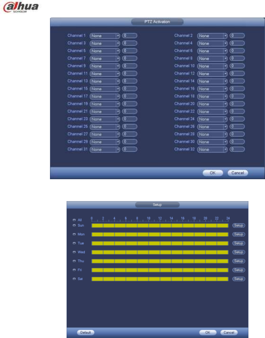
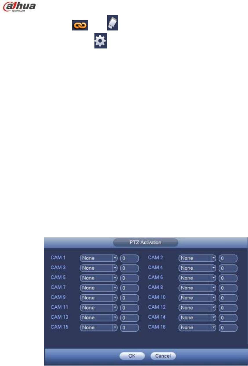
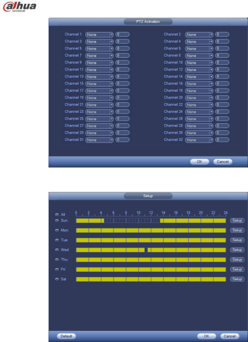
PTZ activation: Here you can set PTZ movement when an alarm occurs. Such as go to preset, tour
&pattern when there is an alarm. Click ―select‖ button, you can see an interface is shown as in Figure
4-91X.
Record Delay: System can delay the record for specified time after alarm ended. The value ranges
from 10s to 300s.
Tour: Here you can enable tour function when alarm occurs. System one-window tour.
Snapshot: You can enable this function to snapshoot image when a motion detect alarm occurs.
Video matrix Check the box here to enable this function. When an alarm occurs, SPOT OUT port
displays device video output. It displays video (1-window tour) from alarm activation channel you
select at the Record channel item.
Buzzer: Highlight the icon to enable this function. The buzzer beeps when alarm occurs.
Please highlight icon to select the corresponding function. After all the setups please click save
button, system goes back to the previous menu.
Note:
In motion detection mode, you can not use copy/paste to set channel setup since the video in each
channel may not be the same.
In Figure 4-90, you can left click mouse and then drag it to set a region for motion detection. Click Fn to
switch between arm/withdraw motion detection. After setting, click enter button to exit.
208
Figure 4-89
Figure 4-90
209
Figure 4-91
Figure 4-92
210
Figure 4-93
Motion detect here only has relationship with the sensitivity and region setup. It has no relationship
with other setups.
4.13.1.2 Tampering
When someone viciously masks the lens, or the output video is in one-color due to the environments
light change, the system can alert you to guarantee video continuity. Tampering interface is shown as
in Figure 4-94. You can enable ―Alarm output ―or ―Show message‖ function when tampering alarm
occurs.
Sensitivity: The value ranges from 1 to 6. It mainly concerns the brightness. The level 6 has the
higher sensitivity than level 1. The default setup is 3.
Tips:
You can enable preset/tour/pattern activation operation when video loss occurs.
Please refer to chapter 4.13.1.1 motion detection for detailed information.
Note:
In Detect interface, copy/paste function is only valid for the same type, which means you can not
copy a channel setup in video loss mode to tampering mode.
About Default function. Since detection channel and detection type may not be the same, system
can only restore default setup of current detect type. For example, if you click Default button at
the tampering interface, you can only restore default tampering setup. It is null for other detect
types.
System only enables tampering function during the period you set here. It is null for motion detect
or video loss type.
211
Figure 4-94
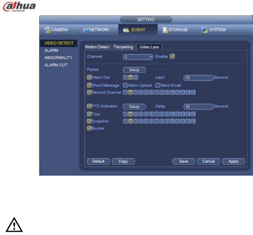
4.13.1.3 Video Loss
In Figure 4-89, select video loss from the type list. You can see the interface is shown as in Figure
4-95. This function allows you to be informed when video loss phenomenon occurred. You can
enable alarm output channel and then enable show message function.
You can refer to chapter 4.13.1.1Motion detect for detailed information.
Tips:
You can enable preset/tour/pattern activation operation when video loss occurs.
212
Figure 4-95
4.13.2 IVS (Optional)
Please make sure you are connecting to the smart network camera, otherwise you can not
use IVS function!
From main menu->Setting->Event, you can go to the IVS interface. It includes four interfaces:
Tripwire/intrusion/object/scene.
4.13.2.1 Tripwire (Optional)
Please make sure you are connecting to the smart network camera, otherwise you can not use
IVS function!
System generates an alarm once there is any object crossing the tripwire in the specified direction.
From main menu->Setting->Event->IVS->Tripwire, the interface is shown as below. See Figure 4-96.
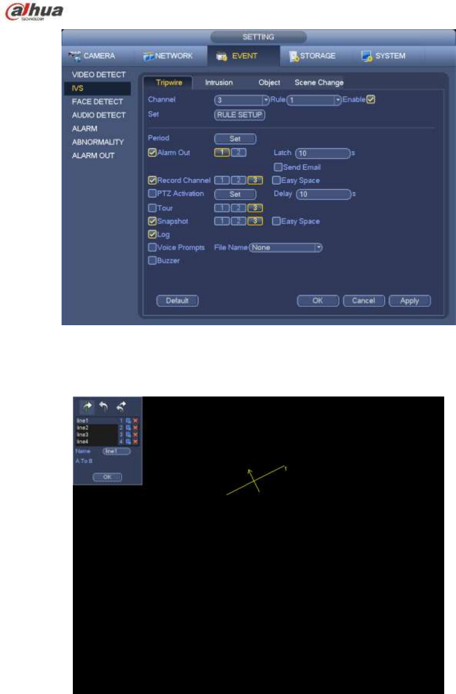
214
Direction ( / / ): System can generate an alarm once there is any object crossing in the
specified direction.
Now you can draw a rule. Left click mouse to draw a tripwire. The tripwire can be a direct line, curve or
polygon. Right click mouse to complete.
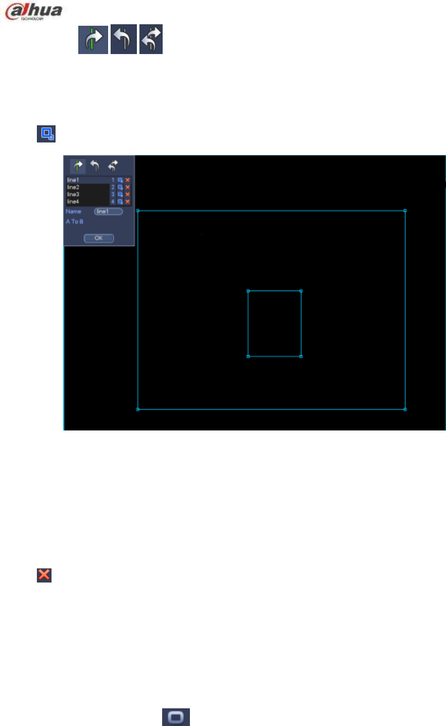
Click to draw filter object.
Figure 4-98
Select the blue line and then use mouse to adjust zone size.
Note
Each rule can set two sizes (min size/max size). Once the object is smaller than the min size or larger
than the max size, there is no alarm. Please make sure the max size is larger than the min size.
Click Ok to complete the rule setup.
Tips
Click to delete the corresponding rule.
You can refer to the following information to set other parameters.
Channel: Select a channel from the dropdown list to set tripwire function.
Enable: Check the box here to enable tripwire function.
Rule: input customized rule name here.
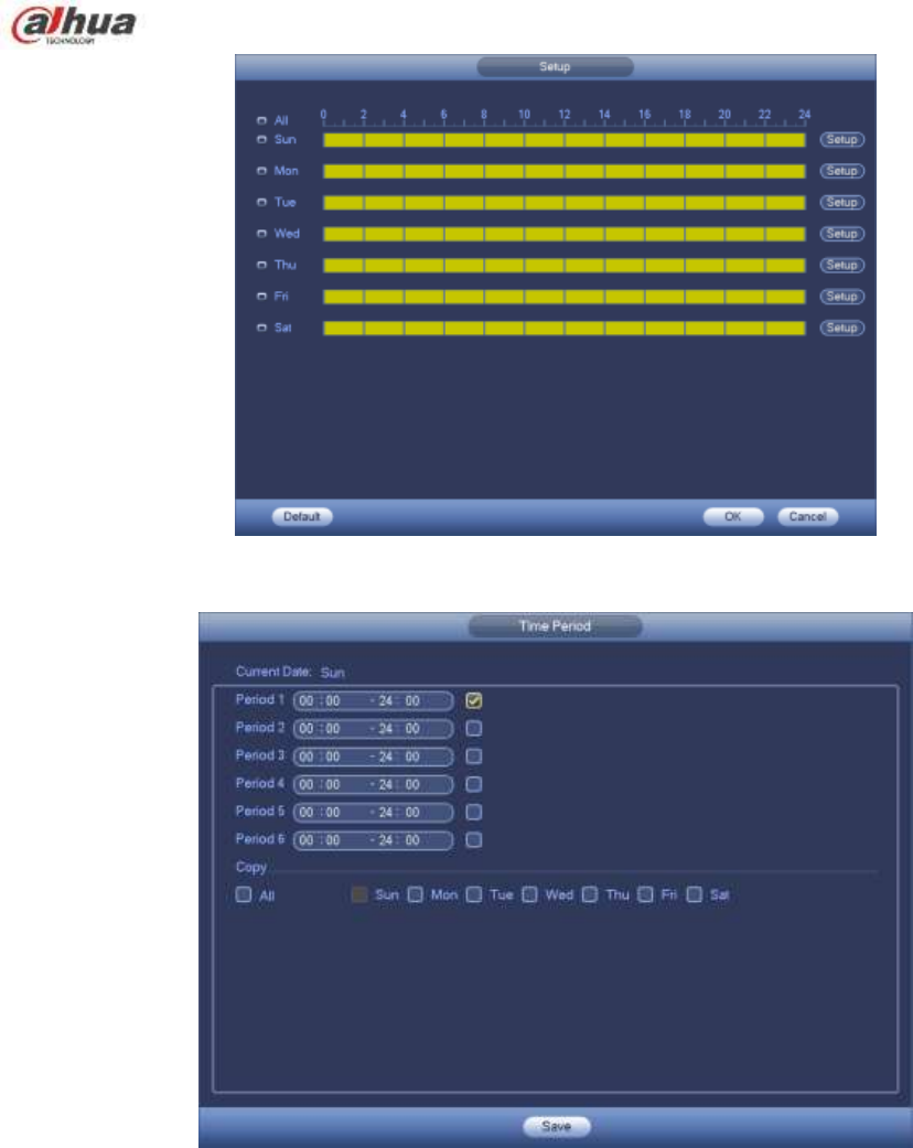
Period: Click set button, you can see an interface is shown as in Figure 4-92. Here you can set
tripwire period. System only enables tripwire operation in the specified periods. There are two ways
for you to set periods. Please note system only supports 6 periods in one day.
In Figure 4-92, Select icon of several dates, all checked items can be edited together. Now
215
the icon is shown as . Click to delete a record type from one period.
In Figure 4-92. Click button after one date or a holiday, you can see an interface shown as in
Figure 4-93.
Alarm output: when an alarm occurs, system enables peripheral alarm devices.
Latch: when tripwire complete, system auto delays detecting for a specified time. The value ranges
from 1-300(Unit: second)
Show message: System can pop up a message to alarm you in the local host screen if you enabled
this function.
Alarm upload: System can upload the alarm signal to the network (including alarm centre) if you
enabled current function.
Send email: System can send out email to alert you when an alarm occurs.
Record channel: System auto activates tripwire channel(s) to record once an alarm occurs. Please
make sure you have set intelligent record in Schedule interface(Main Menu->Setting->Schedule)
and schedule record in manual record interface(Main Menu->Advanced->Manual Record)
PTZ activation: Here you can set PTZ movement when an alarm occurs. Such as go to preset, tour
&pattern when there is an alarm. Click “select” button, you can see an interface is shown as in
Figure 4-91X.
Record Delay: System can delay the record for specified time after alarm ended. The value ranges
from 10s to 300s.
Tour: Here you can enable tour function when an alarm occurs. System one-window tour.
Snapshot: You can enable this function to snapshot image when a motion detect alarm occurs.
Buzzer: Highlight the icon to enable this function. The buzzer beeps when an alarm occurs.
Figure 4-99
216
Figure 4-100
Figure 4-101
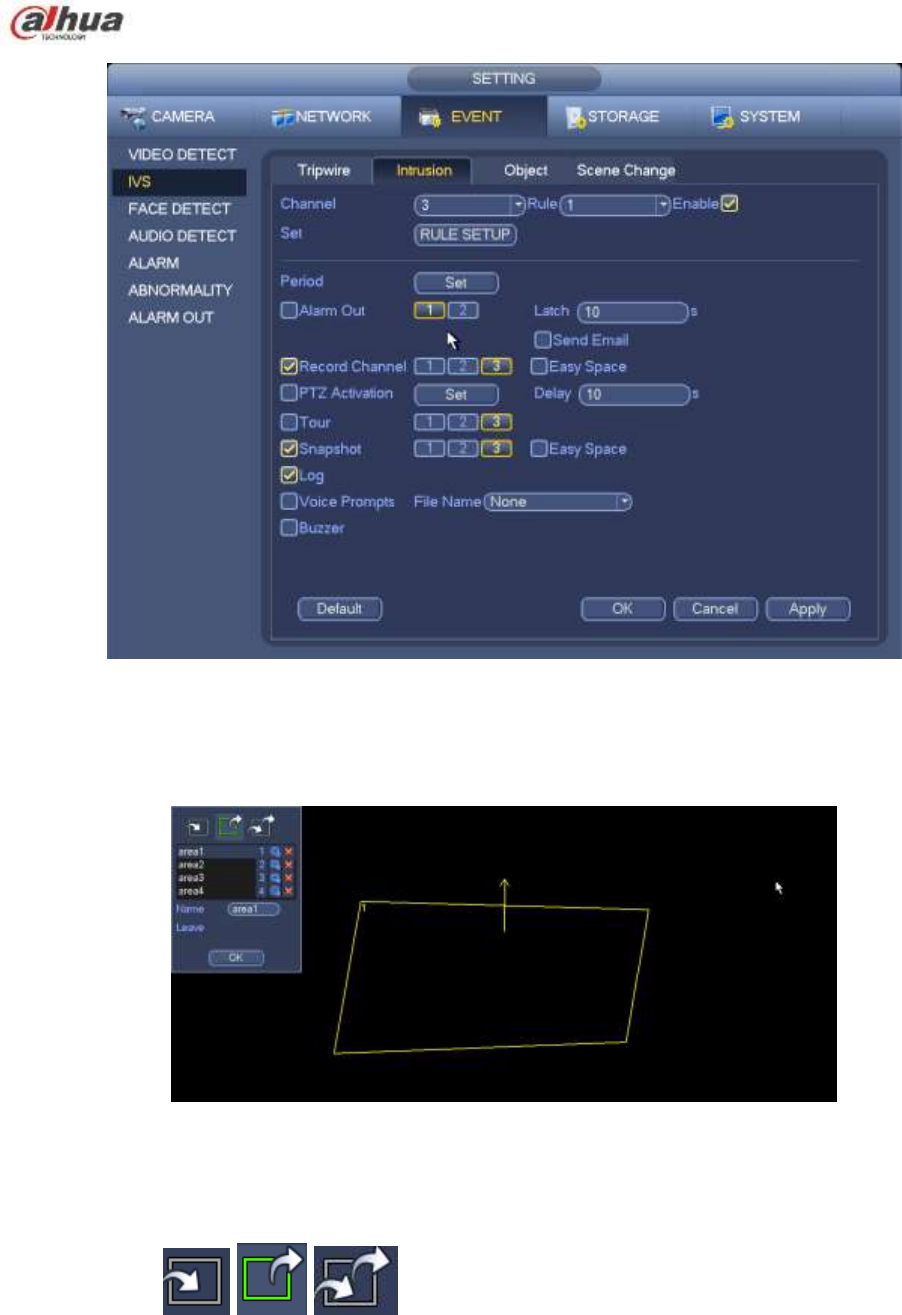
4.13.2.2 Intrusion (Cross warning zone) (Optional)
Please make sure you are connecting to the smart network camera, otherwise you can not use
IVS function!
System generates an alarm once there is any object entering or exiting the zone in the specified direction.
From main menu->Setting->Event->IVS->Intrusion, the intrusion interface is shown as below. See Figure
4-102.
217
Figure 4-102
Check the enable box to enable intrusion function.
Click Rule setup to draw the zone. See Figure 4-103.
Figure 4-103
Select SN (Area1/2/3/4) and direction, and then input customized rule name.
Area1/2/3/4: System supports four zones. Each SN stands for one zone.
Direction ( / / ): System can generate an alarm once there is any object
enter/exit (Or both) the zone.
Now you can draw a rule. Left click mouse to draw a line first and then right click mouse to draw another
line until you draw a rectangle, you can right click mouse to exit.
Click Ok to complete the rule setup.
Tips
218
Click to delete the corresponding rule.
You can refer to the chapter 4.13.2.1 to set parameters.
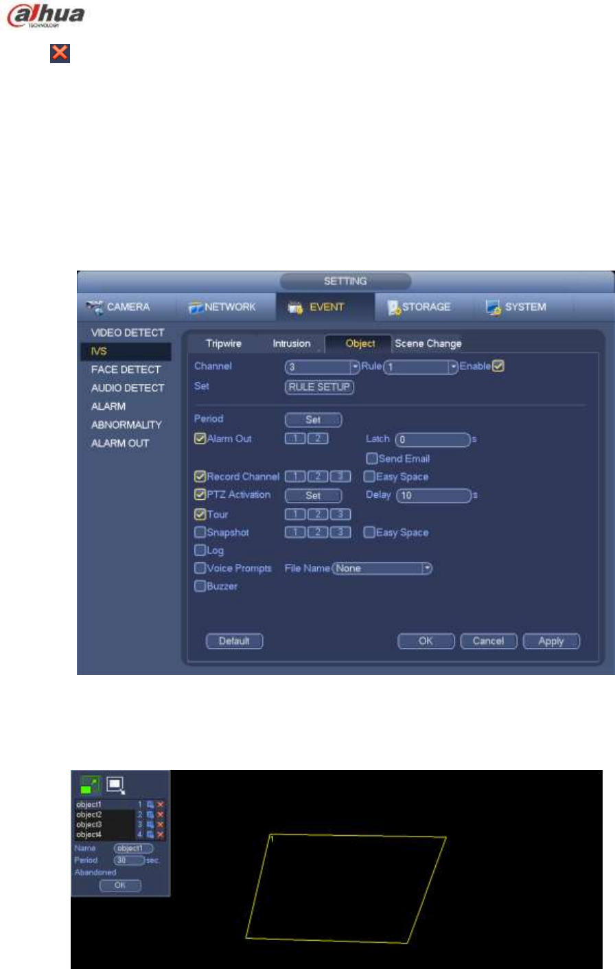
4.13.2.3 Object Detect (Optional)
Please make sure you are connecting to the smart network camera, otherwise you can not
use IVS function!
For the same channel, the object detect and the intrusion can not be valid at the same time.
System generates an alarm when the object missing/abandoned object alarm occurs.
From main menu->Setting->Event->IVS->Object, the object interface is shown as below. See Figure
4-104.
Figure 4-104
Check the enable box to enable object detect function.
Click Rule setup to draw the rule.
Figure 4-105
219
Select SN (object1/2/3/4) and direction, and then input customized rule name.
Object1/2/3/4: System supports four zones. Each SN stands for one zone.
Direction ( / ): For icon , system can generate an alarm once the object left in the
one for the specified time.. For icon , system can generate an alarm once the object is out of
the zone for the specified time.
Period: It refers to the object in/out the zone time.
Now you can draw a rule. Left click mouse to draw a line, until you draw a rectangle, you can right click
mouse.
Click Ok to complete the rule setup.
Tips
Click to delete the corresponding rule.
You can refer to the chapter 4.13.2.1 to set parameters.
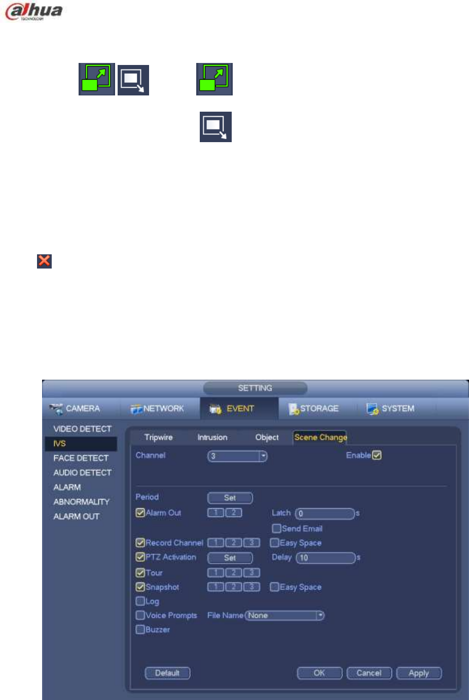
4.13.2.4 Scene Change (Optional)
Please make sure you are connecting to the smart network camera, otherwise you can not use
IVS function!
When the detected scene changes, system can generate an alarm.
From main menu->Setting->Event->IVS->Scene change, the interface is shown as in Figure 4-106.
Figure 4-106
You can refer to the chapter 4.13.2.1 to set parameters.
220
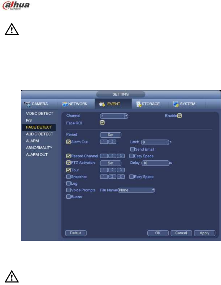
4.13.3 Face Detect (Optional)
Please make sure you are connecting to the smart network camera, otherwise you can not
use IVS function!
When camera detects human face, system can generate an alarm.
From main menu->Setting->Event->Face detect, the interface is shown as in Figure 4-107.
Face ROI: Check the box here, system can enhance the human face display pane.
Log: Check the box here, system can record face detect log.
You can refer to the chapter 4.13.2.1 t to set other parameters.
Figure 4-107
4.13.4 Audio Detect (Optional)
Please make sure you are connecting to the smart network camera, otherwise you can not
use IVS function!
System can generate an alarm once it detect the audio input is abnormal or audio volume changes.
From main menu->Setting->Event->Audio detect, you can see an interface shown as in Figure 4-108.
Input abnormal: Check the box here, system can generate an alarm once the audio input is
abnormal.
Intensity change: Check the box here, system can generate an alarm once the audio volume
becomes strong.
Sensitivity: It refers to the audio recognition sensitivity. The higher the value is, the higher the
sensitivity is.
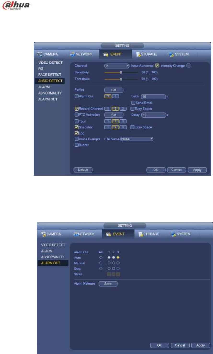
221
Threshold: It is to set intensity change threshold. The smaller the value is, the higher the sensitivity
is.
Log: Check the box here, system can record audio detect alarm log.
You can refer to the chapter 4.13.2.1 t to set other parameters.
Figure 4-108
4.13.5 Alarm output
From Main menu->Setting->Event->Alarm output, you can see an interface shown as in Figure 4-109.
Here is for you to set proper alarm output (Auto/manual/stop).
Click OK button of the alarm reset, you can clear all alarm output status.

222
Figure 4-109
Please highlight icon to select the corresponding alarm output.
After all the setups please click OK button, system goes back to the previous menu.
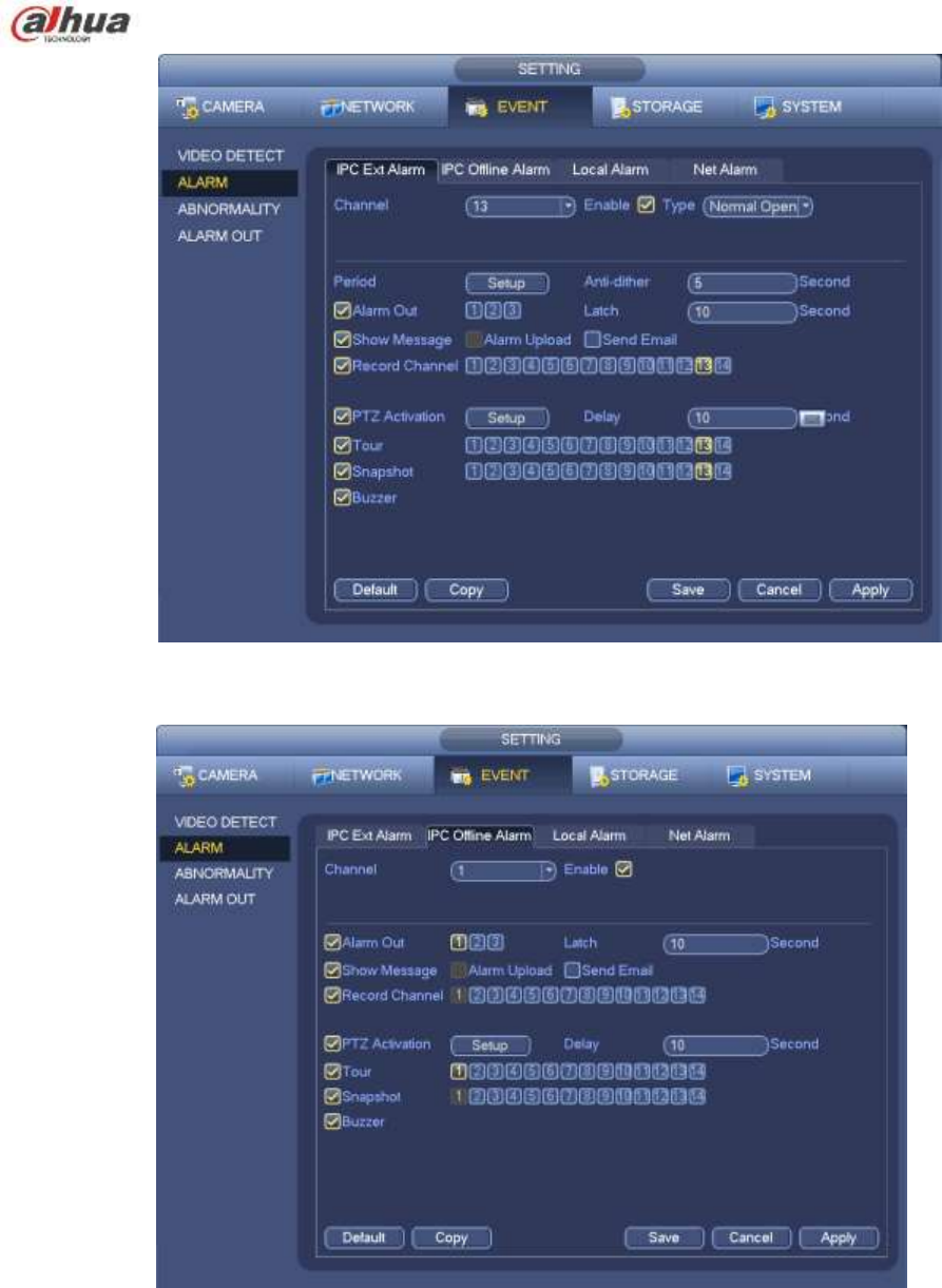
4.13.6 Alarm Setup
In the main menu, from Setting->Event->Alarm, you can see alarm setup interface.
Alarm in: Here is for you to select channel number.
In the main menu, from Setting->Event->Alarm, you can see alarm setup interface. See Figure 4-110.
There are four alarm types. See Figure 4-110 to Figure 4-113.
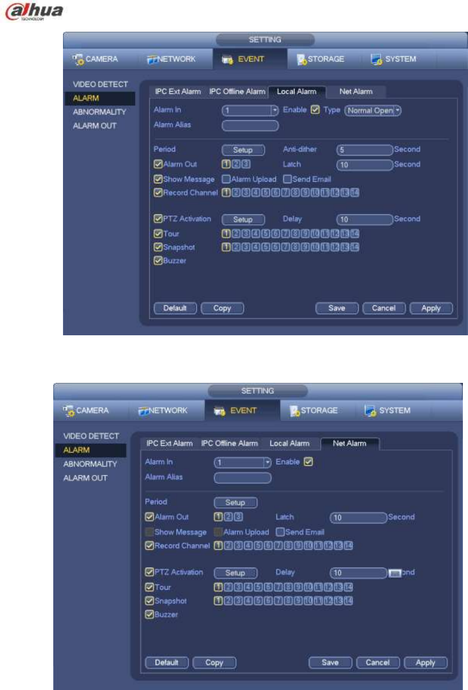
Local alarm: The alarm signal system detects from the alarm input port.
Network alarm: It is the alarm signal from the network.
IPC external alarm: It is the on-off alarm signal from the front-end device and can activate the local
HNVR.
IPC offline alarm: Once you select this item, system can generate an alarm when the front-end IPC
disconnects with the local HNVR. The alarm can activate record, PTZ, snap and etc. The alarm can
last until the IPC and the HNVR connection resumes.
Important
If it is your first time to boot up the device, the disconnection status of the front-end
network camera will not be regarded as offline. After one successfully connection, all
the disconnection events will be regarded as IPC offline event.
When IPC offline alarm occurs, the record and snapshot function of digital channel is
null.
Enable: Please you need to highlight this button to enable current function.
Type: normal open or normal close.
Period: Click set button, you can see an interface is shown as in Figure 4-115. There are two ways
for you to set periods. There are max 6 periods in one day. There are four record types: regular,
motion detection (MD), Alarm, MD & alarm.
In Figure 4-115, Select icon of several dates, all checked items can be edited together.
Now the icon is shown as . Click to delete a record type from one period.
In Figure 4-115. Click button after one date or a holiday, you can see an interface shown
as in Figure 4-116. There are four record types: regular, motion detection (MD), Alarm, MD &
alarm.
PTZ activation: When an alarm occurred, system can activate the PTZ operation. The PTZ activation
lasts an anti-dither period. See Figure 4-114.
Anti-dither: Here you can set anti-dither time. The value ranges from 5 to 600s. The anti-dither time
refers to the alarm signal lasts time. It can be seem as the alarm signal activation stays such as the
buzzer, tour, PTZ activation, snapshot, channel record. The stay time here does not include the latch
time. During the alarm process, the alarm signal can begin an anti-dither time if system detects the
local alarm again. The screen prompt, alarm upload, email and etc will not be activated. For example,
if you set the anti-dither time as 10 second, you can see the each activation may last 10s if the local
alarm is activated. During the process, if system detects another local alarm signal at the fifth
second, the buzzer, tour, PTZ activation, snapshot, record channel will begin another 10s while the

223
screen prompt, alarm upload, email will not be activated again. After 10s, if system detects another
alarm signal, it can generate an alarm since the anti-dither time is out.
Alarm output: The number here is the device alarm output port. You can select the corresponding
ports(s) so that system can activate the corresponding alarm device(s) when an alarm occurred.
Latch: When the anti-dither time ended, the channel alarm you select in the alarm output may last
the specified period. The value ranges from 1 to 300 seconds. This function is not for other alarm
activation operations. The latch is still valid even you disable the alarm event function directly.
Show message: System can pop up a message to alarm you in the local host screen if you enabled
this function.
Alarm upload: System can upload the alarm signal to the network (including alarm centre and the
WEB) if you enabled current function. System only uploads the alarm channel status. You can go
to the WEB and then go to the Alarm interface to set alarm event and alarm operation. Please go
to the Network interface to set alarm centre information.
Send email: System can send out the alarm signal via the email to alert you when alarm occurs.
Once you enable the snap function, system can also send out an image as the attachment. Please
go to the Main Menu->Setting ->Network->Email interface to set.
Record channel: you can select proper channel to record alarm video (Multiple choices).
You need to set alarm record mode as Schedule in Record interface (Main
Menu->Advanced->Record). Please note the manual record has the highest priority. System
record all the time no matter there is an alarm or not if you select Manual mode.
Now you can go to the Schedule interface (Main Menu->Setting->Schedule) to set the record
type, corresponding channel number, week and date. You can select the record
type:Regular/MD/Alarm/MD&Alarm. Please note, you can not select the MD&Alarm and MD(or
Alarm) at the same time.
Now you can go to the Encode interface to select the alarm record and set the encode
parameter (Main Menu->Setting->Encode).
Finally, you can set the alarm input as the local alarm and then select the record channel. The
select channel begins alarm record when an alarm occurred. Please note system begins the
alarm record instead of the MD record if the local alarm and MD event occurred at the same
time.
Tour: Here you can enable tour function when an alarm occurs. System supports 1/8-window tour.
Please go to chapter4.7.4.2 Display for tour interval setup. Please note the tour setup here has
higher priority than the tour setup you set in the Display interface. Once there two tours are both
enabled, system can enable the alarm tour as you set here when an alarm occurred. If there is no
alarm, system implements the tour setup in the Display interface.
Snapshot: You can enable this function to snapshoot image when an alarm occurs.
Buzzer: Highlight the icon to enable this function. The buzzer beeps when an alarm occurs.
224
Figure 4-110
Figure 4-111
225
.
Figure 4-112
Figure 4-113
226
Figure 4-114
Figure 4-115
227
Figure 4-116
Please highlight icon to select the corresponding function. After setting all the setups please
click save button, system goes back to the previous menu.
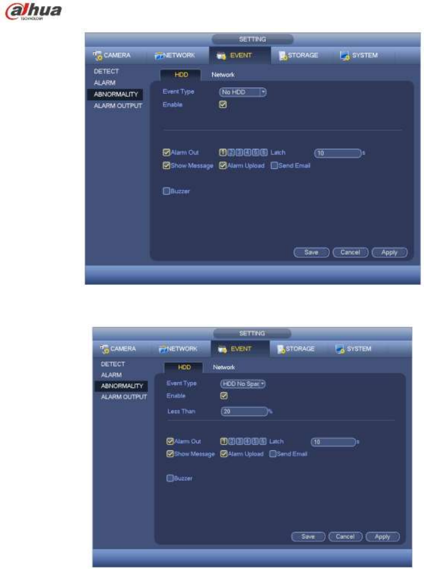
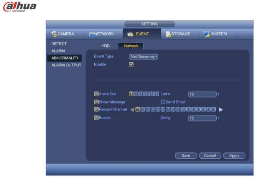
4.13.7 Abnormality
There are two types: Disk/Network.
Disk: Disk error, no disk, no space. See Figure 4-117 and Figure 4-118.
Network: Disconnection, IP conflict, MAC conflict. See Figure 4-119.
Alarm output: Please select alarm activation output port (multiple choices).
Less than: System can alarm you when the HDD space is less than the threshold you set here
(For HDD no space type only).
Latch: Here you can set corresponding delaying time. The value ranges from 1s-300s. System
automatically delays specified seconds in turning off alarm and activated output after external alarm
cancelled.
Show message: system can pop up the message in the local screen to alert you when alarm
occurs.
Alarm upload: System can upload the alarm signal to the network (including alarm centre) if you
enabled current function. For disconnection event, IP conflict event and MAC conflict event, this
function is null.
Send email: System can send out email to alert you when alarm occurs.
Buzzer: Highlight the icon to enable this function. The buzzer beeps when an alarm occurs.
228
Figure 4-117
Figure 4-118
229
Figure 4-119
4.14 Network
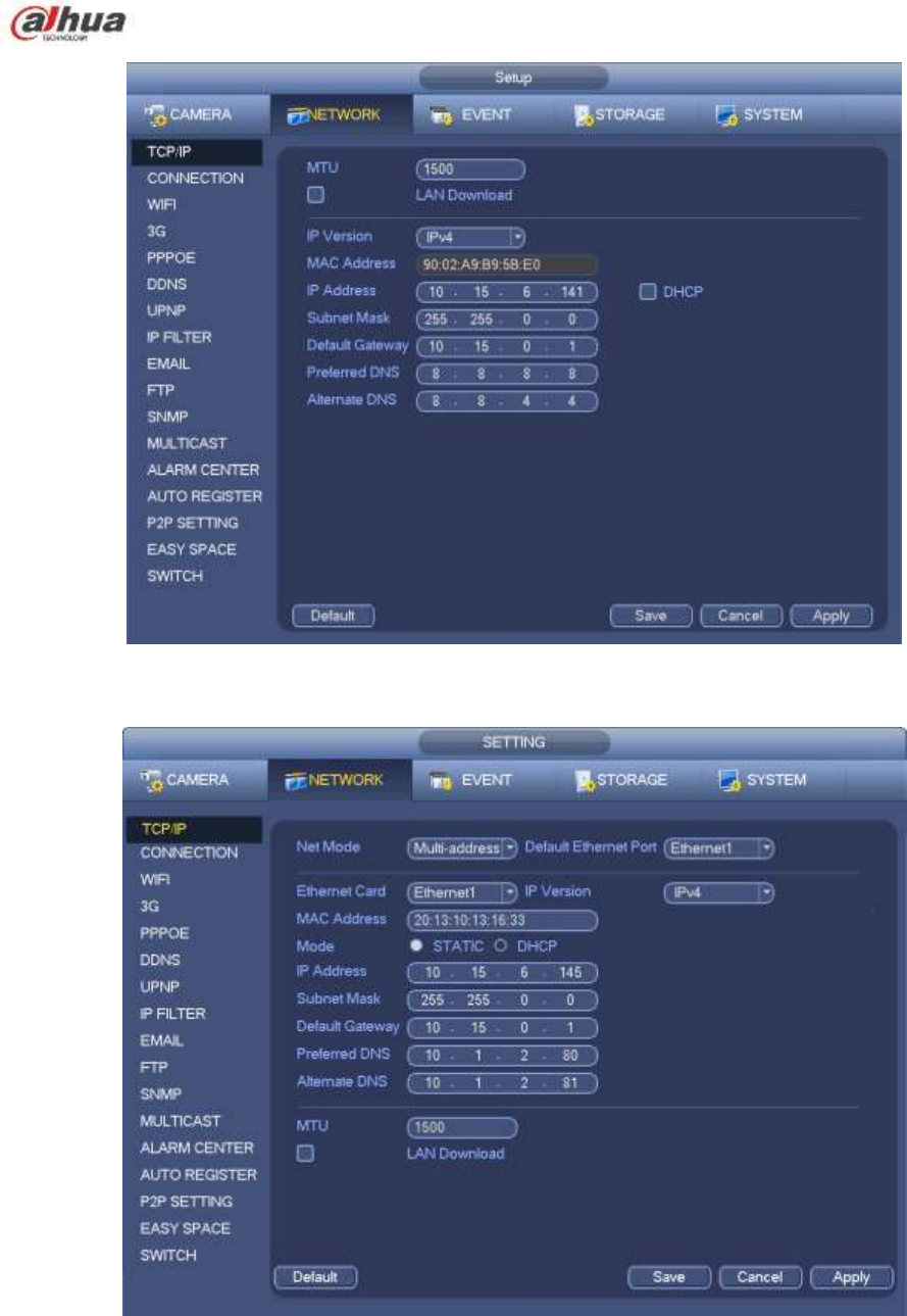
4.14.1.1 TCP/IP
The single network adapter interface is shown as in Figure 4-120 and the dual network adapters interface
is shown as in Figure 4-121.
Network Mode : Includes multiple access, fault tolerance, and load balancing
Multiple-address mode: eth0 and eth1 operate separately. You can use the services such as
HTTP, RTP service via etho0 or the eth1. Usually you need to set one default card (default setup
is etho) to request the auto network service form the device-end such as DHCP, email, FTP and
etc. In multiple-address mode, system network status is shown as offline once one card is
offline.
Network fault-tolerance: In this mode, device uses bond0 to communicate with the external
devices. You can focus on one host IP address. At the same time, you need to set one master
card. Usually there is only one running card (master card).System can enable alternate card
when the master card is malfunction. The system is shown as offline once these two cards are
both offline. Please note these two cards shall be in the same LAN.
Load balance: In this mode, device uses bond0 to communicate with the external device. The
eth0 and eth1 are both working now and bearing the network load. Their network load are
general the same. The system is shown as offline once these two cards are both offline. Please
note these two cards shall be in the same LAN.
Default Network Card: Please select eth0/eth1/bond0(optional) after enable multiple-access
function
Main Network Card: Please select eth0/eth1 (optional).after enable multiple access function.
Note: The dual-Ethernet port series support the above three configurations and supports
functions as multiple-access, fault-tolerance and load balancing.

230
IP Version: There are two options: IPv4 and IPv6. Right now, system supports these two IP address
format and you can access via them.
MAC address: The host in the LAN can get a unique MAC address. It is for you to access in the LAN. It is
read-only.
IP address: Here you can use up/down button () or input the corresponding number to input IP
address. Then you can set the corresponding subnet mask the default gateway.
Default gateway: Here you can input the default gateway. Please note system needs to check the
validity of all IPv6 addresses. The IP address and the default gateway shall be in the same IP
section. That is to say, the specified length of the subnet prefix shall have the same string.
DHCP: It is to auto search IP. When enable DHCP function, you can not modify IP/Subnet mask
/Gateway. These values are from DHCP function. If you have not enabled DHCP function, IP/Subnet
mask/Gateway display as zero. You need to disable DHCP function to view current IP information.
Besides, when PPPoE is operating, you can not modify IP/Subnet mask /Gateway.
MTU: It is to set MTU value of the network adapter. The value ranges from 1280-7200 bytes. The
default setup is 1500 bytes. Please note MTU modification may result in network adapter reboot and
network becomes off. That is to say, MTU modification can affect current network service. System
may pop up dialog box for you to confirm setup when you want to change MTU setup. Click OK
button to confirm current reboot, or you can click Cancel button to terminate current modification.
Before the modification, you can check the MTU of the gateway; the MTU of the NVR shall be the
same as or is lower than the MTU of the gateway. In this way, you can reduce packets and enhance
network transmission efficiency.
The following MTU value is for reference only.
1500: Ethernet information packet max value and it is also the default value. It is the typical
setup when there is no PPPoE or VPN. It is the default setup of some router, switch or the
network adapter.
1492: Recommend value for PPPoE.
1468: Recommend value for DHCP.
Preferred DNS server: DNS server IP address.
Alternate DNS server: DNS server alternate address.
Transfer mode: Here you can select the priority between fluency/video qualities.
LAN download: System can process the downloaded data first if you enable this function. The
download speed is 1.5X or 2.0X of the normal speed.
LAN download: System can process the downloaded data first if you enable this function. The
download speed is 1.5X or 2.0X of the normal speed.
After completing all the setups please click save button, system goes back to the previous menu.
231
Figure 4-120
Figure 4-121
4.14.1.2 Connection
The connection setup interface is shown as in Figure 4-122.
Max connection: system support maximal 128 users. 0 means there is no connection limit.
TCP port: Default value is 37777.
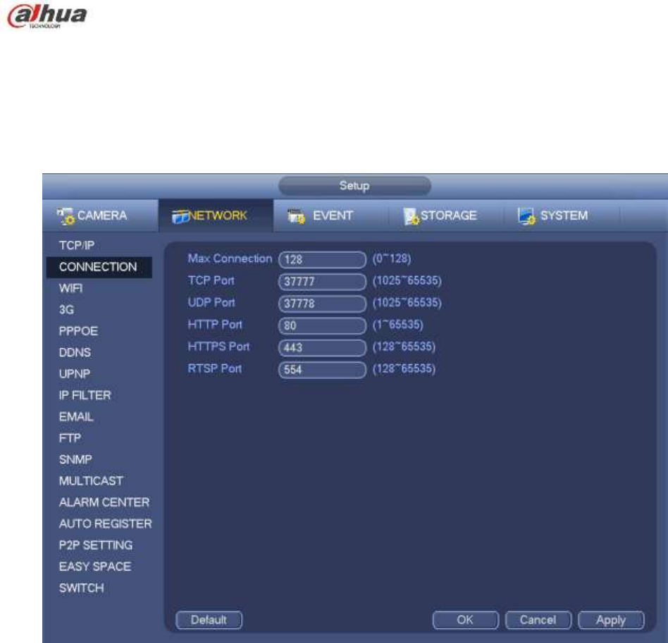
232
UDP port: Default value is 37778.
HTTP port: Default value is 80.
HTTPS port: Default value is 443.
RTSP port: Default value is 554.
Important: System needs to reboot after you changed and saved any setup of the above four ports.
Please make sure the port values here do not conflict.
Figure 4-122
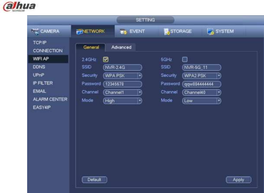
4.14.1.3 WIFI AP
Note
This function is for some series product only.
4.14.1.3.1 WIFI AP
The WIFI AP interface is shown as below. See Figure 4-123. Here you can set WIFI hotspot, so that the
network camera can use the hotspot to connect to the network.
2.4GHz/5GHz: Please check the box to enable the function.
SSID: It is to set SSID name. You can use this name to search the device.
Password: It is to set SSID password. You can use this password to connect to the network.
Security: Select authentication mode from the dropdown list.
Channel: Please select a channel from the dropdown list. The default setup is auto.
Mode: There three options: high/middle/low. Please select from the dropdown list.
233
Figure 4-123
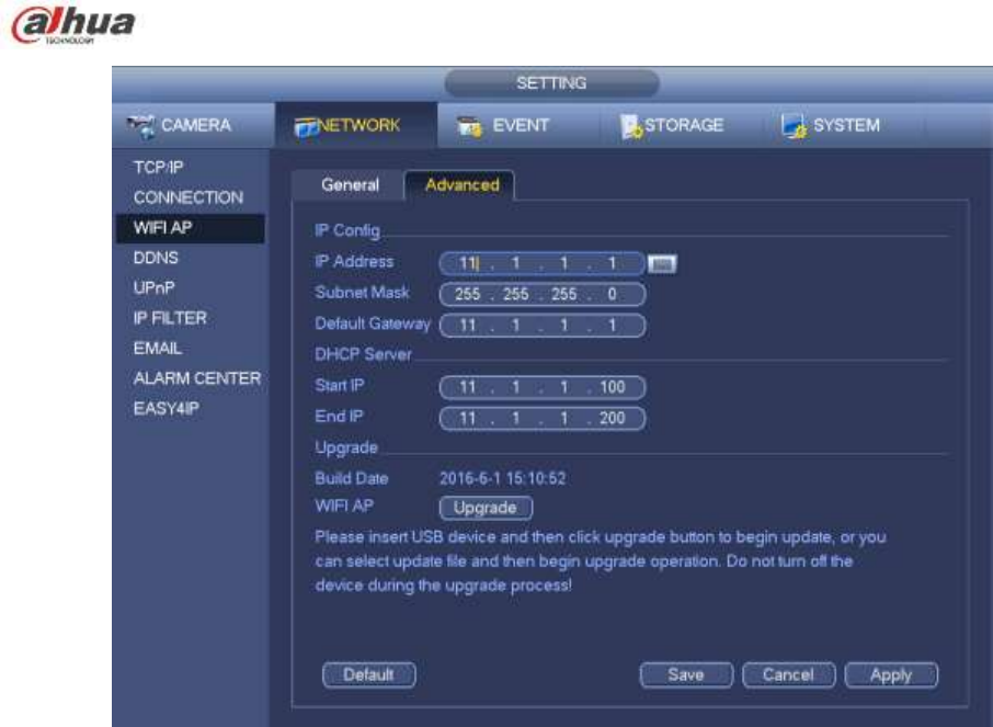
4.14.1.3.2 Advanced
Click Advanced, you can see an interface shown as below. See Figure 4-124.
IPv4 address: Input WIFI AP IP address.
IPv4 netmask: Input WIFI AP network mask.
IPv4 gateway: Input WIFI AP gateway.
Start IP/End IP: Input start IP and end IP of the network cameras. The NVR can allocate the IP
addresses in the range you specified here.
Upgrade: Click it to upgrade WIFI AP module.
234
Figure 4-124
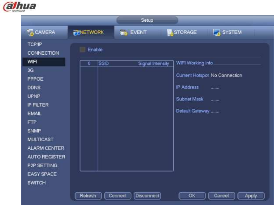
4.14.1.4 WIFI
The WIFI interface is shown as below. See Figure 4-125.
Enable: Check the box here to enable WIFI function.
Refresh: You can click it to search the hotspot list again. It can automatically add the information
such as the password if you have set it before.
Disconnect: Here you can click it to turn off the connection.
Connect: Here you can click it to connect to the hotspot. System needs to turn off current connection
and then connect to a new hotspot if there is connection of you selected one.
235
Figure 4-125
WIFI working status: Here you can view current connection status.
Please note:
After successful connection, you can see WIFI connection icon at the top right corner of the preview
interface.
When the hotspot verification type is WEP, system displays as AUTO since the device can not detect
its encryption type.
System does not support verification type WPA and WPA2. The display may become abnormal for
the verification type and encryption type.
After device successfully connected to the WIFI, you can view the hotspot name, IP address, subnet
mask, default gateway and etc. Right now system support TOTOLINK_N2200UP module.
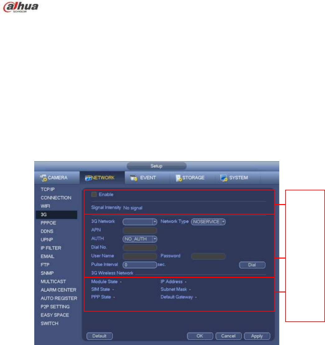
4.14.1.5 3G
3G setup interface is shown as below. See Figure 4-126.
Please refer to the following contents for the parameter information.
Pane 1: Display 3G signal intensity after you enabled 3G function.
Pane 2: Display 3G module configuration information after you enabled 3G function.
Pane 3: Display 3G module status information after you enabled 3G function.
It is to display current wireless network signal intensity such as EVDO, CDMA1x, WCDMA, WCDMA,
EDGE and etc.
3G module: It is to display current wireless network adapter name.
3G Enable/Disable: Check the box here to enable 3G module.
Network type: There are various network types for different 3G network modules. You can select
according to your requirements.
236
APN: It is the wireless connection server. It is to set you access the wireless network via which
method.
AUTH: It is the authentication mode. It supports PAP/CHAP.
Dial number: Please input 3G network dialup number you got from your ISP.
User name: It is the user name for you to login the 3G network.
Password: It is the password for you to login the 3G network.
Pulse interval: You can set dialup duration. Once you disable the extra stream, the connection time
begins. For example, if you input 5 seconds here, then 3G network connection period is 5 seconds.
The device automatically disconnect when time is up. If there is no extra stream, 3G network
connection is valid all the time. If the alive time is 0, then the 3G network connection is valid all
the time.
Dial: Here you can enable or disable 3G network connection/disconnection manually.
3G wireless network: Here is to display wireless network status, SIM card status, dial status. If the 3G
connection is OK, then you can see the device IP address the wireless network automatically
allocates.
Figure 4-126
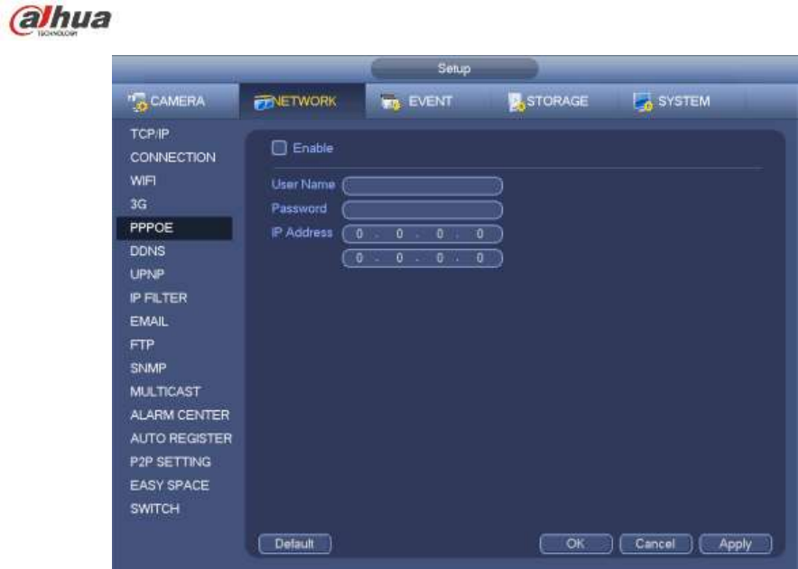
4.14.1.6 PPPoE
PPPoE interface is shown as in Figure 4-127.
Input ―PPPoE name‖ and ―PPPoE password‖ you get from your ISP (Internet service provider).
Click save button, you need to restart to activate your configuration.
After rebooting, NVR will connect to internet automatically. The IP in the PPPoE is the NVR dynamic
value. You can access this IP to visit the unit.
1
2
3
237
Figure 4-127
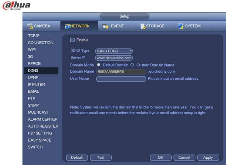
4.14.1.7 DDNS
DDNS setup interface is shown as in Figure 4-128.
You need a PC of fixed IP in the internet and there is the DDNS software running in this PC. In other
words, this PC is a DNS (domain name server).
In network DDNS, please select DDNS type and highlight enable item. And them please input your
PPPoE name you get from you IPS and server IP (PC with DDNS). Click save button and then reboot
system.
Click save button, system prompts for rebooting to get all setup activated.
After rebooting, open IE and input as below:
http://(DDNS server IP)/(virtual directory name)/webtest.htm
e.g.: http://10.6.2.85/NVR _DDNS/webtest.htm.)
Now you can open DDNSServer web search page.
238
Figure 4-128
Please note DDNS type includes: CN99 DDNS, NO-IP DDNS, Quick DDNS, Dyndns DDNS and sysdns
DDNS. All the DDNS can be valid at the same time, you can select as you requirement.
Private DDNS function shall work with special DDNS server and special Professional Surveillance
Software (PSS).
Dahua DDNS and Client-end Introduction
1) Background Introduction
Device IP is not fixed if you use ADSL to login the network. The DDNS function allows you to access the
NVR via the registered domain name. Besides the general DDNS, the Dahua DDNS works with the
device from the manufacturer so that it can add the extension function.
2) Function Introduction
The Dahua DDNS client has the same function as other DDNS client end. It realizes the bonding of the
domain name and the IP address. Right now, current DDNS server is for our own devices only. You need
to refresh the bonding relationship of the domain and the IP regularly. There is no user name, password
or the ID registration on the server. At the same time, each device has a default domain name (Generated
by MAC address) for your option. You can also use customized valid domain name (has not registered.).
3) Operation
Before you use Dahua DDNS, you need to enable this service and set proper server address, port value
and domain name.
Server address:www.dahuaddns.com
Port number:80
Domain name:There are two modes: Default domain name and customized domain name.
Except default domain name registration, you can also use customized domain name (You can input your
self-defined domain name.) After successful registration, you can use domain name to login installed of

239
the device IP.
User name: It is optional. You can input your commonly used email address.
Important
Do not register frequently. The interval between two registrations shall be more than 60 seconds. Too
many registration requests may result in server attack.
System may take back the domain name that is idle for one year. You can get a notification email
before the cancel operation if your email address setup is OK.
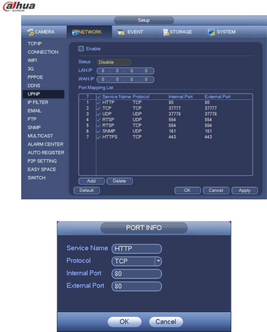
4.14.1.8 UPnP
The UPNP protocol is to establish a mapping relationship between the LAN and the WAN. Please input
the router IP address in the LAN in Figure 4-120. See Figure 4-129.
UPNP on/off :Turn on or off the UPNP function of the device.
Status: When the UPNP is offline, it shows as ―Unknown‖. When the UPNP works it shows
―Success‖
Router LAN IP: It is the router IP in the LAN.
WAN IP: It is the router IP in the WAN.
Port Mapping list: The port mapping list here is the one to one relationship with the router’s port
mapping setting.
List:
Service name:Defined by user.
Protocol: Protocol type
Internal port:Port that has been mapped in the router.
External port:Port that has been mapped locally.
Default: UPNP default port setting is the HTTP, TCP and UDP of the NVR.
Add to the list: Click it to add the mapping relationship.
Delete: Click it to remove one mapping item.
Double click one item; you can change the corresponding mapping information. See Figure 4-130.
Important:
When you are setting the router external port, please use 1024~5000 port. Do not use well-known
port 1~255 and the system port 256~1023 to avoid conflict.
For the TCP and UDP, please make sure the internal port and external port are the same to
guarantee the proper data transmission.
240
Figure 4-129
Figure 4-130
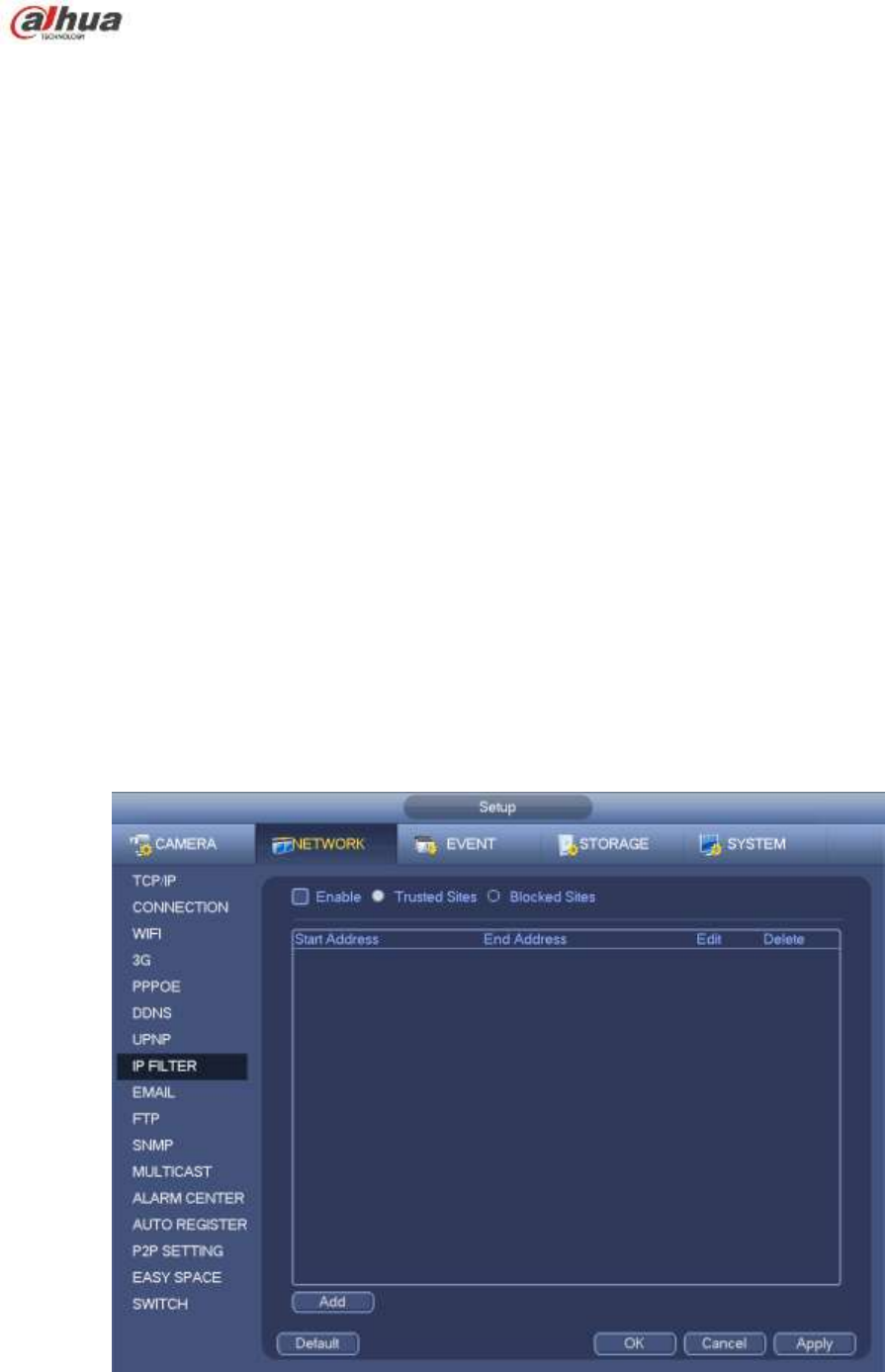
4.14.1.9 IP Filter
IP filter interface is shown as in Figure 4-131. You can add IP in the following list. The list supports max 64
IP addresses. System supports valid address of IPv4 and IPv6. Please note system needs to check the
validity of all IPv6 addresses and implement optimization.
After you enabled trusted sites function, only the IP listed below can access current NVR.
If you enable blocked sites function, the following listed IP addresses can not access current NVR.
Enable: Highlight the box here, you can check the trusted site function and blocked sites function.
You can not see these two modes if the Enable button is grey.
241
Type: You can select trusted site and blacklist from the dropdown list. You can view the IP address
on the following column.
Start address/end address: Select one type from the dropdown list, you can input IP address in the
start address and end address. Now you can click Add IP address or Add IP section to add.
a) For the newly added IP address, it is in enable status by default. Remove the √ before the item,
and then current item is not in the list.
b) System max supports 64 items.
c) Address column supports IPv4 or IPv6 format. If it is IPv6 address, system can optimize it. For
example, system can optimize aa:0000: 00: 00aa: 00aa: 00aa: 00aa: 00aa as aa:: aa: aa: aa: aa:
aa: aa.
d) System automatically removes space if there is any space before or after the newly added IP
address.
e) System only checks start address if you add IP address. System check start address and end
address if you add IP section and the end address shall be larger than the start address.
f) System may check newly added IP address exists or not. System does not add if input IP
address does not exist.
Delete: Click it to remove specified item.
Edit: Click it to edit start address and end address. See Figure 4-132. System can check the IP
address validity after the edit operation and implement IPv6 optimization.
Default: Click it to restore default setup. In this case, the trusted sites and blocked sites are both null.
Note:
If you enabled trusted sites, only the IP in the trusted sites list can access the device.
If you enabled blocked sites, the IP in the blocked sites can not access the device.
System supports add MAC address.
Figure 4-131

242
Figure 4-132
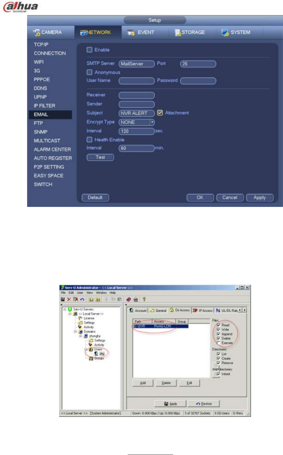
4.14.1.10 Email
The email interface is shown as below. See Figure 4-133.
SMTP server: Please input your email SMTP server IP here.
Port: Please input corresponding port value here.
User name: Please input the user name to login the sender email box.
Password: Please input the corresponding password here.
Sender: Please input sender email box here.
Title: Please input email subject here. System support English character and Arabic number. Max
32-digit.
Receiver: Please input receiver email address here. System max supports 3 email boxes. System
automatically filters same addresses if you input one receiver repeatedly.
SSL enable: System supports SSL encryption box.
Interval: The send interval ranges from 0 to 3600 seconds. 0 means there is no interval.
Health email enable: Please check the box here to enable this function. This function allows the
system to send out the test email to check the connection is OK or not.
Interval: Please check the above box to enable this function and then set the corresponding interval.
System can send out the email regularly as you set here. Click the Test button, you can see the
corresponding dialogue box to see the email connection is OK or not.
Please note system will not send out the email immediately when the alarm occurs. When the alarm,
motion detection or the abnormity event activates the email, system sends out the email according to the
interval you specified here. This function is very useful when there are too many emails activated by the
abnormity events, which may result in heavy load for the email server.
243
Figure 4-133
4.14.1.11 FTP
You need to download or buy FTP service tool (such as Ser-U FTP SERVER) to establish FTP service.
Please install Ser-U FTP SERVER first. From ―start‖ -> ―program‖ -> Serv-U FTP Server -> Serv-U
Administrator. Now you can set user password and FTP folder. Please note you need to grant write right
to FTP upload user. See Figure 4-134.
Figure 4-134
You can use a PC or FTP login tool to test setup is right or not.
For example, you can login user ZHY to H140H140H140HTUFTP://10.10.7.7UTH and then test it can modify or delete folder
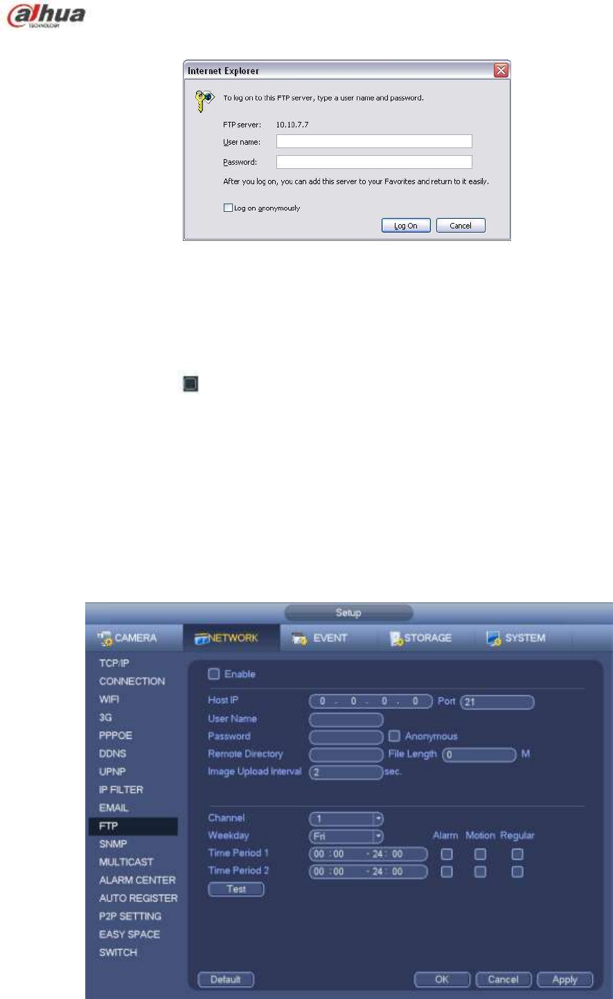
244
or not. See Figure 4-135.
Figure 4-135
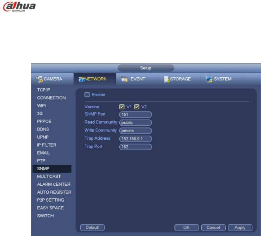
System also supports upload multiple NVRs to one FTP server. You can create multiple folders under this
FTP.
FTP interface is shown as in Figure 4-136.
Please highlight the icon in front of Enable to activate FTP function.
Here you can input FTP server address, port and remote directory. When remote directory is null, system
automatically create folders according to the IP, time and channel.
User name and password is the account information for you to login the FTP.
File length is upload file length. When setup is larger than the actual file length, system will upload the
whole file. When setup here is smaller than the actual file length, system only uploads the set length and
auto ignore the left section. When interval value is 0, system uploads all corresponding files.
After completed channel and weekday setup, you can set two periods for one each channel.
Click the Test button, you can see the corresponding dialogue box to see the FTP connection is OK or
not.
Figure 4-136
245
4.14.1.12 SNMP
SNMP is an abbreviation of Simple Network Management Protocol. It provides the basic network
management frame of the network management system. The SNMP widely used in many environments.
It is used in many network device, software and system.
You can set in the following interface. See Figure 4-137.
Figure 4-137
Please enable the SNMP function. Use the corresponding software tool (MIB Builder and MG-SOFT MIB
Browser. You still need two MIB file: BASE-SNMP-MIB, NVR-SNMP-MIB) to connect to the device. You
can get the device corresponding configuration information after successfully connection.
Please follow the steps listed below to configure.
In Figure 4-137, check the box to enable the SNMP function. Input the IP address of the PC than is
running the software in the Trap address. You can use default setup for the rest items.
Compile the above mentioned two MIB file via the software MIB Builder.
Run MG-SOFT MIB Browser to load the file from the previous step to the software.
Input the device IP you want to manage in the MG-SOFT MIB Browser. Please set the corresponding
version for your future reference.
Open the tree list on the MG-SOFT MIB Browser; you can get the device configuration. Here you can
see the device has how many video channels, audio channels, application version and etc.
Note
Port conflict occurs when SNMP port and Trap port are the same.
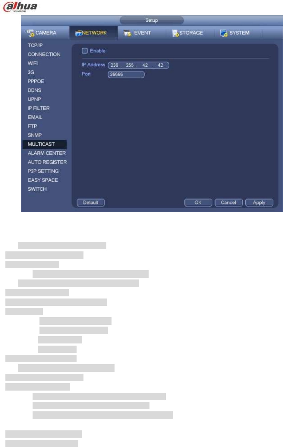
4.14.1.13 Multicast
Multicast setup interface is shown as in Figure 4-138.
246
Figure 4-138
Here you can set a multiple cast group. Please refer to the following sheet for detailed information.
IP multiple cast group address
-224.0.0.0-239.255.255.255
-―D‖ address space
The higher four-bit of the first byte=‖1110‖
Reserved local multiple cast group address
-224.0.0.0-224.0.0.255
-TTL=1 When sending out telegraph
-For example
224.0.0.1 All systems in the sub-net
224.0.0.2 All routers in the sub-net
224.0.0.4 DVMRP router
224.0.0.5 OSPF router
224.0.0.13 PIMv2 router
Administrative scoped addressees
-239.0.0.0-239.255.255.255
-Private address space
Like the single broadcast address of RFC1918
Can not be used in Internet transmission
Used for multiple cast broadcast in limited space.
Except the above mentioned addresses of special meaning, you can use other addresses. For example:
Multiple cast IP: 235.8.8.36
Multiple cast PORT: 3666.
247
After you logged in the Web, the Web can automatically get multiple cast address and add it to the
multiple cast groups. You can enable real-time monitor function to view the view.
Please note multiple cast function applies to special series only.
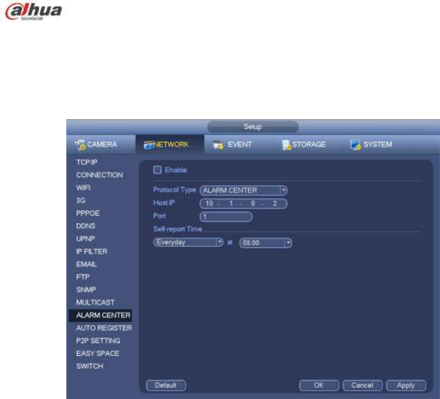
4.14.1.14 Alarm Centre
This interface is reserved for you to develop. See Figure 4-139.
Figure 4-139
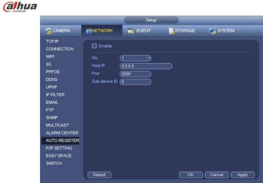
4.14.1.15 Auto register
This function allows the device to auto register to the proxy you specified. In this way, you can use the
client-end to access the NVR and etc via the proxy. Here the proxy has a switch function. In the network
service, device supports the server address of IPv4 or domain.
Please follow the steps listed below to use this function.
Please set proxy server address, port, and sub-device name at the device-end. Please enable the auto
register function, the device can auto register to the proxy server.
1) The setup interface is shown as in Figure 4-140.
Important
Do not input network default port such as TCP port number.
248
Figure 4-140
2) The proxy server software developed from the SDK. Please open the software and input the global
setup. Please make sure the auto connection port here is the same as the port you set in the previous
step.
3) Now you can add device. Please do not input default port number such as the TCP port in the mapping
port number. The device ID here shall be the same with the ID you input in Figure 4-140. Click Add button
to complete the setup.
4) Now you can boot up the proxy server. When you see the network status is Y, it means your
registration is OK. You can view the proxy server when the device is online.
Important
The server IP address can also be domain. But you need to register a domain name before you run proxy
device server.
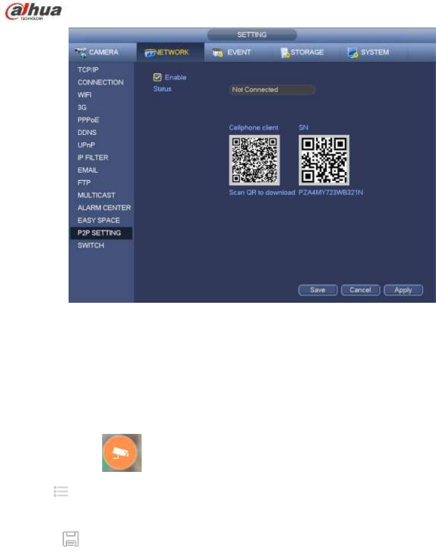
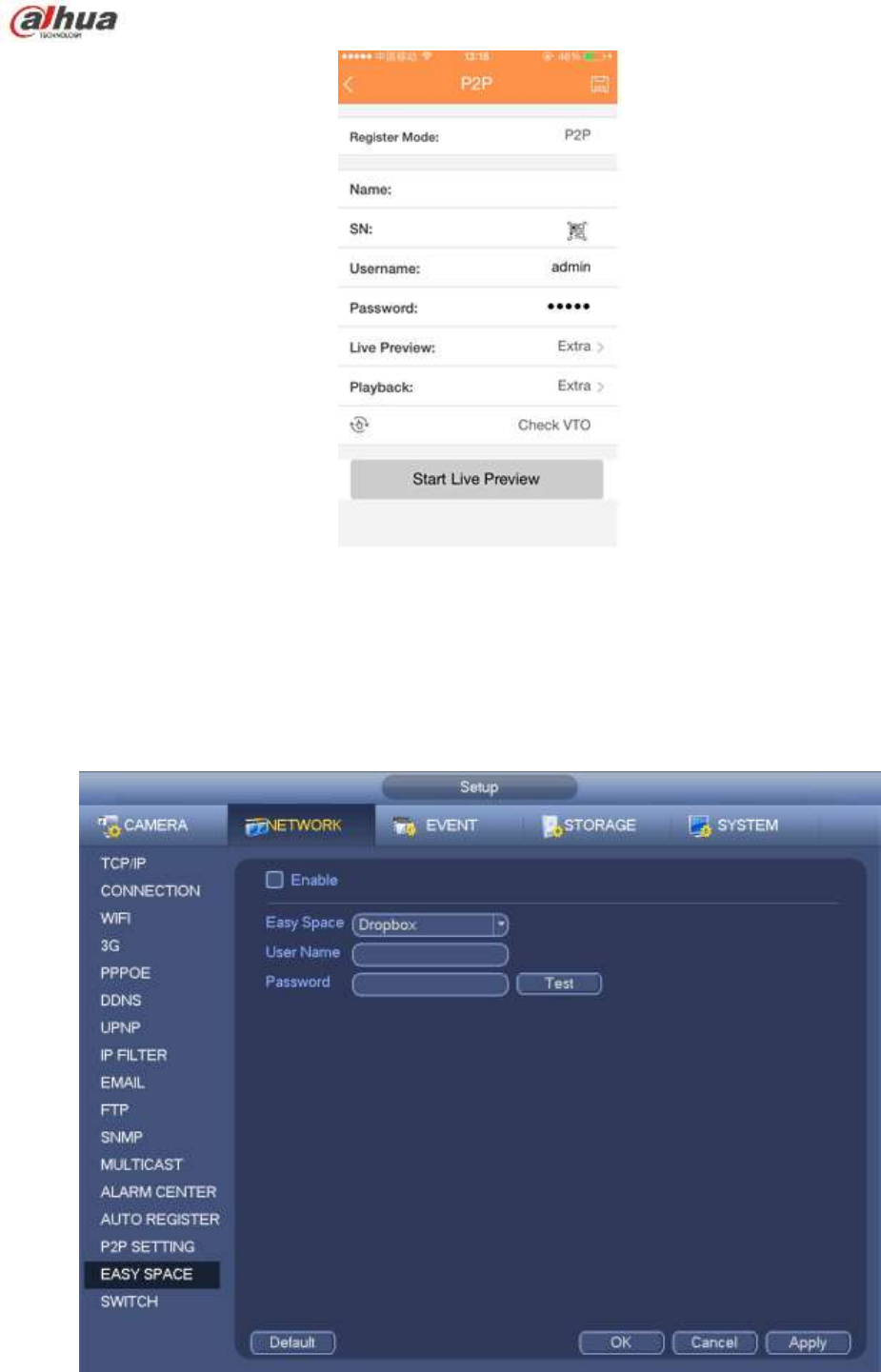
4.14.1.16 P2P
You can use your cell phone to scan the QR code and add it to the cell phone client.
Via the SN from scanning the QR code, you can access the device in the WAN. Please refer to the P2P
operation manual included in the resources CD.
From main menu->Setting->Network->P2P, you can go to the following interface, the P2P interface is
shown as in Figure 4-141.
249
Figure 4-141
Android:
Open Google Play app in your smart phone. Search gDMSS Lite or gDMSS Plus, download it and install.
iOS:
Open App Store app in your smart phone. Search iDMSS Lite or iDMSS Plus, download it and install.
Please follow the steps listed below.
Open App; tap to go to the Liv preview.
Tap at the top left corner, you can see the main menu.
Tap Device manager button, you can use several modes (P2P/DDNS/IP and etc) to add the device.
Click to save current setup. Tap Start Live preview to view all-channel video from the
connected device. See Figure 4-142.
250
Figure 4-142
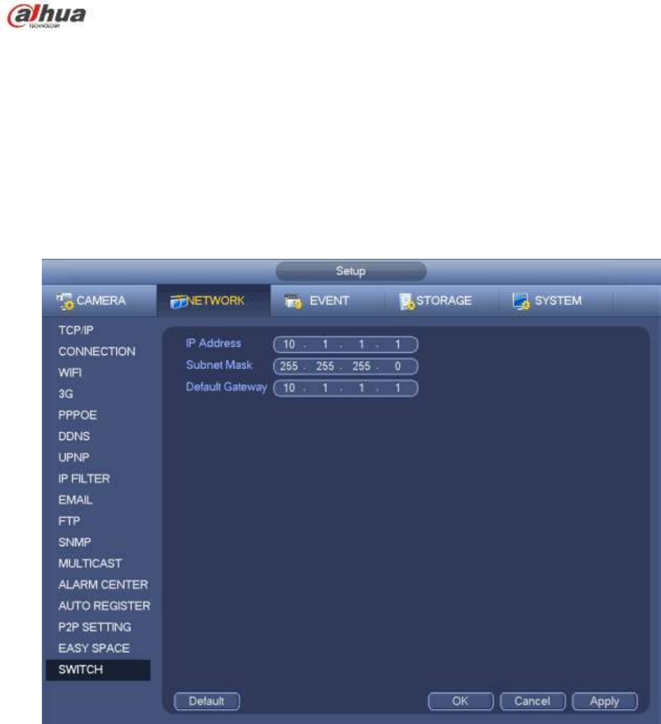
4.14.1.17 Easy Space
This function allows you to upload motion detect record or snapshot image to the dropbox and etc.
The easy space interface is shown as below. See Figure 4-143.
Please select the easy space address from the dropdown list and then input corresponding user name
and password.
Figure 4-143
251
Note:
The uploaded file is for sub stream only. Please go to record control interface (main
stream->setting->Storage->Record) and then select sub stream.
The easy space function uses upload bandwidth. Usually the recommended upload bandwidth shall
be more than 512kbps and please make sure the network is stable.
The easy space upload data adopts safe SSL encryption connection. Please enable 1-channel to
upload in case this function occupies too much CPU.
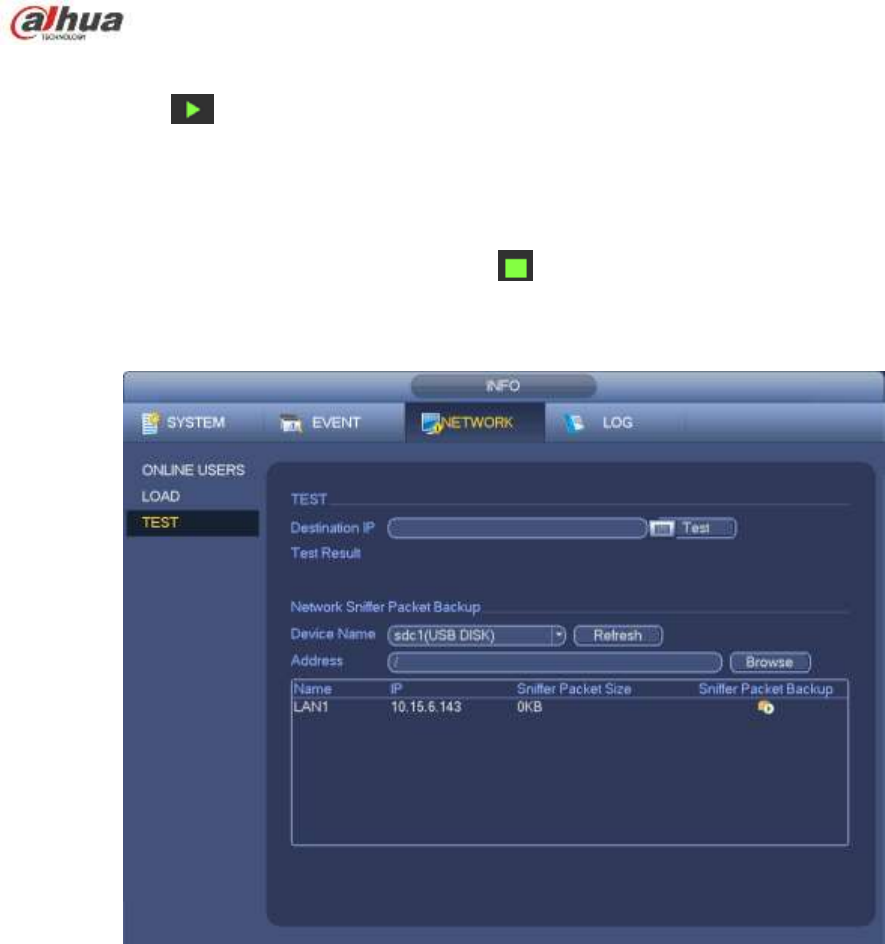
4.14.1.18 SWITCH
It is for you to set IP address, subnet mask, gateway and etc of the Switch. See Figure 4-144.
Figure 4-144
4.14.2 Network Test
In this interface, you can see network test and network load information.
4.14.2.1 Network Test
From main menu->Info-Network->Test, the network test interface is shown as in Figure 4-145.
Destination IP: Please input valid IPV4 address and domain name.
Test: Click it to test the connection with the destination IP address. The test results can display
average delay and packet loss rate and you can also view the network status as OK, bad, no
connection and etc.
Network Sniffer backup: Please insert USB2.0 device and click the Refresh button, you can view the
device on the following column. You can use the dropdown list to select peripheral device. Click
Browse button to select the snap path. The steps here are same as preview backup operation.
252
You can view all connected network adapter names (including Ethernet, PPPoE, WIFI, and 3G), you can
click the button on the right panel to begin Sniffer. Click the grey stop button to stop. Please note
system can not Sniffer several network adapters at the same time.
After Sniffer began, you can exit to implement corresponding network operation such as login WEB,
monitor. Please go back to Sniffer interface to click stop Sniffer. System can save the packets to the
specified path. The file is named after ―Network adapter name+time‖. You can use software such as
Wireshark to open the packets on the PC for the professional engineer to solve complicated problems.
Figure 4-145
4.14.2.2 Network Load
From main menu->Info-Network->Load, network load is shown as in Figure 4-146. Here you can view the
follow statistics of the device network adapter.
Here you can view information of all connected network adapters. The connection status is shown as
offline if connection is disconnected. Click one network adapter, you can view the flow statistics such as
send rate and receive rate at the top panel
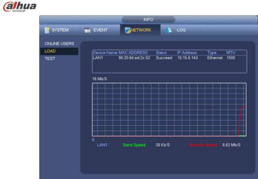
253
Figure 4-146
4.15 HDD Setup
Here you can view HDD information such as type, status, total capacity, record time and etc. The
operation includes format, resume from error, change HDD property (Read write, Read-only). Here you
can also set alarm and HDD storage position.
4.15.1 Format
a) From Mani-menu->Setting->Storage->HDD Manager, you can go to HDD management interface.
See Figure 4-147.
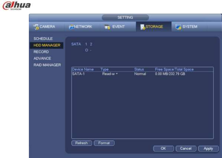
254
Figure 4-147
b) Select a HDD and then select format from the dropdown list. Click Execute button.
c) Click OK button to complete the setup. You can see system needs to restart to activate current setup.
4.15.2 HDD Information
Here is to list hard disk type, total space, free space, and status. See Figure 4-148.
○ means current HDD is normal.. - means there is no HDD.
If disk is damaged, system shows as ―?‖. Please remove the broken hard disk before you add a new one.
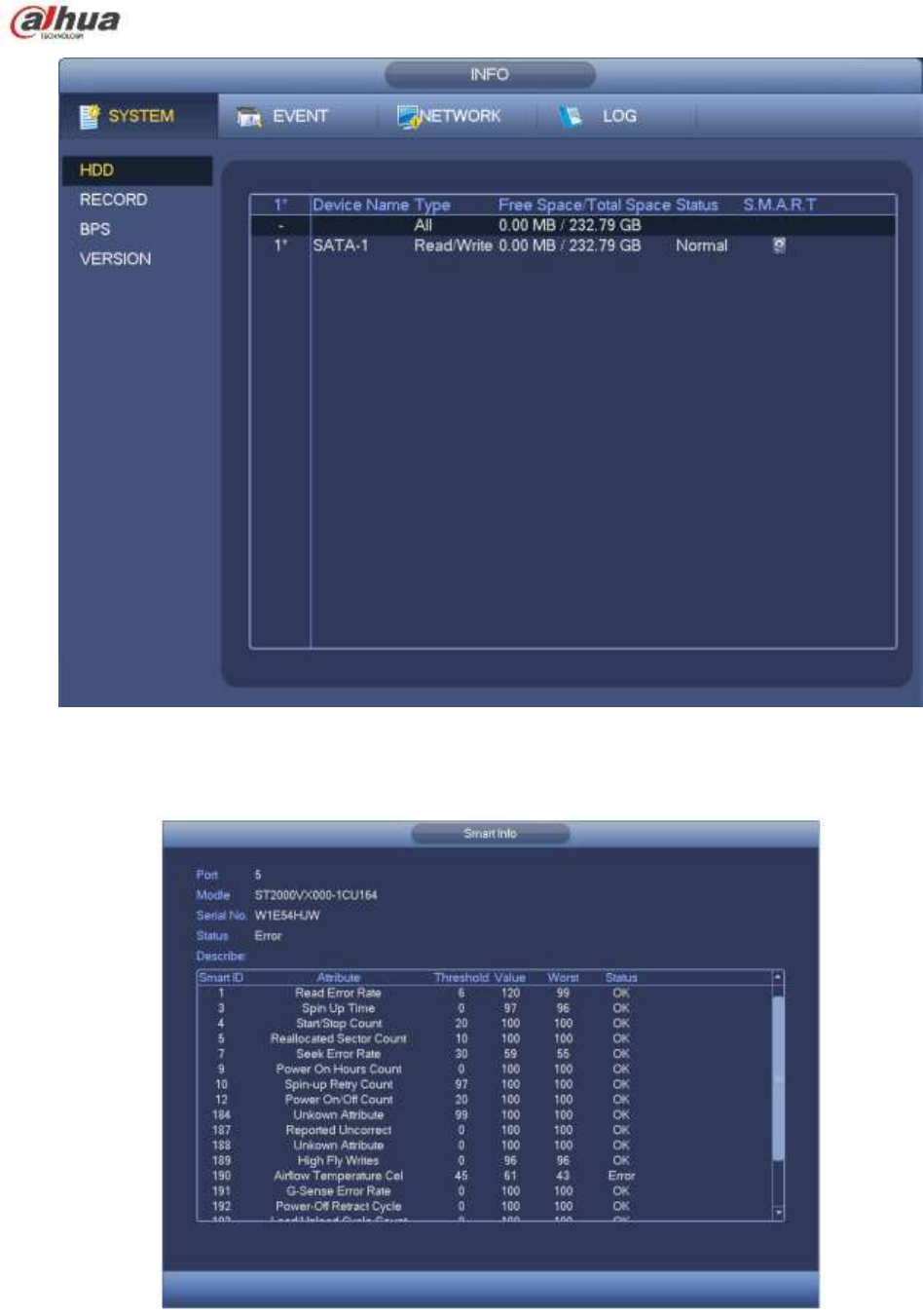

256
Parameter
Function
SATA
1 here means there is 1 HDD.
For different series product, the max HDD amount may vary,
When HDD is working properly, system is shown as O. . ―_‖ means there is
no HDD.
SN
You can view the HDD amount the device connected to;
﹡ means the second HDD is current working HDD.
Type
The corresponding HDD property.
Total space
The HDD total capacity.
Free space
The HDD free capacity.
Status
HDD can work properly or not.
Bad track
Display there is bad track or not.
Page up
Click it to view previous page.
Page down
Click it to view the next page.
View
recording time
Click it to view HDD record information (file start time and end time).
View HDD
type and
capability
Click it to view HDD property, status and etc,
4.15.3 Advanced
It is to set HDD group, and HDD group setup for main stream, sub stream and snapshot operation
Important
HDD group and quota mode can not be valid at the same time. System needs to restart once you
change the mode here.
The HDD group mode is shown as in Figure 4-150.
HDD: Here you can view the HDD amount the device can support.
Group: It lists the HDD Group number of current hard disk.
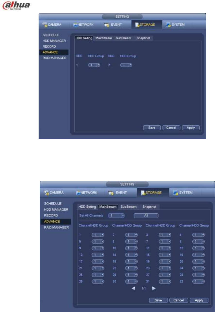
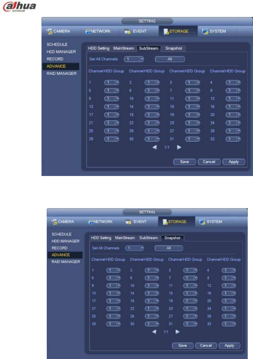
258
Figure 4-152
Figure 4-153
4.15.4 HDD Detect
Note
This function is for some series product only.
The HDD detect function is to detect HDD current status so that you can clearly understand the HDD
performance and replace the malfunction HDD.
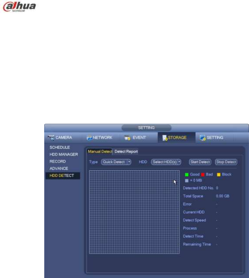
259
There are two detect types:
Quick detect is to detect via the universal system files. System can quickly complete the HDD
scan. If you want to use this function, please make sure the HDD is in use now. If the HDD is
removed from other device, please make sure the write-data once was full after it installed on
current device.
Global detect adopts Windows mode to scan. It may take a long time and may affect the HDD
that is recording.
4.15.4.1 Manual Detect
From main menu->Setting->Storage->HDD Detect->Manual Detect, the interface is shown as below. See
Figure 4-154.
Please select detect type and HDD. Click start detect to begin. You can view the corresponding detect
information.
Figure 4-154
4.15.4.2 Detect Report
After the detect operation, you can go to the detect report to view corresponding information.
From main menu->Setting->Storage->HDD Detect->Manual Detect, the interface is shown as below. See
Figure 4-155.
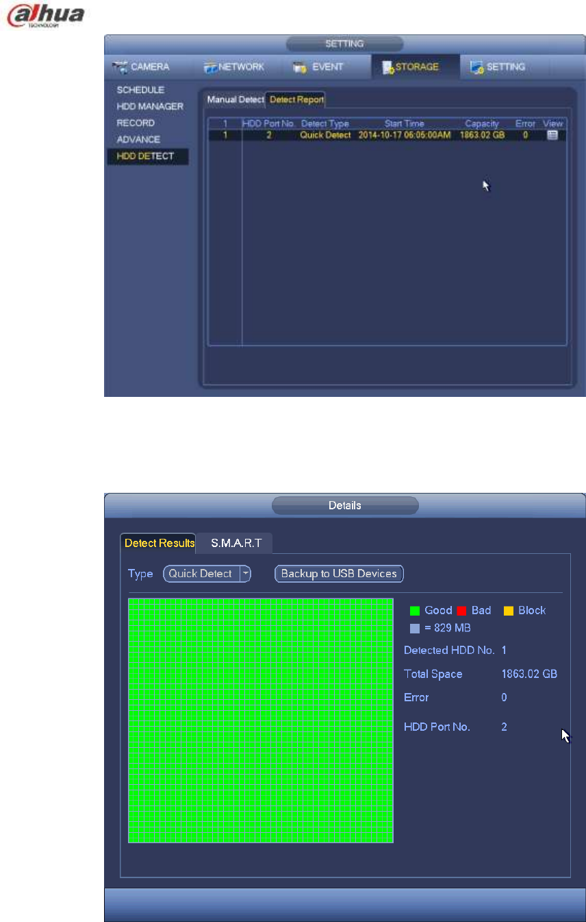
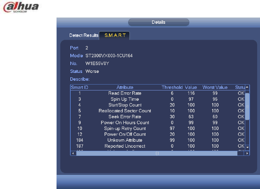
261
Figure 4-157
4.15.5 RAID Manager
Important
Please make sure your purchased product support the RAID function, otherwise you can not see
the following interface.
Right now, RAID supports Raid0, Raid1, Raid5, Raid6, and Raid10. Local hotspare supports Raid1,
Raid5, Raid6, and Raid10.
4.15.5.1 RAID Config
It is for you to manage RAID HDD. It can display RAID name, type, free space, total space, status and etc.
Here you can add/delete RAID HDD.
Click Add button to select RAID type and then select HDDs, click OK button to add. See Figure 4-158.
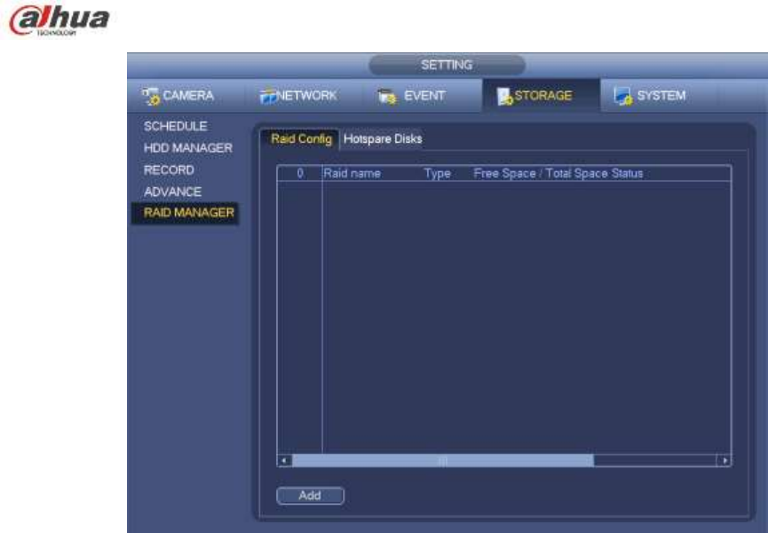
262
Figure 4-158
4.15.5.2 Hotspare disks
Click Hotspare disks tab name, you can add the hot spare HDD. See Figure 4-159. The type includes two
options:
Global: It is global hotspare disk. When any RAID becomes degrading, it can replace and build the
RAID.
Local: It is local hotspare disk. When the specified RAID becomes degrading, it can replace and build
the RAID.
Select a hot spare device and then click Delete button. Click Apply button to delete.
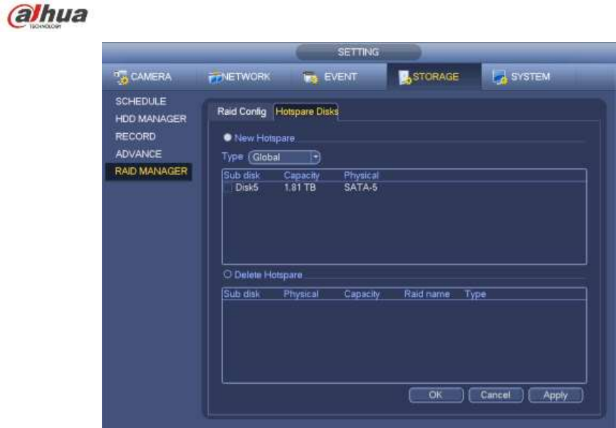
263
Figure 4-159
4.16 Basic Setups
Set NVR basic setup, device setup and other setups.
4.16.1 Device Setup
From Main menu->Setting->System->General, you can go to the general interface. See Figure 4-161.
Pack duration: Here is for you to specify record duration. The value ranges from 0 to 120 minutes.
Default value is 60 minutes.
Device ID: Please input a corresponding device name here.
Device No: When you are using one remote control (not included in the accessory bag) to control
several NVRs, you can give a name to each NVR for your management.
Language: System supports various languages: Chinese (simplified), Chinese (Traditional), English,
Italian, Japanese, French, Spanish (All languages listed here are optional. Slight difference maybe
found in various series.)
Video standard: There are two formats: NTSC and PAL.
HDD full: Here is for you to select working mode when hard disk is full. There are two options: stop
recording or rewrite. If current working HDD is overwritten or the current HDD is full while the next
HDD is no empty, then system stops recording, If the current HDD is full and then next HDD is not
empty, then system overwrites the previous files.
Pack duration: Here is for you to specify record duration. The value ranges from 1 to 120 minutes.
Default value is 60 minutes.
Realtime play: It is to set playback time you can view in the preview interface. The value ranges from
5 to 60 minutes.
Auto logout: Here is for you to set auto logout interval once login user remains inactive for a
specified time. Value ranges from 0 to 60 minutes.
Navigation bar: Check the box here, system displays the navigation bar on the interface.
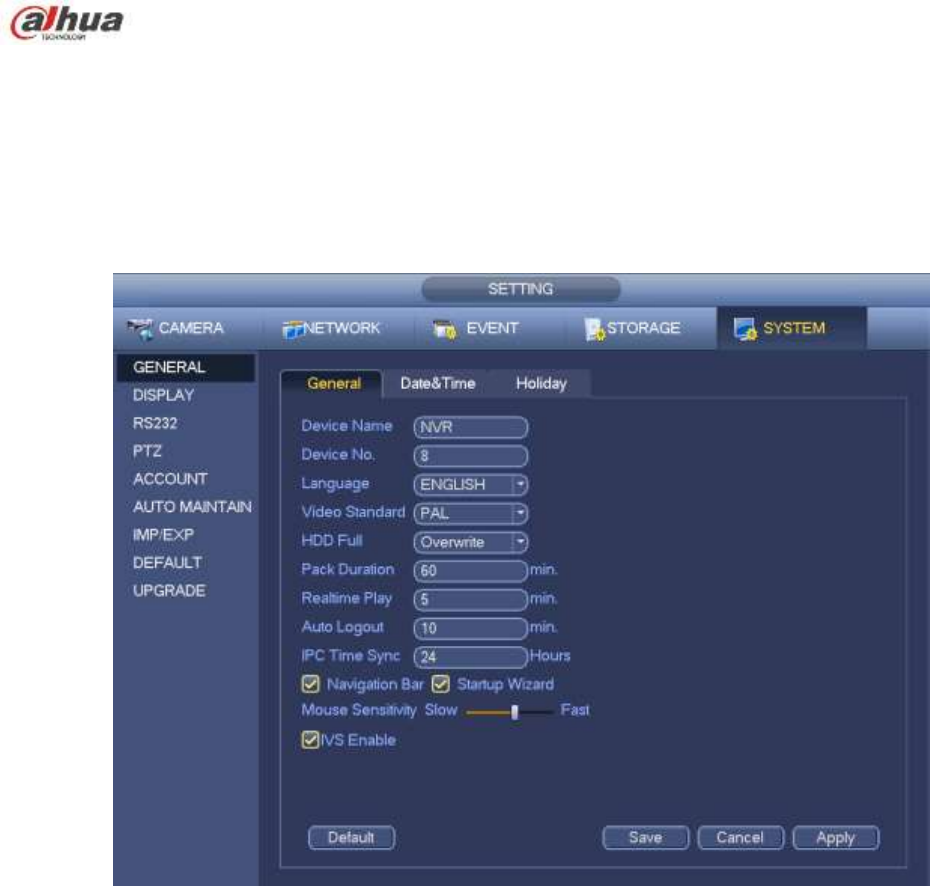
264
IPC Time Sync: You can input an interval here to synchronize the NVR time and IPC time.
Startup wizard: Once you check the box here, system will go to the startup wizard directly when the
system restarts the next time. Otherwise, it will go to the login interface.
Mouse sensitivity: You can set double click speed via dragging the slide bard. You can Click Default
button to restore default setup.
Enable IVS: Check the box to enable IVS function, system can display IVS rule on the preview
interface.
Figure 4-160
4.16.2 Data and Time
From Main menu->Setting->System->General, you can go to the general interface. See Figure 4-161.
System time: Here is for you to set system time
Date format: There are three types: YYYYY-MM-DD: MM-DD-YYYYY or DD-MM-YYYY.
Date separator: There are three denotations to separate date: dot, beeline and solidus.
DST: Here you can set DST time and date by week or by date. Please enable DST function and then
select setup mode. Please input start time and end time and click Save button.
Time format: There are two types: 24-hour mode or 12-hour mode.
NTP: It is to set NTP server, port and interval.
Note:
Since system time is very important, do not modify time casually unless there is a must!
Before your time modification, please stop record operation first!
After completing all the setups please click save button, system goes back to the previous menu.
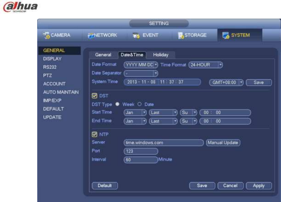
265
Figure 4-161
4.16.3 Holiday
Please refer to chapter 4.10.6 for detailed information.
4.17 Device Maintenance and Manager
4.17.1 System Info
4.17.1.1 Version
From main menu->Info->System->version, you can go to version interface.
Here is for you to view some version information. See Figure 4-162. Please note the following figure
for reference only.
Channel
Alarm in
Alarm out
System version
Build Date
Web
Serial number
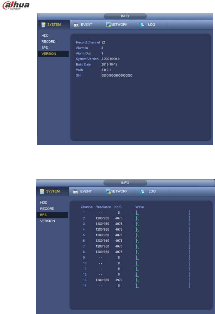
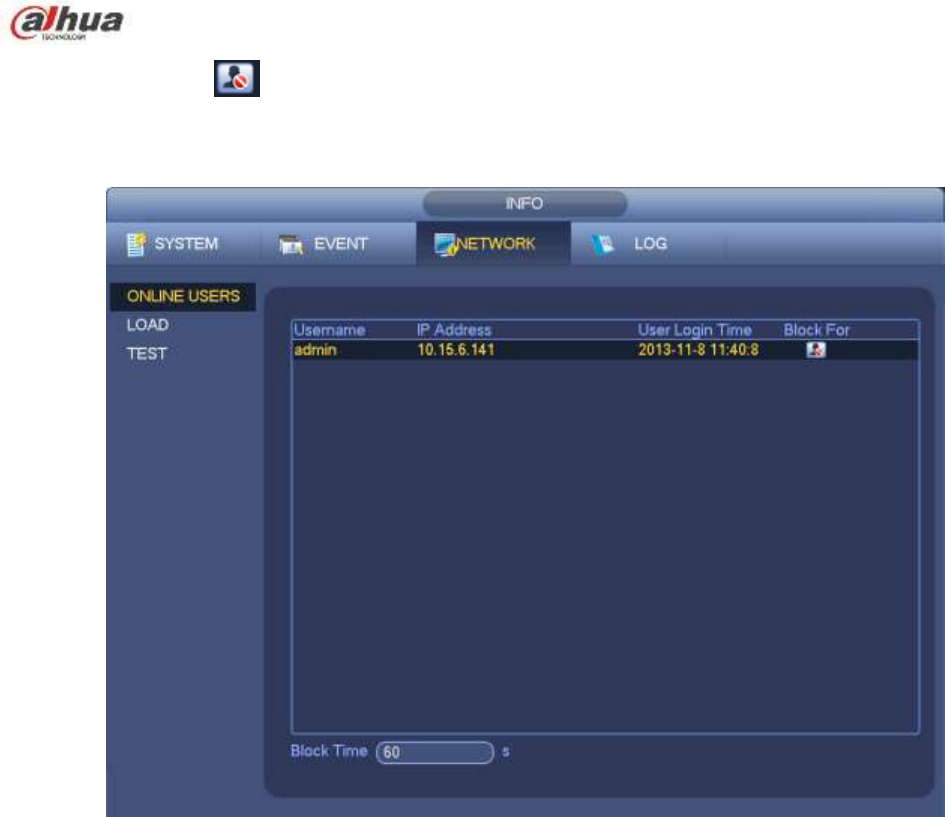
267
You can click button to disconnect or block one user if you have proper system right.
System detects there is any newly added or deleted user in each five seconds and refresh the list
automatically.
Figure 4-164
4.17.1.4 Remote Device Information
From main menu->info-Event, here you can view the channel status of the remote device, connection log
and etc. See Figure 4-165.
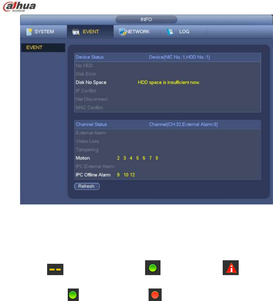
268
Figure 4-165
4.17.1.5 Remote
4.17.1.5.1 Device Status
Here you can view the IPC status of the corresponding channel such as motion detect, video loss,
tampering, alarm and etc. See Figure 4-166.
IPC status: : Front-end does not support. : Front-end supports. : There is alarm
event from current front-end.
Connection status: : Connection succeeded. : Connection failed.
Refresh: Click it to get latest front-end channel status.
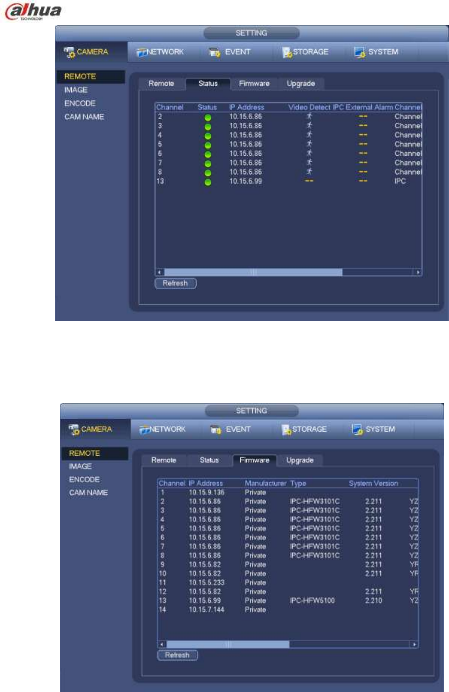
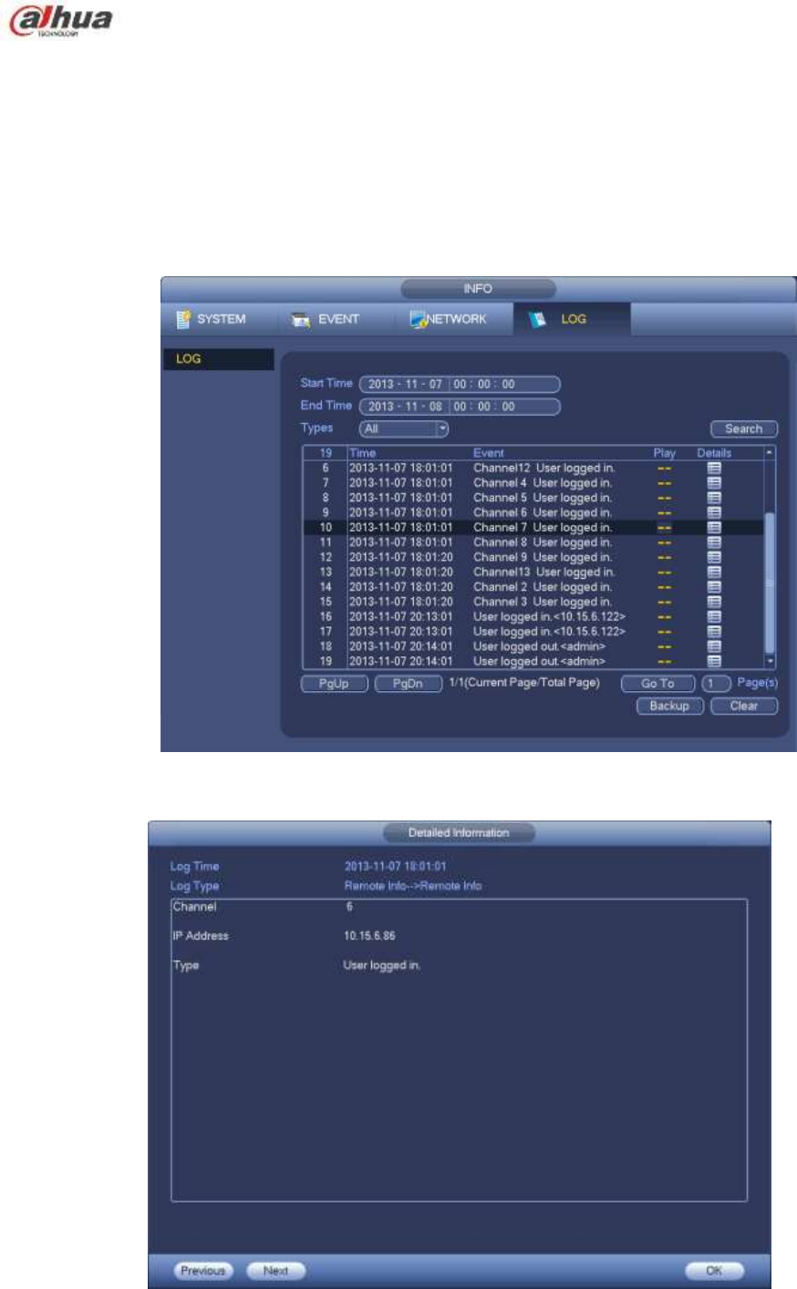
270
4.17.2 Log
From Main menu->Info->Log, you can go to the following interface. See Figure 4-168.
Start time/end time: Pleased select start time and end time, then click search button. You can view
the log files in a list. System max displays 100 logs in one page. It can max save 1024 log files.
Please use page up/down button on the interface or the front panel to view more.
Tips
Double click a log item to view its detailed information. See Figure 4-169.
Click PgUp/PgDn to view more logs.
Figure 4-168
Figure 4-169
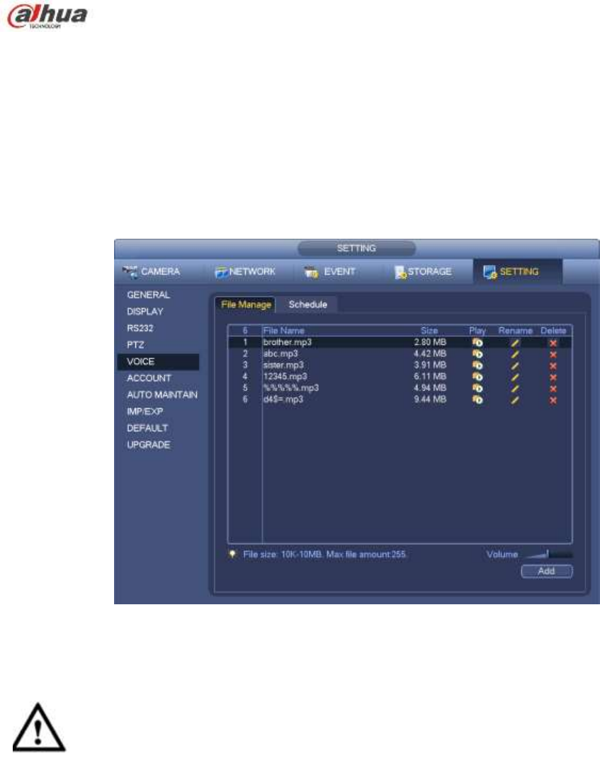
271
4.17.3 Voice
Note
This function is for some series product only.
The audio function is to manage audio files and set schedule play function. It is to realize audio broadcast
activation function.
4.17.3.1.1 File Manage
Here you can add audio file, listen to the audio file, or rename/delete audio file. Here you can also set
audio volume. See Figure 4-170.
Figure 4-170
Click Add button, you can add audio file and import the audio file via the USB device. The audio file
format shall be MP3 or PCM. See Figure 4-171.
Important
The audio file shall be saved on the USB device. You need to connect the USB device all the time;
otherwise, the audio link function may fail. So, if you want to use the audio trigger function,
please make sure the audio file is on the UBS device and the USB device has connected to the
NVR before the NVR boots up. You need to make sure the USB device connection is always there
if you want to manage and use the audio file function.
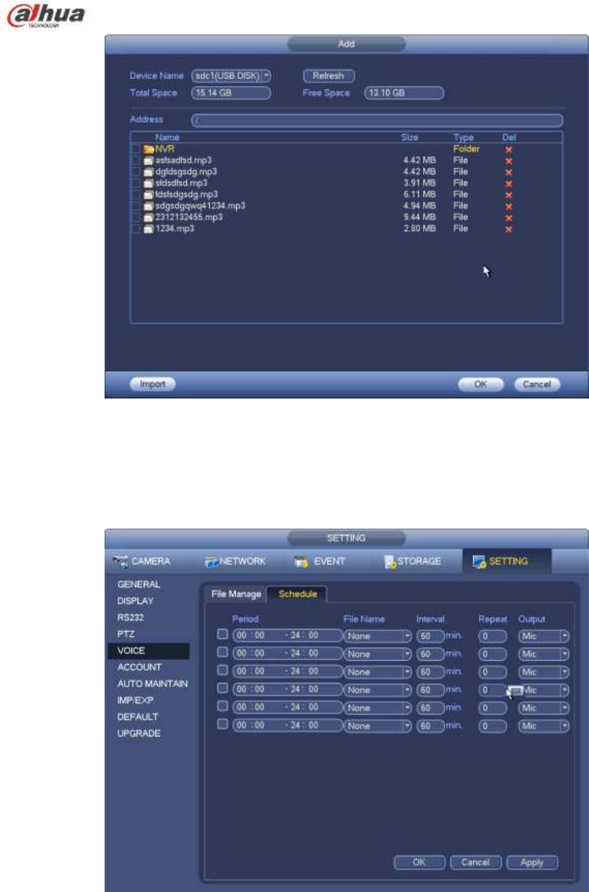
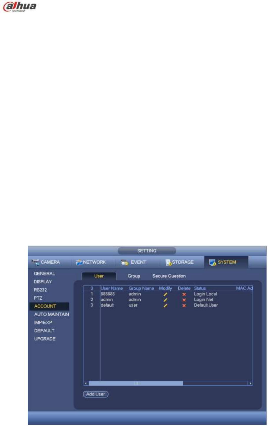
273
Modify user
Add group
Modify group
Modify password.
For account management please note:
For the user account name and the user group, the string max length is 6-byte. The backspace in
front of or at the back of the string is invalid. There can be backspace in the middle. The string
includes the valid character, letter, number, underline, subtraction sign, and dot.
The default user amount is 64 and the default group amount is 20. System account adopts two-level
management: group and user. No limit to group or user amount.
For group or user management, there are two levels: admin and user.
The user name and group name can consist of eight bytes. One name can only be used once. There
are three default users: admin/888888 and hidden user ―default‖.
Hidden user ―default‖ is for system interior use only and can not be deleted. When there is no login
user, hidden user ―default‖ automatically login. You can set some rights such as monitor for this user
so that you can view some channel view without login.
One user should belong to one group. User right can not exceed group right.
About reusable function: this function allows multiple users use the same account to login.
About user account and MAC. When you add a new user, you can input the MAC address of current
user. Only the user of the same MAC address can access the device remotely.(MAC address is for
the device of the same LAN.) If you leave MAC address item in blank when you add a new user, the
user of any MAC address can access the device remotely. You can set or change MAC address
when you add or modify a user. The MAC address function is also valid for PSS login. Please note
current function does not support IPV6.
After all the setups please click save button, system goes back to the previous menu.
Figure 4-173
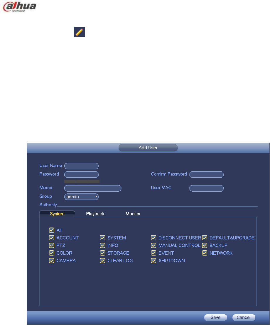
274
4.17.4.1.1 Add User
Click modify user button in Figure 4-173 , the interface is shown as in Figure 4-174.
Please input the user name, password, select the group it belongs to from the dropdown list.
Then you can check the corresponding rights for current user.
For convenient user management, usually we recommend the general user right is lower than the admin
account.
Username: admin. Password: admin. (administrator, local and network)
Username: 888888. Password: 888888. (administrator, local only)
Username: default. Password: default (hidden user). Hidden user ―default‖ is for system interior use
only and can not be deleted. When there is no login user, hidden user ―default‖ automatically login.
You can set some rights such as monitor for this user so that you can view some channels without
login.
Figure 4-174
When you create a new user, you can input the corresponding MAC address of current user. If you leave
this item in blank, any MAC address user can share this user account to login. Please note system needs
to check the validity of MAC. Only the 12-digit 0-f format address can pass the validity verification.
System only saves small character even you input capitalized one. You can see the corresponding
prompt if there is any illegal input.
Click the Set button after the period, you can set valid period to use current account. See Figure 4-175.
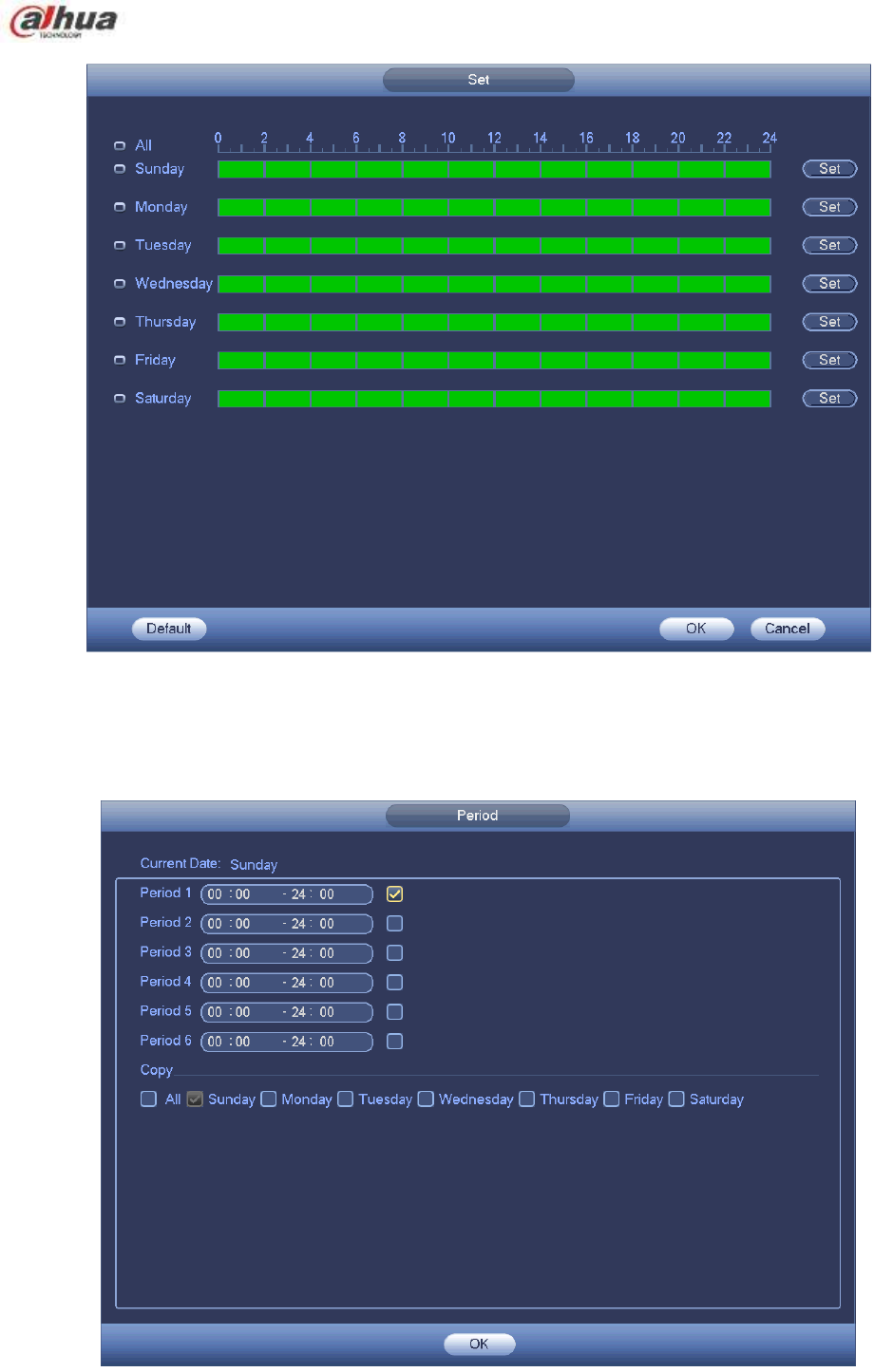
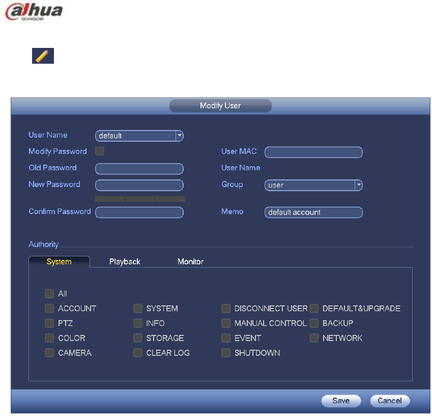
276
4.17.4.1.2 Modify user
Click , you can go to the following interface to change user information. See Figure 4-177.
For admin, 888888, and default (hidden user), you can not change period setup.
Figure 4-177
4.17.4.1.3 Change Password
In Figure 4-177, check the Modify password box, you can change password. Please input old password,
and then input new password twice to confirm.
The password can contain 32-byte and the space at the begin or at the end of the password are null. It
can contain in the middle of the password. For the user of account right, it can change the password of
other users.
4.17.4.1.4 Add/Modify Group
In Figure 4-173, click Group button, you can see the following interface. See Figure 4-178.
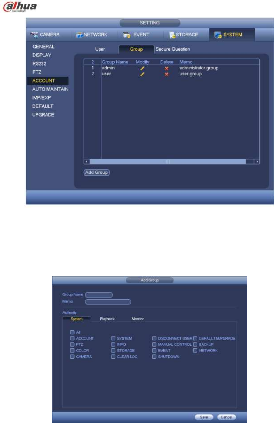
277
Figure 4-178
Click add group button in Figure 4-178 , the interface is shown as below. See Figure 4-179.
Here you can input group name and then input some memo information if necessary.
There are total 98 rights such as control panel, shut down, real-time monitor, playback, record, record file
backup, PTZ, user account, system information view, alarm input/output setup, system setup, log view,
clear log, upgrade system, control device and etc.
Figure 4-179
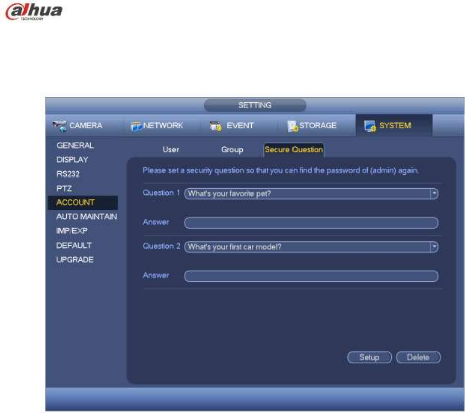
278
4.17.4.1.5 Security Question
The security question is shown as below. See Figure 4-180.
Here you can change security questions.
Figure 4-180
4.17.5 Update
4.17.5.1 Local Update
From Mani menu->Setting->Info->Update, you can go to the following interface. See Figure 4-181.
a) Insert USB device that contain the upgrade file.
b) Click Start button and then select the .bin file.
c) You can see the corresponding dialogue box after the update process is complete.
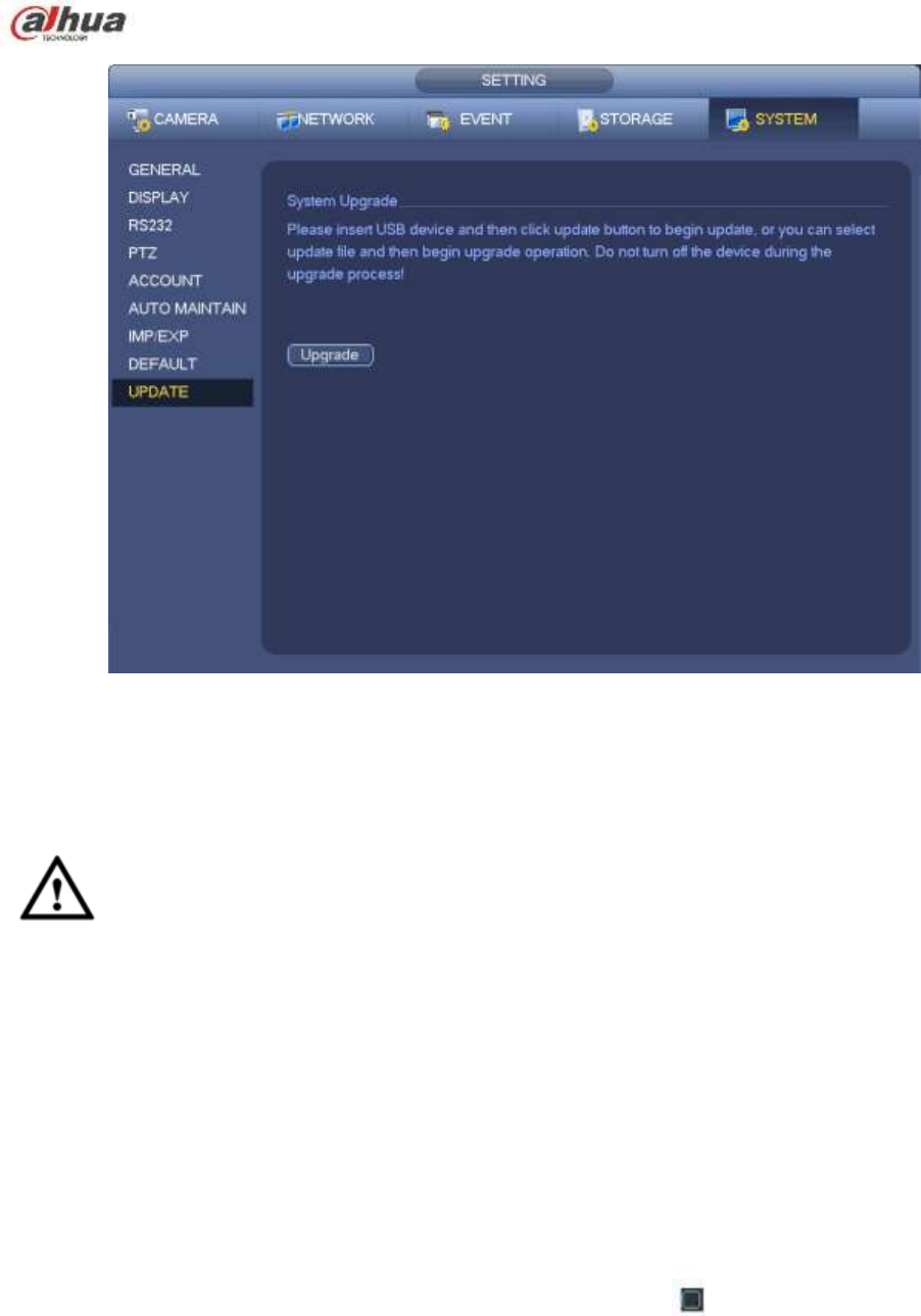
279
Figure 4-181
4.17.5.2 Uboot
When device is booting up, it can auto detect the USB device and the update file on it. It can auto update
once there is proper upgrade file.
Important
USB device root directory shall have ―u-boot.bin.img‖ and ―update.img‖ files. USB device shall be
FAT32 mode.
For 4X series product, it only updates ―update.img‖. The ―update.img‖ shall be renamed as
―recovery.img‖ and is saved on the root directory.
USB device shall be on the USB 2.0 port, otherwise device can not detect or update.
4.17.6 Default
You can restore factory default setup to fix some problems when the device is running slowly.
Configuration error occurred.
From Main menu->Setting->System->Default, you can go to the default interface. See Figure 4-182.
Click default icon, system pops up a dialogue box. You can highlight to restore factory default setup.
All
Camera
Network
Event
Storage
System
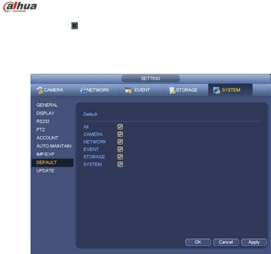
280
Please highlight icon to select the corresponding function.
After all the setups please click OK button, system goes back to the previous menu.
Warning!
After you use default function, some your customized setup may lose forever! Please think twice before
you begin the operation!
Figure 4-182
4.17.7 RS232
From Main menu->Setting->System->RS232, RS232 interface is shown as below. There are five items.
See Figure 4-183.
Function: There are various devices for you to select. Console is for you to use the COM or mini-end
software to upgrade or debug the program. The control keyboard is for you to control the device via
the special keyboard. Transparent COM (adapter) is to connect to the PC to transfer data directly.
Protocol COM is for card overlay function. Network keyboard is for you to use the special keyboard
to control the device. PTZ matrix is to connect to the peripheral matrix control.
Baud rate: You can select proper baud rate.
Data bit: You can select proper data bit. The value ranges from 5 to 8.
Stop bit: There are three values: 1/1.5/2.
Parity: there are five choices: none/odd/even/space mark.
System default setup is:
Function: Console
Baud rate:115200
Data bit:8
Stop bit:1
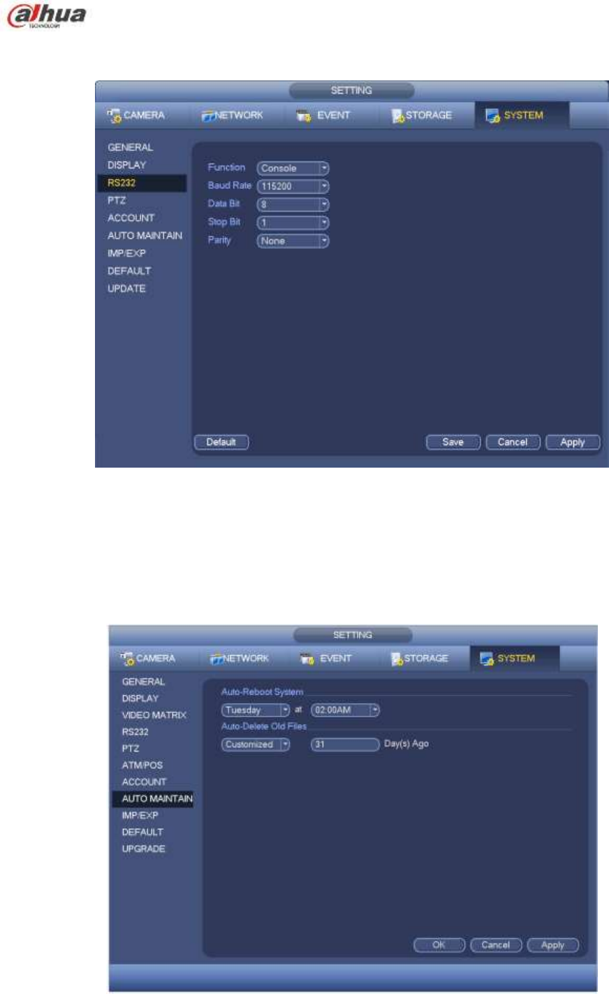
281
Parity: None
After completing all the setups please click save button, system goes back to the previous menu.
Figure 4-183
4.17.8 Auto Maintain
Here you can set auto-reboot time and auto-delete old files setup. You can set to delete the files for the
specified days. See Figure 4-184.
You can select proper setup from dropdown list.
After all the setups please click save button, system goes back to the previous menu.
Figure 4-184
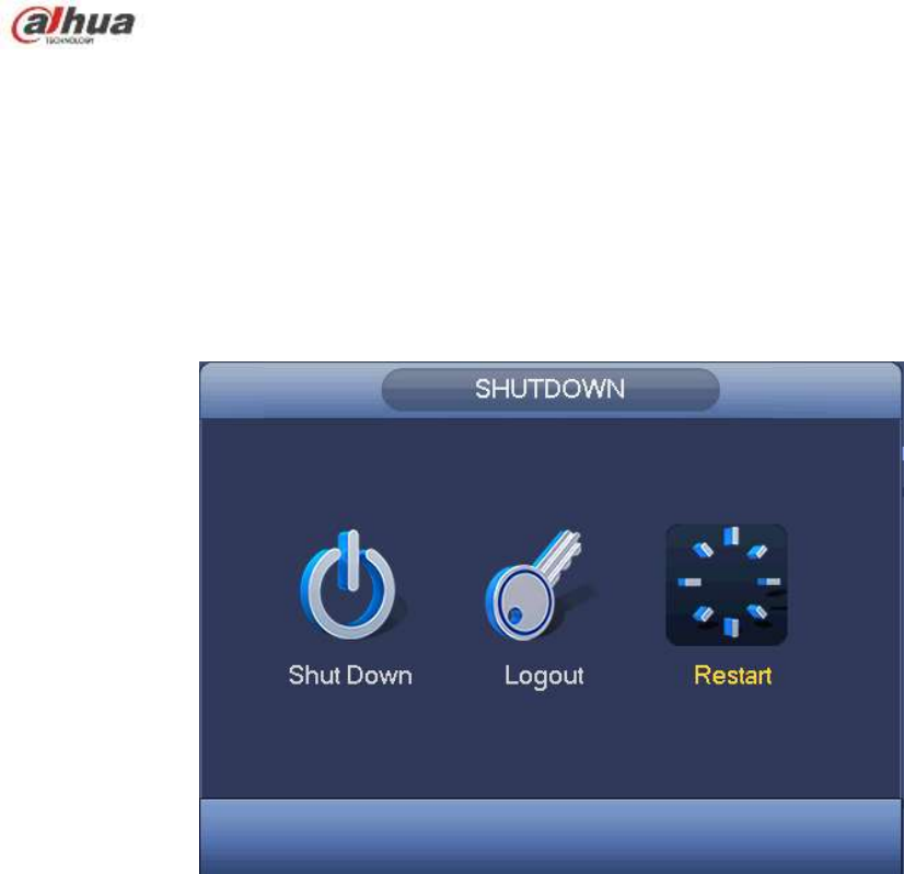
282
4.17.9 Logout /Shutdown/Restart
From Mani menu->Operation->Shutdown, you can see an interface shown as in Figure 4-185.
Shutdown: System shuts down and turns off power.
Logout: Log out menu. You need to input password when you login the next time.
Restart: reboot device.
If you shut down the device, there is a process bar for your reference, system waits for 3 seconds and
then shut down (You can not cancel).
Please note, sometimes you need to input the proper password to shut down the device.
Figure 4-185

283
5 Web Operation
5.1 General Introduction
The device web provides channel monitor menu tree, search, alarm setup, system setup, PTZ control and
monitor window and etc.
Important
The following operation is based on 32-channel series device.
5.1.1 Preparation
Before log in, please make sure:
Network connection is right
NVR and PC network setup is right. Please refer to network setup(main
menu->setting->network)
Use order ping ***.***.***.***(* NVR IP address) to check connection is OK or not. Usually the return
TTL value should be less than 255.
Open the IE and then input NVR IP address.
System can automatically download latest web control and the new version can overwrite the
previous one.
About PoE address setup, operation and allocation.
1) Insert PoE
After you insert PoE, device may try to set a corresponding IP address of the Switch network adapter.
First, system tries to set via arp ping. It then uses DHCP if it finds the DHCP is enabled. After successfully
set IP address, system may use Switch to send out broadcast, system considers the connection is OK
when there is any response. Now system is trying to login the newly found IPC. Now please check the
interface, you can see the corresponding digital channel is active now. You can see a small PoE icon at
the top left corner. You can see the PoE channel, PoE port information and etc from the connection list of
the registration interface (Chapter 5.8.1.1). For the IP search list, you need to click the IP search to
display or refresh.
2) Remove PoE
After you removed PoE, you can see the corresponding digital channel becomes idle (disable). On the
registration interface, it is removed from the connected list. For the IP search list, you need to click the IP
search to refresh.
3) After you insert PoE, system follows the principles listed below to map channel.
a) If it is your first time to insert PoE, system can map it to the first idle channel. After map, the
channel can memorize the MAC address of the IPC. It is a <Channel>---<IPC mac> map. If
current channel does not connect to other device, system can memorize current MAC
address, otherwise it can refresh to the newly added device and memorize the <PoE
port>---<Channel>.
b) If it is your second time to insert the PoE, system can check the saved MAC address
according to <Channel>---<IPC mac> map to make sure current IPC has connected or not.
If system finds the previous information and the channel is idle, system can map it to the
previously used channel. Otherwise system goes to the next step.
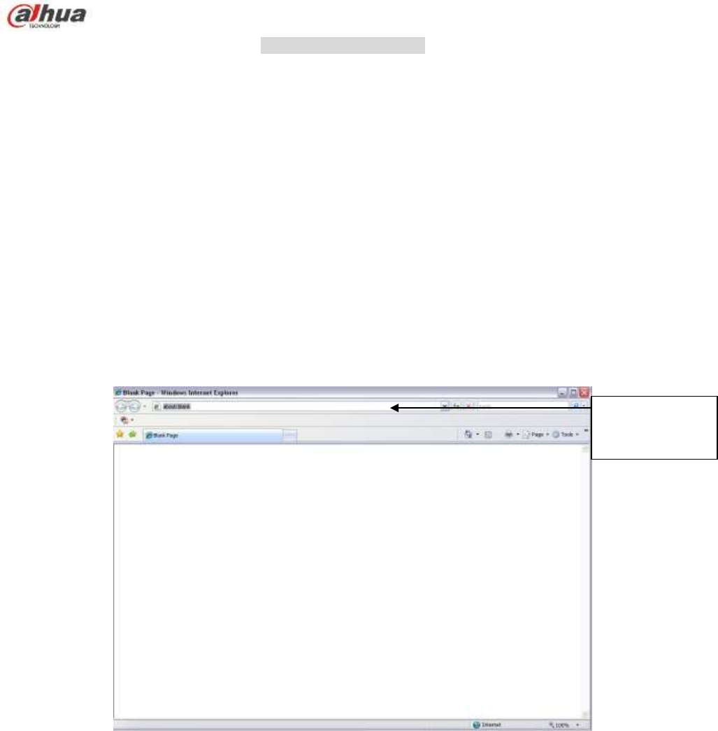
284
c) Thirdly, according to the <PoE port>---<Channel> map, system can know the previous
mapping channel of current PoE port. System can select current channel if it is free.
Otherwise, it goes to the next step:
d) Fourthly, system goes to find the first idle channel it can get.
Generally speaking, once you insert PoE, system follow the steps listed above to find the channel
available.
4) When you insert PoE, all channels are in use now.
System can pop up a dialogue box for you to select a channel to overwrite. The title of the pop-up
interface is the name of the current operation PoE port. In this interface, All PoE channel become grey
and can not select.
5.1.2 Log in
Open the IE and then input the NVR IP address in the address column.
For example, if your NVR IP address is 192.168.1.108, then please input http:// 192.168.1.108 in IE
address column. See Figure 5-1.
Figure 5-1
System pops up warning information to ask you whether install Web plug-in or not. Please click yes
button.
If you can’t download the ActiveX file, please modify your settings as follows. See Figure 5-2.
Input IP
address here.
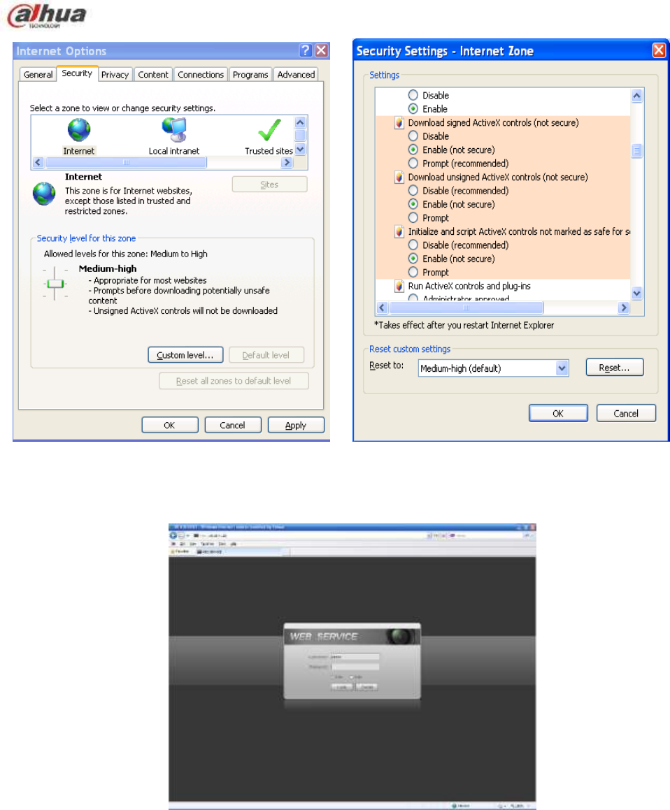
285
Figure 5-2
After installation, the interface is shown as below. See Figure 5-3.
Figure 5-3
Please input your user name and password.
Default factory name is admin and password is admin.
Note: For security reasons, please modify your password after you first login.
5.2 LAN Mode
For the LAN mode, after you logged in, you can see the main window. See Figure 5-9.
This main window can be divided into the following sections.
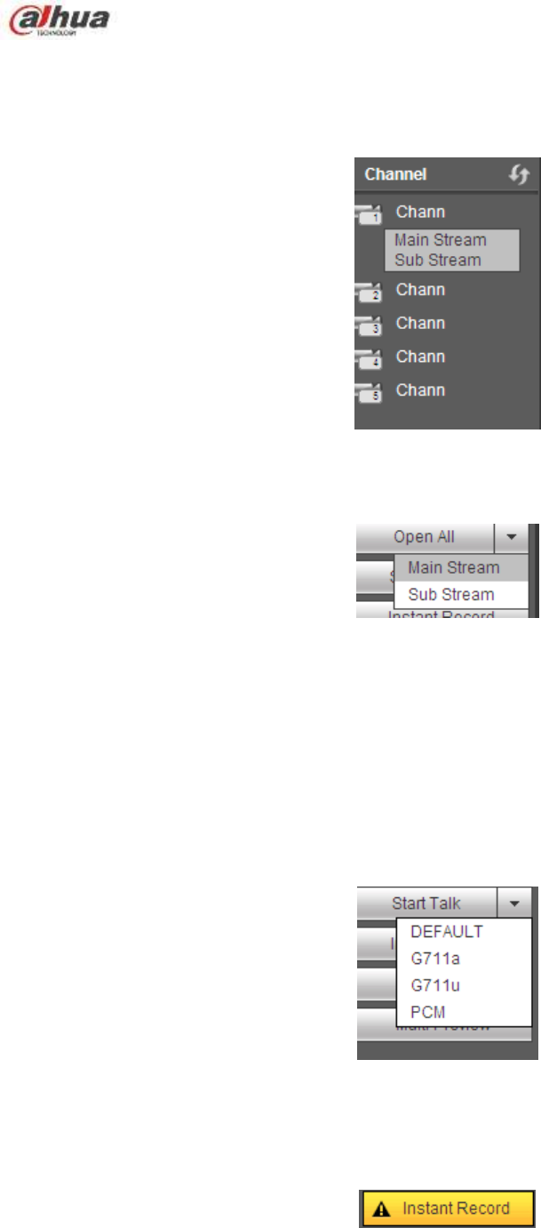
286
Section 1: there are six function buttons: Live(chapter 0), setup (chapter 5.8), info (Chapter 5.9),
playback (chapter 5.10), alarm (chapter 5.11), and logout (chapter 5.12).
Section 2: There are monitor channels successfully connected to the NVR.
Please refer to Figure 5-4 for main stream and extra stream switch information.
Figure 5-4
Section 3: Open all. Open all button is to enable/disable all-channel real-time monitor. Here you can
select main stream/sub stream too. See Figure 5-5.
Figure 5-5
Section 4: Start Talk button.
You can click this button to enable audio talk. Click 【▼】 to select bidirectional talk mode. There are four
options: DEFAULT,G711a,G711u and PCM. See Figure 5-6.
After you enable the bidirectional talk, the Start talk button becomes End Talk button and it becomes
yellow. Please note, if audio input port from the device to the client-end is using the first channel audio
input port. During the bidirectional talk process, system will not encode the audio data from the 1-channel.
Figure 5-6
Section 5: Instant record button. Click it, the button becomes yellow and system begins manual
record. See Figure 5-7. Click it again, system restores previous record mode.
Figure 5-7
Section 6: Local play button.
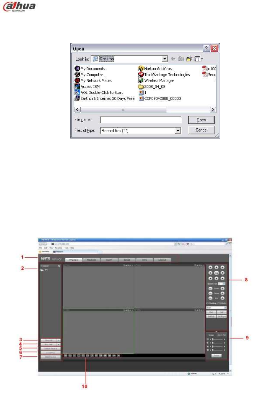
287
The Web can playback the saved (Extension name is dav) files in the PC-end.
Click local play button, system pops up the following interface for you to select local play file. See Figure
5-8.
Figure 5-8
Section 7:Zero-channel encoding. Please refer to chapter 5.6 for detailed information.
Section 8: PTZ operation panel. Please refer to chapter 5.4 for detailed information.
Section 9: Image setup and alarm setup. Please refer to chapter 5.5 for detailed information.
Section 10: From the left to the right ,you can see video quality/fluency/ full
screen/1-window/4-window/6-window/8-window/9-window/13-window/16-window/20-window/25-win
dow/36-window.. You can set video fluency and real-time feature priority.
Figure 5-9
5.3 Real-time Monitor
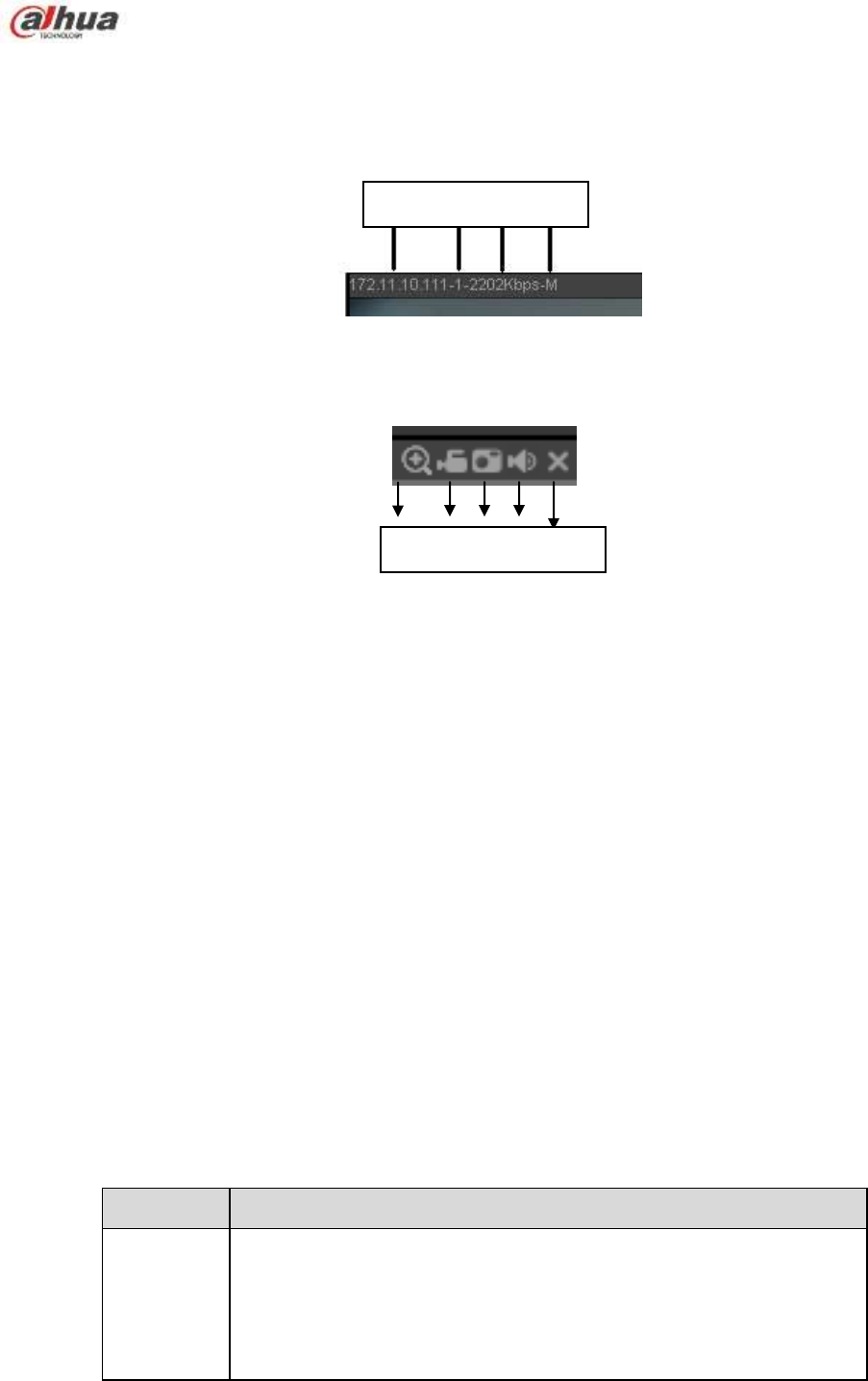
288
In section 2, left click the channel name you want to view, you can see the corresponding video in current
window.
On the top left corner, you can view device IP(172.11.10.11), channel number(1), network monitor bit
stream(2202Kbps) and stream type(M=main stream, S=sub stream). See Figure 5-10.
Figure 5-10
On the top right corner, there are six unction buttons. See Figure 5-11.
Figure 5-11
1: Digital zoom: Click this button and then left drag the mouse in the zone to zoom in. right click
mouse system restores original status.
2: Local record. When you click local record button, the system begins recording and this button
becomes highlighted. You can go to system folder RecordDownload to view the recorded file.
3: Snapshot picture. You can snapshot important video. All images are memorized in system client
folder PictureDownload (default).
4: Audio :Turn on or off audio.(It has no relationship with system audio setup )
5: Close video.
5.4 PTZ
Before PTZ operation, please make sure you have properly set PTZ protocol. (Please refer to chapter
5.8.5.10).
There are eight direction keys. In the middle of the eight direction keys, there is a 3D intelligent
positioning key.
Click 3D intelligent positioning key, system goes back to the single screen mode. Drag the mouse in the
screen to adjust section size. It can realize PTZ automatically.
Please refer to the following sheet for PTZ setup information.
Parameter
Function
Scan
Select Scan from the dropdown list.
Click Set button, you can set scan left and right limit.
Use direction buttons to move the camera to you desired location
and then click left limit button. Then move the camera again and
then click right limit button to set a right limit.
1 2 3 4 5
1 2 3 4
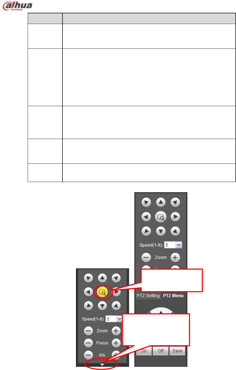
289
Parameter
Function
Preset
Select Preset from the dropdown list.
Turn the camera to the corresponding position and Input the
preset value. Click Add button to add a preset.
Tour
Select Tour from the dropdown list.
Input preset value in the column. Click Add preset button, you
have added one preset in the tour.
Repeat the above procedures you can add more presets in one
tour.
Or you can click delete preset button to remove one preset from
the tour.
Pattern
Select Pattern from the dropdown list.
You can input pattern value and then click Start button to begin
PTZ movement such as zoom, focus, iris, direction and etc. Then
you can click Add button to set one pattern.
Aux
Please input the corresponding aux value here.
You can select one option and then click AUX on or AUX off
button.
Light and
wiper
You can turn on or turn off the light/wiper.
Figure 5-12
You can click this icon to
display or hide the PTZ
control platform.
3D Intelligent Positioning
Key
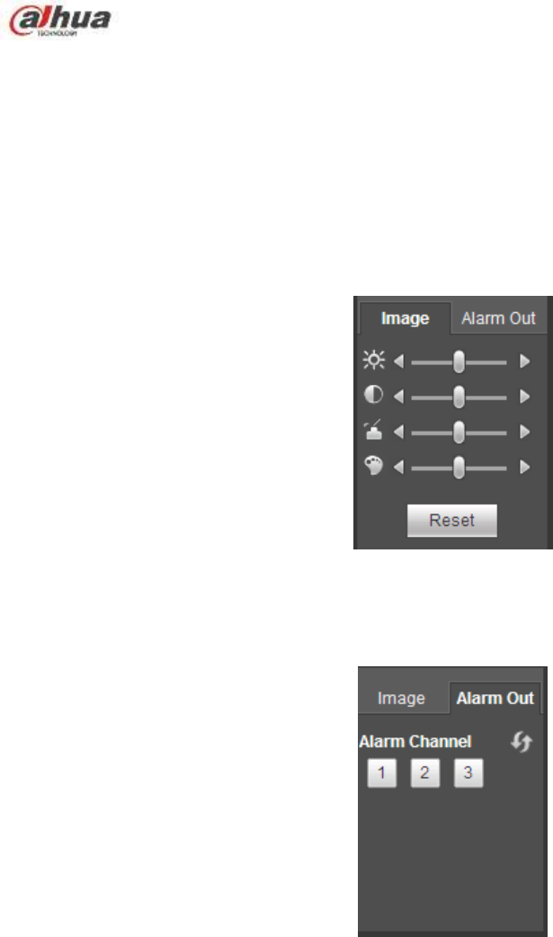
290
5.5 Image/Alarm-out
Select one monitor channel video and then click Image button in section 9, the interface is shown as
Figure 5-13.
5.5.1 Image
Here you can adjust its brightness, contrast, hue and saturation. (Current channel border becomes
green).
Or you can click Reset button to restore system default setup.
Figure 5-13
5.5.2 Alarm output
Here you can enable or disable the alarm signal of the corresponding port. See Figure 5-14.
Figure 5-14
5.6 Zero-channel Encode
Select a window and then click zero-channel encode button, the interface is shown as below. See Figure
5-15.
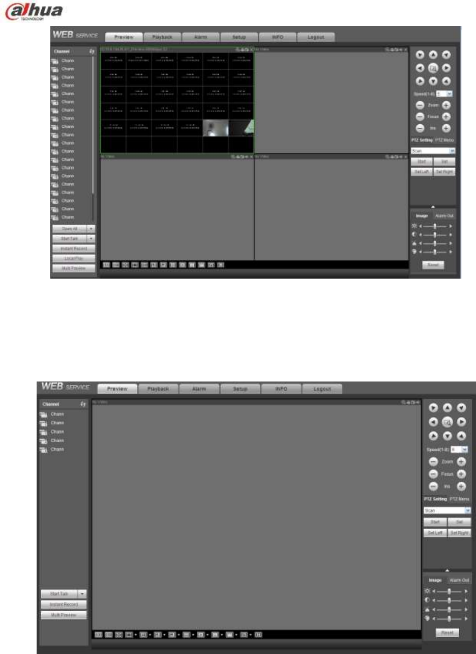
291
Figure 5-15
5.7 WAN Login
In WAN mode, after you logged in, the interface is shown as below. See Figure 5-16.
Figure 5-16
Please refer to the following contents for LAN and WAN login difference.
1) In the WAN mode, system opens the main stream of the first channel to monitor by default. The
open/close button on the left pane is null.
2) You can select different channels and different monitor modes at the bottom of the interface. See
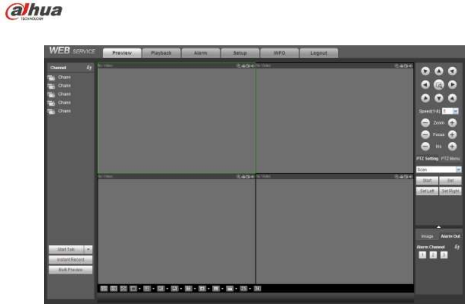
292
Figure 5-17.
Figure 5-17
Important
The window display mode and the channel number are by default. For example, for the 16-channel,
the max window split mode is 16.
3) Multiple-channel monitor, system adopts extra stream to monitor by default. Double click one channel,
system switches to single channel and system uses main stream to monitor. You can view there are two
icons at the left top corner of the channel number for you reference. M stands for main stream. S stands
for sub stream (extra stream).
4) If you login via the WAN mode, system does not support alarm activation to open the video function in
the Alarm setup interface.
Important
For multiple-channel monitor mode, system adopts extra stream to monitor by default. You can not
modify manually. All channels are trying to synchronize. Please note the synchronization effect still
depends on your network environments.
For bandwidth consideration, system can not support monitor and playback at the same time.
System auto closes monitor or playback interface when you are searching setup in the configuration
interface. It is to enhance search speed.
5.8 Setup
5.8.1 Camera
5.8.1.1 Registration
From Main menu->Setting->Camera->Registration, you can see the following interface. See Figure 5-18.
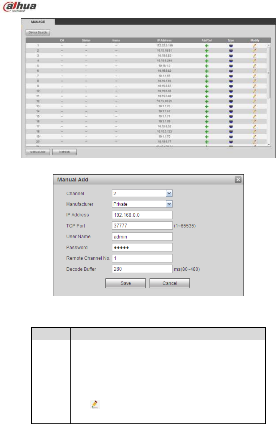
293
Figure 5-18
Figure 5-19
Please refer to the following sheet for parameter information.
Parameter
Function
Device
search
Click Device search button, you can view the searched device
information on the list. It includes device IP address, port, device
name, manufacturer and type.
Add
Select a device in the list and then click Add button, system can
connect the device automatically and add it to the Added device list.
Or you can double click one item in the list to add a device.
Modify
Click or any device in the Added device list, you can change the
corresponding channel setup.

294
Parameter
Function
Delete
Click , you can delete the remote connection of the corresponding
channel.
Type
There are two connection types. You can use the network to connect
to the camera or use the WIFI. The means current network
camera connection mode is general; the means current
network camera mode is hotspot.
Delete
Select a device in the Added device list and then click Delete button,
system can disconnect the device and remove it from the Added
device list.
Manual
Add
Click it, the interface is shown as in Figure 5-19. Here you can add
network camera manually.
You can select a channel from the dropdown list (Here only shows
disconnection channel.)
Note:
System supports manufactures such as Panasonic, Sony,
Dynacolor, Samsung, AXIS, Arecont, Dahua and Onvif standard
protocol.
If you do not input IP address here. System uses default IP
192.168.0.0 and system does not connect to this IP.
Can not add two devices at the same time. Click OK button here,
system only connect to the corresponding device of current
channel.
5.8.1.2 Image
Note
Slight difference may be found since the connected network camera may not be same model.
Here you can view device property information. The setups become valid immediately after you set. See
Figure 5-20.

295
Figure 5-20
Please refer to the following sheet for detailed information.
Parameter
Function
Channel
Please select a channel from the dropdown list.
Period
It divides one day (24 hours) to two periods. You can set
different hue, brightness, and contrast for different periods.
Hue
It is to adjust monitor video brightness and darkness level. The
default value is 50.
The bigger the value is, the large the contrast between the bright
and dark section is and vice versa.
Brightness
It is to adjust monitor window brightness. The default value is 50.
The larger the number is , the bright the video is. When you
input the value here, the bright section and the dark section of
the video will be adjusted accordingly. You can use this
function when the whole video is too dark or too bright. Please
note the video may become hazy if the value is too high. The
value ranges from 0 to 100.The recommended value ranges
from 40 to 60.
Contrast
It is to adjust monitor window contrast. The value ranges from 0
to 100. The default value is 50.
The larger the number is, the higher the contrast is. You can use
this function when the whole video bright is OK but the contrast
is not proper. Please note the video may become hazy if the
value is too low. If this value is too high, the dark section may
lack brightness while the bright section may over exposure .The
recommended value ranges from 40 to 60.
Saturation
It is to adjust monitor window saturation. The value ranges from
0 to 100. The default value is 50.
The larger the number is, the strong the color is. This value has
no effect on the general brightness of the whole video. The
video color may become too strong if the value is too high. For
the grey part of the video, the distortion may occur if the white
balance is not accurate. Please note the video may not be

296
attractive if the value is too low. The recommended value ranges
from 40 to 60.
Gain
The gain adjust is to set the gain value. The smaller the value is,
the low the noise is. But the brightness is also too low in the dark
environments. It can enhance the video brightness if the value is
high. But the video noise may become too clear.
White level
It is to enhance video effect.
Color mode
It includes several modes such as standard, color. You can
select corresponding color mode here, you can see hue,
brightness, and contrast and etc will adjust accordingly.
Auto Iris
It is to enable/disable auto iris function.
Flip
It is to switch video up and bottom limit.
This function is disabled by default.
Mirror
It is to switch video left and right limit.
This function is disabled by default.
BLC
Mode
BLC
The device auto exposures according to the environments
situation so that the darkest area of the video is cleared
WDR
For the WDR scene, this function can lower the high bright
section and enhance the brightness of the low bright section. So
that you can view these two sections clearly at the same time.
The value ranges from 1 to 100. When you switch the camera
from no-WDR mode to the WDR mode, system may lose several
seconds record video.
HLC
After you enabled HLC function, the device can lower the
brightness of the brightest section according to the HLC control
level. It can reduce the area of the halo and lower the brightness
of the whole video.
Off
It is to disable the BLC function. Please note this function is
disabled by default.
Profile
It is to set the white balance mode. It has effect on the general
hue of the video. This function is on by default.
You can select the different scene mode such as auto, sunny,
cloudy, home, office, night, disable and etc to adjust the video to
the best quality.
Auto: The auto white balance is on. System can auto
compensate the color temperature to make sure the vide
color is proper.
Sunny: The threshold of the white balance is in the sunny
mode.
Night: The threshold of the white balance is in the night
mode.
Customized: You can set the gain of the red/blue channel.
The value reneges from 0 to 100.
Day/Night
It is to set device color and the B/W mode switch. The default
setup is auto.
Color: Device outputs the color video.
Auto: Device auto select to output the color or the B/W
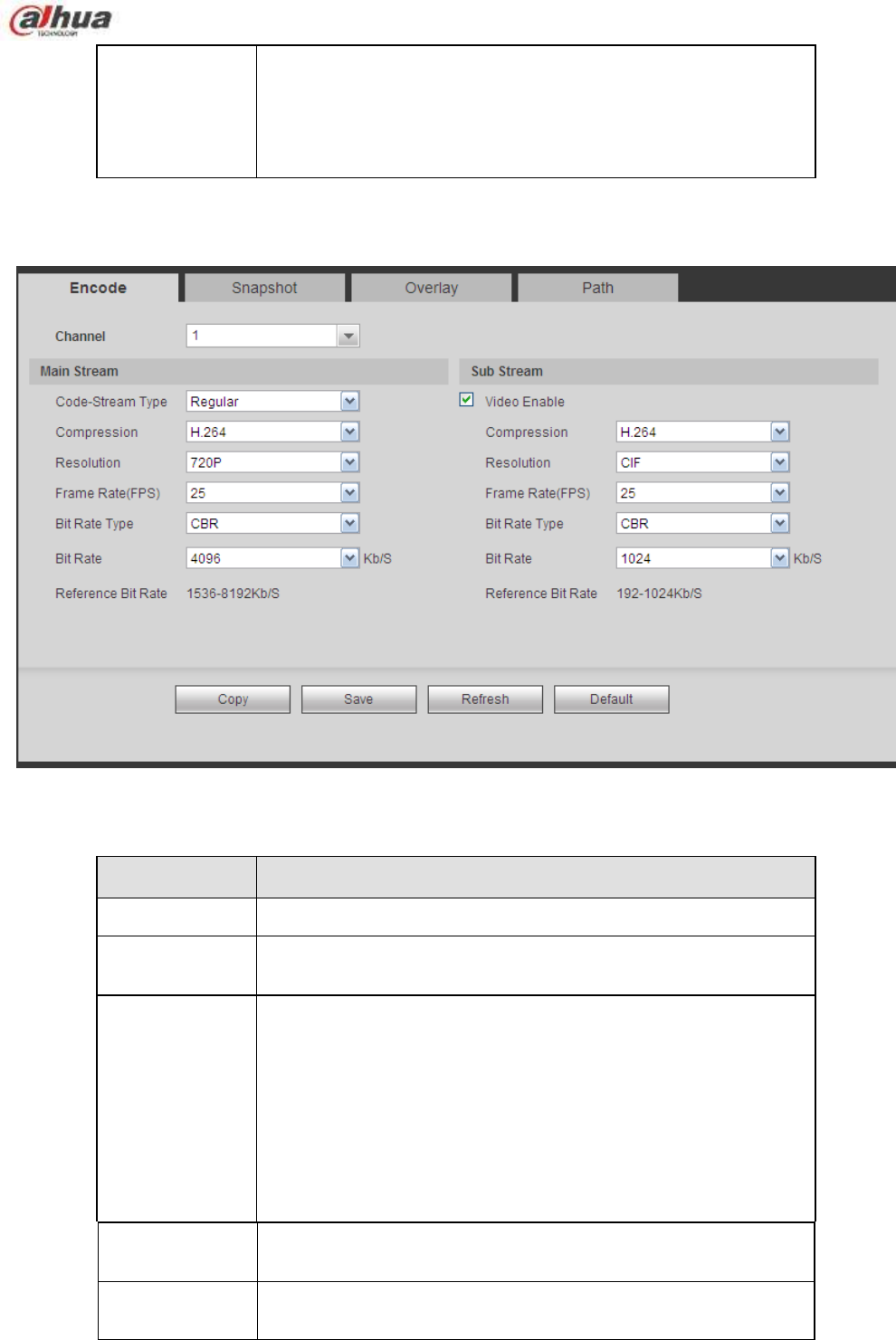
297
video according to the device feature (The general bright of
the video or there is IR light or not.)
B/W: The device outputs the black and white video.
Sensor: It is to set when there is peripheral connected IR
light.
5.8.1.3 Encode
5.8.1.3.1 Encode
The encode interface is shown as below. See Figure 5-21.
Figure 5-21
Please refer to the following sheet for detailed information.
Parameter
Function
Channel
Please select a channel from the dropdown list.
Video enable
Check the box here to enable extra stream video. This item is
enabled by default.
Code stream
type
It includes main stream, motion stream and alarm stream. You
can select different encode frame rates form different recorded
events.
System supports active control frame function (ACF). It allows
you to record in different frame rates.
For example, you can use high frame rate to record important
events, record scheduled event in lower frame rate and it allows
you to set different frame rates for motion detection record and
alarm record.
Compression
The main bit stream supports H.264. The extra stream supports
H.264, MJPG.
Resolution
The resolution here refers to the capability of the network
camera.
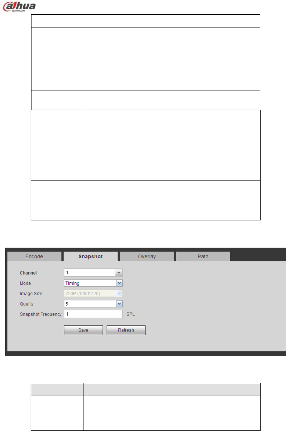
298
Frame Rate
PAL:1~25f/s;NTSC:1~30f/s.
Bit Rate
Main stream: You can set bit rate here to change video
quality. The large the bit rate is, the better the quality is.
Please refer to recommend bit rate for the detailed
information.
Extra stream: In CBR, the bit rate here is the max value.
In dynamic video, system needs to low frame rate or
video quality to guarantee the value. The value is null in
VBR mode.
Reference bit
rate
Recommended bit rate value according to the resolution and
frame rate you have set.
I Frame
Here you can set the P frame amount between two I frames. The
value ranges from 1 to 150. Default value is 50.
Recommended value is frame rate *2.
Enable audio
Check the box to enable audio function.
The audio of the main stream is enabled by default. When this
function is enabled, the record file has audio/video composite
stream. For the sub stream, please check the video first and
then enable audio.
Watermark
enable
This function allows you to verify the video is tampered or not.
Here you can select watermark bit stream, watermark mode and
watermark character. Default character is DigitalCCTV. The max
length is 85-digit. The character can only include number,
character and underline.
5.8.1.3.2 Snapshot
The snapshot interface is shown as in Figure 5-22.
Figure 5-22
Please refer to the following sheet for detailed information.
Parameter
Function
Snapshot type
There are two modes: Regular (schedule) and Trigger.
Regular snapshot is valid during the specified period you
set.
Trigger snapshot only is valid when motion detect alarm,
tampering alarm or local activation alarm occurs.
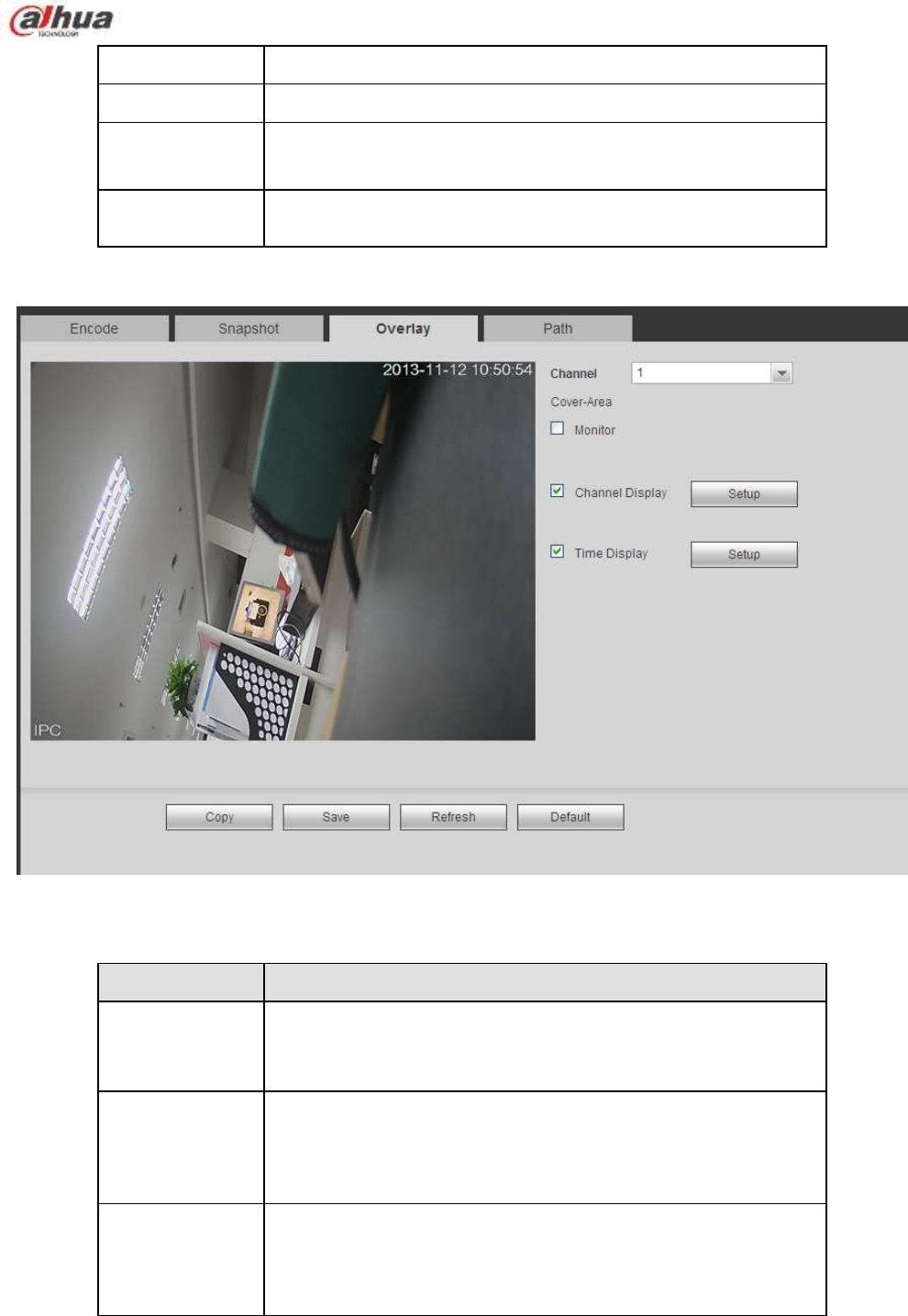
299
Image size
It is the same with the resolution of the main stream.
Quality
It is to set the image quality. There are six levels.
Interval
It is to set snapshot frequency. The value ranges from 1s to 7s.
Or you can set customized value. The max setup is
3600s/picture.
Copy
Click it; you can copy current channel setup to other channel(s).
5.8.1.3.3 Video Overlay
The video overlay interface is shown as in Figure 5-23.
Figure 5-23
Please refer to the following sheet for detailed information.
Parameter
Function
Cover-area
Check Preview or Monitor first.
Click Set button, you can privacy mask the specified video in the
preview or monitor video.
System max supports 4 privacy mask zones.
Time Title
You can enable this function so that system overlays time
information in video window.
You can use the mouse to drag the time title position.
You can view time title on the live video of the WEB or the
playback video.
Channel Title
You can enable this function so that system overlays channel
information in video window.
You can use the mouse to drag the channel title position.
You can view channel title on the live video of the WEB or the
playback video.
5.8.1.3.4 Path
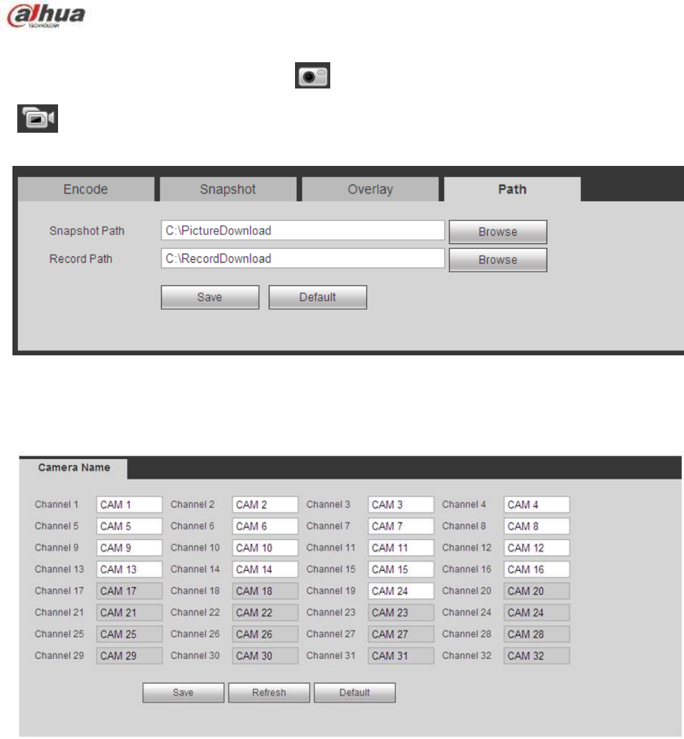
300
The storage path interface is shown as in Figure 5-24.
Here you can set snap image saved path ( in the preview interface) and the record storage path
( in the preview interface).The default setup is C:\PictureDownload and C:\RecordDownload.
Please click the Save button to save current setup.
Figure 5-24
5.8.1.4 Channel Name
Here you can set channel name. See Figure 5-25.
Figure 5-25
5.8.1.5 IPC Upgrade
This interface is to upgrade network camera. See Figure 5-26.
Click Browse button to select upgrade file. Or you can use filter to select several network cameras at the
same time.
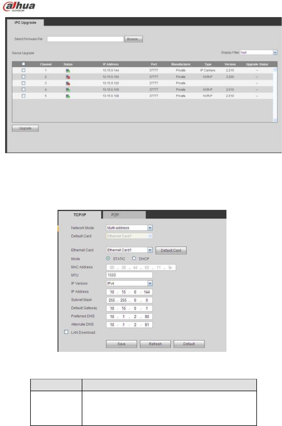
301
Figure 5-26
5.8.2 Network
5.8.2.1 TCP/IP
The TCP/IP interface is shown as in Figure 5-27.
Figure 5-27
Please refer to the following sheet for detailed information.
Parameter
Function
Mode
There are two modes: static mode and the DHCP mode.
The IP/submask/gateway are null when you select the
DHCP mode to auto search the IP.
If you select the static mode, you need to set the
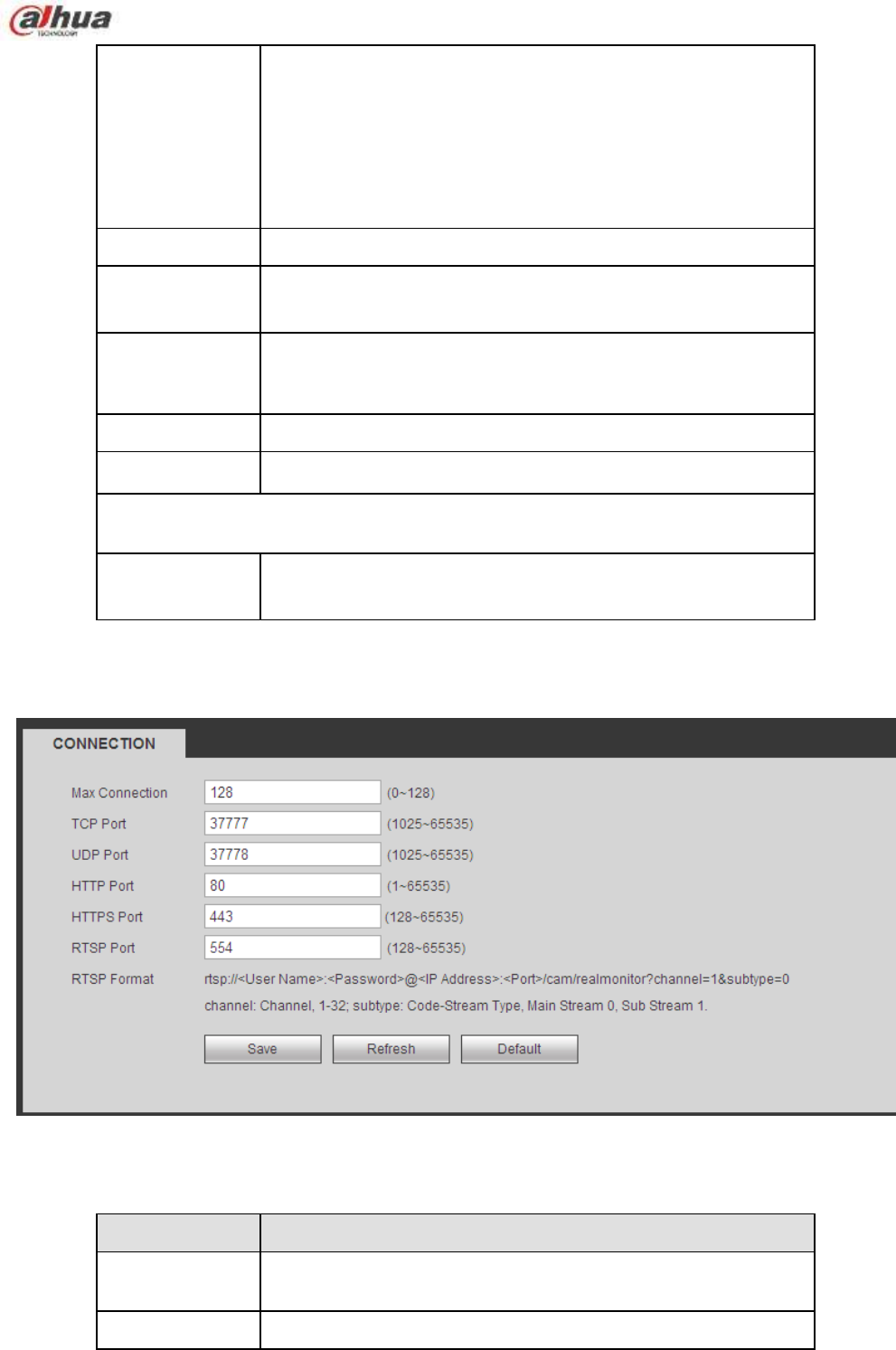
302
IP/submask/gateway manually.
If you select the DHCP mode, you can view the
IP/submask/gateway from the DHCP.
If you switch from the DHCP mode to the static mode, you
need to reset the IP parameters.
Besides, IP/submask/gateway and DHCP are read-only
when the PPPoE dial is OK.
Mac Address
It is to display host Mac address.
IP Version
It is to select IP version. IPV4 or IPV6.
You can access the IP address of these two versions.
IP Address
Please use the keyboard to input the corresponding number to
modify the IP address and then set the corresponding subnet
mask and the default gateway.
Preferred DNS
DNS IP address.
Alternate DNS
Alternate DNS IP address.
For the IP address of IPv6 version, default gateway, preferred DNS and
alternate DNS, the input value shall be 128-digit. It shall not be left in blank.
LAN load
System can process the downloaded data first if you enable this
function. The download speed is 1.5X or 2.0X of the normal
speed.
5.8.2.2 Connection
The connection interface is shown as in Figure 5-28.
Figure 5-28
Please refer to the following sheet for detailed information.
Parameter
Function
Max connection
It is the max Web connection for the same device. The value
ranges from 1 to 120. The default setup is 120.
TCP port
The default value is 37777. You can input the actual port
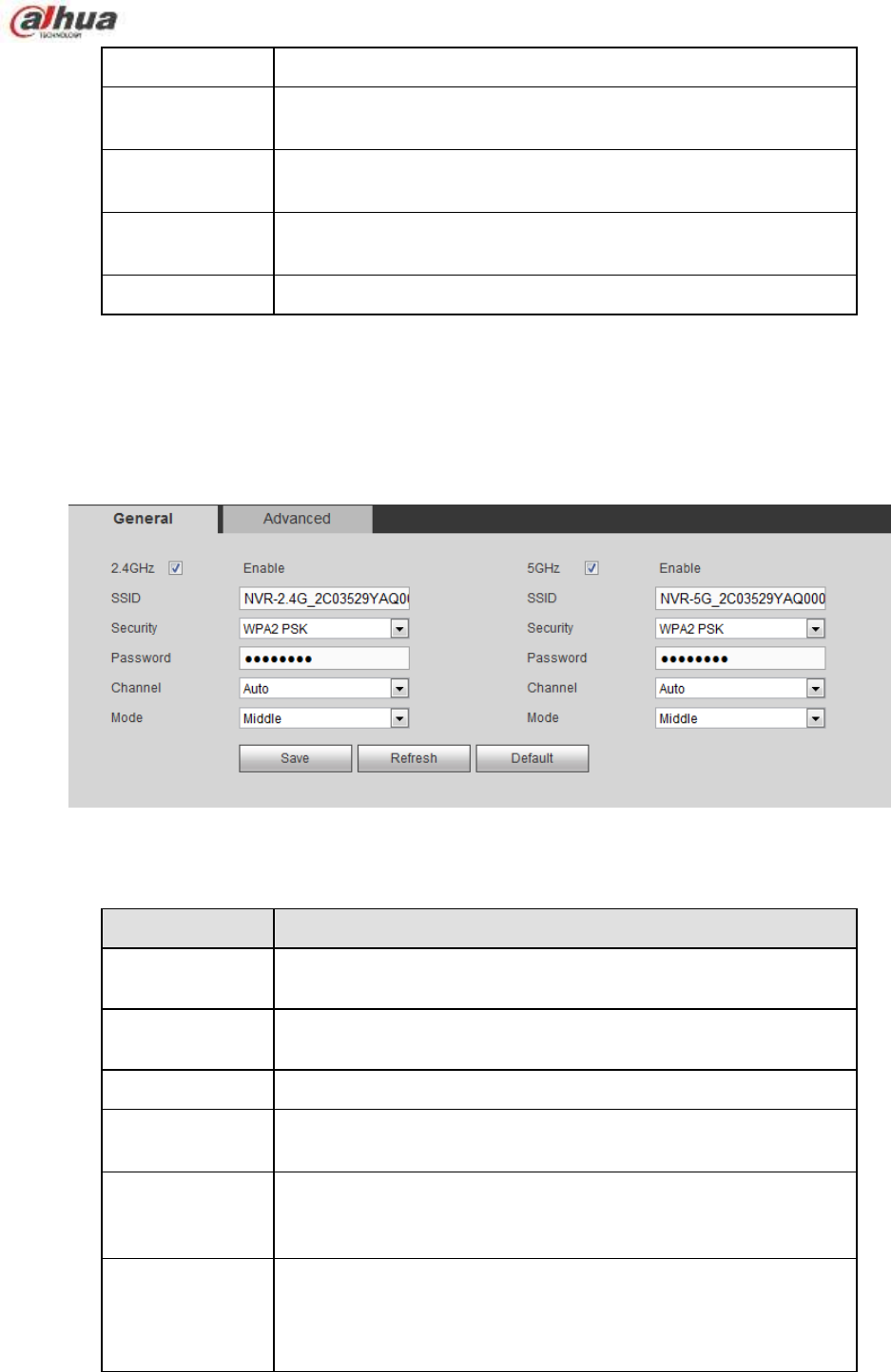
303
number if necessary.
UDP port
The default value is 37778. You can input the actual port
number if necessary.
HTTP port
The default value is 80. You can input the actual port number if
necessary.
HTTPS
The default value is 443. You can input the actual port number if
necessary.
RTSP port
The default value is 554.
5.8.2.3 WIFI AP
Please note this function is for some series only.
5.8.2.3.1 General Setup
The WIFI AP interface is shown as in Figure 5-29. Here you can set WIFI hotspot, so that the network
camera can use the hotspot to connect to the network.
Figure 5-29
Please refer to the following sheet for detailed information.
Parameter
Function
SSID
It is to set SSID name. You can use this name to search the
device.
Password
It is to set SSID password. You can use this password to
connect to the network.
Seucurity
Select authentication from the dropdown list.
Start IP/End IP
Input start IP and end IP. The NVR can allocate the IP address
in the range you specified here.
WPS
Click WPS button to enable WPS function. After the network
camera enabled this function, it can automatically connect to the
network.
Remote device
In the list, you can view the network camera(s) that connected
to the NVR. It includes signal intensity, IP, MAC address, bit
rate, channel number, type, status and etc.
5.8.2.3.2 Advanced
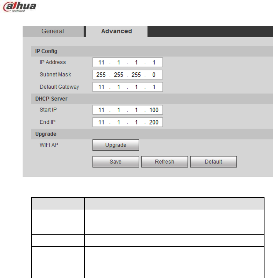
304
Click Advanced butto, the interface is shown as below. See Figure 5-30.
Figure 5-30
Please refer to the following sheet for detailed information.
Parameter
Function
IPv4 address
Input WIFI AP IP address.
IPv4 netmask
Input WIFI AP network mask.
IPv4 gateway
Input WIFI AP gateway.
Start IP/End IP
Input start IP and end IP. The NVR can allocate the IP address
in the range you specified here.
Upgrade
Click it to upgrade WIFI AP module.
5.8.2.4 WIFI
Please note this function is for the device of WIFI module.
The WIFI interface is shown as in Figure 5-31.
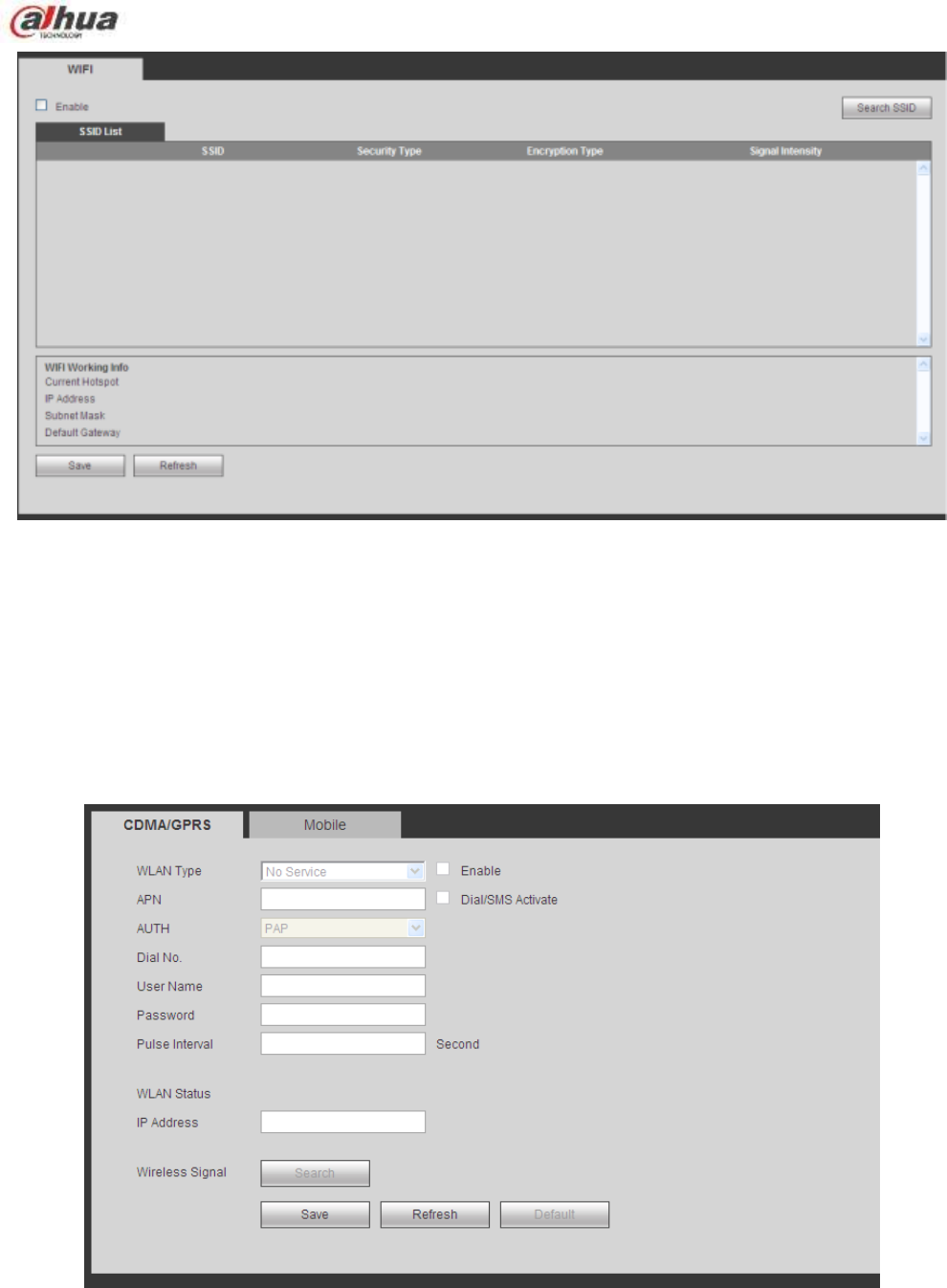
305
Figure 5-31
Please check the box to enable WIFI function and then click the Search SSID button. Now you can view
all the wireless network information in the following list. Double click a name to connect to it. Click
Refresh button, you can view latest connection status.
5.8.2.5 3G
5.8.2.5.1 CDMA/GPRS
The CDMA/GPRS interface is shown as in Figure 5-32.
Figure 5-32
Please refer to the following sheet for detailed information.
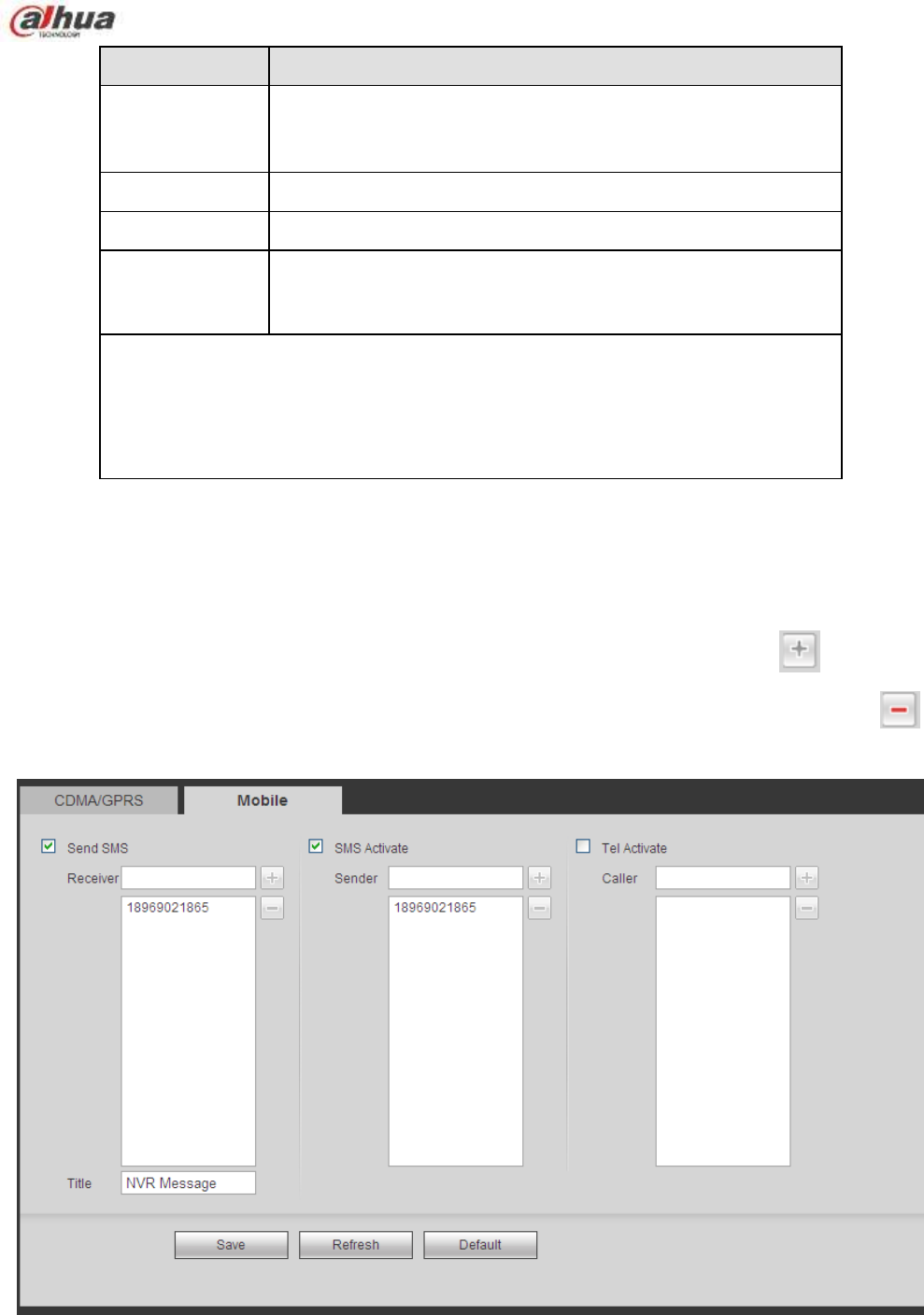
306
Parameter
Function
WLAN type
Here you can select 3G network type to distinguish the 3G
module from different ISP. The types include WCDMA,
CDMA1x and etc.
APN/Dial No.
Here is the important parameter of PPP.
Authorization
It includes PAP,CHAP,NO_AUTH.
Pulse interval
It is to set time to end 3G connection after you close extra
stream monitor. For example, if you input 60 here, system ends
3G connection after you close extra stream monitor 60 seconds.
Important
If the pulse interval is 0, then system does not end 3G connection after
you close the extra stream monitor.
Pulse interval here is for extra stream only. This item is null if you are
using main stream to monitor.
5.8.2.5.2 Mobile
The mobile setup interface is shown as in Figure 5-33.
Here you can activate (send out ―on‖) or turn off (Send out ―off‖) the 3G connected phone or mobile phone,
or the phone you set to get alarm message.
Check send SMS box and then input the phone number in the receiver column. Click to add one
receiver. Repeat the above steps you can add more phones. Select a phone number and then click ,
you can delete it. Click OK button to complete the setup.
Figure 5-33
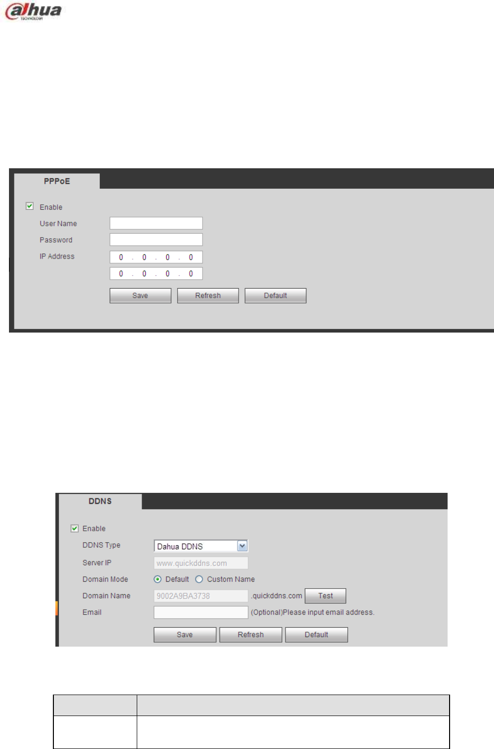
307
5.8.2.6 PPPoE
The PPPoE interface is shown as in Figure 5-34.
Input the PPPoE user name and password you get from the IPS (internet service provider) and enable
PPPoE function. Please save current setup and then reboot the device to get the setup activated.
Device connects to the internet via PPPoE after reboot. You can get the IP address in the WAN from the
IP address column.
Please note, you need to use previous IP address in the LAN to login the device. Please go to the
IP address item to via the device current device information. You can access the client-end via
this new address.
Figure 5-34
5.8.2.7 DDNS
The DDNS interface is shown as in Figure 5-35.
The DDNS is to set to connect the various servers so that you can access the system via the server.
Please go to the corresponding service website to apply a domain name and then access the system via
the domain. It works even your IP address has changed.
Please select DDNS from the dropdown list (Multiple choices). Before you use this function, please make
sure your purchased device support current function.
Figure 5-35
Please refer to the following sheet for detailed information.
Parameter
Function
Server Type
You can select DDNS protocol from the dropdown list and then
enable DDNS function.

308
Parameter
Function
Server IP
DDNS server IP address
Server Port
DDNS server port.
Domain Name
Your self-defined domain name.
User
The user name you input to log in the server.
Password
The password you input to log in the server.
Update period
Device sends out alive signal to the server regularly.
You can set interval value between the device and DDNS server
here.
Dahua DDNS and Client-end Introduction
1) Background Introduction
Device IP is not fixed if you use ADSL to login the network. The DDNS function allows you to access the
NVR via the registered domain name. Besides the general DDNS, the Dahua DDNS works with the
device from the manufacturer so that it can add the extension function.
2) Function Introduction
The Dahua DDNS client has the same function as other DDNS client end. It realizes the bonding of the
domain name and the IP address. Right now, current DDNS server is for our own devices only. You need
to refresh the bonding relationship of the domain and the IP regularly. There is no user name, password
or the ID registration on the server. At the same time, each device has a default domain name (Generated
by MAC address) for your option. You can also use customized valid domain name (has not registered.).
3) Operation
Before you use Dahua DDNS, you need to enable this service and set proper server address, port value
and domain name.
Server address:www.dahuaddns.com
Port number:80
Domain name:There are two modes: Default domain name and customized domain name.
Except default domain name registration, you can also use customized domain name (You can input your
self-defined domain name.) After successful registration, you can use domain name to login installed of
the device IP.
User name: It is optional. You can input your commonly used email address.
Important
Do not register frequently. The interval between two registrations shall be more than 60 seconds. Too
many registration requests may result in server attack.
System may take back the domain name that is idle for one year. You can get a notification email
before the cancel operation if your email address setup is OK.
5.8.2.8 IP filter
The IP filter interface is shown as in Figure 5-36.
After you enabled trusted sites function, only the IP listed below can access current NVR.
If you enable blocked sites function, the following listed IP addresses can not access current NVR.
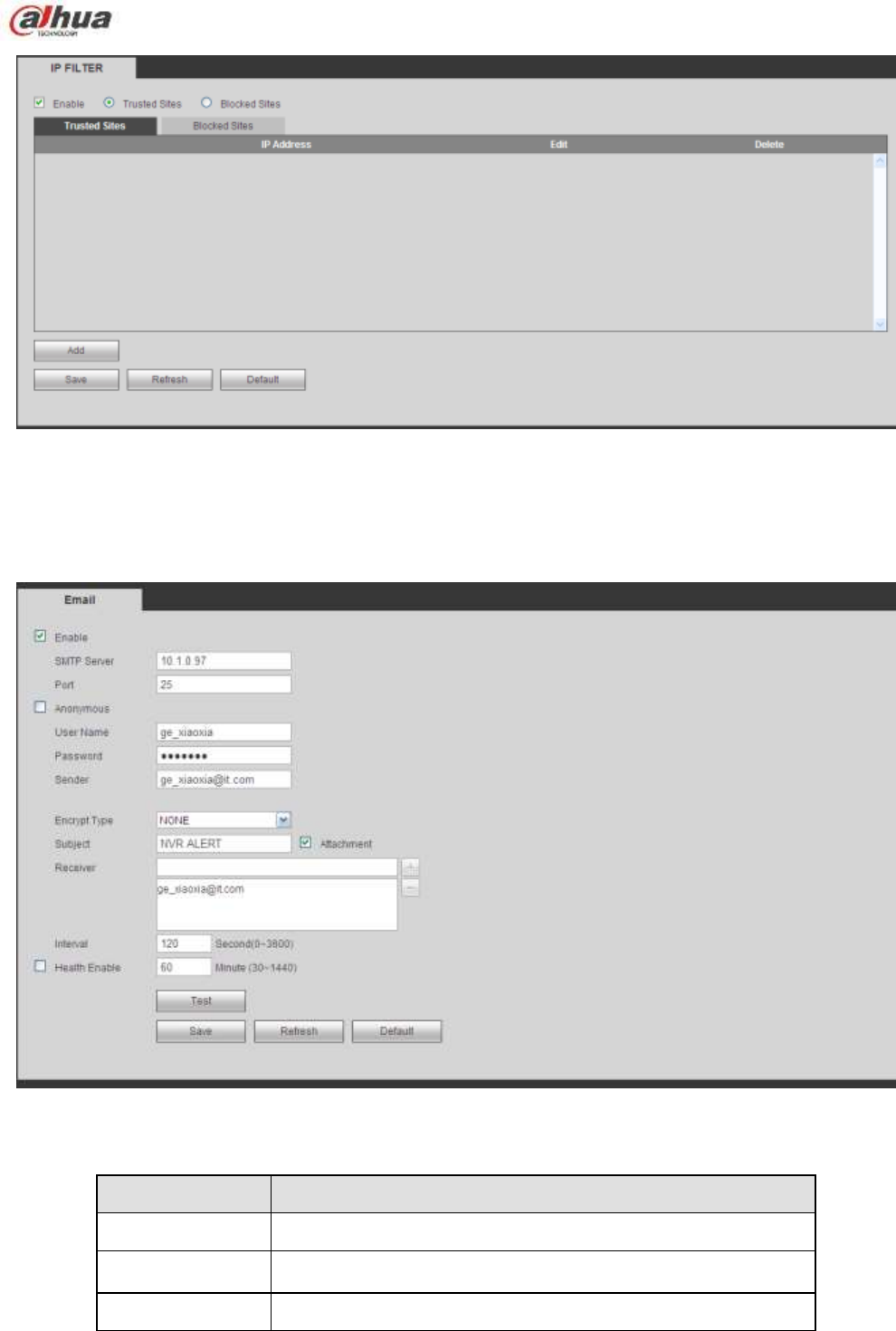
309
Figure 5-36
5.8.2.9 Email
The email interface is shown as in Figure 5-37.
Figure 5-37
Please refer to the following sheet for detailed information.
Parameter
Function
Enable
Please check the box here to enable email function.
SMTP Server
Input server address and then enable this function.
Port
Default value is 25. You can modify it if necessary.

310
Parameter
Function
Anonymity
For the server supports the anonymity function. You can auto
login anonymously. You do not need to input the user name.
password and the sender information.
User Name
The user name of the sender email account.
Password
The password of sender email account.
Sender
Sender email address.
Authentication
(Encryption
mode)
You can select SSL or none.
Subject
Input email subject here.
Attachment
System can send out the email of the snapshot picture once
you check the box here.
Receiver
Input receiver email address here. Max three addresses.
It supports SSL, TLS email box.
Interval
The send interval ranges from 0 to 3600 seconds. 0 means
there is no interval.
Please note system will not send out the email immediately
when the alarm occurs. When the alarm, motion detection or
the abnormity event activates the email, system sends out the
email according to the interval you specified here. This
function is very useful when there are too many emails
activated by the abnormity events, which may result in heavy
load for the email server.
Health mail
enable
Please check the box here to enable this function.
Update period
(interval)
This function allows the system to send out the test email to
check the connection is OK or not.
Please check the box to enable this function and then set the
corresponding interval. The value ranges from 30 minutes to
1440 minutes.
System can send out the email regularly as you set here.
Email test
The system will automatically sent out a email once to test the
connection is OK or not .Before the email test, please save the
email setup information.
5.8.2.10 UPnP
It allows you to establish the mapping relationship between the LAN and the public network.
Here you can also add, modify or remove UPnP item. See Figure 5-38.
In the Windows OS, From Start->Control Panel->Add or remove programs. Click the ―Add/Remove
Windows Components‖ and then select the ―Network Services‖ from the Windows Components
Wizard.
Click the Details button and then check the ―Internet Gateway Device Discovery and Control client‖
and ―UPnP User Interface‖. Please click OK to begin installation.
Enable UPnP from the Web. If your UPnP is enabled in the Windows OS, the NVR can auto detect it
via the ―My Network Places‖
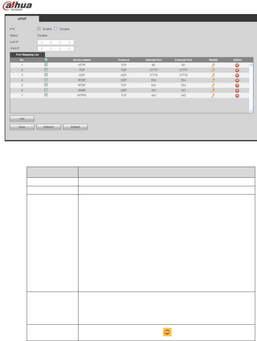
311
Figure 5-38
Please refer to the following sheet for detailed information.
Parameter
Function
PAT
Check the corresponding box to enable PAT function.
Status
Display UPnP function status.
Port mapping list
It is corresponding to the UPnP mapping information on the router.
Check the box before the service name to enable current PAT service.
Otherwise, the service is null.
Service name:Customized name.
Protocol:Protocol type.
Internal port:The port mapped to the port.
External port:The port current device needs to map.
Device has three mapping items: HTTP/TCP/UDP.
Note
When you set the external port (outport) of the router, the value ranges
from 1024 to 5000. Do not use port 1~255 or system port 256~1023,
in case there is conflict.
Add
Click Add button to add map relationship.
Note
For the data transmission protocol TCP/UDP, the external port and the
internal port shall be the same to guarantee proper data transmission.
Delete
Select one service and then click to delete map relationship.
5.8.2.11 SNMP
The SNMP interface is shown as in Figure 5-39.
The SNMP allows the communication between the network management work station software and the
proxy of the managed device. It is reserved for the 3rd party to develop.
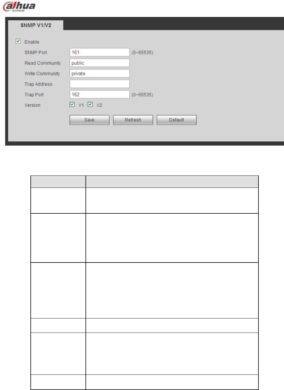
312
Figure 5-39
Please refer to the following sheet for detailed information.
Parameter
Function
SNMP Port
The listening port of the proxy program of the device. It is a
UDP port not a TCP port. The value ranges from 1 to 65535.
The default value is 161
Read Community
It is a string. It is a command between the manage process
and the proxy process. It defined the authentication, access
control and the management relationship between one proxy
and one group of the managers. Please make sure the device
and the proxy are the same.
The read community will read all the objects the SNMP
supported in the specified name. The default setup is public.
Write Community
It is a string. It is a command between the manage process
and the proxy process. It defined the authentication, access
control and the management relationship between one proxy
and one group of the managers. Please make sure the device
and the proxy are the same.
The read community will read/write/access all the objects the
SNMP supported in the specified name. The default setup is
write.
Trap address
The destination address of the Trap information from the proxy
program of the device.
Trap port
The destination port of the Trap information from the proxy
program of the device. It is for the gateway device and the
client-end PC in the LAN to exchange the information. It is a
non-protocol connection port. It has no effect on the network
applications. It is a UDP port not TCP port. The value ranges
from 1 to 165535. The default value is 162.
SNMP version
Check V1, system only processes the information of V1.
Check V2, system only processes the information of V2.
5.8.2.12 Multicast
The multicast interface is shown as in Figure 5-40.
Multicast is a transmission mode of data packet. When there is multiple-host to receive the same data
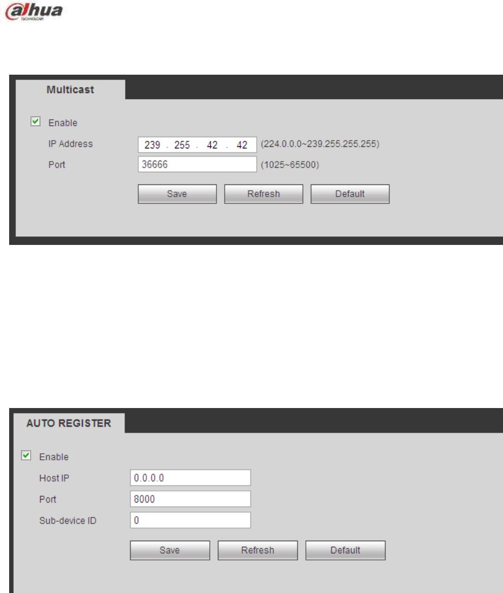
313
packet, multiple-cast is the best option to reduce the broad width and the CPU load. The source host
can just send out one data to transit. This function also depends on the relationship of the group member
and group of the outer.
Figure 5-40
5.8.2.13 Auto Register
The auto register interface is shown as below. See Figure 5-41.
This function allows the device to auto register to the proxy you specified. In this way, you can use the
client-end to access the NVR and etc via the proxy. Here the proxy has a switch function. In the network
service, device supports the server address of IPv4 or domain.
Please follow the steps listed below to use this function.
Please set proxy server address, port, and sub-device name at the device-end. Please enable the auto
register function, the device can auto register to the proxy server.
Figure 5-41
5.8.2.14 Alarm Centre
The alarm center interface is shown as below. See Figure 5-42.
This interface is reserved for you to develop. System can upload alarm signal to the alarm center when
local alarm occurs.
Before you use alarm center, please set server IP, port and etc. When an alarm occurs, system can send
out data as the protocol defined, so the client-end can get the data.

314
Figure 5-42
5.8.2.15 HTTPS
In this interface, you can set to make sure the PC can successfully login via the HTTPS. It is to guarantee
communication data security. The reliable and stable technology can secure the user information security
and device safety. See Figure 5-43.
Note
You need to implement server certificate again if you have changed device IP.
You need to download root certificate if it is your first time to use HTTPS on current PC.
Figure 5-43
5.8.2.15.1 Create Server Certificate
If it is your first time to use this function, please follow the steps listed below.
In Figure 5-43, click button, input country name, state name and etc. Click
Create button. See Figure 5-44.
Note
Please make sure the IP or domain information is the same as your device IP or domain name.
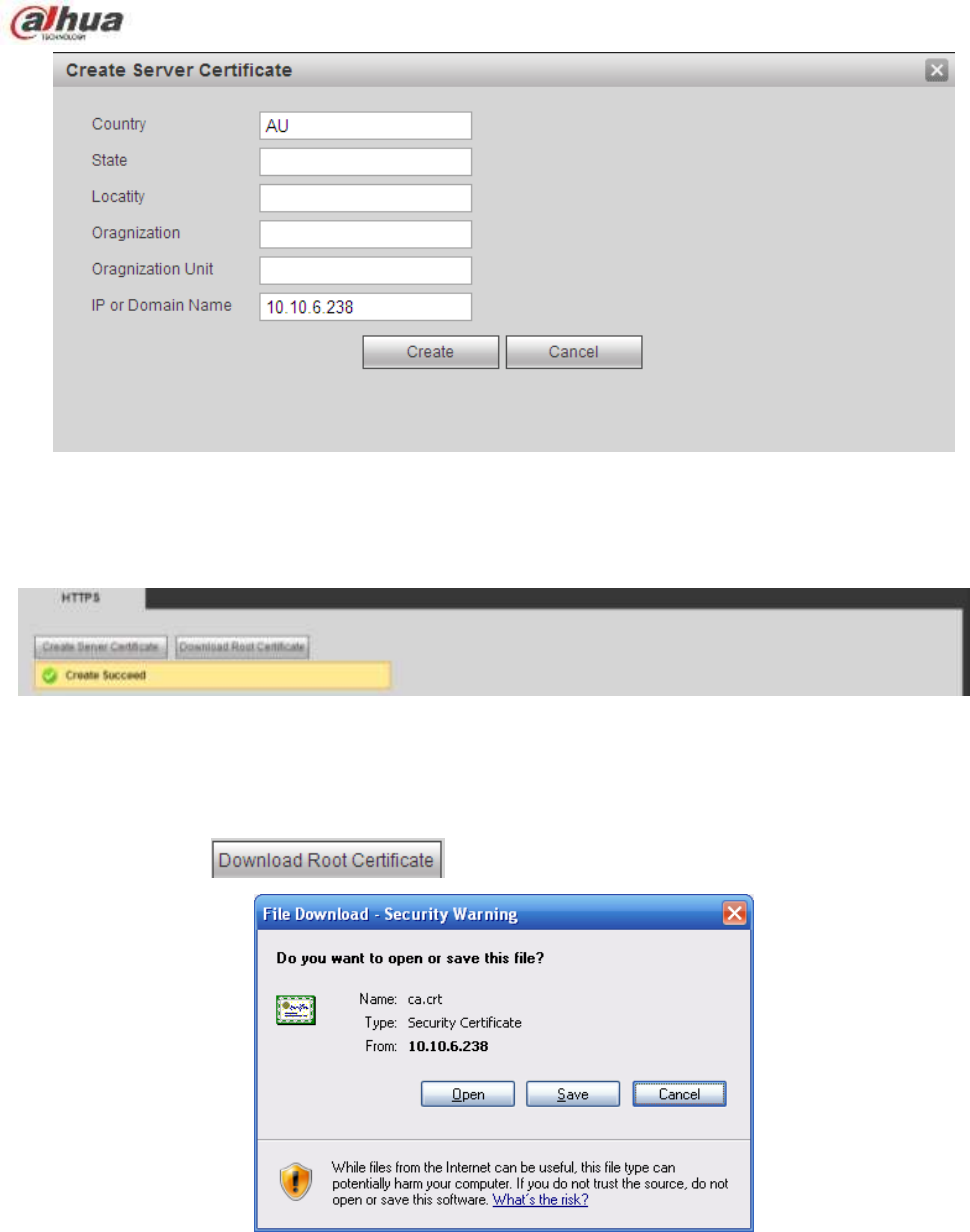
315
Figure 5-44
You can see the corresponding prompt. See Figure 5-45. Now the server certificate is successfully
created.
Figure 5-45
5.8.2.15.2 Download root certificate
In Figure 5-43, click button, system pops up a dialogue box. See Figure 5-46.
Figure 5-46
Click Open button, you can go to the following interface. See Figure 5-47.
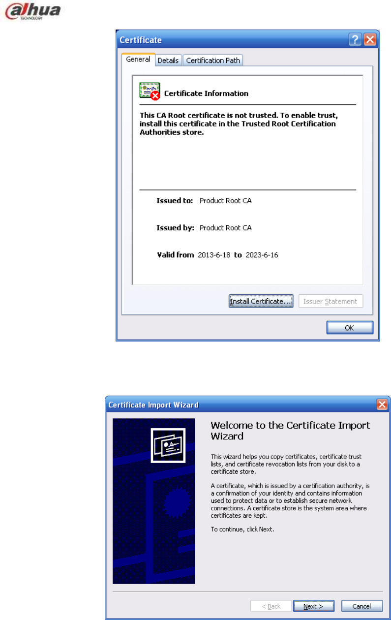
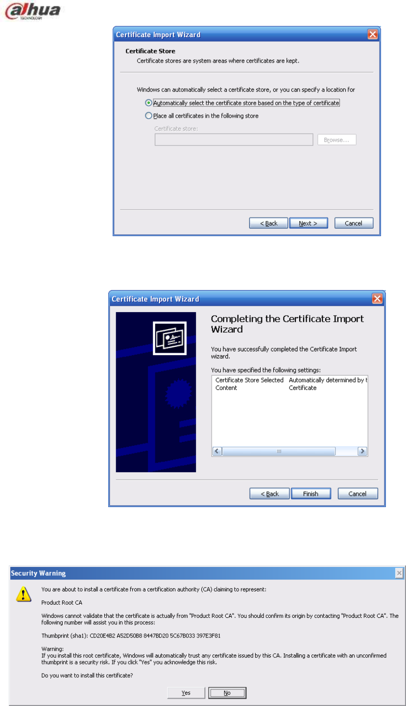
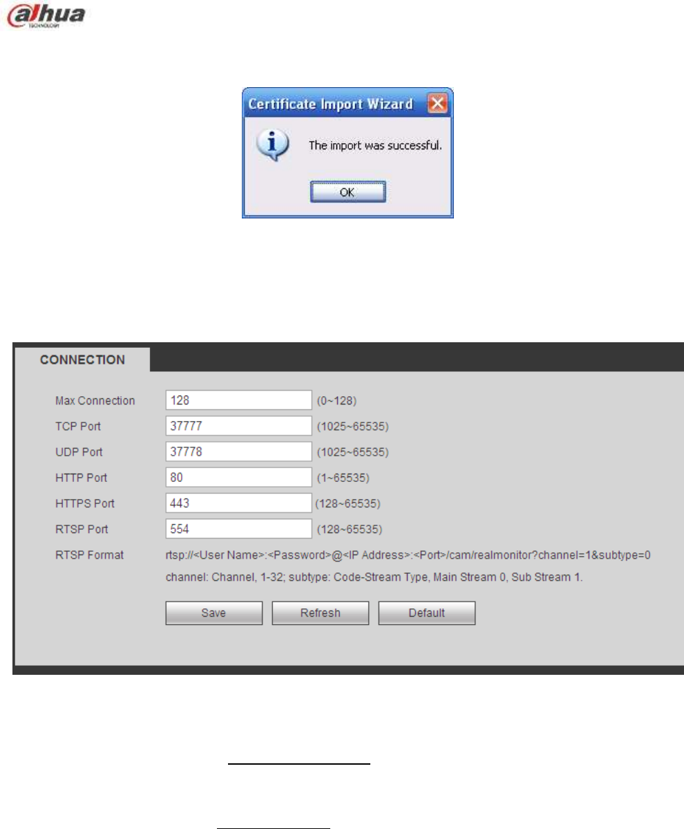
318
Click Yes button, system pops up the following dialogue box, you can see the certificate download is
complete. See Figure 5-52.
Figure 5-52
5.8.2.15.3 View and set HTTPS port
From Setup->Network->Connection, you can see the following interface. See Figure 5-53.
You can see HTTPS default value is 443.
Figure 5-53
5.8.2.15.4 Login
Open the browser and then input https://xx.xx.xx.xx:port.
xx.xx.xx.xx: is your device IP or domain mane.
Port is your HTTPS port. If you are using default HTTPS value 443, you do not need to add port
information here. You can input https://xx.xx.xx.xx to access.
Now you can see the login interface if your setup is right.
5.8.2.16 P2P
You can use your cell phone to scan the QR code and add it to the cell phone client.
Via the SN from scanning the QR code, you can access the device in the WAN. Please refer to the P2P
operation manual included in the resources CD.
The P2P interface is shown as in Figure 5-54.
Check the Enable box to enable P2P function and then click the Save button. Now you can view the
device status and SN.
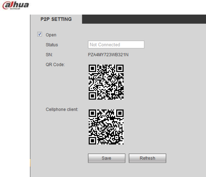
319
Figure 5-54
5.8.3 Event
5.8.3.1 Video detect
5.8.3.1.1 Motion Detect
After analysis video, system can generate a video loss alarm when the detected moving signal reached
the sensitivity you set here.
The motion detect interface is shown as in Figure 5-55.
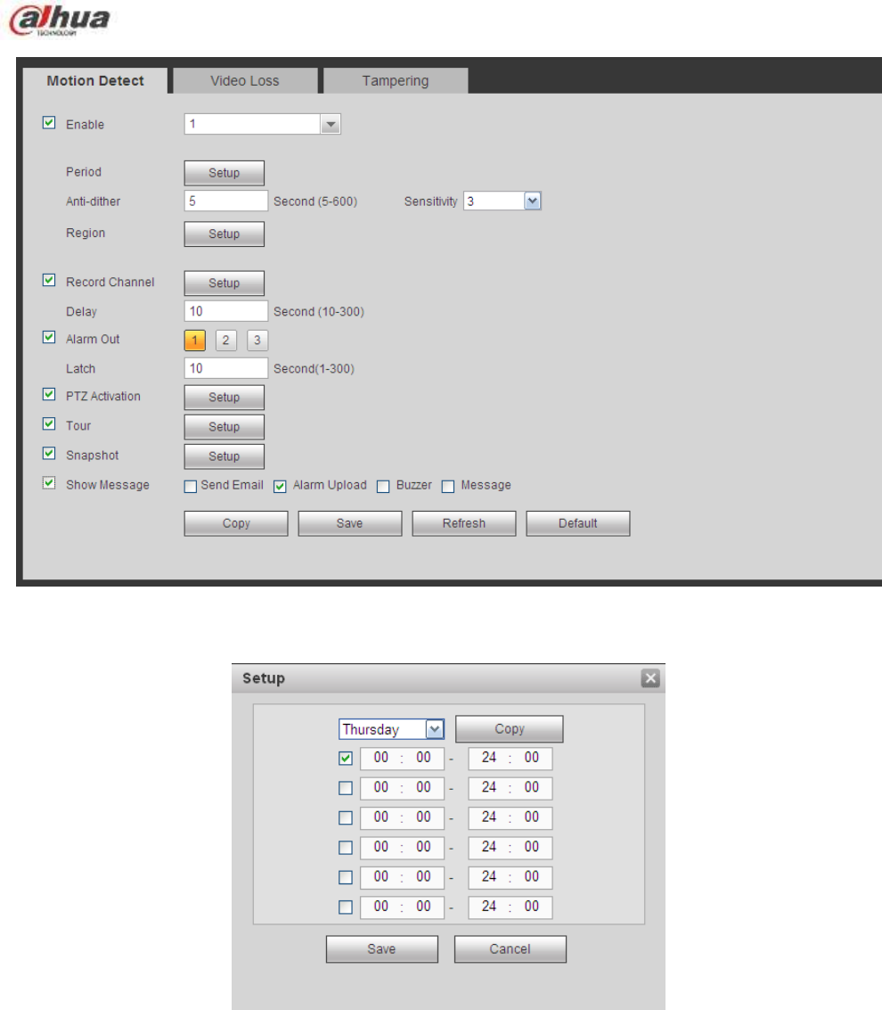
320
Figure 5-55
Figure 5-56
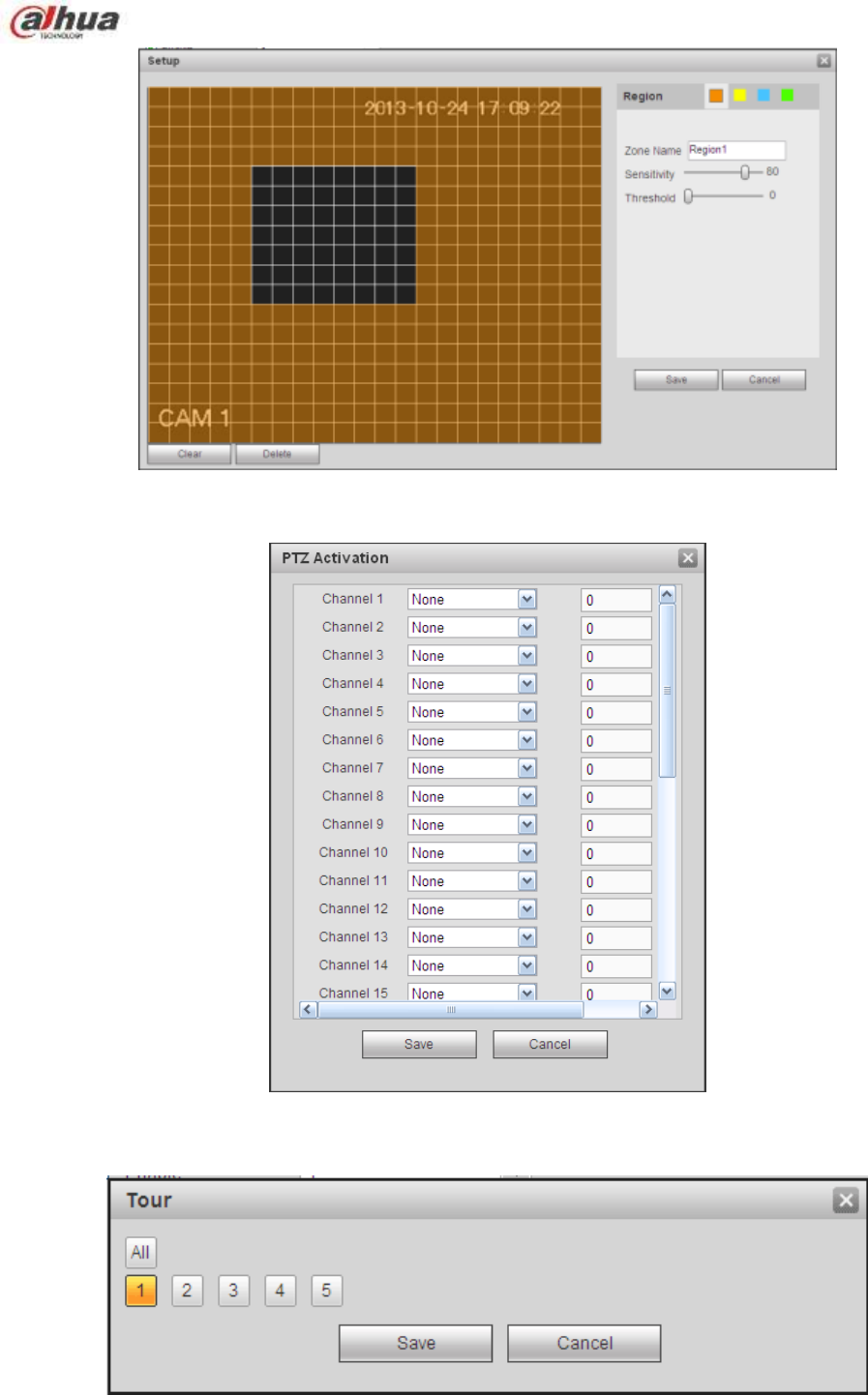
321
Figure 5-57
Figure 5-58
Figure 5-59

322
Figure 5-60
Please refer to the following sheet for detailed information.
Parameter
Function
Enable
You need to check the box to enable motion detection function.
Please select a channel from the dropdown list.
Period
Motion detection function becomes activated in the specified
periods. See Figure 5-56.
There are six periods in one day. Please draw a circle to enable
corresponding period.
Click OK button, system goes back to motion detection interface,
please click save button to exit.
Anti-dither
System only memorizes one event during the anti-dither period.
The value ranges from 5s to 600s.
Sensitivity
There are six levels. The sixth level has the highest sensitivity.
Region
If you select motion detection type, you can click this button to set
motion detection zone. The interface is shown as in Figure 5-57.
Here you can set motion detection zone. There are four zones for
you to set. Please select a zone first and then left drag the mouse
to select a zone. The corresponding color zone displays different
detection zone. You can click Fn button to switch between the arm
mode and disarm mode. In arm mode, you can click the direction
buttons to move the green rectangle to set the motion detection
zone. After you completed the setup, please click ENTER button to
exit current setup. Do remember click save button to save current
setup. If you click ESC button to exit the region setup interface
system will not save your zone setup.
Record
channel
System auto activates motion detection channel(s) to record once
an alarm occurs. Please note you need to set motion detect record
period and go to Storage-> Schedule to set current channel as
schedule record.
Record Delay
System can delay the record for specified time after alarm ended.
The value ranges from 10s to 300s.
Alarm out
Enable alarm activation function. You need to select alarm output
port so that system can activate corresponding alarm device when
an alarm occurs.
Latch
System can delay the alarm output for specified time after an
alarm ended. The value ranges from 1s to 300s.
Show
message
System can pop up a message to alarm you in the local host
screen if you enabled this function.
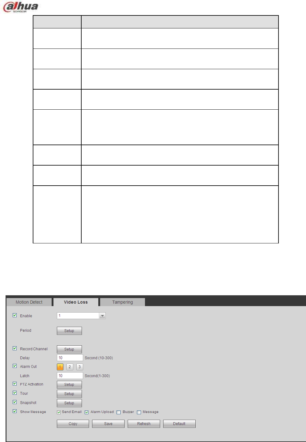
323
Parameter
Function
Buzzer
Check the box here to enable this function. The buzzer beeps
when an alarm occurs.
Alarm upload
System can upload the alarm signal to the centre (Including alarm
centre.
Message
When 3G network connection is OK, system can send out a
message when motion detect occurs.
Send Email
If you enabled this function, System can send out an email to alert
you when an alarm occurs.
Tour
You need to click setup button to select tour channel. System
begins 1-wiindow or multiple-window tour display among the
channel(s) you set to record when an alarm occurs. See Figure
5-59.
PTZ
Activation
Here you can set PTZ movement when alarm occurs. Such as go
to preset X. See Figure 5-58.
Snapshot
Click setup button to select snapshot channel. See Figure 5-60.
Video Matrix
This function is for motion detect only. Check the box here to
enable video matrix function. Right now system supports
one-channel tour function. System takes ―first come and first
serve‖ principle to deal with the activated tour. System will process
the new tour when a new alarm occurs after previous alarm ended.
Otherwise it restores the previous output status before the alarm
activation.
5.8.3.1.2 Video Loss
The video loss interface is shown as in Figure 5-61.
Please note video loss does not support anti-dither, sensitivity, region setup. For rest setups, please refer
to chapter 5.8.3.1.1 motion detect for detailed information.
Figure 5-61
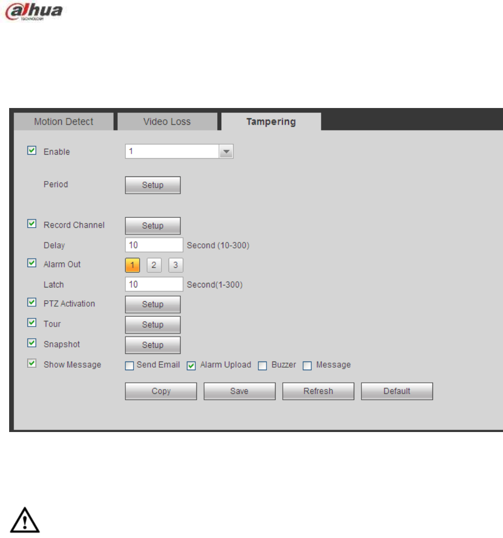
324
5.8.3.1.3 Tampering
The tampering interface is shown as in Figure 5-62.
After analysis video, system can generate a tampering alarm when the detected moving signal reached
the sensitivity you set here.
For detailed setups, please refer to chapter 5.8.3.1.1 motion detect for detailed information.
Figure 5-62
5.8.3.2 IVS (Optional)
Please make sure you are connecting to the smart network camera, otherwise you can not
use IVS function!
From main menu->Setup->Event->IVS, you can go to the IVS interface. It includes four interfaces:
Tripwire/intrusion/object/scene.
5.8.3.2.1 Tripwire
Please make sure you are connecting to the smart network camera, otherwise you can not use
IVS function!
From main menu->Setup->Event->IVS->Tripwire, you can see the following interface. See Figure 5-63.
System generates an alarm once there is any object crossing the tripwire in the specified direction.

325
Figure 5-63
Check the Tripwire box to enable tripwire function.
Select SN (Line1/2/3/4) and direction, and then input customized rule name.
No. and Line1/2/3/4: System supports four tripwires. Each SN stands for one tripwire.
Direction: There are three options: A->B, B->A, both. System can generate an alarm once there is
any object crossing in the specified direction.
Now you can draw a rule. Click Draw rule button and then left click mouse to draw a tripwire. The tripwire
can be a direct line, curve or polygon. Right click mouse to complete. See Figure 5-64.
Figure 5-64
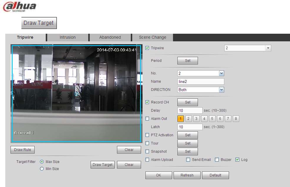
326
Click to draw filter object. See Figure 5-65.
Figure 5-65
Select the blue line and then use mouse to adjust zone size.
Note
Each rule can set two sizes (min size/max size). Once the object is smaller than the min size or larger
than the max size, there is no alarm. Please make sure the max size is larger than the min size.
Click Ok to complete the rule setup.
For detailed setups, please refer to chapter 5.8.3.1.1 motion detect for detailed information.
5.8.3.2.2 Intrusion (Cross warning zone)
Please make sure you are connecting to the smart network camera, otherwise you can not use
IVS function!
From main menu->Setup->Event->IVS->Intrusion, the intrusion interface is shown as below. See Figure
4-102.
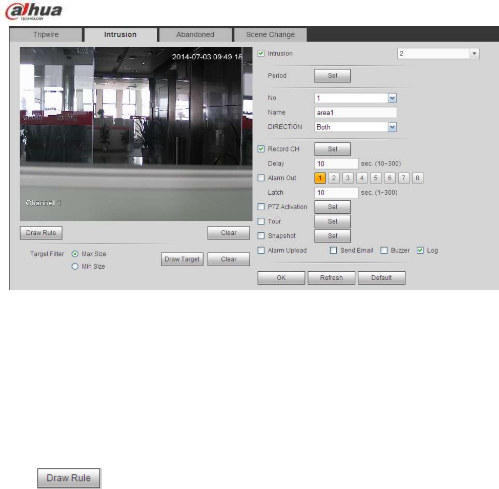
327
Figure 5-66
Check the Intrusion box to enable intrusion function.
Select SN (Area1/2/3/4) and direction, and then input customized rule name.
No. and Area1/2/3/4: System supports four zones. Each SN stands for one zone.
Direction: There are three options: A->B, B->A, both. System can generate an alarm once there is
any object enter/exit (Or both) the zone.
Now you can draw a rule. Left click mouse to draw a line first and then right click mouse to draw another
line until you draw a rectangle, you can right click mouse to exit.
Click Ok to complete the rule setup.
Click to draw the zone. See Figure 5-67.
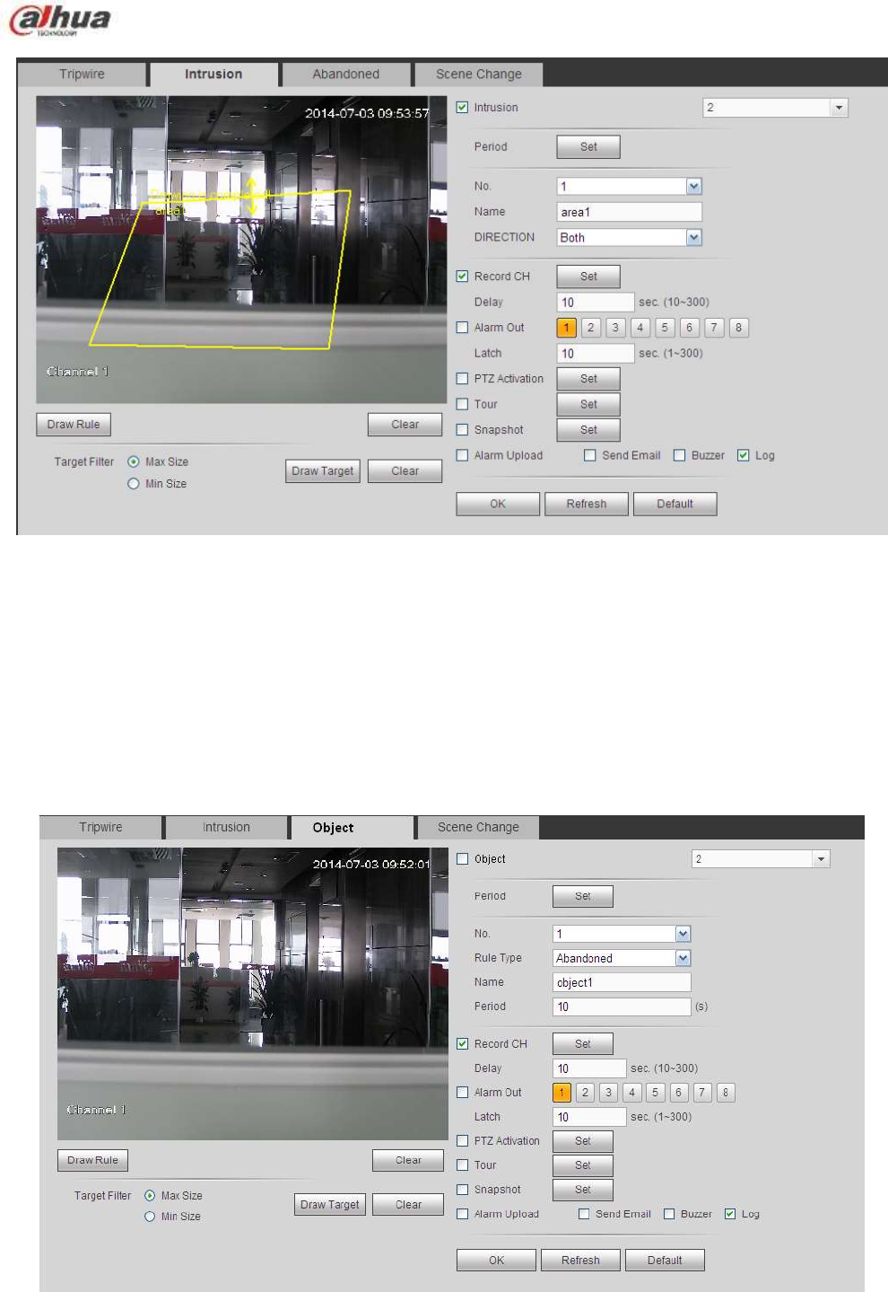
328
Figure 5-67
For detailed setups, please refer to chapter 5.8.3.1.1 motion detect for detailed information.
5.8.3.2.3 Object Detect
Please make sure you are connecting to the smart network camera, otherwise you can not use
IVS function!
For the same channel,the object detect and the intrusion can not be valid at the same time.
From main menu->Setup->Event->IVS->Object, the object interface is shown as below. See Figure 5-68.
Figure 5-68
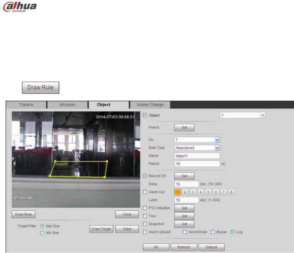
329
Check the Object box to enable object detect function.
Select SN (object1/2/3/4) and rule type, and then input customized rule name.
No. and Object1/2/3/4: System supports four zones. Each SN stands for one zone.
Rule type: Please select from the dropdown list. There are two types: Missing object
detect/abandoned object detect.
Period: It refers to the object in/out the zone time.
Click to draw the rule. See Figure 5-69.
Figure 5-69
Now you can draw a rule. Left click mouse to draw a line, until you draw a rectangle, you can right click
mouse.
Click Ok to complete the rule setup.
For detailed setups, please refer to chapter 5.8.3.1.1 motion detect for detailed information.
5.8.3.2.4 Change Scene
Please make sure you are connecting to the smart network camera, otherwise you can not use
IVS function!
When the detected scene changes ,,the system can generate an alarm. From main
menu->Setup->Event->IVS->Change scene, the interface is shown as in Figure 5-70.
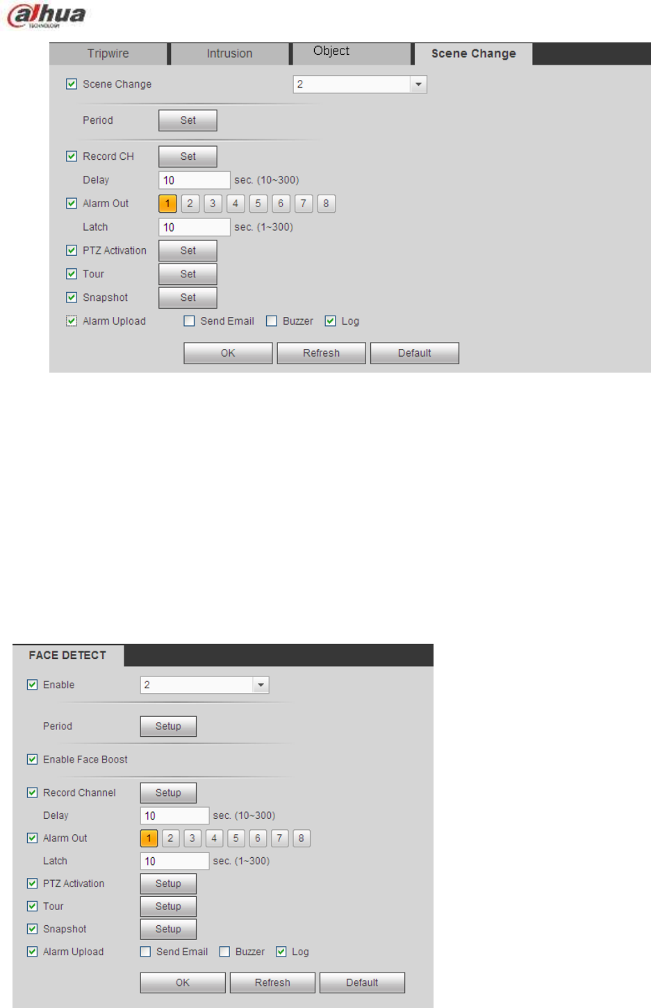
330
Figure 5-70
For detailed setups, please refer to chapter 5.8.3.1.1 motion detect for detailed information.
5.8.3.3 Face Detect (Optional)
Please make sure you are connecting to the smart network camera, otherwise you can not use
IVS function!
When camera detects human face, system can generate an alarm.
From main menu->Setup->Event->Face detect, the interface is shown as in Figure 5-71.
Enable face boost: Check the box here, system can enhance the human face display pane.
Sensitivity: System supports 6 levels. The sixth level has the highest sensitivity.
For detailed setups, please refer to chapter 5.8.3.1.1.
Figure 5-71
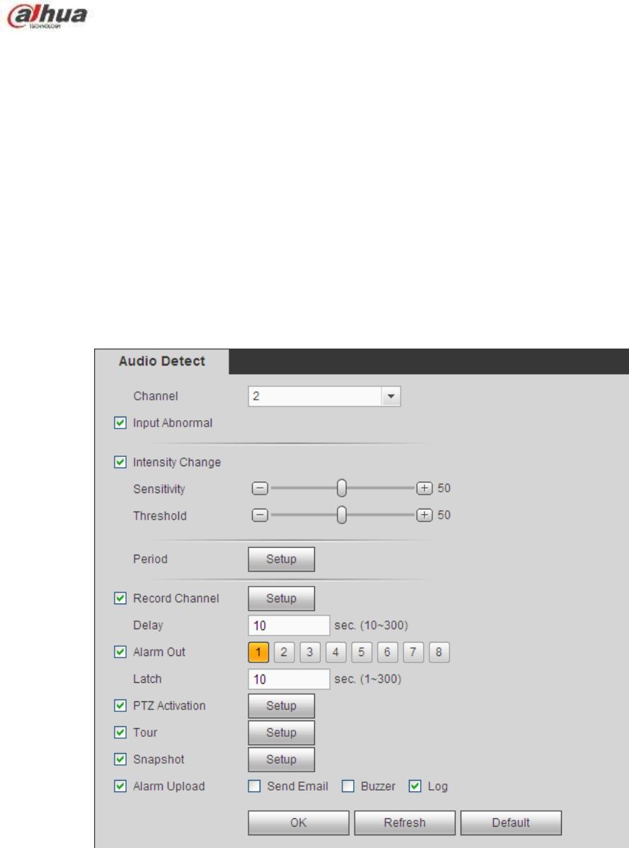
331
5.8.3.4 Audio Detect (Optional)
Please make sure you are connecting to the smart network camera, otherwise you can not use
IVS function!
System can generate an alarm once it detect the audio input is abnormal or audio volume changes.
From main menu->Setup->Event->Audio detect, you can see an interface shown as in Figure 5-72.
Input abnormal: Check the box here, system can generate an alarm once the audio input is
abnormal.
Intensity change: Check the box here, system can generate an alarm once the audio volume
becomes strong.
Sensitivity: It refers to the audio recognition sensitivity. The higher the value is, the higher the
sensitivity is.
Threshold: It is to set intensity change threshold. The smaller the value is, the higher the sensitivity
is.
For detailed setups, please refer to chapter 5.8.3.1.1 motion detect for detailed information.
Figure 5-72
5.8.3.5 Alarm
Before operation, please make sure you have properly connected alarm devices such as buzzer. The
input mode includes local alarm and network alarm.
5.8.3.5.1 Local Alarm
The local alarm interface is shown as in Figure 5-73. It refers to alarm from the local device.
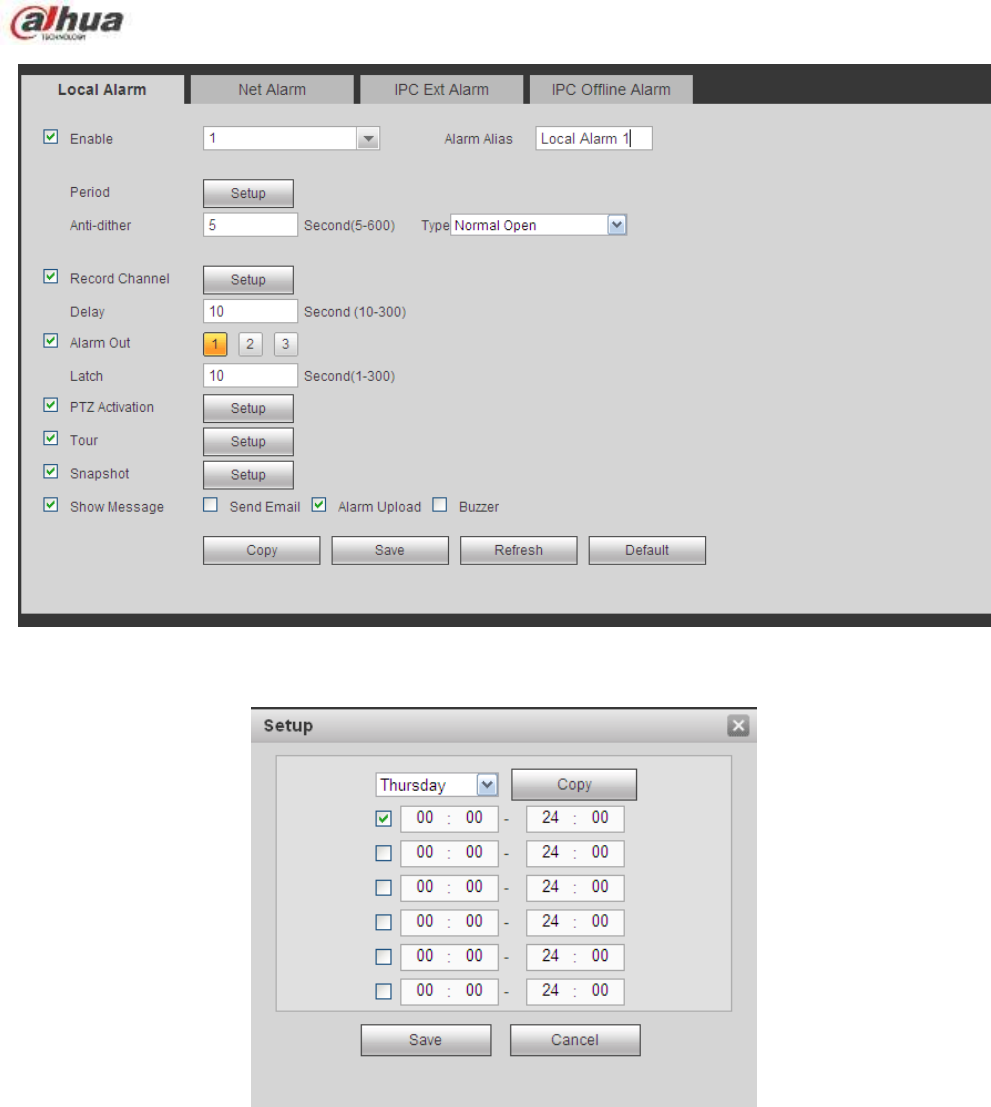
332
Figure 5-73
Figure 5-74
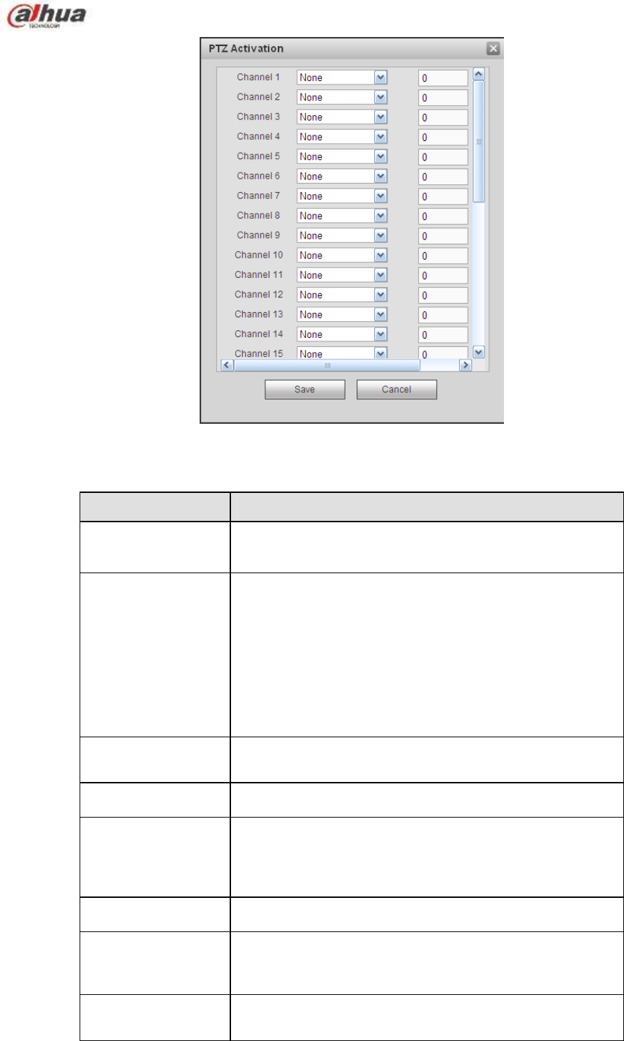
333
Figure 5-75
Please refer to the following sheet for detailed information.
Parameter
Function
Enable
You need to check the box to enable this function.
Please select a channel from the dropdown list.
Period
This function becomes activated in the specified periods.
There are six periods in one day. Please draw a circle to
enable corresponding period.
Select date. If you do not select, current setup applies to
today only. You can select all week column to apply to the
whole week.
Click OK button, system goes back to local alarm
interface, please click save button to exit.
Anti-dither
System only memorizes one event during the anti-dither
period. The value ranges from 5s to 600s.
Sensor type
There are two options: NO/NC.
Record channel
System auto activates motion detection channel(s) to
record once an alarm occurs. Please note you need to set
alarm record period and go to Storage-> Schedule to set
current channel as schedule record.
Record Delay
System can delay the record for specified time after alarm
ended. The value ranges from 10s to 300s.
Alarm out
Enable alarm activation function. You need to select alarm
output port so that system can activate corresponding
alarm device when an alarm occurs.
Latch
System can delay the alarm output for specified time after
an alarm ended. The value ranges from 1s to 300s.
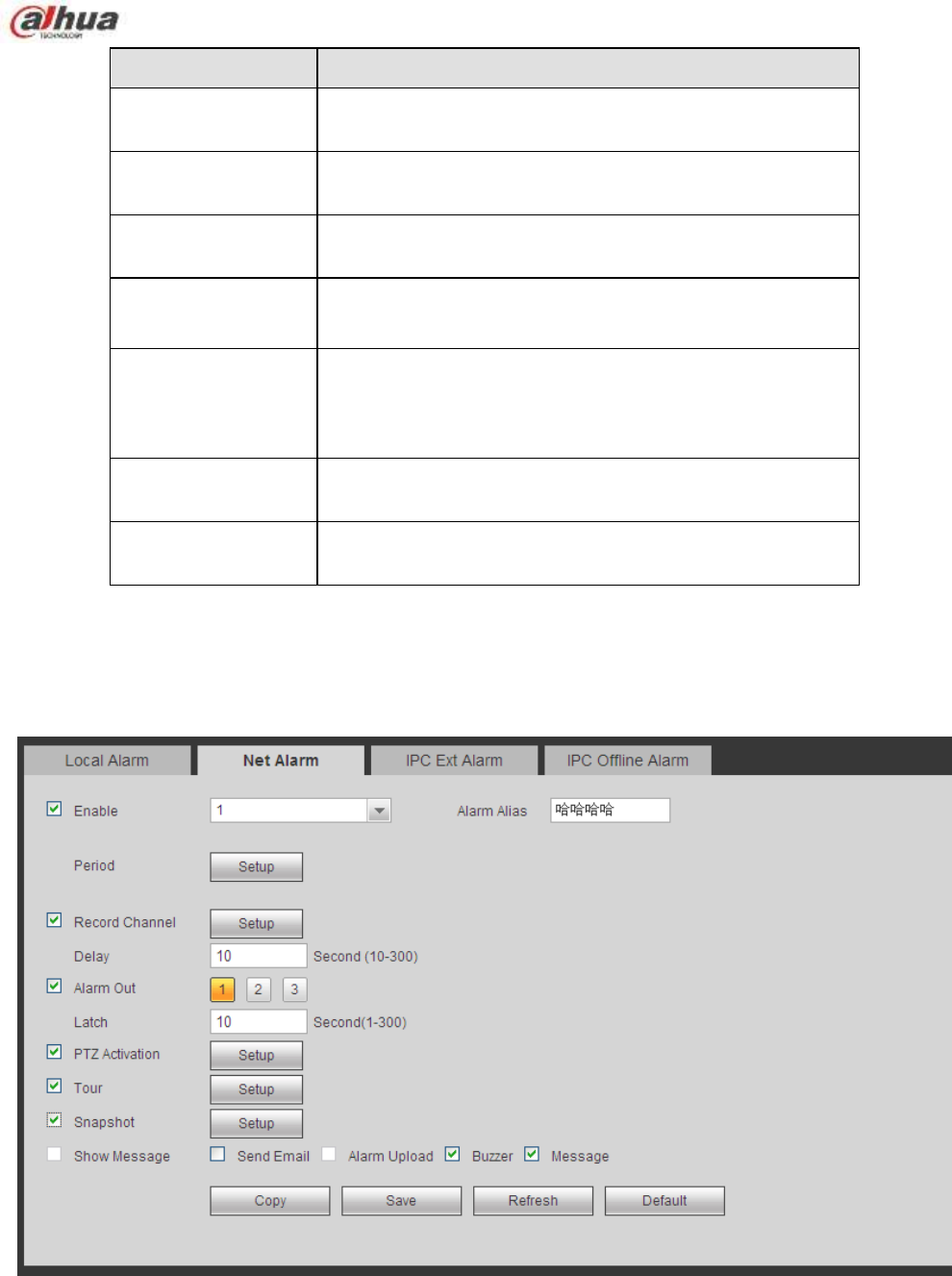
334
Parameter
Function
Show message
System can pop up a message to alarm you in the local
host screen if you enabled this function.
Buzzer
Check the box here to enable this function. The buzzer
beeps when an alarm occurs.
Alarm upload
System can upload the alarm signal to the centre
(Including alarm centre).
Send Email
If you enabled this function, System can send out an email
to alert you when an alarm occurs.
Tour
You need to click setup button to select tour channel.
System begins 1-wiindow or multiple-window tour display
among the channel(s) you set to record when an alarm
occurs. See Figure 5-59.
PTZ Activation
Here you can set PTZ movement when alarm occurs.
Such as go to preset X. See Figure 5-75.
Snapshot
Click setup button to select snapshot channel. See Figure
5-60.
5.8.3.5.2 Net Alarm
The network alarm interface is shown as in Figure 5-76.
Network alarm refers to the alarm signal from the network. System does not anti-dither and sensor type
setup. For setup information, please refer to chapter 5.8.3.5.1.
Figure 5-76
5.8.3.5.3 IPC external alarm
The IPC external alarm interface is shown as in Figure 5-77.
Network alarm refers to the alarm signal from the network. System does not anti-dither and sensor type
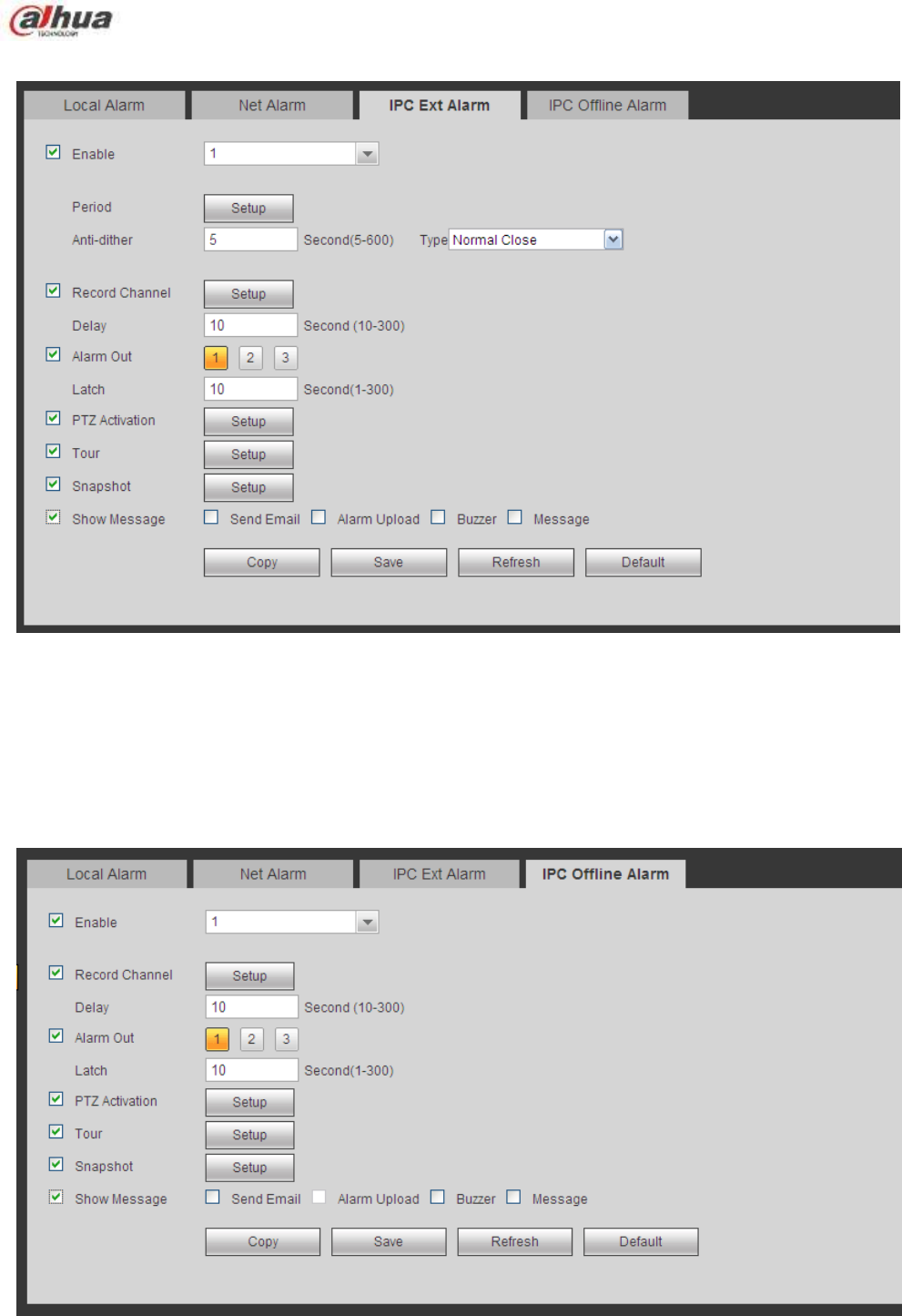
335
setup. For setup information, please refer to chapter 5.8.3.5.1.
Figure 5-77
5.8.3.5.4 IPC Offline Alarm
The IPC offline alarm interface is shown as in Figure 5-78.
System can generate an alarm once the network camera is offline. For setup information, please refer to
chapter 5.8.3.5.1.
Figure 5-78
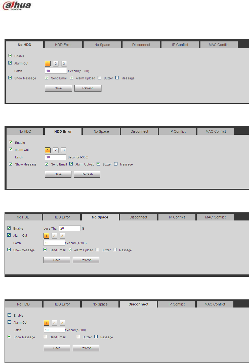
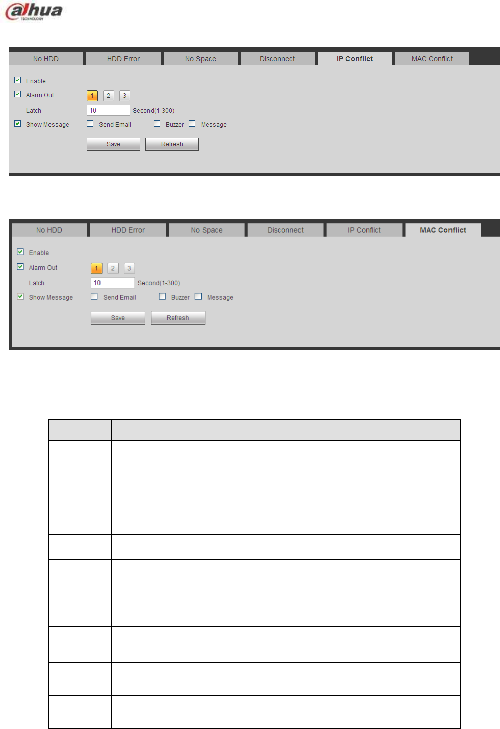
337
Figure 5-83
Figure 5-84
Please refer to the following sheet for detailed information.
Parameter
Function
Event
Type
The abnormal events include: No disk, disk error, disk no space, net
disconnection, IP conflict and MAC conflict.
You can set one or more items here.
Less than: You can set the minimum percentage value here (For disk
not space only). The device can alarm when capacity is not sufficient.
You need to draw a circle to enable this function.
Enable
Check the box here to enable selected function.
Alarm Out
Please select corresponding alarm output channel when an alarm
occurs. You need to check the box to enable this function.
Latch
The alarm output can delay for the specified time after an alarm stops.
The value ranges from 1s to 300s.
Show
message
System can pop up a message to alarm you in the local host screen if
you enabled this function.
Alarm
upload
System can upload the alarm signal to the centre (Including alarm
centre.
Send
Email
If you enabled this function, System can send out an email to alert you
when an alarm occurs.
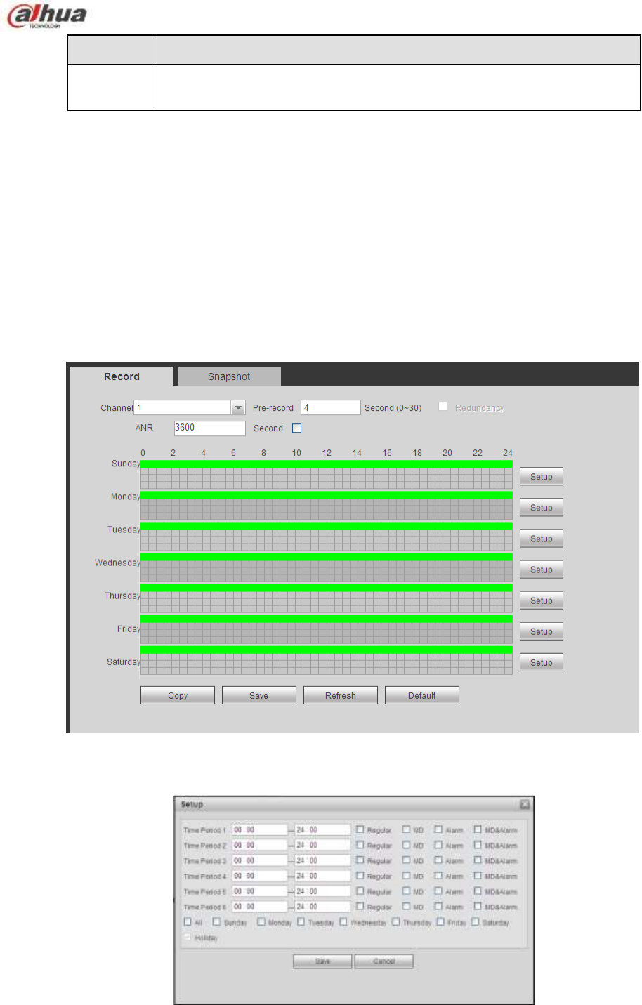
338
Parameter
Function
Buzzer
Check the box here to enable this function. The buzzer beeps when an
alarm occurs.
5.8.4 Storage
5.8.4.1 Schedule
In this interfaces, you can add or remove the schedule record setup. See Figure 5-85.
There are four record modes: general (auto), motion detect, alarm and MD&alarm. There are six periods
in one day.
You can view the current time period setup from the color bar.
Green color stands for the general record/snapshot.
Yellow color stands for the motion detect record/snapshot..
Red color stands for the alarm record/snapshot.
Blue color stands for MD&alarm record/snapshot.
Figure 5-85
Figure 5-86
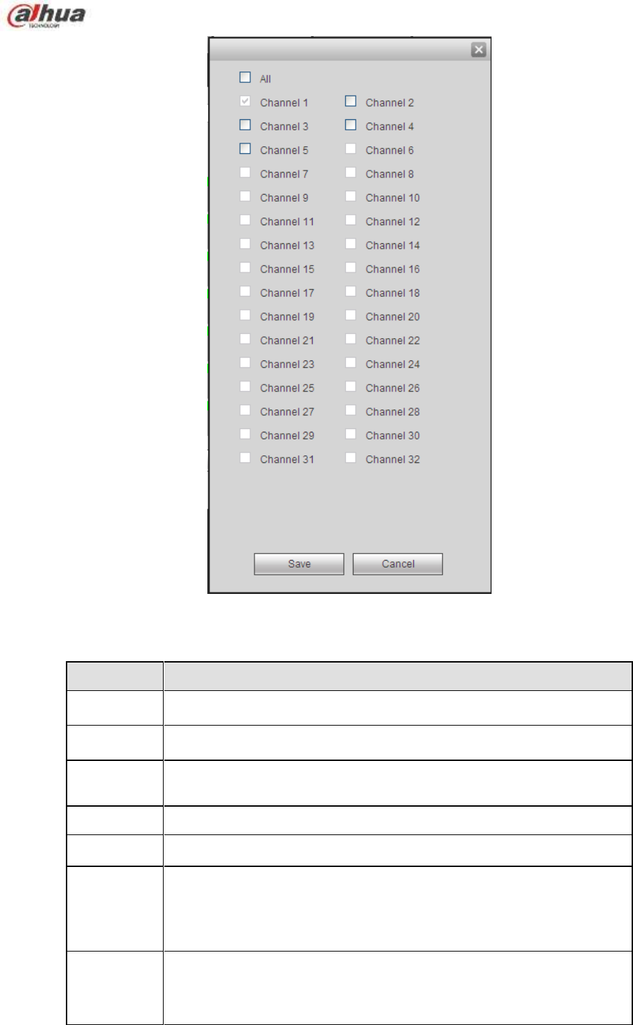
339
Figure 5-87
Please refer to the following sheet for detailed information.
Parameter
Function
Channel
Please select a channel from the dropdown list.
Pre-record
Please input pre-record time here. The value ranges from 0 to 30.
Redundancy
Check the box here to enable redundancy function. Please note this
function is null if there is only one HDD.
Snapshot
Check the box here to enable snapshot function.
Holiday
Check the box here to enable holiday function.
Setup
Click the Setup button, you can set record period. See Figure 5-86.
There are six periods in one day. If you do not check the date at the
bottom of the interface, current setup is for today only.
Please click Save button and then exit.
Copy
Copy function allows you to copy one channel setup to another. After
setting in channel, click Copy button, you can go to interface Figure
5-87. You can see current channel name is grey such as channel 1.
Now you can select the channel you want to paste such as channel
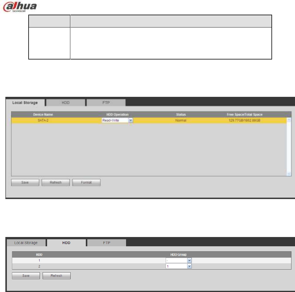
340
Parameter
Function
5/6/7. If you want to save current setup of channel 1 to all channels,
you can click the first box ―ALL‖. Click the OK button to save current
copy setup. Click the OK button in the Encode interface, the copy
function succeeded.
5.8.4.2 HDD Manager
5.8.4.2.1 Local Storage
The local interface is shown as in Figure 5-88. Here you can see HDD information. You can also operate
the read-only, read-write, redundancy (if there are more than on HDD) and format operation.
Figure 5-88
5.8.4.2.2 HDD
The HDD interface is to set HDD group. See Figure 5-89.
Figure 5-89
5.8.4.2.3 FTP
The FTP interface is to set FTP information. See Figure 5-90.
Please set the FTP as your remote storage location. System can save record file or snapshot picture to
the FTP once the network is offline or malfunction.
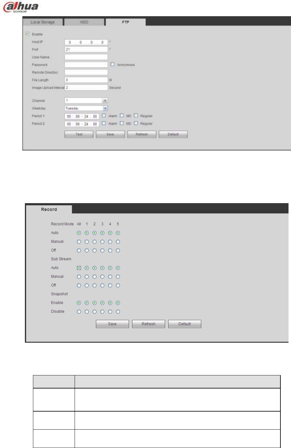
341
Figure 5-90
5.8.4.3 Record Control
The interface is shown as in Figure 5-91.
Figure 5-91
Please refer to the following sheet for detailed information.
Parameter
Function
Channel
Here you can view channel number.
The number displayed here is the max channel amount of your
device.
Status
There are three statuses: schedule, manual and stop.
Schedule
System enables auto record function as you set in record schedule
setup (general, motion detect and alarm).
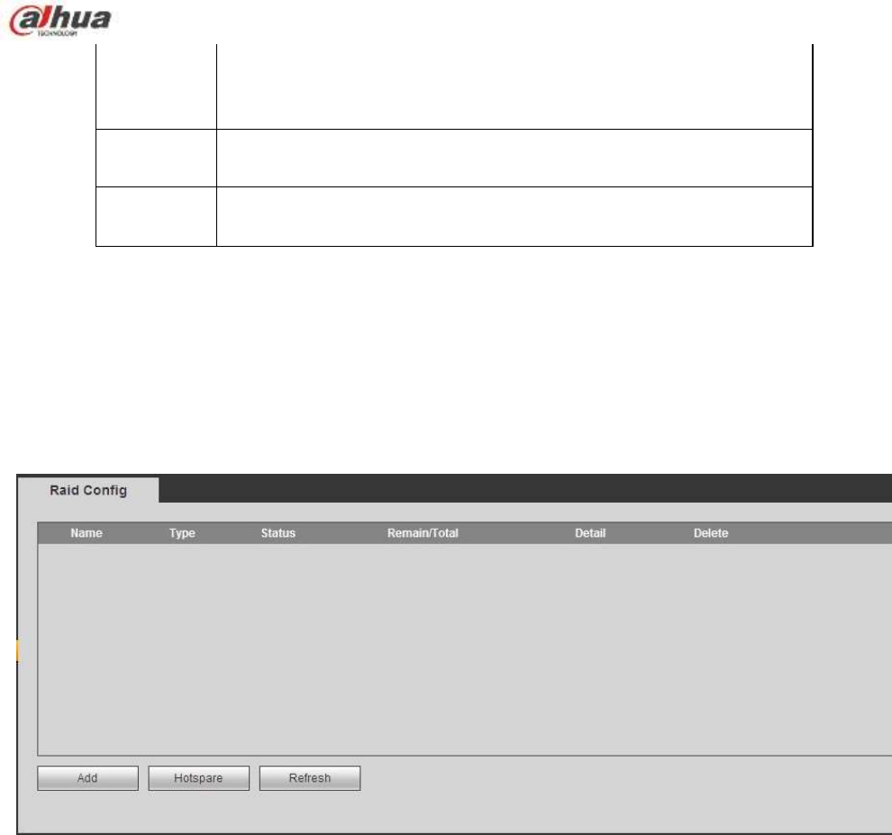
342
Manual
It has the highest priority.
Enable corresponding channel to record no matter what period
applied in the record setup.
Stop
Stop current channel record no matter what period applied in the
record setup.
Start all/
stop all
Check the corresponding All button, you can enable or disable all
channels record.
5.8.4.4 RAID Manager
Important
Please make sure your purchased product support the RAID function, otherwise you can not see
the following interface.
5.8.4.4.1 RAID Config
It is for you to manage RAID HDD. It can display RAID name, type, free space, total space, status and etc.
Here you can add/delete RAID HDD.
Click Add button to select RAID type and then select HDDs, click OK button to add. See Figure 5-92.
Figure 5-92
5.8.4.4.2 Hotspare disks
In Figure 5-92, click hotspare button, you can add the hot spare HDD. See Figure 5-93. The type includes
two options:
Global: It is global hotspare disk. When any RAID becomes degrading, it can replace and build the
RAID.
Local: It is local hotspare disk. When the specified RAID becomes degrading, it can replace and build
the RAID.
Select a hot spare device and then click Delete button. Click Apply button to delete.
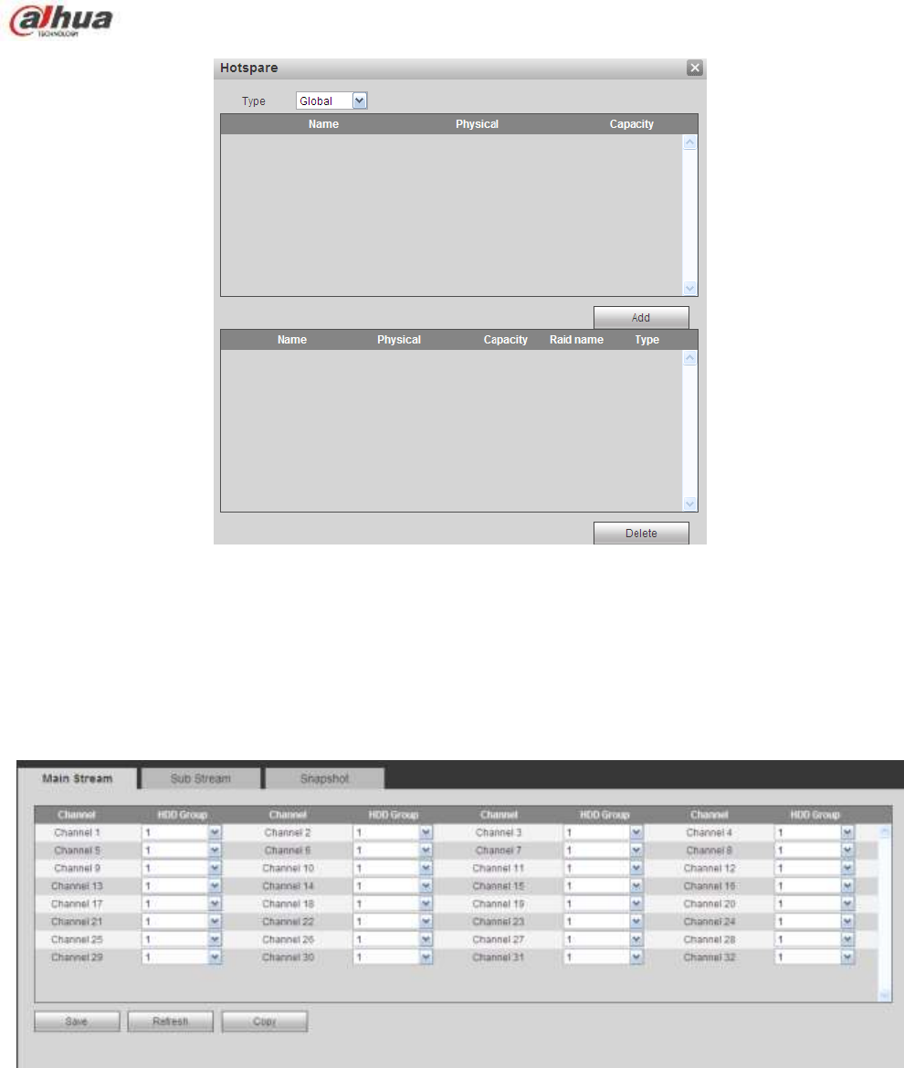
343
Figure 5-93
5.8.4.5 Storage
5.8.4.5.1 Main Stream
The main stream interface is shown as in Figure 5-94. Here you can set corresponding HDD group to
save main stream.
Figure 5-94
5.8.4.5.2 Sub Stream
The sub stream interface is shown as in Figure 5-95.
Here you can set corresponding HDD group to save sub stream.
344
Figure 5-95
5.8.4.5.3 Snapshot
The snapshot interface is shown as in Figure 5-96. Here you can set corresponding HDD group to save
snapshot picture.
Figure 5-96
5.8.5 Setting
5.8.5.1 General
The general interface includes general, date/time and holiday setup.
5.8.5.1.1 General
The general interface is shown as in Figure 5-97.
Figure 5-97
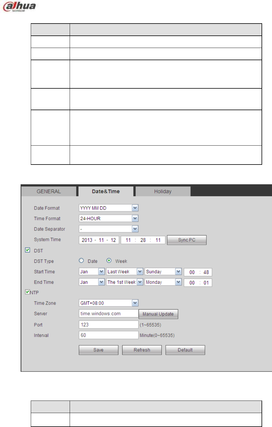
345
Please refer to the following sheet for detailed information.
Parameter
Function
Device ID
It is to set device name.
Device No.
It is device channel number.
Language
You can select the language from the dropdown list.
Please note the device needs to reboot to get the modification
activated.
Video
Standard
This is to display video standard such as PAL.
HDD full
Here is for you to select working mode when hard disk is full. There
are two options: stop recording or rewrite. If current working HDD is
overwritten or the current HDD is full while the next HDD is no empty,
then system stops recording, If the current HDD is full and then next
HDD is not empty, then system overwrites the previous files.
Pack
duration
Here is for you to specify record duration. The value ranges from 1 to
120 minutes. Default value is 60 minutes.
5.8.5.1.2 Date and time
The date and time interface is shown as in Figure 5-98
Figure 5-98
Please refer to the following sheet for detailed information.
Parameter
Function
Date format
Here you can select date format from the dropdown list.

346
Time
Format
There are two options: 24-H and 12-H.
Time zone
The time zone of the device.
System
time
It is to set system time. It becomes valid after you set.
Sync PC
You can click this button to save the system time as your PC current
time.
DST
Here you can set day night save time begin time and end time. You
can set according to the date format or according to the week format.
NTP
You can check the box to enable NTP function.
NTP server
You can set the time server address.
Port
It is to set the time server port.
Interval
It is to set the sync periods between the device and the time server.
5.8.5.1.3 Holiday Setup
Holiday setup interface is shown as in Figure 5-99.
Here you can click Add holidays box to add a new holiday and then click Save button to save.
Figure 5-99
5.8.5.2 Account
Note:
For the character in the following user name or the user group name, system max supports 6-digits.
The space in the front or at the end of the string is null. The valid string includes: character, number,
and underline.
The user amount default setup is 64 and the group amount default setup is 20. The factory default
setup includes two levels: user and admin. You can set the corresponding group and then set the
rights for the respective user in the specified groups.
User management adopts group/user modes. The user name and the group name shall be unique.
One user shall be included in only one group.
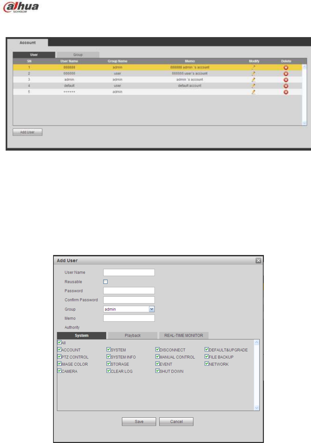
347
5.8.5.2.1 User name
In this interface you can add/remove user and modify user name. See Figure 5-100.
Figure 5-100
Add user: It is to add a name to group and set the user rights. See Figure 5-101.
There are three default users: admin/888888 and hidden user ―default‖.
Hidden user ―default‖ is for system interior use only and can not be deleted. When there is no login user,
hidden user ―default‖ automatically login. You can set some rights such as monitor for this user so that
you can view some channel view without login.
Here you can input the user name and password and then select one group for current user.
Please note the user rights shall not exceed the group right setup.
For convenient setup, please make sure the general user has the lower rights setup than the admin.
Figure 5-101
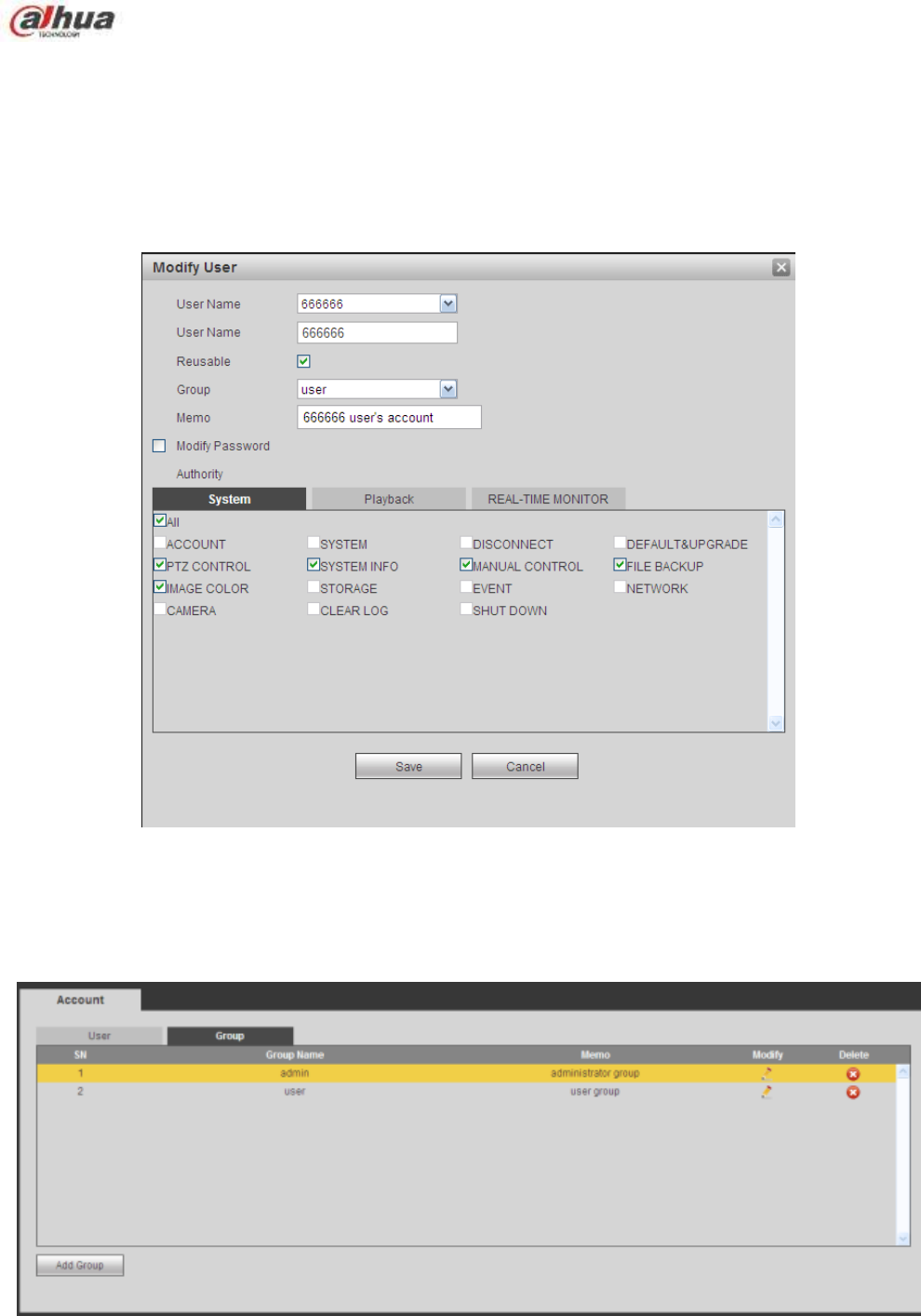
348
Modify user
It is to modify the user property, belonging group, password and rights. See Figure 5-102.
Modify password
It is to modify the user password. You need to input the old password and then input the new password
twice to confirm the new setup. Please click the OK button to save.
Please note, the password ranges from 1-digit to 6-digit. It shall include the number only. For the user of
the account rights, he can modify the password of other users.
Figure 5-102
5.8.5.2.2 Group
The group management interface can add/remove group, modify group password and etc.
The interface is shown as in Figure 5-103.
Figure 5-103
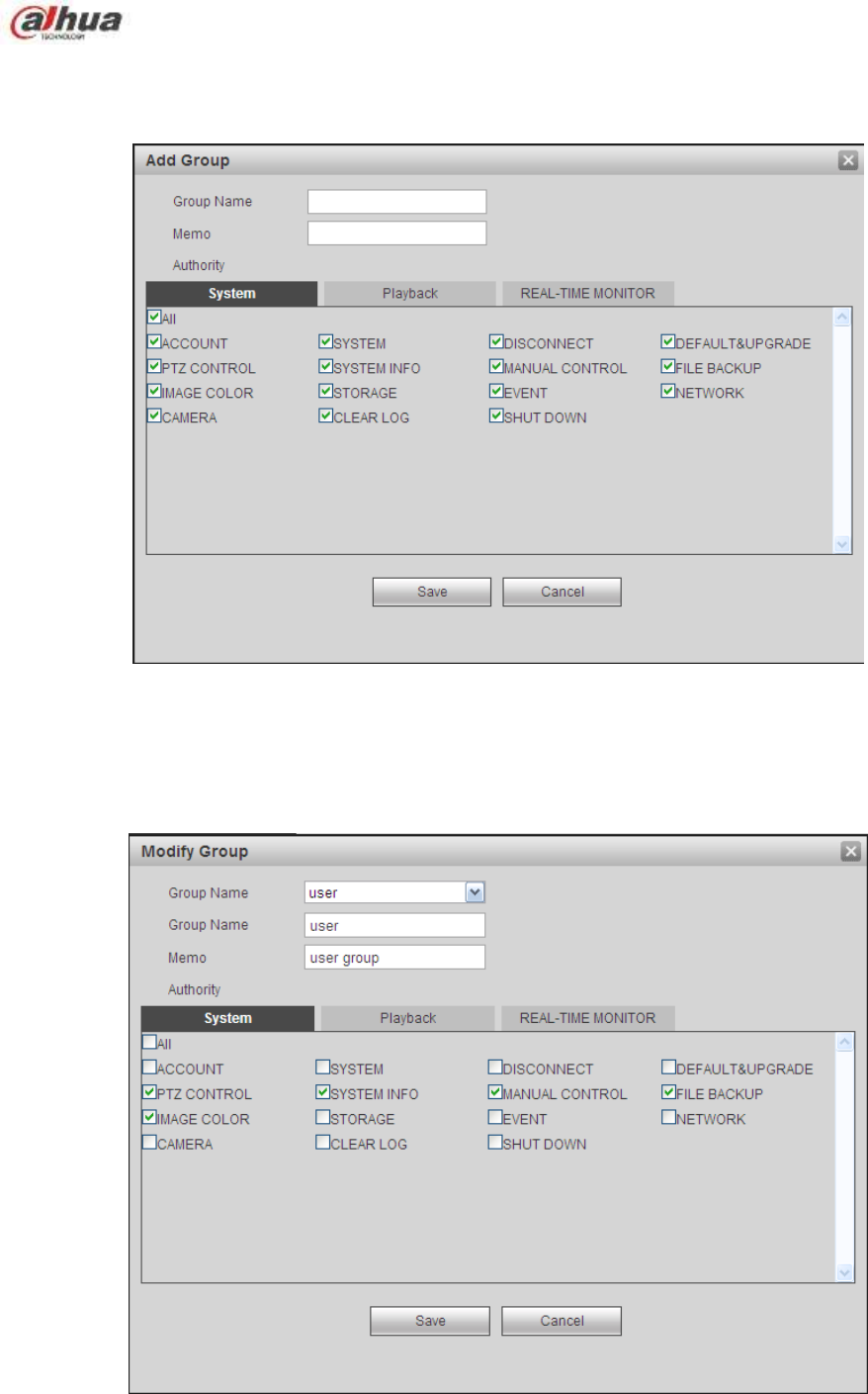
349
Add group: It is to add group and set its corresponding rights. See Figure 5-104.
Please input the group name and then check the box to select the corresponding rights. It includes:
shutdown/reboot device, live view, record control, PTZ control and etc.
Figure 5-104
Modify group
Click the modify group button, you can see an interface is shown as in Figure 5-105.
Here you can modify group information such as remarks and rights.
Figure 5-105
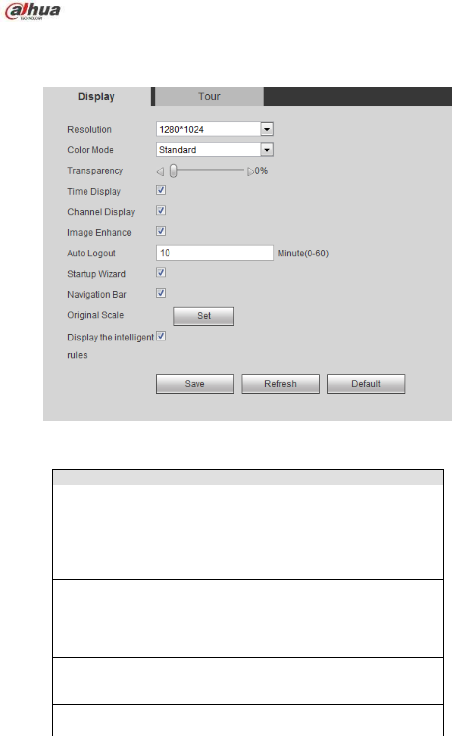
350
5.8.5.3 Display
Display interface includes GUI, TV adjust, Tour and zero-channel encoding.
5.8.5.3.1 Display
Here you can set background color and transparency level. See Figure 5-106.
Figure 5-106
Please refer to the following sheet for detailed information.
Parameter
Function
Resolution
There are four options: 1920×1080, 1280×1024(default),
1280×720, 1024×768. Please note the system needs to reboot to
activate current setup.
Color mode
Please select from the dropdown list.
Transparency
Here is for you to adjust transparency. The value ranges from 128
to 255.
Time
title/channel
title
Check the box here, you can view system time and channel
number on the monitor video.
Image
enhance
Check the box; you can optimize the margin of the preview video.
Startup
wizard
Once you check the box here, system will go to the startup wizard
directly when the system restarts the next time. Otherwise, it will go
to the login interface.
Navigation
bar
Check the box here, system displays the navigation bar on the
interface.
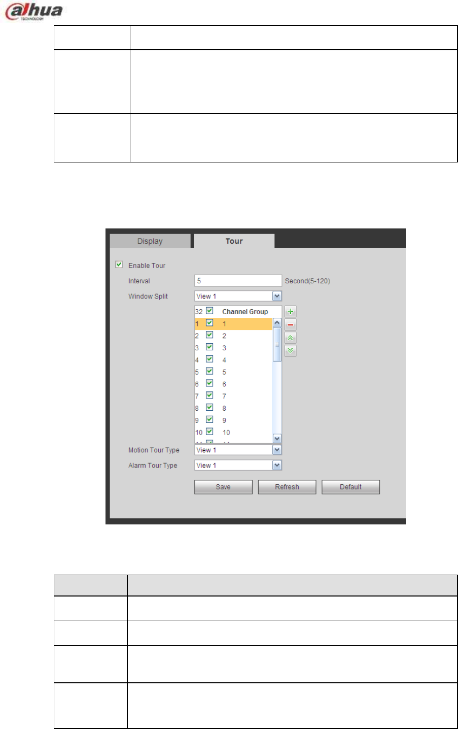
351
Original scale
Click the Set button to select a channel, it can restore original scale.
Auto logout
Here is for you to set auto logout interval once login user remains
inactive for a specified time. Value ranges from 0 to 60 minutes. 0
means there is no standby time. After the auto logout, the user
needs to input user name and password to login again.
Display
intelligent
rule(s)
Check the box to enable IVS function, system can display IVS rule
on the preview interface.
5.8.5.3.2 Tour
The tour interface is shown as in Figure 5-107. Here you can set tour interval, split mode, motion detect
tour and alarm tour mode.
Figure 5-107
Please refer to the following sheet for detailed information.
Parameter
Function
Enable tour
Check the box here to enable tour function.
Interval
Here is for you to adjust transparency. The value ranges from 5 to
120s. The default setup is 5s.
Split
Here you can set window mode and channel group. System can
support 1/4/8/9/16/25/36-window according to device channel
amount.
Motion
tour/Alarm
tour
Here you can set motion detect tour/alarm tour window mode.
System supports 1/8-window now.
5.8.5.4 Alarm Out
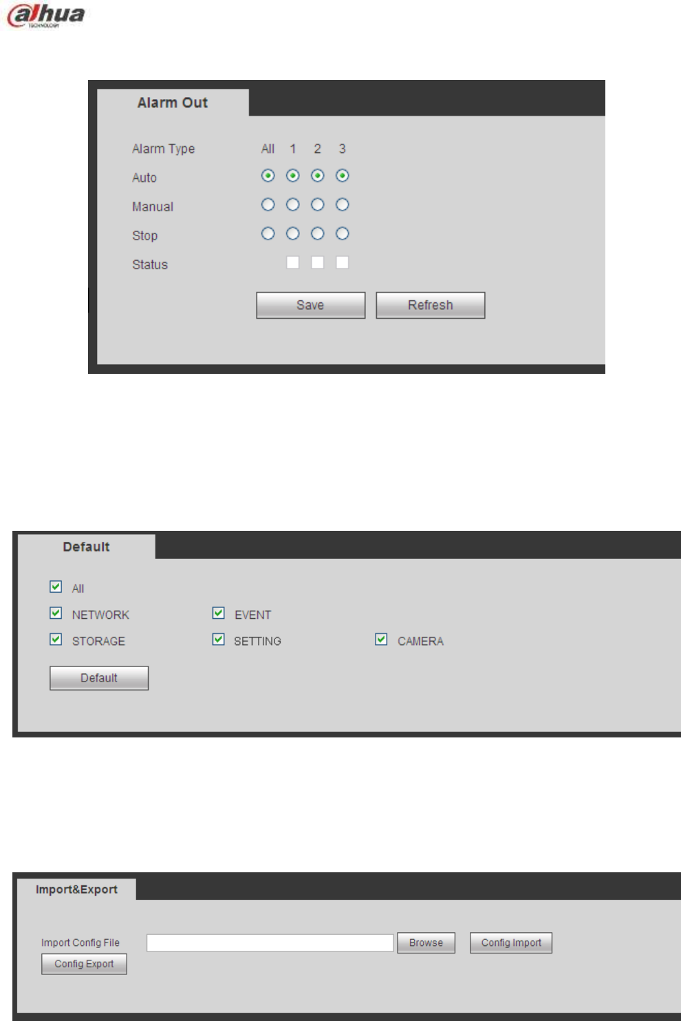
352
The alarm output interface is shown as below. See Figure 5-108
Here you can set alarm output mode: auto/manual/stop.
Figure 5-108
5.8.5.5 Default
The default setup interface is shown as in Figure 5-109.
Here you can select Network/Event/Storage/Setting/Camera. Or you can check the All box to select all
items.
Figure 5-109
5.8.5.6 Import/Export
The interface is shown as in Figure 5-110. This interface is for you to export or import the configuration
files.
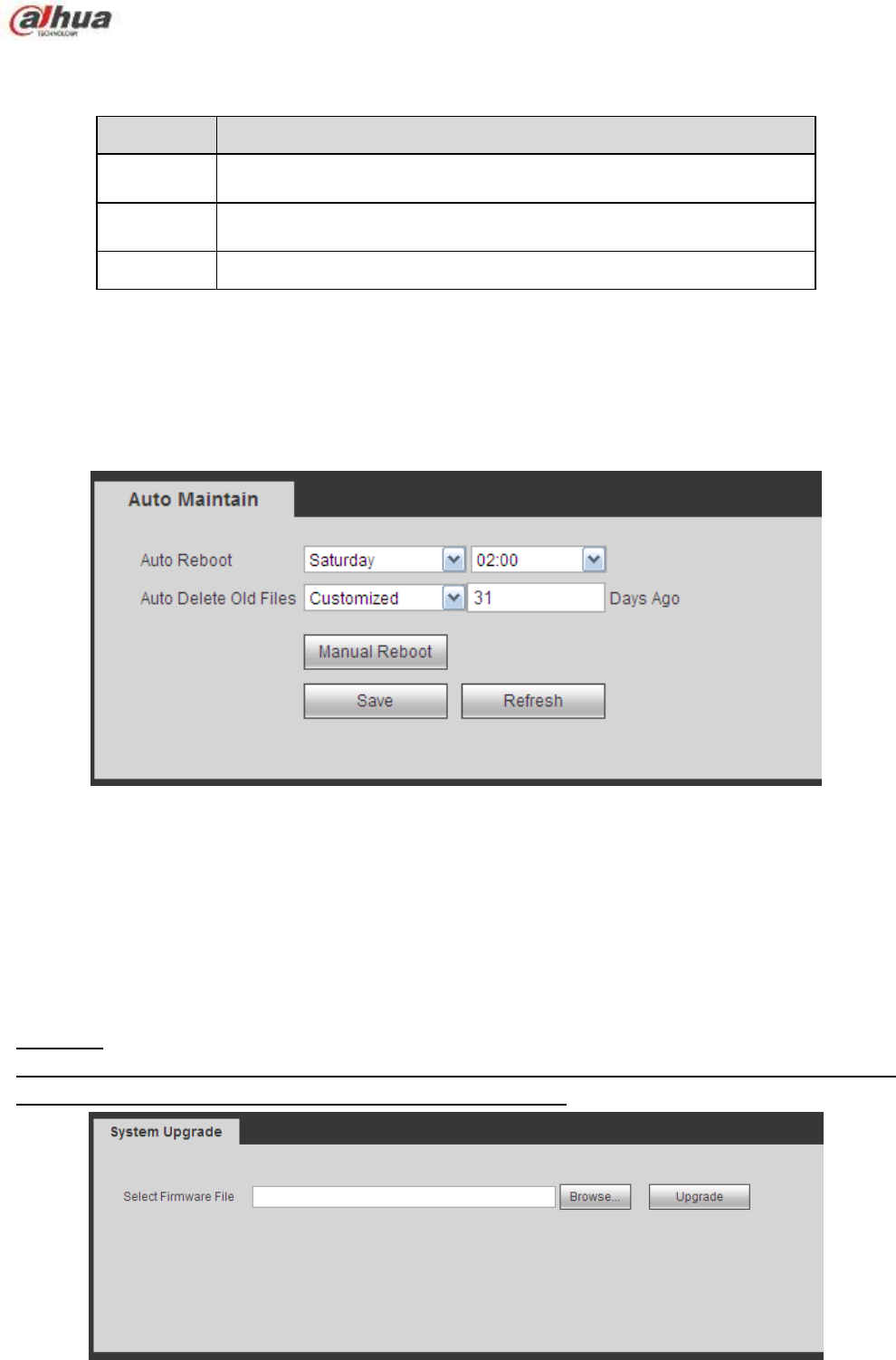
353
Figure 5-110
Please refer to the following sheet for detailed information.
Parameter
Function
Browse
Click to select import file.
Import
It is to import the local setup files to the system.
Export
It is to export the corresponding WEB setup to your local PC.
5.8.5.7 Auto maintain
The auto maintain interface is shown as in Figure 5-111.
Here you can select auto reboot and auto delete old files interval from the dropdown list.
If you want to use the auto delete old files function, you need to set the file period.
Click Manual reboot button, you can restart device manually.
Figure 5-111
5.8.5.8 Upgrade
The upgrade interface is shown as in Figure 5-112.
Please select the upgrade file and then click the update button to begin update. Please note the file name
shall be as *.bin. During the upgrade process, do not unplug the power cable, network cable, or shutdown
the device.
Important
Improper upgrade program may result in device malfunction! Please make sure the operation is
operated under the supervision of the professional engineer!
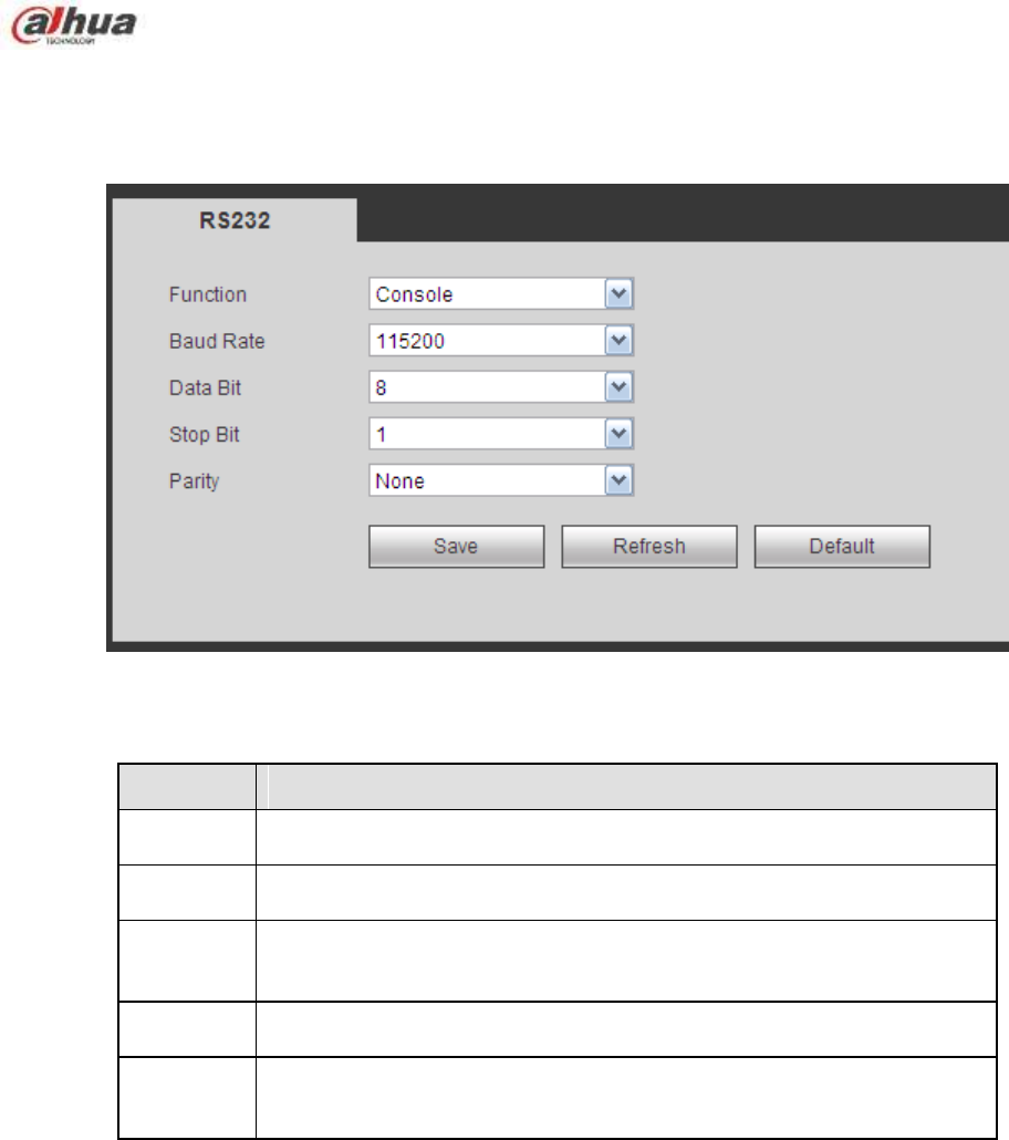
354
Figure 5-112
5.8.5.9 RS232
The RS232 interface is shown as in Figure 5-113.
Figure 5-113
Please refer to the following sheet for detailed information.
Parameter
Function
Protocol
Select the corresponding dome protocol.
Default setup is console.
Baud Rate
Select the baud rate.
Default setup is 115200.
Data Bit
The value ranges from 5 to 8.
Default setup is 8.
Stop bit
There are two options: 1/2.
Default setup is 1.
Parity
There are five options: none/odd/even/space/mark.
Default setup is none.
5.8.5.10 PTZ
The PTZ interface is shown as in Figure 5-114 (Local) and Figure 5-115 (Remote).
Before setup, please check the following connections are right:
PTZ and decoder connection is right. Decoder address setup is right.
Decoder A (B) line connects with NVR A (B) line.
Click Save button after you complete setup, you can go back to the monitor interface to control speed
dome.
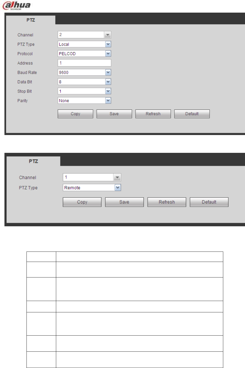
355
Figure 5-114
Figure 5-115
Please refer to the following sheet for detailed information.
Parameter
Function
Channel
Select speed dome connected channel.
PTZ Type
There are two options: local/remote.
Please select remote type if you are connecting to the network PTZ.
Please select local type if you are using RS485 to the PTZ camera.
Protocol
Select the corresponding dome protocol such as PELCOD.
Address
Set corresponding dome address. Default value is 1. Please note
your setup here shall comply with your dome address; otherwise
you can not control the speed dome.
Baud
Rate
Select the dome baud rate. Default setup is 9600.
Data Bit
The value ranges from 5 to 8. Default setup is 8. Please set according
to the speed dome dial switch setup.
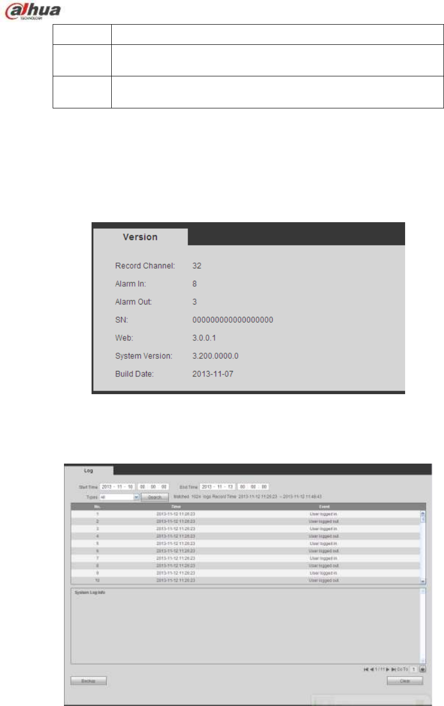
356
Parameter
Function
Stop bit
The value ranges from 1 to 2. Default setup is 1. Please set according
to the speed dome dial switch setup.
Parity
The options include non/odd/even/space/null. Default setup is none.
Please set according to the speed dome dial switch setup.
5.9 Information
5.9.1 Version
The version interface is shown as in Figure 5-116.
Here you can view record channel, alarm input/output information, software version, release date and etc.
Please note the following information is for reference only.
Figure 5-116
5.9.2 Log
Here you can view system log. See Figure 5-117.
Figure 5-117
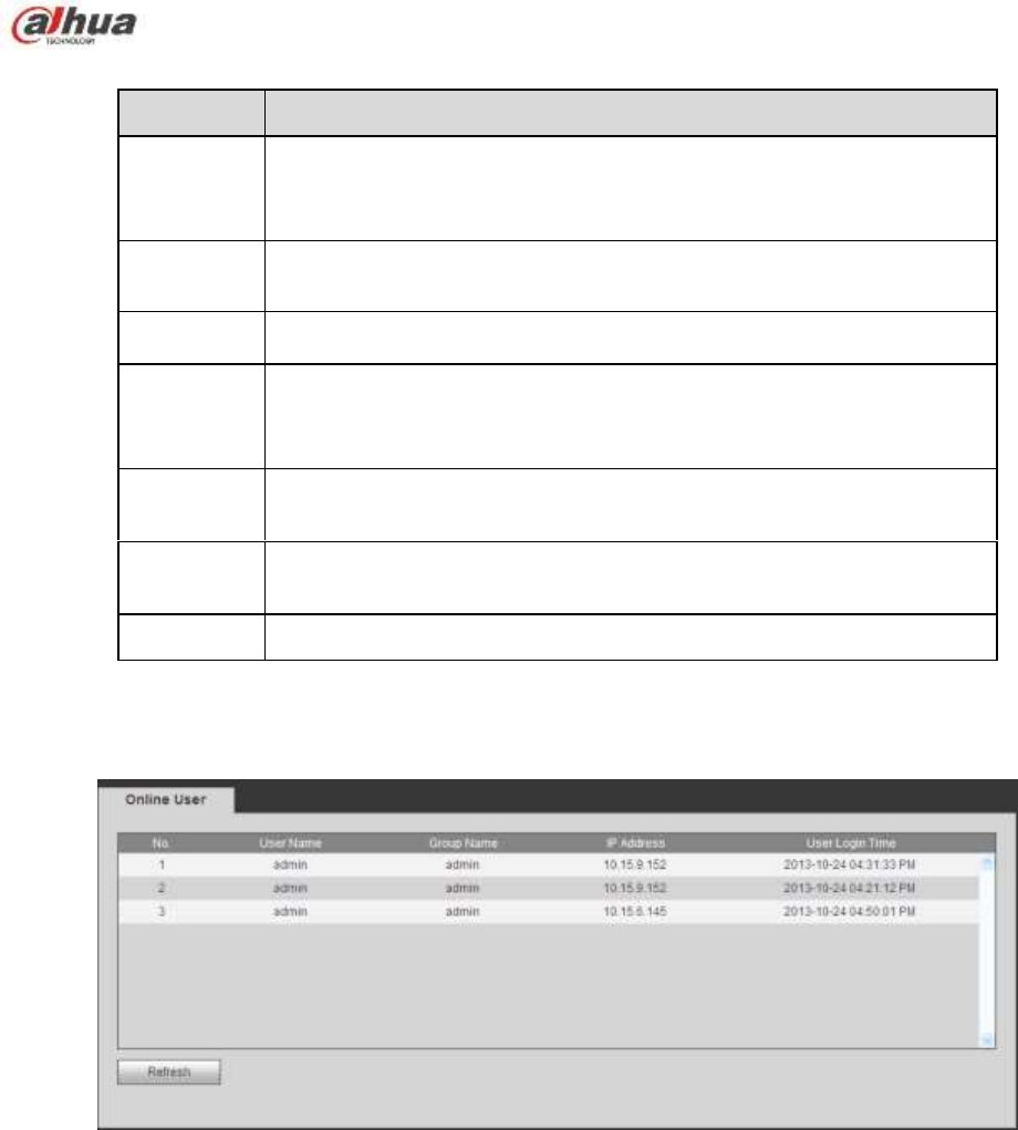
357
Please refer to the following sheet for log parameter information.
Parameter
Function
Type
Log types include: system operation, configuration operation, data
operation, event operation, record operation, user management, log
clear.
Start time
Set the start time of the requested log.
End time
Set the end time of the requested log.
Search
You can select log type from the drop down list and then click search
button to view the list.
You can click the stop button to terminate current search operation.
Detailed
information
You can select one item to view the detailed information.
Clear
You can click this button to delete all displayed log files. Please
note system does not support clear by type.
Backup
You can click this button to backup log files to current PC.
5.9.3 Online User
The online user interface is shown as in Figure 5-118.
Figure 5-118
5.10 Playback
Click Playback button, you can see an interface is shown as in Figure 5-119.
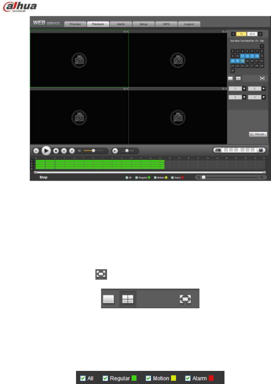
358
Figure 5-119
5.10.1 Search Record
Please set record type, record date, window display mode and channel name.
Select Date
You can click the date on the right pane to select the date. The green highlighted date is system current
date and the blue highlighted date means it has record files.
Window Split
Select window split mode. Click to display in full screen. Click ESC button to exit. See Figure 5-120.
Figure 5-120
Select Channel
1~4 means main stream and A1~A4 means sub stream.
Select Record Type
Check the corresponding box to select record type. See Figure 5-121.
Figure 5-121
5.10.2 File List
Click File list button, you can see the corresponding files in the list. See Figure 5-122.
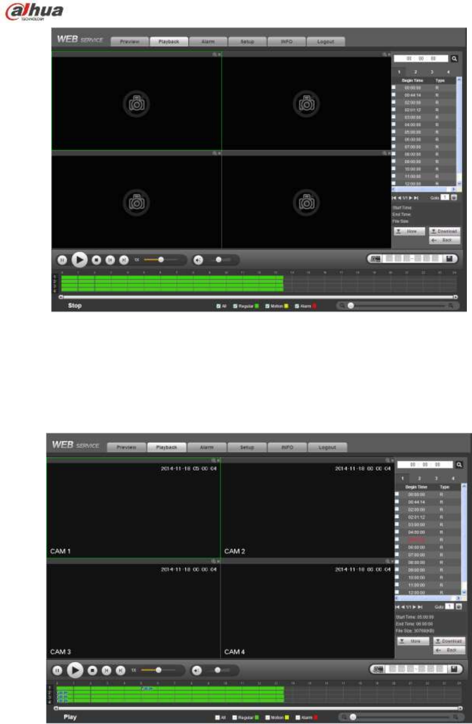
359
Figure 5-122
5.10.3 Playback
Select a file you want to play and then click Play button, system can begin playback. You can select to
playback in full-screen. Please note for one channel, system can not playback and download at the same
time. You can use the playback control bar to implement various operations such as play, pause, stop,
slow play, fast play and etc. See Figure 5-123.
Figure 5-123
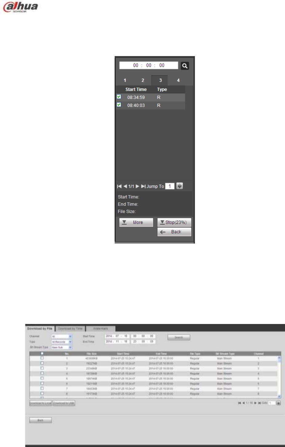
360
5.10.4 Download
Select the file(s) you want to download and then click download button, you can see an interface shown
as in Figure 5-124. The Download button becomes Stop button and there is a process bar for your
reference. Please go to you default file saved path to view the files.
Figure 5-124
5.10.5 Load more
It is for you to search record or picture. You can select record channel, record type and record time to
download. Or you can use watermark function to verify file.
5.10.5.1 Download By File
Select channel, record type, bit stream type and then input start time and end time. Click Search button,
the download by file interface is shown as in Figure 5-125.
Figure 5-125
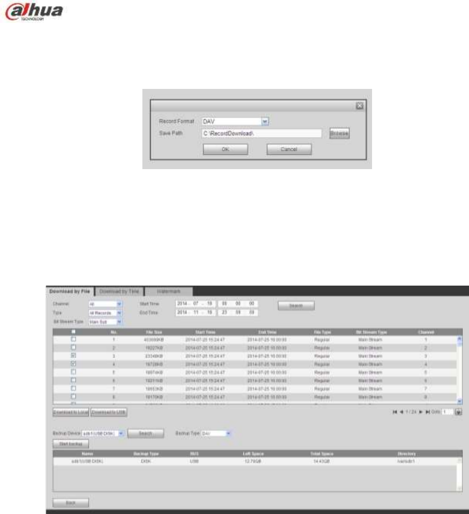
361
Check the file(s) you want to download and there are two options for you to save the file(s).
Download to local
Click Download to local, system pops up the following interface for you to set record format and saved
path. See Figure 5-126.
Figure 5-126
You can click OK to download and view the download process. After the download operation, you can see
corresponding dialog box.
Download to USB
Connect the corresponding p peripheral device, and then click Download to USB button, you can see the
following interface. See Figure 5-127.
Figure 5-127
Select Backup device and backup type first and then click Start backup button.
After the download operation, you can see corresponding dialogue box.
5.10.5.2 Download by Time
Select channel, bit stream type, start time and end time.
Click Download to Local button, you can see download by time interface is shown as in Figure 5-128.
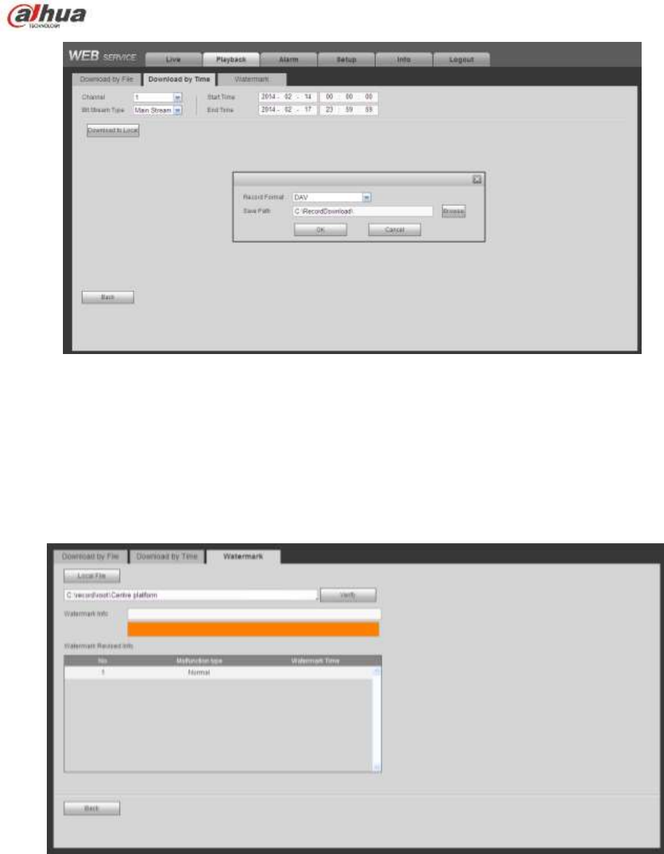
362
Figure 5-128
Set record format and saved path, you can click OK to download and view the download process. After
the download operation, you can see corresponding dialog box.
5.10.5.3 Watermark
Watermark interface is shown as In Figure 5-129. Please select a file and then click Verify button to see
the file has been tampered with or not
Figure 5-129
5.11 Alarm
Click alarm function, you can see an interface is shown as Figure 5-130.
Here you can set device alarm type and alarm sound setup (Please make sure you have enabled audio
function of corresponding alarm events.).
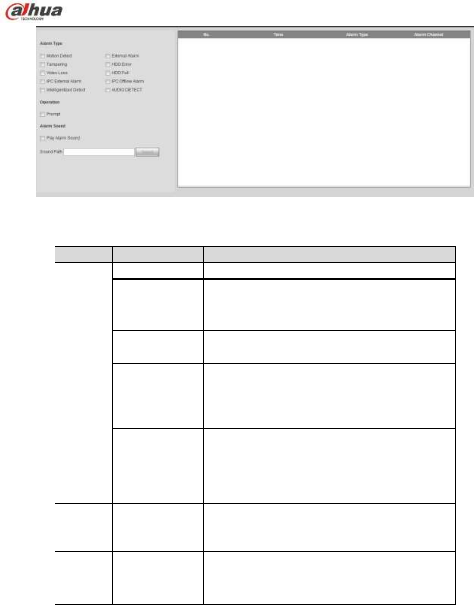
363
Figure 5-130
Please refer to the following sheet for detailed information.
Type
Parameter
Function
Alarm
Type
Video loss
System alarms when video loss occurs.
Motion detection
System alarms when motion detection alarm
occurs.
Tampering
System alarms when camera is viciously masking.
Disk full
System alarms when disk is full.
Disk error
System alarms when disk error occurs.
External alarm
Alarm input device sends out alarm.
IPC external
alarm
It refers to the on-off signal from the network
camera. It can activate the NVR local activation
operation.
IPC offline alarm
System can generate an alarm when the network
camera and the NVR are disconnected.
Intelligent detect
System alarms when IVS alarm occurs.
Audio detect
System alarms when audio detect is abnormal.
Operation
Prompt
Check the box here, system can automatically pops
up an alarm icon on the Alarm button in the main
interface when there is an alarm.
Alarm
Sound
Play alarm
sound
System sends out alarm sound when an alarm
occurs. You can specify as you wish.
Sound path
Here you can specify alarm sound file.
5.12 Log out
Click log out button, system goes back to log in interface. See Figure 5-131.
You need to input user name and password to login again.
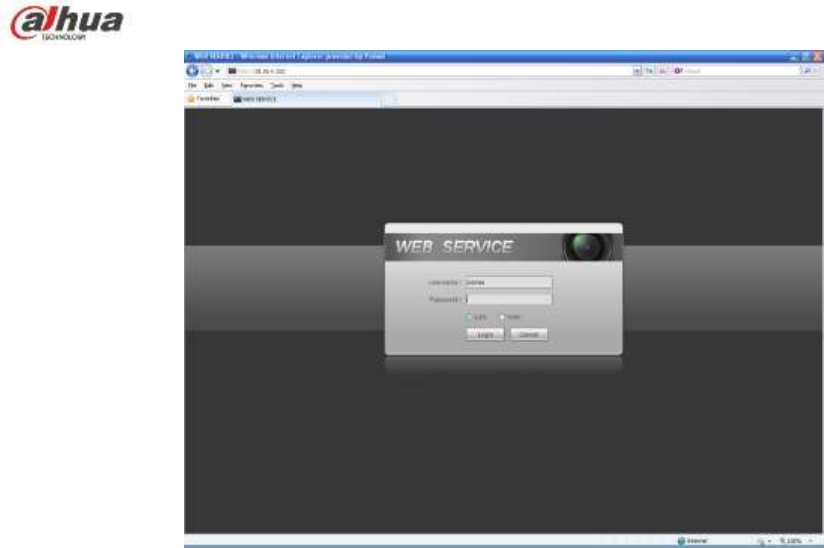
364
Figure 5-131
5.13 Un-install Web Control
You can use web un-install tool ―uninstall web.bat‖ to un-install web control.
Please note, before you un-installation, please close all web pages, otherwise the un-installation
might result in error

365
6 Glossary
DHCP: DHCP (Dynamic Host Configuration Protocol) is a network protocol. It is one of the TCP/IP
protocol cluster. It is principally used to assign temporary IP addresses to computers on a network.
DDNS: DDNS (Dynamic Domain Name Server) is a service that maps Internet domain names to IP
addresses. This service is useful to anyone who wants to operate a server (web server, mail server,
ftp server and etc) connected to the internet with a dynamic IP or to someone who wants to connect
to an office computer or server from a remote location with software.
eSATA: eSATA(External Serial AT) is an interface that provides fast data transfer for external storage
devices. It is the extension specifications of a SATA interface.
GPS: GPS (Global Positioning System) is a satellite system, protected by the US military, safely
orbiting thousands of kilometers above the earth.
PPPoE: PPPoE (Point to Point Protocol over Ethernet) is a specification for connecting multiple
computer users on an Ethernet local area network to a remote site. Now the popular mode is ADSL
and it adopts PPPoE protocol.
WIFI: Wi-Fi is the name of a popular wireless networking technology that uses radio waves to
provide wireless high-speed Internet and network connections. The standard is for wireless local
area networks (WLANs). It is like a common language that all the devices use to communicate to
each other. It is actually IEEE802.11, a family of standard The IEEE (Institute of Electrical and
Electronics Engineers Inc.)
3G: 3G is the wireless network standard. It is called 3G because it is the third generation of cellular
telecom standards. 3G is a faster network for phone and data transmission and speed Is over several
hundred kbps. Now there are four standards: CDMA2000, WCDMA, TD-SCDMA and WiMAX.
Dual-stream: The dual-stream technology adopts high-rate bit stream for local HD storage such as
QCIF/CIF/2CIF/DCIF/4CIF encode and one low-rate bit stream for network transmission such as
QCIF/CIF encode. It can balance the local storage and remote network transmission. The
dual-stream can meet the difference band width requirements of the local transmission and the
remote transmission. In this way, the local transmission using high-bit stream can achieve HD
storage and the network transmission adopting low bit stream suitable for the fluency requirements of
the 3G network such as WCDMA, EVDO, TD-SCDMA..
On-off value: It is the non-consecutive signal sampling and output. It includes remote sampling and
remote output. It has two statuses: 1/0.

366
7 FAQ
Questions
Solutions
NVR can not boot up
properly.
Input power is not correct.
Power connection is not correct.
Power switch button is damaged.
Program upgrade is wrong.
HDD malfunction or something wrong with HDD ribbon.
Seagate DB35.1, DB35.2,SV35 or Maxtor 17-g has compatibility
problem. Please upgrade to the latest version to solve this
problem.
Front panel error.
Main board is damaged.
NVR often automatically
shuts down or stops
running.
Input voltage is not stable or it is too low.
HDD malfunction or something wrong with the ribbon.
Button power is not enough.
Front video signal is not stable.
Working environment is too harsh, too much dust.
Hardware malfunction.
System can not detect
hard disk.
HDD is broken.
HDD ribbon is damaged.
HDD cable connection is loose.
Main board SATA port is broken.
There is no video output
whether it is one-channel,
multiple-channel or
all-channel output.
Program is not compatible. Please upgrade to the latest version.
Brightness is 0. Please restore factory default setup.
Check your screen saver.
NVR hardware malfunctions.
I can not search local
records.
HDD ribbon is damaged.
HDD is broken.
Upgraded program is not compatible.
The recorded file has been overwritten.
Record function has been disabled.
Video is distorted when
searching local records.
Video quality setup is too low.
Program read error, bit data is too small. There is mosaic in the full
screen. Please restart the NVR to solve this problem.
HDD data ribbon error.
HDD malfunction.
NVR hardware malfunctions.
Time display is not
correct.
Setup is not correct
Battery contact is not correct or voltage is too low.
Crystal is broken.

367
Questions
Solutions
NVR can not control PTZ.
Front panel PTZ error
PTZ decoder setup, connection or installation is not correct.
Cable connection is not correct.
PTZ setup is not correct.
PTZ decoder and NVR protocol is not compatible.
PTZ decoder and NVR address is not compatible.
When there are several decoders, please add 120 Ohm between
the PTZ decoder A/B cables furthest end to delete the
reverberation or impedance matching. Otherwise the PTZ control
is not stable.
The distance is too far.
I can not log in client-end
or web.
For Windows 98 or Windows ME user, please update your system
to Windows 2000 sp4. Or you can install client-end software of
lower version. Please note right now, our NVR is not compatible
with Windows VISTA control.
ActiveX control has been disabled.
No dx8.1 or higher. Please upgrade display card driver.
Network connection error.
Network setup error.
Password or user name is invalid.
Client-end is not compatible with NVR program.
There is only mosaic no
video when preview or
playback video file
remotely.
Network fluency is not good.
Client-end resources are limit.
Current user has no right to monitor.
Network connection is
not stable.
Network is not stable.
IP address conflict.
MAC address conflict.
PC or device network card is not good.
Burn error /USB back
error.
Burner and NVR are in the same data cable.
System uses too much CPU resources. Please stop record first
and then begin backup.
Data amount exceeds backup device capacity. It may result in
burner error.
Backup device is not compatible.
Backup device is damaged.
Keyboard can not control
NVR.
NVR serial port setup is not correct
Address is not correct
When there are several switchers, power supply is not enough.
Transmission distance is too far.

368
Questions
Solutions
Alarm signal can not been
disarmed.
Alarm setup is not correct.
Alarm output has been open manually.
Input device error or connection is not correct.
Some program versions may have this problem. Please upgrade
your system.
Alarm function is null.
Alarm setup is not correct.
Alarm cable connection is not correct.
Alarm input signal is not correct.
There are two loops connect to one alarm device.
Record storage period is
not enough.
Camera quality is too low. Lens is dirty. Camera is installed against
the light. Camera aperture setup is not correct.
HDD capacity is not enough.
HDD is damaged.
Can not playback the
downloaded file.
There is no media player.
No DXB8.1 or higher graphic acceleration software.
There is no DivX503Bundle.exe control when you play the file
transformed to AVI via media player.
No DivX503Bundle.exe or ffdshow-2004 1012 .exe in Windows XP
OS.
Forgot local menu
operation password or
network password
Please contact your local service engineer or our sales person for
help. We can guide you to solve this problem.
There is no video. The
screen is in black.
IPC IP address is not right.
IPC port number is not right.
IPC account (user name/password) is not right.
IPC is offline.
The displayed video is not
full in the monitor.
Please cheek current resolution setup. If the current setup is
1920*1080, then you need to set the monitor resolution as 1920*1080.
There is no HDMI output.
Displayer is not in HDMI mode.
HDMI cable connection is not right.
The video is not fluent
when I view in
multiple-channel mode
from the client-end.
The network bandwidth is not sufficient. The multiple-channel
monitor operation needs at least 100M or higher.
Your PC resources are not sufficient. For 16-ch remote monitor
operation, the PC shall have the following environment:
Quad Core, 2G or higher memory, independent displayer,
display card memory 256M or higher.

369
Questions
Solutions
I can not connect to the
IPC
Please make sure the IPC has booted up.
IPC network connection is right and it is online
IPC IP is in the blacklist.
The device has connected to the too many IPC. It can not transmit
the video.
Check the IPC port value and the time zone is the same as the
NVR.
Make sure current network environment is stable.
After I set the NVR
resolution as 1080P, my
monitor can not display.
Shut down the device and then reboot. When you reboot, please press
the Fn button at the same time and then release after 5 seconds. You
can restore NVR resolution to the default setup.
My admin account has
been changed and I can
not log in.
Use telnet and then input the following command:
cd /mnt/mtd/Config/
rm -rf group
rm -rf password
Reboot the device to restore the default password.
After I login the Web , I
can not find the remote
interface to add the IPC.
Please clear the Web controls and load again.
There is IP and gateway, I
can access the internet
via the router. But I can
not access the internet
after I reboot the NVR.
Please use command PING to check you can connect to the gateway
or not. Use telnet to access and then use command ―ifconfig –a‖ to
check device IP address. If you see the subnet mask and the gateway
has changed after the reboot. Please upgrade the applications and set
again.
I use the VGA montior.I
want to know if I use the
multple-window mode, I
see the video from the
main stream or the sub
stream?
For 32-channel series product, the 9/16-window is using the sub
stream.
For 4/8/16 series product, system is using the main stream no
matter you are in what display mode.
Daily Maintenance
Please use the brush to clean the board, socket connector and the chassis regularly.
The device shall be soundly earthed in case there is audio/video disturbance. Keep the device away
from the static voltage or induced voltage.
Please unplug the power cable before you remove the audio/video signal cable, RS232 or RS485
cable.
Do not connect the TV to the local video output port (VOUT).It may result in video output circuit.
Always shut down the device properly. Please use the shutdown function in the menu, or you can
press the power button in the rear pane for at least three seconds to shut down the device.

370
Otherwise it may result in HDD malfunction.
Please make sure the device is away from the direct sunlight or other heating sources. Please keep
the sound ventilation.
Please check and maintain the device regularly.

371
8 Appendix A HDD Capacity Calculation
Calculate total capacity needed by each device according to video recording (video recording type and
video file storage time).
Step 1: According to Formula (1) to calculate storage capacity
i
q
that is the capacity of each channel
needed for each hour, unit Mbyte.
102436008 ii dq
(1)
In the formula:
i
d
means the bit rate, unit Kbit/s
Step 2: After video time requirement is confirmed, according to Formula (2) to calculate the storage
capacity
i
m
, which is storage of each channel needed unit Mbyte.
i
m
=
i
q
×
i
h
×
i
D
(2)
In the formula:
i
h
means the recording time for each day (hour)
i
D
means number of days for which the video shall be kept
Step 3: According to Formula (3) to calculate total capacity (accumulation)
T
q
that is needed for all
channels in the device during scheduled video recording.
c
i
iT mq
1
(3)
In the formula:
c
means total number of channels in one device
Step 4: According to Formula (4) to calculate total capacity (accumulation)
T
q
that is needed for all
channels in device during alarm video recording (including motion detection).
c
i
iT mq
1
×a% (4)
In the formula:a% means alarm occurrence rate

372
9 Appendix B Compatible Network Camera List
Please note all the models in the following list for reference only. For those products not included in the
list, please contact your local retailer or technical supporting engineer for detailed information.
Manufact
ure
Model
Version
Video Encode
Audio/Vid
eo
Protocol
AXIS
P1346
5.40.9.2
H264
√
ONVIF/Private
P3344/P3344-
E
5.40.9.2
H264
√
ONVIF/Private
P5512
-
H264
√
ONVIF/Private
Q1604
5.40.3.2
H264
√
ONVIF/Private
Q1604-E
5.40.9
H264
√
ONVIF/Private
Q6034E
-
H264
√
ONVIF/Private
Q6035
5.40.9 H264
√
ONVIF/Private
Q1755
- H264
√
ONVIF/Private
M7001
- H264
√
Private
M3204
5.40.9.2 H264
√
Private
P3367
HEAD LFP4_0
130220
H264
√
ONVIF
P5532-P
HEAD LFP4_0
130220
H264
√
ONVIF
ACTi
ACM-3511
A1D-220-V3.12
.15-AC
MPEG4
√
Private
ACM-8221
A1D-220-V3.13
.16-AC
MPEG4
√
Private
Arecont
AV1115
65246
H264
√
Private
AV10005DN
65197
H264
√
Private
AV2115DN
65246
H264
√
Private
AV2515DN
65199
H264
√
Private
AV2815
65197
H264
√
Private
AV5115DN
65246
H264
√
Private
AV8185DN
65197
H264
√
Private
Bosch
NBN-921-P
-
H264
√
ONVIF
NBC-455-12P
-
H264
√
ONVIF
VG5-825
9500453
H264
√
ONVIF
NBN-832
66500500
H264
√
ONVIF
VEZ-211-IWT
EIVA
-
H264
√
ONVIF
NBC-255-P
15500152
H264
√
ONVIF
VIP-X1XF
-
H264
√
ONVIF
Brikcom
B0100
-
H264
√
ONVIF
D100
-
H264
√
ONVIF
GE-100-CB
-
H264
√
ONVIF
FB-100A
v1.0.3.9
H264
√
ONVIF
FD-100A
v1.0.3.3
H264
√
ONVIF

373
Manufact
ure
Model
Version
Video Encode
Audio/Vid
eo
Protocol
Cannon
VB-M400
-
H264
√
Private
CNB
MPix2.0DIR
XNETM112011
1229
H264
√
ONVIF
VIPBL1.3MIR
VF
XNETM210011
1229
H264
√
ONVIF
IGC-2050F
XNETM210011
1229
H264
√
ONVIF
CP PLUS
CP-NC9-K
6.E.2.7776
H264
√
ONVIF/Private
CP-NC9W-K
6.E.2.7776
H264
√
Private
CP-ND10-R
cp20111129AN
S
H264
√
ONVIF
CP-ND20-R
cp20111129AN
S
H264
√
ONVIF
CP-NS12W-C
R
cp20110808NS H264
√
ONVIF
VS201
cp20111129NS H264
√
ONVIF
CP-NB20-R
cp20110808BN
S
H264
√
ONVIF
CP-NT20VL3-
R
cp20110808BN
S
H264
√
ONVIF
CP-NS36W-A
R
cp20110808NS
H264
√
ONVIF
CP-ND20VL2-
R
cp20110808BN
S
H264
√
ONVIF
CP-RNP-1820
cp20120821NS
A
H264
√
Private
CP-RNC-TP2
0FL3C
cp20120821NS
A
H264
√
Private
CP-RNP-12D
cp20120828AN
S
H264
√
Private
CP-RNC-DV1
0
cp20120821NS
A
H264
√
Private
CP-RNC-DP2
0FL2C
cp20120821NS
A
H264
√
Private
Dynacolor
ICS-13
d20120214NS
H264
√
ONVIF/Private
ICS-20W
vt20111123NSA
H264
√
ONVIF/Private
NA222
-
H264
√
ONVIF
MPC-IPVD-03
13
k20111208ANS
H264
√
ONVIF/Private
MPC-IPVD-03
13AF
k20111208BNS
H264
√
ONVIF/Private
Honeywell
HIDC-1100PT
h.2.2.1824
H264
√
ONVIF
HIDC-1100P
h.2.2.1824
H264
√
ONVIF

374
Manufact
ure
Model
Version
Video Encode
Audio/Vid
eo
Protocol
HIDC-0100P
h.2.2.1824
H264
√
ONVIF
HIDC-1300V
2.0.0.21
H264
√
ONVIF
HICC-1300W
2.0.1.7
H264
√
ONVIF
HICC-2300
2.0.0.21
H264
√
ONVIF
HDZ20HDX
H20130114NS
A
H264
√
ONVIF
LG
LW342-FP
-
H264
√
Private
LNB5100
-
H264
√
ONVIF
Imatek
KNC-B5000
-
H264
√
Private
KNC-B5162
-
H264
√
Private
KNC-B2161
-
H264
√
Private
Panasonic
NP240/CH
- MPEG4
√
Private
WV-NP502
- MPEG4
√
Private
WV-SP102H
1.41 H264
√
ONVIF/Private
WV-SP105H
- H264
√
ONVIF/Private
WV-SP302H
1.41 H264、MPEG4
√
ONVIF/Private
WV-SP306H
1.4 H264、MPEG4
√
ONVIF/Private
WV-SP508H
- H264、MPEG4
√
ONVIF/Private
WV-SP509H
- H264、MPEG4
√
ONVIF/Private
WV-SF332H
1.41 H264、MPEG4
√
ONVIF/Private
WV-SW316H
1.41 H264、MPEG4
√
ONVIF/Private
WV-SW355H
1.41
H264、MPEG4
√
ONVIF/Private
WV-SW352H
-
H264、MPEG4
√
ONVIF/Private
WV-SW152E
1.03
H264、MPEG4
√
ONVIF/Private
WV-SW558H
-
H264、MPEG4
√
ONVIF/Private
WV-SW559H
-
H264、MPEG4
√
ONVIF/Private
WV-SP105H
1.03
H264、MPEG4
√
ONVIF/Private
WV-SW155E
1.03
H264、MPEG4
√
ONVIF/Private
WV-SF336H
1.44
H264、MPEG4
√
ONVIF/Private
WV-SF332H
1.41
H264、MPEG4
√
ONVIF/Private
WV-SF132E
1.03
H264、MPEG4
√
ONVIF/Private
WV-SF135E
1.03
H264、MPEG4
√
ONVIF/Private
WV-SF346H
1.41
H264、MPEG4
√
ONVIF/Private
WV-SF342H
1.41
H264、MPEG4
√
ONVIF/Private
WV-SC385H
1.08
H264、MPEG4
√
ONVIF/Private
WV-SC386H
1.08
H264、MPEG4
√
ONVIF/Private
WV-SP539
1.66
H264、MPEG4
√
ONVIF
DG-SC385
1.66
H264、MPEG4
√
ONVIF
PELCO
IXSOLW
1.8.1-20110912
-1.9082-A1.661
7
H264
√
Private
IDE20DN
1.7.41.9111-O3
.6725
H264
√
Private

375
Manufact
ure
Model
Version
Video Encode
Audio/Vid
eo
Protocol
D5118
1.7.8.9310-A1.
5288
H264
√
Private
IM10C10
1.6.13.9261-O2
.4657
H264
√
Private
DD4N-X
01.02.0015
MPEG4
√
Private
DD423-X
01.02.0006
MPEG4
√
Private
D5220
1.8.3-FC2-2012
0614-1.9320-A
1.8035
H264
√
Private
Samsung
SNB-3000P
2.41
H264、MPEG4
√
ONVIF/Private
SNP-3120
1.22_110120_1
H264、MPEG4
√
ONVIF/Private
SNP-3370
1.21_110318 MPEG4
√
Private
SNB-5000
2.10_111227 H264、MPEG4
√
ONVIF/Private
SND-5080
- H264、MPEG4
√
Private
SNZ-5200
1.02_110512 H264、MPEG4
√
ONVIF/Private
SNP-5200
1.04_110825 H264、MPEG4
√
ONVIF/Private
SNB-7000
1.10_110819 H264
√
ONVIF/Private
SNB-6004
V1.0.0 H264
√
ONVIF
Sony
SNC-DH110
1.50.00 H264
√
ONVIF/Private
SNC-CH120
1.50.00 H264
√
ONVIF/Private
SNC-CH135
1.73.01 H264
√
ONVIF/Private
SNC-CH140
1.50.00
H264
√
ONVIF/Private
SNC-CH210
1.73.00
H264
√
ONVIF/Private
SNC-DH210
1.73.00
H264
√
ONVIF/Private
SNC-DH240
1.50.00
H264
√
ONVIF/Private
SNC-DH240-T
1.73.01
H264
√
ONVIF/Private
SNC-CH260
1.74.01
H264
√
ONVIF/Private
SNC-CH280
1.73.01
H264
√
ONVIF/Private
SNC-RH-124
1.73.00
H264
√
ONVIF/Private
SNC-RS46P
1.73.00
H264
√
ONVIF/Private
SNC-ER550
1.74.01
H264
√
ONVIF/Private
SNC-ER580
1.74.01
H264
√
ONVIF/Private
SNC-ER580
1.78.00
H264
√
ONVIF
SNC-VM631
1.4.0
H264
√
ONVIF
WV-SP306
1.61.00
H264、MPEG4
√
SDK
WV-SP306
1.61.00
H264
√
ONVIF
SNC-VB600
1.5.0
H264
√
Private
SNC-VM600
1.5.0
H264
√
Private
SNC-VB630
1.5.0
H264
√
Private
SNC-VM630
1.5.0
H264
√
Private
SANYO
VCC-HDN400
0PC
-
H264
√
ONVIF

376
Note
This manual is for reference only. Slight difference may be found in the user interface.
All the designs and software here are subject to change without prior written notice.
All trademarks and registered trademarks are the properties of their respective owners.
If there is any uncertainty or controversy, please refer to the final explanation of us.
Please visit our website or contact your local service engineer for more information.
ZHEJIANG DAHUA VISION TECHNOLOGY CO.,LTD.
Address:No.1199, Bin'an Road, Binjiang District, Hangzhou, P.R. China
Postcode: 310053
Tel: +86-571-87688883
Fax: +86-571-87688815
Email:overseas@dahuatech.com
Website: www.dahuatech.com