Zhejiang Flashforge 3D Technology FINDER 3D Printer User Manual
Zhejiang Flashforge 3D Technology CO., Ltd. 3D Printer Users Manual
Contents
- 1. Users Manual
- 2. user manual
Users Manual
Fin
d
F
d
er User Gui
d
F
lash
f
Flashforg
e
d
e | www.flas
h
f
org
e
U
e
Corporat
h
forge.com
e
Fin
d
U
ser
G
ion
d
er 3
D
G
uid
e
D
Pr
i
e
0086
-
i
nter
-
0579-82273
9
9
89

Finder User Guide | www.flashforge.com 0086-0579-82273989
2
Content
Content ........................................................................................................................... 2
Preface ........................................................................................................................... 3
Introduction .................................................................................................................... 4
Notice ............................................................................................................................. 5
Chapter 1: 3D Printing Technology ............................................................................... 8
Chapter 2: About Finder .............................................................................................. 10
2.1 About Your Finder .......................................................................................... 10
Chapter 3˖Unpacking ................................................................................................ 20
Chapter 4: Hardware Assembly ................................................................................... 25
4.1 Filament Installation ....................................................................................... 25
4.2 Printer Start-up ............................................................................................... 26
4.3 Loading Filament ............................................................................................ 26
Chapter 5: Build Plate Leveling ................................................................................... 30
Chapter 6: About Software .......................................................................................... 33
6.1 Software Installation ....................................................................................... 33
6.2 Exploring FlashPrint ....................................................................................... 33
Chapter 7: Basic Printing ............................................................................................. 57
7.1 Generate a Gcode ........................................................................................... 58
7.2 Print Methods ................................................................................................. 61
Chapter 8: Advanced Printing ...................................................................................... 64
8.1 Skills on Supports ........................................................................................... 72
8.2 Control over Printing Quality ......................................................................... 78
Chapter 9: Supports and Service .................................................................................. 83

Finder User Guide | www.flashforge.com 0086-0579-82273989
3
Preface
Note: Each device must be tested before leaving factory. If there are some residues in extruder
or some tiny scratcheson the build tape, it isnormal and won’taffect the printing quality.
On the completion of this User Guide, thanks all Flashforge engineers and the
Flashforge 3D printer users for their unremitting efforts and sincere assistance.
The Flashforge Finder User Guide is designed for the Finder users to start their
printing journey with Flashforge Finder. Even if you are familiar with earlier
Flashforge machines or 3D printing technology, we still recommend that please read
this guide, as there is lots of important information about the Finder for you to get a
better 3D experience.
For a better and more successful printing experience, you can refer to the following
materials:
(1) Quick Start Guide
Users will find the Quick Start Guide together with the printer accessories. The Quick
Start Guide will help you start your print journey as soon as possible.
(2) Official Flashforge Website: http://www.flashforge.com
The official Flashforge website contains the up-to-date information concerning
Flashforge software, firmware, device maintenance and so on. Users are also able to
get the contact information from there.

Finder User Guide | www.flashforge.com 0086-0579-82273989
4
Introduction
Notes
The Flashforge Finder 3D Printer User Guide contains the information needed for
you to set up and use this device.
This User Guide including the following parts: Preface, Introduction and after-sale
service.
The Preface section includes resource acquisition channel, the overall framework of
the manual, and the problems that should be paid attention to while printing.
The introduction section contains the overview of 3D printing technology, equipment
introduction, unpacking and installation of equipment, software installation and use.
After-sale section contains the user how to get the support and help.
xPlease read Flashforge Finder 3D Printer User Guide carefully before use.
·The User Guide is written based on Windows 7 OS.
·The version of the Flashprint is latest.

Finder User Guide | www.flashforge.com 0086-0579-82273989
5
Notice
Safety Notice
! Notices: Read all the instructions in the manual and familiarize yourself with the
Flashforge Finder User Guide before setting-up and using. Failure to comply with the
warning and instructions may result in individual injury, fire, equipment damage or
property damage.
PLEASE STRICTLY FOLLOW ALL THE SAFETY WARNINGS AND NOTICE
BELOW ALL THE TIME.
· Work Environment Safety
Keep your work place tidy.ķ
Do not operate Finder in the presence of flammable liquids, gases or dust.ĸ
Keep Finder out of children and untrained people’ reach.Ĺ
· Electrical Safety
Always use thķe Finder with a properly grounded outlet. Do not refit Finder plug.
Do not use Finder in damp or wet locations. Do not expose Finder to burning sun.ĸ
Do not abuse the cord. Ĺ
Avoid using the device during an thunderstorm.ĺ
In case of uncertain accidenĻt, please unplug the device if you do not use it for long.
·Personal Safety
Do not touch the nozzle and build plate during printing.ķ
Do not touch the nozzle after finishing printing.ĸ
Dress properly. Do not wear loose clothing or jewelry. Keep your hĹair, clothing and

Finder User Guide | www.flashforge.com 0086-0579-82273989
6
gloves away from moving parts.
Do not operate the device while you are tired or under the influence of drugs, ĺ
alcohol or medication.
·Cautions
Do not leave the device unattended for long.ķ
Do not make any modifications to the ĸdevice.
To lower the build plate before loading/unloading filament. (The distance between Ĺ
the nozzle and build plate should be kept for at least 50mm)
Operate the device in a wellĺ-ventilated environment.
Never use the device for illegal activities.Ļ
ļ Never use the device to make any food storage vessels.
Never use the device to make any electrical appliance.Ľ
Never put the model into your mouth.ľ
Do not remove the models with force.Ŀ
· Environment Requirements
Temperature: RT 15-30ć
Moisture: 20%-70%
· Filament Requirements
Do not abuse the filament. Please make sure you use the Flashforge filament or the
filament from the brands accepted by Flashforge.
· Filament Storage
All polymers degrade with time. Do not unpack until filament is needed. Filament
should be stored atclean and dry conditions.

Finder User Guide | www.flashforge.com 0086-0579-82273989
7
Legal Notice
All the information in this document is subject to any amendment or change without
the official authorization from Flashforge.
FLASHFORGE CORPORATION MAKES NO WARRANTY OF ANY KIND WITH
REGARD TO THIS DOCUMENT, INCLUDING, BUT NOT LIMITED TO, THE
IMPLIED WARRATIES OF MERCHANTA- BILITY AND FITNESS FOR A
PARTICULAR PURPOSE.
Flashforge shall not be liable for errors contained herein for incidental consequential
damages in connection with furnishing, performance or use of this material
This document contains proprietary information protected by copyright.
Copyright © 2016 Flashforge Corp. All Rights Reserved

Finder User Guide | www.flashforge.com 0086-0579-82273989
8
Chapter 1: 3D Printing Technology
3D printing refers to transforming three-dimensional models intophysical objects that
you can hold and touch. It is also called additivemanufacturing because the 3D model is
created by “adding” layers uponlayers of material until the object is fully formed.
Fused Filament Fabrication(FFF) is the most common method of 3D printing.It is also
the method that the Finder uses. It works by melting plasticmaterial called filament onto
a print surface in high temperature. Thefilament solidifies after it cools down, which
happens instantaneouslyafter it is extruded from the nozzle. 3D objects are formed with
thefilament laying down multiple layers.
1.1 Process
3D printing involves three steps:
1.) Make or download a 3D model
2.) Slice andexport the 3D model
3.) Build the 3D model
1.1.1 Make a 3D Model:
Currently, there are three ways to creating a3D model.
·Designing From Scratch You can use free CAD (computer-aideddesign) software
such as 3DTADA, AutoCAD, SolidWorks, Pro-E, and our own software Happy 3D to
design your own 3D model.
·3D Scanners An alternative method to creating a 3D model is to scanan
object. 3D scanners work by digitizing a physical object, collectingits geometric data,
and saving it to a file on your PC. There are alsoapps that can turn a mobile device into a

Finder User Guide | www.flashforge.com 0086-0579-82273989
9
3D scanner.
·From the Cloud The most popular way of obtaining a 3D model is to download it
from websites that allow users to upload 3D models that they designed.
E.g. :www. thingiverse.com
1.1.2 Slice and Export the 3D Model:
Slice software is the software that prepares 3D models for printing and turns them into
instructions for the 3D printers. FlashPrint is theslicing software used for the
FlashForge Finder.
Using FlashPrint, you can turn stl. files into g. or gx. files for printing. Then the files
can be transferred to yourFindervia USB cable, USB stick or Wi-Fi.
1.1.3 Build the 3D Model:
Once the output file has been transferred to yourFinder, it will startto turn the 3D model
into a physical object by laying down layers of filament.
Find
e
2.1
A
2.1
.
e
r User Guide
A
bout Yo
u
.
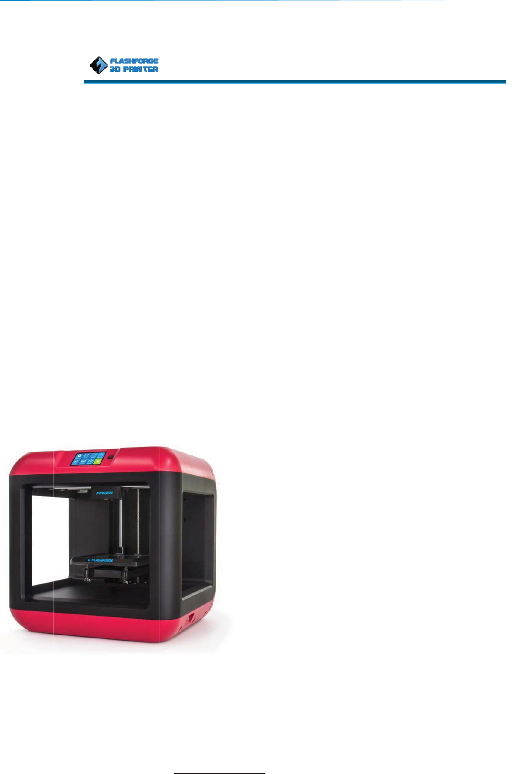
1 Views
F
1. Touch
s
2. Power
S
3. Nozzle
4. Z-axis
g
5. Build
p
| www.flashf
o
Cha
p
u
r Finde
r
F
ront
Right
s
creen
S
witch
g
uide rod
p
late
o
rge.com
p
ter
2
r
6.
L
7.
F
8.
E
9.
F
10.
10
2
: Ab
o
L
eveling k
n
F
ilament c
a
E
xtruder
F
ilament int
a
X-axis gui
d
o
ut Fi
n
ob
a
rtridge
a
ke
d
e rod
0086-05
7
nder
Top
Back
11. Sp
r
12. U
S
13. U
S
14. Po
w
7
9-82273989
r
ing presse
r
S
B cable
S
B stick inp
w
er input
r
input
ut

Finder User Guide | www.flashforge.com 0086-0579-82273989
11
2.1.2 Terms
Build Plate The surface on which the Finder builds an object.
Build Tape The blue tape that covers Finder’s build plate so that
the object can stick to the build plate well.
Build Volume The three dimensional amount of space that an object
will use once it is completed. The largest build volume
of Finder is 140*140*140mm.
Leveling Knobs Knobs under the build platform that are used for
adjusting the distance between the nozzle and build
plate.
Extruder The device that draws the filament from the spool,
melts it and pushes it through a nozzle into the build
plate.
Nozzle Also called “print head”, which located at the bottom
of the extruder where heated filament is squeezed out.
Extruder Fan To cool the outer assembly of the extruder and gear
motor
Filament Intake An opening located at the top of the extruder .
Filament Guide Tube A black plastic piece that guides the filament from the
filament box to the filament intake
Filament Cartridge A specific box for placing Flashforge filament
PVP Glue Stick A solid adhesive used for making the model stick to the
build plate firmly
Unclog Tool A tool that used for cleaning the extruder
Stamping Wrench A tool that used for seizing the nozzle’s metal cube

Finder User Guide | www.flashforge.com 0086-0579-82273989
12
2.1.3 Reference
Name Finder
Number of Extruder Single
Print Technology Fused Filament Fabrication(FFF)
Screen Size 3.5’’ color IPS Touch Screen
Build Volume 140×140×140mm
Layer Resolution 0.05 - 0.25mm
Build Accuracy ±0.1mm
Positioning Accuracy Z axis 0.0025mm; XY axis 0.011mm
Filament Diameter 1.75mmͧ±0.07ͨ
Nozzle Diameter 0.4mm
Build Speed 30-150 mm/s
Software FlashPrint
Support Formats Input:3MF/ STL/OBJ/FPP/BMP/PNG/JPG/JPEG
Output:GX/G
OS Win xp/Vista/7/8/10ǃMac OSǃLinux
Product Dimensions 420*420*420mm
Net Weight 11Kg
Adapter Power Input: AC 100V-240V, 50/60Hz ,1.7A
Output: DC 24V , 2.71A , 65W
Connectivity USB cable, USB stick, WIFI
Finder User Guide | www.flashforge.com 0086-0579-82273989
13
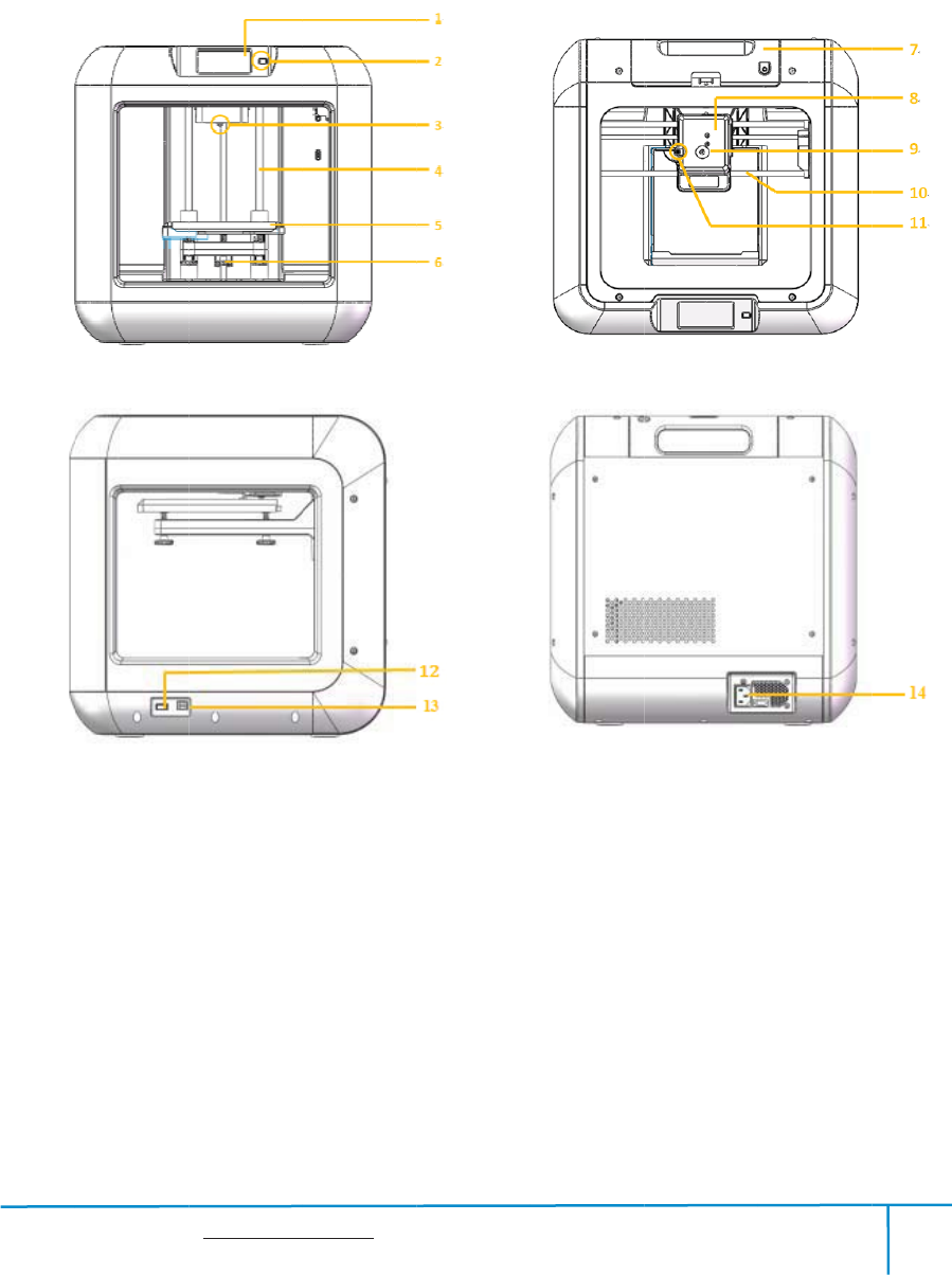
2.1.4 Interface Menus
Press Build
Read the print file from
yThe local memory card
yThe USB stick
yReturn arrow
Select the target print file among the list
yBuild: To begin printing
yCopy: To copy the files to the local
memory card from the USB stick.(The
button is not available while printing from
local memory card )
yDelete: To delete the print file
Print interface
yAbort: To abort the print job.
yPause/Resume: To suspend or resume the
print job.
yMore: To change filament and set up auto
shutdown during printing.
Finder User Guide | www.flashforge.com 0086-0579-82273989
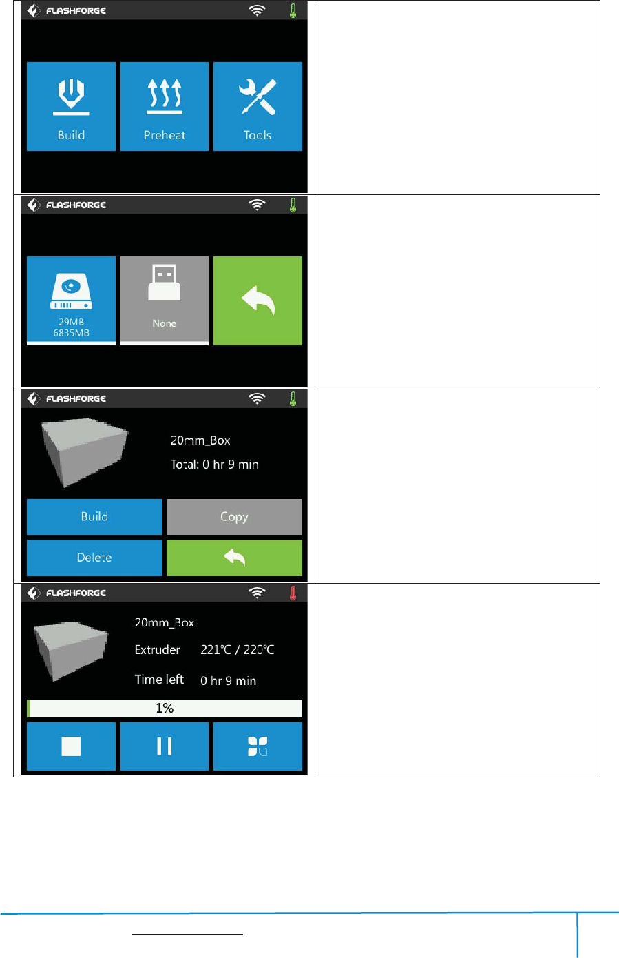
14
Tools in print interface
yFilament: To change filament during
printing.
(Note: You need to suspend the operation
first)
yFinish-Shutdown: To start auto shutdown
yCancel: To end the tool orders and return to
the print interface.
Preheat
Tap the [Preheat] button to enter the preheat
interface. Tap the [Start] button to heat up to
the setting temperature.
The default temperature is 220 .ć
Tap the temperature display bar to set the
temperature.
To set the preheat temperature.
Tap [Yes] to save the setting while tap [No]
to cancel the setting.
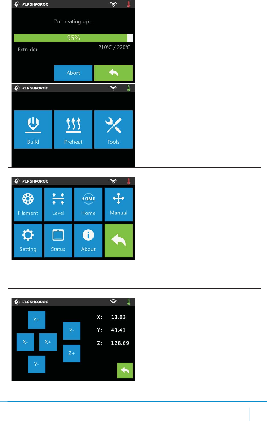
Finder User Guide | www.flashforge.com 0086-0579-82273989
15
The picture displays the preheat interface. It
shows the actual temperature and the target
temperature. Tap the [Abort] button to abort
the preheat job.
Tools
Tap [Tools] to enter tool options.
yFilament: To load/unload the filament.
yLevel: To adjust the build plate.
yHome: To make the X, Y and Z axes back
to the zero point.
yManual: To manually adjust the positions
of X, Y and Z axes.
ySetting: To implement relevant function
setups.
yStatus: The check the real-time status of
the printer.
yAbout: Information about the printer.
yReturn arrow
Manual adjustment
yY+: The extruder moves to the zero point,
that is, the back of the machine
yY-: The extruder moves to the direction
opposite to the Y+.
yX+: The extruder moves to the zero points,
that is, to the right direction
yX-: The extruder moves to the direction
opposite to the X+.
yZ+: The build plate elevates.
yZ-: The build plate descends.
Finder User Guide | www.flashforge.com 0086-0579-82273989
16
yReturn arrow
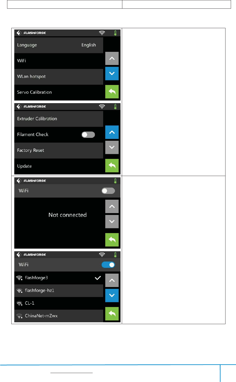
Tap [Setting] to enter the setting interface
yLanguage: To set the display language
yWIFI: To turn on/off the WIFI
y Wlan hotspot: To turn on/off the Wlan
hotspot.
yServo Calibration: To turn on/off the
servo or adjust the servo.
yExtruderCalibration: To adjust the initial
distance between the extruder and the
build plate.
yFilament Check Off: To turn on/off the
filament check
y Factory Resetreturn to factory setting
yUpdate: To update the firmware version.
yReturn arrow
WIFI:
yTurn on WIFI: Turn on the WIFI, release
the WIFI hotspot and set the WIFI on
computer
yReturn arrow
Finder User Guide | www.flashforge.com 0086-0579-82273989
17
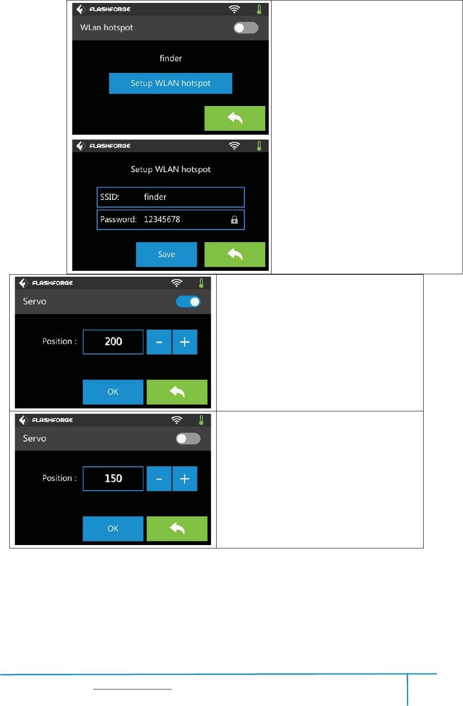
Servo On:
Actually, the present servo status is off.
And the servo’s swing arm withdraws.
Tap ‘+’ or ‘-’ to adjust the status of swing
arm. Tap ‘+’, the arm swings down while
tap ‘-’ , the arm swings up.
Servo OFF:
Actually, the present servo status is on. And the
servo’s swing arm withdraws. Tap ‘+’ or ‘-’ to
adjust the status of swing arm. Tap ‘+’, the arm
swings down while tap ‘-’ , the arm swings up.
WLan hotspot
yOFF/On: To turn on/off the Wlan hotspot.
ySetup Wlan hotspot:To set the SSID and
password.
ySSID:The name of hotspot.
yPassword: The password of hotspot.
ySave: To save the setting.
yReturn arrow
Finder User Guide | www.flashforge.com 0086-0579-82273989
18
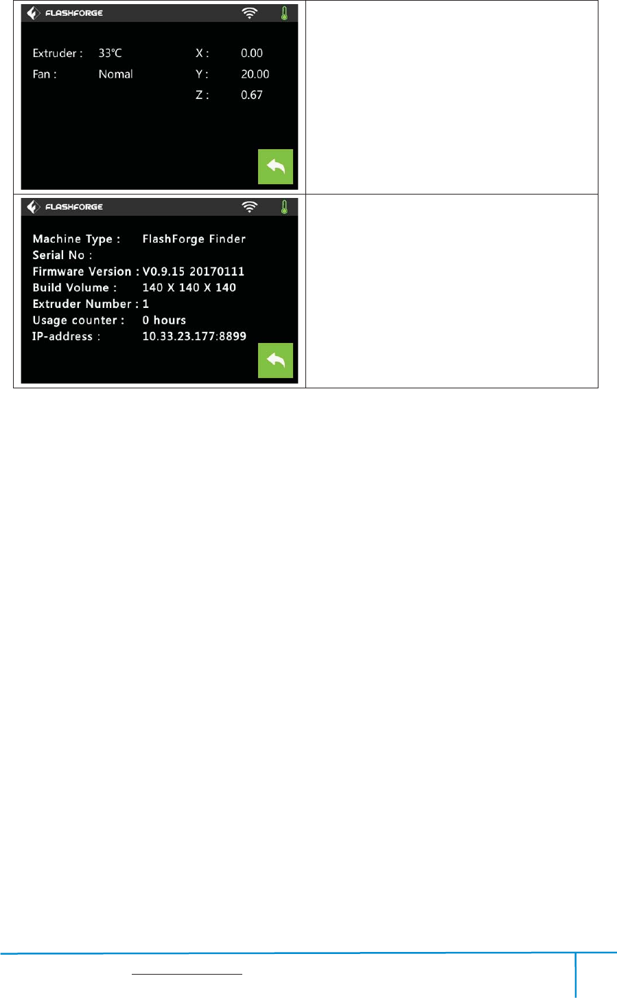
Status:
It displays the real-time status of the extruder
temperature, fan and filament.
About:
It displays the basic information about the
device.
Find
e
2.2
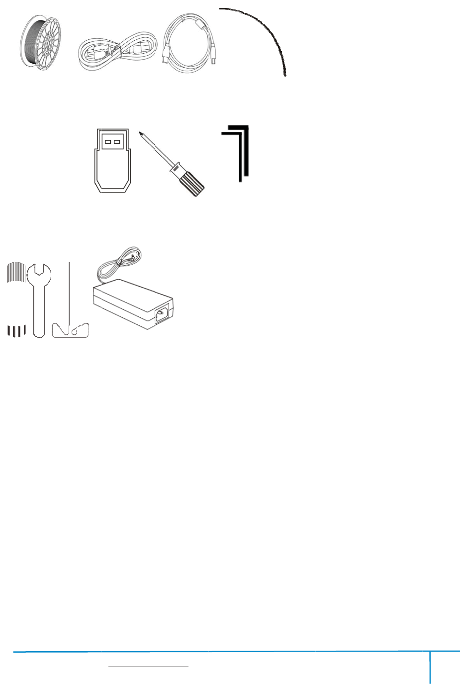
Fila
G
l
e
r User Guide
Accesso
r
ment*1
l
ueStick
| www.flashf
o
r
ies
Power
C
USB
St
a
o
rge.com
C
able
stick Alle
a
mpingWre
n
19
USBC
a
nWrenchͧ
n
ch
a
bleF
i
ͧ
M2.0/2.5
UnclogToo
0086-05
7
i
lamentGu
i
ͨ Screwdr
l
P
7
9-82273989
i
deTube
iver
P
owerAdap
t
t
er
Finder User Guide | www.flashforge.com 0086-0579-82273989
20
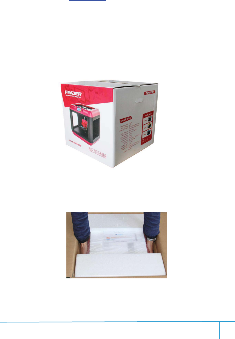
Chapter 3
˖
Unpacking
(reference video
˖
Unpacking
˅
This chapter will present you the whole unpacking procedure of Finder 3D
printer.(Note: Make sure you read the whole unpacking guide)
3-1
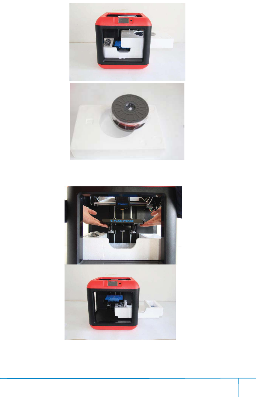
(3-1)Place the packaging box on a clean work surface.
ͧ3-2ͨOpen the box, grasp the two handles and then lift your Finder out of the box.
32
Finder User Guide | www.flashforge.com 0086-0579-82273989
21
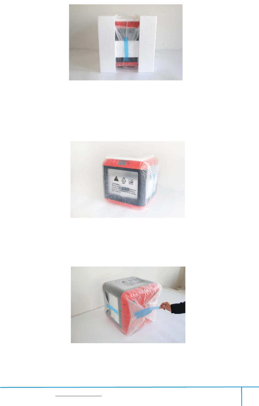
(3-3)Your Finder is wrapped by packaging materials, remove these materials step by
step.
(3-4)Remove the side protective foam sheets.
(3-5) Remove the bag to unveil the Finder
33
35
34
Finder User Guide | www.flashforge.com 0086-0579-82273989
22
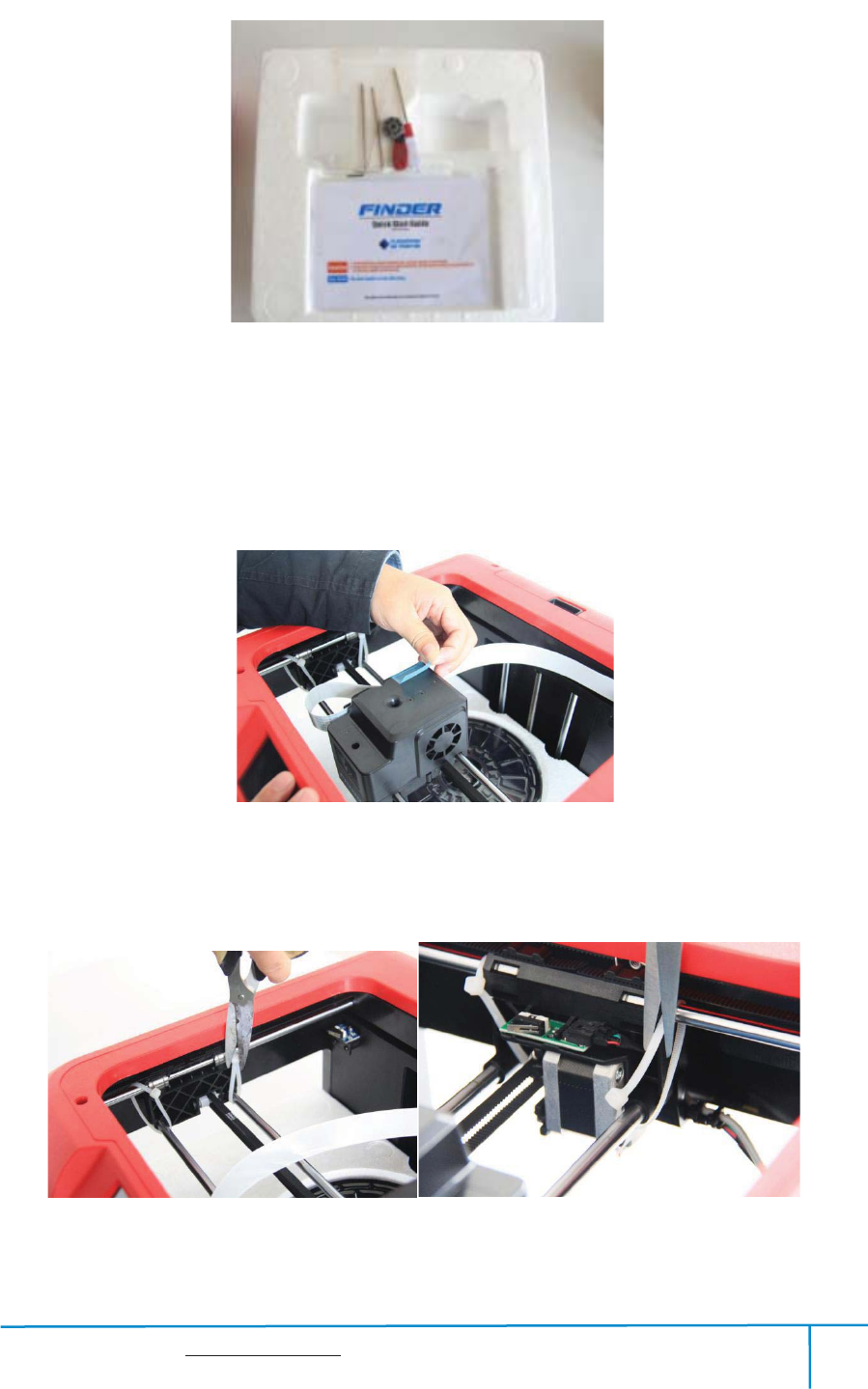
˄3-6˅On the top foam sheet, you can see one Quick Start Guide and a tool bag( USB
stick*1, leveling knob*1, Allen wrenches*3, stamping wrench*1, unclog tool*1, and
screwdriver*1).
˄3-7˅Remove the tape on for fixing the flat cable
.
(3-8) Cut off four ribbons that used for fixing the guide rod. Then slide the extruder to
36
37
38
Finder User Guide | www.flashforge.com 0086-0579-82273989
23
make sure the extruder is in good condition.
(3-9) Take the filament(Assign random color)out of the Finder.
3-10
(3-10) Lift the build plate up and take out the glue stick, power cable and USB cable.
39

Finder User Guide | www.flashforge.com 0086-0579-82273989
24
Congratulations! You have unpacked your Finder. Next, let’s move on to
hardware assembly of Finder.
Finder User Guide | www.flashforge.com 0086-0579-82273989
25
Chapter 4: Hardware Assembly
Your Finder has been installed before leaving factory, you can start up the Finder for
printing after mounting the filament spool and completing leveling.
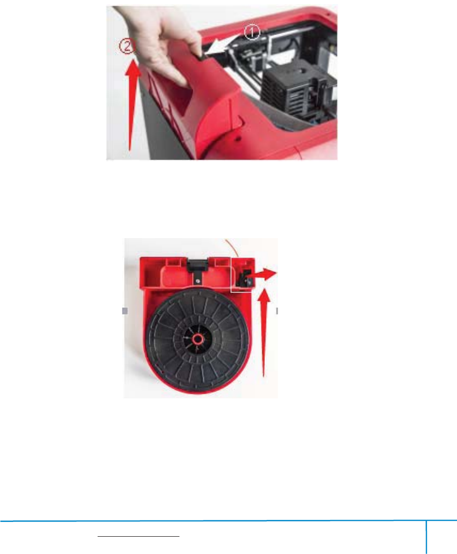
4.1 Filament Installation
4-1
(4-1) The filament cartridge is at the rear of Finder. Lift the cartridge out of the Finder.
4-2
(4-2) Take out the filament and thread it through the filament detecting equipment.
(Note: The filament should feeds from the bottom of the spool towards the top )
BlackFilamentDetecting
Equipment
Finder User Guide | www.flashforge.com 0086-0579-82273989
26
After installing the filament, put the cartridge back to the printer.
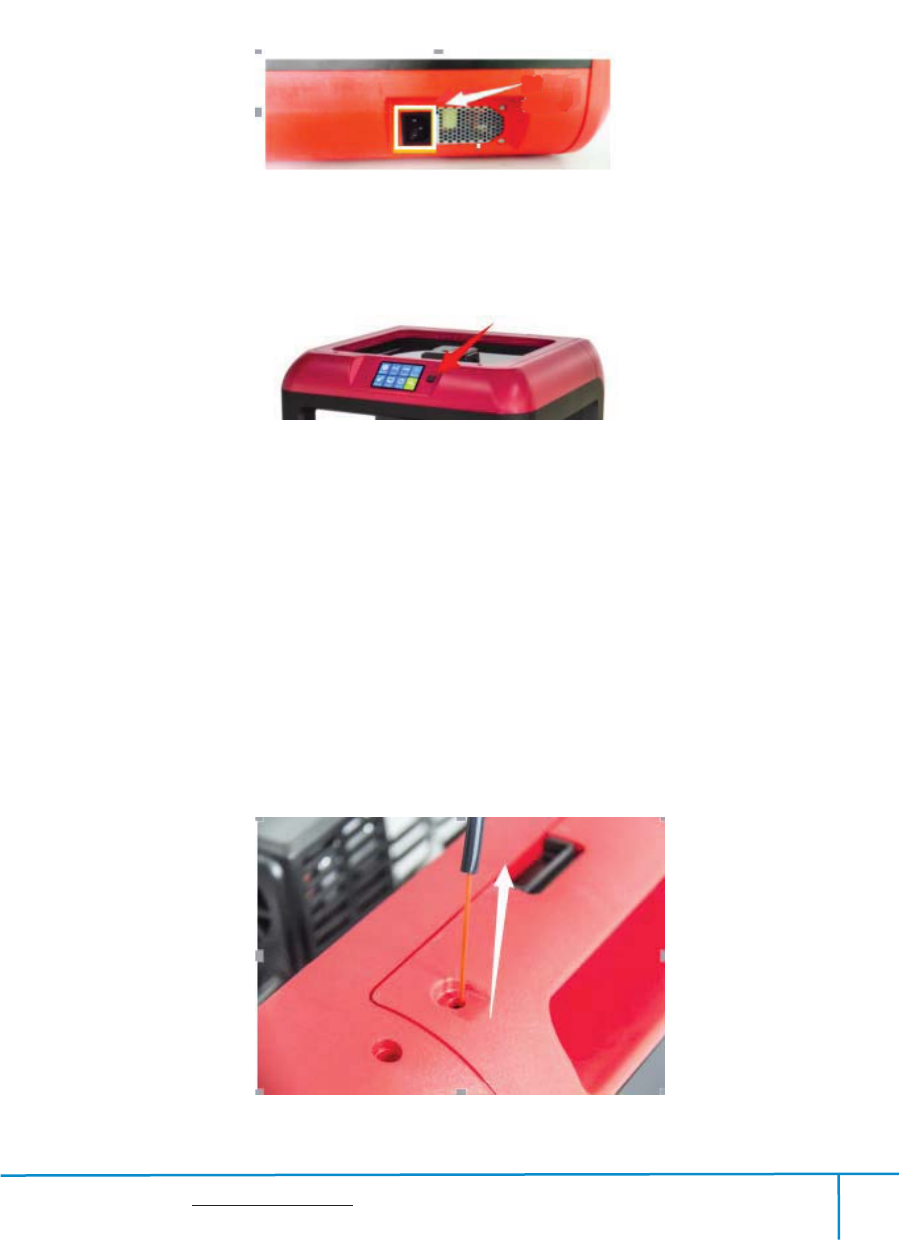
4.2 Printer Start-up
(4-3)Insert the power supply into the power input on the back of the Finder and plug
the power cord into an electrical outlet.
(4-4) Press the starter button to start the device.
4.3 Loading Filament
For stable filament loading and proper device protection, you need to install the
filament guide tube properly.
(4-5) Take out the filament guide tube, thread the filament from the filament
cartridge through the tube.
4-5
43
44
Finder User Guide | www.flashforge.com 0086-0579-82273989
27
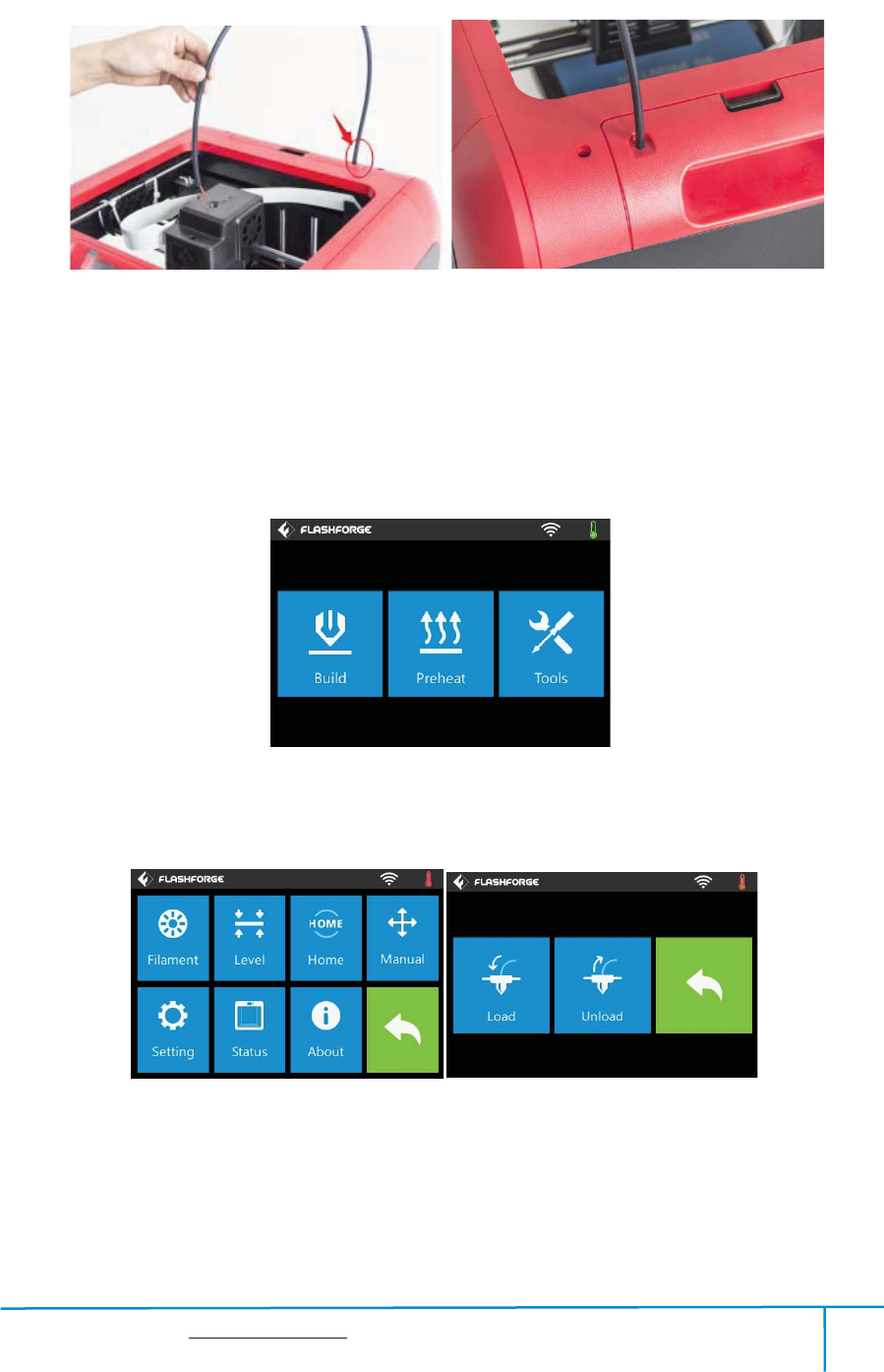
(4-6) Insert the filament from the filament guide tube into the filament intake.
Next, we will load the Flashforge filament.(Note: Please lower the build plate to
increase the distance between the nozzle and build plate to 50mm at least for
avoiding nozzle jam.)
(4-7) Tap[Tool].
4-6
4-8
(4-8) Tap [Filament]--[Load]
47
46
Finder User Guide | www.flashforge.com 0086-0579-82273989
28
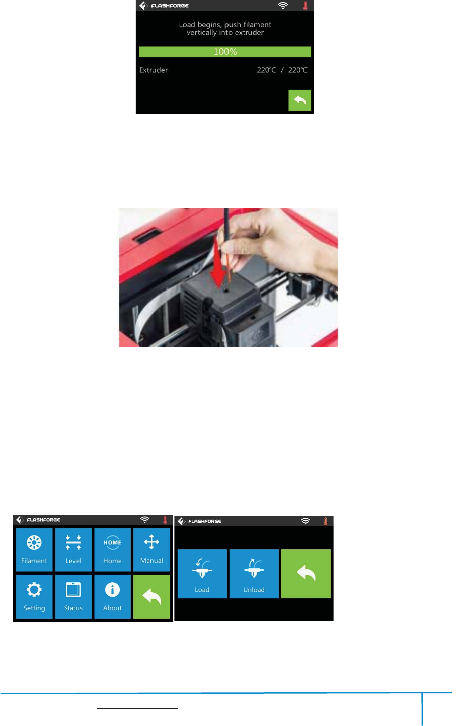
4-9
˄4-9˅After the extruder’s temperature reaches 220 , the printer will sound a beep to ć
prompt you to load the filament into the extruder.
4-10
˄4-10˅Insert the filament into the extruder at an upright angle. Then the filament will
be drawn through the extruder. Do not tap [Cancel] until the filament load the extruder
steadily.
4.4 Unloading Filament
4-11
(4-11) Tap [Tool]-[Unload] and the extruder starts heating up.
Finder User Guide | www.flashforge.com 0086-0579-82273989
29
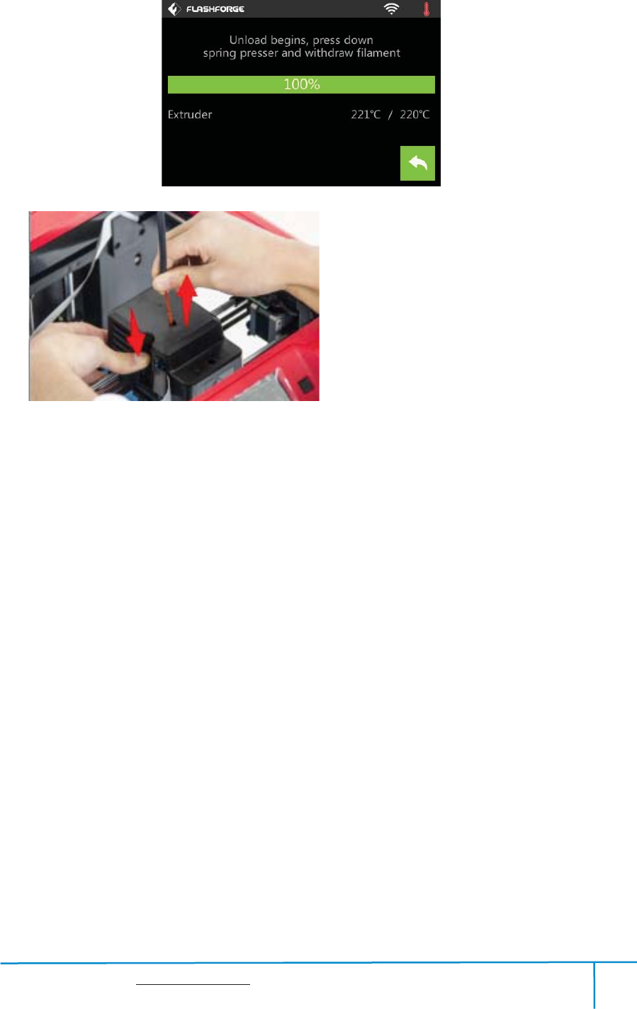
4-12
(4-12) After the extruder reaches 220 , the printer will sound a beep to prompt you to ć
unload the filament from the extruder. Press the spring presser, press down the
filament for about three seconds and gently pull the filament out.
Note: Do not pull out the filament with force as it will damage the gears. If the
melted filament has cooled down in the extruder, please repeat the steps above.
Finder User Guide | www.flashforge.com 0086-0579-82273989
30
Chapter 5: Build Plate Leveling
Finder creatively adopts three-point intelligent leveling system, which will give clear
and comprehensive feedback to users. There are three spring-loaded knobs under the
build platform. The distance between the plate and nozzle increases while tightening
the knobs. On the contrary, the distance reduces.
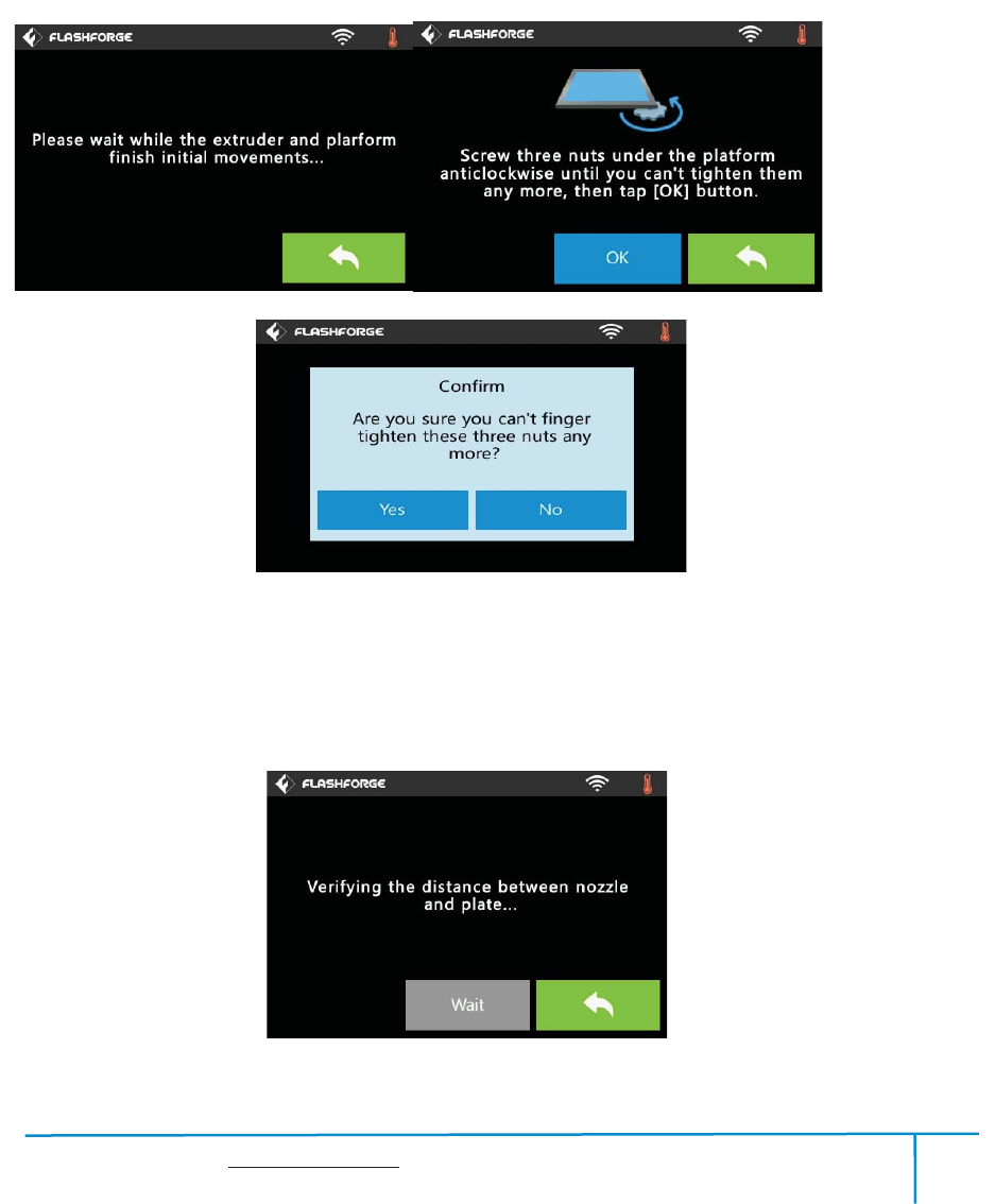
(5-1) Tap [Tools] - [Level] on your Finder touch screen. Please wait while the extruder
and platform finish initial movements. After that, operate according to the guide on the
touch screen.
5-2
51
Finder User Guide | www.flashforge.com 0086-0579-82273989
31
(5-2) After tapping [Yes], the extruder starts to move towards the first point and
theplate moves up and down to verify the distance between nozzle and plate.
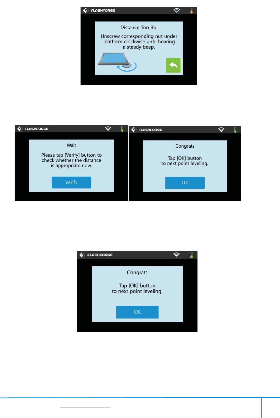
5-3
(5-3) When it shows that the distance is too big, please unscrew corresponding nut
under platform clockwise until hearing a steady beep and the [Verify] button appears.
5-4
(5-4) If the distance is appropriate, tap [OK] to second point leveling. If still not,
please follow the prompts to adjust again till you see [OK] button.
5-5
(5-5) Repeat steps 2 through 4 above to complete second and third points leveling and
then Tap [Finish] to exit.

Finder User Guide | www.flashforge.com 0086-0579-82273989
32
Leveling Emergency Plan
˖
Some levelingspare partsmay be damaged after being used for a period of time.
Now users could adopt the emergency plan for leveling.
˄1˅Insert the USB stick to the USB port.
˄2˅Tighten each of the three knobs underneath the build platform until they go no
further
˄3˅Tap [Build] on the touch screen, tap the USB icon and then select Leveling.g
file.
˄4˅Tap [Build], then the build plate and the extruder start moving.
˄5˅After they stop moving, you can adjust the distance between the build plate and
the nozzle manually. Move the extruder to the position right over the front-left knob,
and adjust the knob individually. Use a A4 paper to check the distance. As you adjust
the knob, make sure the paper just slides between the nozzle and build plate. There
will be somewhat friction on the paper but still can easily pass the paper between the
plate and the nozzle without tearing or damaging the paper.
˄6˅Then move to the positions right over the right-front and rear knobs successively,
and then adjust the distance according to the descriptions above.
˄7˅Then move to the center of the build plate for a check. Confirm that the paper
slides between the nozzle and build with a moderate amount friction.
˄8˅Tap the Abort button and finish leveling.
Finder User Guide | www.flashforge.com 0086-0579-82273989
33
Chapter 6: About Software
6.1 Software Installation
6.1.1 Software Acquisition
Method 1: To get the installation package from the USB disk in the toolkit.
Method 2: Open the link below to download the installation package:
http://www.flashforge.com
Steps:
Support---Downloads---Flashprint---chose the software version---download
6.1.2 Software Installation and Start-up
1. Decompress the zipped file or start the installation program, and then install the
software according to the direction.
2. Start the software with the start menu shortcut or by clicking the software icon.(See
6-1)
61
6.2 Exploring FlashPrint
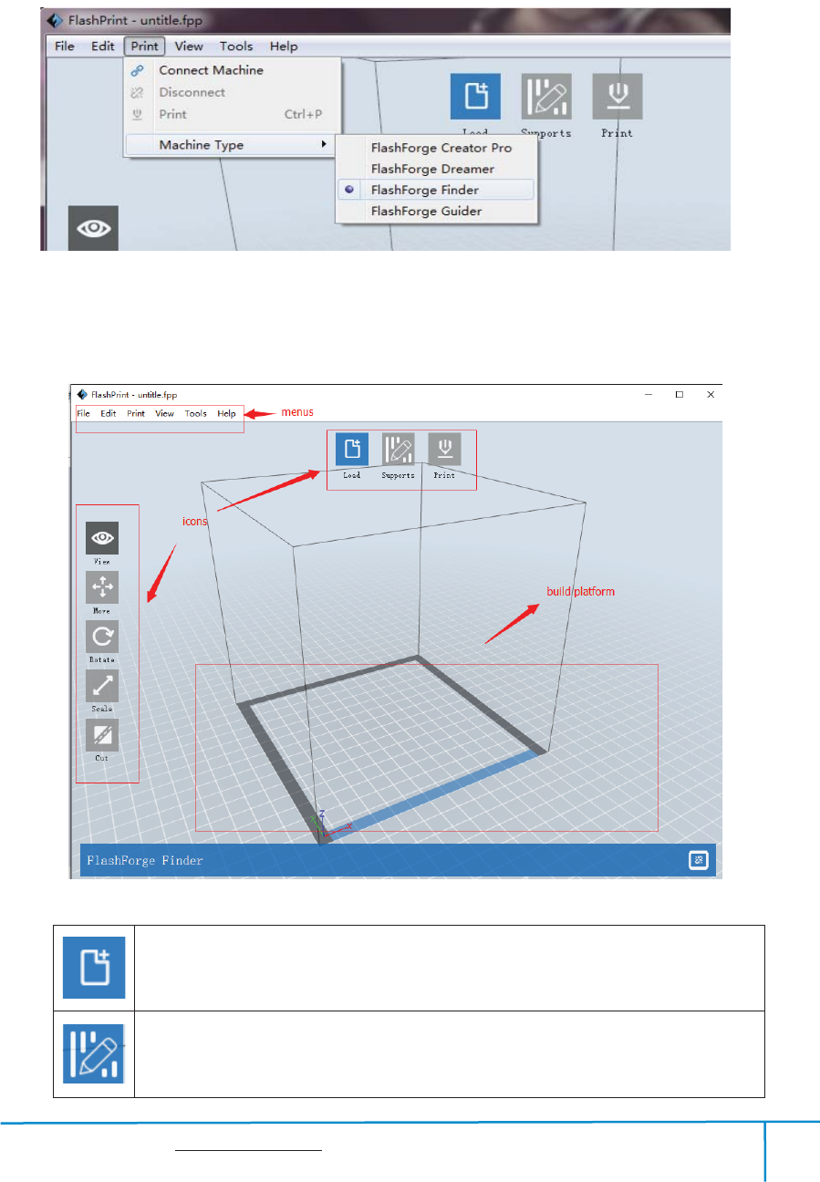
6. 2.1 Machine Type Selection
! After starting FlashPrint, you need to select the target machine type first.
Finder User Guide | www.flashforge.com 0086-0579-82273989
34
When you start FlashPrint, a dialog box will pop up. Just select Flashforge Finder in
the machine type list and click [OK]. You can also change the machine type via
clicking [Print]--[Machine type]. See graphic 6-2:
62
6.2.2 Software Introduction
Loadoneormultiplefiles.
Enterthesupporteditmode
63
Finder User Guide | www.flashforge.com 0086-0579-82273989
35
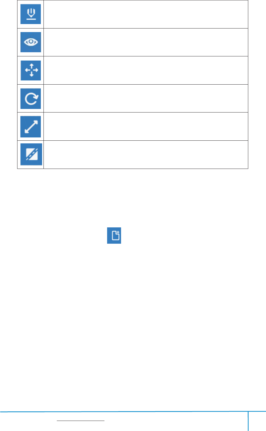
PrintitdirectlywithyourFinderorexporttoyourUSBStick
ViewFlashPrinthomescreenfromoneofsixviewingangles
Movemodelaroundonxyplane;shift+clicktomovealongzaxis
Turnandrotateyourmodel
Scalethesizeofyourobject
Cutmodelintoseveralparts
6.2.3 Loading
You can load a model file or Gcode file into your Flashprint by the following six
methods:
Method 1: Click the Load icon on the main interface. Then select the object
file.
Method 2: Select the file for loading and drag the file to the main interface of the
software.
Method 3: Click [File]--[Load File]. Then select the object file for loading.
Method 4: Click [File]--[Examples] to load the example files
Method 5: Click [File]--[Recent Files] to load the files opened recently.
Method 6: Select and drag the target file to the icon of Flashprint.
Note: .STL, .OBJ, and .FPP, ways to store 3D models, are supported by Flashprint
for editing.
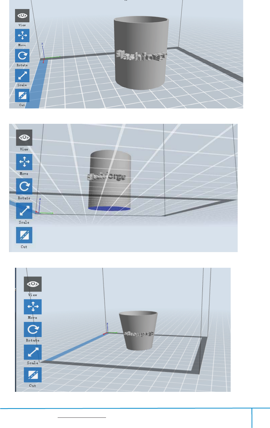
Generating Rilievo
Finder User Guide | www.flashforge.com 0086-0579-82273989
36
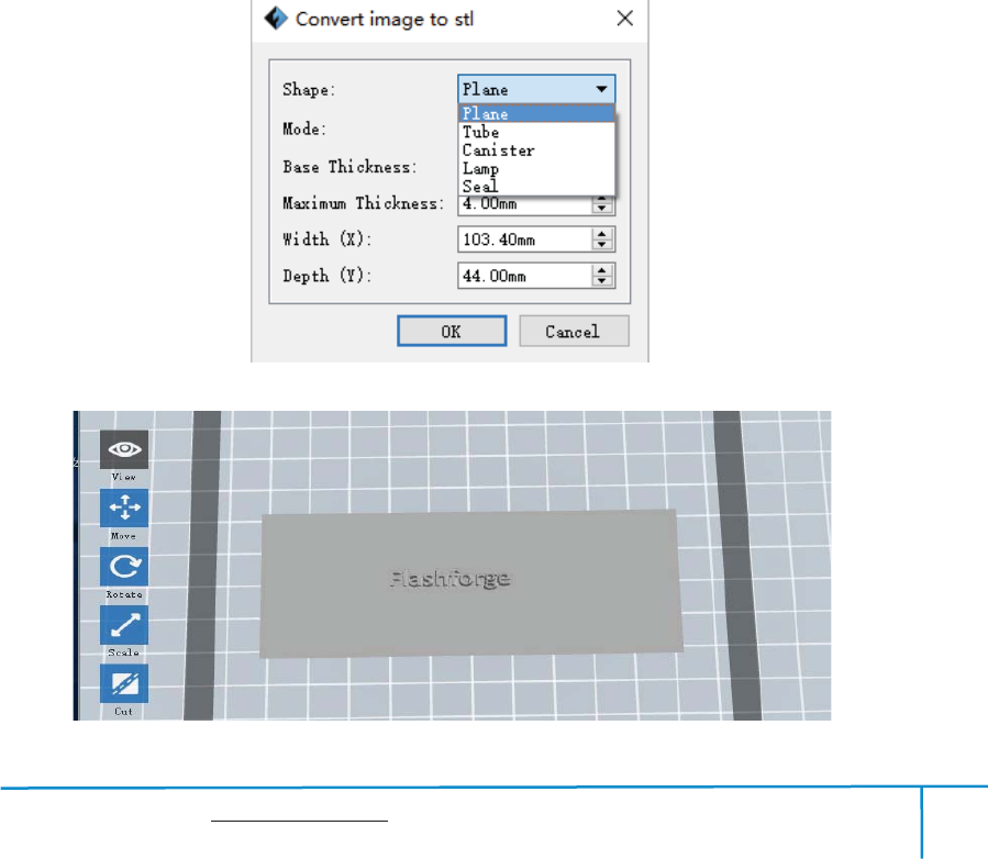
Loading a png, jpg, jpeg, bmp picture file into the FlashPrint. And the following
dialogue box(6-3) will pop up. The setting box includes settings for shape, mode,
maximum thickness, base thickness, bottom thickness,width, height, top diameter and
bottom diameter.
Shape: including plane, tube, canister and lamp.
Mode: including “darker is higher”and “lighter is higher”.
Maximum thickness: Z value of the model
Base thickness: The minimum raft thickness and the default value is 0.5mm
Width: X value of the model
Depth: Y value of the model
Bottom thickness: For tube, canister and lamp to set up bottom thickness
Top diameter: For tube, canister lampand steal to set up the top diameter
Bottom diameter: For tube, canister, lampand steal to set up the bottom diameter
64
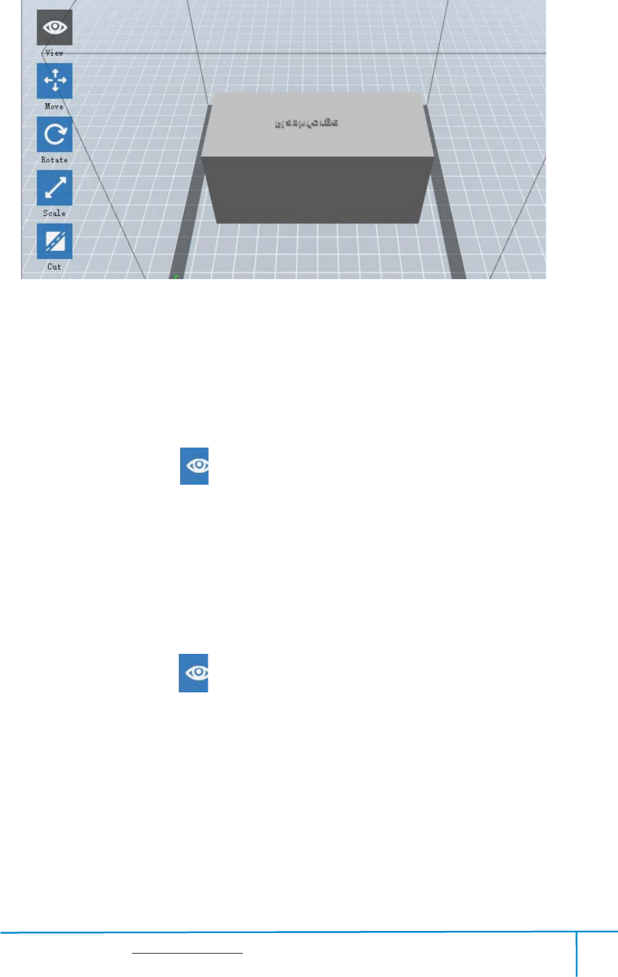
Plane(6-5)
Finder User Guide | www.flashforge.com 0086-0579-82273989
37
Tube˄6-6˅
Cansiter(6-7)
Lamp(6-8)
Finder User Guide | www.flashforge.com 0086-0579-82273989
38
Seal(6-9)
6.2.4 Views
Changing views
ķ
Change model views by moving, rotating, scaling.
Drag
Click the [View] icon and then you can move the object by the following three
methods:
Method 1: Hold down the left mouse button and drag.
Method 2: Hold down the middle mouse button and drag.
Method 3: Hold down theShift key, hold down the right mouse button and drag.
Rotate
Click the [View] iconand then you can rotate the object by the following two methods:
Method 1. Hold down the right mouse button and drag.
Method 2. Hold down theShiftkey, hold down the left mouse button and drag.
Scale
Rotate the mouse wheel to enlarge or shrink the build plate.

Finder User Guide | www.flashforge.com 0086-0579-82273989
39
ĸ
Set View
Allows users to view the object on the build plate. Six views are under the view menu,
that is, home view, bottom view, top view, front view, back view, left view and right
view.
Method 1: Click the the [View] button, there are six views in the drop- down list
Method 2: Click the the[Look] icon on the left, click it again and a submenu
will appear with six views for selecting.
Ĺ
Reset View
Allowuserstoresetviewsbythefollowingtwomethods:
Method 1: Click the [View] menu and select [Home View]
Method 2:Clickthe [View] button on the left, click it again and you will see the
viewing options, you can click [Reset].
ĺ
Show Model Outline
Click[View]--[Show Model Outline], it will highlight the yellow border ofthe object
Ļ
Show Steep Overhang
Click[View]--[Show Steep Overhang]. When the intersection angle between the
model surface and horizontal line is within the overhang threshold value, the surface
has steep overhang and it becomes red in the software. Overhang threshold value
could be set as needed. The default value is 45 degree.
6.2.5 Move
Select the object and move the object by the following two methods:

Finder User Guide | www.flashforge.com 0086-0579-82273989
40
Method 1: Click the [Move] icon on the left, hold down the left mouse button and
drag to adjust the location of the model in XY direction. Hold down the Shiftkey, hold
down the left mouse button and drag to adjust the location of the model in Z direction.
The distance and the direction of the movement shall be displayed.
Method 2: Click the [Move] button on the left and then enter the distance value. Click
[Reset]to reset distance values.
Note: Users shall click [Center] and [On Platform] after the location adjustment to
ensure the model(s) be within the build area and on the build platform. If a specified
position is needed, only to click[On Platform].
6.2.6 Rotate
Select the target object and rotate the object by the following two methods:
Method 1: Click the [Rotate] iconon the left and three mutually perpendicular rings
appear around the object Click one ring and rotate on the present axis, you will see the
rotation angle and direction in the center of circle. In this way, you could make the
model rotate on X/Y/Z axis.
Method 2: Click the [Rotate] icon on the left, and then enter into rotating angel
values in X/Y/Z axes positioning. Click [Reset] to reset rotating angel values.
6.2.7 Scale
Select the target object and scale the object by the following two methods:
Method 1: Click the [Scale] icon on the left, hold down the left mouse button and
scale the model. The corresponding values will display near the object.
Method 2: Click the [Scale] icon on the left and then enter into scale values in X/Y/Z
axes positioning. Click the [Maximum] button to get largest size possible for building.
Click [Reset] to reset the size of model.
Finder User Guide | www.flashforge.com 0086-0579-82273989
41
Note: If the[Uniform Scaling] radio button is clicked, it will scale the model in equal
proportion when changing value in any positioning of the model. Otherwise it will
only change the value of the corresponding positioning.
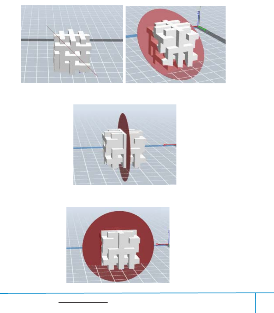
6.2.8Cut
Left-click on the model to select it and double-click on the Cut icon to set the cut
plane. The direction and position are available for setting.
Draw with Mouseķ
X Planeĸ
Y PlaneĹ
Finder User Guide | www.flashforge.com 0086-0579-82273989
42
Z Planeĺ
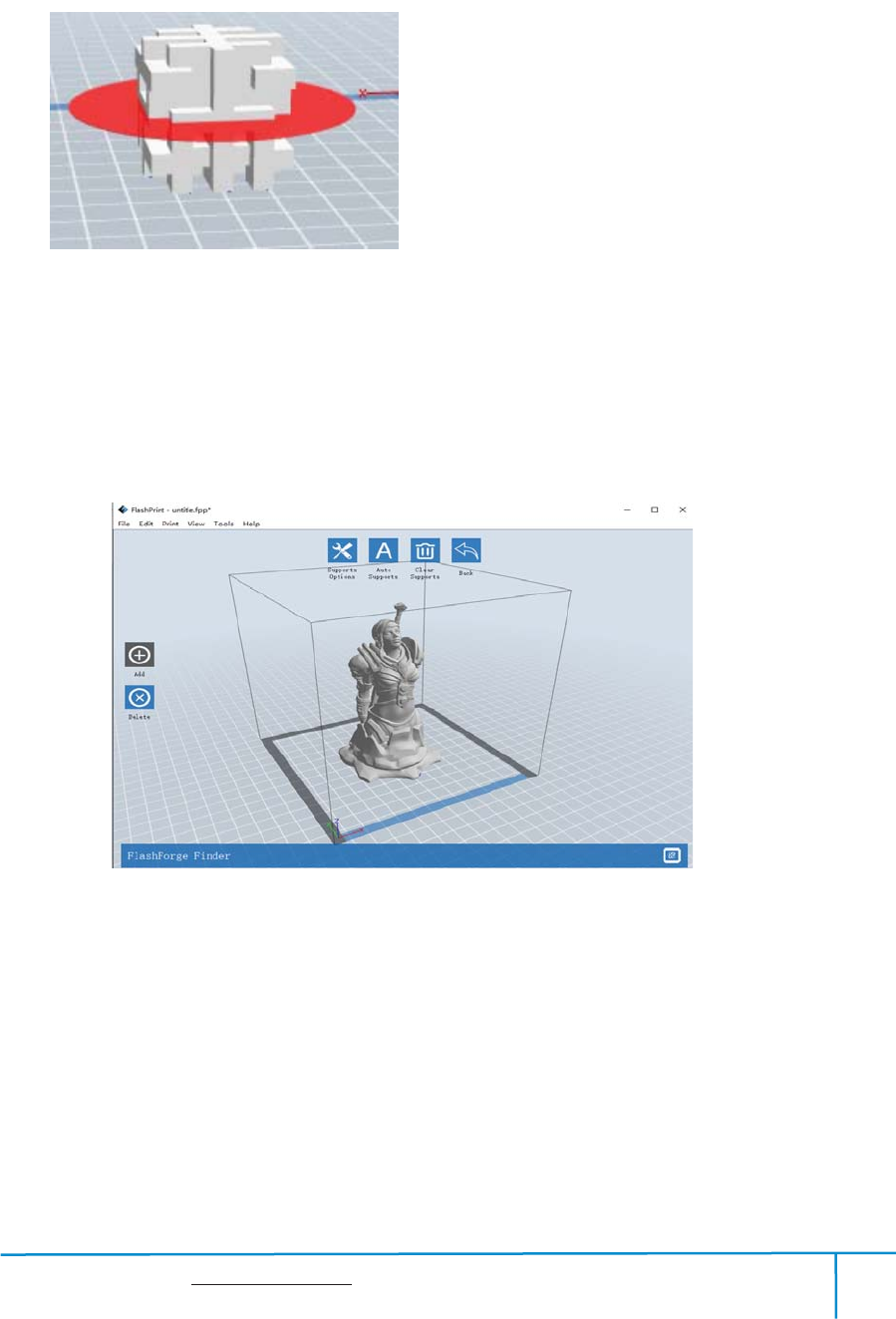
6.2.9 Supports
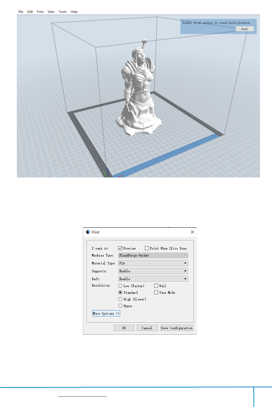
After loading the model, click [Edit]--[Supports] or click the Supports icon directly,
then you will enter the support edit mode(as shown in the picture below). Click [Back]
to exit when you finish editing.
6-10
Support Options
ķ
Click the Support Options, an option box will appear, supports options include
“treelike”and “linear”, when choose “treelike”, click [OK], then it will generate
treelike structure; when choose “linear”, click [OK], then it will generatelinear
structure; if it is a model with supports, when you choose one of the supports
options,software will judge whether existing supports need to be deleted or not on the
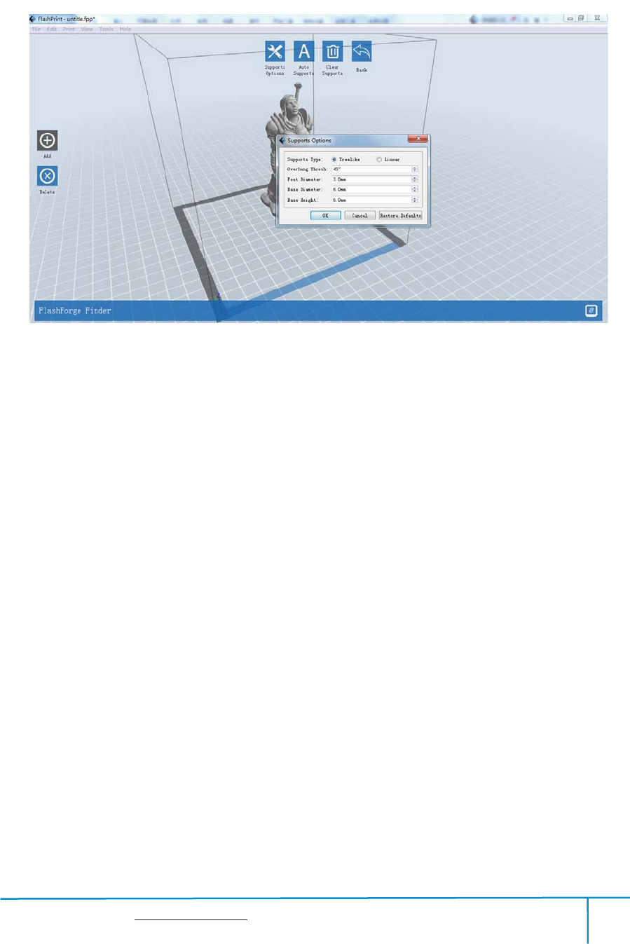
Finder User Guide | www.flashforge.com 0086-0579-82273989
43
basis of the type of existing support, and will pop up the corresponding prompt to let
you make the choice.
ĸ
Auto Supports
Click the [Auto Supports] button, the software will judge the position where supports
are needed and generate corresponding treelike or linear supports. If it is a model with
supports, the existing supports will be deleted and new supports will be generated.
Ĺ
Add Supports
Supports will be added once clicking the [Add] button. Move the cursor to the
position where supports needed, left-click to choose the starting point of supports, hold
down the left mouse button and drag the mouse the supports preview will show up(if
support surface doesn’t need support or the support column angle is too large, will
highlight the support review ).Loosen the left mouse button, if support column doesn’t
meet with model, then support will be generated on origin and terminal point(the
highlighted preview support won’t generate support structure )
6-11
Finder User Guide | www.flashforge.com 0086-0579-82273989
44
ĺ
Clear Supports
Click [Clear Supports], all supports will be deleted. The operation can be repealed
via clicking [Undo] or pressing the shortcut key Ctrl+Z.
Ļ
Delete Supports
Supports will be deleted once clicking the [Delete] button. Move the cursor to the
supports needed deleting, current supports and its subnode support will be highlighted,
click the left mouse button to delete these highlighted support.
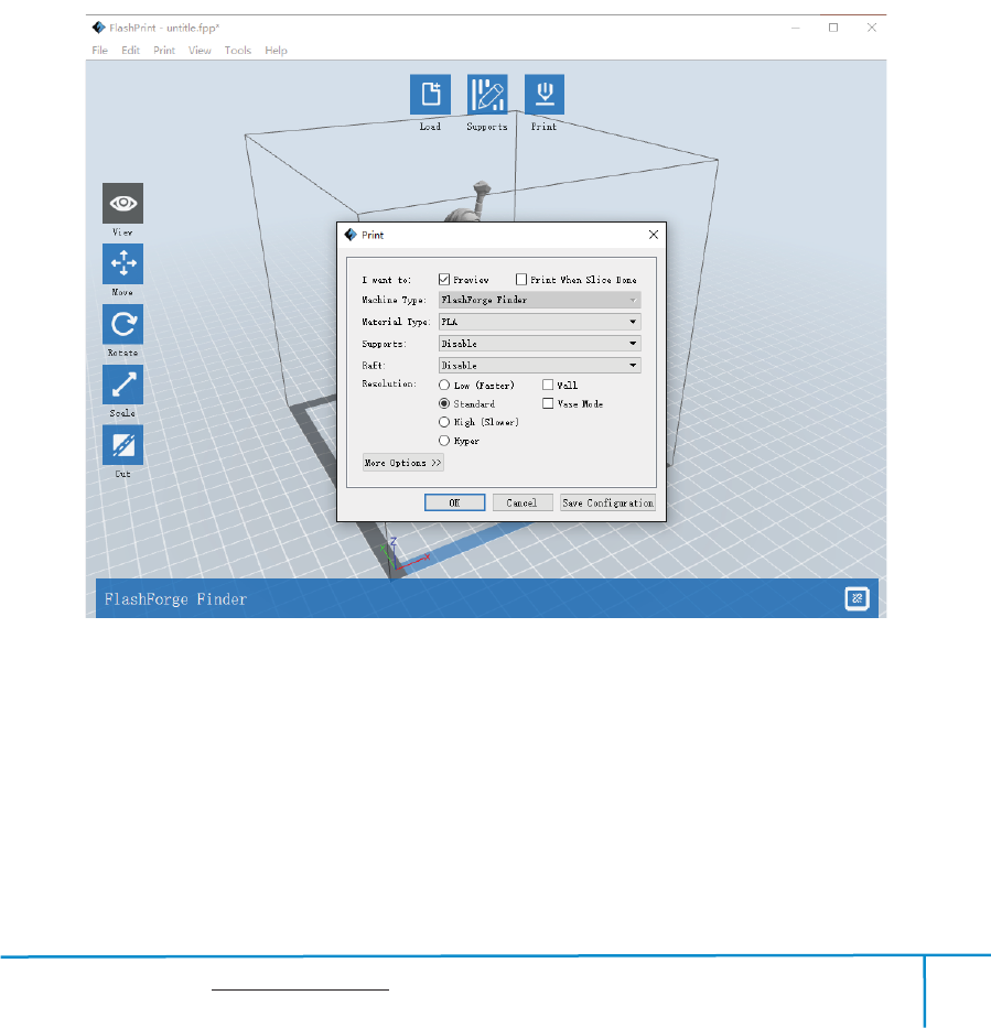
6.2.10 Print
Preview:
ķ
Choose to enter preview interface or not
Print when slice done:
ĸ
Print or not when slice done
Material type:
Ĺ
Choose according to the type of model
6-12

Finder User Guide | www.flashforge.com 0086-0579-82273989
45
Supports:
ĺ
When print suspended structure models, support is necessary. Click
[supports] to create support part for the printing.
Raft:
Ļ
This function will help the model to stick well on the platform.
Wall:
ļ
During dual color printing, this function will help to clear the leaking
filament of another extruder.
Vase Mode:
Ľ
No capping for the model
Resolution
ľ
You have three resolution solution(with default setting)to choose from,
high resolution is corresponding with slow printing speed, opposite for the low
resolution.For PLA printing, an extra solution “Hyper” is available.
More options:
Ŀ
Click [More options] to set for layer, shell, infill, speed and
temperature. Different resolution solution is corresponding to different defaults, click
[Restore Defaults] to back to default setting.
Layer
a. Layer: Layer thickness of the printing model. With a small value, the surface
of the model will be more smooth.
b. First Layer Height: This is the first layer of the model, which will affect the
sticking performance between the model and platform. Maximize is 0.4mm, usually
the default is ok.
c. Shell: Contains the outside shell value, capping layer value (under vase pattern,
top solid layer setting is invalid.)
Primeter Shells: Maximize is 10
a. Top Solid Layer: Maximize is 10, minimum is 1.
b. Bottom Solid Layer: Maximize is 10, minimum is 1.
Infill
a. Fill Density means fill rate.

Finder User Guide | www.flashforge.com 0086-0579-82273989
46
b. Fill Pattern is the pattern of filling shape which effects printing duration.
c. Combine Infill: You can select the layers for combining according to the layer
thickness. The combined thickness should not exceed 0.4mm. “Every N layers” is for all the
infills while “Every N inner layers” is only for inner infills, which generally can save print
time.
6-13
Speed
a. Print Speed is the moving speed of the extruder. Generally, the lower speed is,
the better print you will get. For PLA printing, 80 is recommended.
b. Support Print Speed is needed to set when choosing Slic3r as the
slice engine which can control the moving speed of the extruder when printing
the supports.
c. Travel Speed is to control the moving speed of the extruder under non-printing
Status during work. For PLA printing, 100 is recommended.
Note: Modify parameters settings to get better prints as different models need different
parameters.
Temperature
Extruder Temperature: Recommended extruder temperature is 220 .ć
Note: Different temperatures have subtle influences in prints. Please adjust the
temperature according to the condition in order to get a good print.
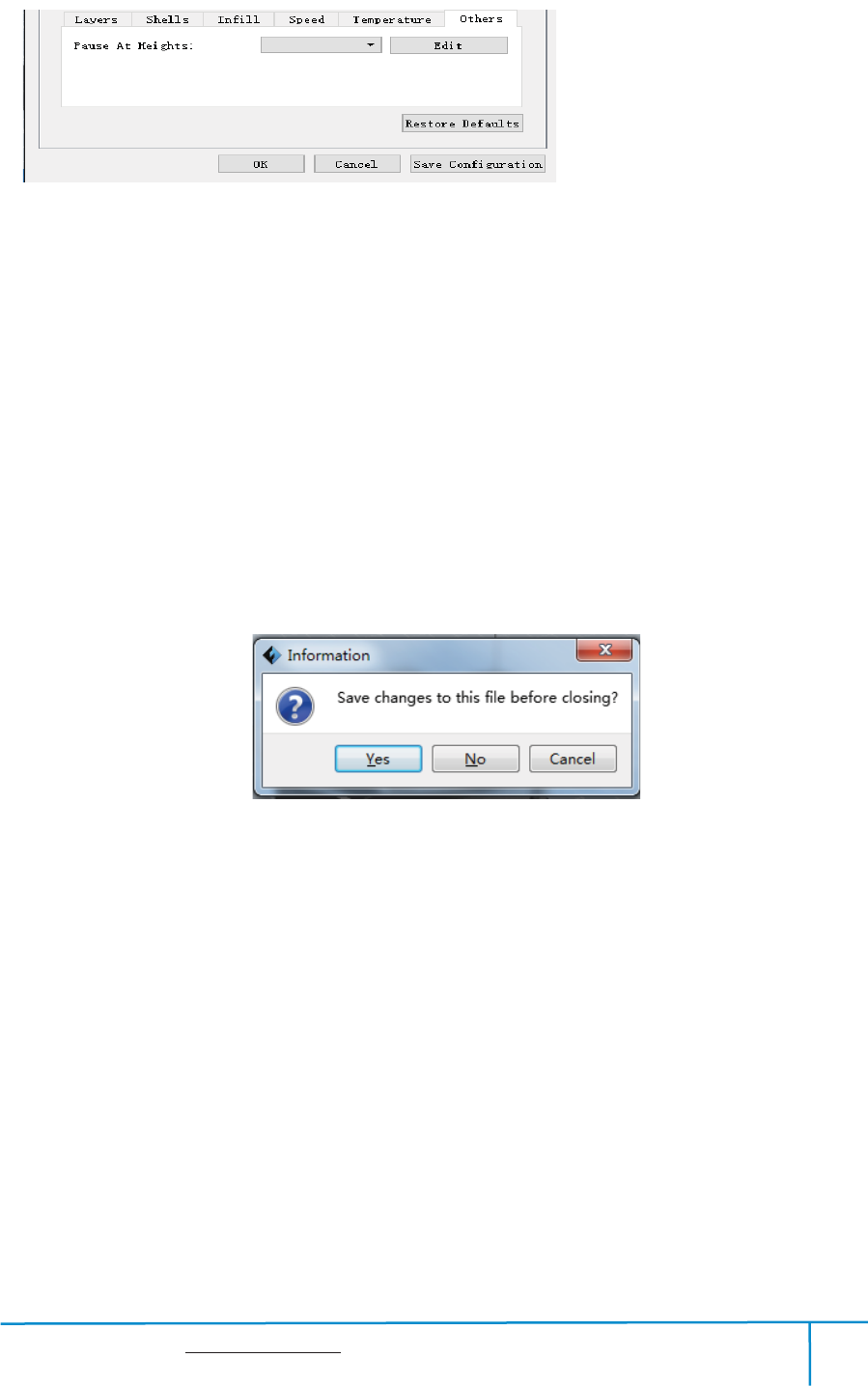
Others
Pause At Heights: Allows users to pre-set a height in which the print will suspend
automatically. The function usually applied when you want to change the filament at a
certain point.
Finder User Guide | www.flashforge.com 0086-0579-82273989
47
(6-14) Click[Edit], then you can add or remove a height.
6.2.11 File Menus
ķ
New Project
Click [File]--[New Project] can build a blank project. If there is an unsaved
modification on previous project, then it will inform you whether the modification
needs to be saved or not. Click [Ye s ] will save the modification, click [No] will
abandon it. If click [Cancel] or close tool tip, then will cancel the new project.
ĸ
Saving
After finishing the model edit and adjustment, there are two ways below to save all
models in the scene.
Method 1:
Click [File]--[Save Project] in the menu bar to save the file as a project file with the
“.fpp”suffix,all models in the scene (include support) are independent . After reloading
the files, extruder configuration information and model position will be the same as
the configuration during saving.
615
6-14
Finder User Guide | www.flashforge.com 0086-0579-82273989
48
Method 2:
Click on [File]--[Save as...] to save the model as project file .fpp or .stl and .obj.
For .stl and .boj, models are integrated as one(include support part). If load it again,
only the position of the model was saved, not included the printing parameters.
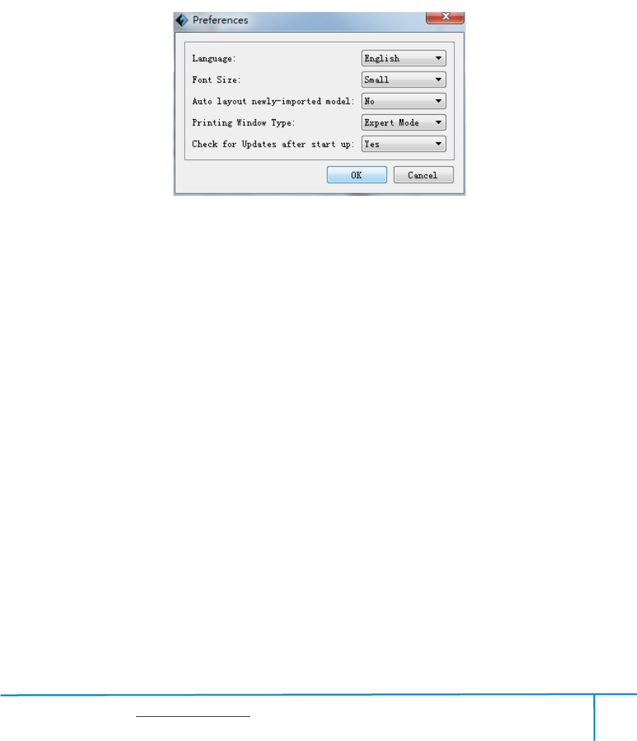
Ĺ
Preferences
Click [File]--[Preferences], you can choose language and if needs detecting update
when start
Language: The software supports six languages, namely, Chinese(simplified
Chinese and traditional Chinese), English, French, Korean, Japanese and Russian.
Printing Window Type: Including Base Mode and Expert Mode
Check for Update after start up: It is used to preset if it is necessary to activate the
online automatic update function, if choose yes, every time when you open software, it
can online detect if it is a new version software, once new version found, it will
reminds users to download and install new version firmware.
6.2.12 Edit Menus
ķ
Undo
Allows users to undo the recent edits by the following two methods:
Method 1: Click [Edit]--[Undo].
6-16

Finder User Guide | www.flashforge.com 0086-0579-82273989
49
Method 2: Press the shortcut Ctrl+Z.
ĸ
Redo
Allows users to redo the most recent edit you have undone to your model file by the
following two methods
Method 1: Click [Edit]--[Redo]
Method 2: Press the shortcutCtrl+Y.
Ĺ
Empty Undo-stack
To clean up the recorded operating steps so as to release the memory.
ĺ
Select All
By the following two methods, you could select all models in the scene. (When
models are too small to be seen or out of viewing scope, please click
[Center]and[Scale]buttons to adjust the model.)
Method 1: Click [Edit]--[Select All].
Method 2: Pressthe shortcut Ctrl+A.
Ļ
Duplicate
Select the object and duplicate the object through the following two methods:
Method 1: Click [Edit]--[Duplicate]
Method 2: Press the shortcut Ctrl+D
ļ
Delete
Select the object and delete the object through the following two methods:
Method 1: Click [Edit]--[Delete]
Method 2: Press the shortcut Delete
Ľ
Surface to Platform
Finder User Guide | www.flashforge.com 0086-0579-82273989
50
After selecting the model, you can make the model surface to platform via the
following operation.
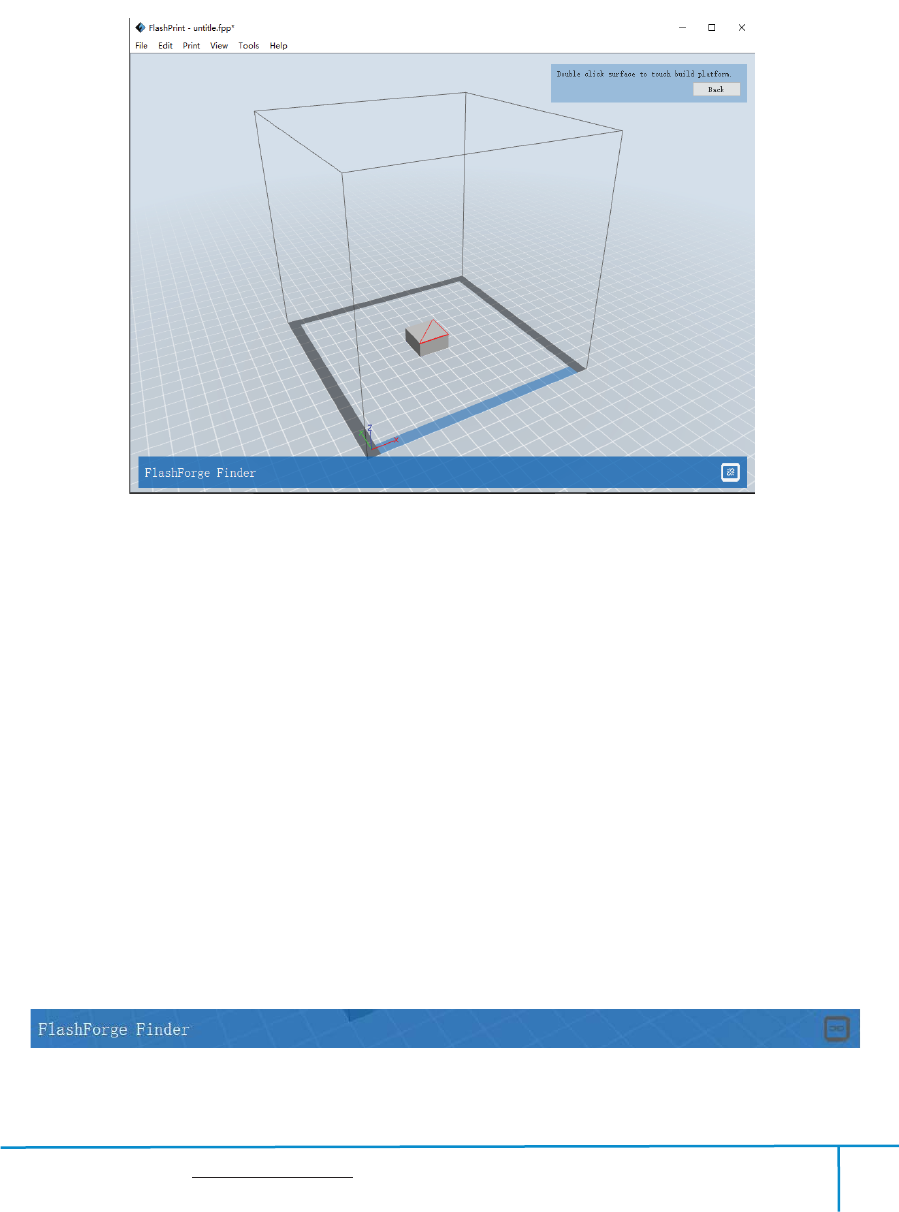
Click [Edit]--[Surface to Platform] into surface to platform mode(As
shown in the picture)
˄
SurfacetoPlatform
˅
ľ
Auto Layout All
Click [Edit]--[Auto Layout All] after loading one or more than one models, all
models will be placed automatically as automatic placement rule.
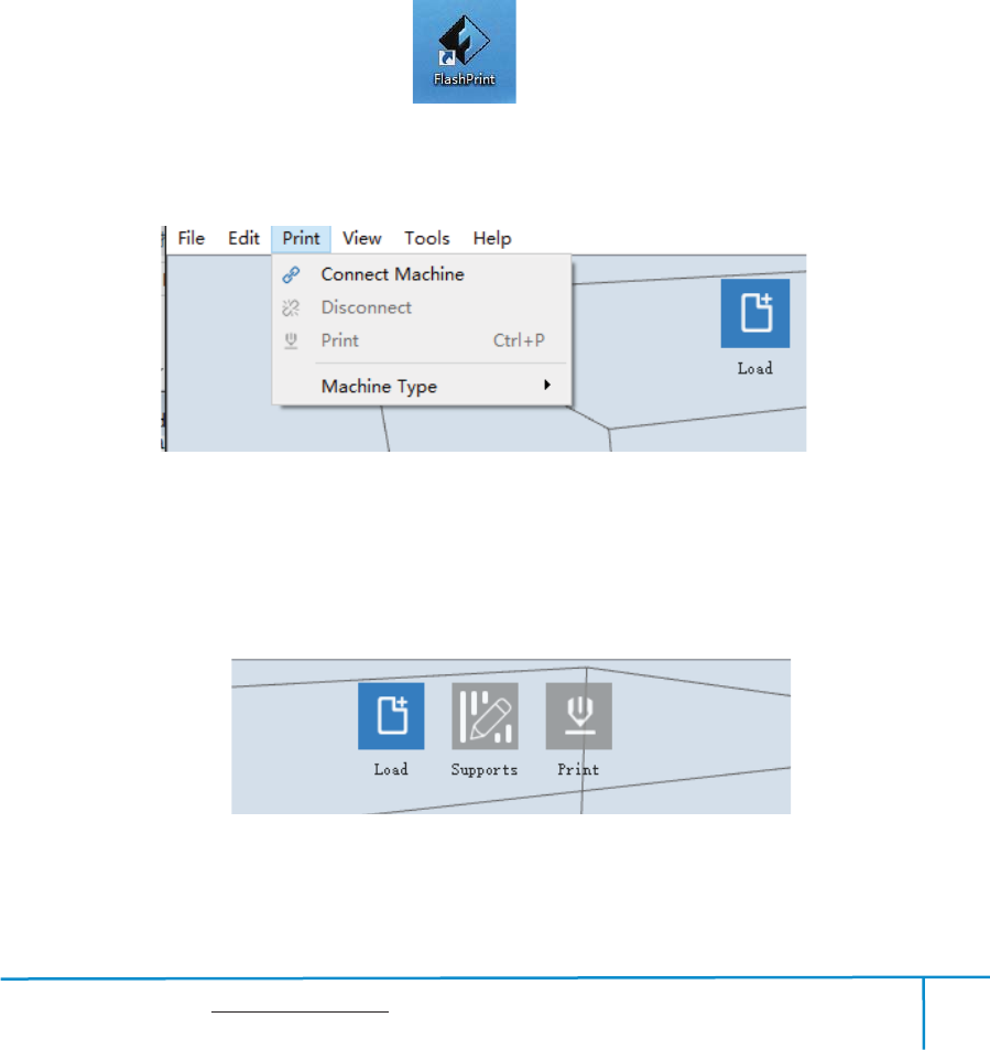
6.2.13 Print Menus
Connect Machine
ķ
You can connect the Finder with your PC via a USB cable or WIFI.
Note: The machine icon on the bottom right displays the connection status:
Connected
Disconnected
6-17
Finder User Guide | www.flashforge.com 0086-0579-82273989
51
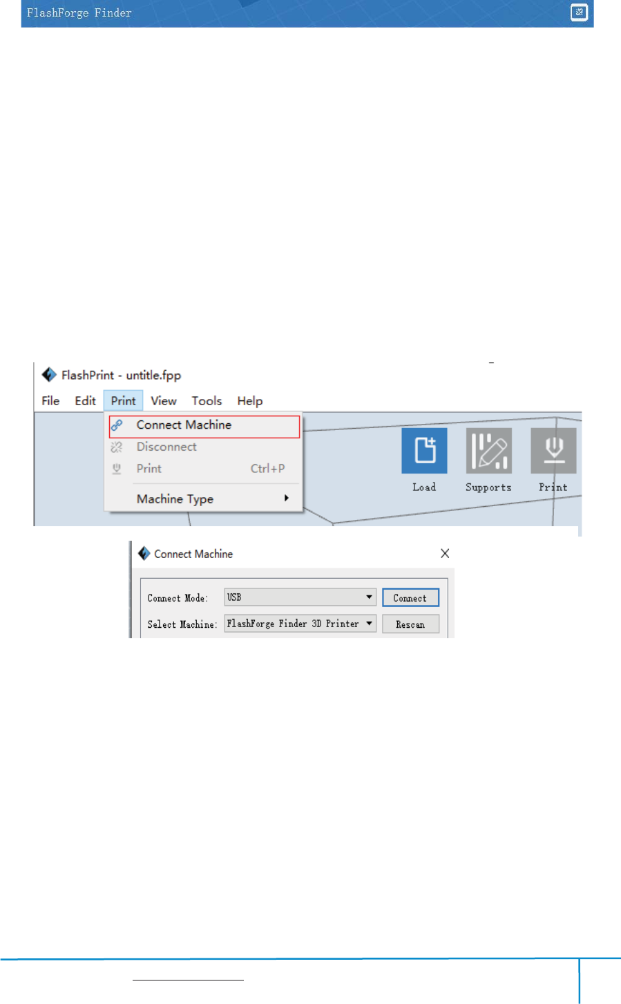
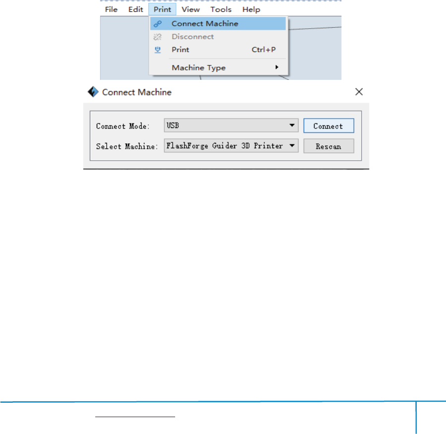
Method 1͵Connect Via USB Cable
a. Connect your Finder with your PC via an USB cable.
b. Turn on your Finder and start Flashprint.
c.Click [Print]--[Connect Machine], then select USB in the [Connection
Mode]option and select machine you want to connect in [Select Machine] option. If
you can not find your machine, click the [Rescan] button to scan your machine and
select it. Finally click[Connect] button to connect to the printer. If you still can not
find your machine after rescan, it means you haven’t installed the driver in the
software.
6-18
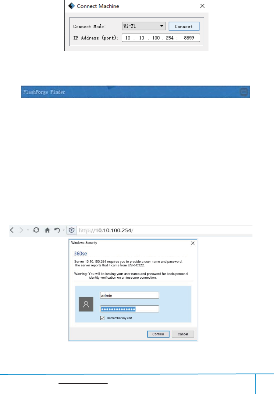
Method 2͵ Connect Via WIFI
Connect Finder with your PC under AP mode
ķ
a.Turn on your Finder
b.Tap [Tools]-[Setting]-[WIFI]-[WIFI ON]
c. Click on the wireless network on the left bottom, and find the wireless
signal-“Finder”. Click [Connect] to finish network connection.
d. Click[Print]-[Connect Machine] on Flashprint. Then the following dialog box
Finder User Guide | www.flashforge.com 0086-0579-82273989
52
pops up. You need to select “Wi-Fi” in Connect Mode. Enter into the IP Address
shown on the interface and then click [Connect].
6-19
If successfully connected, you will see the following red mark.
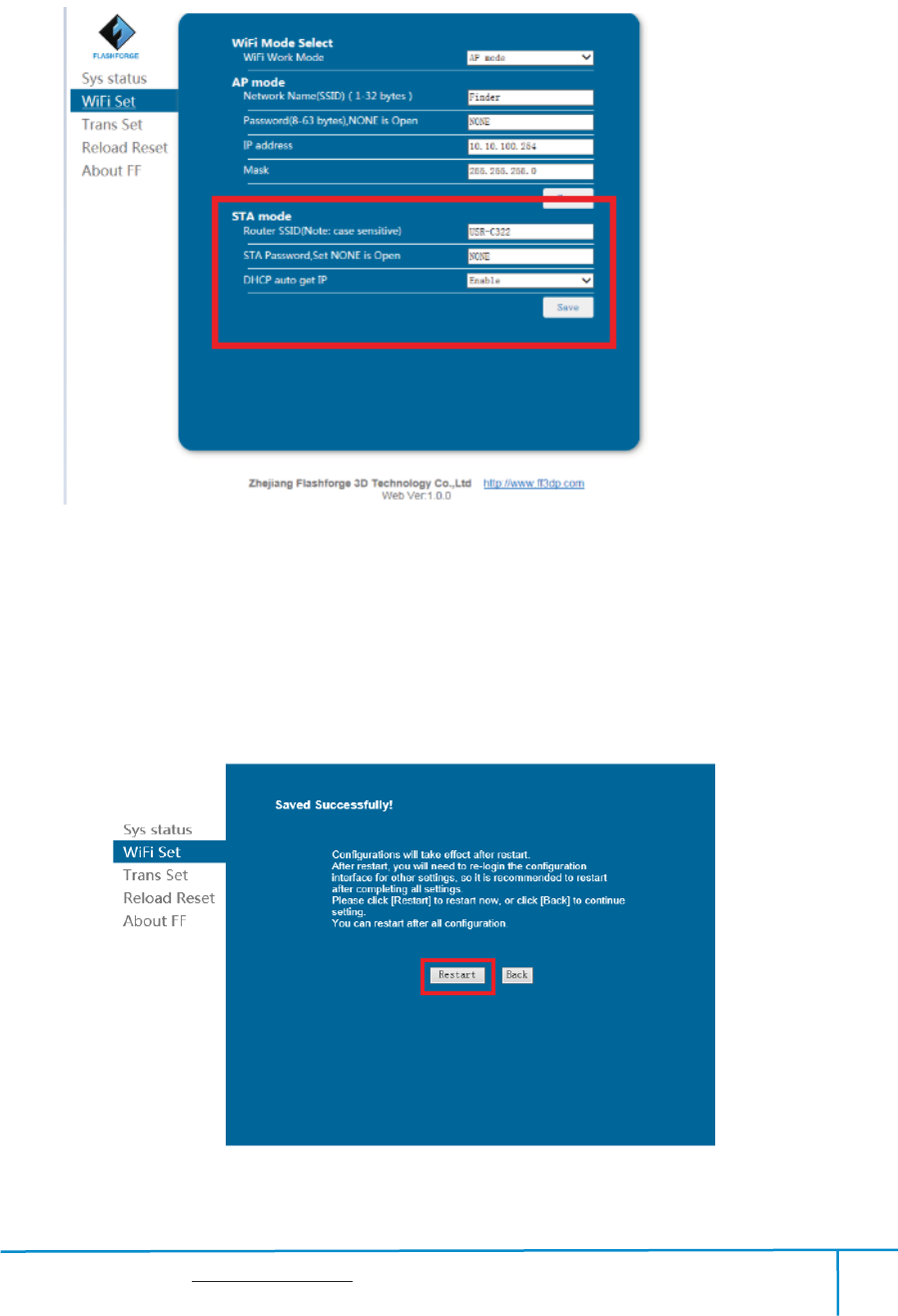
Connect Finder with your PC under STA mod
ĸ
e
a. Turn on the WIFI of Finder and connect your PC with Finder via the WIFI. Press
[ Tools ], [ Setting ], [ WIFI ],and [ WIFI ON].
b.“Finder” continuous signal will be found available on the network list.
c. Once your PC is connected with your Finder. Open the Internet browser and
enter “10.10.100.254” and enter the default user name(admin) and
password(admin).
620
e You will enter the WIFI setting panel, it displays as follows:
Finder User Guide | www.flashforge.com 0086-0579-82273989
53
621
d. Select WIFI mode as STA mode, and then complete the corresponding setups, you
can change the SSID(the WIFI’s name) and the password, select[Enable] in DHCP
auto get IP, then click [Save]. The following interface will appear.
6-22
Finder User Guide | www.flashforge.com 0086-0579-82273989
54
e. Click the [Restart] button. You need to restart your Finder’s WIFI. And then your
Finder will connect with your computer via the WIFI that you’ve set up.
Disconnect Finder
ĸ
Click[Print]--[Disconnect] to disconnect your PC and Finder.
6.2.14 Tool Menus
ķ
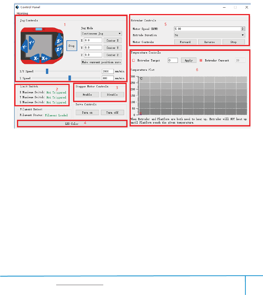
Control Panel
After connecting PC with Finder, click[Tools]--[Control Panel] to open the control
panel.
6-23
Jog Controls
a. Jog Mode
˖
Select the distance that extruder/build plate move a single time (that is,
the distance extruder/build plate move upon your single click).
b. Six blue arrow direction button: Control the move along X/Y/Z axis. X/Y axis
button control extruder move, Z axis button control build plate move. Click X-,
extruder will move leftward a specified distance; Click X+, extruder will move a
specified distance rightward. Click Y-, extruder will move forward a specified distance;
Click Y-, extruder will move backward a specified distance. Click Z-, build plate will

Finder User Guide | www.flashforge.com 0086-0579-82273989
55
move upward a specified distance; Click Z-, build plate will move downward a
specified distance. (Specified distance refers to the move distance you set in Jog
Mode.
c. Stop: Click the [stop] button to abort the current movement.d. XYZ coordinate
frame on the right side: Show the current position of extruder/build plate.
e. Make Current Position Zero button: Set the current position of the
extruder/build plate as (0, 0, 0). (NOTE: X, Y, and Z boxes are for display purposes.
Changing the value in the boxes will not affect anything.
f. Center X/Y/Z button: Extruder and build platform will back to the zero (0, 0, 0)
you set last time.
g. X/Y Speed and Z Speed: Set the move speed of extruder/ build platform.
Limit Switch: In order to protect your Finder, three limit switches are equipped to
control the maximum position, and the three limit switches corresponding to X/Y/Z
axis limit switch. It has two status:
a. Not Triggered: If the extruder/build plate don’t move to its maximum, X/Y/Z axis
limit switch is not triggered, and shows “Not Triggered”.
b. Triggered: If the extruder/build plate moves to its maximum, X/Y/Z axis limit
switch is triggered, and shows “Triggered”.
Stepper Motor Controls: Allows users to control to stepper motor. Click [Enable],
and lock the motor so it does not allow any movement; click [Disable], and unlock the
motor tobe controlled manually.
LED Color: Allows users to change the LED color of Finder.
Extruder Controls: You can set the value of “Motor Speed(RPM)”, which can
control the rotation speed of filament feeding wheel. The motor rotation time can be
controlled via setting the value of “Extruder Duration”.Generally we suggest the
users choose option of continuous time 60 seconds. The filament must loaded in the
Finder User Guide | www.flashforge.com 0086-0579-82273989
56
extruder before motor starts. Therefore, do not start rotation operation until the
extruder temperature reachesto the printing temperature of filament.For PLA
filament, the extruder temperature should reach 200 , after reaching the extruder ć
temperature, click the [Forward]/[Reverse]rotation button to control filament load
and filament unload. Furthermore, if you want to stop filament load and unload, you
can click[Stop].
Temperature Control: Input the temperature you want to get in the left frame,
click[Apply], the printer will automatically heat the corresponding part, the right side
shows the current actual temperature of corresponding part. After starting heating, the
below curve of temperature form will start to change, different color correspond
different parts’ temperatures
ĸ
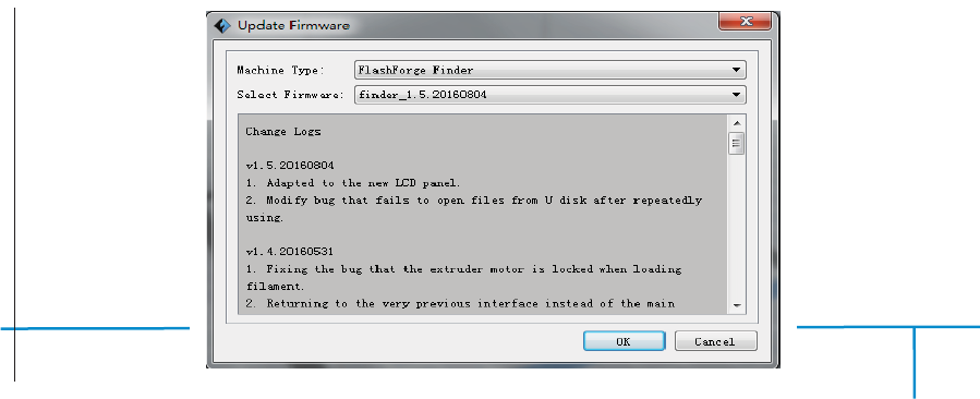
Update Firmware
Every time when you start Flashprint, it will automatically detect and download the
up-to-date firmware. If any update is available, a dialog box will pop up for reminding
the users to update.
Step 1: Click [Tools]--[Update firmware]. It needs to cut off connection before
updating firmware. If software and printer are already in connection, it reminds you
cutting off the connection, choose [Yes] and go on to the next step.
Step 2: Choose corresponding printer type and firmware version and click [OK] in the
firmware updating box. After confirming the printer is in free state, the software will
automatically update the firmware
Finder User Guide | www.flashforge.com 0086-0579-82273989
57
6-24
Step 3
˖
Reboot you Finder and wait for 4-5 seconds, then you can see the update
process bar. When the update finishes, it will go back to the main interface.
Step 4
˖
Tap[Tools]--[About] to check] to check whether the updated version is right.
Ĺ
On Board Preferences
When the computer and printer are in connection, click[Tools]--[On Board
Preferences], you can check the printer name.
ĺ
Machine information
When the computer and printer are in connection state, click [Tools]--[Machine
information], you can check the machine type, machine name and firmware etc.
6.2.15Help Menus
Help Contents
ķ˖
Click [Help]--[Help Contents], you can read the help contents.
Check for Updates
ĸ˖
Click[Help]--[Check for Update] to detect the available
updates online.
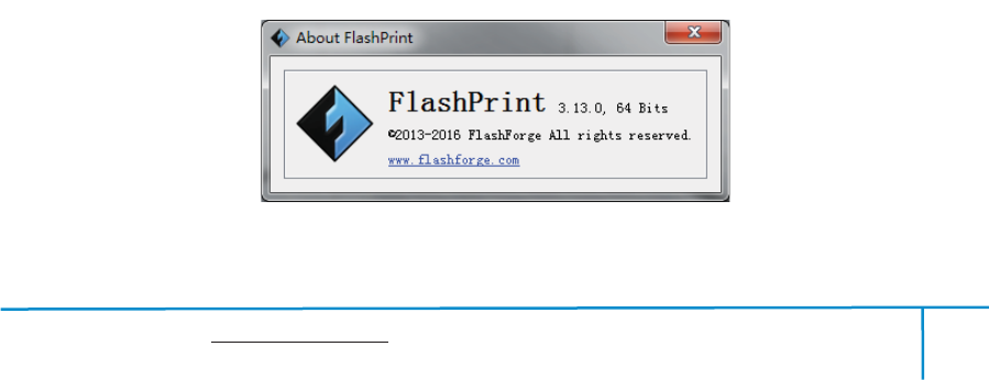
About FlashPrint
Ĺ˖
Click [Help]--[About Flashprint], the software information
box will pop up. The contents include the current software version and copyright
information.
6-25
Finder User Guide | www.flashforge.com 0086-0579-82273989
58
Chapter 7:Basic Printing
This chapter will provide a step-by-step guide on turning a 3D modelinto a physical
reality. Before proceeding, it is recommended that you’d bettergo over prior chapters on
loading/unloading filament, leveling the build platform, and the functions and
capabilities of FlashPrint.
7.1 Generate a Gcode
(7-1)Double-click the icon of Flashprint to start the software.
7-1
(7-2)Click[Print]--[Machine Type] to select Flashforge Finder
7-2
(7-3)Click the [Load] icon to load a .stl model file and the object will display on the
build area.
7-3
˄7-4˅Click[Edit]--[Surface to Platform] to make your model perfectly positioned
34
Finder User Guide | www.flashforge.com 0086-0579-82273989
59
on the build area. Click[Back]and double-click the Moveicon again, then click [On
the Platform] and [Center]to ensure the model be on the platform.
7-4
Note
˖
If you’ve place your model in a right place, you can skip the step above.
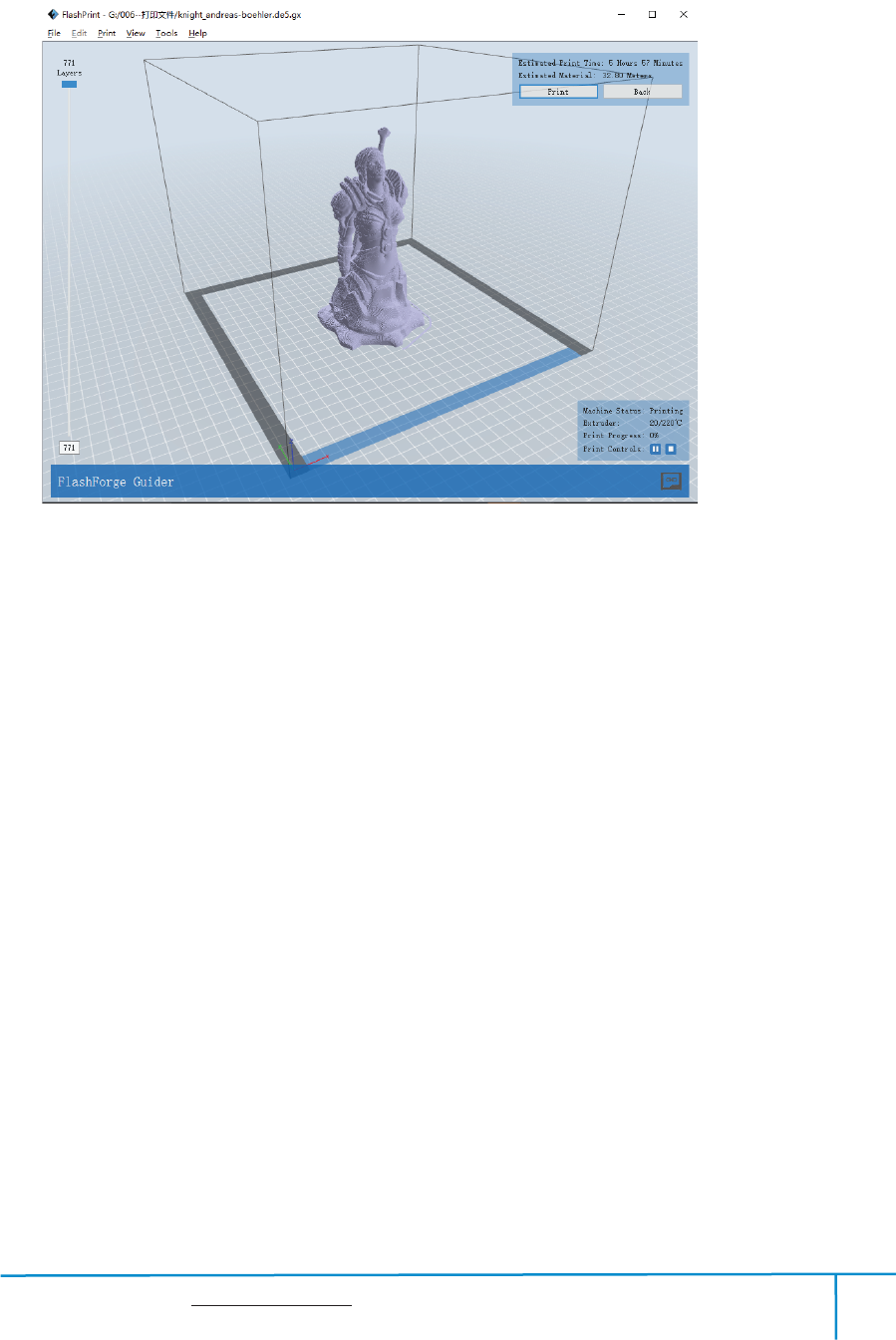
(7-5) Click the Print icon on the top, you should make some setups for your print job.
Preview: If you check the [Preview] box, you can preview your model after slicing is
done.
7-5
Finder User Guide | www.flashforge.com 0086-0579-82273989
60
Print When Slice Done: If you print via USB cable, you can check the box, while if
you print via USB, you should not check the box.
Machine Type: Flashforge Finder
Supports: If you print a model with supports, you should click the inverted triangle
and select [Enable].
Raft: You are suggested to select [Enable].
Resolution: You are suggested to select [Standard]
More Options: You are suggested to keep them default.
Click[OK] to select the path to save the Gcode file. You can rename the file as you
like and save it as a .g or .gx file, click [Save] to generate a Gcode file.
7-6
Note: .gx files are available for preview while the .g files are not. They are displaying
as follows:
g. Files gx. Files
7-7
Finder User Guide | www.flashforge.com 0086-0579-82273989
61
Next, we are going to print the model.
7.2 Print Methods
After generating the Gcode file, you can transfer it to your Finder. You can transfer the
file through USB cable and USB stick.
7.2.1 Print from Computer (USB connection)
Connect your Finder with your PC ķvia a USB cable.
Turn on your Finder, level the build plate and load the filament.ĸ
ĹClick [Print] and transfer your Gcode file to your Finder. After completing
transference, the printer will heat up automatically. And when heating finishes, the
print will start to build the model.
78
ĺWhen your PC connects with FlashPrint successfully. The status box on the
bottom right displays the real-time nozzle temperature. After finishing preheating,
your Finder starts the print job directly.
7.2.2 Print from Computer (WIFI connection)
Connect your Finder with your PC via WIFI.(Please refer to 6.1.13)ķ
Turn on your Finder, level the build plate and load the filament.ĸ
ĹClick [Print]and transfer your Gcode file to your Finder. After completing
Finder User Guide | www.flashforge.com 0086-0579-82273989
62
transference, the printer will heat up automatically. And when heating finishes, the
printer will start to build the model.
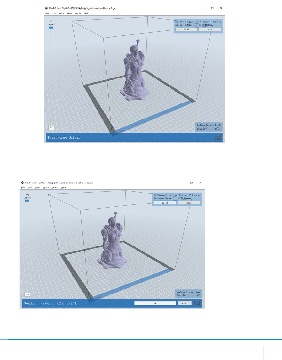
If you want to print a Gcode from a local folder, you just need to load the file into
Flashprint at the status of USB connection or WIFI connection, then click the [Print]
button on the top-right.
Load the target Gcode file into FlashPrint.
7-9
Click the [Print]button, the PC will transfer the Gcode file to the printer.
710
Finder User Guide | www.flashforge.com 0086-0579-82273989
63
After finishing transferring, the printer will heat up automatically. And when heating
finishes, the print will start to build the model.
7.2.3Print from USB Flash Disk
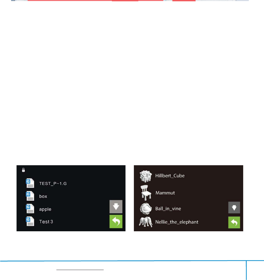
ķInsert your USB flash disk with target .g or .gx file to your Finder. .
ĸTurn on the Finder. Make sure the build plate has been leveled and the filament is
loaded.
ĹTap[Print]and then tap the SD Card icon in the middle. The file(s) will be displayed
on the screen.Select the file you want to print and tap[Print]. The file will be
transferred to the printer.
ļAnd the printer will heat up the nozzle automatically and start to print after the
nozzle reaches the aimed temperature.,
Abort
˖
To stop heating and printing. Once you tap [Abort], the process is irreversible.
Pause
˖
To suspend the print job, you can tap it again to resume it. You can use this
function when you want to change the filament halfway.
7-11
Finder User Guide | www.flashforge.com 0086-0579-82273989
64
Chapter 8: Advanced Printing
When you get familiar with your Finder, you will definitely want to accomplish some
advanced prints. This chapter will take you to get to know the advanced printing skills.
Expert Mode grants the users more freedom of parameter edition. There are two
modes are available for users, one is “Basic Mode” and the other is “Expert Mode”.
8-1
Select Profile: Allows users to select the required scheme. There are three options for
users (low/standard/high/high) and the default is PLA standard. Different schemes
correspond to different parameter settings. High-quality scheme produces
high-resolution object but at a low speed. On the contrary, low-quality scheme
produces low-resolution object but at a high speed. When printing with PLA, users
will find a “hyper” option available.
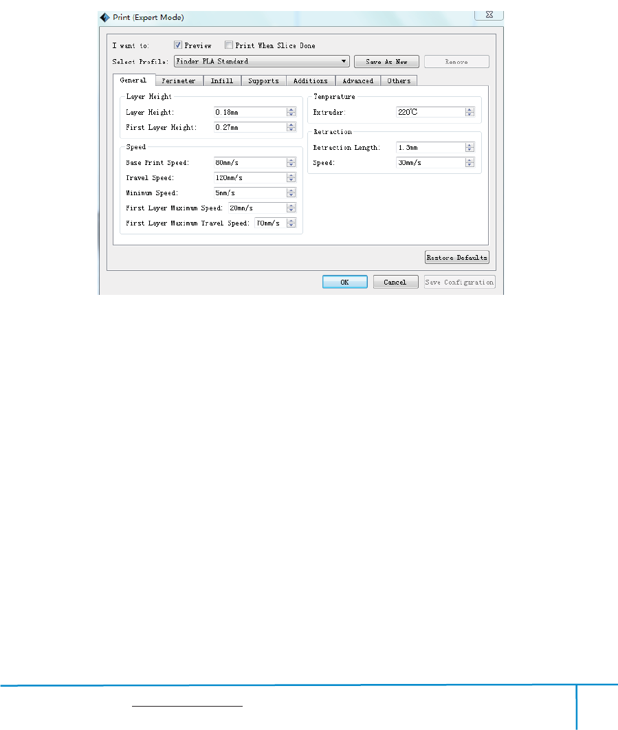
General:
a. Layer Height
Thickness of each layer. The less thickness of layers, the more time will be used and
the better model will be printed.
Finder User Guide | www.flashforge.com 0086-0579-82273989
65
b. First Layer Height
When printed with thinner layers, comparative thicker bottom layer could improve
adhesion and tolerance for non-perfect build plates.
2˅Speed
a. Base Print Speed: The fiducial value of extuder’s movement speed during
printing(For subsequent speeds counting ). With a lower speed, the printer can build an
objects with higher resolution and more smoothness.
b. Speed at which extruder moves when not extruding filament.
c. Minimum Speed: The minimum extruder’s movement speed during printing
d. First Layer Maximum Speed: The max printing speed for printing the first
layer(Note: It’s invalid to the model which has a raft )
e. First Layer Maximum Travel Speed: The max travel speed for printing the first
layer(Note: It’s invalid to the model which has a raft )
3˅Temperature
It displays the temperature of “Extruder”.
4˅Retraction
a. Retraction Length: Amount of retraction. Retraction can help users reduce stringing
or oozing during printing. (The default value shall be suggested.)
b. Speed: Speed at which the filament is retracted. The default value shall be
suggested.
8 -2
Finder User Guide | www.flashforge.com 0086-0579-82273989
66
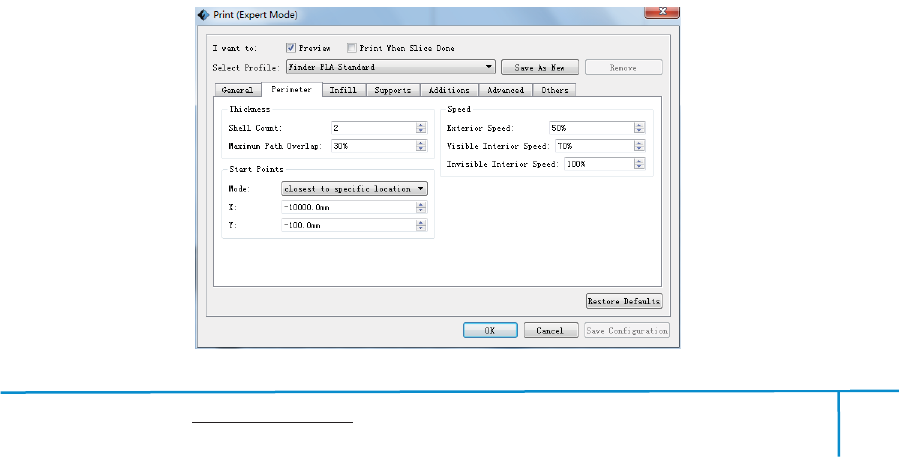
Perimeter
1˅Thickness
a . Shell Count: Numbers of laps for each layer’s shell. Maximum: 10; Minimum: 1.
b. Maximum Path Overlap: Max amount of overlapping extrusion for some models,
especially small models.
2˅Speed:
a. Exterior Speed: Speed at which the exterior shell is printed.
b. Visible Interior Speed: Speed at which the visible interior shell is printed.
c. Invisible Interior Speed: Speed at which the invisible interior shell is printed.
3˅ Start Points
a. Mode: There are two options for Start Point mode. One is “closest to specific
location”, the other is “use random start points”.
b. X: The coordinate value of X
c. Y: The coordinate value of Y
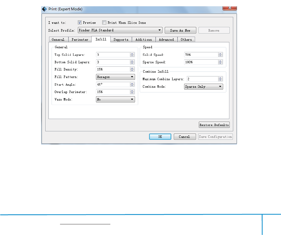
Infill
General
a. Top Solid Layer: Number of solid layers on the upper surface of model.
8-3
Finder User Guide | www.flashforge.com 0086-0579-82273989
67
b. Bottom Solid Layer: Number of solid layers on the under surface of model.
c. Fill Density: Determines the interior solidity of the model.
d. Fill Pattern: Determines the infill pattern used for the interior of part, Hexagon infill
has higher strength and Line infill take less print time.
e. Start Angle: Angle of the infill’s first layer
f. Overlap Perimeter: The overlap width between the infill and the shell.
g. Vase Mode: When enabled, the interior infill and top solid infill will not
printed.(Using this option will force 0% infill with only a single perimeter)
2) Speed
a . Solid Speed: Speed at which the top/bottom parts are printed.
b. Sparse Speed: Speed at which the infill is printed.
3˅Combine Infill
a. Maximum Combine Layers: Select the layer amount according to the layer height.
The total height shall not be over 0.4mm.
b. Combine Mode: Including “Sparse and Solid” and “Sparse Only”. “Sparse Only”
mode only applies for the inner infill layers.
8-4
Finder User Guide | www.flashforge.com 0086-0579-82273989
68
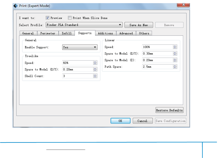
Support
1˅General
a. Enable Support: Allows users to turn on/off the support option. Support structure
can prevent the model from collapsing. If choosing “Yes”, then both treelike and linear
supports are available for setting up. If choosing “No”, then both treelike and linear
supports are unavailable for setting up.
2˅Treelike
a. Speed: Speed at which the treelike supports are printed.
b. Space to Model(X/Y): The gap between the treelike supports and the model contact
surface (in the X/Y directions).
c. Shell Count: To control the printing laps for support’s outer shell.
3˅Linear
a. Speed: Speed at which the linear supports are printed.
b. Space to Model(X/Y): The gap between the treelike supports and the model contact
surfaces (in the X/Y directions).
c. Space to Model(Z): The distance between the treelike supports and the model
contact surface (in the Z direction).
d. Path Space: The distance between the adjoining paths.
8-5

Finder User Guide | www.flashforge.com 0086-0579-82273989
69
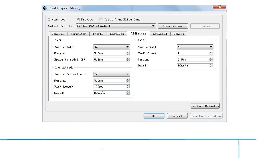
Additions
1˅Raft
a . Enable Raft: Enable to print raft during printing. Raft could help the model stick to
the build plate.
b. Margin: The distance between raft’s outline and outline of model’s first layer. If the
raft is enabled, the extra raft area around the object is also enabled. Increasing the
margin will create a stranger raft while using more materials and leaving less area for
your object.
c. Space to Model(Z): The gap between the raft top and the model’s first layer.
2˅Pre-extrusion
a . Enable Pre-extrusion: Enable the extruder to pre-extrusion until .
b. Space to Model: The maximum distance between the pre-extruded filament and
model’s first layer.
C.Path Length: The filament length of pre-extrusion.
d. Speed: The printing speed of pre-extrusion.
3˅Wall
a. Enable Wall: Enable the extruder to print wall during printing. Enabling wall can
prevent the object from stringing or oozing to some extent.
b. Shell Count: To control the printing laps for support shell.
c. Space to Model: The minimum distance between the wall and model.
d. Speed: Speed at which the wall is printed.
Finder User Guide | www.flashforge.com 0086-0579-82273989
70
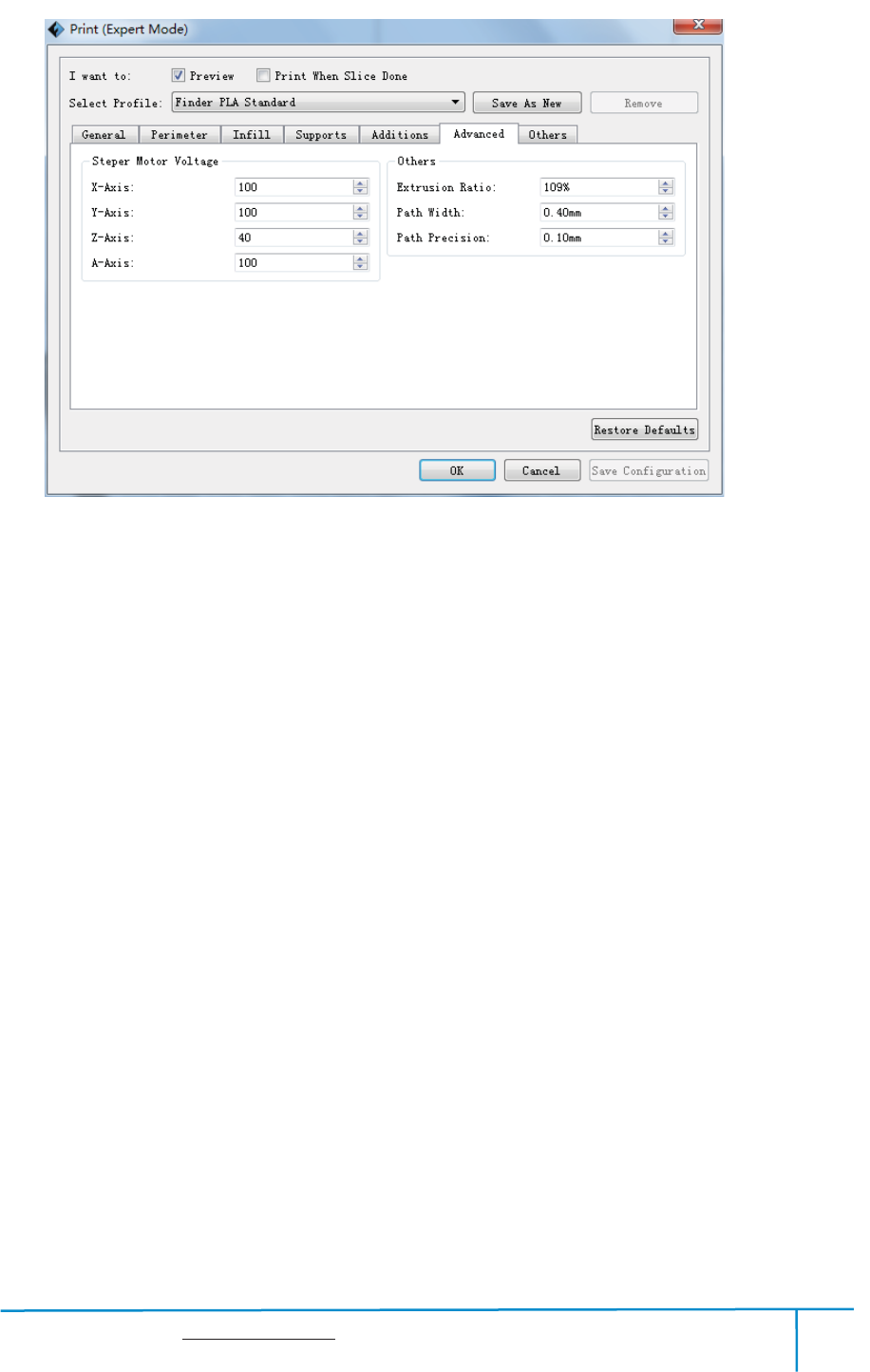
Advanced
1˅Stepper Motor Voltage(Usually keep default)
a. X-Axis: Voltage parameter of X-axis stepper motor. The bigger the value is, the
more heater will produce.
b. Y-Axis: Voltage parameter of Y-axis stepper motor. The bigger the value is, the
more heater will produce.
c. Z-Axis: Voltage parameter of Z-axis stepper motor. The bigger the value is, the
more heater will produce.
d. A-Axis: Voltage parameter of right-extruder stepper motor. The bigger the value is,
the more heater will produce.
e. B-Axis: Voltage parameter of left-extruder stepper motor. The bigger the value is,
the more heater will produce.
2˅Others
a.Extrusion Ratio: The filament amount extruded by the extruder. Default: 109%
Max:125% (Usually the default ratio is suggested)
8-6
Finder User Guide | www.flashforge.com 0086-0579-82273989
71
b. Path Width: The width of the path, the default value is 0.4mm. Keeping default is
suggested.
c. Path Resolution: The default value is 0.1mm. The bigger the value is, the lower the
extrusion resolution is. On the contrary, the extrusion resolution is much higher.
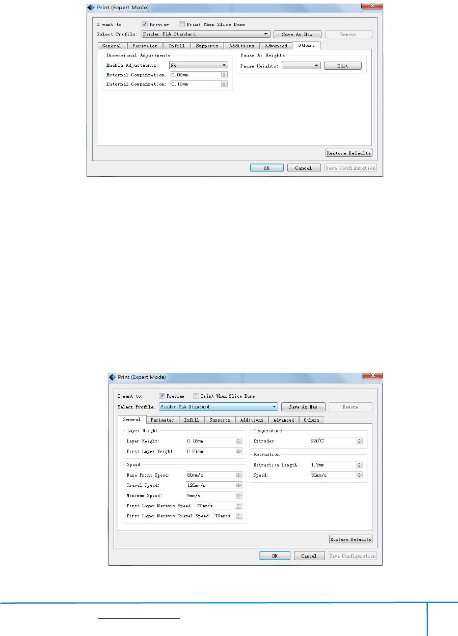
Others
DimensionalAdjustment
a.EnableAdjustments:Enablesoftwaretomakecompensationforerrors.
b. External Compensation: Enable software to make compensation for the outer
diametererror.
c. Internal Compensation: Enable software to make compensation for the inner
diametererror.
8-8
8-7

Finder User Guide | www.flashforge.com 0086-0579-82273989
72
Save as new
Allows users to save the model as a new file after parameter modification.
How to do?
After getting all the required parameters modified, click [Save as new], then a
dialogue box will pop up. Users need to enter the file name into the box, then click
[OK]. Click the drop-down menu of [Select Profile], the new added scheme can be
found in the list.
Remove
Allows the users to delete the added scheme(s). Select one of the added schemes, click
[Remove] and a dialogue box will pop up for confirmation. Click [Yes] to remove it or
click [No] to cancel the current operation.
Restore Default: Allows users to restore to the default settings.
Save Configuration: Allows users to save the present configuration.
8.1 Skills on Supports
(Reference Video
˖
Skills on Supports)
Support structures enable the printing of models with steep overhangs and cantilevered
sections. The Finder 3D printer utilizes Fused Filament Fabrication (FFF) technology,
which works on the additive manufacturing principle of heating and laying down
material layer by layer to create an object. Many sophisticated 3D print designs require
materials to be deposited on a layer where there was not a previous layer, or the
designs have steep angles which might cause undesired drooping during the print. In
these cases, support structures are needed to ensure objects integrity and print quality.
Principle of 45 Degreesķ
Generally speaking, if the 3D model has an overhang of more than 45 degrees, you
will need supports. This angle is determined by the material, layer height, extrusion

Finder User Guide | www.flashforge.com 0086-0579-82273989
73
width, and temperature. It is critical to adjust the support structures accordingly to
ensure the best print result, especially for large 3D prints.The principle is raised by a
stage designer and widely accepted among the 3D printing industry.
Principle of Pĸroportionality
As for the application of supports, users are suggested to comply with the principle of
proportionality. Even though the supports algorithm has been developing, adding
supports intelligently cannot be realized at present. Therefore, users are always
oriented in adding the supports. As we all know, excessive supports will definitely
result in difficulty in supports removal, while limited supports cannot ensure the
stability of the model. Since FashPrint has the function of manual modification, users
can add proper supports to their models according to the daily experience and the
academic principles.
Support Types
Linear Support Structure˖Suitable for models with large-area overhang(s).
Features˖Full coverage of supports improves the model stability. But the supports on
the surface are difficult to be removed and will definitely reduce the print quality.
Treelike Support Structure˖Suitable for models with small area overhang(s).(You
are suggested printing a raft)
Features˖Treelike support structure is proprietary to Flashforge Corporation. And this
structure can save support material and can be easily removed. However, compared
with the linear support structure, it’s of less stability. So you are suggested to manually
add more supports after auto-generating treelike supports.
Auto-supports
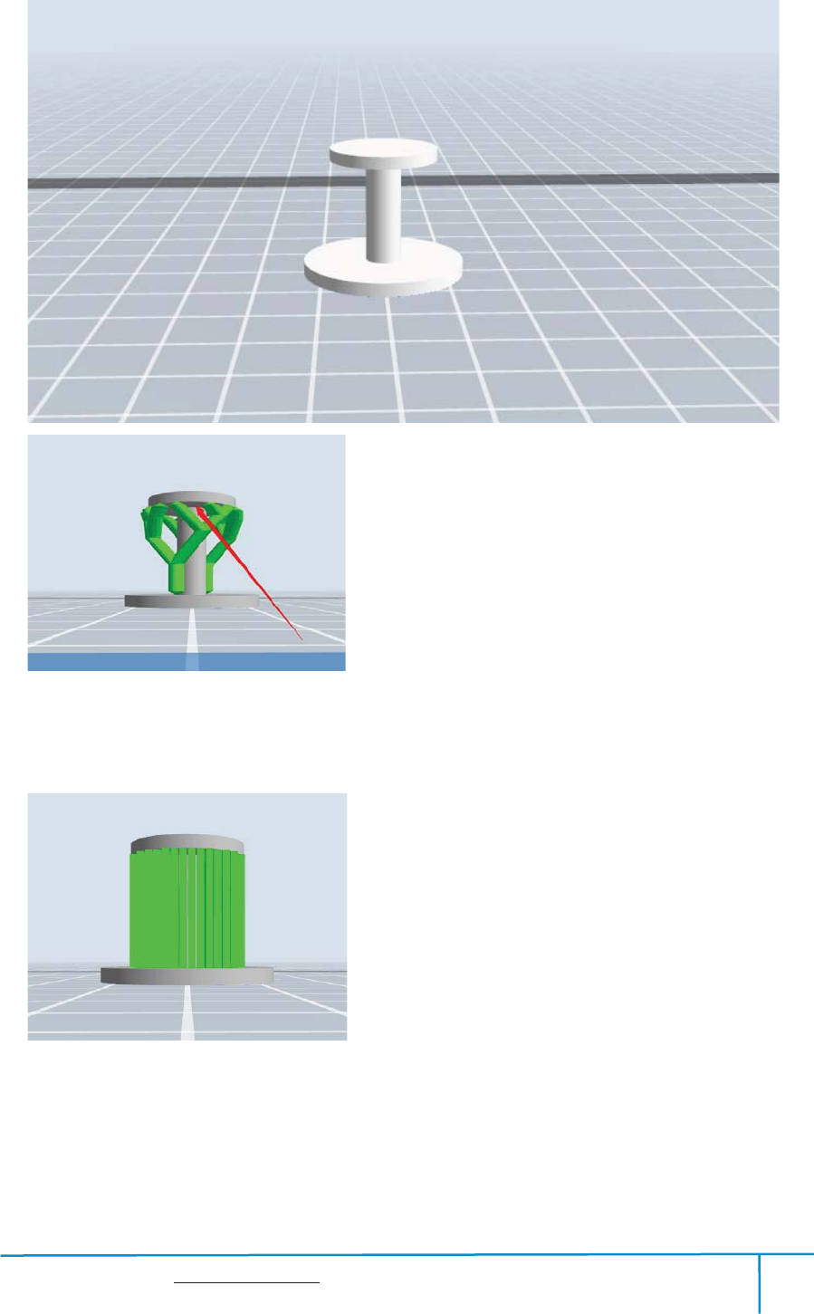
Eg͵1) Model with Large-area Overhang
Finder User Guide | www.flashforge.com 0086-0579-82273989
74
Right:Treelike support structure
Wrong:Linear support structure
Finder User Guide | www.flashforge.com 0086-0579-82273989
75
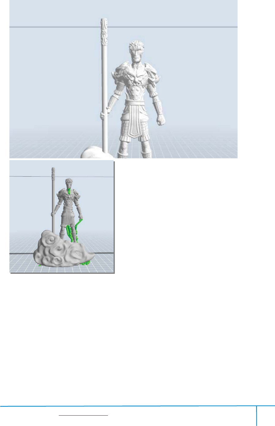
2) Model with Small-area Overhang
Right:Treelike support structure
Finder User Guide | www.flashforge.com 0086-0579-82273989
76
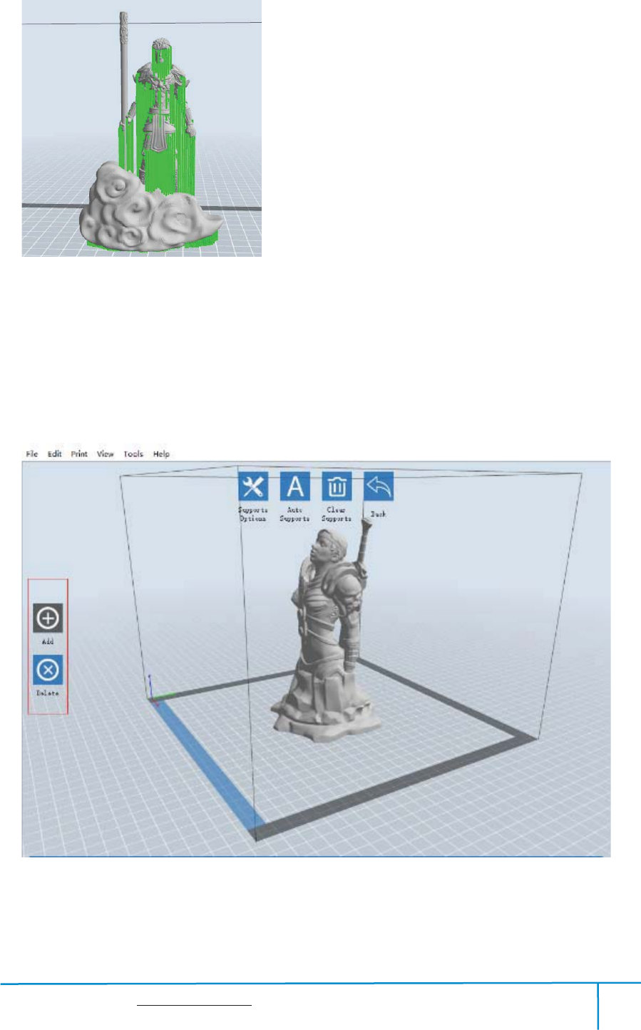
Wrong:Linear support structure
Manual Modification
8-9
For the experienced 3D printer users, the [Add] and [Delete] buttons are suggested
using for manually adding or deleting supports.
Finder User Guide | www.flashforge.com 0086-0579-82273989
77
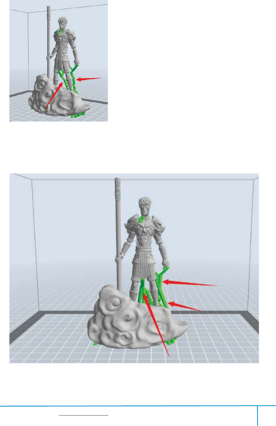
1ͤManual Add
8-10
You can add the support structure manually to according to the actual shape of the
model.
Left click [Add] on the left, and then click on the position when support structure is
Finder User Guide | www.flashforge.com 0086-0579-82273989
78
needed. Press down the left mouse button and drag to generate the support.
2
˅
Manual Delete
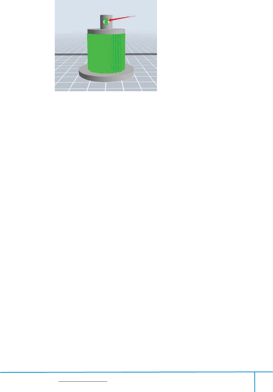
8-11
Like the picture above, a hole inside the model doesn’t need any supports.
Left click the [Delete] button and then left click the supports needed deleting. And the
support will be deleted.
8.2 Control over Printing Quality
Enhance the build plate adhesivenessķ
Leveling the build plate
Keeping the build plate smooth and tidy
Using the build tape or glue
Adjusting the printing speedĸ
Low (Fast) (Print Speed 80mm/s Travel Speed 100mm/s)
Standard (Print Speed 60mm/s Travel Speed 80mm/s)
High (Slow) (Print Speed 50mm/s Travel Speed 70mm/s)
Hyper (Print Speed 50mm/s Travel Speed 70mm/s)
8.3 Skills of Model Placement
Finder User Guide | www.flashforge.com 0086-0579-82273989
79
Not all the models are in the right positions after being loaded. Therefore, you need to
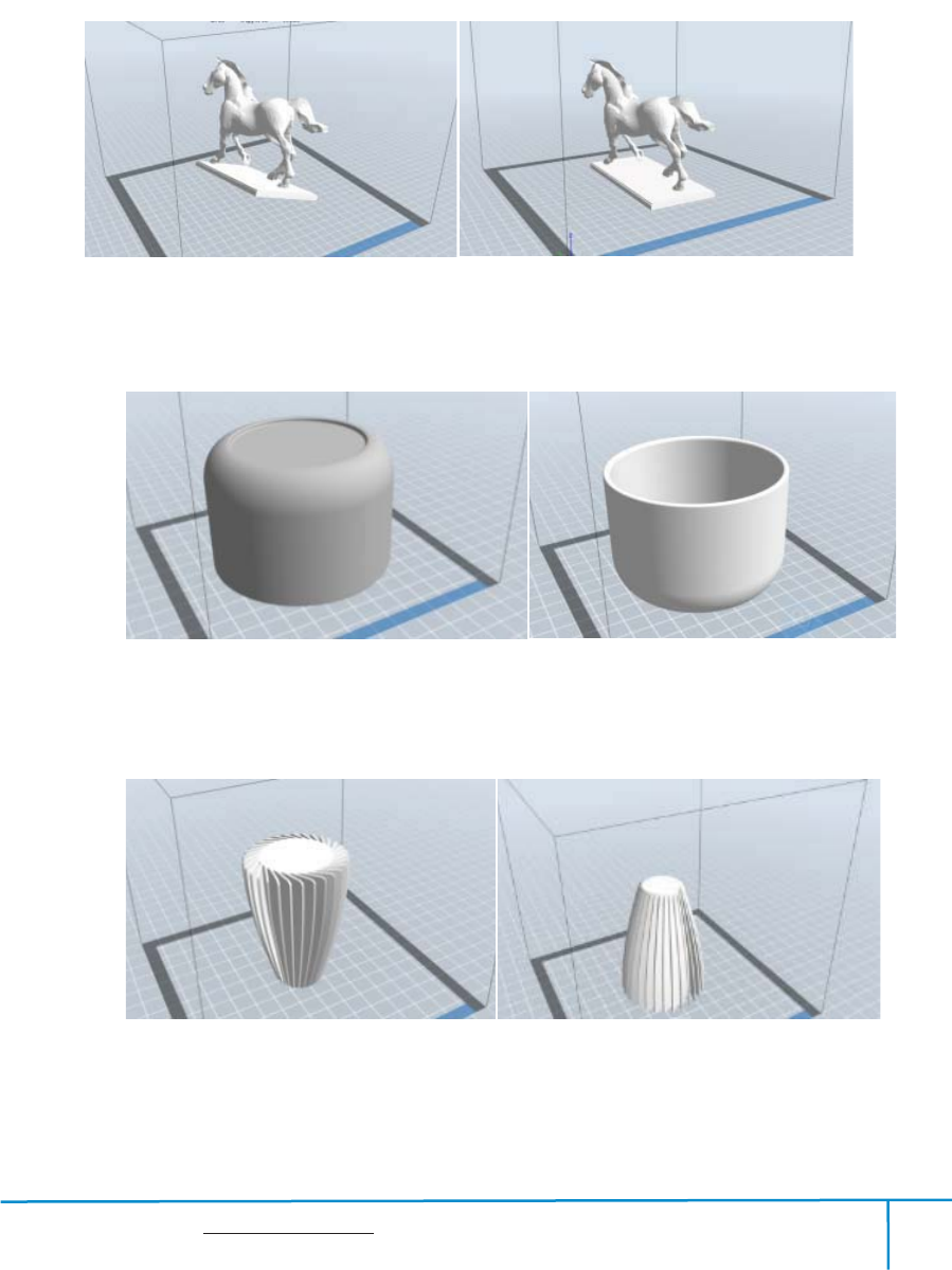
place it in an appropriate position for better print quality. Such as the models below,
you need to put one of the surfaces onto the platform.(Please refer to 5.1.12- Surface Ľ
to Platform)
ķ
ĸ
Ĺ
ImproperProper
8-12
Improper Proper
8-14
Improper Proper
8-13
Finder User Guide | www.flashforge.com 0086-0579-82273989
80
Further Reading
˖
Cut Function
Left-click on the model to select it and double-click on the Cut icon to set the cut
plane. The direction and position are available for setting.
E.g
˖
As for a big model or an irregular model, you need to cut it into several parts so as to
reduce the printing limitation and to better the print quality. Look at the model below:
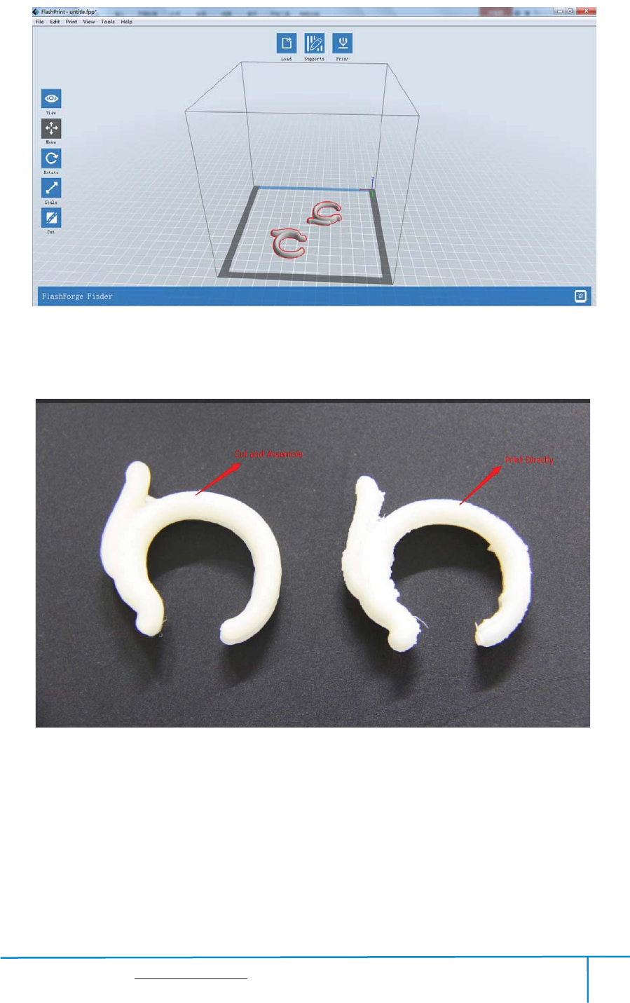
Picture 8-15 is the preview of the model’s original placement and Picture 8-16 is the
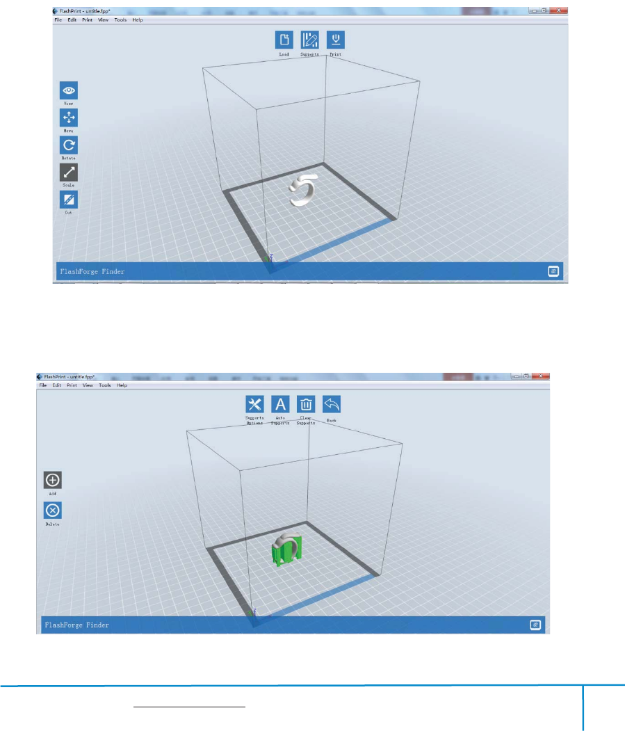
preview of the model with support structure.
8-15
(8-16) Model with support structure
8-16
Finder User Guide | www.flashforge.com 0086-0579-82273989
81
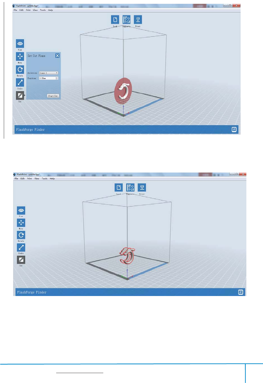
(8-17) Looking at the Picture 8-16, we will definitely find that the complex supports
will influence the smoothness of the model. By analyzing the model’s feature, cutting
from the Y plane will be suitable.
8-17
(8-18) The model preview after cutting.
8-18
(8-19) Click [Edit]--[Surface to Platform] to put the flat surfaces onto the platform.
Finder User Guide | www.flashforge.com 0086-0579-82273989
82
710
Comparison
819

Finder User Guide | www.flashforge.com 0086-0579-82273989
83
Chapter 9: Supports and Service
Flashforge team is on standby and ready to help you withany challenges you may have
with your Finder. If the issues or questionsare notcovered in this User Guide, you can
seek for solutions on our official website or contact us via telephone.
There are solutions and instructions to common issues that can be found in
ourknowledge base. Have a look first as most basic questions are answered there.
http://www.flashforge.com
The FlashForge support team can be reached by e-mail or phone between theworking
hours of 8:00 a.m. to 5:00 p.m. PST Monday through Saturday. In case you contact
usduring after-hours, your inquiry will be answered the following business day.
Note: Because of changing different filament the extruder maybe blockaded. It’s
not owing to quality issue, and outside the scope of 400 hours life. If users
encounter this problem, please contact our after-sale department and finish clean
work according to their instruction.
Tel
˖
86-0579-89316036
QQ
˖
2850862986 28508630002853382161
ADD͵No. 518, Xianyuan Road, Wucheng, Jinhua, Zhejiang
n
Any Changes or modifications not expressly approved by the party responsible for
compliance could void the user’s authority to operate the equipment.
This device complies with part 15 of the FCC Rules. Operation is subject to the following
two conditions: (1) This device may not cause harmful interference, and (2) this device must
accept any interference received, including interference that may cause undesired operation.
*When contacting support, please have your serial number ready. The
serial number is a bar code on the back of your Finder.”

Finder User Guide | www.flashforge.com 0086-0579-82273989
84
Note: This equipment has been tested and found to comply with the limits for a Class B digital
device, pursuant to part 15 of the FCC Rules. These limits are designed to provide reasonable
protection against harmful interference in a residential installation. This equipment generates
uses and can radiate radio frequency energy and, if not installed and used in accordance with
the instructions, may cause harmful interference to radio communications. However, there is no
guarantee that interference will not occur in a particular installation. If this equipment does
cause harmful interference to radio or television reception, which can be determined by turning
the equipment off and on, the user is encouraged to try to correct the interference by one or
more of the following measures:
—Reorient or relocate the receiving antenna.
—Increase the separation between the equipment and receiver.
—Connect the equipment into an outlet on a circuit different from that to which the receiver is
connected.
—Consult the dealer or an experienced radio/TV technician for help.
FCC Radiation Exposure Statement:
This equipment complies with FCC radiation exposure limits set forth for an uncontrolled
environment .This equipment should be installed and operated with minimum distance 20cm
between the radiator& your body.